EP3693944B1 - Method and device for short-term path planning of autonomous driving through information fusion by using v2x communication and image processing - Google Patents
Method and device for short-term path planning of autonomous driving through information fusion by using v2x communication and image processing Download PDFInfo
- Publication number
- EP3693944B1 EP3693944B1 EP20153511.9A EP20153511A EP3693944B1 EP 3693944 B1 EP3693944 B1 EP 3693944B1 EP 20153511 A EP20153511 A EP 20153511A EP 3693944 B1 EP3693944 B1 EP 3693944B1
- Authority
- EP
- European Patent Office
- Prior art keywords
- information
- vehicle
- interfering
- communication
- computing device
- Prior art date
- Legal status (The legal status is an assumption and is not a legal conclusion. Google has not performed a legal analysis and makes no representation as to the accuracy of the status listed.)
- Active
Links
Images


Classifications
-
- B—PERFORMING OPERATIONS; TRANSPORTING
- B60—VEHICLES IN GENERAL
- B60W—CONJOINT CONTROL OF VEHICLE SUB-UNITS OF DIFFERENT TYPE OR DIFFERENT FUNCTION; CONTROL SYSTEMS SPECIALLY ADAPTED FOR HYBRID VEHICLES; ROAD VEHICLE DRIVE CONTROL SYSTEMS FOR PURPOSES NOT RELATED TO THE CONTROL OF A PARTICULAR SUB-UNIT
- B60W30/00—Purposes of road vehicle drive control systems not related to the control of a particular sub-unit, e.g. of systems using conjoint control of vehicle sub-units
- B60W30/08—Active safety systems predicting or avoiding probable or impending collision or attempting to minimise its consequences
- B60W30/095—Predicting travel path or likelihood of collision
- B60W30/0956—Predicting travel path or likelihood of collision the prediction being responsive to traffic or environmental parameters
-
- G—PHYSICS
- G05—CONTROLLING; REGULATING
- G05D—SYSTEMS FOR CONTROLLING OR REGULATING NON-ELECTRIC VARIABLES
- G05D1/00—Control of position, course, altitude or attitude of land, water, air or space vehicles, e.g. using automatic pilots
- G05D1/02—Control of position or course in two dimensions
- G05D1/021—Control of position or course in two dimensions specially adapted to land vehicles
- G05D1/0212—Control of position or course in two dimensions specially adapted to land vehicles with means for defining a desired trajectory
- G05D1/0221—Control of position or course in two dimensions specially adapted to land vehicles with means for defining a desired trajectory involving a learning process
-
- B—PERFORMING OPERATIONS; TRANSPORTING
- B60—VEHICLES IN GENERAL
- B60R—VEHICLES, VEHICLE FITTINGS, OR VEHICLE PARTS, NOT OTHERWISE PROVIDED FOR
- B60R11/00—Arrangements for holding or mounting articles, not otherwise provided for
- B60R11/04—Mounting of cameras operative during drive; Arrangement of controls thereof relative to the vehicle
-
- B—PERFORMING OPERATIONS; TRANSPORTING
- B60—VEHICLES IN GENERAL
- B60W—CONJOINT CONTROL OF VEHICLE SUB-UNITS OF DIFFERENT TYPE OR DIFFERENT FUNCTION; CONTROL SYSTEMS SPECIALLY ADAPTED FOR HYBRID VEHICLES; ROAD VEHICLE DRIVE CONTROL SYSTEMS FOR PURPOSES NOT RELATED TO THE CONTROL OF A PARTICULAR SUB-UNIT
- B60W30/00—Purposes of road vehicle drive control systems not related to the control of a particular sub-unit, e.g. of systems using conjoint control of vehicle sub-units
- B60W30/08—Active safety systems predicting or avoiding probable or impending collision or attempting to minimise its consequences
- B60W30/095—Predicting travel path or likelihood of collision
-
- B—PERFORMING OPERATIONS; TRANSPORTING
- B60—VEHICLES IN GENERAL
- B60W—CONJOINT CONTROL OF VEHICLE SUB-UNITS OF DIFFERENT TYPE OR DIFFERENT FUNCTION; CONTROL SYSTEMS SPECIALLY ADAPTED FOR HYBRID VEHICLES; ROAD VEHICLE DRIVE CONTROL SYSTEMS FOR PURPOSES NOT RELATED TO THE CONTROL OF A PARTICULAR SUB-UNIT
- B60W30/00—Purposes of road vehicle drive control systems not related to the control of a particular sub-unit, e.g. of systems using conjoint control of vehicle sub-units
- B60W30/10—Path keeping
-
- B—PERFORMING OPERATIONS; TRANSPORTING
- B60—VEHICLES IN GENERAL
- B60W—CONJOINT CONTROL OF VEHICLE SUB-UNITS OF DIFFERENT TYPE OR DIFFERENT FUNCTION; CONTROL SYSTEMS SPECIALLY ADAPTED FOR HYBRID VEHICLES; ROAD VEHICLE DRIVE CONTROL SYSTEMS FOR PURPOSES NOT RELATED TO THE CONTROL OF A PARTICULAR SUB-UNIT
- B60W30/00—Purposes of road vehicle drive control systems not related to the control of a particular sub-unit, e.g. of systems using conjoint control of vehicle sub-units
- B60W30/18—Propelling the vehicle
- B60W30/18009—Propelling the vehicle related to particular drive situations
- B60W30/18163—Lane change; Overtaking manoeuvres
-
- B—PERFORMING OPERATIONS; TRANSPORTING
- B60—VEHICLES IN GENERAL
- B60W—CONJOINT CONTROL OF VEHICLE SUB-UNITS OF DIFFERENT TYPE OR DIFFERENT FUNCTION; CONTROL SYSTEMS SPECIALLY ADAPTED FOR HYBRID VEHICLES; ROAD VEHICLE DRIVE CONTROL SYSTEMS FOR PURPOSES NOT RELATED TO THE CONTROL OF A PARTICULAR SUB-UNIT
- B60W40/00—Estimation or calculation of non-directly measurable driving parameters for road vehicle drive control systems not related to the control of a particular sub unit, e.g. by using mathematical models
- B60W40/02—Estimation or calculation of non-directly measurable driving parameters for road vehicle drive control systems not related to the control of a particular sub unit, e.g. by using mathematical models related to ambient conditions
-
- B—PERFORMING OPERATIONS; TRANSPORTING
- B60—VEHICLES IN GENERAL
- B60W—CONJOINT CONTROL OF VEHICLE SUB-UNITS OF DIFFERENT TYPE OR DIFFERENT FUNCTION; CONTROL SYSTEMS SPECIALLY ADAPTED FOR HYBRID VEHICLES; ROAD VEHICLE DRIVE CONTROL SYSTEMS FOR PURPOSES NOT RELATED TO THE CONTROL OF A PARTICULAR SUB-UNIT
- B60W40/00—Estimation or calculation of non-directly measurable driving parameters for road vehicle drive control systems not related to the control of a particular sub unit, e.g. by using mathematical models
- B60W40/10—Estimation or calculation of non-directly measurable driving parameters for road vehicle drive control systems not related to the control of a particular sub unit, e.g. by using mathematical models related to vehicle motion
- B60W40/105—Speed
-
- B—PERFORMING OPERATIONS; TRANSPORTING
- B60—VEHICLES IN GENERAL
- B60W—CONJOINT CONTROL OF VEHICLE SUB-UNITS OF DIFFERENT TYPE OR DIFFERENT FUNCTION; CONTROL SYSTEMS SPECIALLY ADAPTED FOR HYBRID VEHICLES; ROAD VEHICLE DRIVE CONTROL SYSTEMS FOR PURPOSES NOT RELATED TO THE CONTROL OF A PARTICULAR SUB-UNIT
- B60W60/00—Drive control systems specially adapted for autonomous road vehicles
- B60W60/001—Planning or execution of driving tasks
- B60W60/0027—Planning or execution of driving tasks using trajectory prediction for other traffic participants
- B60W60/00276—Planning or execution of driving tasks using trajectory prediction for other traffic participants for two or more other traffic participants
-
- G—PHYSICS
- G05—CONTROLLING; REGULATING
- G05D—SYSTEMS FOR CONTROLLING OR REGULATING NON-ELECTRIC VARIABLES
- G05D1/00—Control of position, course, altitude or attitude of land, water, air or space vehicles, e.g. using automatic pilots
- G05D1/02—Control of position or course in two dimensions
- G05D1/021—Control of position or course in two dimensions specially adapted to land vehicles
- G05D1/0231—Control of position or course in two dimensions specially adapted to land vehicles using optical position detecting means
- G05D1/0246—Control of position or course in two dimensions specially adapted to land vehicles using optical position detecting means using a video camera in combination with image processing means
-
- G—PHYSICS
- G05—CONTROLLING; REGULATING
- G05D—SYSTEMS FOR CONTROLLING OR REGULATING NON-ELECTRIC VARIABLES
- G05D1/00—Control of position, course, altitude or attitude of land, water, air or space vehicles, e.g. using automatic pilots
- G05D1/02—Control of position or course in two dimensions
- G05D1/021—Control of position or course in two dimensions specially adapted to land vehicles
- G05D1/0276—Control of position or course in two dimensions specially adapted to land vehicles using signals provided by a source external to the vehicle
-
- G—PHYSICS
- G05—CONTROLLING; REGULATING
- G05D—SYSTEMS FOR CONTROLLING OR REGULATING NON-ELECTRIC VARIABLES
- G05D1/00—Control of position, course, altitude or attitude of land, water, air or space vehicles, e.g. using automatic pilots
- G05D1/02—Control of position or course in two dimensions
- G05D1/021—Control of position or course in two dimensions specially adapted to land vehicles
- G05D1/0287—Control of position or course in two dimensions specially adapted to land vehicles involving a plurality of land vehicles, e.g. fleet or convoy travelling
-
- G—PHYSICS
- G06—COMPUTING OR CALCULATING; COUNTING
- G06F—ELECTRIC DIGITAL DATA PROCESSING
- G06F18/00—Pattern recognition
- G06F18/20—Analysing
- G06F18/21—Design or setup of recognition systems or techniques; Extraction of features in feature space; Blind source separation
- G06F18/214—Generating training patterns; Bootstrap methods, e.g. bagging or boosting
-
- G—PHYSICS
- G06—COMPUTING OR CALCULATING; COUNTING
- G06F—ELECTRIC DIGITAL DATA PROCESSING
- G06F18/00—Pattern recognition
- G06F18/20—Analysing
- G06F18/25—Fusion techniques
-
- G—PHYSICS
- G06—COMPUTING OR CALCULATING; COUNTING
- G06N—COMPUTING ARRANGEMENTS BASED ON SPECIFIC COMPUTATIONAL MODELS
- G06N3/00—Computing arrangements based on biological models
- G06N3/02—Neural networks
- G06N3/04—Architecture, e.g. interconnection topology
- G06N3/042—Knowledge-based neural networks; Logical representations of neural networks
-
- G—PHYSICS
- G06—COMPUTING OR CALCULATING; COUNTING
- G06N—COMPUTING ARRANGEMENTS BASED ON SPECIFIC COMPUTATIONAL MODELS
- G06N3/00—Computing arrangements based on biological models
- G06N3/02—Neural networks
- G06N3/04—Architecture, e.g. interconnection topology
- G06N3/045—Combinations of networks
-
- G—PHYSICS
- G06—COMPUTING OR CALCULATING; COUNTING
- G06N—COMPUTING ARRANGEMENTS BASED ON SPECIFIC COMPUTATIONAL MODELS
- G06N3/00—Computing arrangements based on biological models
- G06N3/02—Neural networks
- G06N3/04—Architecture, e.g. interconnection topology
- G06N3/0464—Convolutional networks [CNN, ConvNet]
-
- G—PHYSICS
- G06—COMPUTING OR CALCULATING; COUNTING
- G06Q—INFORMATION AND COMMUNICATION TECHNOLOGY [ICT] SPECIALLY ADAPTED FOR ADMINISTRATIVE, COMMERCIAL, FINANCIAL, MANAGERIAL OR SUPERVISORY PURPOSES; SYSTEMS OR METHODS SPECIALLY ADAPTED FOR ADMINISTRATIVE, COMMERCIAL, FINANCIAL, MANAGERIAL OR SUPERVISORY PURPOSES, NOT OTHERWISE PROVIDED FOR
- G06Q10/00—Administration; Management
- G06Q10/04—Forecasting or optimisation specially adapted for administrative or management purposes, e.g. linear programming or "cutting stock problem"
- G06Q10/047—Optimisation of routes or paths, e.g. travelling salesman problem
-
- G—PHYSICS
- G06—COMPUTING OR CALCULATING; COUNTING
- G06T—IMAGE DATA PROCESSING OR GENERATION, IN GENERAL
- G06T7/00—Image analysis
- G06T7/70—Determining position or orientation of objects or cameras
-
- G—PHYSICS
- G06—COMPUTING OR CALCULATING; COUNTING
- G06V—IMAGE OR VIDEO RECOGNITION OR UNDERSTANDING
- G06V10/00—Arrangements for image or video recognition or understanding
- G06V10/20—Image preprocessing
- G06V10/25—Determination of region of interest [ROI] or a volume of interest [VOI]
-
- G—PHYSICS
- G06—COMPUTING OR CALCULATING; COUNTING
- G06V—IMAGE OR VIDEO RECOGNITION OR UNDERSTANDING
- G06V10/00—Arrangements for image or video recognition or understanding
- G06V10/70—Arrangements for image or video recognition or understanding using pattern recognition or machine learning
- G06V10/764—Arrangements for image or video recognition or understanding using pattern recognition or machine learning using classification, e.g. of video objects
-
- G—PHYSICS
- G06—COMPUTING OR CALCULATING; COUNTING
- G06V—IMAGE OR VIDEO RECOGNITION OR UNDERSTANDING
- G06V10/00—Arrangements for image or video recognition or understanding
- G06V10/70—Arrangements for image or video recognition or understanding using pattern recognition or machine learning
- G06V10/82—Arrangements for image or video recognition or understanding using pattern recognition or machine learning using neural networks
-
- G—PHYSICS
- G06—COMPUTING OR CALCULATING; COUNTING
- G06V—IMAGE OR VIDEO RECOGNITION OR UNDERSTANDING
- G06V20/00—Scenes; Scene-specific elements
- G06V20/50—Context or environment of the image
- G06V20/52—Surveillance or monitoring of activities, e.g. for recognising suspicious objects
- G06V20/54—Surveillance or monitoring of activities, e.g. for recognising suspicious objects of traffic, e.g. cars on the road, trains or boats
-
- G—PHYSICS
- G06—COMPUTING OR CALCULATING; COUNTING
- G06V—IMAGE OR VIDEO RECOGNITION OR UNDERSTANDING
- G06V20/00—Scenes; Scene-specific elements
- G06V20/50—Context or environment of the image
- G06V20/56—Context or environment of the image exterior to a vehicle by using sensors mounted on the vehicle
-
- G—PHYSICS
- G06—COMPUTING OR CALCULATING; COUNTING
- G06V—IMAGE OR VIDEO RECOGNITION OR UNDERSTANDING
- G06V20/00—Scenes; Scene-specific elements
- G06V20/50—Context or environment of the image
- G06V20/56—Context or environment of the image exterior to a vehicle by using sensors mounted on the vehicle
- G06V20/58—Recognition of moving objects or obstacles, e.g. vehicles or pedestrians; Recognition of traffic objects, e.g. traffic signs, traffic lights or roads
-
- G—PHYSICS
- G06—COMPUTING OR CALCULATING; COUNTING
- G06V—IMAGE OR VIDEO RECOGNITION OR UNDERSTANDING
- G06V20/00—Scenes; Scene-specific elements
- G06V20/50—Context or environment of the image
- G06V20/56—Context or environment of the image exterior to a vehicle by using sensors mounted on the vehicle
- G06V20/58—Recognition of moving objects or obstacles, e.g. vehicles or pedestrians; Recognition of traffic objects, e.g. traffic signs, traffic lights or roads
- G06V20/584—Recognition of moving objects or obstacles, e.g. vehicles or pedestrians; Recognition of traffic objects, e.g. traffic signs, traffic lights or roads of vehicle lights or traffic lights
-
- G—PHYSICS
- G06—COMPUTING OR CALCULATING; COUNTING
- G06V—IMAGE OR VIDEO RECOGNITION OR UNDERSTANDING
- G06V20/00—Scenes; Scene-specific elements
- G06V20/50—Context or environment of the image
- G06V20/56—Context or environment of the image exterior to a vehicle by using sensors mounted on the vehicle
- G06V20/588—Recognition of the road, e.g. of lane markings; Recognition of the vehicle driving pattern in relation to the road
-
- G—PHYSICS
- G06—COMPUTING OR CALCULATING; COUNTING
- G06V—IMAGE OR VIDEO RECOGNITION OR UNDERSTANDING
- G06V20/00—Scenes; Scene-specific elements
- G06V20/60—Type of objects
- G06V20/62—Text, e.g. of license plates, overlay texts or captions on TV images
- G06V20/625—License plates
-
- G—PHYSICS
- G08—SIGNALLING
- G08G—TRAFFIC CONTROL SYSTEMS
- G08G1/00—Traffic control systems for road vehicles
- G08G1/01—Detecting movement of traffic to be counted or controlled
- G08G1/0104—Measuring and analyzing of parameters relative to traffic conditions
- G08G1/0108—Measuring and analyzing of parameters relative to traffic conditions based on the source of data
- G08G1/0112—Measuring and analyzing of parameters relative to traffic conditions based on the source of data from the vehicle, e.g. floating car data [FCD]
-
- G—PHYSICS
- G08—SIGNALLING
- G08G—TRAFFIC CONTROL SYSTEMS
- G08G1/00—Traffic control systems for road vehicles
- G08G1/01—Detecting movement of traffic to be counted or controlled
- G08G1/0104—Measuring and analyzing of parameters relative to traffic conditions
- G08G1/0108—Measuring and analyzing of parameters relative to traffic conditions based on the source of data
- G08G1/0116—Measuring and analyzing of parameters relative to traffic conditions based on the source of data from roadside infrastructure, e.g. beacons
-
- G—PHYSICS
- G08—SIGNALLING
- G08G—TRAFFIC CONTROL SYSTEMS
- G08G1/00—Traffic control systems for road vehicles
- G08G1/01—Detecting movement of traffic to be counted or controlled
- G08G1/017—Detecting movement of traffic to be counted or controlled identifying vehicles
- G08G1/0175—Detecting movement of traffic to be counted or controlled identifying vehicles by photographing vehicles, e.g. when violating traffic rules
-
- G—PHYSICS
- G08—SIGNALLING
- G08G—TRAFFIC CONTROL SYSTEMS
- G08G1/00—Traffic control systems for road vehicles
- G08G1/01—Detecting movement of traffic to be counted or controlled
- G08G1/052—Detecting movement of traffic to be counted or controlled with provision for determining speed or overspeed
-
- G—PHYSICS
- G08—SIGNALLING
- G08G—TRAFFIC CONTROL SYSTEMS
- G08G1/00—Traffic control systems for road vehicles
- G08G1/16—Anti-collision systems
- G08G1/161—Decentralised systems, e.g. inter-vehicle communication
- G08G1/163—Decentralised systems, e.g. inter-vehicle communication involving continuous checking
-
- G—PHYSICS
- G08—SIGNALLING
- G08G—TRAFFIC CONTROL SYSTEMS
- G08G1/00—Traffic control systems for road vehicles
- G08G1/16—Anti-collision systems
- G08G1/164—Centralised systems, e.g. external to vehicles
-
- G—PHYSICS
- G08—SIGNALLING
- G08G—TRAFFIC CONTROL SYSTEMS
- G08G1/00—Traffic control systems for road vehicles
- G08G1/16—Anti-collision systems
- G08G1/167—Driving aids for lane monitoring, lane changing, e.g. blind spot detection
-
- H—ELECTRICITY
- H04—ELECTRIC COMMUNICATION TECHNIQUE
- H04W—WIRELESS COMMUNICATION NETWORKS
- H04W4/00—Services specially adapted for wireless communication networks; Facilities therefor
- H04W4/30—Services specially adapted for particular environments, situations or purposes
- H04W4/40—Services specially adapted for particular environments, situations or purposes for vehicles, e.g. vehicle-to-pedestrians [V2P]
- H04W4/44—Services specially adapted for particular environments, situations or purposes for vehicles, e.g. vehicle-to-pedestrians [V2P] for communication between vehicles and infrastructures, e.g. vehicle-to-cloud [V2C] or vehicle-to-home [V2H]
-
- B—PERFORMING OPERATIONS; TRANSPORTING
- B60—VEHICLES IN GENERAL
- B60W—CONJOINT CONTROL OF VEHICLE SUB-UNITS OF DIFFERENT TYPE OR DIFFERENT FUNCTION; CONTROL SYSTEMS SPECIALLY ADAPTED FOR HYBRID VEHICLES; ROAD VEHICLE DRIVE CONTROL SYSTEMS FOR PURPOSES NOT RELATED TO THE CONTROL OF A PARTICULAR SUB-UNIT
- B60W50/00—Details of control systems for road vehicle drive control not related to the control of a particular sub-unit, e.g. process diagnostic or vehicle driver interfaces
- B60W2050/0062—Adapting control system settings
- B60W2050/0075—Automatic parameter input, automatic initialising or calibrating means
- B60W2050/0083—Setting, resetting, calibration
- B60W2050/0088—Adaptive recalibration
-
- B—PERFORMING OPERATIONS; TRANSPORTING
- B60—VEHICLES IN GENERAL
- B60W—CONJOINT CONTROL OF VEHICLE SUB-UNITS OF DIFFERENT TYPE OR DIFFERENT FUNCTION; CONTROL SYSTEMS SPECIALLY ADAPTED FOR HYBRID VEHICLES; ROAD VEHICLE DRIVE CONTROL SYSTEMS FOR PURPOSES NOT RELATED TO THE CONTROL OF A PARTICULAR SUB-UNIT
- B60W2420/00—Indexing codes relating to the type of sensors based on the principle of their operation
- B60W2420/40—Photo, light or radio wave sensitive means, e.g. infrared sensors
- B60W2420/403—Image sensing, e.g. optical camera
-
- B—PERFORMING OPERATIONS; TRANSPORTING
- B60—VEHICLES IN GENERAL
- B60W—CONJOINT CONTROL OF VEHICLE SUB-UNITS OF DIFFERENT TYPE OR DIFFERENT FUNCTION; CONTROL SYSTEMS SPECIALLY ADAPTED FOR HYBRID VEHICLES; ROAD VEHICLE DRIVE CONTROL SYSTEMS FOR PURPOSES NOT RELATED TO THE CONTROL OF A PARTICULAR SUB-UNIT
- B60W2520/00—Input parameters relating to overall vehicle dynamics
- B60W2520/10—Longitudinal speed
-
- B—PERFORMING OPERATIONS; TRANSPORTING
- B60—VEHICLES IN GENERAL
- B60W—CONJOINT CONTROL OF VEHICLE SUB-UNITS OF DIFFERENT TYPE OR DIFFERENT FUNCTION; CONTROL SYSTEMS SPECIALLY ADAPTED FOR HYBRID VEHICLES; ROAD VEHICLE DRIVE CONTROL SYSTEMS FOR PURPOSES NOT RELATED TO THE CONTROL OF A PARTICULAR SUB-UNIT
- B60W2554/00—Input parameters relating to objects
- B60W2554/40—Dynamic objects, e.g. animals, windblown objects
- B60W2554/404—Characteristics
- B60W2554/4041—Position
-
- B—PERFORMING OPERATIONS; TRANSPORTING
- B60—VEHICLES IN GENERAL
- B60W—CONJOINT CONTROL OF VEHICLE SUB-UNITS OF DIFFERENT TYPE OR DIFFERENT FUNCTION; CONTROL SYSTEMS SPECIALLY ADAPTED FOR HYBRID VEHICLES; ROAD VEHICLE DRIVE CONTROL SYSTEMS FOR PURPOSES NOT RELATED TO THE CONTROL OF A PARTICULAR SUB-UNIT
- B60W2554/00—Input parameters relating to objects
- B60W2554/40—Dynamic objects, e.g. animals, windblown objects
- B60W2554/404—Characteristics
- B60W2554/4042—Longitudinal speed
-
- B—PERFORMING OPERATIONS; TRANSPORTING
- B60—VEHICLES IN GENERAL
- B60W—CONJOINT CONTROL OF VEHICLE SUB-UNITS OF DIFFERENT TYPE OR DIFFERENT FUNCTION; CONTROL SYSTEMS SPECIALLY ADAPTED FOR HYBRID VEHICLES; ROAD VEHICLE DRIVE CONTROL SYSTEMS FOR PURPOSES NOT RELATED TO THE CONTROL OF A PARTICULAR SUB-UNIT
- B60W2556/00—Input parameters relating to data
- B60W2556/45—External transmission of data to or from the vehicle
-
- B—PERFORMING OPERATIONS; TRANSPORTING
- B60—VEHICLES IN GENERAL
- B60W—CONJOINT CONTROL OF VEHICLE SUB-UNITS OF DIFFERENT TYPE OR DIFFERENT FUNCTION; CONTROL SYSTEMS SPECIALLY ADAPTED FOR HYBRID VEHICLES; ROAD VEHICLE DRIVE CONTROL SYSTEMS FOR PURPOSES NOT RELATED TO THE CONTROL OF A PARTICULAR SUB-UNIT
- B60W2556/00—Input parameters relating to data
- B60W2556/45—External transmission of data to or from the vehicle
- B60W2556/65—Data transmitted between vehicles
-
- B—PERFORMING OPERATIONS; TRANSPORTING
- B60—VEHICLES IN GENERAL
- B60Y—INDEXING SCHEME RELATING TO ASPECTS CROSS-CUTTING VEHICLE TECHNOLOGY
- B60Y2300/00—Purposes or special features of road vehicle drive control systems
- B60Y2300/08—Predicting or avoiding probable or impending collision
-
- B—PERFORMING OPERATIONS; TRANSPORTING
- B60—VEHICLES IN GENERAL
- B60Y—INDEXING SCHEME RELATING TO ASPECTS CROSS-CUTTING VEHICLE TECHNOLOGY
- B60Y2300/00—Purposes or special features of road vehicle drive control systems
- B60Y2300/10—Path keeping
-
- G—PHYSICS
- G06—COMPUTING OR CALCULATING; COUNTING
- G06N—COMPUTING ARRANGEMENTS BASED ON SPECIFIC COMPUTATIONAL MODELS
- G06N3/00—Computing arrangements based on biological models
- G06N3/02—Neural networks
- G06N3/08—Learning methods
-
- G—PHYSICS
- G06—COMPUTING OR CALCULATING; COUNTING
- G06T—IMAGE DATA PROCESSING OR GENERATION, IN GENERAL
- G06T2207/00—Indexing scheme for image analysis or image enhancement
- G06T2207/20—Special algorithmic details
- G06T2207/20084—Artificial neural networks [ANN]
-
- G—PHYSICS
- G06—COMPUTING OR CALCULATING; COUNTING
- G06T—IMAGE DATA PROCESSING OR GENERATION, IN GENERAL
- G06T2207/00—Indexing scheme for image analysis or image enhancement
- G06T2207/30—Subject of image; Context of image processing
- G06T2207/30248—Vehicle exterior or interior
- G06T2207/30252—Vehicle exterior; Vicinity of vehicle
- G06T2207/30256—Lane; Road marking
-
- G—PHYSICS
- G06—COMPUTING OR CALCULATING; COUNTING
- G06V—IMAGE OR VIDEO RECOGNITION OR UNDERSTANDING
- G06V2201/00—Indexing scheme relating to image or video recognition or understanding
- G06V2201/08—Detecting or categorising vehicles
-
- G—PHYSICS
- G06—COMPUTING OR CALCULATING; COUNTING
- G06V—IMAGE OR VIDEO RECOGNITION OR UNDERSTANDING
- G06V2201/00—Indexing scheme relating to image or video recognition or understanding
- G06V2201/09—Recognition of logos
Definitions
- the present disclosure relates to a method and a device for use with an autonomous vehicle; and more particularly, to the method and the device for a short-term path planning of an autonomous driving through a fusion of information, under a road circumstance where both vehicles capable of the V2X communication and vehicles incapable of the V2X communication exist.
- US 2010/042282 A1 discloses a system for generating a travel control plan for an autonomous host vehicle, in a traffic environment in which communicative and non-communicative vehicles coexist as peripheral vehicles to the host vehicle, and wherein generating the travel control plan is based on inferring the behaviour of a peripheral vehicle.
- V2X technology When a vehicle is driven using information generated by other vehicles, driving of the vehicle as well as other vehicles can be secured.
- Any images referred to in the present disclosure may include images related to any roads paved or unpaved, in which case the objects on the roads or near the roads may include vehicles, persons, animals, plants, buildings, flying objects like planes or drones, or any other obstacles which may appear in a road-related scene, but the scope of the present disclosure is not limited thereto.
- said any images referred to in the present disclosure may include images not related to any roads, such as images related to alleyway, land lots, sea, lakes, rivers, mountains, forests, deserts, sky, or any indoor space
- the objects in said any images may include vehicles, persons, animals, plants, buildings, flying objects like planes or drones, ships, amphibious planes or ships, or any other obstacles which may appear in a scene related to alleyway, land lots, sea, lakes, rivers, mountains, forests, deserts, sky, or any indoor space, but the scope of the present disclosure is not limited thereto.
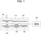
- Fig. 1 is a drawing schematically illustrating a configuration of a computing device performing a method for planning an autonomous driving by using a V2X communication and an image processing under a road circumstance where both vehicles capable of the V2X communication and vehicles incapable of the V2X communication exist in accordance with one example embodiment of the present disclosure.
- the computing device 100 may include at least one V2X communication module 130, at least one image processing module 140, and at least one planning module 150, which are components to be described later. Inputting/outputting processes and operation processes of the V2X communication module 130, the image processing module 140, and the planning module 150 may be performed by at least one communication part 110 and at least one processor 120, respectively. However, detailed communication schematics between the communication part 110 and the processor 120 are omitted in Fig. 1 .
- a memory 115 may have stored various instructions to be described later, and the processor 120 may execute the instructions stored in the memory 115 and may perform processes of the present disclosure by executing the instructions to be disclosed later.
- Such description of the computing device 100 does not exclude an integrated device including any combination of a processor, a memory, a medium, or any other computing components.
- Such computing device 100 may be included in a subject autonomous vehicle, or included in a control server configured to control the subject autonomous vehicle through a remote wireless communication.
- the computing device 100 may interwork with a center server 200 through a communication. That is, to be explained later, the planning method of the present disclosure includes a method for acquiring information on at least one interfering vehicle around the subject autonomous vehicle, even when the interfering vehicle is incapable of the V2X communication, by interworking with the center server 200.
- the computing device 100 may instruct the planning module 150 to interwork with at least one of the V2X communication module 130 and the image processing module 140, to thereby acquire recognition information on at least part of surrounding vehicles.
- the surrounding vehicles may include at least part of a first group including one or more first vehicles capable of the V2X communication and located closer than a threshold distance from the subject autonomous vehicle, and a second group including one or more second vehicles incapable of the V2X communication and also located closer than the threshold distance from the subject autonomous vehicle.
- the computing device may instruct the planning module 150 to select said interfering vehicle, among the surrounding vehicles, by referring to the recognition information and current optimized route information of the subject autonomous vehicle.
- the interfering vehicle may be one of the surrounding vehicles whose probability of obstructing the subject autonomous vehicle is larger than a threshold probability.
- the computing device 100 may instruct the planning module 150 to generate a potential interference prediction model on the interfering vehicle by interworking with at least one of the V2X communication module 130 and the image processing module 140. After that, the computing device 100 may instruct the planning module 150 to modify the current optimized route information in order to evade a potential interfering action of the interfering vehicle, which is estimated by using the potential interference prediction model, to thereby generate updated optimized route information of the subject autonomous vehicle. Such updated optimized route information can be used for planning the autonomous driving.
- the computing device 100 may instruct the planning module 150 to interwork with V2X communication module 130 or the image processing module 140.
- the planning module 150 interworks with the image processing module 140 will be explained below.
- the computing device 100 may instruct a 1-st neural network included in the image processing module 140 to acquire at least one circumstance image, corresponding to at least one direction from the subject autonomous vehicle, through at least one camera installed in the subject autonomous vehicle. After such circumstance image has been acquired, the computing device 100 may instruct the 1-st neural network to apply one or more 1-st neural network operations to the circumstance image, to thereby generate the recognition information.
- the 1-st neural network may include at least one 1-st convolutional layer, at least one 1-st pooling layer, and at least one 1-st FC layer, and may interwork with a 1-st RPN.
- the 1-st neural network operations may be operations, performed by the 1-st convolutional layer, the 1-st pooling layer and the 1-st FC layer, applied to the circumstance image inputted to the 1-st neural network.
- the recognition information may include at least part of (i) vehicle identifier information, (ii) vehicle exterior information, and (iii) vehicle relative location information from the subject autonomous vehicle.
- the vehicle identifier information may include information on one or more registration numbers of the surrounding vehicles, acquired by referring to partial images of license plates of the surrounding vehicles, included in the circumstance image.
- the vehicle exterior information include information on one or more colors, one or more shapes and one or more classes of the surrounding vehicles.
- the vehicle relative location information may include information on one or more relative coordinates of the surrounding vehicles, including one or more longitudinal distances and one or more lateral distances as their components, in relation to the subject autonomous vehicle.
- the recognition information can be acquired through the image processing module 140.
- the computing device 100 may instruct the V2X communication module to communicate with specific surrounding vehicles of the first group, and acquire recognition information on the specific surrounding vehicles.
- the recognition information may be acquired more accurately, but it can be only usable for the specific surrounding vehicles belonging to the first group.
- the recognition information can be acquired through such two ways, by using the image processing module 140 or the V2X communication module 130. Below, how to select the interfering vehicle among the surrounding vehicles will be presented.
- the computing device 100 may instruct the planning module 150 to select the interfering vehicle by referring to the current optimized route information and the recognition information.
- the current optimized route information may include information on a scheduled route of the subject autonomous vehicle planned beforehand, which may be modified after the interfering vehicle is recognized.
- the computing device 100 may instruct the planning module 150 to generate a scheduled direction vector by using scheduled direction information on a direction to which the subject autonomous vehicle is planned to move in a threshold time.
- the computing device 100 may instruct the planning module 150 to generate one or more relative location vectors by using the vehicle relative location information corresponding to at least part of the surrounding vehicles.
- the computing device 100 may instruct the planning module 150 to generate each of similarity scores between the scheduled direction vector and each of the relative location vectors, and select at least one specific surrounding vehicle, among the surrounding vehicles, as the interfering vehicle, whose corresponding specific similarity score is larger than a threshold similarity score.
- the specific surrounding vehicle located in a direction where the subject autonomous vehicle is scheduled to move, is selected as the interfering vehicle, and the specific surrounding vehicle is selected by comparing the scheduled direction vector and the relative location vectors.
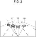
- Fig. 2 will be referred to, in order to explain such process more specifically.
- Fig. 2 is a drawing schematically illustrating how to select an interfering vehicle to perform the method for planning the autonomous driving by using the V2X communication and the image processing under the road circumstance where both the vehicles capable of the V2X communication and the vehicles incapable of the V2X communication exist in accordance with one example embodiment of the present disclosure.
- a first relative location vector 151, a second relative location vector 152, a third relative location vector 153 and a fourth relative location vector 154 may be seen.
- the specific surrounding vehicle corresponding to the third relative location vector may be selected as the interfering vehicle.
- the computing device 100 may instruct the first neural network to generate information on locations, of bounding boxes including the surrounding vehicles, on the circumstance image and information on a current lane region, corresponding to a current lane of a road including the subject autonomous vehicle, of the circumstance image, along with the recognition information.
- Such first neural network can be established by adding some nodes in its final layer for outputting such pieces of information, and making adjusted GT including ground-truth information on the locations of the bounding boxes and the information on the current lane region to be used for training the first neural network.
- the computing device 100 may instruct the planning module 150 to determine whether each of partial images of the surrounding vehicles, i.e., each of regions of the circumstance image corresponding to each of the bounding boxes, is located in the current lane region or not, to find out whether the surrounding vehicles are running in the current lane or not, and select the specific surrounding vehicle running in the current lane as the interfering vehicle.
- Such example embodiment may be applied in case the subject autonomous vehicle is driving in the straight direction.
- the interfering vehicle can be selected as shown above. Below, how to generate the potential interference prediction model will be presented. For generating the potential interference prediction model, there can be different embodiments, which are distinct in their usage of V2X communication module 130 and the image processing module 140. Such different embodiments will be explained in order, case by case.
- the computing device 100 may instruct the V2X communication module 130 to communicate with the interfering vehicle, to thereby acquire scheduled route information of the interfering vehicle, and then to thereby generate the potential interference prediction model by using the scheduled route information.
- the interfering vehicle may transmit its own current optimized route information as the scheduled route information to the computing device 100.
- the computing device 100 may instruct the planning module 150 to generate the potential interference prediction model by referring to estimated velocity range information included in the scheduled route information.
- the interfering vehicle may transmit its current velocity information and its acceleration capability information to the computing device 100, and the computing device 100 may instruct the planning module 150 to generate the potential interference prediction model by using the current velocity information and the acceleration capability information. How the current velocity information and the acceleration capability information are used to generate the potential interference prediction model will be presented later.
- a second example embodiment corresponding to a case of the interfering vehicle belonging to the second group, may include three subordinate example embodiments, i.e., a (2-1)-st example embodiment corresponding to both of the V2X communication module 130 and the image processing module 140, a (2-2)-nd example embodiment corresponding to the image processing module 140, and a (2-3)-rd example embodiment corresponding to the V2X communication module 130.
- a (2-1)-st example embodiment corresponding to both of the V2X communication module 130 and the image processing module 140
- a (2-2)-nd example embodiment corresponding to the image processing module 140
- a (2-3)-rd example embodiment corresponding to the V2X communication module 130.
- the computing device 100 may instruct the image processing module 140 to acquire at least one modeling image including the interfering vehicle through the camera installed in the subject autonomous vehicle.
- the modeling image may be same as the circumstance image, or may be a newly acquired image including the interfering vehicle, photographed later than the circumstance image.
- the computing device 100 may instruct a 2-nd neural network included in the image processing module 140 to apply one or more 2-nd neural network operations to the modeling image, to thereby generate the acceleration capability information and transmit it to the planning module 150.
- Fig. 3 will be referred to.
- Fig. 3 is a drawing schematically illustrating a 2-nd neural network used for performing the method for planning the autonomous driving by using the V2X communication and the image processing under the road circumstance where both the vehicles capable of the V2X communication and the vehicles incapable of the V2X communication exist in accordance with one example embodiment of the present disclosure.
- the 2-nd neural network 142 may include at least one (2-1)-st neural network 142-1 and at least one (2-2)-nd neural network 142-2.
- the (2-1)-st neural network 142-1 may include at least one (2-1)-st convolutional layer, at least one (2-1)-st pooling layer and at least one (2-1)-st FC layer, and may be assisted by a second RPN(not shown).
- the (2-2)-nd neural network 142-2 may include a concatenating layer and a (2-2)-nd FC layer.
- Such (2-1)-st neural network 142-1 and the (2-2)-nd neural network 142-2 may be trained by using at least one 2-nd training image and its corresponding at least one 2-nd GT before performing the planning method of the present disclosure.
- the 2-nd neural network operations may be applied to the modeling image so that operations of the (2-1)-st neural network 142-1 and the (2-2)-nd neural network 142-2 are applied to the modeling image in order.
- the modeling image is inputted to the (2-1)-st neural network 142-1, operations of the (2-1)-st convolutional layer, the (2-1)-st pooling layer and the (2-1)-st FC layer are applied to the modeling image in order, to thereby generate (i) relative velocity information of the interfering vehicle in relation to the subject autonomous vehicle, (ii) category information corresponding to a class of the interfering vehicle, and (iii) acceleration variable information corresponding to at least part of a mass and a volume of the interfering vehicle.
- the relative velocity information, the category information, the acceleration variable information, and further current section average velocity information acquired by V2X communication module 130 from the center server 200, to be explained later, are inputted to the (2-2)-nd neural network 142-2, a concatenated vector including the relative velocity information, the category information, the acceleration variable information, and the current section average velocity information as its components can be generated by the concatenating layer, and the acceleration capability information can be generated by applying operations of the (2-2)-nd FC layer to the concatenated vector.
- the current velocity information is further needed.
- it may be acquired by interworking with the V2X communication module.
- the computing device 100 may instruct the V2X communication module 130 to acquire velocity ratio information and the current section average velocity information, generated by the center server 200.
- the velocity ratio information may have been generated by comparing each of average velocities for each of past sections of a road, where the surrounding vehicles and the subject autonomous vehicle have been driving, with each of velocities of the interfering vehicle in each of the past sections.
- the current section average velocity information may have been generated by calculating an average velocity of vehicles in a current section of a road where the surrounding vehicles and the subject autonomous vehicle are driving currently.
- Such current section average velocity information and the velocity ratio information can be referred to, in order to generate the current velocity information of the interfering vehicle. To explain such process, Fig. 4 will be referred to.
- Fig. 4 is a drawing schematically illustrating how current velocity information of the interfering vehicle is generated by using current section average velocity information, to be used for performing the method for planning the autonomous driving by using the V2X communication and the image processing under the road circumstance where both the vehicles capable of the V2X communication and the vehicles incapable of the V2X communication exist in accordance with one example embodiment of the present disclosure.
- a first velocity(V i1 ) of the interfering vehicle in a first section is 61km/h
- a second velocity(V i2 ) of the interfering vehicle in a second section is 65km/h
- a third velocity(V i3 ) of the interfering vehicle in a third section is 68km/h while a first average velocity(V AVE1 ) of the first section is 95km/h, a second average velocity(V AVE2 ) of the second section is 98km/h
- a third average velocity(V AVE3 ) of the third section is 102km/h.
- Such current section average velocity information and the velocity ratio information may be generated by using each of cameras installed in each of points dividing each of sections.
- the center server 200 may be able to (i) specify each of passing vehicles by using information on their registration numbers and their exteriors, (ii) calculate times spent for covering each of the sections in order to measure each of their velocities, and thus (iii) generate section average velocity information on each of the sections, including the current section average information.
- general velocity ratio information for each of passing vehicles may have been prepared for each of the sections by using each of piece of the section average velocity information.
- the center server 200 acquires information for specifying the interfering vehicle among the passing vehicles, such as the vehicle identifier information and the vehicle exterior information, from the V2X communication module 130, the velocity ratio information for the interfering vehicle, among the general velocity ratio information, may be selected and transmitted to the computing device 100.
- the (2-1)-st example embodiment is as shown above. Below, the (2-2)-nd example embodiment corresponding to the image processing module 140 will be presented.
- the 2-nd neural network 142 may have been configured to have one more node for outputting the current velocity information in the (2-2)-nd FC layer, and may have been trained by using a modified 2-nd GT including GT current velocity information.
- the computing device 100 may instruct the 2-nd neural network included in the image processing module 140 to apply the 2-nd neural network operations to the modeling image, to thereby generate the current velocity information along with the acceleration capability information and then to thereby transmit the current velocity information and the acceleration capability information to the planning module 150. Thereafter, the computing device may instruct the planning module 150 to generate the potential interference prediction model by referring to the current velocity information and the acceleration capability information.
- the V2X communication module 130 may be mainly used to acquire the acceleration capability information and the current velocity information. That is, the computing device 100 may instruct the V2X communication module 130 to communicate with the center server 200 to acquire the acceleration capability information, the velocity ratio information and the current section average velocity information. Thereafter, the computing device 100 may instruct the V2X communication module to transmit the acceleration capability information of the interfering vehicle and the current velocity information of the interfering vehicle calculated by using the velocity ratio information and the current section average velocity information, and may instruct the planning module 150 to generate the potential interference prediction model by referring to the acceleration capability information and the current velocity information.
- the center server 200 may acquire information on categories and loadages of the passing vehicles including the interfering vehicle by using each of the cameras installed in points between each of the sections, to thereby generate the acceleration capability information, and then to thereby transmit it to the computing device 100.
- the computing device 100 may instruct the planning module 150 to generate estimated velocity range information by referring to (i) a TTC value corresponding to a time for the subject autonomous vehicle to evade the potential interfering action, (ii) the acceleration capability information and (iii) the current velocity information, to thereby generate the potential interference prediction model including the estimated velocity range information.
- V range v
- the estimated velocity range information including information on a largest velocity and a smallest velocity of the interfering vehicle in a range of the time corresponding to the TTC value, can be generated by following above formula, and it can be used for generating the potential interference prediction model. Thereafter, the potential interfering action, corresponding to a velocity of the interfering vehicle driving in front of the subject autonomous vehicle, can be predicted by using the potential interference prediction model.
- the computing device 100 may instruct the planning module 150 to generate updated optimized route information by modifying the current optimized route information, in order to evade the potential interfering action.
- the computing device 100 may instruct the planning module 150 to acquire lane average velocity information of at least one surrounding lane located in at least one of a left side and a right side of a current lane including the subject autonomous vehicle.
- Such lane average velocity information may have been acquired by using the cameras located between each of the sections, and transmitted from the center server 200 to the planning module 150, through the V2X communication module 130.
- the computing device 100 may instruct the planning module 150 to modify the current optimized route information in order to add an evading action, to be executed in correspondence with the surrounding lane in order to evade the potential interfering action, by referring to the lane average velocity information, to thereby generate the updated optimized route information.
- the lane average velocity information may have been used for finding a better lane for passing. To explain such usage of the lane average velocity information, Fig. 5 will be referred to.
- Fig. 5 is a drawing schematically illustrating how to modify current optimized route information to be used for performing the method for planning the autonomous driving by using the V2X communication and the image processing under the road circumstance where both the vehicles capable of the V2X communication and the vehicles incapable of the V2X communication exist in accordance with one example embodiment of the present disclosure.
- an average velocity of a lane on the left is larger than that of a lane on the right.
- selecting the lane on the left will be more suitable for passing.
- the lane on the left will be selected, and the evading action by using the lane on the left will be added to the current optimized route information, to thereby generate the updated optimized route information.
- the autonomous driving may be performed properly.
- the present disclosure has an effect of providing a method for planning an autonomous driving by using a V2X communication and an image processing to allow the autonomous driving to be performed more safely.
- the embodiments of the present disclosure as explained above can be implemented in a form of executable program command through a variety of computer means recordable to computer readable media.
- the computer readable media may include solely or in combination, program commands, data files, and data structures.
- the program commands recorded to the media may be components specially designed for the present disclosure or may be usable to a skilled human in a field of computer software.
- Computer readable media include magnetic media such as hard disk, floppy disk, and magnetic tape, optical media such as CD-ROM and DVD, magneto-optical media such as floptical disk and hardware devices such as ROM, RAM, and flash memory specially designed to store and carry out program commands.
- Program commands include not only a machine language code made by a compiler but also a high level language code that can be executed by a computer using an interpreter, etc.
- the hardware device can work as more than a software module to perform the process in accordance with the present disclosure and they can do the same in the opposite case.
Landscapes
- Engineering & Computer Science (AREA)
- Physics & Mathematics (AREA)
- General Physics & Mathematics (AREA)
- Theoretical Computer Science (AREA)
- Multimedia (AREA)
- Automation & Control Theory (AREA)
- Evolutionary Computation (AREA)
- Mechanical Engineering (AREA)
- Artificial Intelligence (AREA)
- Transportation (AREA)
- Computer Vision & Pattern Recognition (AREA)
- Health & Medical Sciences (AREA)
- Computing Systems (AREA)
- General Health & Medical Sciences (AREA)
- Software Systems (AREA)
- Data Mining & Analysis (AREA)
- Medical Informatics (AREA)
- Databases & Information Systems (AREA)
- Mathematical Physics (AREA)
- General Engineering & Computer Science (AREA)
- Life Sciences & Earth Sciences (AREA)
- Radar, Positioning & Navigation (AREA)
- Aviation & Aerospace Engineering (AREA)
- Remote Sensing (AREA)
- Chemical & Material Sciences (AREA)
- Analytical Chemistry (AREA)
- Business, Economics & Management (AREA)
- Human Resources & Organizations (AREA)
- Computational Linguistics (AREA)
- Molecular Biology (AREA)
- Biophysics (AREA)
- Biomedical Technology (AREA)
- Human Computer Interaction (AREA)
- Bioinformatics & Cheminformatics (AREA)
- Economics (AREA)
- Bioinformatics & Computational Biology (AREA)
- Strategic Management (AREA)
- Evolutionary Biology (AREA)
- Computer Networks & Wireless Communication (AREA)
- Signal Processing (AREA)
Description
- The present disclosure relates to a method and a device for use with an autonomous vehicle; and more particularly, to the method and the device for a short-term path planning of an autonomous driving through a fusion of information, under a road circumstance where both vehicles capable of the V2X communication and vehicles incapable of the V2X communication exist.
-
US 2010/042282 A1 discloses a system for generating a travel control plan for an autonomous host vehicle, in a traffic environment in which communicative and non-communicative vehicles coexist as peripheral vehicles to the host vehicle, and wherein generating the travel control plan is based on inferring the behaviour of a peripheral vehicle. - Recently, autonomous driving technologies are attracting great attention. Therefore, it is expected that the autonomous driving technologies will be commercialized in the near future. However, many studies on such autonomous driving technologies have been focused on technologies for safely driving an autonomous vehicle by a computing device installed therein. In other words, technologies for interaction with other vehicles efficiently during the autonomous driving have not been considered much, while the technologies for safely driving itself are mainly considered.
- However, since the amount of information that can be exchanged between vehicles has increased due to the development of communication technologies, it became important to use V2X technology to communicate with other vehicles. When a vehicle is driven using information generated by other vehicles, driving of the vehicle as well as other vehicles can be secured.
- But, there are not many technologies to be used for planning the autonomous driving by actively using such V2X technology.
- It is an object of the present disclosure to solve all the aforementioned problems.
- It is still another object of the present disclosure to provide a method for planning an autonomous driving by using a V2X communication and an image processing to allow the autonomous driving to be performed more safely.
- In accordance with the invention, there is provided a method for planning an autonomous driving as set out in appended claim 1.
- In accordance with the invention, there is provided a computing device for planning an autonomous driving as set out in appended claim 8.
- Embodiments of the method according to invention are as set out in appended claims 2-7. The above and other objects and features of the present disclosure will become apparent from the following description of preferred embodiments given in conjunction with the accompanying drawings.
- The following drawings to be used to explain example embodiments of the present disclosure are only part of example embodiments of the present disclosure and other drawings can be obtained based on the drawings by those skilled in the art of the present disclosure without inventive work.
-
Fig. 1 is a drawing schematically illustrating a configuration of a computing device performing a method for planning an autonomous driving by using a V2X communication and an image processing under a road circumstance where both vehicles capable of the V2X communication and vehicles incapable of the V2X communication exist in accordance with one example embodiment of the present disclosure. -
Fig. 2 is a drawing schematically illustrating how to select an interfering vehicle to perform the method for planning the autonomous driving by using the V2X communication and the image processing under the road circumstance where both the vehicles capable of the V2X communication and the vehicles incapable of the V2X communication exist in accordance with one example embodiment of the present disclosure. -
Fig. 3 is a drawing schematically illustrating a 2-nd neural network used for performing the method for planning the autonomous driving by using the V2X communication and the image processing under the road circumstance where both the vehicles capable of the V2X communication and the vehicles incapable of the V2X communication exist in accordance with one example embodiment of the present disclosure. -
Fig. 4 is a drawing schematically illustrating how current velocity information of the interfering vehicle is generated by using current section average velocity information, to be used for performing the method for planning the autonomous driving by using the V2X communication and the image processing under the road circumstance where both the vehicles capable of the V2X communication and the vehicles incapable of the V2X communication exist in accordance with one example embodiment of the present disclosure. -
Fig. 5 is a drawing schematically illustrating how to modify current optimized route information to be used for performing the method for planning the autonomous driving by using the V2X communication and the image processing under the road circumstance where both the vehicles capable of the V2X communication and the vehicles incapable of the V2X communication exist in accordance with one example embodiment of the present disclosure. - Detailed explanation on the present disclosure to be made below refer to attached drawings and diagrams illustrated as specific embodiment examples under which the present disclosure may be implemented to make clear of purposes, technical solutions, and advantages of the present disclosure. These embodiments are described in sufficient detail to enable those skilled in the art to practice the disclosure.
- Besides, in the detailed description and claims of the present disclosure, a term "include" and its variations are not intended to exclude other technical features, additions, components or steps. Other objects, benefits, and features of the present disclosure will be revealed to one skilled in the art, partially from the specification and partially from the implementation of the present disclosure. The following examples and drawings will be provided as examples but they are not intended to limit the present disclosure.
- Moreover, the present disclosure covers all possible combinations of example embodiments indicated in this specification. It is to be understood that the various embodiments of the present disclosure, although different, are not necessarily mutually exclusive. For example, a particular feature, structure, or characteristic described herein in connection with one embodiment may be implemented within other embodiments without departing from invention as set out in the appended claims. In addition, it is to be understood that the position or arrangement of individual elements within each disclosed embodiment may be modified without departing from the scope of the claims. The following detailed description is, therefore, not to be taken in a limiting sense, and the scope of the present disclosure is defined only by the appended claims, appropriately interpreted. In the drawings, like numerals refer to the same or similar functionality throughout the several views.
- Any images referred to in the present disclosure may include images related to any roads paved or unpaved, in which case the objects on the roads or near the roads may include vehicles, persons, animals, plants, buildings, flying objects like planes or drones, or any other obstacles which may appear in a road-related scene, but the scope of the present disclosure is not limited thereto. As another example, said any images referred to in the present disclosure may include images not related to any roads, such as images related to alleyway, land lots, sea, lakes, rivers, mountains, forests, deserts, sky, or any indoor space, in which case the objects in said any images may include vehicles, persons, animals, plants, buildings, flying objects like planes or drones, ships, amphibious planes or ships, or any other obstacles which may appear in a scene related to alleyway, land lots, sea, lakes, rivers, mountains, forests, deserts, sky, or any indoor space, but the scope of the present disclosure is not limited thereto.
- To allow those skilled in the art to the present disclosure to be carried out easily, the example embodiments of the present disclosure by referring to attached drawings will be explained in detail as shown below.
-
Fig. 1 is a drawing schematically illustrating a configuration of a computing device performing a method for planning an autonomous driving by using a V2X communication and an image processing under a road circumstance where both vehicles capable of the V2X communication and vehicles incapable of the V2X communication exist in accordance with one example embodiment of the present disclosure. - By referring to
Fig. 1 , thecomputing device 100 may include at least oneV2X communication module 130, at least oneimage processing module 140, and at least oneplanning module 150, which are components to be described later. Inputting/outputting processes and operation processes of theV2X communication module 130, theimage processing module 140, and theplanning module 150 may be performed by at least one communication part 110 and at least oneprocessor 120, respectively. However, detailed communication schematics between the communication part 110 and theprocessor 120 are omitted inFig. 1 . Herein, amemory 115 may have stored various instructions to be described later, and theprocessor 120 may execute the instructions stored in thememory 115 and may perform processes of the present disclosure by executing the instructions to be disclosed later. Such description of thecomputing device 100 does not exclude an integrated device including any combination of a processor, a memory, a medium, or any other computing components. -
Such computing device 100 may be included in a subject autonomous vehicle, or included in a control server configured to control the subject autonomous vehicle through a remote wireless communication. - Also, the
computing device 100 may interwork with acenter server 200 through a communication. That is, to be explained later, the planning method of the present disclosure includes a method for acquiring information on at least one interfering vehicle around the subject autonomous vehicle, even when the interfering vehicle is incapable of the V2X communication, by interworking with thecenter server 200. - As seen above, the configuration of the
computing device 100 performing the planning method in accordance with one example embodiment of the present disclosure has been explained. Below, a brief explanation on the planning method of the present disclosure will be provided. - First, the
computing device 100 may instruct theplanning module 150 to interwork with at least one of theV2X communication module 130 and theimage processing module 140, to thereby acquire recognition information on at least part of surrounding vehicles. Herein, the surrounding vehicles may include at least part of a first group including one or more first vehicles capable of the V2X communication and located closer than a threshold distance from the subject autonomous vehicle, and a second group including one or more second vehicles incapable of the V2X communication and also located closer than the threshold distance from the subject autonomous vehicle. - Thereafter, the computing device may instruct the
planning module 150 to select said interfering vehicle, among the surrounding vehicles, by referring to the recognition information and current optimized route information of the subject autonomous vehicle. Herein, the interfering vehicle may be one of the surrounding vehicles whose probability of obstructing the subject autonomous vehicle is larger than a threshold probability. - And, the
computing device 100 may instruct theplanning module 150 to generate a potential interference prediction model on the interfering vehicle by interworking with at least one of theV2X communication module 130 and theimage processing module 140. After that, thecomputing device 100 may instruct theplanning module 150 to modify the current optimized route information in order to evade a potential interfering action of the interfering vehicle, which is estimated by using the potential interference prediction model, to thereby generate updated optimized route information of the subject autonomous vehicle. Such updated optimized route information can be used for planning the autonomous driving. - It has been briefly shown how to perform the planning method of the present disclosure. Below, it will be explained more specifically.
- As a first step for performing the planning method of the present disclosure, in order to acquire recognition information, the
computing device 100 may instruct theplanning module 150 to interwork withV2X communication module 130 or theimage processing module 140. First, how theplanning module 150 interworks with theimage processing module 140 will be explained below. - That is, the
computing device 100 may instruct a 1-st neural network included in theimage processing module 140 to acquire at least one circumstance image, corresponding to at least one direction from the subject autonomous vehicle, through at least one camera installed in the subject autonomous vehicle. After such circumstance image has been acquired, thecomputing device 100 may instruct the 1-st neural network to apply one or more 1-st neural network operations to the circumstance image, to thereby generate the recognition information. As an example, the 1-st neural network may include at least one 1-st convolutional layer, at least one 1-st pooling layer, and at least one 1-st FC layer, and may interwork with a 1-st RPN. Also, it may have been trained by using at least one 1-st training image and its corresponding at least one 1-st GT before performing the planning method of the present disclosure. Herein, the 1-st neural network operations may be operations, performed by the 1-st convolutional layer, the 1-st pooling layer and the 1-st FC layer, applied to the circumstance image inputted to the 1-st neural network. - Herein, the recognition information, generated through such processes of the 1-st neural network, may include at least part of (i) vehicle identifier information, (ii) vehicle exterior information, and (iii) vehicle relative location information from the subject autonomous vehicle. As one example, the vehicle identifier information may include information on one or more registration numbers of the surrounding vehicles, acquired by referring to partial images of license plates of the surrounding vehicles, included in the circumstance image. And, the vehicle exterior information include information on one or more colors, one or more shapes and one or more classes of the surrounding vehicles. Also, the vehicle relative location information may include information on one or more relative coordinates of the surrounding vehicles, including one or more longitudinal distances and one or more lateral distances as their components, in relation to the subject autonomous vehicle. As shown above, the recognition information can be acquired through the
image processing module 140. - Below, how the recognition information is acquired by the
V2X communication module 130 may be explained. Thecomputing device 100 may instruct the V2X communication module to communicate with specific surrounding vehicles of the first group, and acquire recognition information on the specific surrounding vehicles. By using theV2X communication module 130, the recognition information may be acquired more accurately, but it can be only usable for the specific surrounding vehicles belonging to the first group. - The recognition information can be acquired through such two ways, by using the
image processing module 140 or theV2X communication module 130. Below, how to select the interfering vehicle among the surrounding vehicles will be presented. - First, the
computing device 100 may instruct theplanning module 150 to select the interfering vehicle by referring to the current optimized route information and the recognition information. The current optimized route information may include information on a scheduled route of the subject autonomous vehicle planned beforehand, which may be modified after the interfering vehicle is recognized. Specifically, thecomputing device 100 may instruct theplanning module 150 to generate a scheduled direction vector by using scheduled direction information on a direction to which the subject autonomous vehicle is planned to move in a threshold time. Also, thecomputing device 100 may instruct theplanning module 150 to generate one or more relative location vectors by using the vehicle relative location information corresponding to at least part of the surrounding vehicles. Thereafter, thecomputing device 100 may instruct theplanning module 150 to generate each of similarity scores between the scheduled direction vector and each of the relative location vectors, and select at least one specific surrounding vehicle, among the surrounding vehicles, as the interfering vehicle, whose corresponding specific similarity score is larger than a threshold similarity score. - To be simple, the specific surrounding vehicle, located in a direction where the subject autonomous vehicle is scheduled to move, is selected as the interfering vehicle, and the specific surrounding vehicle is selected by comparing the scheduled direction vector and the relative location vectors. Below,
Fig. 2 will be referred to, in order to explain such process more specifically. -
Fig. 2 is a drawing schematically illustrating how to select an interfering vehicle to perform the method for planning the autonomous driving by using the V2X communication and the image processing under the road circumstance where both the vehicles capable of the V2X communication and the vehicles incapable of the V2X communication exist in accordance with one example embodiment of the present disclosure. - By referring to
Fig. 2 , a firstrelative location vector 151, a second relative location vector 152, a thirdrelative location vector 153 and a fourthrelative location vector 154 may be seen. Herein, if the current optimized route information correspond to a straight driving in the threshold time, the specific surrounding vehicle corresponding to the third relative location vector may be selected as the interfering vehicle. - Different from said processes, another example embodiment for selecting the interfering vehicle by interworking with the
image processing module 140 will be presented below. - For this example embodiment, the
computing device 100 may instruct the first neural network to generate information on locations, of bounding boxes including the surrounding vehicles, on the circumstance image and information on a current lane region, corresponding to a current lane of a road including the subject autonomous vehicle, of the circumstance image, along with the recognition information. Such first neural network can be established by adding some nodes in its final layer for outputting such pieces of information, and making adjusted GT including ground-truth information on the locations of the bounding boxes and the information on the current lane region to be used for training the first neural network. - Thereafter, the
computing device 100 may instruct theplanning module 150 to determine whether each of partial images of the surrounding vehicles, i.e., each of regions of the circumstance image corresponding to each of the bounding boxes, is located in the current lane region or not, to find out whether the surrounding vehicles are running in the current lane or not, and select the specific surrounding vehicle running in the current lane as the interfering vehicle. Such example embodiment may be applied in case the subject autonomous vehicle is driving in the straight direction. - The interfering vehicle can be selected as shown above. Below, how to generate the potential interference prediction model will be presented. For generating the potential interference prediction model, there can be different embodiments, which are distinct in their usage of
V2X communication module 130 and theimage processing module 140. Such different embodiments will be explained in order, case by case. - To begin with, a first example embodiment for a case of the interfering vehicle belonging to the first group, thus using the
V2X communication module 130 in priority, will be explained. If the subject autonomous vehicle is capable of communicating with the interfering vehicle of the first group, thecomputing device 100 may instruct theV2X communication module 130 to communicate with the interfering vehicle, to thereby acquire scheduled route information of the interfering vehicle, and then to thereby generate the potential interference prediction model by using the scheduled route information. - More specifically, if the interfering vehicle belongs to the first group and capable of the autonomous driving, the interfering vehicle may transmit its own current optimized route information as the scheduled route information to the
computing device 100. In this case, thecomputing device 100 may instruct theplanning module 150 to generate the potential interference prediction model by referring to estimated velocity range information included in the scheduled route information. On the contrary, if the interfering vehicle belongs to the first group but incapable of the autonomous driving, the interfering vehicle may transmit its current velocity information and its acceleration capability information to thecomputing device 100, and thecomputing device 100 may instruct theplanning module 150 to generate the potential interference prediction model by using the current velocity information and the acceleration capability information. How the current velocity information and the acceleration capability information are used to generate the potential interference prediction model will be presented later. - Besides, a second example embodiment, corresponding to a case of the interfering vehicle belonging to the second group, may include three subordinate example embodiments, i.e., a (2-1)-st example embodiment corresponding to both of the
V2X communication module 130 and theimage processing module 140, a (2-2)-nd example embodiment corresponding to theimage processing module 140, and a (2-3)-rd example embodiment corresponding to theV2X communication module 130. First, the (2-1)-st example embodiment will be explained below. - For the (2-1)-st example embodiment, the
computing device 100 may instruct theimage processing module 140 to acquire at least one modeling image including the interfering vehicle through the camera installed in the subject autonomous vehicle. The modeling image may be same as the circumstance image, or may be a newly acquired image including the interfering vehicle, photographed later than the circumstance image. Thereafter, thecomputing device 100 may instruct a 2-nd neural network included in theimage processing module 140 to apply one or more 2-nd neural network operations to the modeling image, to thereby generate the acceleration capability information and transmit it to theplanning module 150. In order to explain such 2-nd neural network and the 2-nd neural network operations,Fig. 3 will be referred to. -
Fig. 3 is a drawing schematically illustrating a 2-nd neural network used for performing the method for planning the autonomous driving by using the V2X communication and the image processing under the road circumstance where both the vehicles capable of the V2X communication and the vehicles incapable of the V2X communication exist in accordance with one example embodiment of the present disclosure. - By referring to
Fig. 3 , the 2-ndneural network 142 may include at least one (2-1)-st neural network 142-1 and at least one (2-2)-nd neural network 142-2. And the (2-1)-st neural network 142-1 may include at least one (2-1)-st convolutional layer, at least one (2-1)-st pooling layer and at least one (2-1)-st FC layer, and may be assisted by a second RPN(not shown). Also, the (2-2)-nd neural network 142-2 may include a concatenating layer and a (2-2)-nd FC layer. Such (2-1)-st neural network 142-1 and the (2-2)-nd neural network 142-2 may be trained by using at least one 2-nd training image and its corresponding at least one 2-nd GT before performing the planning method of the present disclosure. Herein, the 2-nd neural network operations may be applied to the modeling image so that operations of the (2-1)-st neural network 142-1 and the (2-2)-nd neural network 142-2 are applied to the modeling image in order. - More specifically, if the modeling image is inputted to the (2-1)-st neural network 142-1, operations of the (2-1)-st convolutional layer, the (2-1)-st pooling layer and the (2-1)-st FC layer are applied to the modeling image in order, to thereby generate (i) relative velocity information of the interfering vehicle in relation to the subject autonomous vehicle, (ii) category information corresponding to a class of the interfering vehicle, and (iii) acceleration variable information corresponding to at least part of a mass and a volume of the interfering vehicle. Thereafter, if the relative velocity information, the category information, the acceleration variable information, and further current section average velocity information acquired by
V2X communication module 130 from thecenter server 200, to be explained later, are inputted to the (2-2)-nd neural network 142-2, a concatenated vector including the relative velocity information, the category information, the acceleration variable information, and the current section average velocity information as its components can be generated by the concatenating layer, and the acceleration capability information can be generated by applying operations of the (2-2)-nd FC layer to the concatenated vector. - Herein, according to the invention, in order to generate the potential interference prediction model, other than the acceleration capability information, the current velocity information is further needed. Thus, how to acquire the current velocity information will be explained below. In the (2-1)-st example embodiment, it may be acquired by interworking with the V2X communication module.
- The
computing device 100 may instruct theV2X communication module 130 to acquire velocity ratio information and the current section average velocity information, generated by thecenter server 200. Herein, the velocity ratio information may have been generated by comparing each of average velocities for each of past sections of a road, where the surrounding vehicles and the subject autonomous vehicle have been driving, with each of velocities of the interfering vehicle in each of the past sections. Also, the current section average velocity information may have been generated by calculating an average velocity of vehicles in a current section of a road where the surrounding vehicles and the subject autonomous vehicle are driving currently. Such current section average velocity information and the velocity ratio information can be referred to, in order to generate the current velocity information of the interfering vehicle. To explain such process,Fig. 4 will be referred to. -
Fig. 4 is a drawing schematically illustrating how current velocity information of the interfering vehicle is generated by using current section average velocity information, to be used for performing the method for planning the autonomous driving by using the V2X communication and the image processing under the road circumstance where both the vehicles capable of the V2X communication and the vehicles incapable of the V2X communication exist in accordance with one example embodiment of the present disclosure. - By referring to
Fig. 4 , it can be seen that, a first velocity(Vi1) of the interfering vehicle in a first section is 61km/h, a second velocity(Vi2) of the interfering vehicle in a second section is 65km/h, and a third velocity(Vi3) of the interfering vehicle in a third section is 68km/h while a first average velocity(VAVE1) of the first section is 95km/h, a second average velocity(VAVE2) of the second section is 98km/h, and a third average velocity(VAVE3) of the third section is 102km/h. In this case, the velocity ratio information can be generated as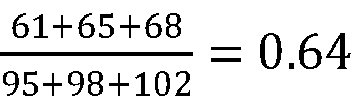
- Such current section average velocity information and the velocity ratio information may be generated by using each of cameras installed in each of points dividing each of sections. Specifically, the
center server 200 may be able to (i) specify each of passing vehicles by using information on their registration numbers and their exteriors, (ii) calculate times spent for covering each of the sections in order to measure each of their velocities, and thus (iii) generate section average velocity information on each of the sections, including the current section average information. For the velocity ratio information of the interfering vehicle, general velocity ratio information for each of passing vehicles may have been prepared for each of the sections by using each of piece of the section average velocity information. Since the general velocity ratio information for all of the passing vehicles is prepared, if thecenter server 200 acquires information for specifying the interfering vehicle among the passing vehicles, such as the vehicle identifier information and the vehicle exterior information, from theV2X communication module 130, the velocity ratio information for the interfering vehicle, among the general velocity ratio information, may be selected and transmitted to thecomputing device 100. - After such current velocity information is acquired, it can be referred to along with the acceleration capability information, to thereby generate the potential interference prediction model.
- The (2-1)-st example embodiment is as shown above. Below, the (2-2)-nd example embodiment corresponding to the
image processing module 140 will be presented. - For the (2-2)-nd example embodiment, the 2-nd
neural network 142 may have been configured to have one more node for outputting the current velocity information in the (2-2)-nd FC layer, and may have been trained by using a modified 2-nd GT including GT current velocity information. In this case, thecomputing device 100 may instruct the 2-nd neural network included in theimage processing module 140 to apply the 2-nd neural network operations to the modeling image, to thereby generate the current velocity information along with the acceleration capability information and then to thereby transmit the current velocity information and the acceleration capability information to theplanning module 150. Thereafter, the computing device may instruct theplanning module 150 to generate the potential interference prediction model by referring to the current velocity information and the acceleration capability information. - For the (2-3)-rd example embodiment, the
V2X communication module 130 may be mainly used to acquire the acceleration capability information and the current velocity information. That is, thecomputing device 100 may instruct theV2X communication module 130 to communicate with thecenter server 200 to acquire the acceleration capability information, the velocity ratio information and the current section average velocity information. Thereafter, thecomputing device 100 may instruct the V2X communication module to transmit the acceleration capability information of the interfering vehicle and the current velocity information of the interfering vehicle calculated by using the velocity ratio information and the current section average velocity information, and may instruct theplanning module 150 to generate the potential interference prediction model by referring to the acceleration capability information and the current velocity information. In this example embodiment, thecenter server 200 may acquire information on categories and loadages of the passing vehicles including the interfering vehicle by using each of the cameras installed in points between each of the sections, to thereby generate the acceleration capability information, and then to thereby transmit it to thecomputing device 100. - After the acceleration capability information and the current velocity information are acquired by using methods corresponding to the example embodiments, the
computing device 100 may instruct theplanning module 150 to generate estimated velocity range information by referring to (i) a TTC value corresponding to a time for the subject autonomous vehicle to evade the potential interfering action, (ii) the acceleration capability information and (iii) the current velocity information, to thereby generate the potential interference prediction model including the estimated velocity range information.

- The estimated velocity range information, including information on a largest velocity and a smallest velocity of the interfering vehicle in a range of the time corresponding to the TTC value, can be generated by following above formula, and it can be used for generating the potential interference prediction model. Thereafter, the potential interfering action, corresponding to a velocity of the interfering vehicle driving in front of the subject autonomous vehicle, can be predicted by using the potential interference prediction model.
- After the potential interfering action is predicted, the
computing device 100 may instruct theplanning module 150 to generate updated optimized route information by modifying the current optimized route information, in order to evade the potential interfering action. As an example, if the potential interfering action indicates that the interfering vehicle may move slowly in front of the subject autonomous vehicle, in the same lane. In this case, thecomputing device 100 may instruct theplanning module 150 to acquire lane average velocity information of at least one surrounding lane located in at least one of a left side and a right side of a current lane including the subject autonomous vehicle. Such lane average velocity information may have been acquired by using the cameras located between each of the sections, and transmitted from thecenter server 200 to theplanning module 150, through theV2X communication module 130. - Thereafter, the
computing device 100 may instruct theplanning module 150 to modify the current optimized route information in order to add an evading action, to be executed in correspondence with the surrounding lane in order to evade the potential interfering action, by referring to the lane average velocity information, to thereby generate the updated optimized route information. The lane average velocity information may have been used for finding a better lane for passing. To explain such usage of the lane average velocity information,Fig. 5 will be referred to. -
Fig. 5 is a drawing schematically illustrating how to modify current optimized route information to be used for performing the method for planning the autonomous driving by using the V2X communication and the image processing under the road circumstance where both the vehicles capable of the V2X communication and the vehicles incapable of the V2X communication exist in accordance with one example embodiment of the present disclosure. - By referring to
Fig. 5 , it can be seen that an average velocity of a lane on the left is larger than that of a lane on the right. In this case, selecting the lane on the left will be more suitable for passing. Thus, the lane on the left will be selected, and the evading action by using the lane on the left will be added to the current optimized route information, to thereby generate the updated optimized route information. - By using such planning method, even under a road circumstance where both vehicles capable of the V2X communication and vehicles incapable of the V2X communication exist, the autonomous driving may be performed properly.
- The present disclosure has an effect of providing a method for planning an autonomous driving by using a V2X communication and an image processing to allow the autonomous driving to be performed more safely.
- The embodiments of the present disclosure as explained above can be implemented in a form of executable program command through a variety of computer means recordable to computer readable media. The computer readable media may include solely or in combination, program commands, data files, and data structures. The program commands recorded to the media may be components specially designed for the present disclosure or may be usable to a skilled human in a field of computer software. Computer readable media include magnetic media such as hard disk, floppy disk, and magnetic tape, optical media such as CD-ROM and DVD, magneto-optical media such as floptical disk and hardware devices such as ROM, RAM, and flash memory specially designed to store and carry out program commands. Program commands include not only a machine language code made by a compiler but also a high level language code that can be executed by a computer using an interpreter, etc. The hardware device can work as more than a software module to perform the process in accordance with the present disclosure and they can do the same in the opposite case.
- As seen above, the present disclosure has been explained by specific matters such as detailed components, limited embodiments, and drawings. They have been provided only to help more general understanding of the present disclosure. It, however, will be understood by those skilled in the art that various changes and modification may be made from the description without departing from the scope of the disclosure as defined in the following claims.
- Accordingly, the thought of the present disclosure must not be confined to the explained embodiments, but to the following patent claims.
Claims (8)
- A method for planning an autonomous driving of a subject autonomous vehicle by using a Vehicle-to-everything (V2X) communication and an image processing under a road circumstance where both vehicles capable of the V2X communication and vehicles incapable of the V2X communication exist, comprising steps of:(a) a computing device instructing a planning module to acquire recognition information on at least part of surrounding vehicles including at least part of (i) a first group including one or more first vehicles which are capable of a V2X communication and are located closer than a threshold distance from the subject autonomous vehicle and (ii) a second group including one or more second vehicles which are incapable of the V2X communication and are located closer than the threshold distance from the subject autonomous vehicle, by interworking with at least one of a V2X communication module and an image processing module;(b) the computing device instructing the planning module to select at least one interfering vehicle among the surrounding vehicles, whose probability of obstructing the subject autonomous vehicle is larger than a threshold probability, by referring to a current optimized route information of the subject autonomous vehicle and the recognition information; and(c) the computing device instructing the planning module to generate a potential interference prediction model on the interfering vehicle by interworking with at least one of the V2X communication module and the image processing module, and to modify the current optimized route information in order to evade a potential interfering action of the interfering vehicle, which is estimated by using the potential interference prediction model, to thereby generate updated optimized route information of the subject autonomous vehicle, the computing device (100) being included in the subject autonomous vehicle, or being included in a control server configured to control the subject autonomous vehicle through a remote wireless communication,, wherein, at the step of (c), the computing device, when the interfering vehicle belongs to the second group, (i) instructs the image processing module (i-1) to acquire a modeling image including the interfering vehicle through at least one camera installed to the subject autonomous vehicle and (i-2) to apply one or more neural network operations (2-nd, 142) to the modeling image, to thereby generate acceleration capability information of the interfering vehicle, and then to thereby transmit the acceleration capability information to the planning module, and (ii) instructs the planning module to generate the potential interference prediction model by referring to the acceleration capability information and current velocity information of the interfering vehicle acquired by using at least one of the image processing module and the V2X communication module characterized in that: the current velocity information is generated by referring to velocity ratio information of the interfering vehicle and current section average velocity information, wherein the velocity ratio information has been generated by comparing each of average velocities for each of past sections of a road, where the surrounding vehicles and the subject autonomous vehicle have been driving, with each of velocities of the interfering vehicle in each of the past sections, and transmitted from a center server to the V2X communication module, and the current section average velocity information has been generated by calculating an average velocity of vehicles in a current section of a road where the surrounding vehicles and the subject autonomous vehicle are driving currently, and transmitted from the center server to the V2X communication module, wherein, at the step of (c), the computing device instructs a neural network (2-nd, 142) included in the image processing module to apply one or more first neural network operations ((2-1)-st, 142-1), among the neural network operations (2-nd, 142), to the modeling image by additionally referring to a self-vehicle velocity information of the subject autonomous vehicle, to thereby generate (i) relative velocity information of the interfering vehicle in relation to the subject autonomous vehicle, (ii) category information corresponding to a class of the interfering vehicle, and (iii) acceleration variable information corresponding to at least part of a mass and a volume of the interfering vehicle, and instructs the neural network (2-nd, 142) to apply one or more second neural network operations ((2-2) - nd, 142-2), among neural network operations (2-nd, 142), to a concatenated vector including the relative velocity information, the category information and the acceleration variable information as its components, to thereby generate the acceleration capability information of the interfering vehicle, and wherein, at the step of (c), the computing device subsequently instructs the neural network (2-nd, 142) to apply the second neural network operations ((2-2)-nd, 142-2), to the concatenated vector, further including current section average velocity information on an average velocity of vehicles in a current section of a road where the surrounding vehicles and the subject autonomous vehicle are driving currently, to thereby generate the acceleration capability information.
- The method of Claim 1, wherein the computing device instructs the planning module to generate estimated velocity range information by referring to (i) a TTC value corresponding to a time for the subject autonomous vehicle to evade the potential interfering action, (ii) the acceleration capability information and (iii) the current velocity information, to thereby generate the potential interference prediction model including the estimated velocity range information.
- A method according to claim 1, wherein, at the step of (c), the computing device instructs the planning module to acquire lane average velocity information of at least one surrounding lane located in at least one of a left side and a right side of a current lane including the subject autonomous vehicle, and to modify the current optimized route information in order to add an evading action, to be executed in correspondence with the surrounding lane in order to evade the potential interfering action, by referring to the lane average velocity information, to thereby generate the updated optimized route information.
- The method according to claim 1, wherein, at the step of (a), the computing device instructs a first neural network included in the image processing module to acquire at least one circumstance image, corresponding to at least one direction from the subject autonomous vehicle, through at least one camera installed to the subject autonomous vehicle, and to apply one or more first neural network operations to the circumstance image, to thereby generate the recognition information and then to thereby transmit the recognition information to the planning module, wherein the recognition information includes at least part of (i) vehicle identifier information, (ii) vehicle exterior information, and (iii) vehicle relative location information from the subject autonomous vehicle.
- The method of Claim 4, wherein, at the step of (b), the computing device instructs the planning module to (i) generate a scheduled direction vector by using scheduled direction information on a direction to which the subject autonomous vehicle is planned to move in a threshold time and generate one or more relative location vectors by using the vehicle relative location information corresponding to at least part of the surrounding vehicles, (ii) generate each of similarity scores between the scheduled direction vector and each of the relative location vectors, and (iii) select at least one specific surrounding vehicle, among the surrounding vehicles, as the interfering vehicle, whose specific similarity score is larger than a threshold similarity score.
- The method of Claim 1, wherein, at the step of (b), the computing device instructs the planning module to select at least one specific surrounding vehicle, whose corresponding partial image is located in a current lane region, corresponding to a current lane of a road including the subject autonomous vehicle, of the circumstance image, as the interfering vehicle, by referring to information on locations, of bounding boxes including the surrounding vehicles, on the circumstance image, which is acquired by using the image processing module.
- The method of Claim 1, wherein, at the step of (c), the computing device, if the interfering vehicle belongs to the first group, instructs the V2X communication module to acquire scheduled route information of the interfering vehicle by communicating with the interfering vehicle, and instructs the planning module to generate the potential interference prediction model by referring to the scheduled route information.
- A computing device for planning an autonomous driving of a subject autonomous vehicle by using a Vehicle-to-everything (V2X) communication and an image processing under a road circumstance where both vehicles capable of the V2X communication and vehicles incapable of the V2X communication exist, comprising:at least one memory that stores instructions; andat least one processor configured to execute the instructions to perform the steps the method of either of the preceding claims.
Applications Claiming Priority (2)
| Application Number | Priority Date | Filing Date | Title |
|---|---|---|---|
| US201962799207P | 2019-01-31 | 2019-01-31 | |
| US16/724,475 US10861183B2 (en) | 2019-01-31 | 2019-12-23 | Method and device for short-term path planning of autonomous driving through information fusion by using V2X communication and image processing |
Publications (3)
| Publication Number | Publication Date |
|---|---|
| EP3693944A1 EP3693944A1 (en) | 2020-08-12 |
| EP3693944C0 EP3693944C0 (en) | 2024-08-07 |
| EP3693944B1 true EP3693944B1 (en) | 2024-08-07 |
Family
ID=69191915
Family Applications (1)
| Application Number | Title | Priority Date | Filing Date |
|---|---|---|---|
| EP20153511.9A Active EP3693944B1 (en) | 2019-01-31 | 2020-01-24 | Method and device for short-term path planning of autonomous driving through information fusion by using v2x communication and image processing |
Country Status (5)
| Country | Link |
|---|---|
| US (1) | US10861183B2 (en) |
| EP (1) | EP3693944B1 (en) |
| JP (1) | JP6916551B2 (en) |
| KR (1) | KR102306939B1 (en) |
| CN (1) | CN111506058B (en) |
Families Citing this family (20)
| Publication number | Priority date | Publication date | Assignee | Title |
|---|---|---|---|---|
| US12307902B2 (en) * | 2020-04-21 | 2025-05-20 | Qualcomm Incorporated | Cluster-based approach to positioning of vehicles in vehicle platooning or autonomous trucking |
| WO2022097869A1 (en) * | 2020-11-05 | 2022-05-12 | 엘지전자 주식회사 | Method for controlling driving of v2x vehicle by first device in wireless communication system supporting sidelink, and device therefor |
| CN112185123A (en) * | 2020-11-06 | 2021-01-05 | 广州南洋理工职业学院 | Vehicle safety interval early warning method based on Internet of vehicles |
| US12183110B2 (en) | 2020-11-30 | 2024-12-31 | At&T Intellectual Property I, L.P. | Autonomous aerial vehicle projection zone selection |
| US11443518B2 (en) | 2020-11-30 | 2022-09-13 | At&T Intellectual Property I, L.P. | Uncrewed aerial vehicle shared environment privacy and security |
| US11726475B2 (en) | 2020-11-30 | 2023-08-15 | At&T Intellectual Property I, L.P. | Autonomous aerial vehicle airspace claiming and announcing |
| US11797896B2 (en) | 2020-11-30 | 2023-10-24 | At&T Intellectual Property I, L.P. | Autonomous aerial vehicle assisted viewing location selection for event venue |
| CN112758105B (en) * | 2020-12-30 | 2022-03-22 | 上海汽车集团股份有限公司 | A method, device and system for controlling the following driving of an automatic driving fleet |
| CN114818844B (en) * | 2021-01-27 | 2025-06-24 | 广州视源电子科技股份有限公司 | Pulmonary embolism identification device, terminal device and storage medium based on parameter sharing |
| DE102021201063B4 (en) | 2021-02-04 | 2024-07-11 | Volkswagen Aktiengesellschaft | Method for operating a system for an at least partially assisted motor vehicle, computer program product and system |
| JP7347461B2 (en) * | 2021-03-05 | 2023-09-20 | トヨタ自動車株式会社 | Automatic parking system and automatic parking system control method |
| CN113442950B (en) * | 2021-08-31 | 2021-11-23 | 国汽智控(北京)科技有限公司 | Automatic driving control method, device and equipment based on multiple vehicles |
| CN115973186A (en) * | 2021-10-14 | 2023-04-18 | 云控智行科技有限公司 | Lane selection method and device based on automatic driving |
| TWI790825B (en) | 2021-11-19 | 2023-01-21 | 財團法人工業技術研究院 | Safe following distance estimation stystem and estimation method thereof |
| CN114283574B (en) * | 2021-12-29 | 2022-10-28 | 湖南师范大学 | Vehicle scheduling evaluation method based on convolution strategy |
| CN115019503B (en) * | 2022-05-12 | 2023-06-16 | 东风汽车集团股份有限公司 | Information sharing-based space track distribution method under mixed traffic flow of aerocar |
| CN117341723A (en) * | 2022-06-28 | 2024-01-05 | 深圳市中兴微电子技术有限公司 | Automatic driving method and system |
| CN116774590B (en) * | 2023-08-17 | 2023-11-07 | 山东金彭新能源科技有限公司 | Adaptive regulation and control method and system for influencing interference |
| IT202300026151A1 (en) * | 2023-12-06 | 2025-06-06 | Fiat Ricerche | VEHICLE DRIVING ASSISTANCE BASED ON V2X COMMUNICATION IN A VIRTUAL DRIVING SCENE |
| IT202300026163A1 (en) * | 2023-12-06 | 2025-06-06 | Fiat Ricerche | V2X COMMUNICATION BASED VEHICLE DRIVING ASSISTANCE WITH REALISTIC MAP REPRESENTATION |
Citations (5)
| Publication number | Priority date | Publication date | Assignee | Title |
|---|---|---|---|---|
| EP3272611A1 (en) * | 2015-04-21 | 2018-01-24 | Panasonic Intellectual Property Management Co., Ltd. | Information processing system, information processing method, and program |
| US20180022348A1 (en) * | 2017-09-15 | 2018-01-25 | GM Global Technology Operations LLC | Methods and systems for determining lane health from an autonomous vehicle |
| US20180061253A1 (en) * | 2016-09-01 | 2018-03-01 | Samsung Electronics Co., Ltd. | Autonomous driving method and apparatus |
| US20180082137A1 (en) * | 2016-09-19 | 2018-03-22 | Nec Laboratories America, Inc. | Advanced driver-assistance system |
| US20180232585A1 (en) * | 2017-02-16 | 2018-08-16 | Samsung Electronics Co., Ltd. | Autonomous vehicle control method and apparatus |
Family Cites Families (20)
| Publication number | Priority date | Publication date | Assignee | Title |
|---|---|---|---|---|
| JP2001030798A (en) * | 1999-07-26 | 2001-02-06 | Mazda Motor Corp | Vehicle travel control device |
| JP4239771B2 (en) * | 2003-09-18 | 2009-03-18 | 日産自動車株式会社 | VEHICLE DRIVE OPERATION ASSISTANCE DEVICE AND VEHICLE HAVING VEHICLE DRIVE OPERATION ASSISTANCE DEVICE |
| JP4525670B2 (en) * | 2006-11-20 | 2010-08-18 | トヨタ自動車株式会社 | Travel control plan generation system |
| JP2011227582A (en) * | 2010-04-15 | 2011-11-10 | Toyota Motor Corp | Vehicle collision prediction apparatus |
| US9253753B2 (en) * | 2012-04-24 | 2016-02-02 | Zetta Research And Development Llc-Forc Series | Vehicle-to-vehicle safety transceiver using time slots |
| JP6155973B2 (en) * | 2013-08-27 | 2017-07-05 | 株式会社デンソー | Driving support device and driving support method |
| KR102278387B1 (en) * | 2015-07-07 | 2021-07-16 | 주식회사 만도 | Distance calculating apparatus and distance calculating method and driving assist apparatus and driving assist system |
| US9767687B2 (en) * | 2015-09-11 | 2017-09-19 | Sony Corporation | System and method for driving assistance along a path |
| JP6657789B2 (en) * | 2015-10-29 | 2020-03-04 | 株式会社リコー | Image processing device, imaging device, device control system, frequency distribution image generation method, and program |
| CN105976631A (en) * | 2015-11-06 | 2016-09-28 | 乐卡汽车智能科技(北京)有限公司 | Vehicle data processing method and vehicle terminal |
| US9922553B2 (en) * | 2015-12-22 | 2018-03-20 | Intel Corporation | Vehicle assistance systems and methods utilizing vehicle to vehicle communications |
| US10482226B1 (en) * | 2016-01-22 | 2019-11-19 | State Farm Mutual Automobile Insurance Company | System and method for autonomous vehicle sharing using facial recognition |
| JP6688655B2 (en) * | 2016-03-31 | 2020-04-28 | 株式会社Subaru | Vehicle condition monitoring device |
| JP6616275B2 (en) * | 2016-12-15 | 2019-12-04 | 株式会社Soken | Driving assistance device |
| JP6733535B2 (en) * | 2016-12-19 | 2020-08-05 | 株式会社デンソー | Driving support device |
| JP2018195301A (en) * | 2017-05-15 | 2018-12-06 | キヤノン株式会社 | Control device and control method |
| KR102412615B1 (en) * | 2017-09-07 | 2022-06-23 | 삼성전자주식회사 | Method and apparatus for wireless communication considering collisions among device to device transmissions |
| KR102414456B1 (en) * | 2017-10-23 | 2022-06-30 | 현대자동차주식회사 | Dialogue processing apparatus, vehicle having the same and accident information processing method |
| KR102445365B1 (en) * | 2018-03-19 | 2022-09-20 | 현대자동차주식회사 | Dialogue processing apparatus, vehicle having the same and dialogue processing method |
| US11113971B2 (en) * | 2018-06-12 | 2021-09-07 | Baidu Usa Llc | V2X communication-based vehicle lane system for autonomous vehicles |
-
2019
- 2019-12-23 US US16/724,475 patent/US10861183B2/en active Active
-
2020
- 2020-01-06 KR KR1020200001725A patent/KR102306939B1/en active Active
- 2020-01-13 CN CN202010034290.7A patent/CN111506058B/en active Active
- 2020-01-17 JP JP2020005636A patent/JP6916551B2/en active Active
- 2020-01-24 EP EP20153511.9A patent/EP3693944B1/en active Active
Patent Citations (5)
| Publication number | Priority date | Publication date | Assignee | Title |
|---|---|---|---|---|
| EP3272611A1 (en) * | 2015-04-21 | 2018-01-24 | Panasonic Intellectual Property Management Co., Ltd. | Information processing system, information processing method, and program |
| US20180061253A1 (en) * | 2016-09-01 | 2018-03-01 | Samsung Electronics Co., Ltd. | Autonomous driving method and apparatus |
| US20180082137A1 (en) * | 2016-09-19 | 2018-03-22 | Nec Laboratories America, Inc. | Advanced driver-assistance system |
| US20180232585A1 (en) * | 2017-02-16 | 2018-08-16 | Samsung Electronics Co., Ltd. | Autonomous vehicle control method and apparatus |
| US20180022348A1 (en) * | 2017-09-15 | 2018-01-25 | GM Global Technology Operations LLC | Methods and systems for determining lane health from an autonomous vehicle |
Also Published As
| Publication number | Publication date |
|---|---|
| US10861183B2 (en) | 2020-12-08 |
| JP6916551B2 (en) | 2021-08-11 |
| US20200250848A1 (en) | 2020-08-06 |
| EP3693944C0 (en) | 2024-08-07 |
| CN111506058A (en) | 2020-08-07 |
| KR102306939B1 (en) | 2021-10-05 |
| JP2020126619A (en) | 2020-08-20 |
| CN111506058B (en) | 2023-08-22 |
| EP3693944A1 (en) | 2020-08-12 |
| KR20200096115A (en) | 2020-08-11 |
Similar Documents
| Publication | Publication Date | Title |
|---|---|---|
| US10861183B2 (en) | Method and device for short-term path planning of autonomous driving through information fusion by using V2X communication and image processing | |
| CN110796856B (en) | Vehicle lane change intention prediction method and training method of lane change intention prediction network | |
| EP3822852B1 (en) | Method, apparatus, computer storage medium and program for training a trajectory planning model | |
| CN110007675B (en) | Vehicle automatic driving decision-making system based on driving situation map and training set preparation method based on unmanned aerial vehicle | |
| EP3690730B1 (en) | Learning device for supporting safer autonomous driving without danger of accident by estimating motions of surrounding objects through fusion of information from multiple sources | |
| US10919543B2 (en) | Learning method and learning device for determining whether to switch mode of vehicle from manual driving mode to autonomous driving mode by performing trajectory-based behavior analysis on recent driving route | |
| Niranjan et al. | Deep learning based object detection model for autonomous driving research using carla simulator | |
| EP3638981B1 (en) | Fusion framework of navigation information for autonomous navigation | |
| US10796206B2 (en) | Method for integrating driving images acquired from vehicles performing cooperative driving and driving image integrating device using same | |
| CN112163446B (en) | Obstacle detection method and device, electronic equipment and storage medium | |
| CN109491375A (en) | The path planning based on Driving Scene for automatic driving vehicle | |
| CN111507369B (en) | Autonomous vehicle space learning method and device, testing method and device | |
| DE112023001847T5 (en) | A SAFE AND SCALABLE MODEL FOR CULTURALLY SENSITIVE DRIVING BY AUTOMATED VEHICLES USING A PROBABILISTIC ARCHITECTURE | |
| US20230071810A1 (en) | System and method for providing spatiotemporal costmap inference for model predictive control | |
| CN110288835A (en) | A Real-time Recognition Method of Surrounding Vehicle Behavior Based on Kinematics Prediction and Compensation Mechanism | |
| Lei et al. | A bio-inspired neural network approach to robot navigation and mapping with nature-inspired algorithms | |
| EP3690756A1 (en) | Learning method and learning device for updating hd map by reconstructing 3d space by using depth estimation information and class information on each object, which have been acquired through v2x information integration technique, and testing method and testing device using the same | |
| US20230281424A1 (en) | Method for Extracting Features from Data of Traffic Scenario Based on Graph Neural Network | |
| CN115230719A (en) | A driving trajectory planning method and device | |
| DE102023133455A1 (en) | Method for detecting lane segments to create high-resolution maps | |
| DE102023136900A1 (en) | SYSTEMS AND METHODS FOR HANDLING TRAFFIC SIGNS | |
| DE102024101906A1 (en) | METHODS AND SYSTEMS FOR LONG-TERM TRAJECTORY FORECASTING BY EXTENDING A FORECAST HORIZON | |
| Guo et al. | Self-defensive coordinated maneuvering of an intelligent vehicle platoon in mixed traffic | |
| Tsiakas et al. | Leveraging multimodal sensing and topometric mapping for human-like autonomous navigation in complex environments | |
| Wan et al. | Fusing onboard modalities with V2V information for autonomous driving |
Legal Events
| Date | Code | Title | Description |
|---|---|---|---|
| PUAI | Public reference made under article 153(3) epc to a published international application that has entered the european phase |
Free format text: ORIGINAL CODE: 0009012 |
|
| STAA | Information on the status of an ep patent application or granted ep patent |
Free format text: STATUS: REQUEST FOR EXAMINATION WAS MADE |
|
| 17P | Request for examination filed |
Effective date: 20200124 |
|
| AK | Designated contracting states |
Kind code of ref document: A1 Designated state(s): AL AT BE BG CH CY CZ DE DK EE ES FI FR GB GR HR HU IE IS IT LI LT LU LV MC MK MT NL NO PL PT RO RS SE SI SK SM TR |
|
| AX | Request for extension of the european patent |
Extension state: BA ME |
|
| RBV | Designated contracting states (corrected) |
Designated state(s): AL AT BE BG CH CY CZ DE DK EE ES FI FR GB GR HR HU IE IS IT LI LT LU LV MC MK MT NL NO PL PT RO RS SE SI SK SM TR |
|
| STAA | Information on the status of an ep patent application or granted ep patent |
Free format text: STATUS: EXAMINATION IS IN PROGRESS |
|
| 17Q | First examination report despatched |
Effective date: 20230209 |
|
| GRAP | Despatch of communication of intention to grant a patent |
Free format text: ORIGINAL CODE: EPIDOSNIGR1 |
|
| STAA | Information on the status of an ep patent application or granted ep patent |
Free format text: STATUS: GRANT OF PATENT IS INTENDED |
|
| RIC1 | Information provided on ipc code assigned before grant |
Ipc: G08G 1/01 20060101ALI20240212BHEP Ipc: G08G 1/017 20060101ALI20240212BHEP Ipc: G08G 1/052 20060101ALI20240212BHEP Ipc: B60W 30/095 20120101ALI20240212BHEP Ipc: B60W 30/18 20120101ALI20240212BHEP Ipc: B60W 60/00 20200101ALI20240212BHEP Ipc: G08G 1/16 20060101AFI20240212BHEP |
|
| INTG | Intention to grant announced |
Effective date: 20240315 |
|
| GRAS | Grant fee paid |
Free format text: ORIGINAL CODE: EPIDOSNIGR3 |
|
| GRAA | (expected) grant |
Free format text: ORIGINAL CODE: 0009210 |
|
| STAA | Information on the status of an ep patent application or granted ep patent |
Free format text: STATUS: THE PATENT HAS BEEN GRANTED |
|
| AK | Designated contracting states |
Kind code of ref document: B1 Designated state(s): AL AT BE BG CH CY CZ DE DK EE ES FI FR GB GR HR HU IE IS IT LI LT LU LV MC MK MT NL NO PL PT RO RS SE SI SK SM TR |
|
| REG | Reference to a national code |
Ref country code: GB Ref legal event code: FG4D |
|
| REG | Reference to a national code |
Ref country code: CH Ref legal event code: EP |
|
| REG | Reference to a national code |
Ref country code: IE Ref legal event code: FG4D |
|
| REG | Reference to a national code |
Ref country code: DE Ref legal event code: R096 Ref document number: 602020035136 Country of ref document: DE |
|
| U01 | Request for unitary effect filed |
Effective date: 20240904 |
|
| U07 | Unitary effect registered |
Designated state(s): AT BE BG DE DK EE FI FR IT LT LU LV MT NL PT RO SE SI Effective date: 20240917 |
|
| PG25 | Lapsed in a contracting state [announced via postgrant information from national office to epo] |
Ref country code: NO Free format text: LAPSE BECAUSE OF FAILURE TO SUBMIT A TRANSLATION OF THE DESCRIPTION OR TO PAY THE FEE WITHIN THE PRESCRIBED TIME-LIMIT Effective date: 20241107 |
|
| U20 | Renewal fee for the european patent with unitary effect paid |
Year of fee payment: 6 Effective date: 20241210 |
|
| PG25 | Lapsed in a contracting state [announced via postgrant information from national office to epo] |
Ref country code: PL Free format text: LAPSE BECAUSE OF FAILURE TO SUBMIT A TRANSLATION OF THE DESCRIPTION OR TO PAY THE FEE WITHIN THE PRESCRIBED TIME-LIMIT Effective date: 20240807 Ref country code: GR Free format text: LAPSE BECAUSE OF FAILURE TO SUBMIT A TRANSLATION OF THE DESCRIPTION OR TO PAY THE FEE WITHIN THE PRESCRIBED TIME-LIMIT Effective date: 20241108 |
|
| PG25 | Lapsed in a contracting state [announced via postgrant information from national office to epo] |
Ref country code: IS Free format text: LAPSE BECAUSE OF FAILURE TO SUBMIT A TRANSLATION OF THE DESCRIPTION OR TO PAY THE FEE WITHIN THE PRESCRIBED TIME-LIMIT Effective date: 20241207 |
|
| PG25 | Lapsed in a contracting state [announced via postgrant information from national office to epo] |
Ref country code: HR Free format text: LAPSE BECAUSE OF FAILURE TO SUBMIT A TRANSLATION OF THE DESCRIPTION OR TO PAY THE FEE WITHIN THE PRESCRIBED TIME-LIMIT Effective date: 20240807 |
|
| PG25 | Lapsed in a contracting state [announced via postgrant information from national office to epo] |
Ref country code: ES Free format text: LAPSE BECAUSE OF FAILURE TO SUBMIT A TRANSLATION OF THE DESCRIPTION OR TO PAY THE FEE WITHIN THE PRESCRIBED TIME-LIMIT Effective date: 20240807 Ref country code: RS Free format text: LAPSE BECAUSE OF FAILURE TO SUBMIT A TRANSLATION OF THE DESCRIPTION OR TO PAY THE FEE WITHIN THE PRESCRIBED TIME-LIMIT Effective date: 20241107 |
|
| PG25 | Lapsed in a contracting state [announced via postgrant information from national office to epo] |
Ref country code: RS Free format text: LAPSE BECAUSE OF FAILURE TO SUBMIT A TRANSLATION OF THE DESCRIPTION OR TO PAY THE FEE WITHIN THE PRESCRIBED TIME-LIMIT Effective date: 20241107 Ref country code: PL Free format text: LAPSE BECAUSE OF FAILURE TO SUBMIT A TRANSLATION OF THE DESCRIPTION OR TO PAY THE FEE WITHIN THE PRESCRIBED TIME-LIMIT Effective date: 20240807 Ref country code: NO Free format text: LAPSE BECAUSE OF FAILURE TO SUBMIT A TRANSLATION OF THE DESCRIPTION OR TO PAY THE FEE WITHIN THE PRESCRIBED TIME-LIMIT Effective date: 20241107 Ref country code: IS Free format text: LAPSE BECAUSE OF FAILURE TO SUBMIT A TRANSLATION OF THE DESCRIPTION OR TO PAY THE FEE WITHIN THE PRESCRIBED TIME-LIMIT Effective date: 20241207 Ref country code: HR Free format text: LAPSE BECAUSE OF FAILURE TO SUBMIT A TRANSLATION OF THE DESCRIPTION OR TO PAY THE FEE WITHIN THE PRESCRIBED TIME-LIMIT Effective date: 20240807 Ref country code: GR Free format text: LAPSE BECAUSE OF FAILURE TO SUBMIT A TRANSLATION OF THE DESCRIPTION OR TO PAY THE FEE WITHIN THE PRESCRIBED TIME-LIMIT Effective date: 20241108 Ref country code: ES Free format text: LAPSE BECAUSE OF FAILURE TO SUBMIT A TRANSLATION OF THE DESCRIPTION OR TO PAY THE FEE WITHIN THE PRESCRIBED TIME-LIMIT Effective date: 20240807 |
|
| PG25 | Lapsed in a contracting state [announced via postgrant information from national office to epo] |
Ref country code: SM Free format text: LAPSE BECAUSE OF FAILURE TO SUBMIT A TRANSLATION OF THE DESCRIPTION OR TO PAY THE FEE WITHIN THE PRESCRIBED TIME-LIMIT Effective date: 20240807 |
|
| PG25 | Lapsed in a contracting state [announced via postgrant information from national office to epo] |
Ref country code: CZ Free format text: LAPSE BECAUSE OF FAILURE TO SUBMIT A TRANSLATION OF THE DESCRIPTION OR TO PAY THE FEE WITHIN THE PRESCRIBED TIME-LIMIT Effective date: 20240807 |
|
| PG25 | Lapsed in a contracting state [announced via postgrant information from national office to epo] |
Ref country code: SK Free format text: LAPSE BECAUSE OF FAILURE TO SUBMIT A TRANSLATION OF THE DESCRIPTION OR TO PAY THE FEE WITHIN THE PRESCRIBED TIME-LIMIT Effective date: 20240807 |
|
| PLBE | No opposition filed within time limit |
Free format text: ORIGINAL CODE: 0009261 |
|
| STAA | Information on the status of an ep patent application or granted ep patent |
Free format text: STATUS: NO OPPOSITION FILED WITHIN TIME LIMIT |
|
| 26N | No opposition filed |
Effective date: 20250508 |
|
| REG | Reference to a national code |
Ref country code: CH Ref legal event code: PL |
|
| PG25 | Lapsed in a contracting state [announced via postgrant information from national office to epo] |
Ref country code: MC Free format text: LAPSE BECAUSE OF FAILURE TO SUBMIT A TRANSLATION OF THE DESCRIPTION OR TO PAY THE FEE WITHIN THE PRESCRIBED TIME-LIMIT Effective date: 20240807 |
|
| GBPC | Gb: european patent ceased through non-payment of renewal fee |
Effective date: 20250124 |
|
| PG25 | Lapsed in a contracting state [announced via postgrant information from national office to epo] |
Ref country code: GB Free format text: LAPSE BECAUSE OF NON-PAYMENT OF DUE FEES Effective date: 20250124 |
|
| PG25 | Lapsed in a contracting state [announced via postgrant information from national office to epo] |
Ref country code: CH Free format text: LAPSE BECAUSE OF NON-PAYMENT OF DUE FEES Effective date: 20250131 |
|
| PG25 | Lapsed in a contracting state [announced via postgrant information from national office to epo] |
Ref country code: IE Free format text: LAPSE BECAUSE OF NON-PAYMENT OF DUE FEES Effective date: 20250124 |
|
| U20 | Renewal fee for the european patent with unitary effect paid |
Year of fee payment: 7 Effective date: 20260129 |