EP3693613A1 - Rotating diffuser in centrifugal compressor - Google Patents
Rotating diffuser in centrifugal compressor Download PDFInfo
- Publication number
- EP3693613A1 EP3693613A1 EP20156417.6A EP20156417A EP3693613A1 EP 3693613 A1 EP3693613 A1 EP 3693613A1 EP 20156417 A EP20156417 A EP 20156417A EP 3693613 A1 EP3693613 A1 EP 3693613A1
- Authority
- EP
- European Patent Office
- Prior art keywords
- wall
- axis
- centrifugal compressor
- opening
- piece
- Prior art date
- Legal status (The legal status is an assumption and is not a legal conclusion. Google has not performed a legal analysis and makes no representation as to the accuracy of the status listed.)
- Granted
Links
Images



Classifications
-
- F—MECHANICAL ENGINEERING; LIGHTING; HEATING; WEAPONS; BLASTING
- F04—POSITIVE - DISPLACEMENT MACHINES FOR LIQUIDS; PUMPS FOR LIQUIDS OR ELASTIC FLUIDS
- F04D—NON-POSITIVE-DISPLACEMENT PUMPS
- F04D29/00—Details, component parts, or accessories
- F04D29/40—Casings; Connections of working fluid
- F04D29/42—Casings; Connections of working fluid for radial or helico-centrifugal pumps
- F04D29/44—Fluid-guiding means, e.g. diffusers
- F04D29/441—Fluid-guiding means, e.g. diffusers especially adapted for elastic fluid pumps
- F04D29/442—Fluid-guiding means, e.g. diffusers especially adapted for elastic fluid pumps rotating diffusers
-
- F—MECHANICAL ENGINEERING; LIGHTING; HEATING; WEAPONS; BLASTING
- F04—POSITIVE - DISPLACEMENT MACHINES FOR LIQUIDS; PUMPS FOR LIQUIDS OR ELASTIC FLUIDS
- F04D—NON-POSITIVE-DISPLACEMENT PUMPS
- F04D17/00—Radial-flow pumps, e.g. centrifugal pumps; Helico-centrifugal pumps
- F04D17/08—Centrifugal pumps
- F04D17/10—Centrifugal pumps for compressing or evacuating
-
- F—MECHANICAL ENGINEERING; LIGHTING; HEATING; WEAPONS; BLASTING
- F04—POSITIVE - DISPLACEMENT MACHINES FOR LIQUIDS; PUMPS FOR LIQUIDS OR ELASTIC FLUIDS
- F04D—NON-POSITIVE-DISPLACEMENT PUMPS
- F04D17/00—Radial-flow pumps, e.g. centrifugal pumps; Helico-centrifugal pumps
- F04D17/08—Centrifugal pumps
- F04D17/10—Centrifugal pumps for compressing or evacuating
- F04D17/12—Multi-stage pumps
- F04D17/127—Multi-stage pumps with radially spaced stages, e.g. for contrarotating type
-
- F—MECHANICAL ENGINEERING; LIGHTING; HEATING; WEAPONS; BLASTING
- F04—POSITIVE - DISPLACEMENT MACHINES FOR LIQUIDS; PUMPS FOR LIQUIDS OR ELASTIC FLUIDS
- F04D—NON-POSITIVE-DISPLACEMENT PUMPS
- F04D29/00—Details, component parts, or accessories
- F04D29/05—Shafts or bearings, or assemblies thereof, specially adapted for elastic fluid pumps
- F04D29/056—Bearings
- F04D29/059—Roller bearings
-
- F—MECHANICAL ENGINEERING; LIGHTING; HEATING; WEAPONS; BLASTING
- F04—POSITIVE - DISPLACEMENT MACHINES FOR LIQUIDS; PUMPS FOR LIQUIDS OR ELASTIC FLUIDS
- F04D—NON-POSITIVE-DISPLACEMENT PUMPS
- F04D29/00—Details, component parts, or accessories
- F04D29/40—Casings; Connections of working fluid
- F04D29/42—Casings; Connections of working fluid for radial or helico-centrifugal pumps
- F04D29/44—Fluid-guiding means, e.g. diffusers
- F04D29/441—Fluid-guiding means, e.g. diffusers especially adapted for elastic fluid pumps
- F04D29/444—Bladed diffusers
-
- F—MECHANICAL ENGINEERING; LIGHTING; HEATING; WEAPONS; BLASTING
- F05—INDEXING SCHEMES RELATING TO ENGINES OR PUMPS IN VARIOUS SUBCLASSES OF CLASSES F01-F04
- F05B—INDEXING SCHEME RELATING TO WIND, SPRING, WEIGHT, INERTIA OR LIKE MOTORS, TO MACHINES OR ENGINES FOR LIQUIDS COVERED BY SUBCLASSES F03B, F03D AND F03G
- F05B2240/00—Components
- F05B2240/10—Stators
- F05B2240/12—Fluid guiding means, e.g. vanes
-
- F—MECHANICAL ENGINEERING; LIGHTING; HEATING; WEAPONS; BLASTING
- F05—INDEXING SCHEMES RELATING TO ENGINES OR PUMPS IN VARIOUS SUBCLASSES OF CLASSES F01-F04
- F05B—INDEXING SCHEME RELATING TO WIND, SPRING, WEIGHT, INERTIA OR LIKE MOTORS, TO MACHINES OR ENGINES FOR LIQUIDS COVERED BY SUBCLASSES F03B, F03D AND F03G
- F05B2240/00—Components
- F05B2240/50—Bearings
Definitions
- Exemplary embodiments disclosed herein relate generally to a centrifugal compressor, and more particularly, to a diffuser structure for use in a centrifugal compressor of a refrigeration system.
- a diffuser of the compressor commonly includes an annular passage defined by a wall surface of a fixed plate axially spaced from a shaped wall surface of a shroud.
- the diffuser has an inlet end receiving the impeller outflow and an outlet end from which refrigerant is provided to a compressor volute that is circumferentially divergent for example.
- Kinetic energy is converted by the diffuser of the compressor into a static pressure rise within the diffuser.
- the stationary walls of the diffuser may cause high shear stress resulting in pressure losses that impair the performance of the compressor.
- a centrifugal compressor includes a shaft defining an axis, an impeller mounted to the shaft for rotation about the axis, and a diffuser section including a first wall, a second wall, and an opening defined between the first wall and the second wall.
- the opening of the diffuser section is arranged in fluid communication with the impeller.
- the first wall is rotatable about the axis and rotation of the first wall about the axis is mechanically driven and/or rotation of the first wall about the axis is driven by engagement of a fluid flow within the opening and a surface of the first wall facing the opening.
- the first wall includes a plurality of pieces and at least one of the plurality of pieces is mechanically driven about the axis.
- rotation of the first wall about the axis is mechanically driven by at least one of the impeller and the shaft.
- rotation of the first wall about the axis is mechanically driven by a motor.
- the second wall is stationary.
- the second wall is rotatable about the axis.
- the first wall is rotatable about the axis at a first speed and the second wall is rotatable about the axis at a second speed, the first speed being distinct from the second speed.
- first wall and the second wall are connected by at least one coupler.
- the at least one coupler has an airfoil shape.
- the second wall is freely rotatable about the axis.
- the second wall is mechanically driven about the axis.
- the first wall includes a plurality of pieces and at least one piece of the plurality of pieces is driven about the axis by engagement of the fluid flow within the opening and a surface of the at least one piece of the first wall facing the opening.
- the plurality of pieces includes at least a first piece and a second piece, the first piece being rotatable about the axis at a first speed and the second piece being rotatable about the axis at a second speed, the first speed being different than the second speed.
- At least one of the plurality of pieces of the first wall is mechanically driven about the axis.
- At least one of the plurality of pieces of the first wall is stationary.
- At least one coupling mechanism positioned between the first wall and an adjacent component of the centrifugal compressor to allow relative rotation between the first wall and the adjacent component.
- the at least one coupling mechanism includes one of a bearing and a roller assembly.
- the surface of the first wall facing the opening has a non-planar configuration.
- the surface of the first wall facing the opening has at least one vane extending into the opening.
- the centrifugal compressor 10 includes a housing 12 having an inlet 14 that directs refrigerant into a rotating impeller 16 through a series of adjustable inlet guide vanes 18.
- the impeller 16 is secured to a shaft 20 by any suitable means to align impeller 16 along the axis of the compressor 10.
- the impeller 16 includes a hub 22 supporting a plurality of blades 24.
- a plurality of passages 26 defined between adjacent blades 24 cause the incoming axial flow of a refrigerant fluid to turn in a radial direction and discharge the compressed refrigerant fluid from respective passages 26 into an adjacent diffuser section 30.
- the diffuser section 30 is generally circumferentially disposed about the impeller 16 and functions to direct the compressed refrigerant fluid into a toroidal-shaped volute 32, which directs the compressed fluid toward a compressor outlet, or alternatively, toward a second stage of the compressor 10, depending on the configuration of the compressor.
- the diffuser section 30 typically includes a first wall 40, a second wall 42, and an opening 44 formed between the first and second walls 40, 42.
- the first wall 40 and the second wall 42 may be formed from any suitable material including a metal.
- the opening 44 is arranged in fluid communication with the radial flow discharged from the impeller 16.
- one or both of the first wall 40 and the second wall 42 has an outer edge 43 located near the volute 32 and an inner edge 45 positioned adjacent the impeller 16.
- An example of a wall 50, such as either the first wall 40 or the second wall 42 is illustrated in more detail in FIG. 3 .
- the wall 50 may be disc-like in shape and has a substantially uniform thickness.
- the surface 52 of the wall 50 configured to face the opening 44 may have a generally planar configuration.
- the wall 50 may have a nonuniform thickness and/or the surface 52 may have a non-planar configuration (see FIGS. 4A and 4B ).
- the wall 50 in FIG. 3 is illustrated as being formed from a single piece, as shown in FIGS. 4A and 4B , the wall 50 may be formed from a plurality of pieces positioned adjacent one another.
- the wall 50 may include a first piece 54a and a second piece 54b arranged concentrically with the first piece 54a. Although only two pieces are shown, either wall 40, 42 may be formed from any number of pieces 54 including more than two pieces.
- the pieces 54 may be coupled together, such as via a fastener, adhesive, or another suitable coupling mechanism, or may be separate. Further, the pieces 54 may, but need not be identical in shape, size, thickness, and contour of the surface 52.
- the wall 50 includes a plurality of circumferentially spaced, fixed vanes 56, extending from the surface 52 toward the opening 44.
- the plurality of vanes 56 may be substantially identical, or alternatively, may vary in size, shape, and/or orientation relative to a central axis X of the compressor 10.
- the kinetic energy of the refrigerant may be converted to a potential energy or static pressure.
- arrangements where only one of the first and second wall 40, 42 includes vanes 56, or where neither the first wall 40 nor the second wall 42 has vanes 56 extending therefrom into the opening 44 are also possible.
- At least a portion of the diffuser section 30, is rotatable about the axis X. More specifically, at least one of the first wall 40 and the second wall 42, or at least a portion of either wall 40, 42, such as one or more of the pieces 54 thereof for example, are rotatable about the axis X. Rotation of one or more walls 40, 42 of the diffuser section 30 may be driven by another component. For instance, at least a piece 54 of the first wall 40 and/or the second wall 42 may be coupled to a portion of the impeller 16, such as the hub 22 or a shroud 23, such that rotation of the wall 40, 42 is driven by the impeller 16.
- the at least one wall 40, 42 is directly connected to the impeller 16, the at least one wall 40, 42 and the impeller 16 will rotate in unison, in the same direction and with the same velocity.
- the wall 40, 42 may be indirectly coupled to the impeller 16, such as via a gear train or other coupling mechanism.
- the wall 40, 42, or a portion thereof may be configured to rotate faster than the impeller, slower than the impeller, or at the same speed as the impeller.
- a wall is described as being coupled to the impeller 16, it should be understood that the wall 40, 42 or a piece 54 thereof may be coupled to any rotating component of the compressor 10, such as the shaft 20 for example.
- rotation of at least one of the first wall 40 and the second wall 42, or at least a piece 54 of either wall 40, 42, such as one or more of the pieces 54 thereof, may be driven by a motor, actuator, or other power driven component.
- the motor may be the same motor used to drive rotation of the shaft 20 about axis X, illustrated in FIG. 1 at 34, or alternatively, may be a separate motor, illustrated schematically at 60 in FIG. 2 , located either within or external to the compressor housing 12.
- the motor coupled to the rotating portion of the diffuser section 30 may be a variable speed motor such that the rotational speed of the first wall 40 or second wall 42 coupled thereto may be adjusted, such as in response to one or more operating conditions of the compressor 10.
- At least one of the first wall 40, the second wall 42, or a piece 54 of either wall 40, 42 is configured to freely rotate about axis X. In such embodiments, rotation will be driven by the flow of refrigerant through the opening 44 of the diffuser section 30.
- the freely rotatable pieces 54 are mounted to an adjacent portion of the compressor 10, such as the housing 12, impeller shroud 23, shaft 20, or another component coupled to the shaft 20, via at least one coupling mechanism 62 that allows for relative rotation there between.
- the coupling mechanism 62 includes a roller assembly. However, any suitable coupling mechanism 62, such as a bearing for example, may be used.
- a plurality of roller assemblies 62 are positioned at the interface between a wall, such as wall 42 of the diffuser section 30, and an adjacent component, such as a portion of the impeller 16.
- a wall such as wall 42 of the diffuser section 30, and an adjacent component, such as a portion of the impeller 16.
- three roller assemblies 62 are arranged at the interface; however, it should be understood that any number of roller assemblies 62, such as one, two, or more than three roller assemblies are also possible.
- a fastener 64 is used to couple each roller assembly 62 to the wall 42 of the diffuser section 30. Accordingly, the roller assembly 62 is rotatable about the respective axis F defined by the mounting fastener 63, to allow the adjacent wall 42 of the diffuser section 30 to rotate about axis X.
- a single wall may have a piece 54a that is stationary and a second piece 54b that is rotatable about the axis X. Further the wall may have a plurality of pieces, each of which is rotatable about the axis X at different speeds. Various configurations may be used to achieve these different rotational speeds.
- a wall may have a piece 54 that is freely rotatable and another piece 54 that is rotatably driven by a component or motor.
- one of the walls may have a piece 54 driven by a first component or motor, and another piece 54 driven by a second component or motor.
- one or more couplers 64 may extend between the first wall 40 and the second wall 42. By including the couplers 64, the rotation of the driven piece 54 of one wall is transmitted to the freely rotatable piece 54 of the other wall.
- the coupler 64 may have an airfoil shape (see FIG. 6A ) to minimize aerodynamic losses within the opening 44 of the diffuser section 30.
- a rotating diffuser as illustrated and described herein improves the efficiency of the compressor stage relative to existing compressors having a stationary diffuser, such as by 3-5 %.
Landscapes
- Engineering & Computer Science (AREA)
- Mechanical Engineering (AREA)
- General Engineering & Computer Science (AREA)
- Structures Of Non-Positive Displacement Pumps (AREA)
Abstract
Description
- Exemplary embodiments disclosed herein relate generally to a centrifugal compressor, and more particularly, to a diffuser structure for use in a centrifugal compressor of a refrigeration system.
- Existing centrifugal compressors typically include a power driven impeller through which an inflow of refrigerant is induced for radially outward flow into a diffuser. A diffuser of the compressor commonly includes an annular passage defined by a wall surface of a fixed plate axially spaced from a shaped wall surface of a shroud. The diffuser has an inlet end receiving the impeller outflow and an outlet end from which refrigerant is provided to a compressor volute that is circumferentially divergent for example. Kinetic energy is converted by the diffuser of the compressor into a static pressure rise within the diffuser. The stationary walls of the diffuser may cause high shear stress resulting in pressure losses that impair the performance of the compressor.
- According to an embodiment, a centrifugal compressor includes a shaft defining an axis, an impeller mounted to the shaft for rotation about the axis, and a diffuser section including a first wall, a second wall, and an opening defined between the first wall and the second wall. The opening of the diffuser section is arranged in fluid communication with the impeller. The first wall is rotatable about the axis and rotation of the first wall about the axis is mechanically driven and/or rotation of the first wall about the axis is driven by engagement of a fluid flow within the opening and a surface of the first wall facing the opening.
- Optionally, the first wall includes a plurality of pieces and at least one of the plurality of pieces is mechanically driven about the axis.
- Optionally, rotation of the first wall about the axis is mechanically driven by at least one of the impeller and the shaft.
- Optionally, rotation of the first wall about the axis is mechanically driven by a motor.
- Optionally, the second wall is stationary.
- Optionally, the second wall is rotatable about the axis.
- Optionally, the first wall is rotatable about the axis at a first speed and the second wall is rotatable about the axis at a second speed, the first speed being distinct from the second speed.
- Optionally, the first wall and the second wall are connected by at least one coupler.
- Optionally, the at least one coupler has an airfoil shape.
- Optionally, the second wall is freely rotatable about the axis.
- Optionally, the second wall is mechanically driven about the axis.
- Optionally, the first wall includes a plurality of pieces and at least one piece of the plurality of pieces is driven about the axis by engagement of the fluid flow within the opening and a surface of the at least one piece of the first wall facing the opening.
- Optionally, the plurality of pieces includes at least a first piece and a second piece, the first piece being rotatable about the axis at a first speed and the second piece being rotatable about the axis at a second speed, the first speed being different than the second speed.
- Optionally, at least one of the plurality of pieces of the first wall is mechanically driven about the axis.
- Optionally, at least one of the plurality of pieces of the first wall is stationary.
- Optionally, comprising at least one coupling mechanism positioned between the first wall and an adjacent component of the centrifugal compressor to allow relative rotation between the first wall and the adjacent component.
- Optionally, the at least one coupling mechanism includes one of a bearing and a roller assembly.
- Optionally, the surface of the first wall facing the opening has a non-planar configuration.
- Optionally, the surface of the first wall facing the opening has at least one vane extending into the opening.
- The following descriptions of certain embodiments are given by way of example only and should not be considered limiting in any way. With reference to the accompanying drawings, like elements are numbered alike:
-
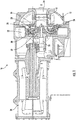
FIG. 1 is a cross-sectional view of a centrifugal compressor; -
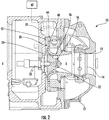
FIG. 2 is a cross-sectional view of a portion of a centrifugal compressor; -
FIG. 3 is a perspective view of a wall of a diffuser section of a compressor; -
FIG. 4A is a front view of another wall of a diffuser section of a compressor; -
FIG. 4B is a cross-sectional view of the wall of the diffuser section ofFIG. 4A compressor; -
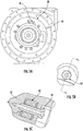
FIG. 5A is a front view of a portion of a diffuser section of a compressor; -
FIG. 5B is a detailed view of section R ofFIG. 5A -
FIG. 5C is a cross-sectional view of section R ofFIG. 5B ; -
FIG. 6 is a detailed cross-sectional view of a diffuser section; and -
FIG. 6A is a cross-sectional view of a coupler of the diffuser section ofFIG. 6 . - A detailed description of one or more embodiments of the disclosed apparatus and method are presented herein by way of exemplification and not limitation with reference to the Figures.
- Referring now to
FIG. 1 , an example of acentrifugal compressor 10 is illustrated. As shown, thecentrifugal compressor 10 includes ahousing 12 having aninlet 14 that directs refrigerant into a rotatingimpeller 16 through a series of adjustableinlet guide vanes 18. Theimpeller 16 is secured to ashaft 20 by any suitable means to alignimpeller 16 along the axis of thecompressor 10. Theimpeller 16 includes ahub 22 supporting a plurality ofblades 24. A plurality ofpassages 26 defined betweenadjacent blades 24 cause the incoming axial flow of a refrigerant fluid to turn in a radial direction and discharge the compressed refrigerant fluid fromrespective passages 26 into anadjacent diffuser section 30. Thediffuser section 30 is generally circumferentially disposed about theimpeller 16 and functions to direct the compressed refrigerant fluid into a toroidal-shaped volute 32, which directs the compressed fluid toward a compressor outlet, or alternatively, toward a second stage of thecompressor 10, depending on the configuration of the compressor. - As best shown in
FIGS. 2 and6 , thediffuser section 30 typically includes afirst wall 40, asecond wall 42, and anopening 44 formed between the first andsecond walls first wall 40 and thesecond wall 42 may be formed from any suitable material including a metal. The opening 44 is arranged in fluid communication with the radial flow discharged from theimpeller 16. As shown, one or both of thefirst wall 40 and thesecond wall 42 has anouter edge 43 located near thevolute 32 and aninner edge 45 positioned adjacent theimpeller 16. An example of awall 50, such as either thefirst wall 40 or thesecond wall 42 is illustrated in more detail inFIG. 3 . Thewall 50 may be disc-like in shape and has a substantially uniform thickness. Further, thesurface 52 of thewall 50 configured to face theopening 44 may have a generally planar configuration. Alternatively, thewall 50 may have a nonuniform thickness and/or thesurface 52 may have a non-planar configuration (seeFIGS. 4A and 4B ). Additionally, although thewall 50 inFIG. 3 is illustrated as being formed from a single piece, as shown inFIGS. 4A and 4B , thewall 50 may be formed from a plurality of pieces positioned adjacent one another. For example, thewall 50 may include afirst piece 54a and asecond piece 54b arranged concentrically with thefirst piece 54a. Although only two pieces are shown, eitherwall pieces 54 including more than two pieces. Where thewall 50 includes a plurality ofpieces 54, thepieces 54 may be coupled together, such as via a fastener, adhesive, or another suitable coupling mechanism, or may be separate. Further, thepieces 54 may, but need not be identical in shape, size, thickness, and contour of thesurface 52. - Referring again to
FIG. 3 , thewall 50 includes a plurality of circumferentially spaced, fixedvanes 56, extending from thesurface 52 toward theopening 44. The plurality ofvanes 56 may be substantially identical, or alternatively, may vary in size, shape, and/or orientation relative to a central axis X of thecompressor 10. As the refrigerant passes through thepassageways 58 defined betweenadjacent vanes 56, the kinetic energy of the refrigerant may be converted to a potential energy or static pressure. However, it should be understood that arrangements where only one of the first andsecond wall vanes 56, or where neither thefirst wall 40 nor thesecond wall 42 hasvanes 56 extending therefrom into theopening 44 are also possible. - At least a portion of the
diffuser section 30, is rotatable about the axis X. More specifically, at least one of thefirst wall 40 and thesecond wall 42, or at least a portion of eitherwall pieces 54 thereof for example, are rotatable about the axis X. Rotation of one ormore walls diffuser section 30 may be driven by another component. For instance, at least apiece 54 of thefirst wall 40 and/or thesecond wall 42 may be coupled to a portion of theimpeller 16, such as thehub 22 or ashroud 23, such that rotation of thewall impeller 16. Where at least one of thewalls impeller 16, the at least onewall impeller 16 will rotate in unison, in the same direction and with the same velocity. Alternatively, thewall impeller 16, such as via a gear train or other coupling mechanism. In that case, thewall impeller 16, it should be understood that thewall piece 54 thereof may be coupled to any rotating component of thecompressor 10, such as theshaft 20 for example. - In another arrangement, rotation of at least one of the
first wall 40 and thesecond wall 42, or at least apiece 54 of eitherwall pieces 54 thereof, may be driven by a motor, actuator, or other power driven component. The motor may be the same motor used to drive rotation of theshaft 20 about axis X, illustrated inFIG. 1 at 34, or alternatively, may be a separate motor, illustrated schematically at 60 inFIG. 2 , located either within or external to thecompressor housing 12. The motor coupled to the rotating portion of thediffuser section 30 may be a variable speed motor such that the rotational speed of thefirst wall 40 orsecond wall 42 coupled thereto may be adjusted, such as in response to one or more operating conditions of thecompressor 10. - In yet another arrangement, at least one of the
first wall 40, thesecond wall 42, or apiece 54 of eitherwall opening 44 of thediffuser section 30. To allow one ormore pieces 54 of thefirst wall 40 or thesecond wall 42 to rotate freely, the freelyrotatable pieces 54 are mounted to an adjacent portion of thecompressor 10, such as thehousing 12,impeller shroud 23,shaft 20, or another component coupled to theshaft 20, via at least onecoupling mechanism 62 that allows for relative rotation there between. InFIGS. 5A-5C , thecoupling mechanism 62 includes a roller assembly. However, anysuitable coupling mechanism 62, such as a bearing for example, may be used. As shown, a plurality ofroller assemblies 62 are positioned at the interface between a wall, such aswall 42 of thediffuser section 30, and an adjacent component, such as a portion of theimpeller 16. In the illustrated arrangement threeroller assemblies 62 are arranged at the interface; however, it should be understood that any number ofroller assemblies 62, such as one, two, or more than three roller assemblies are also possible. As shown, afastener 64 is used to couple eachroller assembly 62 to thewall 42 of thediffuser section 30. Accordingly, theroller assembly 62 is rotatable about the respective axis F defined by the mountingfastener 63, to allow theadjacent wall 42 of thediffuser section 30 to rotate about axis X. - A single wall, either
wall 40 orwall 42, may have apiece 54a that is stationary and asecond piece 54b that is rotatable about the axis X. Further the wall may have a plurality of pieces, each of which is rotatable about the axis X at different speeds. Various configurations may be used to achieve these different rotational speeds. For example, a wall may have apiece 54 that is freely rotatable and anotherpiece 54 that is rotatably driven by a component or motor. Alternatively, or in addition, one of the walls may have apiece 54 driven by a first component or motor, and anotherpiece 54 driven by a second component or motor. - In addition, arrangements where at least a
piece 54 of one wall is rotatable and at least apiece 54 of the other wall of thediffuser section 30 is stationary, or embodiments where at least apiece 54 of each of thefirst wall 40 and thesecond wall 40 are rotatable are possible. Where one ormore pieces 54 of both thefirst wall 40 and thesecond wall 42 are rotatable, at least apiece 54 of one of thewalls piece 54 of the other wall may be driven, at least a piece of bothwalls walls - With reference now to
FIG. 6 , where a piece of one of thewalls more couplers 64 may extend between thefirst wall 40 and thesecond wall 42. By including thecouplers 64, the rotation of the drivenpiece 54 of one wall is transmitted to the freelyrotatable piece 54 of the other wall. Thecoupler 64 may have an airfoil shape (seeFIG. 6A ) to minimize aerodynamic losses within theopening 44 of thediffuser section 30. - A rotating diffuser as illustrated and described herein improves the efficiency of the compressor stage relative to existing compressors having a stationary diffuser, such as by 3-5 %.
- The terminology used herein is for the purpose of describing particular embodiments only and is not intended to be limiting. As used herein, the singular forms "a", "an" and "the" are intended to include the plural forms as well, unless the context clearly indicates otherwise. It will be further understood that the terms "comprises" and/or "comprising," when used in this specification, specify the presence of stated features, integers, steps, operations, elements, and/or components, but do not preclude the presence or addition of one or more other features, integers, steps, operations, element components, and/or groups thereof.
- While the present disclosure has been described with reference to an exemplary embodiment or embodiments, it will be understood by those skilled in the art that various changes may be made and equivalents may be substituted for elements thereof without departing from the scope of the present invention, as defined by the claims. In addition, many modifications may be made to adapt a particular situation or material to the teachings of the present disclosure. Therefore, it is intended that the present invention not be limited to the particular embodiment disclosed for carrying out this present invention, but that the present invention will include all embodiments falling within the scope of the claims.
Claims (14)
Applications Claiming Priority (1)
| Application Number | Priority Date | Filing Date | Title |
|---|---|---|---|
| US201962803945P | 2019-02-11 | 2019-02-11 |
Publications (2)
| Publication Number | Publication Date |
|---|---|
| EP3693613A1 true EP3693613A1 (en) | 2020-08-12 |
| EP3693613B1 EP3693613B1 (en) | 2026-04-15 |
Family
ID=69570551
Family Applications (1)
| Application Number | Title | Priority Date | Filing Date |
|---|---|---|---|
| EP20156417.6A Active EP3693613B1 (en) | 2019-02-11 | 2020-02-10 | Rotating diffuser in centrifugal compressor |
Country Status (3)
| Country | Link |
|---|---|
| US (1) | US11346366B2 (en) |
| EP (1) | EP3693613B1 (en) |
| CN (1) | CN111550447B (en) |
Families Citing this family (1)
| Publication number | Priority date | Publication date | Assignee | Title |
|---|---|---|---|---|
| US11346366B2 (en) * | 2019-02-11 | 2022-05-31 | Carrier Corporation | Rotating diffuser in centrifugal compressor |
Citations (5)
| Publication number | Priority date | Publication date | Assignee | Title |
|---|---|---|---|---|
| US3868196A (en) * | 1974-03-29 | 1975-02-25 | Gen Electric | Centrifugal compressor with rotating vaneless diffuser powered by leakage flow |
| US3941501A (en) * | 1974-11-18 | 1976-03-02 | Avco Corporation | Diffuser including a rotary stage |
| US5899661A (en) * | 1997-08-06 | 1999-05-04 | Carrier Corporation | Axial restraint system for variable pipe diffuser |
| CN201330717Y (en) * | 2009-01-05 | 2009-10-21 | 珠海格力电器股份有限公司 | Adjustable centrifugal compressor |
| EP3521635A1 (en) * | 2018-02-02 | 2019-08-07 | Carrier Corporation | Silencer for a centrifugal compressor assembly |
Family Cites Families (27)
| Publication number | Priority date | Publication date | Assignee | Title |
|---|---|---|---|---|
| US2321276A (en) * | 1939-09-20 | 1943-06-08 | Bolt Vaughn S De | Turbocompressor |
| US2344366A (en) * | 1941-03-21 | 1944-03-14 | Lockheed Aircraft Corp | Counterrotating supercharger |
| FR1124752A (en) * | 1955-04-19 | 1956-10-17 | Improvements to turbo-machines | |
| US3044685A (en) * | 1959-02-13 | 1962-07-17 | Nicholas P Lapiken | Air compressor |
| US3150650A (en) * | 1961-09-29 | 1964-09-29 | Caterpillar Tractor Co | Variable area diffuser for compressor |
| US3197124A (en) * | 1962-04-03 | 1965-07-27 | Sallou Jean | Centrifugal pump impellers |
| US3378229A (en) * | 1965-07-16 | 1968-04-16 | Gen Electric | Radial flow turbine |
| US3460748A (en) * | 1967-11-01 | 1969-08-12 | Gen Electric | Radial flow machine |
| US3521635A (en) | 1968-05-22 | 1970-07-28 | Wilbur R Koehn | Flowmeter de-aerator for parenteral fluid administration set |
| DE2436458A1 (en) * | 1973-08-17 | 1975-02-20 | Int Harvester Co | CENTRIFUGAL COMPRESSORS |
| US4455121A (en) * | 1982-11-01 | 1984-06-19 | Avco Corporation | Rotating turbine stator |
| SU1339302A1 (en) * | 1986-04-28 | 1987-09-23 | И. К. Попов | Centrifugal blower |
| CN1022435C (en) * | 1989-06-26 | 1993-10-13 | 川波春平 | Oppositely-arranged double-rotor centrifugal fluid-charger |
| DE4133736C2 (en) * | 1991-10-11 | 1993-10-07 | Daimler Benz Ag | Exhaust gas turbocharger for an internal combustion engine |
| JPH116497A (en) * | 1997-06-18 | 1999-01-12 | Kawasaki Heavy Ind Ltd | Centrifugal multi-blade blower |
| US6099168A (en) | 1997-08-06 | 2000-08-08 | Carrier Corporation | Composite roller bearing for variable pipe diffuser |
| US5988977A (en) | 1997-08-06 | 1999-11-23 | Carrier Corporation | Backlash adjustment mechanism for variable pipe diffuser |
| US6015259A (en) | 1997-08-06 | 2000-01-18 | Carrier Corporation | Support mechanism of inner ring for variable pipe diffuser |
| US5895204A (en) | 1997-08-06 | 1999-04-20 | Carrier Corporation | Drive positioning mechanism for a variable pipe diffuser |
| FR2794492B1 (en) * | 1999-06-03 | 2001-08-03 | Onera (Off Nat Aerospatiale) | IMPROVEMENTS IN RADIAL TURBOMACHINES |
| GB0102028D0 (en) * | 2001-01-26 | 2001-03-14 | Academy Projects Ltd | An engine and bearings therefor |
| US6554567B2 (en) | 2001-09-21 | 2003-04-29 | Carrier Corporation | Compliant mechanical stop for limiting split ring diffuser travel |
| US6506011B1 (en) | 2001-09-21 | 2003-01-14 | Carrier Corporation | Method for limiting split ring diffuser travel |
| US9097258B2 (en) * | 2009-06-25 | 2015-08-04 | General Electric Company | Supersonic compressor comprising radial flow path |
| CN101922459B (en) * | 2010-07-28 | 2012-06-13 | 康跃科技股份有限公司 | Electric composite multi-stage centrifugal compressor device |
| DE102015203171B4 (en) * | 2015-02-23 | 2025-03-20 | Ford Global Technologies, Llc | Exhaust gas turbocharged internal combustion engine comprising a radial compressor with a guide device arranged in the diffuser and method for operating such an internal combustion engine |
| US11346366B2 (en) * | 2019-02-11 | 2022-05-31 | Carrier Corporation | Rotating diffuser in centrifugal compressor |
-
2020
- 2020-01-31 US US16/778,729 patent/US11346366B2/en active Active
- 2020-02-10 CN CN202010084553.5A patent/CN111550447B/en active Active
- 2020-02-10 EP EP20156417.6A patent/EP3693613B1/en active Active
Patent Citations (5)
| Publication number | Priority date | Publication date | Assignee | Title |
|---|---|---|---|---|
| US3868196A (en) * | 1974-03-29 | 1975-02-25 | Gen Electric | Centrifugal compressor with rotating vaneless diffuser powered by leakage flow |
| US3941501A (en) * | 1974-11-18 | 1976-03-02 | Avco Corporation | Diffuser including a rotary stage |
| US5899661A (en) * | 1997-08-06 | 1999-05-04 | Carrier Corporation | Axial restraint system for variable pipe diffuser |
| CN201330717Y (en) * | 2009-01-05 | 2009-10-21 | 珠海格力电器股份有限公司 | Adjustable centrifugal compressor |
| EP3521635A1 (en) * | 2018-02-02 | 2019-08-07 | Carrier Corporation | Silencer for a centrifugal compressor assembly |
Also Published As
| Publication number | Publication date |
|---|---|
| EP3693613B1 (en) | 2026-04-15 |
| US20200256352A1 (en) | 2020-08-13 |
| CN111550447B (en) | 2024-10-29 |
| US11346366B2 (en) | 2022-05-31 |
| CN111550447A (en) | 2020-08-18 |
Similar Documents
| Publication | Publication Date | Title |
|---|---|---|
| EP3540236B1 (en) | Refrigeration system mixed-flow compressor | |
| US8100630B2 (en) | Fluid flow machine with multi-flow rotor arrangement | |
| EP2447538B1 (en) | System and method of assembling a supersonic compressor system including a supersonic compressor rotor and a compressor assembly | |
| EP1792054B1 (en) | Radial variable area diffuser for a radial compressor | |
| US11592034B2 (en) | Vaneless supersonic diffuser for compressor | |
| WO2020242788A1 (en) | Mixed-flow compressor configuration for a refrigeration system | |
| US12044240B2 (en) | Refrigeration system mixed-flow compressor | |
| EP3693613B1 (en) | Rotating diffuser in centrifugal compressor | |
| EP3705698A1 (en) | Turbine and turbocharger | |
| US11965514B2 (en) | Axial and downstream compressor assembly | |
| JP6065509B2 (en) | Centrifugal compressor | |
| US11499569B2 (en) | Mixed-flow compressor with counter-rotating diffuser | |
| EP0984136A1 (en) | Double-sided centrifugal-centripetral turbine | |
| EP4261415A1 (en) | Two stage mixed-flow compressor | |
| JP3380897B2 (en) | Compressor | |
| KR100405984B1 (en) | Diffuser mounting structure of Turbo compressor | |
| JP2000291593A (en) | Compressor | |
| KR101883480B1 (en) | Centrifugal compressor | |
| KR20020084613A (en) | Centrifugal compressor | |
| JP2003293994A (en) | Centrifugal compressor and method of operating centrifugal compressor | |
| KR20050006102A (en) | centrifugal impeller installing with a fluid passage guide | |
| JP2014074391A (en) | Centrifugal compressor |
Legal Events
| Date | Code | Title | Description |
|---|---|---|---|
| PUAI | Public reference made under article 153(3) epc to a published international application that has entered the european phase |
Free format text: ORIGINAL CODE: 0009012 |
|
| STAA | Information on the status of an ep patent application or granted ep patent |
Free format text: STATUS: THE APPLICATION HAS BEEN PUBLISHED |
|
| AK | Designated contracting states |
Kind code of ref document: A1 Designated state(s): AL AT BE BG CH CY CZ DE DK EE ES FI FR GB GR HR HU IE IS IT LI LT LU LV MC MK MT NL NO PL PT RO RS SE SI SK SM TR |
|
| AX | Request for extension of the european patent |
Extension state: BA ME |
|
| STAA | Information on the status of an ep patent application or granted ep patent |
Free format text: STATUS: REQUEST FOR EXAMINATION WAS MADE |
|
| 17P | Request for examination filed |
Effective date: 20210212 |
|
| RBV | Designated contracting states (corrected) |
Designated state(s): AL AT BE BG CH CY CZ DE DK EE ES FI FR GB GR HR HU IE IS IT LI LT LU LV MC MK MT NL NO PL PT RO RS SE SI SK SM TR |
|
| STAA | Information on the status of an ep patent application or granted ep patent |
Free format text: STATUS: EXAMINATION IS IN PROGRESS |
|
| 17Q | First examination report despatched |
Effective date: 20220510 |
|
| GRAP | Despatch of communication of intention to grant a patent |
Free format text: ORIGINAL CODE: EPIDOSNIGR1 |
|
| STAA | Information on the status of an ep patent application or granted ep patent |
Free format text: STATUS: GRANT OF PATENT IS INTENDED |
|
| INTG | Intention to grant announced |
Effective date: 20251110 |
|
| GRAS | Grant fee paid |
Free format text: ORIGINAL CODE: EPIDOSNIGR3 |
|
| GRAA | (expected) grant |
Free format text: ORIGINAL CODE: 0009210 |
|
| STAA | Information on the status of an ep patent application or granted ep patent |
Free format text: STATUS: THE PATENT HAS BEEN GRANTED |
|
| AK | Designated contracting states |
Kind code of ref document: B1 Designated state(s): AL AT BE BG CH CY CZ DE DK EE ES FI FR GB GR HR HU IE IS IT LI LT LU LV MC MK MT NL NO PL PT RO RS SE SI SK SM TR |
|
| REG | Reference to a national code |
Ref country code: CH Ref legal event code: F10 Free format text: ST27 STATUS EVENT CODE: U-0-0-F10-F00 (AS PROVIDED BY THE NATIONAL OFFICE) Effective date: 20260415 |
|
| REG | Reference to a national code |
Ref country code: DE Ref legal event code: R096 Ref document number: 602020070293 Country of ref document: DE |