EP3693591B1 - Abwärmenutzung - Google Patents
Abwärmenutzung Download PDFInfo
- Publication number
- EP3693591B1 EP3693591B1 EP20155263.5A EP20155263A EP3693591B1 EP 3693591 B1 EP3693591 B1 EP 3693591B1 EP 20155263 A EP20155263 A EP 20155263A EP 3693591 B1 EP3693591 B1 EP 3693591B1
- Authority
- EP
- European Patent Office
- Prior art keywords
- working medium
- drive unit
- temperature side
- heat exchange
- thermoelectric generator
- Prior art date
- Legal status (The legal status is an assumption and is not a legal conclusion. Google has not performed a legal analysis and makes no representation as to the accuracy of the status listed.)
- Active
Links
Images




Classifications
-
- F—MECHANICAL ENGINEERING; LIGHTING; HEATING; WEAPONS; BLASTING
- F01—MACHINES OR ENGINES IN GENERAL; ENGINE PLANTS IN GENERAL; STEAM ENGINES
- F01N—GAS-FLOW SILENCERS OR EXHAUST APPARATUS FOR MACHINES OR ENGINES IN GENERAL; GAS-FLOW SILENCERS OR EXHAUST APPARATUS FOR INTERNAL-COMBUSTION ENGINES
- F01N5/00—Exhaust or silencing apparatus combined or associated with devices profiting by exhaust energy
- F01N5/02—Exhaust or silencing apparatus combined or associated with devices profiting by exhaust energy the devices using heat
- F01N5/025—Exhaust or silencing apparatus combined or associated with devices profiting by exhaust energy the devices using heat the device being thermoelectric generators
-
- F—MECHANICAL ENGINEERING; LIGHTING; HEATING; WEAPONS; BLASTING
- F02—COMBUSTION ENGINES; HOT-GAS OR COMBUSTION-PRODUCT ENGINE PLANTS
- F02G—HOT GAS OR COMBUSTION-PRODUCT POSITIVE-DISPLACEMENT ENGINE PLANTS; USE OF WASTE HEAT OF COMBUSTION ENGINES; NOT OTHERWISE PROVIDED FOR
- F02G5/00—Profiting from waste heat of combustion engines, not otherwise provided for
- F02G5/02—Profiting from waste heat of exhaust gases
-
- F—MECHANICAL ENGINEERING; LIGHTING; HEATING; WEAPONS; BLASTING
- F01—MACHINES OR ENGINES IN GENERAL; ENGINE PLANTS IN GENERAL; STEAM ENGINES
- F01K—STEAM ENGINE PLANTS; STEAM ACCUMULATORS; ENGINE PLANTS NOT OTHERWISE PROVIDED FOR; ENGINES USING SPECIAL WORKING FLUIDS OR CYCLES
- F01K23/00—Plants characterised by more than one engine delivering power external to the plant, the engines being driven by different fluids
- F01K23/02—Plants characterised by more than one engine delivering power external to the plant, the engines being driven by different fluids the engine cycles being thermally coupled
-
- F—MECHANICAL ENGINEERING; LIGHTING; HEATING; WEAPONS; BLASTING
- F01—MACHINES OR ENGINES IN GENERAL; ENGINE PLANTS IN GENERAL; STEAM ENGINES
- F01K—STEAM ENGINE PLANTS; STEAM ACCUMULATORS; ENGINE PLANTS NOT OTHERWISE PROVIDED FOR; ENGINES USING SPECIAL WORKING FLUIDS OR CYCLES
- F01K23/00—Plants characterised by more than one engine delivering power external to the plant, the engines being driven by different fluids
- F01K23/02—Plants characterised by more than one engine delivering power external to the plant, the engines being driven by different fluids the engine cycles being thermally coupled
- F01K23/06—Plants characterised by more than one engine delivering power external to the plant, the engines being driven by different fluids the engine cycles being thermally coupled combustion heat from one cycle heating the fluid in another cycle
- F01K23/065—Plants characterised by more than one engine delivering power external to the plant, the engines being driven by different fluids the engine cycles being thermally coupled combustion heat from one cycle heating the fluid in another cycle the combustion taking place in an internal combustion piston engine, e.g. a diesel engine
-
- F—MECHANICAL ENGINEERING; LIGHTING; HEATING; WEAPONS; BLASTING
- F01—MACHINES OR ENGINES IN GENERAL; ENGINE PLANTS IN GENERAL; STEAM ENGINES
- F01K—STEAM ENGINE PLANTS; STEAM ACCUMULATORS; ENGINE PLANTS NOT OTHERWISE PROVIDED FOR; ENGINES USING SPECIAL WORKING FLUIDS OR CYCLES
- F01K23/00—Plants characterised by more than one engine delivering power external to the plant, the engines being driven by different fluids
- F01K23/02—Plants characterised by more than one engine delivering power external to the plant, the engines being driven by different fluids the engine cycles being thermally coupled
- F01K23/06—Plants characterised by more than one engine delivering power external to the plant, the engines being driven by different fluids the engine cycles being thermally coupled combustion heat from one cycle heating the fluid in another cycle
- F01K23/10—Plants characterised by more than one engine delivering power external to the plant, the engines being driven by different fluids the engine cycles being thermally coupled combustion heat from one cycle heating the fluid in another cycle with exhaust fluid of one cycle heating the fluid in another cycle
-
- F—MECHANICAL ENGINEERING; LIGHTING; HEATING; WEAPONS; BLASTING
- F01—MACHINES OR ENGINES IN GENERAL; ENGINE PLANTS IN GENERAL; STEAM ENGINES
- F01N—GAS-FLOW SILENCERS OR EXHAUST APPARATUS FOR MACHINES OR ENGINES IN GENERAL; GAS-FLOW SILENCERS OR EXHAUST APPARATUS FOR INTERNAL-COMBUSTION ENGINES
- F01N5/00—Exhaust or silencing apparatus combined or associated with devices profiting by exhaust energy
-
- F—MECHANICAL ENGINEERING; LIGHTING; HEATING; WEAPONS; BLASTING
- F01—MACHINES OR ENGINES IN GENERAL; ENGINE PLANTS IN GENERAL; STEAM ENGINES
- F01N—GAS-FLOW SILENCERS OR EXHAUST APPARATUS FOR MACHINES OR ENGINES IN GENERAL; GAS-FLOW SILENCERS OR EXHAUST APPARATUS FOR INTERNAL-COMBUSTION ENGINES
- F01N5/00—Exhaust or silencing apparatus combined or associated with devices profiting by exhaust energy
- F01N5/02—Exhaust or silencing apparatus combined or associated with devices profiting by exhaust energy the devices using heat
-
- F—MECHANICAL ENGINEERING; LIGHTING; HEATING; WEAPONS; BLASTING
- F01—MACHINES OR ENGINES IN GENERAL; ENGINE PLANTS IN GENERAL; STEAM ENGINES
- F01P—COOLING OF MACHINES OR ENGINES IN GENERAL; COOLING OF INTERNAL-COMBUSTION ENGINES
- F01P3/00—Liquid cooling
- F01P3/20—Cooling circuits not specific to a single part of engine or machine
-
- H—ELECTRICITY
- H10—SEMICONDUCTOR DEVICES; ELECTRIC SOLID-STATE DEVICES NOT OTHERWISE PROVIDED FOR
- H10N—ELECTRIC SOLID-STATE DEVICES NOT OTHERWISE PROVIDED FOR
- H10N10/00—Thermoelectric devices comprising a junction of dissimilar materials, i.e. devices exhibiting Seebeck or Peltier effects
- H10N10/10—Thermoelectric devices comprising a junction of dissimilar materials, i.e. devices exhibiting Seebeck or Peltier effects operating with only the Peltier or Seebeck effects
- H10N10/13—Thermoelectric devices comprising a junction of dissimilar materials, i.e. devices exhibiting Seebeck or Peltier effects operating with only the Peltier or Seebeck effects characterised by the heat-exchanging means at the junction
-
- F—MECHANICAL ENGINEERING; LIGHTING; HEATING; WEAPONS; BLASTING
- F01—MACHINES OR ENGINES IN GENERAL; ENGINE PLANTS IN GENERAL; STEAM ENGINES
- F01K—STEAM ENGINE PLANTS; STEAM ACCUMULATORS; ENGINE PLANTS NOT OTHERWISE PROVIDED FOR; ENGINES USING SPECIAL WORKING FLUIDS OR CYCLES
- F01K9/00—Plants characterised by condensers arranged or modified to co-operate with the engines
- F01K9/003—Plants characterised by condensers arranged or modified to co-operate with the engines condenser cooling circuits
-
- F—MECHANICAL ENGINEERING; LIGHTING; HEATING; WEAPONS; BLASTING
- F01—MACHINES OR ENGINES IN GENERAL; ENGINE PLANTS IN GENERAL; STEAM ENGINES
- F01P—COOLING OF MACHINES OR ENGINES IN GENERAL; COOLING OF INTERNAL-COMBUSTION ENGINES
- F01P3/00—Liquid cooling
- F01P2003/001—Cooling liquid
-
- Y—GENERAL TAGGING OF NEW TECHNOLOGICAL DEVELOPMENTS; GENERAL TAGGING OF CROSS-SECTIONAL TECHNOLOGIES SPANNING OVER SEVERAL SECTIONS OF THE IPC; TECHNICAL SUBJECTS COVERED BY FORMER USPC CROSS-REFERENCE ART COLLECTIONS [XRACs] AND DIGESTS
- Y02—TECHNOLOGIES OR APPLICATIONS FOR MITIGATION OR ADAPTATION AGAINST CLIMATE CHANGE
- Y02T—CLIMATE CHANGE MITIGATION TECHNOLOGIES RELATED TO TRANSPORTATION
- Y02T10/00—Road transport of goods or passengers
- Y02T10/10—Internal combustion engine [ICE] based vehicles
- Y02T10/12—Improving ICE efficiencies
Definitions
- the invention relates to a drive unit for a motor vehicle and a motor vehicle with such a drive unit.
- thermoelectric generator it is known to use a steam circuit process device or a thermoelectric generator to utilize waste heat from an internal combustion engine, it being possible by means of these devices to use in particular waste heat from the exhaust gas of the internal combustion engine (cf. DE 10 2014 015 457 A1 or DE 10 2014 001 819 A1 ).
- the DE 10 2010 048 887 A1 discloses in this regard a combined use of a steam cycle process device and a thermoelectric generator for utilizing waste heat from an internal combustion engine.
- the thermoelectric generator is thermally conductively connected to the cyclic process device via a cooling fluid line. This makes it possible to partially use waste heat from the steam cycle device in the thermoelectric generator by converting it into electrical energy.
- the DE 10 2010 048 888 A1 discloses a drive unit in which both the high-temperature side and the low-temperature side of a thermoelectric generator are integrated into a cyclic process device and the working medium of the cyclic process device thus flows through them.
- the DE 10 2010 038 314 A1 discloses a drive unit similar thereto, but in which the evaporator of the cyclic process device is combined with a thermoelectric generator, wherein the working medium of the cyclic process device flows through the low-temperature side of the thermoelectric generator.
- the object of the invention was to enable better use of waste heat from an internal combustion engine of a motor vehicle.
- a drive unit for a motor vehicle and a motor vehicle with such a drive unit having an internal combustion engine on the one hand, which includes an internal combustion engine and an exhaust line via which exhaust gas from the internal combustion engine can be discharged.
- the drive unit has a cyclic process device that is set up to convert thermal energy of the exhaust gas into mechanical work in a (clockwise) thermodynamic cycle process, with a working medium flowing through a first heat exchange device with regard to its flow direction, in which a (direct or indirect) heat transfer from the Exhaust takes place on the working medium, whereby the temperature and / or the pressure of the working medium is increased.
- the working medium then flows through an expansion device, in which the working medium expands and the mechanical work is generated in the process.
- the working medium then flows through a second heat exchange device, in which there is a (direct or indirect) heat transfer from the working medium to a cooling medium.
- a drive unit also includes a thermoelectric generator (TEG) which is set up to convert thermal energy of the exhaust gas into electrical energy and which provides an electrical voltage when there is a temperature difference between its high-temperature side and its low-temperature side.
- TEG thermoelectric generator
- the TEG comprises, in a known manner, at least one thermocouple, usually a large number of thermocouples, in which, according to the thermoelectric effect (also called “Seebeck effect"), in a circuit formed from two different electrical conductors, at a temperature difference an electrical voltage is applied between the contact points of these electrical conductors.
- the electrical conductors can preferably be formed from metals and in particular from semiconductors. Such TEG enable a direct conversion of thermal energy into electrical energy.
- such a TEG comprises a first heat exchanger, which is thermally conductively connected to one end of the electrical conductor, hereinafter referred to as the high-temperature side of the TEG, by means of which a relatively high temperature of these ends of the electrical conductors is set, as well as a second heat exchanger connected to the other end of the electrical conductors, hereinafter referred to as the low-temperature side of the TEG, in which a relatively low temperature for the associated ends of the electrical conductors is achieved through targeted heat dissipation or cooling is set.
- the TEG is integrated into the cyclic process device in such a way that the working medium is or can also be routed via it.
- a thermal coupling of the cyclic process device and the TEG can be realized in a particularly advantageous manner, which has a positive effect with regard to the overall efficiency of the use of waste heat and/or with regard to the constructive and spatial combination of these two devices.
- the working medium can be routed via the high-temperature side of the TEG.
- the low-temperature side of the TEG is cooled by means of a coolant that differs from the working medium, in particular by means of the coolant also used for cooling in the second heat exchange device of the cyclic process device and/or by means of ambient air that is supplied in a targeted manner.
- a drive unit according to the invention is based in particular on using a still relatively high temperature of the working medium to realize the greatest possible temperature difference between the high-temperature side and the low-temperature side of the TEG.
- the TEG or the high-temperature side thereof with respect to the flow direction of the working medium can preferably be arranged either downstream of the expansion device and upstream of the second heat exchange device or downstream of the first heat exchange device and upstream of the expansion device or integrated into the circuit for the working medium of the cyclic process device.
- the first of these alternative arrangements is based on the assumption that the temperature of the working medium is still sufficiently high after the expansion device to generate an advantageously high temperature difference between the high-temperature side and the low-temperature side for the TEG.
- cooling and in particular condensing of the working medium in the second Heat exchange device of the cyclic process device can be practically limited.
- the second of these alternative arrangements of the TEG or of its high-temperature side can be provided in particular if the power rating of the expansion device is not based on a maximum heat flow to be expected during operation of the drive unit, which can be transferred to the working medium in the first heat exchange device of the cyclic process device but on the basis of a comparatively lower, in particular average, heat flow, as a result of which an overall better efficiency of the cyclic process device can be achieved over all operating states of the drive unit.
- the TEG can then also be used in particular to use the excess heat output by means of the TEG when the drive unit is operated with a heat flow that is greater than that for which the expansion device is designed, so that, for example, the output of the Cyclic process device can be dispensed with to avoid overloading the expansion device.
- Another advantage of this second arrangement of the TEG can be the still relatively high temperature of the working medium when flowing over the high-temperature side of the TEG and thus a correspondingly high temperature difference between this high-temperature side and the low-temperature side. This has an advantageous effect with regard to the electrical power provided by the TEG.
- the exhaust gas whose waste heat is to be used can in particular be an exhaust gas which is intended at least partially, preferably completely, to be discharged into the environment.
- the cycle process device is a steam cycle process device which is set up in particular to carry out a and in particular a Clausius-Rankine cycle process, and in which the working medium in the liquid state is pressure-increased by means of a pump, then in the first Heat exchange device is vaporized and preferably overheated and is condensed in the second heat exchange device.
- the cooling medium which is used at least in the second heat exchange device of the cyclic process device for dissipating heat energy, can be a coolant that circulates in a cooling system of the internal combustion engine and in particular in an engine cooling circuit of this cooling system that includes at least one cooling duct of the internal combustion engine.
- This makes it possible, among other things, to easily dissipate the waste heat from the cycle process, which can represent a large part (e.g. approx. 85%) of the heat energy supplied, to the ambient air via a coolant liquid cooler of the cooling system.
- ambient air is used to cool the working medium by means of the second heat exchange device.
- the TEG can be integrated into the cyclic process device in such a way that the cooling medium, which is used for heat dissipation in the second heat exchange device of the cyclic process device, is/can also be routed via the low-temperature side of the TEG in order to avoid this to cool.
- cooling of the low-temperature side of the thermoelectric generator can also be provided by means of a coolant that differs from the cooling medium, in particular a gas, then particularly preferably by means of ambient air that is supplied in a targeted manner.
- the first heat exchange device and the TEG are designed to be integrated in a heat exchange unit.
- the drive unit can be configured as compactly as possible.
- a working medium channel provided for the flow of the working medium of the first heat exchange device is arranged between an exhaust gas channel provided for the flow of the exhaust gas on the one hand and the high-temperature side of the TEG on the other hand.
- the working medium flowing into the working medium channel can thus serve as a heat absorber for the high-temperature side of the TEG, as a result of which it can be protected from temporary temperature peaks in the exhaust gas, which can be detrimental to its durability.
- Such a heat exchange unit can be designed in a structurally advantageous manner in that the working medium channel surrounds the exhaust gas channel on the peripheral side and the high-temperature side of the thermoelectric generator surrounds or delimits the working medium channel on the peripheral side. Provision can then also preferably be made for the low-temperature side and in particular a cooling channel thereof, which is provided for a coolant to flow through, to surround the high-temperature side of the TEG on the peripheral side.
- a motor vehicle according to the invention can in particular be a wheel-based and non-rail-bound motor vehicle, preferably a car or a truck. At least the internal combustion engine of the drive unit of the motor vehicle according to the invention can preferably be provided for the direct or indirect provision of the driving power for the motor vehicle.
- the 1 shows a motor vehicle (according to the invention) with a drive unit according to the invention.
- This drive unit 1 can, for example, according to one of the 2 , 3 and 5 illustrated embodiments may be formed.
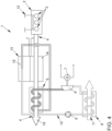
- the drive unit according to the 4 on the other hand, no longer corresponds to the embodiment defined in the patent claims.
- the in the Figures 2 to 5 Drive units 1 shown each comprise an internal combustion engine with an internal combustion engine 2, which is designed, for example, as a diesel or Otto engine.
- an internal combustion engine 2 which is designed, for example, as a diesel or Otto engine.
- one or more combustion chambers 3 are formed, in which, during operation of the internal combustion engine 2, fresh gas (air) with fuel is burned.
- the fresh gas is fed to the internal combustion engine 2 via a fresh gas line, not shown.
- Exhaust gas produced during the combustion of the fresh gas with the fuel is discharged from the internal combustion engine 2 via an exhaust line 4 and discharged into the environment.
- the exhaust gas flows through a first heat exchange device 5 of a cycle device, which is specifically designed as a steam cycle device.
- the exhaust gas and the working medium 10 of the cyclic process device flow through the first heat exchange device 5 , heat being transferred from the exhaust gas to the working medium.
- This heat transfer leads to the working medium 10 evaporating and overheating in the first heat exchange device 5 designed as an evaporator a generator 7 can be used.
- a second heat exchange device 8 of the cyclic process device which serves as a condenser, the working medium 10 is then cooled and converted back into the liquid phase.
- a pump 9 of the cycle device re-supplies the liquid working fluid 10 to the first heat exchange device (evaporator) 5 to close the circuit of the working fluid 10 in the cycle device.
- the second heat exchange device (condenser) 8 is also (separated from one another) flowed through by a cooling medium 11, for example a cooling liquid which flows in an engine cooling circuit of a cooling system 12 of the internal combustion engine, with the cycle process being carried out by means of the cycle process device Heat transfer from the working medium 10 to the cooling medium 11 takes place.
- a cooling medium 11 for example a cooling liquid which flows in an engine cooling circuit of a cooling system 12 of the internal combustion engine
- the drive units according to Figures 2 to 5 each also include a thermoelectric generator (TEG) 13, which is integrated into the cyclic process device in such a way that the working medium 10 is also guided over it. This is done in order to influence or generate and maintain a temperature difference between these sides of the thermoelectric generator 13 by means of a heat transfer between the working medium 10 and either a high-temperature side 14 or a low-temperature side 15 of the thermoelectric generator 13 .
- the TEG 13 can be used to generate useful electrical power that can be fed, for example, into an on-board network of the drive unit or into an on-board network of a motor vehicle that includes the drive unit.
- the specific types of integration of the TEG 13 in the respective cyclic process device differ in the drive units 1 according to the Figures 2 to 5 .
- the working medium 10 is guided over the high-temperature side 14 of the TEG 13 .
- the TEG 13 or the high-temperature side 14 thereof is arranged downstream of the expansion device 6 and upstream of the second heat exchange device (condenser) 8 with respect to the intended flow direction of the working medium 10 in the cycle process device.
- this arrangement has the advantage that the TEG 13 pre-cools the working medium 10 that is then to be fed to the second heat exchange device (capacitor) 8, thereby causing condensation of the working medium 10 in the second heat exchange device (Capacitor) 8 supported.
- the cooling medium used to cool the working medium 10 in the second heat exchange device (condenser) 8 is a cooling liquid which flows in an engine cooling circuit of a cooling system 12 of the internal combustion engine and which as a result regularly has a relatively high fluid temperature , which can be associated with a relatively low cooling capacity of this second heat exchange device (condenser) 8 .
- the coolant 16, which flows through and/or around the low-temperature side 15 of the TEG 13, can preferably be a coolant 16 that differs from the coolant of the cooling system 12, for example ambient air that is supplied specifically for cooling the low-temperature side 15 of the TEG 13, act.
- this coolant 16 can advantageously have a relatively low fluid temperature compared to the cooling liquid of cooling system 12, which results in the greatest possible temperature difference between the high-temperature side 14 and the low-temperature side 15 of the TEG 13 and thus in the greatest possible temperature that can be generated by the TEG 13 electrical power can lead.
- the one in the 3 illustrated drive unit 1 differs from that according to 2 only in the arrangement of the TEG 13.
- the high-temperature side 14 of the TEG 13, through which the working medium 10 of the cyclic process device flows, is arranged downstream of the first heat exchange device (evaporator) 5 and upstream of the expansion device 6 with respect to the direction of flow of the working medium 10.
- this arrangement has the advantage that the working medium 10 guided through the high-temperature side 14 of the TEG 13 has a relatively high temperature, which leads to a correspondingly high temperature difference between the High-temperature side 14 and the low-temperature side 15 of the TEG 13 and consequently to a correspondingly high useful output that can be generated by means of the TEG 13 leads.
- this arrangement of the TEG 13 can ensure that temporarily comparatively high temperatures of the working medium 10, which result from a correspondingly high exhaust gas heat supply, which results, for example, from operating the internal combustion engine 2 at high and in particular maximum loads and speeds, are reduced by means of the TEG 13 be before the working medium 10 reaches the expansion device 6.
- This can be particularly advantageous if the expansion device 6 is designed with regard to the highest possible degree of efficiency with a rather average supply of exhaust gas heat.
- Such a design of the expansion device 6 or the entire cyclic process device can be advantageous because internal combustion engines that are intended to drive motor vehicles are usually used most of the time in partial load operation, so that it can make sense to design the cyclic process device in such a way that it an exhaust heat supply provided in such a partial load operation achieves the highest possible efficiency.
- this drive unit 1 it may be useful to temporarily at least partially prevent a flow through the high-pressure side 14 of the TEG 13 by at least partially guiding the working medium 10 to the TEG 13 via a bypass 17 .
- This can be adjusted using a corresponding control valve 18 .
- the amount of heat energy in the working medium 10 that is used in the TEG 13 to generate useful electrical power and that is therefore no longer available for use in the expansion device 6 can be controlled as required.
- the coolant 16, which flows through and/or around the low-temperature side 15 of the TEG 13, can in turn preferably be a coolant 16 that differs from the coolant of the cooling system 12, for example ambient air that is supplied in a targeted manner.
- This coolant 16 can advantageously have a relatively low fluid temperature compared to the coolant of the cooling system 12, which leads to the greatest possible temperature difference between the high-temperature side 14 and the low-temperature side 15 and thus to the greatest possible electrical power that can be generated by the TEG 13 can.
- the working medium 10 of the cyclic process device is guided over the low-temperature side 15 of the TEG 13 .
- the exhaust gas 19 flows directly through and/or around the high-temperature side 14 of the TEG 13 . This takes place before the exhaust gas 19 enters the first heat exchange device (evaporator) 5 flows through the cycle device.
- this leads to a relatively high temperature on the high-temperature side 14 of the TEG 13 and thus to a correspondingly high temperature difference between the high-temperature side 14 and the low-temperature side 15.
- the useful power that can be achieved by means of the TEG 13 can therefore be correspondingly high.
- thermal energy that is transferred to the working medium 10 in the low-temperature side 15 of the TEG 13 can advantageously be used to preheat the working medium 10 before it enters the first heat exchange device (evaporator) 5 of the cycle device.
- the TEG 13 or its low-temperature side 15 is integrated in an arrangement downstream of the second heat exchange device (condenser) 8 and upstream of the first heat exchange device (evaporator) 5 in the circuit of the cyclic process device.
- an integral formation of the first heat exchange device (evaporator) 5 of the cyclic process device and the TEG 13 is provided in a heat exchange unit 20, in which a working medium channel 21, intended for the flow of the working medium 10, of the first heat exchange device (evaporator) 5 between a flow of the exhaust gas 19 provided exhaust gas duct 22 on the one hand and the high-temperature side 14 of the TEG 13 on the other hand.
- a working medium channel 21 intended for the flow of the working medium 10, of the first heat exchange device (evaporator) 5 between a flow of the exhaust gas 19 provided exhaust gas duct 22 on the one hand and the high-temperature side 14 of the TEG 13 on the other hand.
- the high-temperature side 14 is in turn circumferentially surrounded by the low-temperature side 15 of the TEG 13, with a plurality of thermocouples 23 connected in series to form a thermal chain structurally connecting the high-temperature side 14 and the low-temperature side 15 of the TEG 13.
- the low-temperature side 15 of the TEG can optionally include a coolant channel 24 , which can also be ring-shaped and through which a coolant 16 for cooling the low-temperature side 15 of the TEG 13 can be guided.
- coolant 16 which in the drive unit 1 according to the figure 5 flows through and/or around the low-temperature side 15 of the TEG 13, it can in turn preferably be a coolant 16 that differs from the coolant of the cooling system 12, for example ambient air that is supplied in a targeted manner.
Landscapes
- Engineering & Computer Science (AREA)
- Chemical & Material Sciences (AREA)
- Combustion & Propulsion (AREA)
- Mechanical Engineering (AREA)
- General Engineering & Computer Science (AREA)
- Engine Equipment That Uses Special Cycles (AREA)
- Air-Conditioning For Vehicles (AREA)
Description
- Die Erfindung betrifft eine Antriebseinheit für ein Kraftfahrzeug und ein Kraftfahrzeug mit einer solchen Antriebseinheit.
- Kraftfahrzeuge werden häufig mittels Verbrennungsmotoren angetrieben, in denen Kraftstoffe verbrannt und die dabei freigesetzte Wärmeenergie teilweise in mechanische Arbeit umgewandelt wird. Der Wirkungsgrad von Hubkolben-Verbrennungsmotoren, die für den Antrieb von Kraftfahrzeugen nahezu ausschließlich eingesetzten werden, liegt gemittelt bei ca. einem Drittel der eingesetzten Primärenergie. Demnach stellen zwei Drittel der bei der Verbrennung freigesetzten Wärmeenergie Abwärme dar, die entweder über ein Kühlsystem des Kraftfahrzeugs oder über das von dem Abgasstrang ausgestoßene als Verlustwärme an die Umgebung abgegeben wird.
- Eine Nutzung dieser Abwärme stellt eine Möglichkeit dar, den Gesamtwirkungsgrad einer Antriebseinheit des Kraftfahrzeugs zu steigern und damit den Kraftstoffverbrauch zu senken.
- Bekannt ist, zur Nutzung von Abwärme eines Verbrennungsmotors eine Dampfkreisprozessvorrichtung oder einen thermoelektrischen Generator zu verwenden, wobei mittels dieser Vorrichtungen insbesondere Abwärme von Abgas des Verbrennungsmotors genutzt werden kann (vgl.
DE 10 2014 015 457 A1 oderDE 10 2014 001 819 A1 ). - Die
DE 10 2010 048 887 A1 offenbart diesbezüglich eine kombinierte Verwendung einer Dampfkreisprozessvorrichtung und eines thermoelektrischen Generators zur Nutzung von Abwärme eines Verbrennungsmotors. Dabei ist der thermoelektrische Generator über eine Kühlfluidleitung wärmeleitend mit der Kreisprozessvorrichtung verbunden. Dies ermöglicht, Abwärme der Dampfkreisprozessvorrichtung teilweise in dem thermoelektrischen Generator durch Umwandlung in elektrische Energie zu nutzen. - Die
DE 10 2010 048 888 A1 offenbart eine Antriebseinheit, bei der sowohl die Hochtemperaturseite als auch die Niedertemperaturseite eines thermoelektrischen Generators in eine Kreisprozessvorrichtung integriert sind und damit von dem Arbeitsmedium der Kreisprozessvorrichtung durchströmt werden. - Die
DE 10 2010 038 314 A1 offenbart eine dazu ähnliche Antriebseinheit, bei der jedoch der Verdampfer der Kreisprozessvorrichtung mit einem thermoelektrischen Generator kombiniert ist, wobei die Niedertemperaturseite des thermoelektrischen Generators von dem Arbeitsmedium der Kreisprozessvorrichtung durchströmt wird. - Der Erfindung lag die Aufgabe zugrunde, eine bessere Nutzung von Abwärme eines Verbrennungsmotors eines Kraftfahrzeugs zu ermöglichen.
- Diese Aufgabe wird mittels einer Antriebseinheit gemäß dem Patentanspruch 1 gelöst. Ein Kraftfahrzeug mit einer solchen Antriebseinheit ist Gegenstand des Patentanspruchs 11. Vorteilhafte Ausgestaltungsformen der erfindungsgemäßen Antriebseinheit und damit auch des erfindungsgemäßen Kraftfahrzeugs sind Gegenstände der weiteren Patentansprüche und/oder ergeben sich aus der nachfolgenden Beschreibung der Erfindung.
- Erfindungsgemäß ist eine Antriebseinheit für ein Kraftfahrzeug sowie ein Kraftfahrzeug mit einer solchen Antriebseinheit vorgesehen, wobei die Antriebseinheit einerseits eine Brennkraftmaschine aufweist, die einen Verbrennungsmotor sowie einen Abgasstrang, über den Abgas von dem Verbrennungsmotor abführbar ist, umfasst.
- Weiterhin weist die Antriebseinheit eine Kreisprozessvorrichtung auf, die zur Wandlung von Wärmeenergie des Abgases in einem (rechtsläufigen) thermodynamischen Kreisprozess in mechanische Arbeit eingerichtet ist, wobei ein Arbeitsmedium bezüglich seiner Strömungsrichtung eine erste Wärmetauschvorrichtung durchströmt, in der ein (direkter oder indirekter) Wärmeübergang von dem Abgas auf das Arbeitsmedium erfolgt, wodurch die Temperatur und/oder der Druck des Arbeitsmediums erhöht wird. Anschließend durchströmt das Arbeitsmedium eine Expansionsvorrichtung, in der eine Expansion des Arbeitsmediums und dabei die Erzeugung der mechanischen Arbeit erfolgt. Daraufhin durchströmt das Arbeitsmedium noch eine zweite Wärmetauschvorrichtung, in der ein (direkter oder indirekter) Wärmeübergang von dem Arbeitsmedium auf ein Kühlmedium erfolgt.
- Eine erfindungsgemäße Antriebseinheit umfasst zudem einen thermoelektrischen Generator (TEG), der zur Wandlung von Wärmeenergie des Abgases in elektrische Energie eingerichtet ist und der dazu bei einer Temperaturdifferenz zwischen seiner Hochtemperaturseite und seiner Niedertemperaturseite eine elektrische Spannung bereitstellt. Hierzu umfasst der TEG in bekannter Weise mindestens ein Thermoelement, üblicherweise eine Vielzahl von Thermoelementen, bei dem/denen gemäß dem thermoelektrischen Effekt (auch "Seebeck-Effekt" genannt) in einem Stromkreis, der aus zwei verschiedenen elektrischen Leitern ausgebildet ist, bei einer Temperaturdifferenz zwischen den Kontaktstellen dieser elektrischen Leiter eine elektrische Spannung anliegt. Die elektrischen Leiter können dabei vorzugsweise aus Metallen und insbesondere aus Halbleitern ausgebildet sein. Solche TEG ermöglichen eine direkte Umwandlung von Wärmeenergie in elektrische Energie. Um die für die Funktionsfähigkeit eines TEG erforderliche Temperaturdifferenz zwischen den Kontaktstellen der elektrischen Leiter dauerhaft bereitzustellen, umfasst ein solcher TEG demnach einen mit einem Ende der elektrischen Leiter wärmeleitend verbundenen ersten Wärmetauscher, nachfolgend als Hochtemperaturseite des TEG bezeichnet, mittels dessen durch einen gezielten Wärmeübergang eine relativ hohe Temperatur dieser Enden der elektrischen Leiter eingestellt wird, sowie einen mit dem jeweils anderen Ende der elektrischen Leiter verbundenen zweiten Wärmetauscher, nachfolgend als Niedertemperaturseite des TEG bezeichnet, in dem durch eine gezielte Wärmeabführung beziehungsweise Kühlung eine relativ niedrige Temperatur für die dazugehörigen Enden der elektrischen Leiter eingestellt wird.
- ist Eine Integration des TEG in die Kreisprozessvorrichtung ist derart vorgesehen, dass das Arbeitsmedium auch über diesen geführt wird oder werden kann. Dadurch kann in besonders vorteilhafter Weise eine thermische Kopplung der Kreisprozessvorrichtung und des TEG realisiert werden, die sich positiv hinsichtlich des Gesamtwirkungsgrads der Abwärmenutzung und/oder hinsichtlich der konstruktiven und räumlichen Kombination dieser beiden Vorrichtungen auswirkt.
- Erfindungsgemäß ist das Arbeitsmedium über die Hochtemperaturseite des TEG führbar. Eine Kühlung der Niedertemperaturseite des TEG erfolgt mittels eines sich von dem Arbeitsmedium unterscheidenden Kühlmittels, insbesondere mittels des auch zur Kühlung in der zweiten Wärmetauschvorrichtung der Kreisprozessvorrichtung genutzten Kühlmediums und/oder mittels gezielt zugeführter Umgebungsluft. Eine solche erfindungsgemäße Ausgestaltung einer Antriebseinheit basiert insbesondere darauf, eine noch relativ hohe Temperatur des Arbeitsmediums zur Realisierung einer möglichst großen Temperaturdifferenz zwischen der Hochtemperaturseite und der Niedertemperaturseite des TEG auszunutzen. Hierzu kann der TEG beziehungsweise die Hochtemperaturseite davon bezüglich der Strömungsrichtung des Arbeitsmediums vorzugsweise entweder stromab der Expansionsvorrichtung und stromauf der zweiten Wärmetauschvorrichtung oder stromab der ersten Wärmetauschvorrichtung und stromauf der Expansionsvorrichtung angeordnet beziehungsweise in den Kreislauf für das Arbeitsmedium der Kreisprozessvorrichtung integriert sein.
- Der ersten dieser alternativen Anordnungen liegt dabei die Annahme zugrunde, dass die Temperatur des Arbeitsmediums auch nach der Expansionsvorrichtung noch ausreichend hoch ist, um für den TEG eine vorteilhaft hohe Temperaturdifferenz zwischen der Hochtemperaturseite und der Niedertemperaturseite zu generieren. Gleichzeitig kann ein Kühlen und insbesondere Kondensieren des Arbeitsmediums in der zweiten Wärmetauschvorrichtung der Kreisprozessvorrichtung praktisch begrenzt sein. Durch eine Anordnung des TEG stromab der Expansionsvorrichtung und stromauf der zweiten Wärmetauschvorrichtung bewirkt dieser eine zusätzliche Kühlleistung für das Arbeitsmedium und bewirkt somit eine Unterstützung für die zweite Wärmetauschvorrichtung, wodurch eine insgesamt ausreichende Kühlung und insbesondere Kondensation des Arbeitsmediums in der zweiten Wärmetauschvorrichtung auch bei einer relativ kleinen Dimensionierung der zweiten Wärmetauschvorrichtung erreicht werden kann.
- Die zweite dieser alternativen Anordnungen des TEG beziehungsweise von dessen Hochtemperaturseite kann insbesondere dann vorgesehen sein, wenn eine Leistungsauslegung der Expansionsvorrichtung nicht auf der Basis eines im Betrieb der Antriebseinheit zu erwartenden maximalen Wärmestroms, der in der ersten Wärmetauschvorrichtung der Kreisprozessvorrichtung auf das Arbeitsmedium übertragbar ist, vorgenommen wird, sondern auf Basis eines im Vergleich dazu niedrigeren, insbesondere durchschnittlichen Wärmestroms, wodurch über sämtliche Betriebszustände der Antriebseinheit ein insgesamt besserer Wirkungsgrad der Kreisprozessvorrichtung realisiert werden kann. Der TEG kann dann insbesondere auch dazu genutzt werden, bei einem Betrieb der Antriebseinheit mit einem Wärmestrom, der größer als derjenige ist, für den die Expansionsvorrichtung ausgelegt ist, die überschüssige Wärmeleistung mittels des TEG zu nutzen, so dass beispielsweise auf eine Abriegelung der Leistung der Kreisprozessvorrichtung zur Vermeidung einer Überlastung der Expansionsvorrichtung verzichtet werden kann. Ein weiterer Vorteil dieser zweiten Anordnung des TEG kann in der noch relativ hohen Temperatur des Arbeitsmediums beim Strömen über die Hochtemperaturseite des TEG und damit in einer entsprechend hohen Temperaturdifferenz dieser Hochtemperaturseite gegenüber der Niedertemperaturseite liegen. Dies wirkt sich vorteilhaft hinsichtlich der von dem TEG bereitgestellten elektrischen Leistung aus.
- Bei dem Abgas, dessen Abwärme genutzt werden soll, kann es sich insbesondere um solches Abgas handeln, das zumindest teilweise, vorzugsweise vollständig für ein Abführen in die Umgebung vorgesehen ist.
- Vorzugsweise ist vorgesehen, dass es sich bei der Kreisprozessvorrichtung um eine Dampfkreisprozessvorrichtung handelt, die insbesondere zur Durchführung eines und insbesondere um eine Clausius-Rankine-Kreisprozesses eingerichtet ist, und bei der das Arbeitsmedium im flüssigen Zustand mittels einer Pumpe druckerhöht wird, anschließend in der ersten Wärmetauschvorrichtung verdampft und vorzugsweise überhitzt wird und in der zweiten Wärmetauschvorrichtung kondensiert wird.
- Bei dem Kühlmedium, das zumindest in der zweiten Wärmetauschvorrichtung der Kreisprozessvorrichtung zum Abführen von Wärmeenergie genutzt wird, kann es sich um eine Kühlflüssigkeit handeln, die in einem Kühlsystem der Brennkraftmaschine und insbesondere in einem mindestens einen Kühlkanal des Verbrennungsmotors umfassenden Motorkühlkreis dieses Kühlsystems zirkuliert, handeln. Dadurch wird u.a. ermöglicht, die Abwärme des Kreisprozesses, die einen Großteil (z.B. ca. 85%) der zugeführten Wärmeenergie darstellen kann, auf einfache Weise über einen Kühlflüssigkeitskühler des Kühlsystems an die Umgebungsluft abzuführen. Alternativ oder ergänzend kann aber auch vorgesehen sein, Umgebungsluft zur Kühlung des Arbeitsmediums mittels der zweiten Wärmetauschvorrichtung zu nutzen.
- Gemäß einer bevorzugten Ausgestaltungsform einer erfindungsgemäßen Antriebseinheit kann eine Integration des TEG in die Kreisprozessvorrichtung derart vorgesehen sein, dass das Kühlmedium, das für eine Wärmeabfuhr in der zweiten Wärmetauschvorrichtung der Kreisprozessvorrichtung genutzt wird, auch über die Niedertemperaturseite des TEG geführt wird/werden kann, um diese zu kühlen. Ergänzend oder alternativ kann jedoch auch eine Kühlung der Niedertemperaturseite des thermoelektrischen Generators mittels eines von dem Kühlmedium abweichenden Kühlmittels, insbesondere eines Gases, dann besonders bevorzugt mittels gezielt zugeführter Umgebungsluft, vorgesehen sein. Dadurch kann gegebenenfalls eine relativ große Temperaturdifferenz zwischen der Hochtemperaturseite und der Niedertemperaturseite des thermoelektrischen Generators realisiert werden. Dies gilt insbesondere, wenn das alternativ oder ergänzend genutzte Kühlmittel eine geringere Fluidtemperatur im Vergleich zu dem Kühlmedium aufweist.
- Gemäß einer bevorzugten Ausgestaltungsform einer erfindungsgemäßen Antriebseinheit kann vorgesehen sein, dass die erste Wärmetauschvorrichtung und der TEG in einer Wärmetauscheinheit integriert ausgebildet sind. Dadurch kann eine möglichst kompakte Ausgestaltung der Antriebseinheit realisiert werden.
- Für eine solche integrale Ausgestaltung kann insbesondere vorgesehen sein, dass in der Wärmetauscheinheit ein zur Durchströmung mit dem Arbeitsmedium vorgesehener Arbeitsmediumkanal der ersten Wärmetauschvorrichtung zwischen einem zur Durchströmung mit dem Abgas vorgesehenen Abgaskanal einerseits und der Hochtemperaturseite des TEG andererseits angeordnet ist. Das in den Arbeitsmediumkanal strömende Arbeitsmedium kann dadurch als Wärmedämpfer für die Hochtemperaturseite des TEG dienen, wodurch dieser vor temporären Temperaturspitzen des Abgases, die für dessen Haltbarkeit schädlich sein können, geschützt sein kann.
- In konstruktiv vorteilhafter Weise kann eine solche Wärmetauscheinheit dadurch ausgebildet sein, dass der Arbeitsmediumkanal den Abgaskanal umfangsseitig umgibt und die Hochtemperaturseite des thermoelektrischen Generators den Arbeitsmediumkanal umfangsseitig umgibt beziehungsweise begrenzt. Weiterhin bevorzugt kann dann noch vorgesehen sein, dass die Niedertemperaturseite und insbesondere ein Kühlkanal davon, der zur Durchströmung mit einem Kühlmittel vorgesehen ist, die Hochtemperaturseite des TEG umfangsseitig umgibt.
- Bei einem erfindungsgemäßen Kraftfahrzeug kann es sich insbesondere um ein radbasiertes und nicht schienengebundenes Kraftfahrzeug, vorzugsweise um einen PKW oder einen LKW, handeln. Dabei kann zumindest die Brennkraftmaschine der erfindungsgemäßen Antriebseinheit des Kraftfahrzeugs vorzugsweise zur direkten oder indirekten Bereitstellung der Fahrantriebsleistung für das Kraftfahrzeug vorgesehen sein.
- Die Erfindung wird nachfolgend anhand von in den Zeichnungen dargestellten Ausgestaltungsbeispielen näher erläutert. Die Zeichnungen zeigen, jeweils in vereinfachter Darstellung:
- Fig. 1:
- ein Kraftfahrzeug mit einer erfindungsgemäßen Antriebseinheit;
- Fig. 2:
- eine erfindungsgemäße Antriebseinheit gemäß einer ersten Ausgestaltungsform;
- Fig. 3:
- eine erfindungsgemäße Antriebseinheit gemäß einer zweiten Ausgestaltungsform;
- Fig. 4:
- eine Antriebseinheit gemäß einer dritten Ausgestaltungsform;
- Fig. 5:
- eine erfindungsgemäße Antriebseinheit gemäß einer vierten Ausgestaltungsform; und
- Fig. 6:
- einen Querschnitt durch eine Wärmetauscheinheit für eine Antriebseinheit gemäß der
Fig. 5 . - Die
Fig. 1 zeigt ein (erfindungsgemäßes) Kraftfahrzeug mit einer erfindungsgemäßen Antriebseinheit. Diese Antriebseinheit 1 kann beispielsweise gemäß einer der in denFig. 2 ,3 und5 dargestellten Ausgestaltungsformen ausgebildet sein. Die Antriebseinheit gemäß derFig. 4 entspricht dagegen nicht mehr der in den Patentansprüchen definierten Ausgestaltung. - Die in den
Fig. 2 bis 5 dargestellten Antriebseinheiten 1 umfassen jeweils eine Brennkraftmaschine mit einem Verbrennungsmotor 2, der beispielsweise als Diesel- oder Ottomotor ausgebildet ist. In dem Verbrennungsmotor 2 sind ein oder mehrere Brennräume 3 ausgebildet, in denen im Betrieb des Verbrennungsmotors 2 Frischgas (Luft) mit Kraftstoff verbrannt wird. Das Frischgas wird dabei dem Verbrennungsmotor 2 über einen nicht dargestellten Frischgasstrang zugeführt. Bei der Verbrennung des Frischgases mit dem Kraftstoff entstandenes Abgas wird über einen Abgasstrang 4 von dem Verbrennungsmotor 2 abgeführt und in die Umgebung eingeleitet. Dabei durchströmt das Abgas eine erste Wärmetauschvorrichtung 5 einer Kreisprozessvorrichtung, die konkret als Dampfkreisprozessvorrichtung ausgestaltet ist. - Die erste Wärmetauschvorrichtung 5 wird zum einen von dem Abgas und zum anderen (separiert voneinander) von einem Arbeitsmedium 10 der Kreisprozessvorrichtung durchströmt, wobei ein Wärmeübergang von dem Abgas auf das Arbeitsmedium erfolgt. Dieser Wärmeübergang führt zu einem Verdampfen und Überhitzen des Arbeitsmediums 10 in der als Verdampfer ausgeführten ersten Wärmetauschvorrichtung 5. In einem rechtsläufigen Kreisprozess kann der überhitzte Dampf anschließend in einer Expansionsvorrichtung 6 expandiert werden, wobei mechanische Leistung erzeugt wird, die wiederum zur Erzeugung von elektrischer Energie mittels eines Generators 7 genutzt werden kann. In einer zweiten Wärmetauschvorrichtung 8 der Kreisprozessvorrichtung, die als Kondensator dient, wird das Arbeitsmedium 10 anschließend gekühlt und wieder in die flüssige Phase überführt. Eine Pumpe 9 der Kreisprozessvorrichtung sorgt für das erneute Zuführen des flüssigen Arbeitsmediums 10 zu der ersten Wärmetauschvorrichtung (Verdampfer) 5, um den Kreislauf des Arbeitsmediums 10 in der Kreisprozessvorrichtung zu schließen.
- Die zweite Wärmetauschvorrichtung (Kondensator) 8 wird neben dem Arbeitsmedium 10 auch (separiert voneinander) von einem Kühlmedium 11, beispielsweise von einer Kühlflüssigkeit, die in einem Motorkühlkreis eines Kühlsystems 12 der Brennkraftmaschine strömt, durchströmt, wobei während der Durchführung des Kreisprozesses mittels der Kreisprozessvorrichtung ein Wärmeübergang von dem Arbeitsmedium 10 auf das Kühlmedium 11 erfolgt.
- Die Antriebseinheiten gemäß den
Fig. 2 bis 5 umfassen jeweils auch einen thermoelektrischen Generator (TEG) 13, der derart in die Kreisprozessvorrichtung integriert ist, dass das Arbeitsmedium 10 auch über diesen geführt wird. Dies erfolgt, um mittels eines Wärmeübergangs zwischen dem Arbeitsmedium 10 und entweder einer Hochtemperaturseite 14 oder einer Niedertemperaturseite 15 des thermoelektrischen Generators 13 eine Temperaturdifferenz zwischen diesen Seiten des thermoelektrischen Generators 13 zu beeinflussen beziehungsweise zu generieren und aufrechtzuhalten. Dadurch kann mittels des TEG 13 eine elektrische Nutzleistung erzeugt werden, die beispielsweise in ein Bordnetz der Antriebseinheit beziehungsweise in ein Bordnetz eines die Antriebseinheit umfassenden Kraftfahrzeugs eingespeist werden kann. Die konkreten Arten der Integration des TEG 13 in die jeweilige Kreisprozessvorrichtung unterscheiden sich bei den Antriebseinheiten 1 gemäß denFig. 2 bis 5 . - Bei der Antriebseinheit 1 gemäß der
Fig. 2 ist vorgesehen, dass das Arbeitsmedium 10 über die Hochtemperaturseite 14 des TEG 13 geführt ist. Dabei ist der TEG 13 beziehungsweise die Hochtemperaturseite 14 davon bezüglich der vorgesehenen Strömungsrichtung des Arbeitsmediums 10 in der Kreisprozessvorrichtung stromab der Expansionsvorrichtung 6 und stromauf der zweiten Wärmetauschvorrichtung (Kondensator) 8 angeordnet. Neben der Nutzung von Abwärme der Kreisprozessvorrichtung zur Erzeugung elektrischer Nutzleistung mittels des TEG 13 weist diese Anordnung den Vorteil auf, dass der TEG 13 das anschließend der zweiten Wärmetauschvorrichtung (Kondensator) 8 zuzuführende Arbeitsmedium 10 vorkühlt und dadurch eine Kondensation des Arbeitsmediums 10 in der zweiten Wärmetauschvorrichtung (Kondensator) 8 unterstützt. Dies kann insbesondere dann vorteilhaft sein, wenn es sich bei dem zur Kühlung des Arbeitsmediums 10 in der zweiten Wärmetauschvorrichtung (Kondensator) 8 genutzten Kühlmedium um Kühlflüssigkeit handelt, die in einem Motorkühlkreis eines Kühlsystems 12 der Brennkraftmaschine strömt und die dadurch regelmäßig eine relativ hohe Fluidtemperatur aufweist, was mit einer relativ geringen Kühlleistung dieser zweiten Wärmetauschvorrichtung (Kondensator) 8 einhergehen kann. - Bei dem Kühlmittel 16, das die Niedertemperaturseite 15 des TEG 13 durch- und/oder umströmt, kann es sich vorzugsweise um ein von der Kühlflüssigkeit des Kühlsystems 12 abweichendes Kühlmittel 16, beispielsweise um gezielt für die Kühlung der Niedertemperaturseite 15 des TEG 13 zugeführte Umgebungsluft, handeln. Dieses Kühlmittel 16 kann dadurch in vorteilhafter Weise eine im Vergleich zu der Kühlflüssigkeit des Kühlsystems 12 relativ niedrige Fluidtemperatur aufweisen, was zu einer möglichst großen Temperaturdifferenz zwischen der Hochtemperaturseite 14 und der Niedertemperaturseite 15 des TEG 13 und damit zu einer möglichst großen mittels des TEG 13 generierbaren elektrischen Nutzleistung führen kann.
- Die in der
Fig. 3 dargestellte Antriebseinheit 1 unterscheidet sich von derjenigen gemäß derFig. 2 lediglich in der Anordnung des TEG 13. In diesem Fall ist die wiederum von dem Arbeitsmedium 10 der Kreisprozessvorrichtung durchströmte Hochtemperaturseite 14 des TEG 13 bezüglich der Strömungsrichtung des Arbeitsmediums 10 stromab der ersten Wärmetauschvorrichtung (Verdampfer) 5 und stromauf der Expansionsvorrichtung 6 angeordnet. Diese Anordnung weist zum einen den Vorteil auf, dass das durch die Hochtemperaturseite 14 des TEG 13 geführte Arbeitsmedium 10 eine relativ hohe Temperatur aufweist, die zu einer entsprechend hohen Temperaturdifferenz zwischen der Hochtemperaturseite 14 und der Niedertemperaturseite 15 des TEG 13 und daraus folgend zu einer entsprechend hohen Nutzleistung, die mittels des TEG 13 generiert werden kann, führt. Weiterhin kann durch diese Anordnung des TEG 13 erreicht werden, dass temporär vergleichsweise hohe Temperaturen des Arbeitsmediums 10, die aus einem entsprechend hohen Abgaswärmeangebot, das beispielsweise aus einem Betrieb des Verbrennungsmotors 2 mit hohen und insbesondere maximalen Lasten und Drehzahlen resultiert, mittels des TEG 13 reduziert werden, bevor das Arbeitsmedium 10 die Expansionsvorrichtung 6 erreicht. Dies kann insbesondere vorteilhaft sein, wenn die Expansionsvorrichtung 6 hinsichtlich eines möglichst hohen Wirkungsgrads bei einem eher durchschnittlichen Abgaswärmeangebot ausgelegt ist. Eine solche Auslegung der Expansionsvorrichtung 6 beziehungsweise der gesamten Kreisprozessvorrichtung kann vorteilhaft sein, weil Verbrennungsmotoren, die zum Antrieb von Kraftfahrzeugen vorgesehen sind, üblicherweise die meiste Zeit in einem Teillastbetrieb genutzt werden, so dass es sinnvoll sein kann, die Kreisprozessvorrichtung derart auszulegen, dass diese bei einem in einem solchen Teillastbetrieb bereitgestellten Abgaswärmeangebot einen möglichst hohen Wirkungsgrad erzielt. - Insbesondere bei dieser Antriebseinheit 1 gemäß der
Fig. 3 kann es sinnvoll sein, eine Durchströmung der Hochdruckseite 14 des TEG 13 temporär zumindest teilweise zu verhindern, indem das Arbeitsmedium 10 zumindest teilweise über einen Bypass 17 zu dem TEG 13 geführt wird. Dies ist mittels eines entsprechenden Steuerventils 18 einstellbar. Dadurch kann die Menge der Wärmeenergie des Arbeitsmediums 10, die in dem TEG 13 zur Erzeugung elektrischer Nutzleistung genutzt wird und die dadurch nicht mehr für eine Nutzung in der Expansionsvorrichtung 6 zur Verfügung steht, bedarfsgerecht gesteuert werden. - Bei dem Kühlmittel 16, das die Niedertemperaturseite 15 des TEG 13 durch- und/oder umströmt, kann es sich wiederum vorzugsweise um ein von der Kühlflüssigkeit des Kühlsystems 12 abweichendes Kühlmittel 16, beispielsweise um gezielt zugeführte Umgebungsluft handeln. Dieses Kühlmittel 16 kann in vorteilhafter Weise eine im Vergleich zu der Kühlflüssigkeit des Kühlsystems 12 relativ niedriger Fluidtemperatur aufweisen, was zu einer möglichst großen Temperaturdifferenz zwischen der Hochtemperaturseite 14 und der Niedertemperaturseite 15 und damit zu einer möglichst großen mittels des TEG 13 generierbaren, elektrischen Nutzleistung führen kann.
- Bei der Antriebseinheit 1 gemäß der
Fig. 4 wird das Arbeitsmedium 10 der Kreisprozessvorrichtung über die Niedertemperaturseite 15 des TEG 13 geführt. Die Hochtemperaturseite 14 des TEG 13 wird dagegen direkt von dem Abgas 19 durch- und/oder umströmt. Dies erfolgt, bevor das Abgas 19 die erste Wärmetauschvorrichtung (Verdampfer) 5 der Kreisprozessvorrichtung durchströmt. Dies führt einerseits zu einer relativ hohen Temperatur auf der Hochtemperaturseite 14 des TEG 13 und damit zu einer entsprechend hohen Temperaturdifferenz zwischen der Hochtemperaturseite 14 und der Niedertemperaturseite 15. Die mittels des TEG 13 realisierbare Nutzleistung kann daher entsprechend hoch sein. Gleichzeitig kann Wärmeenergie, die in der Niedertemperaturseite 15 des TEG 13 auf das Arbeitsmedium 10 übertragen wird, in vorteilhafter Weise dazu genutzt werden, das Arbeitsmedium 10 vorzuwärmen, bevor dieses in die erste Wärmetauschvorrichtung (Verdampfer) 5 der Kreisprozessvorrichtung eintritt. Dementsprechend ist gemäß derFig. 4 vorgesehen, dass der TEG 13 beziehungsweise dessen Niedertemperaturseite 15 in einer Anordnung stromab der zweiten Wärmetauschvorrichtung (Kondensator) 8 und stromauf der ersten Wärmetauschvorrichtung (Verdampfer) 5 in den Kreislauf der Kreisprozessvorrichtung integriert ist. - Bei der Antriebseinheit gemäß der
Fig. 5 ist eine integrale Ausbildung der ersten Wärmetauschvorrichtung (Verdampfer) 5 der Kreisprozessvorrichtung und des TEG 13 in einer Wärmetauscheinheit 20 vorgesehen, bei der ein zur Durchströmung mit dem Arbeitsmedium 10 vorgesehener Arbeitsmediumkanal 21 der ersten Wärmetauschvorrichtung (Verdampfer) 5 zwischen einem zur Durchströmung mit dem Abgas 19 vorgesehenen Abgaskanal 22 einerseits und der Hochtemperaturseite 14 des TEG 13 andererseits angeordnet ist. Konkret kann hierfür gemäß derFig. 6 vorgesehen sein, dass der Abgaskanal 22 von dem ringförmigen Arbeitsmediumkanal 21 umfangseitig umgeben ist. Der Arbeitsmediumkanal 21 ist dabei außen- bzw. umfangsseitig von der Hochtemperaturseite 14 des TEG 13 begrenzt. Die Hochtemperaturseite 14 ist wiederum umfangsseitig von der Niedertemperaturseite 15 des TEG 13 umgeben, wobei eine Mehrzahl von Thermoelementen 23, die zur Ausbildung einer Thermokette in Reihe geschaltet sind, die Hochtemperaturseite 14 und die Niedertemperaturseite 15 des TEG 13 strukturell verbinden. Die Niedertemperaturseite 15 des TEG kann optional einen Kühlmittelkanal 24 umfassen, der ebenfalls ringförmig ausgebildet sein kann und durch den ein Kühlmittel 16 zur Kühlung der Niedertemperaturseite 15 des TEG 13 geführt werden kann. - Bei dem Kühlmittel 16, das bei der Antriebseinheit 1 gemäß der
Fig. 5 die Niedertemperaturseite 15 des TEG 13 durch- und/oder umströmt, kann es sich wiederum vorzugsweise um ein von der Kühlflüssigkeit des Kühlsystems 12 abweichendes Kühlmittel 16, beispielsweise um gezielt zugeführte Umgebungsluft handeln. -
- 1
- Antriebseinheit
- 2
- Verbrennungsmotor
- 3
- Brennraum des Verbrennungsmotors
- 4
- Abgasstrang
- 5
- erste Wärmetauschvorrichtung
- 6
- Expansionsvorrichtung
- 7
- Generator
- 8
- zweite Wärmetauschvorrichtung
- 9
- Pumpe
- 10
- Arbeitsmedium
- 11
- Kühlmedium
- 12
- Kühlsystem
- 13
- thermoelektrischer Generator (TEG)
- 14
- Hochtemperaturseite des thermoelektrischen Generators
- 15
- Niedertemperaturseite des thermoelektrischen Generators
- 16
- Kühlmittel
- 17
- Bypass zu dem TEG
- 18
- Steuerventil
- 19
- Abgas
- 20
- Wärmetauscheinheit
- 21
- Arbeitsmediumkanal der ersten Wärmetauschvorrichtung
- 22
- Abgaskanal der ersten Wärmetauschvorrichtung
- 23
- Thermoelement
- 24
- Kühlmittelkanal
Claims (11)
- Antriebseinheit (1) für ein Kraftfahrzeug mit- einer Brennkraftmaschine, die einen Verbrennungsmotor (2) sowie einen Abgasstrang (4), über den Abgas (19) von dem Verbrennungsmotor (2) abführbar ist, umfasst,- einer Kreisprozessvorrichtung zur Wandlung von Wärmeenergie des Abgases (19) in einem thermodynamischen Kreisprozess in mechanische Arbeit, wobei ein Arbeitsmedium (10) bezüglich seiner Strömungsrichtung- eine erste Wärmetauschvorrichtung (5) durchströmt, in der ein Wärmeübergang von dem Abgas (19) auf das Arbeitsmedium (10) erfolgt,- anschließend eine Expansionsvorrichtung (6) durchströmt, in der eine Expansion des Arbeitsmediums (10) und dabei die Erzeugung der mechanischen Arbeit erfolgt, und- anschließend eine zweite Wärmetauschvorrichtung (8) durchströmt, in der ein Wärmeübergang von dem Arbeitsmedium (10) auf ein Kühlmedium (11) erfolgt,- einem thermoelektrischen Generator (13), der bei einer Temperaturdifferenz zwischen einer Hochtemperaturseite (14) und einer Niedertemperaturseite (15) eine elektrische Spannung bereitstellt,wobei das Arbeitsmedium (10) der Kreisprozessvorrichtung auch über die Hochtemperaturseite (14) führbar ist,
dadurch gekennzeichnet, dass
eine Kühlung der Niedertemperaturseite (15) des thermoelektrischen Generators (13) mittels eines sich von dem Arbeitsmedium (10) unterscheidenden Kühlmittels erfolgt. - Antriebseinheit (1) gemäß Anspruch 1, dadurch gekennzeichnet, dass das Kühlmedium (11) auch über die Niedertemperaturseite (15) des thermoelektrischen Generators (13) führbar ist.
- Antriebseinheit (1) gemäß Anspruch 1 oder 2, dadurch gekennzeichnet, dass das Kühlmedium (11) eine Kühlflüssigkeit eines Kühlsystems (12) der Brennkraftmaschine ist.
- Antriebseinheit (1) gemäß einem der vorhergehenden Ansprüche, gekennzeichnet durch einen Bypass (17) für das Arbeitsmedium (10) zur bedarfsweisen Umgehung des thermoelektrischen Generators (13).
- Antriebseinheit (1) gemäß einem der vorhergehenden Ansprüche, dadurch gekennzeichnet, dass der thermoelektrische Generator (13) bezüglich der Strömungsrichtung des Arbeitsmediums (10) stromab der Expansionsvorrichtung (6) und stromauf der zweiten Wärmetauschvorrichtung (8) angeordnet ist.
- Antriebseinheit (1) gemäß einem der Ansprüche 1 bis 4, dadurch gekennzeichnet, dass der thermoelektrische Generator (13) bezüglich der Strömungsrichtung des Arbeitsmediums (10) stromab der ersten Wärmetauschvorrichtung (5) und stromauf der Expansionsvorrichtung (6) angeordnet ist.
- Antriebseinheit (1) gemäß einem der Ansprüche 1 bis 4, dadurch gekennzeichnet, dass die erste Wärmetauschvorrichtung (5) und der thermoelektrische Generator (13) in einer Wärmetauscheinheit (20) integriert ausgebildet sind.
- Antriebseinheit (1) gemäß Anspruch 7, dadurch gekennzeichnet, dass in der Wärmetauscheinheit (20) ein zur Durchströmung mit dem Arbeitsmedium (10) vorgesehener Arbeitsmediumkanal (21) der ersten Wärmetauschvorrichtung (5) zwischen einem zur Durchströmung mit dem Abgas (19) vorgesehenen Abgaskanal (22) einerseits und der Hochtemperaturseite (14) des thermoelektrischen Generators (13) andererseits angeordnet ist.
- Antriebseinheit (1) gemäß Anspruch 8, dadurch gekennzeichnet, dass der Arbeitsmediumkanal (21) den Abgaskanal (22) umfangseitig umgibt und die Hochtemperaturseite (14) des thermoelektrischen Generators (13) den Arbeitsmediumkanal (21) umfangseitig umgibt.
- Antriebseinheit (1) gemäß Anspruch 9, dadurch gekennzeichnet, dass die Niedertemperaturseite (15) die Hochtemperaturseite (14) des thermoelektrischen Generators (13) umfangseitig umgibt.
- Kraftfahrzeug mit einer Antriebseinheit (1) gemäß einem der vorhergehenden Ansprüche.
Applications Claiming Priority (1)
| Application Number | Priority Date | Filing Date | Title |
|---|---|---|---|
| DE102019201685.5A DE102019201685A1 (de) | 2019-02-08 | 2019-02-08 | Antriebseinheit für ein Kraftfahrzeug mit kombinierter Anordnung einer Kreisprozessvorrichtung und eines thermoelektrischen Generators |
Publications (2)
| Publication Number | Publication Date |
|---|---|
| EP3693591A1 EP3693591A1 (de) | 2020-08-12 |
| EP3693591B1 true EP3693591B1 (de) | 2023-04-05 |
Family
ID=69468366
Family Applications (1)
| Application Number | Title | Priority Date | Filing Date |
|---|---|---|---|
| EP20155263.5A Active EP3693591B1 (de) | 2019-02-08 | 2020-02-04 | Abwärmenutzung |
Country Status (5)
| Country | Link |
|---|---|
| US (1) | US11085347B2 (de) |
| EP (1) | EP3693591B1 (de) |
| CN (1) | CN111550326B (de) |
| DE (1) | DE102019201685A1 (de) |
| RU (1) | RU2736445C1 (de) |
Families Citing this family (2)
| Publication number | Priority date | Publication date | Assignee | Title |
|---|---|---|---|---|
| DE102023127828A1 (de) * | 2023-10-11 | 2025-04-17 | Deutsches Zentrum für Luft- und Raumfahrt e.V. | Energiewandelanordnung und Verfahren zur Generierung einer anderen Energieform aus Wärme |
| DE102023127827A1 (de) | 2023-10-11 | 2025-04-17 | Deutsches Zentrum für Luft- und Raumfahrt e.V. | Beimischungsanordnung und Verfahren zur Beimischung |
Family Cites Families (23)
| Publication number | Priority date | Publication date | Assignee | Title |
|---|---|---|---|---|
| JPS60119305A (ja) * | 1983-11-30 | 1985-06-26 | Mitsubishi Heavy Ind Ltd | 熱電変換・有機媒体サイクル複合発電装置 |
| US6598405B2 (en) * | 2001-02-09 | 2003-07-29 | Bsst Llc | Thermoelectric power generation utilizing convective heat flow |
| WO2006066347A1 (en) * | 2004-12-24 | 2006-06-29 | Renewable Energy Systems Limited | Methods and apparatus for power generation |
| EP1897153B1 (de) * | 2005-06-28 | 2012-08-01 | Bsst Llc | Thermoelektrischer generator mit zwischenkreis |
| DE102008019160A1 (de) | 2008-04-17 | 2009-10-22 | Daimler Ag | Kraftfahrzeug |
| DE102008023831A1 (de) * | 2008-05-15 | 2009-11-19 | Bayerische Motoren Werke Aktiengesellschaft | Abgasanlage für eine Brennkraftmaschine |
| DE102009020421B4 (de) | 2009-05-08 | 2019-08-29 | Bayerische Motoren Werke Aktiengesellschaft | Antriebssystem für ein Fahrzeug |
| BR112012001520A2 (pt) * | 2009-07-24 | 2019-09-24 | Bsst Llc | sistema de geração de energia, conversor catalístico e métodos para fabricar sistema de geração de energia de base termoelétrica e pára gerar energia elétrica. |
| FR2959272B1 (fr) | 2010-04-22 | 2013-07-05 | Inst Francais Du Petrole | Circuit ferme fonctionnant selon un cycle de rankine et procede utilisant un tel circuit |
| RU2566207C2 (ru) * | 2010-07-14 | 2015-10-20 | Мак Тракс, Инк. | Система утилизации отходящего тепла с частичной рекуперацией |
| DE102010038314A1 (de) | 2010-07-23 | 2012-01-26 | Bayerische Motoren Werke Aktiengesellschaft | Antriebssystem für ein Fahrzeug |
| DE102010048888A1 (de) * | 2010-10-19 | 2012-04-19 | Daimler Ag | Abwärmenutzungsvorrichtung |
| DE102010048887A1 (de) * | 2010-10-19 | 2012-04-19 | Daimler Ag | Abwärmenutzungsvorrichtung |
| CA2816782A1 (en) * | 2010-11-05 | 2012-05-10 | Mack Trucks, Inc. | Thermoelectric recovery and peltier heating of engine fluids |
| CN102444439A (zh) * | 2011-11-14 | 2012-05-09 | 天津大学 | 发动机余热回收热力循环系统装置 |
| DE102012206085B4 (de) | 2012-04-13 | 2013-11-21 | Eberspächer Exhaust Technology GmbH & Co. KG | Wärmetauscher |
| DE102012208354B4 (de) * | 2012-05-18 | 2021-11-04 | Purem GmbH | Wärmetauscher |
| JP6008315B2 (ja) * | 2012-06-14 | 2016-10-19 | 国立研究開発法人 海上・港湾・航空技術研究所 | 排熱回収熱電発電システム、及び排熱回収熱電発電システムを搭載した船舶 |
| DE102013009912A1 (de) | 2013-06-13 | 2014-12-18 | Daimler Ag | Verfahren zur Rückgewinnung von Verlustwärme einer Antriebseinheit eines Fahrzeugs |
| DE102014001819B4 (de) * | 2014-02-13 | 2018-12-13 | Iav Gmbh Ingenieurgesellschaft Auto Und Verkehr | Abwärmerekuperationssystem und Abwärmerekuperationsverfahren |
| DE102014015457A1 (de) | 2014-10-18 | 2016-04-21 | Man Truck & Bus Ag | Kühlsystem für ein Fahrzeug, insbesondere für ein Nutzfahrzeug |
| US10082059B2 (en) * | 2015-09-17 | 2018-09-25 | Borla Performance Industries, Inc. | Recovery of electrical energy and water from exhaust gas |
| KR20170076220A (ko) | 2015-12-24 | 2017-07-04 | (주)에이치티알디 | 기체 폐열을 이용한 하이브리드 브레이튼 싸이클 발전과 고온증기 및 고온공기 동시 생산 시스템 |
-
2019
- 2019-02-08 DE DE102019201685.5A patent/DE102019201685A1/de not_active Withdrawn
-
2020
- 2020-02-04 EP EP20155263.5A patent/EP3693591B1/de active Active
- 2020-02-06 RU RU2020105680A patent/RU2736445C1/ru active
- 2020-02-07 CN CN202010082518.XA patent/CN111550326B/zh not_active Expired - Fee Related
- 2020-02-10 US US16/786,666 patent/US11085347B2/en not_active Expired - Fee Related
Also Published As
| Publication number | Publication date |
|---|---|
| CN111550326A (zh) | 2020-08-18 |
| DE102019201685A1 (de) | 2020-08-13 |
| RU2736445C1 (ru) | 2020-11-17 |
| US11085347B2 (en) | 2021-08-10 |
| US20200256237A1 (en) | 2020-08-13 |
| CN111550326B (zh) | 2022-12-20 |
| EP3693591A1 (de) | 2020-08-12 |
Similar Documents
| Publication | Publication Date | Title |
|---|---|---|
| EP2360366B1 (de) | Kombination von Wärmerückgewinnungssystem und APU-Anlage | |
| DE102009003737B4 (de) | Mobiles Heizsystem | |
| EP1111214A2 (de) | Kühl-Heiz-Kreis mit zwei Kühlern | |
| WO2004033859A1 (de) | Verfahren und einrichtung zur rückgewinnung von energie | |
| DE102012112224B4 (de) | Thermoelektrischer Generator eines Fahrzeugs | |
| DE2852076A1 (de) | Anlage zur erzeugung mechanischer energie aus waermequellen unterschiedlicher temperatur | |
| DE102008023831A1 (de) | Abgasanlage für eine Brennkraftmaschine | |
| EP3163036A1 (de) | Funktionssynergien von thermodynamischen kreisprozessen und wärmequellen | |
| DE102008064015A1 (de) | Abwärmenutzungsvorrichtung von Kraftfahrzeugen | |
| DE102006043835A1 (de) | Wärmetauscheranordnung | |
| EP3693591A1 (de) | Abwärmenutzung | |
| EP2808527B1 (de) | Verfahren und vorrichtung zum betreiben einer brennkraftmaschine | |
| DE102013115001A1 (de) | Thermoelektrischer Generatoreinsatz zur Verbrennungsmotorabwärmerückgewinnung | |
| DE102008051843B4 (de) | Brennkraftmaschine | |
| DE102010038314A1 (de) | Antriebssystem für ein Fahrzeug | |
| DE102008055946A1 (de) | Verbrennungsmotor | |
| DE102010004079A1 (de) | Brennkraftmaschine, kombiniert mit Rankineprozess zur effizienten Nutzung der Kühlmittel- und Abgaswärme | |
| DE102010048888A1 (de) | Abwärmenutzungsvorrichtung | |
| DE102010048887A1 (de) | Abwärmenutzungsvorrichtung | |
| DE102007061032A1 (de) | Baugruppe zur Energierückgewinnung bei einer Verbrennungskraftmaschine | |
| DE102019207000A1 (de) | Kühlkreislaufanordnung einer Verbrennungskraftmaschine | |
| DE102009058104A1 (de) | Kühler mit einem thermoelektrischen Generator für ein Fahrzeug | |
| WO2019121542A1 (de) | Anordnung zur umwandlung thermischer energie aus verlustwärme einer verbrennungskraftmaschine | |
| DE102013021394A1 (de) | Abwärmenutzungsanordnung eines Kraftfahrzeuges sowie Verfahren zur Nutzung von Abwärme eines Kraftfahrzeuges in einer Abwärmenutzungsanordnung | |
| EP3757358B1 (de) | Antriebseinheit für ein kraftfahrzeug mit einer kreisprozessvorrichtung |
Legal Events
| Date | Code | Title | Description |
|---|---|---|---|
| PUAI | Public reference made under article 153(3) epc to a published international application that has entered the european phase |
Free format text: ORIGINAL CODE: 0009012 |
|
| STAA | Information on the status of an ep patent application or granted ep patent |
Free format text: STATUS: THE APPLICATION HAS BEEN PUBLISHED |
|
| AK | Designated contracting states |
Kind code of ref document: A1 Designated state(s): AL AT BE BG CH CY CZ DE DK EE ES FI FR GB GR HR HU IE IS IT LI LT LU LV MC MK MT NL NO PL PT RO RS SE SI SK SM TR |
|
| AX | Request for extension of the european patent |
Extension state: BA ME |
|
| STAA | Information on the status of an ep patent application or granted ep patent |
Free format text: STATUS: REQUEST FOR EXAMINATION WAS MADE |
|
| STAA | Information on the status of an ep patent application or granted ep patent |
Free format text: STATUS: EXAMINATION IS IN PROGRESS |
|
| 17P | Request for examination filed |
Effective date: 20210212 |
|
| RBV | Designated contracting states (corrected) |
Designated state(s): AL AT BE BG CH CY CZ DE DK EE ES FI FR GB GR HR HU IE IS IT LI LT LU LV MC MK MT NL NO PL PT RO RS SE SI SK SM TR |
|
| 17Q | First examination report despatched |
Effective date: 20210322 |
|
| GRAP | Despatch of communication of intention to grant a patent |
Free format text: ORIGINAL CODE: EPIDOSNIGR1 |
|
| STAA | Information on the status of an ep patent application or granted ep patent |
Free format text: STATUS: GRANT OF PATENT IS INTENDED |
|
| INTG | Intention to grant announced |
Effective date: 20221208 |
|
| GRAS | Grant fee paid |
Free format text: ORIGINAL CODE: EPIDOSNIGR3 |
|
| GRAA | (expected) grant |
Free format text: ORIGINAL CODE: 0009210 |
|
| STAA | Information on the status of an ep patent application or granted ep patent |
Free format text: STATUS: THE PATENT HAS BEEN GRANTED |
|
| AK | Designated contracting states |
Kind code of ref document: B1 Designated state(s): AL AT BE BG CH CY CZ DE DK EE ES FI FR GB GR HR HU IE IS IT LI LT LU LV MC MK MT NL NO PL PT RO RS SE SI SK SM TR |
|
| REG | Reference to a national code |
Ref country code: GB Ref legal event code: FG4D Free format text: NOT ENGLISH |
|
| REG | Reference to a national code |
Ref country code: DE Ref legal event code: R096 Ref document number: 502020002884 Country of ref document: DE |
|
| REG | Reference to a national code |
Ref country code: CH Ref legal event code: EP |
|
| REG | Reference to a national code |
Ref country code: AT Ref legal event code: REF Ref document number: 1558408 Country of ref document: AT Kind code of ref document: T Effective date: 20230415 |
|
| REG | Reference to a national code |
Ref country code: IE Ref legal event code: FG4D Free format text: LANGUAGE OF EP DOCUMENT: GERMAN |
|
| P01 | Opt-out of the competence of the unified patent court (upc) registered |
Effective date: 20230524 |
|
| REG | Reference to a national code |
Ref country code: LT Ref legal event code: MG9D |
|
| REG | Reference to a national code |
Ref country code: NL Ref legal event code: MP Effective date: 20230405 |
|
| PG25 | Lapsed in a contracting state [announced via postgrant information from national office to epo] |
Ref country code: NL Free format text: LAPSE BECAUSE OF FAILURE TO SUBMIT A TRANSLATION OF THE DESCRIPTION OR TO PAY THE FEE WITHIN THE PRESCRIBED TIME-LIMIT Effective date: 20230405 |
|
| PG25 | Lapsed in a contracting state [announced via postgrant information from national office to epo] |
Ref country code: SE Free format text: LAPSE BECAUSE OF FAILURE TO SUBMIT A TRANSLATION OF THE DESCRIPTION OR TO PAY THE FEE WITHIN THE PRESCRIBED TIME-LIMIT Effective date: 20230405 Ref country code: PT Free format text: LAPSE BECAUSE OF FAILURE TO SUBMIT A TRANSLATION OF THE DESCRIPTION OR TO PAY THE FEE WITHIN THE PRESCRIBED TIME-LIMIT Effective date: 20230807 Ref country code: NO Free format text: LAPSE BECAUSE OF FAILURE TO SUBMIT A TRANSLATION OF THE DESCRIPTION OR TO PAY THE FEE WITHIN THE PRESCRIBED TIME-LIMIT Effective date: 20230705 Ref country code: ES Free format text: LAPSE BECAUSE OF FAILURE TO SUBMIT A TRANSLATION OF THE DESCRIPTION OR TO PAY THE FEE WITHIN THE PRESCRIBED TIME-LIMIT Effective date: 20230405 |
|
| PG25 | Lapsed in a contracting state [announced via postgrant information from national office to epo] |
Ref country code: RS Free format text: LAPSE BECAUSE OF FAILURE TO SUBMIT A TRANSLATION OF THE DESCRIPTION OR TO PAY THE FEE WITHIN THE PRESCRIBED TIME-LIMIT Effective date: 20230405 Ref country code: PL Free format text: LAPSE BECAUSE OF FAILURE TO SUBMIT A TRANSLATION OF THE DESCRIPTION OR TO PAY THE FEE WITHIN THE PRESCRIBED TIME-LIMIT Effective date: 20230405 Ref country code: LV Free format text: LAPSE BECAUSE OF FAILURE TO SUBMIT A TRANSLATION OF THE DESCRIPTION OR TO PAY THE FEE WITHIN THE PRESCRIBED TIME-LIMIT Effective date: 20230405 Ref country code: LT Free format text: LAPSE BECAUSE OF FAILURE TO SUBMIT A TRANSLATION OF THE DESCRIPTION OR TO PAY THE FEE WITHIN THE PRESCRIBED TIME-LIMIT Effective date: 20230405 Ref country code: IS Free format text: LAPSE BECAUSE OF FAILURE TO SUBMIT A TRANSLATION OF THE DESCRIPTION OR TO PAY THE FEE WITHIN THE PRESCRIBED TIME-LIMIT Effective date: 20230805 Ref country code: HR Free format text: LAPSE BECAUSE OF FAILURE TO SUBMIT A TRANSLATION OF THE DESCRIPTION OR TO PAY THE FEE WITHIN THE PRESCRIBED TIME-LIMIT Effective date: 20230405 Ref country code: GR Free format text: LAPSE BECAUSE OF FAILURE TO SUBMIT A TRANSLATION OF THE DESCRIPTION OR TO PAY THE FEE WITHIN THE PRESCRIBED TIME-LIMIT Effective date: 20230706 Ref country code: AL Free format text: LAPSE BECAUSE OF FAILURE TO SUBMIT A TRANSLATION OF THE DESCRIPTION OR TO PAY THE FEE WITHIN THE PRESCRIBED TIME-LIMIT Effective date: 20230405 |
|
| PG25 | Lapsed in a contracting state [announced via postgrant information from national office to epo] |
Ref country code: FI Free format text: LAPSE BECAUSE OF FAILURE TO SUBMIT A TRANSLATION OF THE DESCRIPTION OR TO PAY THE FEE WITHIN THE PRESCRIBED TIME-LIMIT Effective date: 20230405 |
|
| REG | Reference to a national code |
Ref country code: DE Ref legal event code: R097 Ref document number: 502020002884 Country of ref document: DE |
|
| PG25 | Lapsed in a contracting state [announced via postgrant information from national office to epo] |
Ref country code: SK Free format text: LAPSE BECAUSE OF FAILURE TO SUBMIT A TRANSLATION OF THE DESCRIPTION OR TO PAY THE FEE WITHIN THE PRESCRIBED TIME-LIMIT Effective date: 20230405 |
|
| PG25 | Lapsed in a contracting state [announced via postgrant information from national office to epo] |
Ref country code: SM Free format text: LAPSE BECAUSE OF FAILURE TO SUBMIT A TRANSLATION OF THE DESCRIPTION OR TO PAY THE FEE WITHIN THE PRESCRIBED TIME-LIMIT Effective date: 20230405 Ref country code: SK Free format text: LAPSE BECAUSE OF FAILURE TO SUBMIT A TRANSLATION OF THE DESCRIPTION OR TO PAY THE FEE WITHIN THE PRESCRIBED TIME-LIMIT Effective date: 20230405 Ref country code: RO Free format text: LAPSE BECAUSE OF FAILURE TO SUBMIT A TRANSLATION OF THE DESCRIPTION OR TO PAY THE FEE WITHIN THE PRESCRIBED TIME-LIMIT Effective date: 20230405 Ref country code: EE Free format text: LAPSE BECAUSE OF FAILURE TO SUBMIT A TRANSLATION OF THE DESCRIPTION OR TO PAY THE FEE WITHIN THE PRESCRIBED TIME-LIMIT Effective date: 20230405 Ref country code: DK Free format text: LAPSE BECAUSE OF FAILURE TO SUBMIT A TRANSLATION OF THE DESCRIPTION OR TO PAY THE FEE WITHIN THE PRESCRIBED TIME-LIMIT Effective date: 20230405 Ref country code: CZ Free format text: LAPSE BECAUSE OF FAILURE TO SUBMIT A TRANSLATION OF THE DESCRIPTION OR TO PAY THE FEE WITHIN THE PRESCRIBED TIME-LIMIT Effective date: 20230405 |
|
| PLBE | No opposition filed within time limit |
Free format text: ORIGINAL CODE: 0009261 |
|
| STAA | Information on the status of an ep patent application or granted ep patent |
Free format text: STATUS: NO OPPOSITION FILED WITHIN TIME LIMIT |
|
| 26N | No opposition filed |
Effective date: 20240108 |
|
| PG25 | Lapsed in a contracting state [announced via postgrant information from national office to epo] |
Ref country code: SI Free format text: LAPSE BECAUSE OF FAILURE TO SUBMIT A TRANSLATION OF THE DESCRIPTION OR TO PAY THE FEE WITHIN THE PRESCRIBED TIME-LIMIT Effective date: 20230405 |
|
| PG25 | Lapsed in a contracting state [announced via postgrant information from national office to epo] |
Ref country code: SI Free format text: LAPSE BECAUSE OF FAILURE TO SUBMIT A TRANSLATION OF THE DESCRIPTION OR TO PAY THE FEE WITHIN THE PRESCRIBED TIME-LIMIT Effective date: 20230405 Ref country code: IT Free format text: LAPSE BECAUSE OF FAILURE TO SUBMIT A TRANSLATION OF THE DESCRIPTION OR TO PAY THE FEE WITHIN THE PRESCRIBED TIME-LIMIT Effective date: 20230405 |
|
| REG | Reference to a national code |
Ref country code: DE Ref legal event code: R119 Ref document number: 502020002884 Country of ref document: DE |
|
| PG25 | Lapsed in a contracting state [announced via postgrant information from national office to epo] |
Ref country code: MC Free format text: LAPSE BECAUSE OF FAILURE TO SUBMIT A TRANSLATION OF THE DESCRIPTION OR TO PAY THE FEE WITHIN THE PRESCRIBED TIME-LIMIT Effective date: 20230405 |
|
| REG | Reference to a national code |
Ref country code: CH Ref legal event code: PL |
|
| PG25 | Lapsed in a contracting state [announced via postgrant information from national office to epo] |
Ref country code: LU Free format text: LAPSE BECAUSE OF NON-PAYMENT OF DUE FEES Effective date: 20240204 |
|
| PG25 | Lapsed in a contracting state [announced via postgrant information from national office to epo] |
Ref country code: CH Free format text: LAPSE BECAUSE OF NON-PAYMENT OF DUE FEES Effective date: 20240229 |
|
| GBPC | Gb: european patent ceased through non-payment of renewal fee |
Effective date: 20240204 |
|
| PG25 | Lapsed in a contracting state [announced via postgrant information from national office to epo] |
Ref country code: LU Free format text: LAPSE BECAUSE OF NON-PAYMENT OF DUE FEES Effective date: 20240204 Ref country code: CH Free format text: LAPSE BECAUSE OF NON-PAYMENT OF DUE FEES Effective date: 20240229 |
|
| PG25 | Lapsed in a contracting state [announced via postgrant information from national office to epo] |
Ref country code: BG Free format text: LAPSE BECAUSE OF FAILURE TO SUBMIT A TRANSLATION OF THE DESCRIPTION OR TO PAY THE FEE WITHIN THE PRESCRIBED TIME-LIMIT Effective date: 20230405 |
|
| PG25 | Lapsed in a contracting state [announced via postgrant information from national office to epo] |
Ref country code: BG Free format text: LAPSE BECAUSE OF FAILURE TO SUBMIT A TRANSLATION OF THE DESCRIPTION OR TO PAY THE FEE WITHIN THE PRESCRIBED TIME-LIMIT Effective date: 20230405 |
|
| REG | Reference to a national code |
Ref country code: BE Ref legal event code: MM Effective date: 20240229 |
|
| PG25 | Lapsed in a contracting state [announced via postgrant information from national office to epo] |
Ref country code: DE Free format text: LAPSE BECAUSE OF NON-PAYMENT OF DUE FEES Effective date: 20240903 |
|
| PG25 | Lapsed in a contracting state [announced via postgrant information from national office to epo] |
Ref country code: BE Free format text: LAPSE BECAUSE OF NON-PAYMENT OF DUE FEES Effective date: 20240229 |
|
| PG25 | Lapsed in a contracting state [announced via postgrant information from national office to epo] |
Ref country code: GB Free format text: LAPSE BECAUSE OF NON-PAYMENT OF DUE FEES Effective date: 20240204 |
|
| PG25 | Lapsed in a contracting state [announced via postgrant information from national office to epo] |
Ref country code: FR Free format text: LAPSE BECAUSE OF NON-PAYMENT OF DUE FEES Effective date: 20240229 |
|
| PG25 | Lapsed in a contracting state [announced via postgrant information from national office to epo] |
Ref country code: IE Free format text: LAPSE BECAUSE OF NON-PAYMENT OF DUE FEES Effective date: 20240204 |
|
| PG25 | Lapsed in a contracting state [announced via postgrant information from national office to epo] |
Ref country code: IE Free format text: LAPSE BECAUSE OF NON-PAYMENT OF DUE FEES Effective date: 20240204 Ref country code: GB Free format text: LAPSE BECAUSE OF NON-PAYMENT OF DUE FEES Effective date: 20240204 Ref country code: FR Free format text: LAPSE BECAUSE OF NON-PAYMENT OF DUE FEES Effective date: 20240229 Ref country code: DE Free format text: LAPSE BECAUSE OF NON-PAYMENT OF DUE FEES Effective date: 20240903 Ref country code: BE Free format text: LAPSE BECAUSE OF NON-PAYMENT OF DUE FEES Effective date: 20240229 |
|
| PGFP | Annual fee paid to national office [announced via postgrant information from national office to epo] |
Ref country code: AT Payment date: 20250417 Year of fee payment: 5 |
|
| PG25 | Lapsed in a contracting state [announced via postgrant information from national office to epo] |
Ref country code: CY Free format text: LAPSE BECAUSE OF FAILURE TO SUBMIT A TRANSLATION OF THE DESCRIPTION OR TO PAY THE FEE WITHIN THE PRESCRIBED TIME-LIMIT; INVALID AB INITIO Effective date: 20200204 |
|
| PG25 | Lapsed in a contracting state [announced via postgrant information from national office to epo] |
Ref country code: HU Free format text: LAPSE BECAUSE OF FAILURE TO SUBMIT A TRANSLATION OF THE DESCRIPTION OR TO PAY THE FEE WITHIN THE PRESCRIBED TIME-LIMIT; INVALID AB INITIO Effective date: 20200204 |
|
| PG25 | Lapsed in a contracting state [announced via postgrant information from national office to epo] |
Ref country code: TR Free format text: LAPSE BECAUSE OF FAILURE TO SUBMIT A TRANSLATION OF THE DESCRIPTION OR TO PAY THE FEE WITHIN THE PRESCRIBED TIME-LIMIT Effective date: 20230405 |
|
| PG25 | Lapsed in a contracting state [announced via postgrant information from national office to epo] |
Ref country code: AT Free format text: LAPSE BECAUSE OF NON-PAYMENT OF DUE FEES Effective date: 20250204 |
|
| REG | Reference to a national code |
Ref country code: AT Ref legal event code: MM01 Ref document number: 1558408 Country of ref document: AT Kind code of ref document: T Effective date: 20250204 |