EP3693559B1 - Center vent tube support device for turbo fan engine - Google Patents
Center vent tube support device for turbo fan engine Download PDFInfo
- Publication number
- EP3693559B1 EP3693559B1 EP18863980.1A EP18863980A EP3693559B1 EP 3693559 B1 EP3693559 B1 EP 3693559B1 EP 18863980 A EP18863980 A EP 18863980A EP 3693559 B1 EP3693559 B1 EP 3693559B1
- Authority
- EP
- European Patent Office
- Prior art keywords
- wall portion
- ring
- sleeve
- support device
- pressure shaft
- Prior art date
- Legal status (The legal status is an assumption and is not a legal conclusion. Google has not performed a legal analysis and makes no representation as to the accuracy of the status listed.)
- Active
Links
Images






Classifications
-
- F—MECHANICAL ENGINEERING; LIGHTING; HEATING; WEAPONS; BLASTING
- F01—MACHINES OR ENGINES IN GENERAL; ENGINE PLANTS IN GENERAL; STEAM ENGINES
- F01D—NON-POSITIVE DISPLACEMENT MACHINES OR ENGINES, e.g. STEAM TURBINES
- F01D25/00—Component parts, details, or accessories, not provided for in, or of interest apart from, other groups
- F01D25/28—Supporting or mounting arrangements, e.g. for turbine casing
-
- F—MECHANICAL ENGINEERING; LIGHTING; HEATING; WEAPONS; BLASTING
- F01—MACHINES OR ENGINES IN GENERAL; ENGINE PLANTS IN GENERAL; STEAM ENGINES
- F01D—NON-POSITIVE DISPLACEMENT MACHINES OR ENGINES, e.g. STEAM TURBINES
- F01D25/00—Component parts, details, or accessories, not provided for in, or of interest apart from, other groups
- F01D25/32—Collecting of condensation water; Drainage ; Removing solid particles
-
- F—MECHANICAL ENGINEERING; LIGHTING; HEATING; WEAPONS; BLASTING
- F01—MACHINES OR ENGINES IN GENERAL; ENGINE PLANTS IN GENERAL; STEAM ENGINES
- F01D—NON-POSITIVE DISPLACEMENT MACHINES OR ENGINES, e.g. STEAM TURBINES
- F01D5/00—Blades; Blade-carrying members; Heating, heat-insulating, cooling or antivibration means on the blades or the members
- F01D5/02—Blade-carrying members, e.g. rotors
- F01D5/026—Shaft to shaft connections
-
- F—MECHANICAL ENGINEERING; LIGHTING; HEATING; WEAPONS; BLASTING
- F01—MACHINES OR ENGINES IN GENERAL; ENGINE PLANTS IN GENERAL; STEAM ENGINES
- F01D—NON-POSITIVE DISPLACEMENT MACHINES OR ENGINES, e.g. STEAM TURBINES
- F01D5/00—Blades; Blade-carrying members; Heating, heat-insulating, cooling or antivibration means on the blades or the members
- F01D5/02—Blade-carrying members, e.g. rotors
- F01D5/08—Heating, heat-insulating or cooling means
- F01D5/085—Heating, heat-insulating or cooling means cooling fluid circulating inside the rotor
-
- F—MECHANICAL ENGINEERING; LIGHTING; HEATING; WEAPONS; BLASTING
- F02—COMBUSTION ENGINES; HOT-GAS OR COMBUSTION-PRODUCT ENGINE PLANTS
- F02C—GAS-TURBINE PLANTS; AIR INTAKES FOR JET-PROPULSION PLANTS; CONTROLLING FUEL SUPPLY IN AIR-BREATHING JET-PROPULSION PLANTS
- F02C7/00—Features, components parts, details or accessories, not provided for in, or of interest apart form groups F02C1/00 - F02C6/00; Air intakes for jet-propulsion plants
-
- F—MECHANICAL ENGINEERING; LIGHTING; HEATING; WEAPONS; BLASTING
- F02—COMBUSTION ENGINES; HOT-GAS OR COMBUSTION-PRODUCT ENGINE PLANTS
- F02C—GAS-TURBINE PLANTS; AIR INTAKES FOR JET-PROPULSION PLANTS; CONTROLLING FUEL SUPPLY IN AIR-BREATHING JET-PROPULSION PLANTS
- F02C7/00—Features, components parts, details or accessories, not provided for in, or of interest apart form groups F02C1/00 - F02C6/00; Air intakes for jet-propulsion plants
- F02C7/06—Arrangements of bearings; Lubricating
-
- F—MECHANICAL ENGINEERING; LIGHTING; HEATING; WEAPONS; BLASTING
- F02—COMBUSTION ENGINES; HOT-GAS OR COMBUSTION-PRODUCT ENGINE PLANTS
- F02C—GAS-TURBINE PLANTS; AIR INTAKES FOR JET-PROPULSION PLANTS; CONTROLLING FUEL SUPPLY IN AIR-BREATHING JET-PROPULSION PLANTS
- F02C7/00—Features, components parts, details or accessories, not provided for in, or of interest apart form groups F02C1/00 - F02C6/00; Air intakes for jet-propulsion plants
- F02C7/28—Arrangement of seals
-
- F—MECHANICAL ENGINEERING; LIGHTING; HEATING; WEAPONS; BLASTING
- F02—COMBUSTION ENGINES; HOT-GAS OR COMBUSTION-PRODUCT ENGINE PLANTS
- F02K—JET-PROPULSION PLANTS
- F02K3/00—Plants including a gas turbine driving a compressor or a ducted fan
- F02K3/02—Plants including a gas turbine driving a compressor or a ducted fan in which part of the working fluid by-passes the turbine and combustion chamber
- F02K3/04—Plants including a gas turbine driving a compressor or a ducted fan in which part of the working fluid by-passes the turbine and combustion chamber the plant including ducted fans, i.e. fans with high volume, low pressure outputs, for augmenting the jet thrust, e.g. of double-flow type
- F02K3/06—Plants including a gas turbine driving a compressor or a ducted fan in which part of the working fluid by-passes the turbine and combustion chamber the plant including ducted fans, i.e. fans with high volume, low pressure outputs, for augmenting the jet thrust, e.g. of double-flow type with front fan
-
- F—MECHANICAL ENGINEERING; LIGHTING; HEATING; WEAPONS; BLASTING
- F05—INDEXING SCHEMES RELATING TO ENGINES OR PUMPS IN VARIOUS SUBCLASSES OF CLASSES F01-F04
- F05D—INDEXING SCHEME FOR ASPECTS RELATING TO NON-POSITIVE-DISPLACEMENT MACHINES OR ENGINES, GAS-TURBINES OR JET-PROPULSION PLANTS
- F05D2220/00—Application
- F05D2220/30—Application in turbines
- F05D2220/32—Application in turbines in gas turbines
- F05D2220/323—Application in turbines in gas turbines for aircraft propulsion, e.g. jet engines
-
- F—MECHANICAL ENGINEERING; LIGHTING; HEATING; WEAPONS; BLASTING
- F05—INDEXING SCHEMES RELATING TO ENGINES OR PUMPS IN VARIOUS SUBCLASSES OF CLASSES F01-F04
- F05D—INDEXING SCHEME FOR ASPECTS RELATING TO NON-POSITIVE-DISPLACEMENT MACHINES OR ENGINES, GAS-TURBINES OR JET-PROPULSION PLANTS
- F05D2230/00—Manufacture
- F05D2230/60—Assembly methods
-
- F—MECHANICAL ENGINEERING; LIGHTING; HEATING; WEAPONS; BLASTING
- F05—INDEXING SCHEMES RELATING TO ENGINES OR PUMPS IN VARIOUS SUBCLASSES OF CLASSES F01-F04
- F05D—INDEXING SCHEME FOR ASPECTS RELATING TO NON-POSITIVE-DISPLACEMENT MACHINES OR ENGINES, GAS-TURBINES OR JET-PROPULSION PLANTS
- F05D2230/00—Manufacture
- F05D2230/60—Assembly methods
- F05D2230/64—Assembly methods using positioning or alignment devices for aligning or centring, e.g. pins
-
- F—MECHANICAL ENGINEERING; LIGHTING; HEATING; WEAPONS; BLASTING
- F05—INDEXING SCHEMES RELATING TO ENGINES OR PUMPS IN VARIOUS SUBCLASSES OF CLASSES F01-F04
- F05D—INDEXING SCHEME FOR ASPECTS RELATING TO NON-POSITIVE-DISPLACEMENT MACHINES OR ENGINES, GAS-TURBINES OR JET-PROPULSION PLANTS
- F05D2230/00—Manufacture
- F05D2230/60—Assembly methods
- F05D2230/64—Assembly methods using positioning or alignment devices for aligning or centring, e.g. pins
- F05D2230/644—Assembly methods using positioning or alignment devices for aligning or centring, e.g. pins for adjusting the position or the alignment, e.g. wedges or eccenters
-
- F—MECHANICAL ENGINEERING; LIGHTING; HEATING; WEAPONS; BLASTING
- F05—INDEXING SCHEMES RELATING TO ENGINES OR PUMPS IN VARIOUS SUBCLASSES OF CLASSES F01-F04
- F05D—INDEXING SCHEME FOR ASPECTS RELATING TO NON-POSITIVE-DISPLACEMENT MACHINES OR ENGINES, GAS-TURBINES OR JET-PROPULSION PLANTS
- F05D2240/00—Components
- F05D2240/55—Seals
-
- F—MECHANICAL ENGINEERING; LIGHTING; HEATING; WEAPONS; BLASTING
- F05—INDEXING SCHEMES RELATING TO ENGINES OR PUMPS IN VARIOUS SUBCLASSES OF CLASSES F01-F04
- F05D—INDEXING SCHEME FOR ASPECTS RELATING TO NON-POSITIVE-DISPLACEMENT MACHINES OR ENGINES, GAS-TURBINES OR JET-PROPULSION PLANTS
- F05D2240/00—Components
- F05D2240/60—Shafts
- F05D2240/61—Hollow
-
- F—MECHANICAL ENGINEERING; LIGHTING; HEATING; WEAPONS; BLASTING
- F05—INDEXING SCHEMES RELATING TO ENGINES OR PUMPS IN VARIOUS SUBCLASSES OF CLASSES F01-F04
- F05D—INDEXING SCHEME FOR ASPECTS RELATING TO NON-POSITIVE-DISPLACEMENT MACHINES OR ENGINES, GAS-TURBINES OR JET-PROPULSION PLANTS
- F05D2240/00—Components
- F05D2240/60—Shafts
- F05D2240/63—Glands for admission or removal of fluids from shafts
-
- F—MECHANICAL ENGINEERING; LIGHTING; HEATING; WEAPONS; BLASTING
- F05—INDEXING SCHEMES RELATING TO ENGINES OR PUMPS IN VARIOUS SUBCLASSES OF CLASSES F01-F04
- F05D—INDEXING SCHEME FOR ASPECTS RELATING TO NON-POSITIVE-DISPLACEMENT MACHINES OR ENGINES, GAS-TURBINES OR JET-PROPULSION PLANTS
- F05D2260/00—Function
- F05D2260/30—Retaining components in desired mutual position
-
- F—MECHANICAL ENGINEERING; LIGHTING; HEATING; WEAPONS; BLASTING
- F05—INDEXING SCHEMES RELATING TO ENGINES OR PUMPS IN VARIOUS SUBCLASSES OF CLASSES F01-F04
- F05D—INDEXING SCHEME FOR ASPECTS RELATING TO NON-POSITIVE-DISPLACEMENT MACHINES OR ENGINES, GAS-TURBINES OR JET-PROPULSION PLANTS
- F05D2260/00—Function
- F05D2260/30—Retaining components in desired mutual position
- F05D2260/37—Retaining components in desired mutual position by a press fit connection
-
- F—MECHANICAL ENGINEERING; LIGHTING; HEATING; WEAPONS; BLASTING
- F05—INDEXING SCHEMES RELATING TO ENGINES OR PUMPS IN VARIOUS SUBCLASSES OF CLASSES F01-F04
- F05D—INDEXING SCHEME FOR ASPECTS RELATING TO NON-POSITIVE-DISPLACEMENT MACHINES OR ENGINES, GAS-TURBINES OR JET-PROPULSION PLANTS
- F05D2260/00—Function
- F05D2260/60—Fluid transfer
- F05D2260/605—Venting into the ambient atmosphere or the like
-
- F—MECHANICAL ENGINEERING; LIGHTING; HEATING; WEAPONS; BLASTING
- F05—INDEXING SCHEMES RELATING TO ENGINES OR PUMPS IN VARIOUS SUBCLASSES OF CLASSES F01-F04
- F05D—INDEXING SCHEME FOR ASPECTS RELATING TO NON-POSITIVE-DISPLACEMENT MACHINES OR ENGINES, GAS-TURBINES OR JET-PROPULSION PLANTS
- F05D2260/00—Function
- F05D2260/60—Fluid transfer
- F05D2260/609—Deoiling or demisting
Definitions
- the present disclosure relates to a device for supporting a center vent tube inside a hollow main shaft of a turbofan engine.
- a turbofan engine TF is composed of a fan F placed in the foremost portion, and a core engine CE placed coaxially with and behind the fan F.
- the core engine CE includes a low pressure compressor LC, a high pressure compressor HC, a combustor CB, a high pressure turbine HT, and a low pressure turbine LT in this order from the front (upstream side) to the rear (downstream side).
- a rotor HTr of the high pressure turbine HT rotates a rotor HCr of the high pressure compressor HC through a high pressure shaft HS
- a rotor LTr of the low pressure turbine LT rotates the fan F and a rotor LCr of the low pressure compressor LC through a low pressure shaft LS.
- the fan F and the rotor LCr of the low pressure compressor LC, the low pressure shaft LS, and the rotor LTr of the low pressure turbine LT are collectively referred to as a low-pressure rotor LR
- the rotor HCr of the high pressure compressor HC, the high pressure shaft HS, and the rotor HTr of the high pressure turbine HT are collectively referred to as a high-pressure rotor HR.
- both the high pressure shaft HS and the low pressure shaft LS are hollow shafts, and the low pressure shaft LS is placed inside the high pressure shaft HS.
- a part of air sucked in and compressed by the fan F flows into the core engine CE, contributes to generation of high-temperature and high-pressure gas for driving the low pressure turbine LT which is the rotary drive source of the fan F and the low pressure compressor LC, and the rest of the air bypasses the core engine CE and is discharged from the rear to contribute to generation of a large part of thrust.
- the low-pressure rotor LR is conventionally supported by bearings (reference numerals B1, B2, and B5 in FIG. 1 ) at the front of a front end portion of the high-pressure rotor HR and at the rear of a rear end portion of the high-pressure rotor HR.
- the high-pressure rotor HR is supported by bearings (reference numerals B3 and B4 in FIG. 1 ) at the front of the high pressure compressor HC and at the front of the high pressure turbine HT. Note that the bearing B4 that supports a rear portion of the high-pressure rotor HR is placed at the rear of the high pressure turbine HT in some cases.
- Each of the bearings supports the main shaft rotating at high speed, and therefore is lubricated directly by an oil jet injected from a nozzle, or indirectly by forcibly supplying a lubricating oil to the rolling elements through the inner diameter side of an inner ring. For this reason, the bearings are placed inside a sump.
- one bearing may be placed inside a dedicated sump, or multiple bearings placed close to one another may be placed inside a shared sump.
- the bearings B1, B2, and B3, the bearing B4, and the bearing B5 are each placed inside one sump.
- Oil mist generated by lubricating oil supplied to lubricate the bearing and having splashed on the rotor is filled inside the sumps.
- a shaft seal such as a labyrinth seal or a carbon seal is placed in an axial end portion (part where main shaft penetrates) of the sump, and air extracted from an appropriate stage of the low pressure compressor LC or the high pressure compressor HC is caused to flow into the sump through the shaft seal to prevent leakage of the oil mist to the outside of the sump.
- the air that flows into the sump is cleared of the oil mist by an oil separator and then is discharged to the outside of the engine.
- the discharge of air may be carried out through piping laid along a stationary structure of the engine or may be carried out through piping placed inside the low pressure shaft LS.
- the latter piping is referred to as a center vent tube.
- the turbofan engine TF shown in FIG. 1 is configured such that discharge of air from a front sump FS accommodating the bearings B1, B2, and B3 and a rear sump RS accommodating the bearing B5 is carried out through a center vent tube CVT placed inside the low pressure shaft LS.
- the center vent tube CVT is a member having only the function of discharging air from the sump, and, unlike the low pressure shaft LS having the torque transmission function, does not require high structural strength, and therefore is reduced in weight by being formed as a thin cylinder. Additionally, the center vent tube CVT is also a long member extending over almost the entire length of the low pressure shaft LS. Hence, the center vent tube CVT has low stiffness, and when placed inside the low pressure shaft LS, the center vent tube CVT needs to be supported by restricting radial displacement at multiple points in the axial direction to prevent resonance during operation of the engine.
- Patent Document 1 As a device for supporting a center vent tube in such a manner inside a hollow main shaft of a turbofan engine, a technique of Patent Document 1 (e.g., JP 2004 - 514 841 A ) has been known.
- This support device of JP 2004 - 514 841 A includes an annular sleeve ("sheath 9") having an inner surface that is in contact with an outer surface of an "annular portion 3a" of a center vent tube (“tube 3"), a ring (“ring 12") placed between the sleeve and a shaft (“low pressure turbine shaft 7"), and an annular nut ("nut 14") for fixing the ring to the sleeve.
- An outer surface of the sleeve and an inner surface of the ring are formed as parts of a conical surface having an equivalent vertex angle (see FIG. 2 ).
- the ring of the support device of JP 2004 - 514 841 A is formed in a C shape having one cutout ("slit 16") in the circumferential direction (see FIG. 3 ).
- Patent Document 1 JP 2004 - 514 841 A ;
- the ring of the support device of Patent Document 1 is formed in a C shape, and therefore deforms asymmetrically when pushed outward in the radial direction. Meanwhile, the sleeve is in contact with the ring through the conical surface, and therefore also deforms asymmetrically in a similar manner with the asymmetrical deformation of the ring.
- a center vent tube support device of an aspect of the present disclosure is center vent tube support device for supporting a center vent tube inside a hollow main shaft of a turbofan engine, the center vent tube support device including: an annular sleeve having an inner surface that comes into contact with an outer surface of the center vent tube; a ring formed of a pair of ring segments and placed between the sleeve and the main shaft; and an annular nut for fixing the ring to the sleeve, in which: an outer surface of the sleeve or the nut includes a pressurizing surface formed as a conical surface; each of the ring segments includes a supporting surface formed as a part of a cylindrical surface having a diameter equal to an inner diameter of the main shaft in a portion where the device is to be installed, a bearing surface formed as a part of a conical surface having a vertex angle equal to that of the conical surface forming the pressurizing surface, a pair of side surfaces formed as planes parallel to
- the center vent tube support device of the present disclosure is configured such that the ring placed between the center vent tube and the main shaft through the sleeve is formed of a pair of ring segments, and comes into contact with an inner surface of the main shaft on a supporting surface formed as a part of a cylindrical surface having a diameter equal to the inner diameter of the main shaft.
- each ring segment when bringing the supporting surface of the ring segment into contact with the inner surface of the main shaft at the time of assembly of the support device, each ring segment only moves in the radial direction and does not deform. Additionally, even after assembly, since the supporting surface of the ring segment is in close contact with the inner surface of the main shaft, there is no fear of deformation. Hence, the sleeve placed between the ring segment and the center vent tube is also unlikely to deform.
- the pair of ring segments 22 shown in FIG. 5B are obtained.
- the two planes S are planes parallel to a plane S0 (second plane) that includes the axis CL and is perpendicular to the side surface 21e of the ring mid-process body 21 (in other words, perpendicular to the aforementioned first plane), and are spaced from the plane S0 at an equal distance L (second distance).
- the center vent tube CVT is inserted into the low pressure shaft LS, and is supported by the inner surface 12i of the inner wall portion 12 of the sleeve 10 of the support devices 1.
- each ring segment 22 when bringing the supporting surface of the ring segment 22 into contact with the inner surface of the main shaft at the time of assembly of the support device 1, each ring segment 22 only moves in the radial direction and does not deform. Additionally, even after assembly, since the supporting surface of the ring segment 22 is in close contact with the inner surface of the main shaft, there is no fear of deformation. Hence, the sleeve 10 placed between the ring segment 22 and the center vent tube CVT is also unlikely to deform.
Landscapes
- Engineering & Computer Science (AREA)
- Mechanical Engineering (AREA)
- General Engineering & Computer Science (AREA)
- Chemical & Material Sciences (AREA)
- Combustion & Propulsion (AREA)
- Structures Of Non-Positive Displacement Pumps (AREA)
Description
- The present disclosure relates to a device for supporting a center vent tube inside a hollow main shaft of a turbofan engine.
- As shown in
FIG. 1 , a turbofan engine TF is composed of a fan F placed in the foremost portion, and a core engine CE placed coaxially with and behind the fan F. - In the case of the twin-spool turbofan engine TF, the core engine CE includes a low pressure compressor LC, a high pressure compressor HC, a combustor CB, a high pressure turbine HT, and a low pressure turbine LT in this order from the front (upstream side) to the rear (downstream side). A rotor HTr of the high pressure turbine HT rotates a rotor HCr of the high pressure compressor HC through a high pressure shaft HS, and a rotor LTr of the low pressure turbine LT rotates the fan F and a rotor LCr of the low pressure compressor LC through a low pressure shaft LS.
- Note that the fan F and the rotor LCr of the low pressure compressor LC, the low pressure shaft LS, and the rotor LTr of the low pressure turbine LT are collectively referred to as a low-pressure rotor LR, and the rotor HCr of the high pressure compressor HC, the high pressure shaft HS, and the rotor HTr of the high pressure turbine HT are collectively referred to as a high-pressure rotor HR. Additionally, both the high pressure shaft HS and the low pressure shaft LS (the two are collectively referred to as main shaft) are hollow shafts, and the low pressure shaft LS is placed inside the high pressure shaft HS.
- During operation of the turbofan engine TF, a part of air sucked in and compressed by the fan F flows into the core engine CE, contributes to generation of high-temperature and high-pressure gas for driving the low pressure turbine LT which is the rotary drive source of the fan F and the low pressure compressor LC, and the rest of the air bypasses the core engine CE and is discharged from the rear to contribute to generation of a large part of thrust.
- Incidentally, the low-pressure rotor LR is conventionally supported by bearings (reference numerals B1, B2, and B5 in
FIG. 1 ) at the front of a front end portion of the high-pressure rotor HR and at the rear of a rear end portion of the high-pressure rotor HR. - Similarly, the high-pressure rotor HR is supported by bearings (reference numerals B3 and B4 in
FIG. 1 ) at the front of the high pressure compressor HC and at the front of the high pressure turbine HT. Note that the bearing B4 that supports a rear portion of the high-pressure rotor HR is placed at the rear of the high pressure turbine HT in some cases. - Each of the bearings supports the main shaft rotating at high speed, and therefore is lubricated directly by an oil jet injected from a nozzle, or indirectly by forcibly supplying a lubricating oil to the rolling elements through the inner diameter side of an inner ring. For this reason, the bearings are placed inside a sump. In one embodiment, one bearing may be placed inside a dedicated sump, or multiple bearings placed close to one another may be placed inside a shared sump. In the turbofan engine TF shown in
FIG. 1 , the bearings B1, B2, and B3, the bearing B4, and the bearing B5 are each placed inside one sump. - Oil mist generated by lubricating oil supplied to lubricate the bearing and having splashed on the rotor is filled inside the sumps. Hence, a shaft seal such as a labyrinth seal or a carbon seal is placed in an axial end portion (part where main shaft penetrates) of the sump, and air extracted from an appropriate stage of the low pressure compressor LC or the high pressure compressor HC is caused to flow into the sump through the shaft seal to prevent leakage of the oil mist to the outside of the sump.
- The air that flows into the sump is cleared of the oil mist by an oil separator and then is discharged to the outside of the engine. The discharge of air may be carried out through piping laid along a stationary structure of the engine or may be carried out through piping placed inside the low pressure shaft LS. The latter piping is referred to as a center vent tube.
- The turbofan engine TF shown in
FIG. 1 is configured such that discharge of air from a front sump FS accommodating the bearings B1, B2, and B3 and a rear sump RS accommodating the bearing B5 is carried out through a center vent tube CVT placed inside the low pressure shaft LS. - In a front end portion of the center vent tube CVT, air from the front sump FS flows in (see arrow in
FIG. 1 ) through a hole (not shown) penetrating the low pressure shaft LS in the radial direction. At this time, the oil mist mixed with air is separated by the effect of centrifugal force in an oil separator (not shown) attached to the through hole of the low pressure shaft LS, and is returned into the sump FS. The air cleared of the oil mist flows to the rear (see arrow inFIG. 1 ) inside the center vent tube CVT, passes through a hole (not shown) penetrating the low pressure shaft LS in the radial direction, and merges with air flowing in (see arrow inFIG. 1 ) from the rear sump RS. At this time, the slight amount of oil mist left in the air having flowed down from the front sump FS is also separated in the end in an oil separator (not shown) attached to the through hole of the low pressure shaft LS, and is returned to the rear sump RS. Thereafter, the air is discharged to the inside of a tail cone TC from a rear end portion of the center vent tube CVT, and is released to the outside of the engine (see arrow inFIG. 1 ) from a rear end portion of the tail cone TC in the end, by the effect of negative pressure generated by an exhaust stream from the low pressure turbine LT. - As mentioned above, the center vent tube CVT is a member having only the function of discharging air from the sump, and, unlike the low pressure shaft LS having the torque transmission function, does not require high structural strength, and therefore is reduced in weight by being formed as a thin cylinder. Additionally, the center vent tube CVT is also a long member extending over almost the entire length of the low pressure shaft LS. Hence, the center vent tube CVT has low stiffness, and when placed inside the low pressure shaft LS, the center vent tube CVT needs to be supported by restricting radial displacement at multiple points in the axial direction to prevent resonance during operation of the engine.
- As a device for supporting a center vent tube in such a manner inside a hollow main shaft of a turbofan engine, a technique of Patent Document 1 (e.g.,
JP 2004 - 514 841 A - This support device of
JP 2004 - 514 841 A ring 12") placed between the sleeve and a shaft ("low pressure turbine shaft 7"), and an annular nut ("nut 14") for fixing the ring to the sleeve. An outer surface of the sleeve and an inner surface of the ring are formed as parts of a conical surface having an equivalent vertex angle (seeFIG. 2 ). - In this support device, when the nut is screwed into the outer periphery of the sleeve, the inner surface of the ring formed as a part of the conical surface is pushed radially outward along the outer surface of the sleeve similarly formed as a part of the conical surface. As a result, the outer surface of the ring being pushed against the inner surface of the shaft generates a reactive force, the ring is held, and therefore radial displacement of the center vent tube fitted to the inner side of the sleeve is restricted.
- In order to be pushed outward in the radial direction in this manner, the ring of the support device of
JP 2004 - 514 841 A FIG. 3 ). - Patent Document 1:
JP 2004 - 514 841 A - However, the ring of the support device of Patent Document 1 is formed in a C shape, and therefore deforms asymmetrically when pushed outward in the radial direction. Meanwhile, the sleeve is in contact with the ring through the conical surface, and therefore also deforms asymmetrically in a similar manner with the asymmetrical deformation of the ring.
- Such deformation causes unevenness in the circumferential direction in the contacting state between the outer surface of the ring and the inner surface of the shaft, and between the inner surface of the sleeve and the outer surface of the center vent tube. Hence, abnormal load may be transmitted between the two members, or abrasion may occur on each of the surfaces. Thus, the support device of Patent Document 1 still has room for further improvement.
- The invention is set out in appended claim 1.
- In order to achieve the above object, a center vent tube support device of an aspect of the present disclosure is center vent tube support device for supporting a center vent tube inside a hollow main shaft of a turbofan engine, the center vent tube support device including: an annular sleeve having an inner surface that comes into contact with an outer surface of the center vent tube; a ring formed of a pair of ring segments and placed between the sleeve and the main shaft; and an annular nut for fixing the ring to the sleeve, in which: an outer surface of the sleeve or the nut includes a pressurizing surface formed as a conical surface; each of the ring segments includes a supporting surface formed as a part of a cylindrical surface having a diameter equal to an inner diameter of the main shaft in a portion where the device is to be installed, a bearing surface formed as a part of a conical surface having a vertex angle equal to that of the conical surface forming the pressurizing surface, a pair of side surfaces formed as planes parallel to a first plane including an axis and each spaced from the first plane at a first distance, and a pair of end faces formed as planes each spaced from a second plane including the axis and perpendicular to the first plane at a second distance; the supporting surface is formed of at least a part of an outer surface of a cylindrical rim portion of the ring segment; the bearing surface is formed of at least a part of an inner surface of a cylindrical bore portion of the ring segment; a connection ring is provided around an outer surface of the bore portion of the pair of ring segments; and a diameter of a circle circumscribing a projected shape of the device in a direction perpendicular to the second plane is smaller than an inner diameter of a smallest-diameter portion of the main shaft.
- The center vent tube support device of the present disclosure is configured such that the ring placed between the center vent tube and the main shaft through the sleeve is formed of a pair of ring segments, and comes into contact with an inner surface of the main shaft on a supporting surface formed as a part of a cylindrical surface having a diameter equal to the inner diameter of the main shaft.
- Accordingly, when bringing the supporting surface of the ring segment into contact with the inner surface of the main shaft at the time of assembly of the support device, each ring segment only moves in the radial direction and does not deform. Additionally, even after assembly, since the supporting surface of the ring segment is in close contact with the inner surface of the main shaft, there is no fear of deformation. Hence, the sleeve placed between the ring segment and the center vent tube is also unlikely to deform.
- As has been described, in the center vent tube support device of the present disclosure, the contacting state between the ring and the main shaft, and between the sleeve and the center vent tube are both even in the circumferential direction. As a result, an excellent effect of preventing transmission of abnormal load between the members and preventing abrasion of the contact surface can be achieved.
-
-
FIG. 1 is a schematic cross-sectional view of a turbofan engine adopting a center vent tube support device of an embodiment of the present disclosure. -
FIG. 2 shows four orthogonal views (front view, side view, rear view, and bottom view) of an assembled state of the center vent tube support device of the embodiment of the present disclosure. -
FIG. 3 is an exploded perspective view of the center vent tube support device of the embodiment of the present disclosure. -
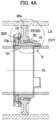
FIG. 4A is a cross-sectional view taken along I-I ofFIG. 2 of the center vent tube support device of the embodiment of the present disclosure. -
FIG. 4B is an enlarged perspective view of part II ofFIG. 4A of the center vent tube support device of the embodiment of the present disclosure. -
FIG. 5A is a diagram for describing the shape of a ring segment forming the center vent tube support device of the embodiment of the present disclosure, and is a diagram showing a ring mid-process body obtained in the middle of a step of manufacturing the ring segment as viewed from the rear. -
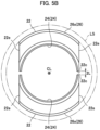
FIG. 5B is a diagram for describing the shape of the ring segment forming the center vent tube support device of the embodiment of the present disclosure, and is a diagram showing a pair of ring segments obtained in the end by machining the ring mid-process body, as viewed from the rear. -
FIG. 6A is a cross-sectional view of a modification of the center vent tube of the embodiment of the present disclosure corresponding toFIG. 4A . -
FIG. 6B is an enlarged perspective view of part III ofFIG. 6A of the modification of the center vent tube of the embodiment of the present disclosure. - Hereinafter, an embodiment and an alternative configuration of the present invention will be described in detail with reference to the drawings.
-
FIG. 1 is a schematic cross-sectional view of the turbofan engine TF adopting a center vent tube support device (hereinafter simply referred to as support device) 1 of the embodiment of the present disclosure. Note that since the configuration of the turbofan engine TF has already been described in Background Art, description is omitted herein. - The support device 1 is used for supporting the center vent tube CVT to the inside of the low pressure shaft LS (main shaft) of the turbofan engine TF, and three support devices 1 are placed along the axial direction in the example shown in
FIG. 1 . Note that the number of support devices 1 to be placed can be selected appropriately to prevent resonance of the center vent tube CVT during operation of the engine. - In the following description, in a state where the support device 1 is attached to the turbofan engine TF, the front side of the engine (upstream side) and the rear side of the engine (downstream side) are referred to as the front side and the rear side of the support device 1 (and its components).
-
FIGS. 2 to 4B are diagrams for describing the support device 1 of the embodiment of the present disclosure, whereFIG. 2 shows four orthogonal views (front view, side view, rear view, and bottom view) of an assembled state,FIG. 3 is an exploded perspective view,FIG. 4A is a cross-sectional view taken along I-I ofFIG. 2 , andFIG. 4B is an enlarged perspective view of part II ofFIG. 4A . - The support device 1 is formed of a
sleeve 10, aring 20, and a nut 30 (in particular, seeFIG. 3 ). - As shown in
FIG. 4A , thesleeve 10 is an annular member placed outside the center vent tube CVT so as to surround the center vent tube CVT, and is formed of a cylindricalinner wall portion 12, aradial wall portion 14 that rises radially outward from the front end of theinner wall portion 12, and anouter wall portion 16 that protrudes rearward from the outer edge of the radial wall portion 14 (in particular, seeFIGS. 3 and4B ). - The
inner wall portion 12 is formed as a cylindrical surface, has aninner surface 12i that comes into contact with an outer surface of the center vent tube CVT and an outer surface 12o, and athread portion 12t that meshes with athread portion 30t of thenut 30 to be described later is provided in the outer surface 12o. Additionally, multiple (three in the example ofFIG. 3 ) rearwardly protrudingtabs 12p are provided at regular intervals in the circumferential direction at the rear end of theinner wall portion 12. - The
radial wall portion 14 has a partially cut ring shape. Twoside surfaces 14e corresponding to the cut surfaces are planes parallel to a plane including an axis CL, and are spaced from the plane at an equal distance (offset distance). Theouter wall portion 16 protrudes rearward from each of the two arc-shaped portions of the outer edge of theradial wall portion 14. - Each of the two
outer wall portions 16 is an arc-shaped part having aninner surface 16i that faces the outer surface 12o of theinner wall portion 12. Ahole 16a that radially penetrates theouter wall portion 16 while straddling theradial wall portion 14 is provided in a circumferential center portion of theouter wall portion 16. Additionally, ahole 12a formed on the same axis as thehole 16a and having a slightly smaller diameter is formed so as to straddle and penetrate theinner wall portion 12 and theradial wall portion 14. - Also, a
positioning pin 10p is press-fitted into thehole 12a. Thepositioning pin 10p is press-fitted such that a radially inner end face thereof is located slightly radially outward of theinner surface 12i of theinner wall portion 12. A radially outer part of thepositioning pin 10p is formed to be accommodated in a cutout 24Fn of aring segment 22 to be described later in an assembled state of the support device 1. Note that at the time of press-fitting, thepositioning pin 10p is inserted from the radially outer side through thehole 16a having a slightly larger diameter than thehole 12a. - As shown in
FIG. 3 , thering 20 is a member formed of a pair ofring segments 22, and eachring segment 22 is formed of a radiallyinner bore portion 24, a radiallyouter rim portion 26, and aweb portion 28 that extends radially between thebore portion 24 and therim portion 26 to connect the portions. - The
bore portion 24 is a cylindrical part formed of portions protruding to the front and rear from the inner end of theweb portion 28. A rear portion of aninner surface 24i of thebore portion 24 is formed as a part of a side surface (conical surface) of a cone (first cone) having a vertex at the front on the axis CL. Additionally, aportion 24F of thebore portion 24 that protrudes frontward has an outer surface formed as a part of a cylindrical surface having a smaller diameter than the diameter of theinner surface 16i of theouter wall portion 16 of thesleeve 10, and an inner surface formed as a part of a cylindrical surface having a larger diameter than the outer surface 12o of theinner wall portion 12 of thesleeve 10. Moreover, theportion 24F includes a groove 24Fg extending over the entire circumference in an outer surface thereof, and includes the cutout 24Fn penetrating theportion 24F in the radial direction in a circumferential center portion of the front end thereof. The cutout 24Fn is formed in a size that can at least partially accommodate theaforementioned positioning pin 10p. - The
rim portion 26 is a cylindrical part formed of portions protruding to the front and rear from the outer end of theweb portion 28. An outer surface (supporting surface) 26o of therim portion 26 is formed as a part of a cylindrical surface having a diameter equal to the inner diameter of the low pressure shaft LS. - Here, the shape of the
ring segment 22 as viewed from the direction of the axis CL will be described with reference toFIGS. 5A and5B . Here,FIG. 5A is a diagram showing a rear view of aring mid-process body 21 obtained in the middle of a step of manufacturing thering segment 22, andFIG. 5B is a diagram showing a rear view of the pair ofring segments 22 obtained in the end after machining thering mid-process body 21. - As shown in
FIG. 5A , thering mid-process body 21 has a partially cut ring shape. Twoside surfaces 21e corresponding to the cut surfaces are planes parallel to a first plane (not shown) including the axis CL, and are spaced from the first plane at an equal distance (first distance). Here, the first distance is set substantially equivalent to the aforementioned offset distance of theradial wall portion 14 of thesleeve 10. As a result, the distance between the twoside surfaces 21e of the ring mid-process body 21 (width of ring mid-process body 21) is substantially equivalent to the distance between the twoside surfaces 14e of theradial wall portion 14 of the sleeve 10 (width of radial wall portion 14). - Additionally, outer surfaces 21o (two) of the
ring mid-process body 21 are formed as parts of a cylindrical surface having a diameter equal to the inner diameter of the low pressure shaft LS. A rear portion of aninner surface 21i of thering mid-process body 21 is formed as a part of a side surface (conical surface) of a cone (first cone) having a vertex at the front on the axis CL. Since the outer surface 21o and theinner surface 21i thus have an axisymmetric shape, they can be formed by turning, for example. - By cutting the
ring mid-process body 21 in the above-mentioned form along two planes S shown inFIG. 5A , the pair ofring segments 22 shown inFIG. 5B are obtained. Here, the two planes S are planes parallel to a plane S0 (second plane) that includes the axis CL and is perpendicular to theside surface 21e of the ring mid-process body 21 (in other words, perpendicular to the aforementioned first plane), and are spaced from the plane S0 at an equal distance L (second distance). Note that after thering mid-process body 21 is cut along the two planes S, the outer surface 21o, theinner surface 21i, and theside surface 21e of thering mid-process body 21 become the outer surface 26o (of rim portion 26), theinner surface 24i (of bore portion 24), and aside surface 22e of thering segment 22, respectively. - Here, the diameter of the cylindrical surface forming each of the outer surface and the inner surface of the
frontwardly protruding portion 24F of thebore portion 24 of eachring segment 22, and the aforementioned distance L are set to such values that allow theportion 24F to be accommodated in a space defined by theinner wall portion 12, theradial wall portion 14, and theouter wall portion 16 of thesleeve 10 when end faces 22c (surfaces corresponding to planes S) of the pair ofring segments 22 are brought into contact with each other. - In the
ring 20 formed of the pair ofring segments 22 manufactured in the above manner, when the end faces 22c of the tworing segments 22 are separated by adistance 2L while maintaining a parallel state, the outer surface 26o (of rim portion 26) of thering 20 comes into close contact with the inner surface of the low pressure shaft LS, as shown inFIG. 5B . - Note that the
ring 20 includes aconnection ring 20R provided around the outer surface of thefrontwardly protruding portion 24F of thebore portion 24 to keep the pair ofring segments 22 close to each other as will be described later, when assembling the support device 1. The groove 24Fg included in thebore portion 24 is formed so that theconnection ring 20R can be fit thereinto. - The
connection ring 20R is an elastic annular member, and a resin ring or a metal piston ring may be used. By placing the pair ofring segments 22 with the end faces 22c in contact with each other and fitting theconnection ring 20R into the groove 24Fg of thebore portion 24 while expanding the inner diameter of theconnection ring 20R, the pair ofring segments 22 can be held close to each other. This can prevent thering 20 formed of the pair ofring segments 22 from falling apart when the temporarily assembled support device 1 is inserted into the low pressure shaft LS and moved to a predetermined axial position, as will be described later. - While the
connection ring 20R is a member necessary for assembling the support device 1 as described above, it is a member that does not have any specific function after assembly, that is, during operation of the engine. On the other hand, theconnection ring 20R is stretched radially outward by centrifugal force that acts during operation of the engine and may break, and the broken piece may fall into a space between the low pressure shaft LS and the center vent tube CVT from the groove 24Fg. To prevent such a situation, the aforementionedouter wall portion 16 of thesleeve 10 is provided to cover theconnection ring 20R fitted into the groove 24Fg from the radially outer side in the assembled state of the support device 1. - The
nut 30 is an annular member, and has aninner surface 30i and an outer surface 30o formed as substantially cylindrical surfaces. Thethread portion 30t that meshes with thethread portion 12t provided on the outer surface 12o of theinner wall portion 12 of thesleeve 10 is provided on theinner surface 30i. Additionally, a front portion of the outer surface 30o is formed as a part of a side surface (conical surface) of a cone (second cone) having a vertex at the front on the axis CL. Meanwhile, multiple (three in the example ofFIG. 3 ) rearwardly protrudingtabs 30p are provided at regular intervals in the circumferential direction at the rear end of thenut 30. - Here, the first cone whose side surface forms the rear portion of the
inner surface 24i of thebore portion 24 of thering segment 22 and the second cone whose side surface forms the front portion of the outer surface 30o of thenut 30 are geometrically the same cone. That is, the conical surface forming the rear portion of theinner surface 24i of thebore portion 24 of thering segment 22 and the conical surface forming the front portion of the outer surface 30o of thenut 30 have an equivalent vertex angle. - Accordingly, when the
nut 30 is screwed onto the outer periphery of theinner wall portion 12 of thesleeve 10 and moved forward while restricting axial movement of thering segment 22 with the rear portion of theinner surface 24i of thebore portion 24 of thering segment 22 and the front portion of the outer surface 30o of thenut 30 in contact with each other, the front portion (pressurizing surface) of the outer surface 30o of thenut 30 pushes up the rear portion (bearing surface) of theinner surface 24i of thebore portion 24 of thering segment 22 to the radially outer side while in close contact therewith. By using this to push the outer surface 26o of therim portion 26 of thering segment 22 against the inner surface of the low pressure shaft LS and generating reactive force, thering segment 22 can be held, and therefore radial displacement of the center vent tube CVT fitted to the inner side of thesleeve 10 can be restricted. - Hereinafter, the procedure of assembling the support device 1 configured in the above manner and mounting the support device 1 to the inside of the low pressure shaft LS of the turbofan engine TF will be described.
- (1) Place the pair of
ring segments 22 with the end faces 22c in contact with each other, and fit theconnection ring 20R into the groove 24Fg of thebore portion 24 while expanding the inner diameter of theconnection ring 20R. With this, the pair ofring segments 22 can be held close to each other. - (2) Fit the pair of
ring segments 22 unified by theconnection ring 20R into thesleeve 10 from the rear. That is, bring the pair ofring segments 22 close to theradial wall portion 14 of thesleeve 10 such that theinner surface 24i of thebore portion 24 passes the outer side of the outer surface 12o of theinner wall portion 12 of thesleeve 10. At this time, adjust the circumferential position of both members, so that the cutout 24Fn provided at the front end of thebore portion 24 of eachring segment 22 is in phase with thepositioning pin 10p press-fitted into thehole 12a of thesleeve 10. As a result, when the front surface of thebore portion 24 of eachring segment 22 comes into contact with theradial wall portion 14 of thesleeve 10, thepositioning pin 10p is accommodated in the cutout 24Fn, and relative movement in the circumferential direction of thesleeve 10 and eachring segment 22 is restricted. Accordingly, when the temporarily assembled support device 1 is inserted into the low pressure shaft LS of the turbofan engine TF as will be described later, the support device 1 can be securely passed through a small-diameter portion SD of the low pressure shaft LS by keeping theside surface 14e of theradial wall portion 14 of thesleeve 10 and theside surface 22e of thering segment 22 parallel to each other, and reducing the projected shape in the direction of the axis of the turbofan engine TF. - (3) Screw the
nut 30 into the outer surface 12o of theinner wall portion 12 of thesleeve 10 to a position where the front portion (conical surface) of the outer surface 30o and the rear portion (conical surface) of theinner surface 24i of thebore portion 24 of thering segment 22 come into contact with each other. At this time, the end faces 22c of the pair ofring segments 22 are still in contact with each other. - (4) Insert the assembly in the state of (3) into the low pressure shaft LS of the turbofan engine TF from the rear.
- Here, the low pressure shaft LS has, in the vicinity of the rear end thereof, the small-diameter portion SD (see
FIG. 1 ) whose inner diameter is smaller than that of the position where the support device 1 is to be placed. In order to pass the support device 1 through such a small-diameter portion SD, theradial wall portion 14 of thesleeve 10 and thering 20 formed of the pair ofring segments 22 have a partially cut ring shape as described above. - As a result, in the assembly in the state of (3), the diameter of a circle circumscribing the projected shape (Specifically, shape shown in bottom view of
FIG. 2 . Hereinafter referred to as vertical projected shape) of thering segment 22 in a direction perpendicular to theend face 22c of the ring segment 22 (i.e., vertical direction inFIG. 2 ) is smaller than the diameter of a circle circumscribing the projected shape (Specifically, shape of rear view ofFIG. 2 where tworing segments 22 are brought close to each other and end faces 22c are in contact with each other. Hereinafter referred to as axial projected shape) of thering segment 22 in the axis CL direction. The diameter of a circle circumscribing the vertical projected shape of the assembly in the state of (3) is set smaller than the diameter of the small-diameter portion SD of the low pressure shaft LS. That is, the shape of theradial wall portion 14 of thesleeve 10 and thering mid-process body 21 which is the state of the pair ofring segments 22 before machining, specifically, the position of the plane along which to cut the original ring (i.e., offset distance and first distance), is selected such that the vertical projected shape of the assembly in the state of (3) satisfies the condition described above. - Since the
sleeve 10 and the pair ofring segments 22 are configured in the above manner, when the assembly in the state of (3) is rotated 90 degrees to the rear (see arrows shown in side view ofFIG. 2 ), for example, from the state where its axis CL direction coincides with the direction of the axis of the turbofan engine TF, the projected shape in the direction of the axis of the turbofan engine TF changes from the axial projected shape to the vertical projected shape, and is downsized. Hence, the assembly can be passed through the small-diameter portion SD of the low pressure shaft LS as shown as an image in the bottom view ofFIG. 2 . - After passing the assembly in the state of (3) through the small-diameter portion SD in this manner, insert the assembly further into the low pressure shaft LS, and when it reaches the position where the support device 1 is to be placed, rotate the assembly 90 degrees in a direction opposite to the aforementioned direction. Then, by using an appropriate jig, hold the assembly in the state of (3) and the low pressure shaft LS in a substantially coaxial state.
- (5) Insert a dual-cylinder fastening jig formed of an internal cylinder including, at the tip end thereof, the same number of claws in the same radial position as the
tabs 12p of thesleeve 10, and an external cylinder including, at the tip end thereof, the same number of claws in the same radial position as thetabs 30p of thenut 30 into the low pressure shaft LS from the rear. Screw thenut 30 further into the outer surface 12o of theinner wall portion 12 of thesleeve 10 by bringing the claws of the internal cylinder into contact with thetabs 12p in the circumferential direction to restrict rotation of thesleeve 10, and bringing the claws of the external cylinder into contact with thetabs 30p in the circumferential direction and rotating thenut 30. - At this time, although the front portion (pressurizing surface) of the outer surface 30o of the
nut 30 formed as a conical surface pushes forward the rear portion (bearing surface) of theinner surface 24i of thebore portion 24 of thering segment 22 formed as the conical surface having the same vertex angle as the above conical surface, since the front surface of thebore portion 24 is in contact with theradial wall portion 14 of thesleeve 10 and thereby restricted from moving in the axial direction, thering segment 22 is pushed up radially outward. - When the
nut 30 is further screwed in this manner, in the end, the outer surface 26o of therim portion 26 of eachring segment 22 comes into contact with the inner surface of the low pressure shaft LS. When the external cylinder of the fastening jig is further rotated from this state until a predetermined torque is applied, the outer surface 26o of therim portion 26 of eachring segment 22 receives a predetermined degree of reactive force from the inner surface of the low pressure shaft LS. Thus, the support device 1 is mounted in the proper state. - After mounting a predetermined number of the support devices 1 in the above manner onto predetermined positions, the center vent tube CVT is inserted into the low pressure shaft LS, and is supported by the
inner surface 12i of theinner wall portion 12 of thesleeve 10 of the support devices 1. - As has been described, the support device 1 of the embodiment of the present disclosure is configured such that the
ring 20 placed between the center vent tube CVT and the main shaft (low pressure shaft LS) through thesleeve 10 is formed of the pair ofring segments 22, and comes into contact with the inner surface of the main shaft on the supporting surface (outer surface 26o ofrim portion 26 of ring segment 22) formed as a part of a cylindrical surface having a diameter equal to the inner diameter of the main shaft. - Accordingly, when bringing the supporting surface of the
ring segment 22 into contact with the inner surface of the main shaft at the time of assembly of the support device 1, eachring segment 22 only moves in the radial direction and does not deform. Additionally, even after assembly, since the supporting surface of thering segment 22 is in close contact with the inner surface of the main shaft, there is no fear of deformation. Hence, thesleeve 10 placed between thering segment 22 and the center vent tube CVT is also unlikely to deform. - As has been described, in the support device 1 of the embodiment of the present disclosure, the contacting state between the
ring 20 and the main shaft, and between thesleeve 10 and the center vent tube CVT are both even in the circumferential direction. As a result, an excellent effect of preventing transmission of abnormal load between the members and preventing abrasion of the contact surface can be achieved. - Additionally, while the above description has been given by using the example in which, as a method of restricting relative movement of the
sleeve 10 and thering segment 22 in the circumferential direction, thepositioning pin 10p is fixed (press-fitted intohole 12a) to thesleeve 10 and the cutout 24Fn accommodating thepositioning pin 10p is provided in the ring segment 22 (front end of bore portion 24), other configurations can be adopted. A modification adopting an alternative configuration is shown inFIGS. 6A and6B . - In the modification, a
positioning pin 110p is press-fitted into ahole 128a axially penetrating aweb portion 128 of aring segment 122 and fixed in a frontwardly protruding state. Additionally, acutout 116n radially penetrating while straddling aradial wall portion 114 and anouter wall portion 116 is provided in a circumferential center portion of asleeve 110. - With this configuration, in an assembled state of a
support device 101, thepositioning pin 110p is accommodated in thecutout 116n, so that relative movement of thesleeve 110 and eachring segment 122 in the circumferential direction can be restricted. -
- 1
- center vent tube support device
- 10
- sleeve
- 20
- ring
- 22
- ring segment
- 24
- bore portion (of ring segment)
- 24i
- inner surface (bearing surface) (of bore portion)
- 26
- rim portion (of ring segment)
- 26o
- outer surface (supporting surface) (of rim portion)
- 30
- nut
- 30o
- outer surface (pressurizing surface) (of nut)
- TF
- turbofan engine
- LS
- low pressure shaft (main shaft)
- CVT
- center vent tube
Claims (1)
- A turbofan engine (TF) comprising a hollow low-pressure shaft (LS) and a support device (1) for supporting a center vent tube (CVT) inside the low-pressure shaft (LS), the support device (1) comprising:a sleeve (10, 110);a ring (20) formed of a pair of ring segments (22, 122) and placed between the sleeve (10) and the low-pressure shaft (LS); andan annular nut (30) for axially fixing the ring segments (22, 122) to the sleeve (10, 110) and for radially pushing the ring segments (22, 122) against an inner diameter of the low-pressure shaft (LS), wherein:the sleeve (10, 110) comprises an inner wall portion (12), a radial wall portion (14, 114) extending radially outward from a front end of the inner wall portion (12), and an outer wall portion (16, 116),the inner wall portion (12) has an inner surface (12i) and an outer surface (12o), the inner surface (12i) is formed as a cylindrical surface and comes into contact with an outer surface of the center vent tube (CVT), the radial wall portion (14) has a partially cut ring shape and includes a pair of side surfaces (14e) formed as planes parallel to a first plane including an axis (CL), whose direction coincides with the direction of the axis of the turbofan engine (TF) and each spaced from the first plane at a first distance,the nut (30) includes an inner surface (30i) provided with a thread portion (30t) that meshes with a thread portion (12t) provided on the outer surface (12o), and an outer surface (30o) having a pressurizing surface formed as a conical surface, the inner surface (30i) and the outer surface (30o) are formed as substantially cylindrical surfaces,each of the ring segments (22, 122) is formed of a radially inner cylindrical bore portion (24), a radially outer cylindrical rim portion (26), and a web portion (28, 128) that extends radially between the bore portion (24) and the rim portion (26) to connect the portions (24, 26) and includesa supporting surface that is formed by at least a part of an outer surface (26o) of the rim portion (26) as a part of a cylindrical surface having a diameter equal to the inner diameter of the low-pressure shaft (LS) in a portion where the support device (1) is to be installed,a bearing surface formed by at least a part of an inner surface (24i) of the bore portion (24) as a part of a conical surface having a vertex angle equal to that of the conical surface forming the pressurizing surface,a pair of side surfaces (22e) formed as planes parallel to the first plane and each spaced from the first plane at the first distance, anda pair of end faces (22c) formed as planes each spaced from a second plane (S0) including the axis (CL) and perpendicular to the first plane at a second distance (L);characterized in that:the outer wall portion (16) of the sleeve (10) protrudes rearward from an outer edge of the radial wall portion (14), the outer edge being formed as two arc-shaped portions and the outer wall portion (16) being formed of two arc-shaped parts, an outer hole (16a) radially penetrates the outer wall portion (16), the outer hole (16a) is provided in a circumferential center portion of the outer wall portion (16) and is formed on the same axis as an inner hole (12a), the inner hole (12a) straddling and penetrating the inner wall portion (12) and the radial wall portion (14) of the sleeve (10),a positioning pin (10p) is press-fitted into the inner hole (12a), a cutout (24Fn) accommodating the positioning pin (10p) is provided in one of the ring segments (22) or a positioning pin (110p) is press-fitted into an axial hole (128a) axially penetrating the web portion (128) of the ring segment (122) and fixed in a frontwardly protruding state, a cutout (116n) radially penetrating while straddling the radial wall portion (114) and the outer wall portion (116) is provided in a circumferential center portion of the sleeve (110), whereinin a state where a front surface of the bore portion (24) of each of the ring segments (22) comes into contact with the radial wall portion (14) of the sleeve (10), the positioning pin (10p) and the cutout (24Fn) work in relation with each other to restrict relative movement of the sleeve (10) and the ring segments (22) in the circumferential direction and keep the side surfaces (14e) of the radial wall portion (14) of the sleeve (10) and the side surfaces (22e) of the ring segment (22) parallel to each other, whereinthe pressurizing surface of the nut (30) is configured to push up the bearing surface of the ring segment (22) radially outward when screwing the nut (30) on the sleeve (10) forward with the pressurizing surface of the nut (30) and the bearing surface of the ring segment (22) being in contact with each other, whereinthe low-pressure shaft (LS) has, in the vicinity of the rear end thereof, a small-diameter portion (SD) representing the smallest-diameter portion of the low-pressure shaft (LS), whose inner diameter is smaller than that of the position where the support device (1) is to be placed, and whereinthe partially cut ring shape of the radial wall portion (14) of the sleeve (10) and of the pair of ring segments (22) are configured such that in an assembly state where the end faces (22c) of the pair of ring segments (22) are brought into contact with each other and a connection ring (20R) is provided around an outer surface of the bore portion (24) of the pair of ring segments (22);a diameter of a circle circumscribing a projected shape of the support device (1) in a direction perpendicular to the second plane (S0) is smaller than the inner diameter of the low-pressure shaft (LS) at the small-diameter portion (SD).
Applications Claiming Priority (2)
| Application Number | Priority Date | Filing Date | Title |
|---|---|---|---|
| JP2017192744 | 2017-10-02 | ||
| PCT/JP2018/035769 WO2019069769A1 (en) | 2017-10-02 | 2018-09-26 | Center vent tube support device for turbo fan engine |
Publications (3)
| Publication Number | Publication Date |
|---|---|
| EP3693559A1 EP3693559A1 (en) | 2020-08-12 |
| EP3693559A4 EP3693559A4 (en) | 2021-01-27 |
| EP3693559B1 true EP3693559B1 (en) | 2025-06-25 |
Family
ID=65995059
Family Applications (1)
| Application Number | Title | Priority Date | Filing Date |
|---|---|---|---|
| EP18863980.1A Active EP3693559B1 (en) | 2017-10-02 | 2018-09-26 | Center vent tube support device for turbo fan engine |
Country Status (4)
| Country | Link |
|---|---|
| US (1) | US11248496B2 (en) |
| EP (1) | EP3693559B1 (en) |
| JP (1) | JP6864273B2 (en) |
| WO (1) | WO2019069769A1 (en) |
Families Citing this family (1)
| Publication number | Priority date | Publication date | Assignee | Title |
|---|---|---|---|---|
| JP7426859B2 (en) * | 2020-03-12 | 2024-02-02 | 本田技研工業株式会社 | Support jig for joining |
Family Cites Families (11)
| Publication number | Priority date | Publication date | Assignee | Title |
|---|---|---|---|---|
| US5205189A (en) * | 1990-12-17 | 1993-04-27 | General Electric Company | Engine shaft balance assembly |
| FR2817289B1 (en) * | 2000-11-30 | 2003-01-31 | Snecma Moteurs | DEVICE FOR CENTERING A TUBE IN A TURBINE SHAFT |
| FR2926604B1 (en) * | 2008-01-23 | 2010-03-26 | Snecma | CENTERING A WORKPIECE WITHIN A ROTOR SHAFT IN A TURBOMACHINE |
| FR2957973B1 (en) * | 2010-03-26 | 2013-04-12 | Snecma | TURBOREACTOR DEGASSING TUBE, METHOD OF MOUNTING SUCH TUBE AND TURBOREACTOR WITH SUCH A TUBE |
| CN202926472U (en) * | 2012-11-15 | 2013-05-08 | 中航商用航空发动机有限责任公司 | Turbine machine shaft inner pipe balancing and centering device |
| FR3007788B1 (en) * | 2013-06-28 | 2015-07-24 | Snecma | IMPROVED COUPLING SYSTEM FOR TURBINE SHAFT WITH TURBOMACHINE DEGASSING TUBE |
| FR3008135B1 (en) * | 2013-07-08 | 2017-05-26 | Snecma | CENTERING A WORKPIECE WITHIN A ROTOR SHAFT IN A TURBOMACHINE |
| JP6215740B2 (en) * | 2014-03-14 | 2017-10-18 | 本田技研工業株式会社 | Part fastening structure |
| EP2933432A1 (en) * | 2014-04-15 | 2015-10-21 | Siemens Aktiengesellschaft | Rotor with axially secured support ring |
| EP3176407B1 (en) | 2014-11-14 | 2019-05-15 | IHI Corporation | Jet engine |
| JP6455179B2 (en) * | 2015-01-26 | 2019-01-23 | 株式会社Ihi | Center vent tube alignment mechanism and center vent tube support device |
-
2018
- 2018-09-26 EP EP18863980.1A patent/EP3693559B1/en active Active
- 2018-09-26 JP JP2019546655A patent/JP6864273B2/en active Active
- 2018-09-26 WO PCT/JP2018/035769 patent/WO2019069769A1/en not_active Ceased
-
2020
- 2020-03-06 US US16/810,922 patent/US11248496B2/en active Active
Also Published As
| Publication number | Publication date |
|---|---|
| EP3693559A1 (en) | 2020-08-12 |
| WO2019069769A1 (en) | 2019-04-11 |
| US11248496B2 (en) | 2022-02-15 |
| JPWO2019069769A1 (en) | 2020-01-23 |
| JP6864273B2 (en) | 2021-04-28 |
| EP3693559A4 (en) | 2021-01-27 |
| US20200208539A1 (en) | 2020-07-02 |
Similar Documents
| Publication | Publication Date | Title |
|---|---|---|
| EP2157289B1 (en) | Pumping impeller oil seal | |
| US7458202B2 (en) | Lubrication system for a counter-rotating turbine engine and method of assembling same | |
| US7296398B2 (en) | Counter-rotating turbine engine and method of assembling same | |
| CA2659823C (en) | Thrust bearing housing for a gas turbine engine | |
| EP3719266B1 (en) | Assembly for a bearing compartment of a gas turbine engine | |
| EP2855892B1 (en) | Mid-turbine frame for a gas turbine engine comprising a seal land | |
| EP3045668A1 (en) | Cooling passages for a mid-turbine frame | |
| CA2958347A1 (en) | Intermittent spigot joint for gas turbine engine casing connection | |
| EP3093431A1 (en) | Intershaft integrated seal and lock-nut | |
| EP3070273A1 (en) | Cooling passages for a mid-turbine frame of a gas turbine engine | |
| US9022741B2 (en) | System for securing two tubular components one in the other, carrying a roller bearing | |
| EP2971820B1 (en) | Rolling element bearing configured with a channel and one or more fluid passages | |
| EP3045669B1 (en) | Cooling passages for a mid-turbine frame | |
| EP1087101B1 (en) | Coupling assembly and method for connecting air ducts in gas turbine rotors | |
| US11248496B2 (en) | Center vent tube support device of turbofan engine | |
| US9957799B2 (en) | Balance ring for gas turbine engine | |
| EP3524783B1 (en) | Aircraft engine seal carrier including anti-rotation feature | |
| EP3401562B1 (en) | Bearing with non-uniform cage clearance | |
| EP4012162B1 (en) | Rotating sleeve controlling clearance of seal assembly of gas turbine engine | |
| US10138940B2 (en) | Roller bearing cage for use in a gearbox | |
| US9644487B2 (en) | Fixed turbine engine receiver part comprising an assembly for holding ancillary systems in position inside a fixed hollow shaft | |
| EP3054090B1 (en) | Gas turbine engines with internally stretched tie shafts |
Legal Events
| Date | Code | Title | Description |
|---|---|---|---|
| STAA | Information on the status of an ep patent application or granted ep patent |
Free format text: STATUS: THE INTERNATIONAL PUBLICATION HAS BEEN MADE |
|
| PUAI | Public reference made under article 153(3) epc to a published international application that has entered the european phase |
Free format text: ORIGINAL CODE: 0009012 |
|
| STAA | Information on the status of an ep patent application or granted ep patent |
Free format text: STATUS: REQUEST FOR EXAMINATION WAS MADE |
|
| 17P | Request for examination filed |
Effective date: 20200402 |
|
| AK | Designated contracting states |
Kind code of ref document: A1 Designated state(s): AL AT BE BG CH CY CZ DE DK EE ES FI FR GB GR HR HU IE IS IT LI LT LU LV MC MK MT NL NO PL PT RO RS SE SI SK SM TR |
|
| AX | Request for extension of the european patent |
Extension state: BA ME |
|
| DAV | Request for validation of the european patent (deleted) | ||
| DAX | Request for extension of the european patent (deleted) | ||
| A4 | Supplementary search report drawn up and despatched |
Effective date: 20210113 |
|
| RIC1 | Information provided on ipc code assigned before grant |
Ipc: F02C 7/00 20060101ALI20201222BHEP Ipc: F01D 25/00 20060101AFI20201222BHEP Ipc: F01D 5/02 20060101ALI20201222BHEP |
|
| STAA | Information on the status of an ep patent application or granted ep patent |
Free format text: STATUS: EXAMINATION IS IN PROGRESS |
|
| 17Q | First examination report despatched |
Effective date: 20221221 |
|
| GRAP | Despatch of communication of intention to grant a patent |
Free format text: ORIGINAL CODE: EPIDOSNIGR1 |
|
| STAA | Information on the status of an ep patent application or granted ep patent |
Free format text: STATUS: GRANT OF PATENT IS INTENDED |
|
| INTG | Intention to grant announced |
Effective date: 20250319 |
|
| GRAS | Grant fee paid |
Free format text: ORIGINAL CODE: EPIDOSNIGR3 |
|
| GRAA | (expected) grant |
Free format text: ORIGINAL CODE: 0009210 |
|
| STAA | Information on the status of an ep patent application or granted ep patent |
Free format text: STATUS: THE PATENT HAS BEEN GRANTED |
|
| AK | Designated contracting states |
Kind code of ref document: B1 Designated state(s): AL AT BE BG CH CY CZ DE DK EE ES FI FR GB GR HR HU IE IS IT LI LT LU LV MC MK MT NL NO PL PT RO RS SE SI SK SM TR |
|
| REG | Reference to a national code |
Ref country code: GB Ref legal event code: FG4D |
|
| REG | Reference to a national code |
Ref country code: CH Ref legal event code: EP |
|
| REG | Reference to a national code |
Ref country code: DE Ref legal event code: R096 Ref document number: 602018083001 Country of ref document: DE |
|
| REG | Reference to a national code |
Ref country code: CH Ref legal event code: EP |
|
| REG | Reference to a national code |
Ref country code: IE Ref legal event code: FG4D |
|
| PG25 | Lapsed in a contracting state [announced via postgrant information from national office to epo] |
Ref country code: FI Free format text: LAPSE BECAUSE OF FAILURE TO SUBMIT A TRANSLATION OF THE DESCRIPTION OR TO PAY THE FEE WITHIN THE PRESCRIBED TIME-LIMIT Effective date: 20250625 |
|
| REG | Reference to a national code |
Ref country code: LT Ref legal event code: MG9D |
|
| PG25 | Lapsed in a contracting state [announced via postgrant information from national office to epo] |
Ref country code: NO Free format text: LAPSE BECAUSE OF FAILURE TO SUBMIT A TRANSLATION OF THE DESCRIPTION OR TO PAY THE FEE WITHIN THE PRESCRIBED TIME-LIMIT Effective date: 20250925 Ref country code: GR Free format text: LAPSE BECAUSE OF FAILURE TO SUBMIT A TRANSLATION OF THE DESCRIPTION OR TO PAY THE FEE WITHIN THE PRESCRIBED TIME-LIMIT Effective date: 20250926 |
|
| PG25 | Lapsed in a contracting state [announced via postgrant information from national office to epo] |
Ref country code: BG Free format text: LAPSE BECAUSE OF FAILURE TO SUBMIT A TRANSLATION OF THE DESCRIPTION OR TO PAY THE FEE WITHIN THE PRESCRIBED TIME-LIMIT Effective date: 20250625 |
|
| PG25 | Lapsed in a contracting state [announced via postgrant information from national office to epo] |
Ref country code: HR Free format text: LAPSE BECAUSE OF FAILURE TO SUBMIT A TRANSLATION OF THE DESCRIPTION OR TO PAY THE FEE WITHIN THE PRESCRIBED TIME-LIMIT Effective date: 20250625 |
|
| PGFP | Annual fee paid to national office [announced via postgrant information from national office to epo] |
Ref country code: FR Payment date: 20250924 Year of fee payment: 8 |
|
| PG25 | Lapsed in a contracting state [announced via postgrant information from national office to epo] |
Ref country code: RS Free format text: LAPSE BECAUSE OF FAILURE TO SUBMIT A TRANSLATION OF THE DESCRIPTION OR TO PAY THE FEE WITHIN THE PRESCRIBED TIME-LIMIT Effective date: 20250925 |
|
| PG25 | Lapsed in a contracting state [announced via postgrant information from national office to epo] |
Ref country code: LV Free format text: LAPSE BECAUSE OF FAILURE TO SUBMIT A TRANSLATION OF THE DESCRIPTION OR TO PAY THE FEE WITHIN THE PRESCRIBED TIME-LIMIT Effective date: 20250625 |
|
| REG | Reference to a national code |
Ref country code: NL Ref legal event code: MP Effective date: 20250625 |
|
| PG25 | Lapsed in a contracting state [announced via postgrant information from national office to epo] |
Ref country code: NL Free format text: LAPSE BECAUSE OF FAILURE TO SUBMIT A TRANSLATION OF THE DESCRIPTION OR TO PAY THE FEE WITHIN THE PRESCRIBED TIME-LIMIT Effective date: 20250625 |
|
| PG25 | Lapsed in a contracting state [announced via postgrant information from national office to epo] |
Ref country code: PT Free format text: LAPSE BECAUSE OF FAILURE TO SUBMIT A TRANSLATION OF THE DESCRIPTION OR TO PAY THE FEE WITHIN THE PRESCRIBED TIME-LIMIT Effective date: 20251027 |
|
| REG | Reference to a national code |
Ref country code: AT Ref legal event code: MK05 Ref document number: 1806633 Country of ref document: AT Kind code of ref document: T Effective date: 20250625 |
|
| PG25 | Lapsed in a contracting state [announced via postgrant information from national office to epo] |
Ref country code: IS Free format text: LAPSE BECAUSE OF FAILURE TO SUBMIT A TRANSLATION OF THE DESCRIPTION OR TO PAY THE FEE WITHIN THE PRESCRIBED TIME-LIMIT Effective date: 20251025 |
|
| PG25 | Lapsed in a contracting state [announced via postgrant information from national office to epo] |
Ref country code: AT Free format text: LAPSE BECAUSE OF FAILURE TO SUBMIT A TRANSLATION OF THE DESCRIPTION OR TO PAY THE FEE WITHIN THE PRESCRIBED TIME-LIMIT Effective date: 20250625 Ref country code: SM Free format text: LAPSE BECAUSE OF FAILURE TO SUBMIT A TRANSLATION OF THE DESCRIPTION OR TO PAY THE FEE WITHIN THE PRESCRIBED TIME-LIMIT Effective date: 20250625 |
|
| PG25 | Lapsed in a contracting state [announced via postgrant information from national office to epo] |
Ref country code: CZ Free format text: LAPSE BECAUSE OF FAILURE TO SUBMIT A TRANSLATION OF THE DESCRIPTION OR TO PAY THE FEE WITHIN THE PRESCRIBED TIME-LIMIT Effective date: 20250625 |
|
| PG25 | Lapsed in a contracting state [announced via postgrant information from national office to epo] |
Ref country code: PL Free format text: LAPSE BECAUSE OF FAILURE TO SUBMIT A TRANSLATION OF THE DESCRIPTION OR TO PAY THE FEE WITHIN THE PRESCRIBED TIME-LIMIT Effective date: 20250625 |
|
| PG25 | Lapsed in a contracting state [announced via postgrant information from national office to epo] |
Ref country code: EE Free format text: LAPSE BECAUSE OF FAILURE TO SUBMIT A TRANSLATION OF THE DESCRIPTION OR TO PAY THE FEE WITHIN THE PRESCRIBED TIME-LIMIT Effective date: 20250625 |
|
| PG25 | Lapsed in a contracting state [announced via postgrant information from national office to epo] |
Ref country code: SK Free format text: LAPSE BECAUSE OF FAILURE TO SUBMIT A TRANSLATION OF THE DESCRIPTION OR TO PAY THE FEE WITHIN THE PRESCRIBED TIME-LIMIT Effective date: 20250625 |
|
| PG25 | Lapsed in a contracting state [announced via postgrant information from national office to epo] |
Ref country code: ES Free format text: LAPSE BECAUSE OF FAILURE TO SUBMIT A TRANSLATION OF THE DESCRIPTION OR TO PAY THE FEE WITHIN THE PRESCRIBED TIME-LIMIT Effective date: 20250625 |
|
| PG25 | Lapsed in a contracting state [announced via postgrant information from national office to epo] |
Ref country code: RO Free format text: LAPSE BECAUSE OF FAILURE TO SUBMIT A TRANSLATION OF THE DESCRIPTION OR TO PAY THE FEE WITHIN THE PRESCRIBED TIME-LIMIT Effective date: 20250625 |
|
| PG25 | Lapsed in a contracting state [announced via postgrant information from national office to epo] |
Ref country code: DK Free format text: LAPSE BECAUSE OF FAILURE TO SUBMIT A TRANSLATION OF THE DESCRIPTION OR TO PAY THE FEE WITHIN THE PRESCRIBED TIME-LIMIT Effective date: 20250625 |
|
| PG25 | Lapsed in a contracting state [announced via postgrant information from national office to epo] |
Ref country code: IT Free format text: LAPSE BECAUSE OF FAILURE TO SUBMIT A TRANSLATION OF THE DESCRIPTION OR TO PAY THE FEE WITHIN THE PRESCRIBED TIME-LIMIT Effective date: 20250625 |
|
| PLBE | No opposition filed within time limit |
Free format text: ORIGINAL CODE: 0009261 |
|
| STAA | Information on the status of an ep patent application or granted ep patent |
Free format text: STATUS: NO OPPOSITION FILED WITHIN TIME LIMIT |
|
| REG | Reference to a national code |
Ref country code: CH Ref legal event code: H13 Free format text: ST27 STATUS EVENT CODE: U-0-0-H10-H13 (AS PROVIDED BY THE NATIONAL OFFICE) Effective date: 20260504 |
|
| REG | Reference to a national code |
Ref country code: CH Ref legal event code: L10 Free format text: ST27 STATUS EVENT CODE: U-0-0-L10-L00 (AS PROVIDED BY THE NATIONAL OFFICE) Effective date: 20260507 |