EP3693338A1 - Système auto-thermique haute pression pour réformer de l'alcool et produire de l'hydrogène, procédé et unités correspondants - Google Patents
Système auto-thermique haute pression pour réformer de l'alcool et produire de l'hydrogène, procédé et unités correspondants Download PDFInfo
- Publication number
- EP3693338A1 EP3693338A1 EP19382085.9A EP19382085A EP3693338A1 EP 3693338 A1 EP3693338 A1 EP 3693338A1 EP 19382085 A EP19382085 A EP 19382085A EP 3693338 A1 EP3693338 A1 EP 3693338A1
- Authority
- EP
- European Patent Office
- Prior art keywords
- auto
- hydrogen
- unit
- alcohol
- oxygen
- Prior art date
- Legal status (The legal status is an assumption and is not a legal conclusion. Google has not performed a legal analysis and makes no representation as to the accuracy of the status listed.)
- Granted
Links
- 239000001257 hydrogen Substances 0.000 title claims abstract description 125
- 229910052739 hydrogen Inorganic materials 0.000 title claims abstract description 125
- LFQSCWFLJHTTHZ-UHFFFAOYSA-N Ethanol Chemical compound CCO LFQSCWFLJHTTHZ-UHFFFAOYSA-N 0.000 title claims abstract description 108
- 238000000034 method Methods 0.000 title claims abstract description 86
- 238000002407 reforming Methods 0.000 title claims abstract description 56
- 125000004435 hydrogen atom Chemical class [H]* 0.000 title 1
- UFHFLCQGNIYNRP-UHFFFAOYSA-N Hydrogen Chemical compound [H][H] UFHFLCQGNIYNRP-UHFFFAOYSA-N 0.000 claims abstract description 93
- 239000007789 gas Substances 0.000 claims abstract description 92
- 238000002453 autothermal reforming Methods 0.000 claims abstract description 66
- 238000000926 separation method Methods 0.000 claims abstract description 44
- 238000002485 combustion reaction Methods 0.000 claims abstract description 36
- 150000002431 hydrogen Chemical class 0.000 claims abstract description 31
- 238000004519 manufacturing process Methods 0.000 claims abstract description 26
- 239000001301 oxygen Substances 0.000 claims description 81
- 229910052760 oxygen Inorganic materials 0.000 claims description 81
- QVGXLLKOCUKJST-UHFFFAOYSA-N atomic oxygen Chemical compound [O] QVGXLLKOCUKJST-UHFFFAOYSA-N 0.000 claims description 79
- XLYOFNOQVPJJNP-UHFFFAOYSA-N water Substances O XLYOFNOQVPJJNP-UHFFFAOYSA-N 0.000 claims description 67
- OKKJLVBELUTLKV-UHFFFAOYSA-N Methanol Chemical compound OC OKKJLVBELUTLKV-UHFFFAOYSA-N 0.000 claims description 66
- VNWKTOKETHGBQD-UHFFFAOYSA-N methane Chemical compound C VNWKTOKETHGBQD-UHFFFAOYSA-N 0.000 claims description 66
- 239000012528 membrane Substances 0.000 claims description 40
- 238000002156 mixing Methods 0.000 claims description 38
- 230000003197 catalytic effect Effects 0.000 claims description 32
- KDLHZDBZIXYQEI-UHFFFAOYSA-N Palladium Chemical compound [Pd] KDLHZDBZIXYQEI-UHFFFAOYSA-N 0.000 claims description 24
- 229910052763 palladium Inorganic materials 0.000 claims description 9
- 230000001965 increasing effect Effects 0.000 claims description 8
- 229910001092 metal group alloy Inorganic materials 0.000 claims description 7
- 238000011084 recovery Methods 0.000 claims description 5
- 229910010293 ceramic material Inorganic materials 0.000 claims description 3
- 229910000990 Ni alloy Inorganic materials 0.000 claims description 2
- 239000000446 fuel Substances 0.000 description 74
- 238000006243 chemical reaction Methods 0.000 description 63
- 239000003054 catalyst Substances 0.000 description 56
- 230000008569 process Effects 0.000 description 47
- 239000000203 mixture Substances 0.000 description 37
- 238000013461 design Methods 0.000 description 25
- 238000007254 oxidation reaction Methods 0.000 description 19
- 230000003647 oxidation Effects 0.000 description 15
- 230000001590 oxidative effect Effects 0.000 description 15
- 239000007800 oxidant agent Substances 0.000 description 14
- CURLTUGMZLYLDI-UHFFFAOYSA-N Carbon dioxide Chemical compound O=C=O CURLTUGMZLYLDI-UHFFFAOYSA-N 0.000 description 13
- 239000000376 reactant Substances 0.000 description 13
- 229910002092 carbon dioxide Inorganic materials 0.000 description 11
- 239000000463 material Substances 0.000 description 11
- 239000000047 product Substances 0.000 description 10
- 229930195733 hydrocarbon Natural products 0.000 description 9
- 150000002430 hydrocarbons Chemical class 0.000 description 9
- 230000005855 radiation Effects 0.000 description 9
- IKHGUXGNUITLKF-UHFFFAOYSA-N Acetaldehyde Chemical compound CC=O IKHGUXGNUITLKF-UHFFFAOYSA-N 0.000 description 8
- 239000004215 Carbon black (E152) Substances 0.000 description 7
- 230000008901 benefit Effects 0.000 description 7
- 238000000746 purification Methods 0.000 description 7
- 230000015572 biosynthetic process Effects 0.000 description 6
- 238000007084 catalytic combustion reaction Methods 0.000 description 6
- 238000000354 decomposition reaction Methods 0.000 description 6
- 238000009413 insulation Methods 0.000 description 6
- 230000010354 integration Effects 0.000 description 6
- 238000012545 processing Methods 0.000 description 6
- 239000011819 refractory material Substances 0.000 description 6
- 239000012530 fluid Substances 0.000 description 5
- 229910052751 metal Inorganic materials 0.000 description 5
- 239000002184 metal Substances 0.000 description 5
- 238000006057 reforming reaction Methods 0.000 description 5
- 238000000629 steam reforming Methods 0.000 description 5
- UUFQTNFCRMXOAE-UHFFFAOYSA-N 1-methylmethylene Chemical compound C[CH] UUFQTNFCRMXOAE-UHFFFAOYSA-N 0.000 description 4
- IJGRMHOSHXDMSA-UHFFFAOYSA-N Atomic nitrogen Chemical compound N#N IJGRMHOSHXDMSA-UHFFFAOYSA-N 0.000 description 4
- NINIDFKCEFEMDL-UHFFFAOYSA-N Sulfur Chemical compound [S] NINIDFKCEFEMDL-UHFFFAOYSA-N 0.000 description 4
- 238000010276 construction Methods 0.000 description 4
- 238000005516 engineering process Methods 0.000 description 4
- 239000002737 fuel gas Substances 0.000 description 4
- 238000010438 heat treatment Methods 0.000 description 4
- 239000011261 inert gas Substances 0.000 description 4
- 238000004088 simulation Methods 0.000 description 4
- UGFAIRIUMAVXCW-UHFFFAOYSA-N Carbon monoxide Chemical compound [O+]#[C-] UGFAIRIUMAVXCW-UHFFFAOYSA-N 0.000 description 3
- 239000001569 carbon dioxide Substances 0.000 description 3
- 229910002091 carbon monoxide Inorganic materials 0.000 description 3
- 238000001666 catalytic steam reforming of ethanol Methods 0.000 description 3
- 239000003153 chemical reaction reagent Substances 0.000 description 3
- 150000001875 compounds Chemical class 0.000 description 3
- 239000007788 liquid Substances 0.000 description 3
- 239000011541 reaction mixture Substances 0.000 description 3
- 239000000126 substance Substances 0.000 description 3
- 238000005496 tempering Methods 0.000 description 3
- 238000012546 transfer Methods 0.000 description 3
- QGZKDVFQNNGYKY-UHFFFAOYSA-N Ammonia Chemical compound N QGZKDVFQNNGYKY-UHFFFAOYSA-N 0.000 description 2
- CIWBSHSKHKDKBQ-JLAZNSOCSA-N Ascorbic acid Chemical compound OC[C@H](O)[C@H]1OC(=O)C(O)=C1O CIWBSHSKHKDKBQ-JLAZNSOCSA-N 0.000 description 2
- MYMOFIZGZYHOMD-UHFFFAOYSA-N Dioxygen Chemical compound O=O MYMOFIZGZYHOMD-UHFFFAOYSA-N 0.000 description 2
- 101100230799 Drosophila melanogaster Coprox gene Proteins 0.000 description 2
- PXHVJJICTQNCMI-UHFFFAOYSA-N Nickel Chemical compound [Ni] PXHVJJICTQNCMI-UHFFFAOYSA-N 0.000 description 2
- 239000005864 Sulphur Substances 0.000 description 2
- 230000003213 activating effect Effects 0.000 description 2
- 238000004458 analytical method Methods 0.000 description 2
- 239000000919 ceramic Substances 0.000 description 2
- 238000009826 distribution Methods 0.000 description 2
- IDGUHHHQCWSQLU-UHFFFAOYSA-N ethanol;hydrate Chemical compound O.CCO IDGUHHHQCWSQLU-UHFFFAOYSA-N 0.000 description 2
- 238000001704 evaporation Methods 0.000 description 2
- 230000008020 evaporation Effects 0.000 description 2
- 239000000945 filler Substances 0.000 description 2
- 238000009434 installation Methods 0.000 description 2
- 238000012986 modification Methods 0.000 description 2
- 230000004048 modification Effects 0.000 description 2
- 229910052757 nitrogen Inorganic materials 0.000 description 2
- 238000013021 overheating Methods 0.000 description 2
- 239000002245 particle Substances 0.000 description 2
- 239000012466 permeate Substances 0.000 description 2
- 238000007670 refining Methods 0.000 description 2
- 230000002441 reversible effect Effects 0.000 description 2
- 239000000523 sample Substances 0.000 description 2
- 229910052717 sulfur Inorganic materials 0.000 description 2
- 239000011593 sulfur Substances 0.000 description 2
- 238000003786 synthesis reaction Methods 0.000 description 2
- 230000001052 transient effect Effects 0.000 description 2
- 238000011144 upstream manufacturing Methods 0.000 description 2
- 125000003158 alcohol group Chemical group 0.000 description 1
- 150000001298 alcohols Chemical class 0.000 description 1
- 229910021529 ammonia Inorganic materials 0.000 description 1
- 239000003225 biodiesel Substances 0.000 description 1
- 230000005540 biological transmission Effects 0.000 description 1
- 238000001651 catalytic steam reforming of methanol Methods 0.000 description 1
- 239000007795 chemical reaction product Substances 0.000 description 1
- 239000011248 coating agent Substances 0.000 description 1
- 238000000576 coating method Methods 0.000 description 1
- 229910017052 cobalt Inorganic materials 0.000 description 1
- 239000010941 cobalt Substances 0.000 description 1
- GUTLYIVDDKVIGB-UHFFFAOYSA-N cobalt atom Chemical compound [Co] GUTLYIVDDKVIGB-UHFFFAOYSA-N 0.000 description 1
- 230000006835 compression Effects 0.000 description 1
- 238000007906 compression Methods 0.000 description 1
- 230000001143 conditioned effect Effects 0.000 description 1
- 238000001816 cooling Methods 0.000 description 1
- 239000000498 cooling water Substances 0.000 description 1
- 238000006356 dehydrogenation reaction Methods 0.000 description 1
- 238000011161 development Methods 0.000 description 1
- 239000002283 diesel fuel Substances 0.000 description 1
- 230000009189 diving Effects 0.000 description 1
- 238000011143 downstream manufacturing Methods 0.000 description 1
- 238000005265 energy consumption Methods 0.000 description 1
- 230000002708 enhancing effect Effects 0.000 description 1
- 230000007613 environmental effect Effects 0.000 description 1
- 239000003546 flue gas Substances 0.000 description 1
- 238000011010 flushing procedure Methods 0.000 description 1
- 239000002803 fossil fuel Substances 0.000 description 1
- 230000020169 heat generation Effects 0.000 description 1
- 239000008240 homogeneous mixture Substances 0.000 description 1
- 238000000265 homogenisation Methods 0.000 description 1
- 239000011810 insulating material Substances 0.000 description 1
- 239000012774 insulation material Substances 0.000 description 1
- 238000005259 measurement Methods 0.000 description 1
- 239000003345 natural gas Substances 0.000 description 1
- 229910052759 nickel Inorganic materials 0.000 description 1
- 150000002926 oxygen Chemical class 0.000 description 1
- 239000002574 poison Substances 0.000 description 1
- 231100000614 poison Toxicity 0.000 description 1
- 231100000572 poisoning Toxicity 0.000 description 1
- 230000000607 poisoning effect Effects 0.000 description 1
- 238000010248 power generation Methods 0.000 description 1
- 239000010970 precious metal Substances 0.000 description 1
- 238000002360 preparation method Methods 0.000 description 1
- 230000009467 reduction Effects 0.000 description 1
- 238000005057 refrigeration Methods 0.000 description 1
- 238000004904 shortening Methods 0.000 description 1
- 239000007921 spray Substances 0.000 description 1
- 230000003068 static effect Effects 0.000 description 1
- 238000003860 storage Methods 0.000 description 1
- 230000008016 vaporization Effects 0.000 description 1
- 238000012800 visualization Methods 0.000 description 1
Images


Classifications
-
- C—CHEMISTRY; METALLURGY
- C01—INORGANIC CHEMISTRY
- C01B—NON-METALLIC ELEMENTS; COMPOUNDS THEREOF; METALLOIDS OR COMPOUNDS THEREOF NOT COVERED BY SUBCLASS C01C
- C01B3/00—Hydrogen; Gaseous mixtures containing hydrogen; Separation of hydrogen from mixtures containing it; Purification of hydrogen
- C01B3/02—Production of hydrogen or of gaseous mixtures containing a substantial proportion of hydrogen
- C01B3/32—Production of hydrogen or of gaseous mixtures containing a substantial proportion of hydrogen by reaction of gaseous or liquid organic compounds with gasifying agents, e.g. water, carbon dioxide, air
- C01B3/323—Catalytic reaction of gaseous or liquid organic compounds other than hydrocarbons with gasifying agents
-
- B—PERFORMING OPERATIONS; TRANSPORTING
- B01—PHYSICAL OR CHEMICAL PROCESSES OR APPARATUS IN GENERAL
- B01J—CHEMICAL OR PHYSICAL PROCESSES, e.g. CATALYSIS OR COLLOID CHEMISTRY; THEIR RELEVANT APPARATUS
- B01J8/00—Chemical or physical processes in general, conducted in the presence of fluids and solid particles; Apparatus for such processes
- B01J8/02—Chemical or physical processes in general, conducted in the presence of fluids and solid particles; Apparatus for such processes with stationary particles, e.g. in fixed beds
- B01J8/0242—Chemical or physical processes in general, conducted in the presence of fluids and solid particles; Apparatus for such processes with stationary particles, e.g. in fixed beds the fluid flow within the bed being predominantly vertical
- B01J8/025—Chemical or physical processes in general, conducted in the presence of fluids and solid particles; Apparatus for such processes with stationary particles, e.g. in fixed beds the fluid flow within the bed being predominantly vertical in a cylindrical shaped bed
-
- B—PERFORMING OPERATIONS; TRANSPORTING
- B01—PHYSICAL OR CHEMICAL PROCESSES OR APPARATUS IN GENERAL
- B01J—CHEMICAL OR PHYSICAL PROCESSES, e.g. CATALYSIS OR COLLOID CHEMISTRY; THEIR RELEVANT APPARATUS
- B01J8/00—Chemical or physical processes in general, conducted in the presence of fluids and solid particles; Apparatus for such processes
- B01J8/02—Chemical or physical processes in general, conducted in the presence of fluids and solid particles; Apparatus for such processes with stationary particles, e.g. in fixed beds
- B01J8/0278—Feeding reactive fluids
-
- B—PERFORMING OPERATIONS; TRANSPORTING
- B01—PHYSICAL OR CHEMICAL PROCESSES OR APPARATUS IN GENERAL
- B01J—CHEMICAL OR PHYSICAL PROCESSES, e.g. CATALYSIS OR COLLOID CHEMISTRY; THEIR RELEVANT APPARATUS
- B01J8/00—Chemical or physical processes in general, conducted in the presence of fluids and solid particles; Apparatus for such processes
- B01J8/02—Chemical or physical processes in general, conducted in the presence of fluids and solid particles; Apparatus for such processes with stationary particles, e.g. in fixed beds
- B01J8/04—Chemical or physical processes in general, conducted in the presence of fluids and solid particles; Apparatus for such processes with stationary particles, e.g. in fixed beds the fluid passing successively through two or more beds
- B01J8/0446—Chemical or physical processes in general, conducted in the presence of fluids and solid particles; Apparatus for such processes with stationary particles, e.g. in fixed beds the fluid passing successively through two or more beds the flow within the beds being predominantly vertical
- B01J8/0449—Chemical or physical processes in general, conducted in the presence of fluids and solid particles; Apparatus for such processes with stationary particles, e.g. in fixed beds the fluid passing successively through two or more beds the flow within the beds being predominantly vertical in two or more cylindrical beds
- B01J8/0453—Chemical or physical processes in general, conducted in the presence of fluids and solid particles; Apparatus for such processes with stationary particles, e.g. in fixed beds the fluid passing successively through two or more beds the flow within the beds being predominantly vertical in two or more cylindrical beds the beds being superimposed one above the other
-
- C—CHEMISTRY; METALLURGY
- C01—INORGANIC CHEMISTRY
- C01B—NON-METALLIC ELEMENTS; COMPOUNDS THEREOF; METALLOIDS OR COMPOUNDS THEREOF NOT COVERED BY SUBCLASS C01C
- C01B3/00—Hydrogen; Gaseous mixtures containing hydrogen; Separation of hydrogen from mixtures containing it; Purification of hydrogen
- C01B3/50—Separation of hydrogen or hydrogen containing gases from gaseous mixtures, e.g. purification
- C01B3/501—Separation of hydrogen or hydrogen containing gases from gaseous mixtures, e.g. purification by diffusion
- C01B3/503—Separation of hydrogen or hydrogen containing gases from gaseous mixtures, e.g. purification by diffusion characterised by the membrane
- C01B3/505—Membranes containing palladium
-
- B—PERFORMING OPERATIONS; TRANSPORTING
- B01—PHYSICAL OR CHEMICAL PROCESSES OR APPARATUS IN GENERAL
- B01J—CHEMICAL OR PHYSICAL PROCESSES, e.g. CATALYSIS OR COLLOID CHEMISTRY; THEIR RELEVANT APPARATUS
- B01J2208/00—Processes carried out in the presence of solid particles; Reactors therefor
- B01J2208/00008—Controlling the process
- B01J2208/00017—Controlling the temperature
- B01J2208/00026—Controlling or regulating the heat exchange system
- B01J2208/00035—Controlling or regulating the heat exchange system involving measured parameters
- B01J2208/00044—Temperature measurement
- B01J2208/00061—Temperature measurement of the reactants
-
- B—PERFORMING OPERATIONS; TRANSPORTING
- B01—PHYSICAL OR CHEMICAL PROCESSES OR APPARATUS IN GENERAL
- B01J—CHEMICAL OR PHYSICAL PROCESSES, e.g. CATALYSIS OR COLLOID CHEMISTRY; THEIR RELEVANT APPARATUS
- B01J2208/00—Processes carried out in the presence of solid particles; Reactors therefor
- B01J2208/00796—Details of the reactor or of the particulate material
- B01J2208/00893—Feeding means for the reactants
- B01J2208/00902—Nozzle-type feeding elements
-
- B—PERFORMING OPERATIONS; TRANSPORTING
- B01—PHYSICAL OR CHEMICAL PROCESSES OR APPARATUS IN GENERAL
- B01J—CHEMICAL OR PHYSICAL PROCESSES, e.g. CATALYSIS OR COLLOID CHEMISTRY; THEIR RELEVANT APPARATUS
- B01J2208/00—Processes carried out in the presence of solid particles; Reactors therefor
- B01J2208/00796—Details of the reactor or of the particulate material
- B01J2208/00938—Flow distribution elements
-
- B—PERFORMING OPERATIONS; TRANSPORTING
- B01—PHYSICAL OR CHEMICAL PROCESSES OR APPARATUS IN GENERAL
- B01J—CHEMICAL OR PHYSICAL PROCESSES, e.g. CATALYSIS OR COLLOID CHEMISTRY; THEIR RELEVANT APPARATUS
- B01J2219/00—Chemical, physical or physico-chemical processes in general; Their relevant apparatus
- B01J2219/00049—Controlling or regulating processes
- B01J2219/00245—Avoiding undesirable reactions or side-effects
- B01J2219/00259—Preventing runaway of the chemical reaction
- B01J2219/00265—Preventing flame propagation
-
- C—CHEMISTRY; METALLURGY
- C01—INORGANIC CHEMISTRY
- C01B—NON-METALLIC ELEMENTS; COMPOUNDS THEREOF; METALLOIDS OR COMPOUNDS THEREOF NOT COVERED BY SUBCLASS C01C
- C01B2203/00—Integrated processes for the production of hydrogen or synthesis gas
- C01B2203/02—Processes for making hydrogen or synthesis gas
- C01B2203/0205—Processes for making hydrogen or synthesis gas containing a reforming step
- C01B2203/0227—Processes for making hydrogen or synthesis gas containing a reforming step containing a catalytic reforming step
- C01B2203/0244—Processes for making hydrogen or synthesis gas containing a reforming step containing a catalytic reforming step the reforming step being an autothermal reforming step, e.g. secondary reforming processes
-
- C—CHEMISTRY; METALLURGY
- C01—INORGANIC CHEMISTRY
- C01B—NON-METALLIC ELEMENTS; COMPOUNDS THEREOF; METALLOIDS OR COMPOUNDS THEREOF NOT COVERED BY SUBCLASS C01C
- C01B2203/00—Integrated processes for the production of hydrogen or synthesis gas
- C01B2203/02—Processes for making hydrogen or synthesis gas
- C01B2203/0283—Processes for making hydrogen or synthesis gas containing a CO-shift step, i.e. a water gas shift step
-
- C—CHEMISTRY; METALLURGY
- C01—INORGANIC CHEMISTRY
- C01B—NON-METALLIC ELEMENTS; COMPOUNDS THEREOF; METALLOIDS OR COMPOUNDS THEREOF NOT COVERED BY SUBCLASS C01C
- C01B2203/00—Integrated processes for the production of hydrogen or synthesis gas
- C01B2203/04—Integrated processes for the production of hydrogen or synthesis gas containing a purification step for the hydrogen or the synthesis gas
- C01B2203/0465—Composition of the impurity
- C01B2203/047—Composition of the impurity the impurity being carbon monoxide
-
- C—CHEMISTRY; METALLURGY
- C01—INORGANIC CHEMISTRY
- C01B—NON-METALLIC ELEMENTS; COMPOUNDS THEREOF; METALLOIDS OR COMPOUNDS THEREOF NOT COVERED BY SUBCLASS C01C
- C01B2203/00—Integrated processes for the production of hydrogen or synthesis gas
- C01B2203/04—Integrated processes for the production of hydrogen or synthesis gas containing a purification step for the hydrogen or the synthesis gas
- C01B2203/0465—Composition of the impurity
- C01B2203/0475—Composition of the impurity the impurity being carbon dioxide
-
- C—CHEMISTRY; METALLURGY
- C01—INORGANIC CHEMISTRY
- C01B—NON-METALLIC ELEMENTS; COMPOUNDS THEREOF; METALLOIDS OR COMPOUNDS THEREOF NOT COVERED BY SUBCLASS C01C
- C01B2203/00—Integrated processes for the production of hydrogen or synthesis gas
- C01B2203/08—Methods of heating or cooling
- C01B2203/0872—Methods of cooling
- C01B2203/0883—Methods of cooling by indirect heat exchange
-
- C—CHEMISTRY; METALLURGY
- C01—INORGANIC CHEMISTRY
- C01B—NON-METALLIC ELEMENTS; COMPOUNDS THEREOF; METALLOIDS OR COMPOUNDS THEREOF NOT COVERED BY SUBCLASS C01C
- C01B2203/00—Integrated processes for the production of hydrogen or synthesis gas
- C01B2203/10—Catalysts for performing the hydrogen forming reactions
- C01B2203/1041—Composition of the catalyst
- C01B2203/1047—Group VIII metal catalysts
- C01B2203/1052—Nickel or cobalt catalysts
- C01B2203/1058—Nickel catalysts
-
- C—CHEMISTRY; METALLURGY
- C01—INORGANIC CHEMISTRY
- C01B—NON-METALLIC ELEMENTS; COMPOUNDS THEREOF; METALLOIDS OR COMPOUNDS THEREOF NOT COVERED BY SUBCLASS C01C
- C01B2203/00—Integrated processes for the production of hydrogen or synthesis gas
- C01B2203/12—Feeding the process for making hydrogen or synthesis gas
- C01B2203/1205—Composition of the feed
- C01B2203/1211—Organic compounds or organic mixtures used in the process for making hydrogen or synthesis gas
- C01B2203/1217—Alcohols
- C01B2203/1223—Methanol
-
- C—CHEMISTRY; METALLURGY
- C01—INORGANIC CHEMISTRY
- C01B—NON-METALLIC ELEMENTS; COMPOUNDS THEREOF; METALLOIDS OR COMPOUNDS THEREOF NOT COVERED BY SUBCLASS C01C
- C01B2203/00—Integrated processes for the production of hydrogen or synthesis gas
- C01B2203/12—Feeding the process for making hydrogen or synthesis gas
- C01B2203/1205—Composition of the feed
- C01B2203/1211—Organic compounds or organic mixtures used in the process for making hydrogen or synthesis gas
- C01B2203/1217—Alcohols
- C01B2203/1229—Ethanol
-
- C—CHEMISTRY; METALLURGY
- C01—INORGANIC CHEMISTRY
- C01B—NON-METALLIC ELEMENTS; COMPOUNDS THEREOF; METALLOIDS OR COMPOUNDS THEREOF NOT COVERED BY SUBCLASS C01C
- C01B2203/00—Integrated processes for the production of hydrogen or synthesis gas
- C01B2203/12—Feeding the process for making hydrogen or synthesis gas
- C01B2203/1276—Mixing of different feed components
- C01B2203/1282—Mixing of different feed components using static mixers
-
- C—CHEMISTRY; METALLURGY
- C01—INORGANIC CHEMISTRY
- C01B—NON-METALLIC ELEMENTS; COMPOUNDS THEREOF; METALLOIDS OR COMPOUNDS THEREOF NOT COVERED BY SUBCLASS C01C
- C01B2203/00—Integrated processes for the production of hydrogen or synthesis gas
- C01B2203/12—Feeding the process for making hydrogen or synthesis gas
- C01B2203/1288—Evaporation of one or more of the different feed components
Definitions
- the field of the invention relates to systems for reforming alcohol, which produces hydrogen from an alcohol.
- the inventions relates to high-pressure auto-thermal system for reforming alcohol, method and units thereof.
- hydrogen represents an important product largely used as feedstock in the chemical industry for the production of higher value chemicals such as ammonia, methanol, Fischer Tropsch synthesis products, or in the conduction of hydro-treating processes in the refining and petrochemical industry.
- Hydrogen is considered as the most promising energy carrier for being used in the production of energy in fuel cell devices, thus representing a cleaner alternative for mobility and power generation that is environmental friendly.
- the auto-thermal mode of operation represents a significant step forward in reactor and plant design, operation and its control.
- Heat integration is very easy as it does not require heating tubes or coils in a furnace with burners, as in standard steam reforming technology.
- Reactor design is simple, working in adiabatic mode. All exothermal reactions of ethanol combustion and endothermal reactions of steam reforming take place in the same reactor and same catalyst.
- the reaction network for ATR of ethanol over a certain special catalyst allows hydrogen yields greater than those achievable by methane steam reforming process at a given temperature and high pressure.
- renewable hydrogen could be generated if bioethanol is used as feedstock.
- EP2641866A1 shows an ethanol reforming system that works on open anode.
- the fuel cell is therefore integrated in the process and the stream supplied to the anode must contain a very low amount of CO (of the order of 20 ppm) to avoid its poisoning. It is a process carried out at low pressure (near the atmospheric).
- the ethanol/water vaporized mixture is supplied to a pre-reforming reactor in which methane is preferably obtained. Downstream, two isothermal reforming reactors are arranged in parallel, where the reforming reaction of said methane is carried out.
- the heat necessary to perform this reaction is supplied by heat exchange by the combustion reaction of the rejection gases of the anode in the combustor.
- the reforming gas is purified. This purification is achieved by performing two Water Gas Shift processes at different temperatures with two reactors in series, three COPROX (CO PReferential OXidation) processes through three reactors also arranged in series and a final process of methanation in a reactor.
- COPROX CO PReferential OXidation
- the Fuel Cell has an open anode, so that the hydrogen is partially used.
- the anode reject stream has a large amount of hydrogen as well as a certain amount of methane.
- the rejection gas is conducted to the two-stage Combustor, where it is burned in the presence of oxygen.
- These combustors are associated to the reforming reactors, supplying heat from the combustion to the reforming process.
- EP2525146 shows a method and a device for burning a fuel, preferably methanol, in the presence of oxygen in a submarine.
- EP2525146 discloses that a methanol reformer is used to produce the hydrogen required by the fuel cell. This reformer requires heat to carry out the process. The heat supply to the methanol reformer is carried out by means of a boiler.
- EP2525146 discloses a method and a device that performs the catalytic combustion of fuel in the presence of oxygen in several steps.
- a multi-stage catalytic boiler that replaces the previous flame boiler technology is disclosed. The boiler solves problems such as the control of the oxygen dosage and the high temperatures.
- EP2525146 does not mention the problem of auto-ignition, typical of these type of reactors and combustors and does not provide solution to this problem.
- the oxygen is appropriately dosed to proceed to the oxidation of combustible gases that pass from one step to another.
- Oxygen is introduced in a sub-stoichiometric manner for avoiding burning of all the combustible gases, so they can still be used in the following steps.
- Oxygen is dosed, at least, in stoichiometric quantity in the last step to proceed to the complete combustion of all the remaining gases.
- hot gases are cooled by supplying the necessary heat to the methanol reformer.
- US2007122667A1 refers to a boat propulsion system based on the production of hydrogen supplied to a fuel cell where electrical energy is generated.
- the system consists of: an auto-thermal reforming unit of a fuel (ethanol, biodiesel or mixtures thereof); a Water Gas Shift (WGS) reaction unit with a catalytic zone in which the carbon monoxide reacts with water and generates hydrogen and carbon dioxide; a hydrogen separation unit where a hydrogen stream is obtained with the required purity to feed a fuel cell; and finally a catalytic combustor where the reject stream of the Hydrogen separation unit is burned.
- WGS Water Gas Shift
- the integration into one single device of the hydrogen separation unit, the Water Gas Shift unit and the palladium membranes embedded in the catalytic zone of the reactor is included as an option.
- the oxygen used in the process comes from an air compressor.
- a membrane separator is included to separate oxygen from the air. It is proposed to use the oxygen separator or not depending on the purity of the required hydrogen.
- the hydrogen is obtained by separation in Pd membranes supported in a porous medium. Actually the nitrogen of the air dilutes the reactive mixture, reducing the partial pressure of hydrogen in the separation with Pd membranes process. It does not influence the purity of the hydrogen obtained but rather requires more transfer area and reduce the efficiency of the production (less hydrogen yield).
- EP1808327A1 discloses a system to produce electric energy for vehicle propulsion comprising an auto-thermal ethanol reforming unit, a hydrogen purification unit by selective palladium membranes, and a fuel cell, where electrical energy is generated, that operates at low pressure (indicated about 0.3 barg). The residue from the separation cell is burnt in the combustor to recover the heat by preheating the inlet ethanol / water mixture.
- WO2011148066A2 discloses a fuel reforming process for the production of hydrogen, as well as the installation to produce it to be used in vehicles, especially in confined air systems,with the following units: A. An auto-thermal reforming unit fed with fuel, pure oxygen and steam where a hydrogen-rich stream is obtained; B. A Water Gas Shift (WGS) reaction unit where carbon monoxide reacts with water in the form of steam and hydrogen and carbon dioxide are obtained; C. A hydrogen purification unit by hydrogen selective metal membranes (i.e. palladium membranes); D. A fuel cell where electrical energy is produced and it is fed with oxygen and the pure hydrogen stream obtained as a permeate from the purification unit; and E. A catalytic combustion unit which is fed with the rejection stream of the membrane purification unit, where the obtained flue gases are used to heat the reactant streams.
- GSS Water Gas Shift
- WO2011148066 focuses on diesel as feedstock, it cites the possible use of other fuels such as methanol or ethanol.
- Operating conditions during the reforming step are between 700-1000 ° C of temperature and high pressure 40-70 bar (higher than the maximum used in the present invention of 20/40 barg).
- WO0125140A1 discloses a fuel cell electric generation system specially designed for submarine propulsion, which has an auto-thermal fuel reforming unit (preferably diesel), a Water Gas Shift reaction unit where the Carbon monoxide present in the reforming stream reacts with steam to form hydrogen and carbon dioxide, a palladium membrane separator where the stream from the WGS reactor is divided into a hydrogen-rich stream and a rejection stream, a fuel cell where electrical energy is produced from the hydrogen-rich stream and an oxidizing stream, and a catalytic combustor where the refining stream is burned.
- This document indicates the desirability of working at pressures higher than the diving depth pressure to favour the discharge of residual streams.
- US 2004/0175665 discloses a device which attempts to mix the oxidizing gas and the fuel in such a way as to avoid self-ignition of the mixture. To do this, many small tubes are used, through which the reactants enter separately to mix them with little residence time until arriving at the catalyst.
- US 2005/0066577A1 discloses a system for producing synthesis gas with an oxidant, steam and a light hydrocarbon mixed in the feed. Details of method of mixing of the reactants are not described, however, an embodiment is described where the temperatures of the reactants are specified.
- US4865820 discloses a distributor and mixer of a reactor with two zones. Various passages are provided to introduce gas from one zone to the other. Small passages are designed to favour high speeds and high turbulence, to mix both gases suitably. The gas crosses from the passages (tubes) to the second zone through small holes.
- WO 2006/065766 A2 discloses an apparatus that mixes steam, a light hydrocarbon and an oxygen containing gas is described.
- the described device uses concentric tubes where each gas is introduced separately. These tubes have apertures in the form of holes through which the various gases are mixed.
- WO2011148068A2 discloses a unit for carrying out the auto-thermal reforming of a hydrocarbon stream (mainly diesel, but also methanol, ethanol, bioethanol among others) consisting of a fixed bed reactor (100) arranged in an inner cylindrical tank (102) surrounded by an outer shell (101).
- a hydrocarbon stream mainly diesel, but also methanol, ethanol, bioethanol among others
- the hydrocarbon stream enters the reactor through a coaxial conduit (104) having a nozzle (105) that allows atomizing the stream in the form of small droplets; the steam stream is introduced tangentially through the inlet (110), both discharge into a mixing chamber (106) in the form of a divergent duct (108) increasing the diameter of the inner cylindrical tank (102), at the end of which a filler (111) is provided which favors the homogeneous distribution of the reactants over the entire reactor section and downstream a set of Venturi type injectors (112) in which the reactants are mixed with oxygen.
- the mixture of the three reactants is conducted through a series of catalytic beds (117,119) and finally the reformed stream flows through a filter (121) and leaves the reactor through the nozzle (126).
- the inner cylindrical tank (102) is cooled by tubes with water which allow the temperature of the gases to be lowered to 500 ° C at the end. This cooling causes the outer shell (101) not to work at high temperature.
- the outer wall (101) is fabricated from a material that allows large pressure differences and intermediate temperatures and the inner wall (102) is manufactured from a high temperature resistant material.
- the space between the two envelopes is occupied by an inert gas at a pressure similar to the reaction one (between 40 and 70 bar) and lower temperatures (between 100 ° C and 300 ° C).
- the auto-thermal reforming reaction is carried out at high pressures (40-70 bar), with a hydrocarbon feed at a temperature of 200-300°C, a steam feed at 400-600°C and the oxidizer one at 250-300 ° C.
- WO2015198186A1 discloses an auto-thermal reforming reactor for the production of a hydrogen-rich stream from hydrocarbons, consisting of a cylindrical reservoir in which the catalytic bed (5) is disposed, a nozzle for the hydrocarbon and steam inlet (2), a nozzle for the air inlet (3), a mixer (4) and a feed chamber (7) with divergent geometry situated between the mixer and the catalytic bed, wherein the reactor is surrounded by insulation layers. It also has an integrated electric heater to heat the reactants from 150 °C to 450 °C at the beginning of the start up process and thus favour the combustion of methane.
- the inlet temperature of the reagents is 150°C at the beginning and 450°C when it is started.
- US2008011250A1 collects a mixing chamber for a reformer to produce a hydrogen rich stream from hydrocarbons supplied in liquid form, consisting of a first chamber where the fuel is atomized by a nozzle, mixed and vaporized with a stream of steam. The mixture is fed to a second chamber via a conduit in which the oxidant is dosed.
- the temperature of the first fuel evaporator chamber is around 400 ° C.
- US20020088179A1 and US6620389B1 disclose similar systems.
- a distributor and mixer located at the top of a reactor are disclosed.
- the reactants are supplied vaporized by heat exchange with the reaction zone by helical tubes.
- This manifold communicates with the catalyst below by tubes that channel the fuel.
- These tubes have two rows of holes that can have a certain angle of entry. Through these holes the oxidant or oxidant with steam is dosed.
- the reagents are mixed and conducted downwards to the catalytic bed.
- the present invention provides a high-pressure auto-thermal system for reforming alcohol and producing hydrogen, comprising (a) an alcohol auto-thermal reforming unit (1) for alcohol auto-thermal reforming and hydrogen production, (b) a hydrogen separation unit, and (c) a boiler unit for combustion of hydrogen and combustible gases, characterized in that
- a further embodiment is the system of the first aspect, wherein the metal alloy is a nickel alloy.
- a further embodiment is the system of the first aspect, wherein the alcohol is methanol, ethanol or bioethanol.
- the alcohol may be a heavier alcohol too.
- a further embodiment is the system of the first aspect, wherein the combustible gases are hydrogen, methane and/or CO.
- a further embodiment is the system of the first aspect, wherein the hydrogen permeable separation membranes (12) are Palladium based.
- the main process takes place in the auto-thermal reforming unit (1) which corresponds to an auto-thermal reforming of the fuel and, therefore, most of the hydrogen production.
- the unrecovered hydrogen as well as other generated combustible gases are burned in the boiler unit (3) in order to increase the energetic efficiency of the system.
- the catalysts of the catalytic bed (28) may be of the random type (in particles of all shapes and sizes), structured, monolithic or layered.
- the system according to the first aspect of the invention generates the required hydrogen with a purity suitable for feeding a fuel cell.
- the system according to the first aspect of the invention comprises a Water Gas Shift unit (2) integrated or not with separation units comprising hydrogen permeable separation membranes.
- separation units comprising hydrogen permeable separation membranes.
- hydrogen generation yield is increased by the Water Gas Shift reaction, and recovery from the reforming gas is carried out.
- the system according to the first aspect of the invention comprises a Water Gas Shift unit (2) and a separation unit, which is not integrated with the Water Gas Shift unit (2).
- the Water Gas Shift unit (2) consists of:
- the auto-thermal reaction unit (1) integrates hydrogen separation membranes.
- This optional system does not comprise Water Gas Shift units (2) and does not comprise segregated hydrogen separation units (12).
- the process of alcohol reforming and hydrogen separation would be carried out in a single step.
- the auto-thermal reaction unit (1) integrates a second water mixing Venturi at the outlet of the envelope (27).
- the outlet temperature of the tube (27) can be reduced to 450/500 °C making the integration of palladium membranes downstream more suitable (600 °C is a high temperature for the current state of the art in Pd membranes technology).
- the Water Gas Shift reaction is favored by the lower operating temperature (which can accommodate a mixture of catalysts suitable for the ethanol steam reforming and Water Gas Shift reactions), in such a way that downstream Water Gas Shift unit (2) and segregated separation units (12) are not required.
- the process of reforming the alcohol, Water Gas Shift and separation of hydrogen would be carried out in a single step.
- the auto-thermal reaction unit (1) integrates a second mixing Venturi at the outlet of the envelope (27) .
- a second oxygen inlet will be introduced in the second mixing Venturi instead of water.
- all the oxygen is not introduced in one single point, distributing the possible temperature peaks.
- the temperature peak obtained by catalytic combustion in the first centimeters of the bed can be therefore reduced.
- the present invention provides an auto-thermal reforming unit (1) for reforming alcohol and producing hydrogen suitable for industrial application.
- Said unit is an adiabatic fixed bed reactor arranged in a cylindrical envelope (27) of metal alloy, the reactor comprising a catalytic bed (28), an alcohol and steam inlet (25), an oxygen inlet (36), a non return valve (37) arranged in the oxygen inlet (36), a divergent nozzle (32) with increasing size up to the diameter of the cylindrical envelope (27), wherein the auto-thermal reforming unit (1) comprises a Venturi type mixing element (33) and a distributor ring (41) which doses the oxygen in the Venturi type mixing element (33) or a lance (39) creating a Venturi throat (33).
- a further embodiment is the auto-thermal reforming unit (1) of the second aspect, wherein the unit comprises a drilled distributor plate (31) and a ceramic material (40).
- a further embodiment is the auto-thermal reforming unit (1) of the second aspect, wherein the unit comprises a product outlet (34) and a mesh (35).
- a further embodiment is the auto-thermal reforming unit (1) of the second aspect, wherein the unit comprises hydrogen permeable separation membranes (12).
- a further embodiment is the auto-thermal reforming unit (1) of the second aspect, wherein the unit comprises a non-return valve (37) arranged in the oxygen inlet (36).
- the heat required to maintain optimum conditions for the reforming reaction is generated by the partial oxidation and combustion of the fuel.
- Ethanol steam reforming (as well as methanol) is a moderately endothermic, energy-absorbing reaction, where the products have higher energy than the reactants. This heat input must be constantly supplied since otherwise the reforming reaction would stop. The required heat is supplied in the reactor itself by the partial oxidation and combustion of the fuel. These reactions, unlike the previous one, are very exothermic, they release heat. Exothermic and endothermic reactions take place on the same equipment and on the same catalyst.
- the reverse reaction in the case of the methane steam reforming reaction, depending on the operating conditions and concentrations of components, the reverse reaction, called the methanation reaction, can take place. This reaction is undesired as it consumes hydrogen to generate methane.
- the ethanol decomposition could produce more methane through acetaldehyde decomposition or the acetaldehyde could be reformed with steam (reducing the methane production).
- Acetaldehyde reforming is one of the most desirable reactions.
- the temperature in these first centimeters can reach 750 °C/950 °C (depending on the extent of partial oxidation or combustion reactions) in case of ethanol and 475°C/550°C in case of methanol.
- a special catalyst is to be used so that the temperature profile could have a near flat profile, thus the temperature is always below 600 °C along the reforming bed. This has been experimentally evidenced using special designed catalyst, in where the oxidation reactions are slow enough to avoid a high temperature peak. With this catalyst the reactor material of construction and design temperature are easily affordable.
- the present invention provides a boiler unit (3) which could be an atmospheric water tube boiler operated on flame combustion with air.
- the boiler unit (3) has two main functions:
- Hydrogen permeable selective membranes are capable of separating hydrogen as long as there is some driving force.
- the driving force is proportional to the difference of the quadratic roots of the hydrogen partial pressure between on one side and the other of the membrane.
- the pressure of the permeate hydrogen at the outlet thereof should be approximately 2 bar g to meet the acceptance requirements of the fuel cell. That is why there will always be a certain amount of hydrogen in the reject gas (the equivalent to 2 barg) that cannot be filtered through the membranes. This amount of hydrogen is the one that reaches the boiler.
- the exhaust gases from the boiler composed essentially of CO 2 , Nitrogen (in case of using air) and water, are used, inside the same boiler unit (3) in several heat recovery coils before sending it to the atmosphere, to evaporate the ethanol-water feed.
- the present invention provides a method for reforming alcohol and producing hydrogen, comprising an alcohol reforming and hydrogen production step in a system of the first aspect of the invention, wherein the pressure at the auto-thermal reforming unit (1) is from 20 to 40 barg and wherein the following steps are carried out in the auto-thermal reforming unit (1):
- Figure 1 depicts the method.
- a pump (4) impulses high-pressure alcohol from an alcohol inlet line (17) which is mixed with an amount of water (the ratio between the relative amounts of alcohol and water is controlled in every moment). This ratio varies with the fuel and the operating condition (starting or steady state).
- the water is supplied by a water pump (5) from a water separation vessel (6).
- the alcohol/water reactive mixture flows through a boiler (3) internal coils and a heat exchanger (8) to achieve the evaporation and overheating of the fluid.
- a certain controlled amount of oxygen is added to this alcohol and water mixture.
- Oxygen is taken from an oxygen inlet pipe (20).
- mixing is carried out in a mixing element located inside the auto-thermal reaction unit (1).
- the oxygen flow rate will vary and will be controlled as a function of the temperatures measured in the auto-thermal reforming unit (1).
- the heat is supplied by the boiler unit (3) and by the product gas from the outlet of the auto-thermal reforming unit (1) through heat exchanger (8), optimizing the energy efficiency of the system.
- an electric heater 10 is included.
- the electric heater (10) is used to heat an amount of CO 2 or N 2 in the first moments of the starting sequence, taken from a CO 2 or N 2 inlet pipe (18). Such warm CO 2 or N 2 is circulated through the different equipment until enough temperature is reached to make active the different catalysts.
- Second type is an endothermic reaction, reforming the alcohol, whose reaction product, among others, is the desired hydrogen.
- the outlet gases of said unit (1) are first conducted to the heat exchanger (8) to supply part of its heat to the inlet alcohol/water mixture and subsequently to other heat exchanger (11) before entering the second stage of the process, the Water Gas Shift unit (2).
- the water gas shift reaction increases hydrogen production, eliminating a large part of the CO generated in the auto-thermal reforming unit (1).
- the products from this unit (2) are cooled down in heat exchanger (14) against cooling water making reaction water to condensate. Condensed water is separated in the water separator vessel (6) and recycled to the process through water pump (5).
- the not condensed gas is heated again in the said heat exchanger (11) and is conducted to hydrogen permeable separation units with membranes (12).
- a great advantage of this method is that the water is condensed al high pressure upstream of the hydrogen separation process, increasing hydrogen partial pressure in the stream, enhancing its separation.
- the separation technology could be based on palladium membranes, the use of which guarantees the production of very high purity hydrogen without traces of CO that could poison the catalyst of the fuel cell anode.
- Pure hydrogen is produced to feed the fuel cell (out of the scope of this invention), conducted by a hydrogen outlet pipe (19).
- the exhaust gases of the hydrogen separation unit (12), mainly composed of CO 2 with unrecovered hydrogen, CO and methane are sent to the boiler (3) through a pressure reducing valve (17).
- combustion or oxidation of hydrogen, CO and methane takes place. This combustion product will vaporize the reaction ethanol-water mixture in the other side of the heat recovery coils inside the boiler (3).
- the air or oxygen inlet (13) is introduced into the boiler unit (3) and mixed with the combustible gases in a flame burner.
- the burned exhaust gases may be sent to the atmosphere by an outlet pipe (16)
- the method operates at a pressure up to 40 barg, being the preferred value near 20 barg.
- the gases obtained from the reforming process are conditioned by a set of reactors arranged in series (WGS, COPROX, Methanation) which reduce the CO content to limits acceptable by the fuel cell. There is therefore a set of gas purification steps.
- the produced hydrogen is sent to the open anode Fuel Cell along with other compounds.
- the present invention comprises only one reactor and the product obtained from the reactor may be supplied to a separation process containing palladium membranes. From this separation step a pure hydrogen stream at low pressure is obtained which feeds directly to the closed anode fuel cell or hydrogen storage for other downstream process consuming hydrogen.
- EP2641866A1 an open anode configuration is operated by integrating the fuel cell into the process.
- a closed anode Fuel Cell could be used.
- the stack is segregated from the process, which has many dynamic, control and safety advantages.
- the heat supplied to the reformer is obtained from the combustion of the anode rejection gases by heat exchange in microreactors.
- the reformer is an isothermal microchannel reactor.
- the heat required by the reforming process is supplied in the same reactor by an auto-reforming process. This implies that some of the alcohol supplied is burned to supply the heat required by the reforming reactions in the reactor itself. It is an adiabatic fixed bed reactor. In the present invention, no complex heat integration with reaction kinetics or very different reaction rates on both sides are required.
- EP2641866A1 discloses a system with a large number of stages, several heat exchangers, many reactors in series, a difficult heat integration system and a complex control.
- the present invention is based on a simpler auto-reforming process with three main steps and the control of the all integrated system is simpler.
- EP2641866A1 discloses a laboratory-sized system (photographs are shown) with microreactors and cartridges.
- the present invention refers to a system of higher processing capacity, suitable for the energy requirements of the submarine, which greatly simplifies the process with respect to the use of several of the equipments of EP2641866A1 working in parallel or scaling them.
- EP2641866A1 discloses a pre-reforming unit, which preferably produces methane, followed by a reforming unit to process said methane.
- a single auto-thermal reactor is carried out in a single step, trying to reduce direct methane formation and providing direct hydrogen production, resulting in lower operating temperatures.
- EP2641866A1 The electrical consumption of EP2641866A1 is high, mainly because of the necessity of a CO 2 recirculation blower to control the temperature of the combustor. 15 kW are indicated in EP2641866A1 .
- the present invention has lower electrical consumption, about 3 kW, an important premise for a vehicle application.
- EP2525146 discloses a heat generation system (boiler) which replaces a prior flame combustion based system. The heat produced is supplied to the methanol reformer.
- the present invention contemplates a system and an alcohol reforming process for generating hydrogen. The purpose and goal are very different.
- hydrogen is produced in a first step and then burned in later steps.
- hydrogen is produced to be supplied to a fuel cell, not to be burned and to generate heat.
- EP2525146 a small amount of alcohol is processed to be burned and to provide heat to the main reforming process, which takes place in another equipment (methanol reformer).
- methanol reformer methanol reformer
- the processing flow is higher, since most of the required hydrogen is produced in a single reactor.
- EP2525146 discloses a process for methanol reforming, which takes place in a reactor, the heat required is generated by a boiler.
- the reforming reactor is of adiabatic type, in which the heat required by the reforming process is supplied directly in the same equipment by the partial oxidation of the alcohol in an auto-reforming process.
- the process of the present invention is simpler than that described in EP2525146 .
- EP2525146 discloses a process of catalytic combustion steps and dosages of oxygen arranged in series, where at least two steps must be arranged.
- the control to keep the system in a stable manner is complex, since disturbances produced in one step affect the later steps arranged in series, which can cause abrupt changes in temperature.
- This system is part of a methanol reformer process where a complex unit as the multi-stage boiler described shall be integrated.
- a complex unit as the multi-stage boiler described shall be integrated.
- the purpose of the boiler of the present invention is to burn the rejected gases of the membrane in a single step and to take advantage of the heat obtained to vaporize the alcohol/water reaction mixture.
- the present invention does not supply heat for the reforming process.
- US2007122667A1 the reactive mixture can combust with flame before reaching the catalyst of the auto-thermal reactor, a risky situation due to the high temperatures reached and the production of unwanted products.
- This scenario requires that the time the fuel-oxygen mixture is flowing before reaching the catalyst must be greater than the auto-ignition delay time.
- the auto-ignition delay time depends mainly on the temperature, the fuel nature, and to a lesser extent (but not less important) on the concentration of fuel and oxidizer and the pressure.
- US2007122667A1 the mixture of water and fuel is vaporized. This could imply elevated temperatures, depending on the operating pressure, which is not indicated on US2007122667A1 .
- the vaporized water/fuel is mixed with the oxygen, separated from the air, in a duct.
- US2007122667A1 does not disclose methods of starting or activating the catalysts.
- a temperature between 250 and 300 °C is required in order to start the auto-thermal catalytic process.
- a specific detailed method is proposed to solve this problem.
- US2007122667A1 discloses an optional method for eliminating sulfur contained in fuels such as diesel.
- the present invention utilizes sulfur-free fuel such as methanol or ethanol of a certain quality.
- US2007122667A1 discloses a water spray tempering step performed before WGS step. This is advantageous to favour the equilibrium of the WGS reaction but it makes difficult to separate the hydrogen because partial pressure is reduced in the subsequent purification step. It is more advisable and efficient to cool by heat exchange without water mixing prior to the WGS step, as done in the present invention. Also condensing water before entering the separation step will help as the partial pressure of hydrogen is increased as done in the present invention.
- EP1808327A1 operates at low pressure and consequently the driving force for hydrogen separation is very low. Even with vacuum on the other side, the required membrane area will be very high, resulting in a more expensive and larger equipment due to the amount of membrane material to be used.
- EP1808327A1 indicates temperatures of 700 ° C at the outlet of the reactor. This implies a peak of at least 850 °C which increases reactor wall thickness causing an excessive weight of the equipment.
- the system of EP1808327A1 does not solve this problem.
- a detailed design method is proposed to solve this problem as well as the use of a special catalyst that does not produce the temperature peak.
- Oxygen is introduced between 250 and 280 °C, what could suppose a problem.
- the oxygen is introduced in warm conditions, the auto-ignition delay time in these high concentration zones of oxygen is actually low, possibly producing flame before reaching the catalyst.
- Operating at high pressure preferably between 50 and 60 bar as indicated
- the oxygen is introduced at a low temperature (between 5°C and 25 °C), therefore the mixture, although having areas of high oxygen concentration until homogeneously mixed, maintains self-ignition delay times controlled.
- a detailed design method is proposed to solve this problem.
- the auto-thermal reactor of WO2011148066A2 operates with a high temperature peak in the first centimeters of catalytic bed as indicated above. This temperature peak can cause auto-ignition of the mixture before reaching the catalyst by radiation heat transfer.
- the document does not propose solutions to this problem.
- a detailed design method is proposed to solve this problem as well as the use of a special catalyst that does not produce the temperature peak.
- WO2011148066A2 As a result of the reforming of fuel, a certain amount of methane is obtained at the outlet of the reformer. Methane is a refractory compound to be catalytically burned. This implies high operating temperatures. In WO2011148066A2 , operating temperatures of 400 to 700 °C are indicated. These temperatures seem low to be able to burn the methane effectively. No tempering systems or methods suitable for controlling the temperature in the combustor are described in WO2011148066A2 . In the present invention an atmospheric flame burner with water tube design method is proposed to solve these problems. The temperature is controlled with the airflow in excess.
- WO2011148066A2 does not describe any method of starting or activating the catalysts. No external heat source is identified to start and vaporize the water. In the case of ethanol, a temperature between 250 and 300 ° C is required in order to start the auto-thermal process. In the present invention a detailed design method is proposed to solve this problem.
- the system described in WO0125140A1 is complex, oriented to treat sulfur-containing fuels, such as diesel.
- the present invention uses Sulphur free fuel such as methanol or ethanol of a certain quality, therefore no method is contemplated to remove Sulphur.
- the outlet temperature is 970 ° C
- the reactor peak is greater than 1000 °C.
- the problems listed above are even worse because of the higher temperature.
- temperatures are lower as well as the use of a special catalyst that does not produce the temperature peak.
- US 2004/0175665 does not describe methods to absorb radiated energy from the catalytic bed. This energy increases the temperature of the reactants, especially in the dead volumes, favouring the ignition and flame combustion in those zones.
- the present invention provides a distributor plate and inert filler material before reaching the catalyst. These materials absorb the radiation produced in the catalyst and avoids overheating the mixture before reaching the catalyst.
- US 2004/0175665 discloses a complex system to be manufactured and operated because of the large number of distributor tubes.
- the present invention presents a simple system, easy to manufacture it.
- the oxidizer and fuel are introduced at 371 °C as minimum.
- the mixture must be correctly made since introducing hot oxygen implies that in areas where the oxygen concentration is very high (before it is completely mixed) the auto ignition delay time is very low (less of one second).
- the oxygen is introduced relatively cool (between 5°C and 25°C), so the risk of auto-ignition until the mixture is homogeneous is minimum. This allows the auto-ignition delay time to be several seconds, so different loads can be considered instead of fixed 100% flow rate operation, without the risk of igniting the mixture upstream reaching the catalyst.
- inert material is included prior to reach the catalyst to prevent the propagation of the radiation from the catalytic zone.
- the present invention provides a perforated distributor plate, avoiding radiation transmission more effectively, since it creates an additional flat surface which collects almost all the remaining radiation.
- the arrangement disclosed in US3871838 may cause part of the fuel to enter the oxidizing gas distributor and accumulates in the dead zone of longitudinal extension, especially in transients. As a result, auto-ignition and flame combustion can take place in this dead zone.
- the present invention does not allow fuel gas to enter into the oxygen side, as this is introduced at a higher pressure.
- the Venturi of the present invention drives the flow rate of both combustible gas and oxygen into the throat to be mixed, as it is a zone of lower pressure.
- Non return valves are also included in the oxidant supply and dead zones are not included in the design.
- the oxidant is also introduced at a relatively low temperature with the advantages indicated above.
- US3871838 also has an additional air inlet and a spark generator to ignite the initial mixture and maintain a controlled combustion at the start up, heating the catalyst to working conditions. Spark ignition methods are very complex to control at high pressures and flames reduce their size under pressure. US3871838 does not mention operating pressure, but a flame ignition and control system for this initial heating presents many problems at an operating pressure of about 20-40 barg, as is the case of the present invention.
- US3871838 proposes a complex system to manufacture and operate because of the large number of dispensing tubes.
- the present invention represents a simple system, easy to manufacture it.
- US4865820 uses a single down flow pass through the reactor.
- an inner refractory material is coating the reactor to avoid high temperatures in the metal.
- the use of a special catalyst that does not produce the temperature peak which makes possible not to use interior refractory material. This is a significant advantage in the occupied volume as indicated in the analysis of the others patents.
- WO 2006/065766A2 there may be retro-blending of all gases in the different zones according to this arrangement in transients.
- a cone is arranged in the inner tube having a large dead volume. This arrangement may cause some of the fuel to enter to the gas distributor containing oxygen or vice versa and accumulate in the dead zone of the cone. It is therefore possible to produce a self-ignition and flame combustion. This problem is solved in the present invention.
- the exterior being designed to withstand the pressure and moderate-low temperature and the interior for low differential pressure and high temperature has the purpose to reduce the thickness and consequently the weight of the outer casing.
- the space between the two shells is occupied by an inert gas.
- a very accurate and fast pressure control of the space between envelopes is required to match it as close as possible to the pressure inside the reactor.
- the pressure control of the inert gas in the space between enclosures could not act quick enough, and important pressure differences, both positive and negative, could be created.
- These pressure differences have a very negative impact on the mechanical strength of the inner shell which is further subjected to high temperatures. There is a risk of breaking the inner shell. In the present invention, this situation cannot occur as there is only one shell operating at lower temperatures avoiding a temperature peak due to the use of special catalyst.
- the outer shell in WO2011148068A2 does not contain a catalyst and is occupied by an inert gas.
- a larger size than in the present invention is expected since it is a non catalytic space. This space acts as insulation.
- the reactor is cooled, with refrigeration water, by tubes arranged outside the reaction envelope. This causes a marked radial temperature profile. This is not an adiabatic reactor. In addition, having catalyst in the form of monoliths makes the radial mixing even more difficult and the radial temperature profile is more pronounced.
- the reactor of the present invention is fully adiabatic, eliminating radial temperature gradients. These lower temperatures at the sides favour not complete conversion of the fuel and methanation (methane generation, reducing the selectivity towards hydrogen).
- WO2011148068A2 there may be retro-mixing of the gases in the different zones according to this provision in transients.
- the chamber where oxygen is introduced to the venturi elements has large dead volumes in which the water-hydrocarbon mixture can enter and be trapped.
- oxygen is being introduced at 250 ° C to 300 ° C (regarding the 5-25 ° C of the present invention), drastically shortening the auto-ignition delay time.
- WO2011148068A2 discloses a chamber for mixing and atomizing the fuel.
- the fuel and steam are already mixed and vaporized, therefore this part of the design is simpler.
- WO2011148068A2 a multitude of venturi type mixing elements for fuel and oxidizer (between 300 and 2000 per square meter) are included. This design minimizes contact time regarding a single venturi, as is the case of the present invention.
- the design of WO2011148068A2 is thought to have very small auto-ignition delay times, mainly due to operating at higher pressures, higher temperatures and especially to operate with diesel (the diesel fuel has a low auto-ignition delay time, associated with a high cetane number, however, ethanol has a lower cetane number or a much higher auto-ignition delay time, much more gasoline-like).
- the type of fuel, the lower operating pressures and the lower operating temperatures make the auto-ignition delay time much higher in the present invention, being able to use a single Venturi system, which greatly simplifies the design and facilitates the manufacturing.
- Operating pressure in WO2015198186A1 is lower than the one of the present invention (about 4 barg versus 20-40 barg). It is indicated that water is vaporized at 150 °C and this implies a maximum pressure of 4 barg. The driving force (pressure difference) for hydrogen separation is lower, resulting in bigger separation units and higher cost.
- a combustion and fuel mixer as indicated in WO2015198186A1 should not be of the static mixer type, which, while providing well mixing, generates too many vortices and increases residence time of the fluid, before reaching the catalyst, against the auto-ignition delay time.
- WO2015198186A1 uses a single downward gas flow pattern along the reactor.
- inner refractory materials to avoid high temperatures in the metal wall coat the reactor.
- US2008011250A1 discloses a first chamber for mixing, atomizing and vaporizing the liquid fuel with steam.
- the present invention does not have such a chamber, since the fuel and steam are already vaporized and pre-mixed. It results in a simpler design of the reforming reactor than US2008011250A1 .
- the oxidant dosing chamber has significant dead volumes. This arrangement may cause part of the fuel to enter the oxidizing gas distributor, especially in transient operations, and to accumulate in the dead space zone of longitudinal extension. It is therefore possible for auto-ignition and flame combustion to occur in the distributor.
- the present invention solves these problems.
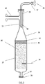
- High-pressure auto-thermal system for reforming alcohol and producing hydrogen contains an auto-thermal reforming unit (1), depicted in Figure 2.
- the Venturi throat smoothly increases the diameter (divergent nozzle) (32) up to the diameter of the envelope (27) so that the enlargement is gradual to avoid swirling near the wall, the angle must be calculated depending on the flow load to avoid such swirls;
- This mixer design provides a good blending, dead volumes and eddies are avoided, and the operating conditions (pressure and temperature) guarantee a self-ignition delay time of few seconds.
- the oxygen mixture is made as close as possible to the catalyst. Therefore, with this design, any problem related with flame combustion produced by the auto-ignition of the mixture before reaching the catalyst is minimized;
- the auto-thermal reforming unit (1) described in Figure 3 comprises the elements described in the auto-thermal reforming unit (1) described in Figure 2 , with the exception of the following modifications.
- the oxygen dosing is done with a lance (39) ( Figure 3 ) in which the Venturi throat itself (33) is created by the area restriction to the flow because of the introduction of the lance (39), achieving similar gas cross velocities to those mentioned above (20-40 m/s).
- the oxygen will be dosed by orifices (38) located in the lower part of the lance (39).
- This lance (39) has no dead volumes in it and can be manufactured from the mechanization of a bar.
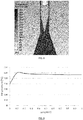
- Figures 6, 7 and 8 show Computations Fluid Dynamics (CFD) simulations of the oxygen mixing, temperature profile and velocity of this mixer with lance. It is observed that a good oxygen mixture is almost immediate, as well as the homogenization of temperature. When reaching the bed of ceramic inert (40) the velocity is equalized ( Figure 8 ), maintaining a homogeneous velocity profile throughout the diameter.
- CFD Fluid Dynamics
- High-pressure auto-thermal system for reforming alcohol and producing hydrogen contains an auto-thermal reforming unit (1), depicted in Figure 4.
- the auto-thermal reforming unit (1) described in Figure 4 comprises the elements described in the auto-thermal reforming unit (1) described in Figure 2 , with the exception of the following modifications.
- the temperature probes (30) used to measure the inner temperature inside the envelope (27) are replaced by a thermowell arranged in vertical position. It allows the use of multi-point temperature sensors distributed along the thermowell, allowing a more easy to construct embodiment.
Priority Applications (2)
| Application Number | Priority Date | Filing Date | Title |
|---|---|---|---|
| EP19382085.9A EP3693338B1 (fr) | 2019-02-07 | 2019-02-07 | Système auto-thermique haute pression pour réformer de l'alcool et produire de l'hydrogène, et procédé correspondant |
| PCT/EP2020/051755 WO2020160935A1 (fr) | 2019-02-07 | 2020-01-24 | Système auto-thermique haute pression pour le reformage d'alcool et la production d'hydrogène, procédé et unités associés |
Applications Claiming Priority (1)
| Application Number | Priority Date | Filing Date | Title |
|---|---|---|---|
| EP19382085.9A EP3693338B1 (fr) | 2019-02-07 | 2019-02-07 | Système auto-thermique haute pression pour réformer de l'alcool et produire de l'hydrogène, et procédé correspondant |
Publications (2)
| Publication Number | Publication Date |
|---|---|
| EP3693338A1 true EP3693338A1 (fr) | 2020-08-12 |
| EP3693338B1 EP3693338B1 (fr) | 2021-09-01 |
Family
ID=65529614
Family Applications (1)
| Application Number | Title | Priority Date | Filing Date |
|---|---|---|---|
| EP19382085.9A Active EP3693338B1 (fr) | 2019-02-07 | 2019-02-07 | Système auto-thermique haute pression pour réformer de l'alcool et produire de l'hydrogène, et procédé correspondant |
Country Status (2)
| Country | Link |
|---|---|
| EP (1) | EP3693338B1 (fr) |
| WO (1) | WO2020160935A1 (fr) |
Cited By (2)
| Publication number | Priority date | Publication date | Assignee | Title |
|---|---|---|---|---|
| CN113883417A (zh) * | 2021-10-08 | 2022-01-04 | 中国海洋石油集团有限公司 | 一种制氢加氢站系统的设备选型方法 |
| CN114408862A (zh) * | 2022-01-26 | 2022-04-29 | 中国科学院生态环境研究中心 | 一种中小型生物乙醇重整制氢的装置系统及重整制氢的方法 |
Citations (19)
| Publication number | Priority date | Publication date | Assignee | Title |
|---|---|---|---|---|
| US3871838A (en) | 1972-07-03 | 1975-03-18 | Siemens Ag | Apparatus for reacting vaporized, gasified or atomized hydrocarbon with a gas serving as an oxygen carrier |
| US4865820A (en) | 1987-08-14 | 1989-09-12 | Davy Mckee Corporation | Gas mixer and distributor for reactor |
| US5048284A (en) * | 1986-05-27 | 1991-09-17 | Imperial Chemical Industries Plc | Method of operating gas turbines with reformed fuel |
| WO2001025140A1 (fr) | 1999-10-05 | 2001-04-12 | Ballard Power Systems Inc. | Systeme de generation d'energie de pile a combustible a reformeur autothermique |
| US20020088179A1 (en) | 2000-01-24 | 2002-07-11 | Lesieur Roger R. | Autothermal fuel gas reformer assemblage |
| US6620389B1 (en) | 2000-06-21 | 2003-09-16 | Utc Fuel Cells, Llc | Fuel gas reformer assemblage |
| US20040175665A1 (en) | 2001-03-30 | 2004-09-09 | Goebel Steven G. | Apparatus for mixing fuel and an oxidant |
| WO2004112954A1 (fr) * | 2003-06-23 | 2004-12-29 | Casale Chemicals S.A. | Appareil de reformage secondaire |
| US20050066577A1 (en) | 2003-08-22 | 2005-03-31 | Syntroleum Corporation | Process for production of synthesis gas using an oxygen-containing gas |
| WO2006065766A2 (fr) | 2004-12-14 | 2006-06-22 | Syntroleum Corporation | Melangeur de reformeur autothermique sans bruleur |
| US20070122667A1 (en) | 2005-11-28 | 2007-05-31 | Kelley Richard H | Fuel cell system with integrated fuel processor |
| EP1808327A1 (fr) | 2006-01-13 | 2007-07-18 | Claudio Rossi | Production d'énergie électrique par des piles à combustible avec de l'hydrogène obtenu par reformage catalytique d'éthanol |
| US20080011250A1 (en) | 2004-11-17 | 2008-01-17 | Zdenek Pors | Mixing Chamber for a Reformer and Method for Operating Same |
| WO2011148068A2 (fr) | 2010-05-25 | 2011-12-01 | IFP Energies Nouvelles | Réacteur pour le reformage autotherme de gasoil |
| WO2011148066A2 (fr) | 2010-05-25 | 2011-12-01 | IFP Energies Nouvelles | Procédé de production anaérobie d'hydrogène |
| EP2525146A2 (fr) | 2011-05-14 | 2012-11-21 | Howaldtswerke-Deutsche Werft GmbH | Procédé de combustion d'un mélange combustible-oxygène et dispositif d'exécution de ce procédé |
| EP2641866A1 (fr) | 2010-11-18 | 2013-09-25 | Técnicas Reunidas, S.A. | Système de traitement d'éthanol intégré à des systèmes de propulsion anaérobie |
| WO2015198186A1 (fr) | 2014-06-23 | 2015-12-30 | Tubitak | Réacteur de reformeur autothermique et système d'alimentation associé |
| EP3441360A1 (fr) * | 2017-08-10 | 2019-02-13 | Sener Ingenieria Y Sistemas, S.A. | Système de reformage d'alcools et de la production d'hydrogène, des unités de système et procédé associé |
-
2019
- 2019-02-07 EP EP19382085.9A patent/EP3693338B1/fr active Active
-
2020
- 2020-01-24 WO PCT/EP2020/051755 patent/WO2020160935A1/fr active Application Filing
Patent Citations (19)
| Publication number | Priority date | Publication date | Assignee | Title |
|---|---|---|---|---|
| US3871838A (en) | 1972-07-03 | 1975-03-18 | Siemens Ag | Apparatus for reacting vaporized, gasified or atomized hydrocarbon with a gas serving as an oxygen carrier |
| US5048284A (en) * | 1986-05-27 | 1991-09-17 | Imperial Chemical Industries Plc | Method of operating gas turbines with reformed fuel |
| US4865820A (en) | 1987-08-14 | 1989-09-12 | Davy Mckee Corporation | Gas mixer and distributor for reactor |
| WO2001025140A1 (fr) | 1999-10-05 | 2001-04-12 | Ballard Power Systems Inc. | Systeme de generation d'energie de pile a combustible a reformeur autothermique |
| US20020088179A1 (en) | 2000-01-24 | 2002-07-11 | Lesieur Roger R. | Autothermal fuel gas reformer assemblage |
| US6620389B1 (en) | 2000-06-21 | 2003-09-16 | Utc Fuel Cells, Llc | Fuel gas reformer assemblage |
| US20040175665A1 (en) | 2001-03-30 | 2004-09-09 | Goebel Steven G. | Apparatus for mixing fuel and an oxidant |
| WO2004112954A1 (fr) * | 2003-06-23 | 2004-12-29 | Casale Chemicals S.A. | Appareil de reformage secondaire |
| US20050066577A1 (en) | 2003-08-22 | 2005-03-31 | Syntroleum Corporation | Process for production of synthesis gas using an oxygen-containing gas |
| US20080011250A1 (en) | 2004-11-17 | 2008-01-17 | Zdenek Pors | Mixing Chamber for a Reformer and Method for Operating Same |
| WO2006065766A2 (fr) | 2004-12-14 | 2006-06-22 | Syntroleum Corporation | Melangeur de reformeur autothermique sans bruleur |
| US20070122667A1 (en) | 2005-11-28 | 2007-05-31 | Kelley Richard H | Fuel cell system with integrated fuel processor |
| EP1808327A1 (fr) | 2006-01-13 | 2007-07-18 | Claudio Rossi | Production d'énergie électrique par des piles à combustible avec de l'hydrogène obtenu par reformage catalytique d'éthanol |
| WO2011148068A2 (fr) | 2010-05-25 | 2011-12-01 | IFP Energies Nouvelles | Réacteur pour le reformage autotherme de gasoil |
| WO2011148066A2 (fr) | 2010-05-25 | 2011-12-01 | IFP Energies Nouvelles | Procédé de production anaérobie d'hydrogène |
| EP2641866A1 (fr) | 2010-11-18 | 2013-09-25 | Técnicas Reunidas, S.A. | Système de traitement d'éthanol intégré à des systèmes de propulsion anaérobie |
| EP2525146A2 (fr) | 2011-05-14 | 2012-11-21 | Howaldtswerke-Deutsche Werft GmbH | Procédé de combustion d'un mélange combustible-oxygène et dispositif d'exécution de ce procédé |
| WO2015198186A1 (fr) | 2014-06-23 | 2015-12-30 | Tubitak | Réacteur de reformeur autothermique et système d'alimentation associé |
| EP3441360A1 (fr) * | 2017-08-10 | 2019-02-13 | Sener Ingenieria Y Sistemas, S.A. | Système de reformage d'alcools et de la production d'hydrogène, des unités de système et procédé associé |
Cited By (3)
| Publication number | Priority date | Publication date | Assignee | Title |
|---|---|---|---|---|
| CN113883417A (zh) * | 2021-10-08 | 2022-01-04 | 中国海洋石油集团有限公司 | 一种制氢加氢站系统的设备选型方法 |
| CN113883417B (zh) * | 2021-10-08 | 2024-04-09 | 中国海洋石油集团有限公司 | 一种制氢加氢站系统的设备选型方法 |
| CN114408862A (zh) * | 2022-01-26 | 2022-04-29 | 中国科学院生态环境研究中心 | 一种中小型生物乙醇重整制氢的装置系统及重整制氢的方法 |
Also Published As
| Publication number | Publication date |
|---|---|
| EP3693338B1 (fr) | 2021-09-01 |
| WO2020160935A1 (fr) | 2020-08-13 |
Similar Documents
| Publication | Publication Date | Title |
|---|---|---|
| US7832364B2 (en) | Heat transfer unit for steam generation and gas preheating | |
| US7578669B2 (en) | Hybrid combustor for fuel processing applications | |
| US6835354B2 (en) | Integrated reactor | |
| JP6002249B2 (ja) | 水素生成のための触媒燃焼式熱統合型改質器 | |
| US8986405B2 (en) | Gas generator and processes for the conversion of a fuel into an oxygen-depleted gas and/or hydrogen-enriched gas | |
| CA2434997C (fr) | Procede et appareil pour la production d'hydrogene | |
| RU2415073C2 (ru) | Компактный реактор реформинга | |
| US20080019902A1 (en) | Process for producing hydrogen | |
| US8444951B2 (en) | Catalytic process and system for converting liquid fuels into syngas | |
| US20030188475A1 (en) | Dynamic fuel processor with controlled declining temperatures | |
| US7517372B2 (en) | Integrated fuel processor subsystem with quasi-autothermal reforming | |
| Nahar et al. | Recent advances in hydrogen production via autothermal reforming process (ATR): a review of patents and research articles | |
| US20080141584A1 (en) | Methods for Using a Catalyst Preburner in Fuel Processing Applications | |
| EP3693338B1 (fr) | Système auto-thermique haute pression pour réformer de l'alcool et produire de l'hydrogène, et procédé correspondant | |
| JP2008214165A (ja) | 可燃ガス混合方法及び混合器 | |
| EP3441360B1 (fr) | Système de reformage d'alcools et de la production d'hydrogène, des unités de système et procédé associé | |
| KR20160045737A (ko) | 탄화수소 및 알코올 개질 시스템 용 버너, 상기 버너를 포함하는 탄화수소 및 알코올 개질 시스템 및 관련 방법 | |
| US8690976B2 (en) | Fuel reformer | |
| KR20160045738A (ko) | 탄화수소 및 알코올 개질 시스템용 다관식 개질기 및 이를 포함하는 탄화수소 및 알코올 개질 시스템, 및 관련 방법 | |
| AU2013206509A1 (en) | Heat transfer unit for steam generation and gas preheating |
Legal Events
| Date | Code | Title | Description |
|---|---|---|---|
| PUAI | Public reference made under article 153(3) epc to a published international application that has entered the european phase |
Free format text: ORIGINAL CODE: 0009012 |
|
| STAA | Information on the status of an ep patent application or granted ep patent |
Free format text: STATUS: THE APPLICATION HAS BEEN PUBLISHED |
|
| AK | Designated contracting states |
Kind code of ref document: A1 Designated state(s): AL AT BE BG CH CY CZ DE DK EE ES FI FR GB GR HR HU IE IS IT LI LT LU LV MC MK MT NL NO PL PT RO RS SE SI SK SM TR |
|
| AX | Request for extension of the european patent |
Extension state: BA ME |
|
| STAA | Information on the status of an ep patent application or granted ep patent |
Free format text: STATUS: REQUEST FOR EXAMINATION WAS MADE |
|
| 17P | Request for examination filed |
Effective date: 20210201 |
|
| RBV | Designated contracting states (corrected) |
Designated state(s): AL AT BE BG CH CY CZ DE DK EE ES FI FR GB GR HR HU IE IS IT LI LT LU LV MC MK MT NL NO PL PT RO RS SE SI SK SM TR |
|
| GRAP | Despatch of communication of intention to grant a patent |
Free format text: ORIGINAL CODE: EPIDOSNIGR1 |
|
| STAA | Information on the status of an ep patent application or granted ep patent |
Free format text: STATUS: GRANT OF PATENT IS INTENDED |
|
| RIC1 | Information provided on ipc code assigned before grant |
Ipc: B01J 8/02 20060101ALI20210303BHEP Ipc: C01B 3/50 20060101ALI20210303BHEP Ipc: C01B 3/32 20060101AFI20210303BHEP Ipc: B01J 4/00 20060101ALI20210303BHEP Ipc: B01J 8/04 20060101ALI20210303BHEP |
|
| INTG | Intention to grant announced |
Effective date: 20210324 |
|
| GRAS | Grant fee paid |
Free format text: ORIGINAL CODE: EPIDOSNIGR3 |
|
| GRAA | (expected) grant |
Free format text: ORIGINAL CODE: 0009210 |
|
| STAA | Information on the status of an ep patent application or granted ep patent |
Free format text: STATUS: THE PATENT HAS BEEN GRANTED |
|
| AK | Designated contracting states |
Kind code of ref document: B1 Designated state(s): AL AT BE BG CH CY CZ DE DK EE ES FI FR GB GR HR HU IE IS IT LI LT LU LV MC MK MT NL NO PL PT RO RS SE SI SK SM TR |
|
| REG | Reference to a national code |
Ref country code: GB Ref legal event code: FG4D |
|
| REG | Reference to a national code |
Ref country code: CH Ref legal event code: EP Ref country code: AT Ref legal event code: REF Ref document number: 1426062 Country of ref document: AT Kind code of ref document: T Effective date: 20210915 |
|
| REG | Reference to a national code |
Ref country code: DE Ref legal event code: R096 Ref document number: 602019007379 Country of ref document: DE |
|
| REG | Reference to a national code |
Ref country code: IE Ref legal event code: FG4D |
|
| REG | Reference to a national code |
Ref country code: LT Ref legal event code: MG9D |
|
| REG | Reference to a national code |
Ref country code: NL Ref legal event code: MP Effective date: 20210901 |
|
| PG25 | Lapsed in a contracting state [announced via postgrant information from national office to epo] |
Ref country code: BG Free format text: LAPSE BECAUSE OF FAILURE TO SUBMIT A TRANSLATION OF THE DESCRIPTION OR TO PAY THE FEE WITHIN THE PRESCRIBED TIME-LIMIT Effective date: 20211201 Ref country code: LT Free format text: LAPSE BECAUSE OF FAILURE TO SUBMIT A TRANSLATION OF THE DESCRIPTION OR TO PAY THE FEE WITHIN THE PRESCRIBED TIME-LIMIT Effective date: 20210901 Ref country code: FI Free format text: LAPSE BECAUSE OF FAILURE TO SUBMIT A TRANSLATION OF THE DESCRIPTION OR TO PAY THE FEE WITHIN THE PRESCRIBED TIME-LIMIT Effective date: 20210901 Ref country code: HR Free format text: LAPSE BECAUSE OF FAILURE TO SUBMIT A TRANSLATION OF THE DESCRIPTION OR TO PAY THE FEE WITHIN THE PRESCRIBED TIME-LIMIT Effective date: 20210901 Ref country code: NO Free format text: LAPSE BECAUSE OF FAILURE TO SUBMIT A TRANSLATION OF THE DESCRIPTION OR TO PAY THE FEE WITHIN THE PRESCRIBED TIME-LIMIT Effective date: 20211201 Ref country code: ES Free format text: LAPSE BECAUSE OF FAILURE TO SUBMIT A TRANSLATION OF THE DESCRIPTION OR TO PAY THE FEE WITHIN THE PRESCRIBED TIME-LIMIT Effective date: 20210901 Ref country code: SE Free format text: LAPSE BECAUSE OF FAILURE TO SUBMIT A TRANSLATION OF THE DESCRIPTION OR TO PAY THE FEE WITHIN THE PRESCRIBED TIME-LIMIT Effective date: 20210901 Ref country code: RS Free format text: LAPSE BECAUSE OF FAILURE TO SUBMIT A TRANSLATION OF THE DESCRIPTION OR TO PAY THE FEE WITHIN THE PRESCRIBED TIME-LIMIT Effective date: 20210901 |
|
| REG | Reference to a national code |
Ref country code: AT Ref legal event code: MK05 Ref document number: 1426062 Country of ref document: AT Kind code of ref document: T Effective date: 20210901 |
|
| PG25 | Lapsed in a contracting state [announced via postgrant information from national office to epo] |
Ref country code: PL Free format text: LAPSE BECAUSE OF FAILURE TO SUBMIT A TRANSLATION OF THE DESCRIPTION OR TO PAY THE FEE WITHIN THE PRESCRIBED TIME-LIMIT Effective date: 20210901 Ref country code: LV Free format text: LAPSE BECAUSE OF FAILURE TO SUBMIT A TRANSLATION OF THE DESCRIPTION OR TO PAY THE FEE WITHIN THE PRESCRIBED TIME-LIMIT Effective date: 20210901 Ref country code: GR Free format text: LAPSE BECAUSE OF FAILURE TO SUBMIT A TRANSLATION OF THE DESCRIPTION OR TO PAY THE FEE WITHIN THE PRESCRIBED TIME-LIMIT Effective date: 20211202 |
|
| PG25 | Lapsed in a contracting state [announced via postgrant information from national office to epo] |
Ref country code: AT Free format text: LAPSE BECAUSE OF FAILURE TO SUBMIT A TRANSLATION OF THE DESCRIPTION OR TO PAY THE FEE WITHIN THE PRESCRIBED TIME-LIMIT Effective date: 20210901 |
|
| PG25 | Lapsed in a contracting state [announced via postgrant information from national office to epo] |
Ref country code: IS Free format text: LAPSE BECAUSE OF FAILURE TO SUBMIT A TRANSLATION OF THE DESCRIPTION OR TO PAY THE FEE WITHIN THE PRESCRIBED TIME-LIMIT Effective date: 20220101 Ref country code: SM Free format text: LAPSE BECAUSE OF FAILURE TO SUBMIT A TRANSLATION OF THE DESCRIPTION OR TO PAY THE FEE WITHIN THE PRESCRIBED TIME-LIMIT Effective date: 20210901 Ref country code: SK Free format text: LAPSE BECAUSE OF FAILURE TO SUBMIT A TRANSLATION OF THE DESCRIPTION OR TO PAY THE FEE WITHIN THE PRESCRIBED TIME-LIMIT Effective date: 20210901 Ref country code: RO Free format text: LAPSE BECAUSE OF FAILURE TO SUBMIT A TRANSLATION OF THE DESCRIPTION OR TO PAY THE FEE WITHIN THE PRESCRIBED TIME-LIMIT Effective date: 20210901 Ref country code: PT Free format text: LAPSE BECAUSE OF FAILURE TO SUBMIT A TRANSLATION OF THE DESCRIPTION OR TO PAY THE FEE WITHIN THE PRESCRIBED TIME-LIMIT Effective date: 20220103 Ref country code: NL Free format text: LAPSE BECAUSE OF FAILURE TO SUBMIT A TRANSLATION OF THE DESCRIPTION OR TO PAY THE FEE WITHIN THE PRESCRIBED TIME-LIMIT Effective date: 20210901 Ref country code: EE Free format text: LAPSE BECAUSE OF FAILURE TO SUBMIT A TRANSLATION OF THE DESCRIPTION OR TO PAY THE FEE WITHIN THE PRESCRIBED TIME-LIMIT Effective date: 20210901 Ref country code: CZ Free format text: LAPSE BECAUSE OF FAILURE TO SUBMIT A TRANSLATION OF THE DESCRIPTION OR TO PAY THE FEE WITHIN THE PRESCRIBED TIME-LIMIT Effective date: 20210901 Ref country code: AL Free format text: LAPSE BECAUSE OF FAILURE TO SUBMIT A TRANSLATION OF THE DESCRIPTION OR TO PAY THE FEE WITHIN THE PRESCRIBED TIME-LIMIT Effective date: 20210901 |
|
| REG | Reference to a national code |
Ref country code: DE Ref legal event code: R097 Ref document number: 602019007379 Country of ref document: DE |
|
| PLBE | No opposition filed within time limit |
Free format text: ORIGINAL CODE: 0009261 |
|
| STAA | Information on the status of an ep patent application or granted ep patent |
Free format text: STATUS: NO OPPOSITION FILED WITHIN TIME LIMIT |
|
| PG25 | Lapsed in a contracting state [announced via postgrant information from national office to epo] |
Ref country code: IT Free format text: LAPSE BECAUSE OF FAILURE TO SUBMIT A TRANSLATION OF THE DESCRIPTION OR TO PAY THE FEE WITHIN THE PRESCRIBED TIME-LIMIT Effective date: 20210901 Ref country code: DK Free format text: LAPSE BECAUSE OF FAILURE TO SUBMIT A TRANSLATION OF THE DESCRIPTION OR TO PAY THE FEE WITHIN THE PRESCRIBED TIME-LIMIT Effective date: 20210901 |
|
| 26N | No opposition filed |
Effective date: 20220602 |
|
| PG25 | Lapsed in a contracting state [announced via postgrant information from national office to epo] |
Ref country code: SI Free format text: LAPSE BECAUSE OF FAILURE TO SUBMIT A TRANSLATION OF THE DESCRIPTION OR TO PAY THE FEE WITHIN THE PRESCRIBED TIME-LIMIT Effective date: 20210901 |
|
| PG25 | Lapsed in a contracting state [announced via postgrant information from national office to epo] |
Ref country code: MC Free format text: LAPSE BECAUSE OF FAILURE TO SUBMIT A TRANSLATION OF THE DESCRIPTION OR TO PAY THE FEE WITHIN THE PRESCRIBED TIME-LIMIT Effective date: 20210901 |
|
| REG | Reference to a national code |
Ref country code: CH Ref legal event code: PL |
|
| PG25 | Lapsed in a contracting state [announced via postgrant information from national office to epo] |
Ref country code: LU Free format text: LAPSE BECAUSE OF NON-PAYMENT OF DUE FEES Effective date: 20220207 |
|
| PG25 | Lapsed in a contracting state [announced via postgrant information from national office to epo] |
Ref country code: LI Free format text: LAPSE BECAUSE OF NON-PAYMENT OF DUE FEES Effective date: 20220228 Ref country code: IE Free format text: LAPSE BECAUSE OF NON-PAYMENT OF DUE FEES Effective date: 20220207 Ref country code: CH Free format text: LAPSE BECAUSE OF NON-PAYMENT OF DUE FEES Effective date: 20220228 |
|
| PGFP | Annual fee paid to national office [announced via postgrant information from national office to epo] |
Ref country code: FR Payment date: 20230208 Year of fee payment: 5 |
|
| PGFP | Annual fee paid to national office [announced via postgrant information from national office to epo] |
Ref country code: DE Payment date: 20230131 Year of fee payment: 5 Ref country code: BE Payment date: 20230216 Year of fee payment: 5 |
|
| GBPC | Gb: european patent ceased through non-payment of renewal fee |
Effective date: 20230207 |
|
| PG25 | Lapsed in a contracting state [announced via postgrant information from national office to epo] |
Ref country code: GB Free format text: LAPSE BECAUSE OF NON-PAYMENT OF DUE FEES Effective date: 20230207 |
|
| PG25 | Lapsed in a contracting state [announced via postgrant information from national office to epo] |
Ref country code: GB Free format text: LAPSE BECAUSE OF NON-PAYMENT OF DUE FEES Effective date: 20230207 |