EP3693319A1 - Escalator with a sensor for detecting sheave misalignment - Google Patents
Escalator with a sensor for detecting sheave misalignment Download PDFInfo
- Publication number
- EP3693319A1 EP3693319A1 EP19196567.2A EP19196567A EP3693319A1 EP 3693319 A1 EP3693319 A1 EP 3693319A1 EP 19196567 A EP19196567 A EP 19196567A EP 3693319 A1 EP3693319 A1 EP 3693319A1
- Authority
- EP
- European Patent Office
- Prior art keywords
- sheave
- belt
- sheaves
- sensor
- alignment
- Prior art date
- Legal status (The legal status is an assumption and is not a legal conclusion. Google has not performed a legal analysis and makes no representation as to the accuracy of the status listed.)
- Granted
Links
Images



Classifications
-
- B—PERFORMING OPERATIONS; TRANSPORTING
- B66—HOISTING; LIFTING; HAULING
- B66B—ELEVATORS; ESCALATORS OR MOVING WALKWAYS
- B66B29/00—Safety devices of escalators or moving walkways
- B66B29/005—Applications of security monitors
-
- B—PERFORMING OPERATIONS; TRANSPORTING
- B66—HOISTING; LIFTING; HAULING
- B66B—ELEVATORS; ESCALATORS OR MOVING WALKWAYS
- B66B25/00—Control of escalators or moving walkways
- B66B25/006—Monitoring for maintenance or repair
-
- B—PERFORMING OPERATIONS; TRANSPORTING
- B66—HOISTING; LIFTING; HAULING
- B66B—ELEVATORS; ESCALATORS OR MOVING WALKWAYS
- B66B23/00—Component parts of escalators or moving walkways
- B66B23/02—Driving gear
- B66B23/04—Driving gear for handrails
-
- B—PERFORMING OPERATIONS; TRANSPORTING
- B66—HOISTING; LIFTING; HAULING
- B66B—ELEVATORS; ESCALATORS OR MOVING WALKWAYS
- B66B29/00—Safety devices of escalators or moving walkways
Definitions
- the embodiments herein relate to escalator maintenance and more specifically to an escalator with a hall-effect sensor and magnet configured to detect sheave misalignment.
- Aligning of an escalator handrail sheave may be a manually intensive and inaccurate process. In addition, aligning the sheave may adversely affect other escalator components, which may have become affected by the misaligned sheave.
- an escalator handrail belt run-out from a drive sheave may be dangerous, and this may also increase noise and vibration of escalator operations, damage the drive system and affect the safety of escalator passengers.
- an escalator system comprising: a first member, a first belt, a first assembly operationally connected to the first member and the first belt, the first assembly comprising a plurality of sheaves mounted proximate the first member for driving the first belt, and a plurality of sensors for the plurality of sheaves, the plurality of sensors having a plurality of sampling elements and sensing elements, the plurality of sampling elements being disposed on the respective plurality of sheaves and the plurality of sensing elements being disposed on the first member proximate the respective plurality of sheaves, a controller communicating with the plurality of sensing elements, wherein when the first belt is moving from rotation of the plurality of sheaves the controller: receives data from the respective plurality of sensors, identifies from the data a first sheave of the plurality of sheaves as comprising a reference alignment value for the system, determines for the plurality of sheaves a respective plurality of alignment values, compares the plurality of alignment values with the reference alignment
- a first predetermined response is transmitting an electronic alert to a building management system (BMS).
- BMS building management system
- a second predetermined response is transmitting an electronic alert to the BMS and stopping the system, wherein the second predetermined amount is greater than the first predetermined amount.
- the plurality of alignment values comprise a respective plurality of parallel alignment values and angular alignment values for the respective plurality of sheaves.
- the plurality of sheaves includes one or more of a main handrail drive sheave, a tensioner for the main drive sheave, a lower idler sheave and an upper idler sheave.
- the first sheave is the main drive sheave.
- the plurality of sensors comprise a respective plurality of hall effect sensors and the plurality of sampling elements are a respective plurality of magnets.
- the plurality of sheaves comprise a respective plurality of hubs, and the plurality of sampling elements are disposed on the respective plurality of hubs.
- the system comprises an escalator brake operationally controlled by the controller.
- the first belt is a handrail belt
- the first assembly is a handrail belt drive assembly
- the first member is a stationary escalator truss.
- an escalator system comprising: a first member, a belt, a handrail drive assembly operationally connected to the first member and the belt, the assembly comprising: a sheave mounted proximate the first member on which the first belt is driven, and a sensor mounted to the first member proximate to the sheave, the sensor sensing a relative transverse position of the belt relative to the sheave, a controller communicating with the sensor, wherein when belt is moving from rotation of the sheave the controller: receives data from the sensor, determines when the belt moves transversely relative to the sheave, compares the transverse movement with a reference value, provides a predetermined response when the transverse movement diverges from the reference value by more than a predetermined amount.
- the predetermined response is transmitting an electronic alert to a building management system (BMS).
- BMS building management system
- the predetermined response is transmitting an electronic alert to the BMS and stopping the system.
- the transverse movement is toward and/or away from the sensor relative to the sheave.
- the sheave is one or more of a main handrail drive sheave, a tensioner for the main drive sheave, a lower idler sheave and an upper idler sheave.
- the sheave is the main drive sheave.
- the senor comprises a proximity sensor.
- the embodiments comprise a plurality of sheaves including the sheave, each including a respective sensor mounted proximate thereto, each sensor communicating with the controller to determine whether the belt is transversely moving relative to any of the plurality of sheaves.
- the embodiments comprise an escalator brake operationally controlled by the controller.
- the first belt is a handrail belt
- the first assembly is a handrail belt drive assembly
- the first member is a stationary escalator truss.
- the system disclosed herein comprises a conveyance system that moves passengers between floors and/or along a single floor.
- conveyance systems may include escalators, people movers, etc.
- the system 200 may comprise a first member 210, which is a first stationary member.
- the system 200 may further comprise a first belt 220, which is a handrail belt, and a first assembly 230, which may be handrail belt drive assembly.
- the first assembly 230 may be operationally connected to the first member 210 and the first belt 220.
- the first assembly 230 may comprise a plurality of sheaves referenced generally as 240, including first sheave 240A.
- the plurality of sheaves 240 may be mounted proximate the first member 210 for driving the first belt 220.
- Accompanying the plurality of sheaves 240 may be a respective plurality of sensors referenced generally as 250, including first sensor 250A.
- the plurality of sensors 250 may have a respective plurality of sampling elements referenced generally as 260 including first sampling element 260A.
- the plurality of sensors 250 may also have a respective plurality of sensing elements referenced generally as 270, including first sensing element 270A.
- the plurality of sampling elements 260 may be respectively disposed on the plurality of sheaves 240.
- the plurality of sensing elements 270 may be disposed on the first member 210, illustrated schematically in FIG. 2 , proximate the respective plurality of sheaves 240.
- a controller 280 illustrated schematically in FIG. 2 , may communicate with the plurality of sensing elements 270.
- Process S200 may include the controller 280 performing step S210 of receiving data from the plurality of sensors 250.
- step S220 may include the controller 280 identifying the first sheave 250A as comprising a reference alignment value for the system 200.
- the controller 280 may also perform step S230 of determining for the plurality of sheaves 240 a respective plurality of alignment values.
- the controller 280 may perform the step of comparing the plurality of alignment values with the reference alignment value.
- Process S200 may further include the controller 280 performing step S250 of providing a predetermined response when any of the plurality of alignment values diverges from the reference alignment value by more than a predetermined amount.
- a first predetermined response may be transmitting an electronic alert.
- the alert may be transmitted to a building management system (BMS) 300, for example, over a network 310.
- BMS building management system
- a second predetermined response may also be transmitting an electronic alert to the BMS 300.
- the second response may include stopping the system 200.
- the second predetermined amount is greater than the first predetermined amount.
- the plurality of alignment values may comprise a respective plurality of parallel alignment values and angular alignment values for the plurality of sheaves 240.
- the system 200 may have a desired parallel alignment when, for example, the plurality of sampling elements 260 maintain a fixed distance from the respective plurality of sensing elements 270.
- the system 200 may have a desired angular alignment when, for example, the plurality of sheaves 240 each have a radially extending axis A that extends in a vertical direction V.
- the plurality of sensors 250 may comprise a respective plurality of hall-effect sensors and the plurality of sampling elements 260 may comprise a respective plurality of magnets.
- the plurality of sheaves 240 may comprise a respective plurality of hubs generally referred to as 320 including first hub 320A.
- the plurality of sampling elements 240 may be disposed on the respective plurality of hubs 320.
- the first sheave 240A may comprise a main handrail drive sheave and the plurality of sheaves 240 may further include a tensioner 240B for the main drive sheave 240A, a lower idler sheave 240C and an upper idler sheave 240D.
- the system 200 may include an escalator brake 330 to effect braking.
- the escalator brake 330 may be actuated by the controller 280.
- the first member 210 may be an escalator truss.
- the embodiments provide a first sensor which may be a hall-effect sensor, may be attached to the escalator truss.
- the first sensor may point to a center of a plurality of escalator components including a plurality of sheaves, such as the handrail main drive sheave and the idler sheave, as well as an idler or tensioner.
- a magnet may be attached to a center of a sheave hub for a plurality of sheaves and the idler or tensioner.
- the first sensor may continuously monitor the parallel and angular alignment of the sheave based on the generated magnetic field.
- the first sensor may continuously transmit data to a first controller, which is an escalator controller inside the escalator.
- Data sent from the main sheave may represent a baseline alignment configuration for the plurality of components.
- the associated coordinates relative to each side of the handrail may be stored in the first controller.
- the first controller may continuously monitor the data sent from each sheave. If a difference observed between the main sheave and the other of the plurality of components is greater than a first threshold the first controller indicates determines there is a misalignment and may notify the building management system (BMS). If the difference is greater than a second threshold the first controller may stop the escalator.
- BMS building management system
- a level of misalignment and associated responsive actions and alerts are configurable for each region in the controller.
- Benefits of the above disclosed embodiments may include reduced manual efforts and downtime, and reduced damage of other drive parts if early detection of misalignment is detected, and relatively better service optimization and service cost reduction.
- the handrail drive assembly 230 may include a second sensor 250B that may be placed at on the first member, which may be the truss 210 (illustrated schematically).
- the second sensor 240B may be proximate a distance from one of the sheaves such as the main drive shave 240A, and thereby being a distance from the belt 220.
- the second sensor 240B may be a different type of sensor than the above sensor 240A or may be a same sensor with additional capabilities of detecting translational movement of the belt 220 relative to the sheave 240A and periodically sending sensed data to controller 280.
- the controller 280 may be configured with preset threshold values that enable the controller 280 to determine when the belt 220 has transversely moved relative to the sheave 240A, and is thus potentially slipping off the sheave 240A.
- the controller 280 may provide warnings and alarms if and when the belt 220 moves transversely relative the drive sheave 240A more than one or more reference values which may be allowed tolerances.
- the alarm signals may be sent to the BMS 330 and the controller 280 may actuate the escalator brake 330 to effect escalator braking if the displacement value raises more than the predetermined limits.
- the plurality of sheaves 240 each include a sensor 250B mounted proximate thereto, each sensor 240B communicating with the controller 280 to determine whether the belt 220 is transversely moving relative to any of the plurality of sheaves 240.
- Each sensor 240B may be disposed on the truss 210 proximate a respective one of the plurality of sheaves 240 similarly as provided in FIG. 1 . This configuration may minimize or prevent damage to the handrail drive assembly 230 due to slippage of the belt 220.
- Process S200 may further include the controller 280 performing step S260 of receiving data from the second sensor 252, wherein the data is indicative of the transverse position of the belt 220 relative to the sheave 240A.
- step S270 may include the controller 280 providing a predetermined response when the position of the belt 220 moves transversely relative to the sheave 240A more than one or more reference tolerances, and the predetermined response may include effecting elevator braking and notifying the BMS 330.
- handrail run may be detected during operation and the escalator may be stopped to prevent or minimized system damage. This may reduce service down time and cost if failure by providing early response to potential malfunctions. This may minimize or prevent handrail wear and tear and increase the useful life of the handrail 220.
- embodiments using a controller can be in the form of processor-implemented processes and devices for practicing those processes, such as a processor.
- Embodiments can also be in the form of computer program code containing instructions embodied in tangible media, such as network cloud storage, SD cards, flash drives, floppy diskettes, CD ROMs, hard drives, or any other computer-readable storage medium, wherein, when the computer program code is loaded into and executed by a computer, the computer becomes a device for practicing the embodiments.
- Embodiments can also be in the form of computer program code, for example, whether stored in a storage medium, loaded into and/or executed by a computer, or transmitted over some transmission medium, loaded into and/or executed by a computer, or transmitted over some transmission medium, such as over electrical wiring or cabling, through fiber optics, or via electromagnetic radiation, wherein, when the computer program code is loaded into an executed by a computer, the computer becomes an device for practicing the embodiments.
- the computer program code segments configure the microprocessor to create specific logic circuits.
Landscapes
- Escalators And Moving Walkways (AREA)
Abstract
Description
- The embodiments herein relate to escalator maintenance and more specifically to an escalator with a hall-effect sensor and magnet configured to detect sheave misalignment.
- Aligning of an escalator handrail sheave may be a manually intensive and inaccurate process. In addition, aligning the sheave may adversely affect other escalator components, which may have become affected by the misaligned sheave.
- In addition or as an alternative, an escalator handrail belt run-out from a drive sheave may be dangerous, and this may also increase noise and vibration of escalator operations, damage the drive system and affect the safety of escalator passengers.
- According to a first set of embodiments, disclosed is an escalator system comprising: a first member, a first belt, a first assembly operationally connected to the first member and the first belt, the first assembly comprising a plurality of sheaves mounted proximate the first member for driving the first belt, and a plurality of sensors for the plurality of sheaves, the plurality of sensors having a plurality of sampling elements and sensing elements, the plurality of sampling elements being disposed on the respective plurality of sheaves and the plurality of sensing elements being disposed on the first member proximate the respective plurality of sheaves, a controller communicating with the plurality of sensing elements, wherein when the first belt is moving from rotation of the plurality of sheaves the controller: receives data from the respective plurality of sensors, identifies from the data a first sheave of the plurality of sheaves as comprising a reference alignment value for the system, determines for the plurality of sheaves a respective plurality of alignment values, compares the plurality of alignment values with the reference alignment value, and provides a predetermined response when any of the plurality of alignment values diverges from the reference alignment value by more than a predetermined amount.
- In addition to one or more of the above disclosed features for the first set of embodiments or as an alternate any of the plurality of alignment values diverges from the reference alignment by more than a first predetermined amount, a first predetermined response is transmitting an electronic alert to a building management system (BMS).
- In addition to one or more of the above disclosed features for the first set of embodiments or as an alternate when any of the plurality of alignment values diverges from the reference alignment by more than a second predetermined amount, a second predetermined response is transmitting an electronic alert to the BMS and stopping the system, wherein the second predetermined amount is greater than the first predetermined amount.
- In addition to one or more of the above disclosed features for the first set of embodiments or as an alternate the plurality of alignment values comprise a respective plurality of parallel alignment values and angular alignment values for the respective plurality of sheaves.
- In addition to one or more of the above disclosed features for the first set of embodiments or as an alternate the plurality of sheaves includes one or more of a main handrail drive sheave, a tensioner for the main drive sheave, a lower idler sheave and an upper idler sheave.
- In addition to one or more of the above disclosed features or as an alternate the first sheave is the main drive sheave.
- In addition to one or more of the above disclosed features for the first set of embodiments or as an alternate the plurality of sensors comprise a respective plurality of hall effect sensors and the plurality of sampling elements are a respective plurality of magnets.
- In addition to one or more of the above disclosed features for the first set of embodiments or as an alternate the plurality of sheaves comprise a respective plurality of hubs, and the plurality of sampling elements are disposed on the respective plurality of hubs.
- In addition to one or more of the above disclosed features for the first set of embodiments or as an alternate the system comprises an escalator brake operationally controlled by the controller.
- In addition to one or more of the above disclosed features for the first set of embodiments or as an alternate the first belt is a handrail belt, the first assembly is a handrail belt drive assembly, and the first member is a stationary escalator truss.
- Further disclosed is a method of monitoring an operation of a first assembly of an escalator system, the system including one or more of the above disclosed features for the first set of embodiments.
- According to a second set of embodiments, disclosed is an escalator system comprising: a first member, a belt, a handrail drive assembly operationally connected to the first member and the belt, the assembly comprising: a sheave mounted proximate the first member on which the first belt is driven, and a sensor mounted to the first member proximate to the sheave, the sensor sensing a relative transverse position of the belt relative to the sheave, a controller communicating with the sensor, wherein when belt is moving from rotation of the sheave the controller: receives data from the sensor, determines when the belt moves transversely relative to the sheave, compares the transverse movement with a reference value, provides a predetermined response when the transverse movement diverges from the reference value by more than a predetermined amount.
- In addition to one or more of the above disclosed features for the second set of embodiments or as an alternate when the transverse movement value diverges from the reference value by more than the predetermined amount, the predetermined response is transmitting an electronic alert to a building management system (BMS).
- In addition to one or more of the above disclosed features for the second set of embodiments or as an alternate when the transverse movement values diverges from the reference value by more than the predetermined amount, the predetermined response is transmitting an electronic alert to the BMS and stopping the system.
- In addition to one or more of the above disclosed features for the second set of embodiments or as an alternate the transverse movement is toward and/or away from the sensor relative to the sheave.
- In addition to one or more of the above disclosed features for the second set of embodiments or as an alternate the sheave is one or more of a main handrail drive sheave, a tensioner for the main drive sheave, a lower idler sheave and an upper idler sheave.
- In addition to one or more of the above disclosed features for the second set of embodiments or as an alternate the sheave is the main drive sheave.
- In addition to one or more of the above disclosed features for the second set of embodiments or as an alternate the sensor comprises a proximity sensor.
- In addition to one or more of the above disclosed features for the second set of embodiments or as an alternate the embodiments comprise a plurality of sheaves including the sheave, each including a respective sensor mounted proximate thereto, each sensor communicating with the controller to determine whether the belt is transversely moving relative to any of the plurality of sheaves.
- In addition to one or more of the above disclosed features for the second set of embodiments or as an alternate the embodiments comprise an escalator brake operationally controlled by the controller.
- In addition to one or more of the above disclosed features for the second set of embodiments or as an alternate the first belt is a handrail belt, the first assembly is a handrail belt drive assembly, and the first member is a stationary escalator truss.
- Further disclosed is method of monitoring an operation of a first assembly of an escalator system, the escalator system comprising one or more features disclosed for the second set of embodiments.
- The foregoing features and elements may be combined in various combinations without exclusivity, unless expressly indicated otherwise. These features and elements as well as the operation thereof will become more apparent in light of the following description and the accompanying drawings. It should be understood, however, that the following description and drawings are intended to be illustrative and explanatory in nature and non-limiting.
- The present disclosure is illustrated by way of example and not limited in the accompanying figures in which like reference numerals indicate similar elements.
-
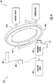
FIG. 1 is a schematic illustration of an escalator system that may employ various embodiments of the present disclosure; -
FIG. 2 is a schematic illustration of additional features of an escalator system that may employ various embodiments of the present disclosure; -
FIG. 3 illustrates a process for utilizing features of a disclosed embodiment; -
FIG. 4 is a schematic illustration of yet additional features of an escalator system that may employ various embodiments of the present disclosure; and -
FIG. 5 illustrates an additional process for utilizing features of a disclosed embodiment. - The system disclosed herein comprises a conveyance system that moves passengers between floors and/or along a single floor. Such conveyance systems may include escalators, people movers, etc.
- Turning to
FIG. 1 , disclosed is anescalator system 200. Thesystem 200 may comprise afirst member 210, which is a first stationary member. Thesystem 200 may further comprise afirst belt 220, which is a handrail belt, and afirst assembly 230, which may be handrail belt drive assembly. Thefirst assembly 230 may be operationally connected to thefirst member 210 and thefirst belt 220. Thefirst assembly 230 may comprise a plurality of sheaves referenced generally as 240, includingfirst sheave 240A. The plurality ofsheaves 240 may be mounted proximate thefirst member 210 for driving thefirst belt 220. Accompanying the plurality ofsheaves 240 may be a respective plurality of sensors referenced generally as 250, includingfirst sensor 250A. - Turning to
FIG. 2 , the plurality ofsensors 250 may have a respective plurality of sampling elements referenced generally as 260 includingfirst sampling element 260A. The plurality ofsensors 250 may also have a respective plurality of sensing elements referenced generally as 270, includingfirst sensing element 270A. The plurality ofsampling elements 260 may be respectively disposed on the plurality ofsheaves 240. The plurality ofsensing elements 270 may be disposed on thefirst member 210, illustrated schematically inFIG. 2 , proximate the respective plurality ofsheaves 240. Acontroller 280, illustrated schematically inFIG. 2 , may communicate with the plurality ofsensing elements 270. - Turning to
FIG. 3 , when thefirst belt 220 is moving from rotation of the plurality ofsheaves 240 thecontroller 280 may perform a process S200 of monitoring alignment status of thesystem 200. Process S200 may include thecontroller 280 performing step S210 of receiving data from the plurality ofsensors 250. In addition step S220 may include thecontroller 280 identifying thefirst sheave 250A as comprising a reference alignment value for thesystem 200. Under process S200 thecontroller 280 may also perform step S230 of determining for the plurality of sheaves 240 a respective plurality of alignment values. Further under step S240 thecontroller 280 may perform the step of comparing the plurality of alignment values with the reference alignment value. Process S200 may further include thecontroller 280 performing step S250 of providing a predetermined response when any of the plurality of alignment values diverges from the reference alignment value by more than a predetermined amount. - Turning back to
FIG. 2 , when any of the plurality of alignment values diverges from the reference alignment value by more than a first predetermined amount, a first predetermined response may be transmitting an electronic alert. The alert may be transmitted to a building management system (BMS) 300, for example, over anetwork 310. According to another embodiment when any of the plurality of alignment values diverges from the reference alignment value by more than a second predetermined amount, a second predetermined response may also be transmitting an electronic alert to theBMS 300. In addition, the second response may include stopping thesystem 200. The second predetermined amount is greater than the first predetermined amount. - According to an embodiment the plurality of alignment values may comprise a respective plurality of parallel alignment values and angular alignment values for the plurality of
sheaves 240. Thesystem 200 may have a desired parallel alignment when, for example, the plurality ofsampling elements 260 maintain a fixed distance from the respective plurality ofsensing elements 270. Thesystem 200 may have a desired angular alignment when, for example, the plurality ofsheaves 240 each have a radially extending axis A that extends in a vertical direction V. - The plurality of
sensors 250 may comprise a respective plurality of hall-effect sensors and the plurality ofsampling elements 260 may comprise a respective plurality of magnets. The plurality ofsheaves 240 may comprise a respective plurality of hubs generally referred to as 320 includingfirst hub 320A. The plurality ofsampling elements 240 may be disposed on the respective plurality ofhubs 320. - Turning back to
FIG. 1 , other features of thesystem 200 are illustrated according to one or more embodiments. Thefirst sheave 240A may comprise a main handrail drive sheave and the plurality ofsheaves 240 may further include atensioner 240B for themain drive sheave 240A, alower idler sheave 240C and anupper idler sheave 240D. Thesystem 200 may include anescalator brake 330 to effect braking. Theescalator brake 330 may be actuated by thecontroller 280. Thefirst member 210 may be an escalator truss. - As disclosed above, the embodiments provide a first sensor which may be a hall-effect sensor, may be attached to the escalator truss. The first sensor may point to a center of a plurality of escalator components including a plurality of sheaves, such as the handrail main drive sheave and the idler sheave, as well as an idler or tensioner. A magnet may be attached to a center of a sheave hub for a plurality of sheaves and the idler or tensioner. The first sensor may continuously monitor the parallel and angular alignment of the sheave based on the generated magnetic field.
- As indicated the first sensor may continuously transmit data to a first controller, which is an escalator controller inside the escalator. Data sent from the main sheave may represent a baseline alignment configuration for the plurality of components. The associated coordinates relative to each side of the handrail may be stored in the first controller. The first controller may continuously monitor the data sent from each sheave. If a difference observed between the main sheave and the other of the plurality of components is greater than a first threshold the first controller indicates determines there is a misalignment and may notify the building management system (BMS). If the difference is greater than a second threshold the first controller may stop the escalator. A level of misalignment and associated responsive actions and alerts are configurable for each region in the controller.
- Benefits of the above disclosed embodiments may include reduced manual efforts and downtime, and reduced damage of other drive parts if early detection of misalignment is detected, and relatively better service optimization and service cost reduction.
- In addition or as an alternative to the above disclosed solutions, turning now to
FIG. 4 , another configuration of theescalator system 200 is illustrated. Within thesystem 200, thehandrail drive assembly 230 may include a second sensor 250B that may be placed at on the first member, which may be the truss 210 (illustrated schematically). Thesecond sensor 240B may be proximate a distance from one of the sheaves such as the main drive shave 240A, and thereby being a distance from thebelt 220. Thesecond sensor 240B may be a different type of sensor than theabove sensor 240A or may be a same sensor with additional capabilities of detecting translational movement of thebelt 220 relative to thesheave 240A and periodically sending sensed data tocontroller 280. - The
controller 280 may be configured with preset threshold values that enable thecontroller 280 to determine when thebelt 220 has transversely moved relative to thesheave 240A, and is thus potentially slipping off thesheave 240A. Thecontroller 280 may provide warnings and alarms if and when thebelt 220 moves transversely relative thedrive sheave 240A more than one or more reference values which may be allowed tolerances. The alarm signals may be sent to theBMS 330 and thecontroller 280 may actuate theescalator brake 330 to effect escalator braking if the displacement value raises more than the predetermined limits. - In one embodiment the plurality of
sheaves 240 each include a sensor 250B mounted proximate thereto, eachsensor 240B communicating with thecontroller 280 to determine whether thebelt 220 is transversely moving relative to any of the plurality ofsheaves 240. Eachsensor 240B may be disposed on thetruss 210 proximate a respective one of the plurality ofsheaves 240 similarly as provided inFIG. 1 . This configuration may minimize or prevent damage to thehandrail drive assembly 230 due to slippage of thebelt 220. - Turning to
FIG. 5 , when thefirst belt 220 is moving actuation of thehandrail drive assembly 230, such as from rotation of the plurality ofsheaves 240, thecontroller 280 may perform the process S200 of monitoring status of thesystem 200, as indicated above. Process S200 may further include thecontroller 280 performing step S260 of receiving data from the second sensor 252, wherein the data is indicative of the transverse position of thebelt 220 relative to thesheave 240A. In addition step S270 may include thecontroller 280 providing a predetermined response when the position of thebelt 220 moves transversely relative to thesheave 240A more than one or more reference tolerances, and the predetermined response may include effecting elevator braking and notifying theBMS 330. - With the above disclosed embodiments handrail run may be detected during operation and the escalator may be stopped to prevent or minimized system damage. This may reduce service down time and cost if failure by providing early response to potential malfunctions. This may minimize or prevent handrail wear and tear and increase the useful life of the
handrail 220. - As described above, embodiments using a controller can be in the form of processor-implemented processes and devices for practicing those processes, such as a processor. Embodiments can also be in the form of computer program code containing instructions embodied in tangible media, such as network cloud storage, SD cards, flash drives, floppy diskettes, CD ROMs, hard drives, or any other computer-readable storage medium, wherein, when the computer program code is loaded into and executed by a computer, the computer becomes a device for practicing the embodiments. Embodiments can also be in the form of computer program code, for example, whether stored in a storage medium, loaded into and/or executed by a computer, or transmitted over some transmission medium, loaded into and/or executed by a computer, or transmitted over some transmission medium, such as over electrical wiring or cabling, through fiber optics, or via electromagnetic radiation, wherein, when the computer program code is loaded into an executed by a computer, the computer becomes an device for practicing the embodiments. When implemented on a general-purpose microprocessor, the computer program code segments configure the microprocessor to create specific logic circuits.
- The term "about" is intended to include the degree of error associated with measurement of the particular quantity and/or manufacturing tolerances based upon the equipment available at the time of filing the application.
- The terminology used herein is for the purpose of describing particular embodiments only and is not intended to be limiting of the present disclosure. As used herein, the singular forms "a", "an" and "the" are intended to include the plural forms as well, unless the context clearly indicates otherwise. It will be further understood that the terms "comprises" and/or "comprising," when used in this specification, specify the presence of stated features, integers, steps, operations, elements, and/or components, but do not preclude the presence or addition of one or more other features, integers, steps, operations, element components, and/or groups thereof.
- Those of skill in the art will appreciate that various example embodiments are shown and described herein, each having certain features in the particular embodiments, but the present disclosure is not thus limited. Rather, the present disclosure can be modified to incorporate any number of variations, alterations, substitutions, combinations, sub-combinations, or equivalent arrangements not heretofore described, but which are commensurate with the scope of the present disclosure. Additionally, while various embodiments of the present disclosure have been described, it is to be understood that aspects of the present disclosure may include only some of the described embodiments. Accordingly, the present disclosure is not to be seen as limited by the foregoing description, but is only limited by the scope of the appended claims.
Claims (15)
- An escalator system comprising:a first member,a first belt,a first assembly operationally connected to the first member and the first belt, the first assembly comprising
a plurality of sheaves mounted proximate the first member for driving the first belt, and a plurality of sensors for the plurality of sheaves,
the plurality of sensors having a plurality of sampling elements and sensing elements, the plurality of sampling elements being disposed on the respective plurality of sheaves and the plurality of sensing elements being disposed on the first member proximate the respective plurality of sheaves,
a controller communicating with the plurality of sensing elements, wherein when the first belt is moving from rotation of the plurality of sheaves wherein the controller is configured to:receive data from the respective plurality of sensors,identifie from the data a first sheave of the plurality of sheaves as comprising a reference alignment value for the system,determine for the plurality of sheaves a respective plurality of alignment values,compare the plurality of alignment values with the reference alignment value, andprovide a predetermined response when any of the plurality of alignment values diverges from the reference alignment value by more than a predetermined amount. - The system of claim 1, wherein when any of the plurality of alignment values diverges from the reference alignment by more than a first predetermined amount, a first predetermined response is transmitting an electronic alert to a building management system (BMS).
- The system of claim 1 or 2, wherein when any of the plurality of alignment values diverges from the reference alignment by more than a second predetermined amount, a second predetermined response is transmitting an electronic alert to the BMS and stopping the system, wherein the second predetermined amount is greater than the first predetermined amount.
- The system of any of the preceding claims, wherein the plurality of alignment values comprise a respective plurality of parallel alignment values and angular alignment values for the respective plurality of sheaves.
- The system of any of the preceding claims, wherein the plurality of sheaves includes one or more of a main handrail drive sheave, a tensioner for the main drive sheave, a lower idler sheave and an upper idler sheave.
- The system of any of the preceding claims,wherein the first sheave is the main drive sheave,
and/orwherein the plurality of sensors comprise a respective plurality of hall effect sensors and the plurality of sampling elements are a respective plurality of magnets. - The system of any of the preceding claims, wherein the plurality of sheaves comprise a respective plurality of hubs, and the plurality of sampling elements are disposed on the respective plurality of hubs.
- An escalator system comprising:a first member,a belt,a handrail drive assembly operationally connected to the first member and the belt, the assembly comprising:a sheave mounted proximate the first member on which the first belt is driven,a sensor mounted to the first member proximate to the sheave, the sensor sensing a relative transverse position of the belt relative to the sheave, anda controller communicating with the sensor,wherein when belt is moving from rotation of the sheave,wherein the controller is configured to:receive data from the sensor,determine when the belt moves transversely relative to the sheave,compare the transverse movement with a reference value,provide a predetermined response when the transverse movement diverges from the reference value by more than a predetermined amount.
- The system of claim 8, wherein when the transverse movement value diverges from the reference value by more than the predetermined amount, the predetermined response is transmitting an electronic alert to a building management system (BMS) and/or wherein when the transverse movement values diverges from the reference value by more than the predetermined amount, the predetermined response is transmitting an electronic alert to the BMS and stopping the system.
- The system of claim 8 or 9, wherein the transverse movement is toward and/or away from the sensor relative to the sheave.
- The system of any of claims 8 to 10, wherein the sheave is one or more of a main handrail drive sheave, a tensioner for the main drive sheave, a lower idler sheave and an upper idler sheave.
- The system of any of claims 8 to 11 wherein the sheave is the main drive sheave, and/or
wherein the sensor comprises a proximity sensor. - The system of any of claims 8 to 12, comprising a plurality of sheaves including the sheave, each including a respective sensor mounted proximate thereto, each sensor communicating with the controller to determine whether the belt is transversely moving relative to any of the plurality of sheaves.
- The system of any of claims 1 to 7, or the system of claims 8 to 13, comprising an escalator brake operationally controlled by the controller.
- The system of any of claims 1 to 7, or the system of claims 8 to 14, wherein the first belt is a handrail belt, the first assembly is a handrail belt drive assembly, and the first member is a stationary escalator truss.
Applications Claiming Priority (1)
| Application Number | Priority Date | Filing Date | Title |
|---|---|---|---|
| IN201811034443 | 2018-09-12 |
Publications (2)
| Publication Number | Publication Date |
|---|---|
| EP3693319A1 true EP3693319A1 (en) | 2020-08-12 |
| EP3693319B1 EP3693319B1 (en) | 2023-06-28 |
Family
ID=67928644
Family Applications (1)
| Application Number | Title | Priority Date | Filing Date |
|---|---|---|---|
| EP19196567.2A Active EP3693319B1 (en) | 2018-09-12 | 2019-09-10 | Escalator with a sensor for detecting sheave misalignment |
Country Status (3)
| Country | Link |
|---|---|
| US (1) | US10850948B2 (en) |
| EP (1) | EP3693319B1 (en) |
| CN (1) | CN110894043B (en) |
Families Citing this family (3)
| Publication number | Priority date | Publication date | Assignee | Title |
|---|---|---|---|---|
| EP3835249A1 (en) * | 2019-12-11 | 2021-06-16 | Otis Elevator Company | Alignment measurement of components of passenger conveyance system |
| US20210403284A1 (en) * | 2020-06-27 | 2021-12-30 | Otis Elevator Company | Sensor orientation indicator for condition based maintenance (cbm) sensing |
| CN113233305A (en) * | 2021-04-09 | 2021-08-10 | 华南理工大学 | Anti-pinch safety device for side surface of escalator and safety detection method thereof |
Citations (3)
| Publication number | Priority date | Publication date | Assignee | Title |
|---|---|---|---|---|
| US5645156A (en) * | 1993-09-01 | 1997-07-08 | Otis Elevator Company | Device for monitoring escalator handrail speed |
| US20030199349A1 (en) * | 2002-04-17 | 2003-10-23 | Sands Jeffrey L. | Lateral sensor for conveyor belt |
| US20170057788A1 (en) * | 2015-08-31 | 2017-03-02 | Kone Corporation | Method, arrangement and elevator |
Family Cites Families (24)
| Publication number | Priority date | Publication date | Assignee | Title |
|---|---|---|---|---|
| US3049213A (en) | 1960-04-22 | 1962-08-14 | Otis Elevator Co | Moving stairway |
| US3568813A (en) | 1969-08-15 | 1971-03-09 | Montgomery Elevator Co | Escalator structure |
| US3926296A (en) | 1973-12-07 | 1975-12-16 | Westmont Ind | Passenger conveyor system |
| JP2522089Y2 (en) | 1990-11-29 | 1997-01-08 | 有限会社ノッコン | A set of named clips |
| JPH09272687A (en) | 1996-04-02 | 1997-10-21 | Central Japan Railway Co | Escalator handrail belt slippage monitoring system |
| DE19617519A1 (en) | 1996-05-02 | 1997-11-06 | O & K Rolltreppen Gmbh | Adjusting system for drive-guide system for person conveying unit e.g. elevator |
| US5782333A (en) * | 1996-12-30 | 1998-07-21 | Otis Elevator Company | Escalator having handrail/drive-wheel self-adjusting traction mechanism |
| WO2002096788A1 (en) | 2001-05-31 | 2002-12-05 | Inventio Ag | Device for determining the position of a rail-guided elevator car with a code support |
| JP2003004486A (en) | 2001-06-21 | 2003-01-08 | Nissan Motor Co Ltd | Rotation angle detector |
| GB2400090B (en) | 2003-04-05 | 2006-04-19 | Renold Plc | Chain wear monitoring method and apparatus |
| US20070000753A1 (en) | 2003-10-29 | 2007-01-04 | Markus Hame | Passenger conveyor drive monitoring arrangement with brake actuation |
| US7404477B1 (en) * | 2004-02-26 | 2008-07-29 | Toennisson H Eugene | Proximity hand rail monitor for a moving walkway |
| EP1796996B1 (en) * | 2004-08-19 | 2013-01-23 | Otis Elevator Company | Method for testing the positional adjustment of a sensor for a people conveyor and a sensor arrangement therefor |
| DE102008009458A1 (en) | 2008-02-15 | 2009-08-20 | Kone Corp. | Escalator or moving walkway |
| WO2010123489A1 (en) | 2009-04-20 | 2010-10-28 | Otis Elevator Company | Automatic adjustment of parameters for safety device |
| JP5717655B2 (en) | 2009-06-26 | 2015-05-13 | 三菱電機株式会社 | Detection device and control device for elevator or escalator |
| CN102398844B (en) | 2011-11-28 | 2013-10-09 | 江南嘉捷电梯股份有限公司 | Device for detecting fall-off of hand strap of escalator or moving sidewalk |
| ITMI20120120A1 (en) | 2012-01-31 | 2013-08-01 | Rexnord Marbett Srl | MONITORING SYSTEM FOR MEASURING SPEED AND LENGTHENING OF TRANSPORT CHAINS OF TRANSPORT OF ITEMS |
| ES2452815B1 (en) | 2013-09-23 | 2015-01-12 | Thyssenkrupp Elevator Innovation Center, S. A. | Railing system for corridors and escalators |
| DE202015001558U1 (en) | 2015-02-26 | 2015-08-20 | Thyssenkrupp Ag | Passenger conveying device with a circulating conveyor belt and with an operating parameter determining unit |
| JP2017171485A (en) | 2016-03-25 | 2017-09-28 | 株式会社日立ビルシステム | Moving handrail deterioration diagnosis device, moving handrail deterioration diagnosis method, and position identification mark used in these |
| CN107662871B (en) * | 2016-07-29 | 2021-04-06 | 奥的斯电梯公司 | Moving handrail monitoring system for passenger transportation device, passenger transportation device and monitoring method thereof |
| US10302549B2 (en) * | 2016-12-07 | 2019-05-28 | Otis Elevator Company | Handrail friction checking device |
| EP3599212B1 (en) * | 2018-07-27 | 2024-06-12 | Otis Elevator Company | Drive misalignment monitoring in a people conveyor |
-
2019
- 2019-08-29 US US16/555,523 patent/US10850948B2/en active Active
- 2019-09-10 EP EP19196567.2A patent/EP3693319B1/en active Active
- 2019-09-11 CN CN201910857248.2A patent/CN110894043B/en active Active
Patent Citations (3)
| Publication number | Priority date | Publication date | Assignee | Title |
|---|---|---|---|---|
| US5645156A (en) * | 1993-09-01 | 1997-07-08 | Otis Elevator Company | Device for monitoring escalator handrail speed |
| US20030199349A1 (en) * | 2002-04-17 | 2003-10-23 | Sands Jeffrey L. | Lateral sensor for conveyor belt |
| US20170057788A1 (en) * | 2015-08-31 | 2017-03-02 | Kone Corporation | Method, arrangement and elevator |
Also Published As
| Publication number | Publication date |
|---|---|
| CN110894043B (en) | 2021-10-08 |
| US10850948B2 (en) | 2020-12-01 |
| EP3693319B1 (en) | 2023-06-28 |
| CN110894043A (en) | 2020-03-20 |
| US20200079623A1 (en) | 2020-03-12 |
Similar Documents
| Publication | Publication Date | Title |
|---|---|---|
| EP1464919B1 (en) | Chain wear monitoring method and apparatus | |
| EP3693319B1 (en) | Escalator with a sensor for detecting sheave misalignment | |
| JP4468224B2 (en) | Elevator position detection system and method | |
| CN102530671B (en) | Elevator system | |
| CN104718148B (en) | The safety device of lift facility | |
| EP3371086B1 (en) | Elevator system and method for controlling an elevator system | |
| US20160145074A1 (en) | Method for controlling an elevator and elevator | |
| JP6324325B2 (en) | Elevator car monitoring device and monitoring method | |
| US20170355560A1 (en) | System and method for monitoring elevator brake capability | |
| US9868615B2 (en) | Method and system for detecting a stall condition in an elevator | |
| HK1201248A1 (en) | Method and arrangement for monitoring the operating condition of a transport system | |
| CN110963385A (en) | Motor operation monitoring method and device for traction drive elevator | |
| CN113213289A (en) | Monitoring device for elevator compensation rope | |
| CN111320047B (en) | Safety system based on well entry detection | |
| CN108840191B (en) | Deviation monitoring device | |
| JP2007230731A (en) | Abnormality detection device of elevator | |
| EP3640185B1 (en) | Water detection inside elevator pit | |
| EP3828115B1 (en) | Emergency stop system for elevator | |
| EP3560873B1 (en) | Prognostic failure detection of elevator roller guide wheel | |
| EP4497717A1 (en) | Brake system for conveyor system, and detection method and controller for brake for conveyor system | |
| CN109476450B (en) | elevator control device | |
| CN105712154B (en) | A kind of novel elevator falling guard equipment | |
| KR100932582B1 (en) | Elevator device | |
| CN120397857A (en) | Method and device for detecting jamming of anti-ropes pulley bearing | |
| CN120191809A (en) | System and method for predicting maintenance needs for at least one component |
Legal Events
| Date | Code | Title | Description |
|---|---|---|---|
| PUAI | Public reference made under article 153(3) epc to a published international application that has entered the european phase |
Free format text: ORIGINAL CODE: 0009012 |
|
| STAA | Information on the status of an ep patent application or granted ep patent |
Free format text: STATUS: THE APPLICATION HAS BEEN PUBLISHED |
|
| AK | Designated contracting states |
Kind code of ref document: A1 Designated state(s): AL AT BE BG CH CY CZ DE DK EE ES FI FR GB GR HR HU IE IS IT LI LT LU LV MC MK MT NL NO PL PT RO RS SE SI SK SM TR |
|
| AX | Request for extension of the european patent |
Extension state: BA ME |
|
| STAA | Information on the status of an ep patent application or granted ep patent |
Free format text: STATUS: REQUEST FOR EXAMINATION WAS MADE |
|
| 17P | Request for examination filed |
Effective date: 20210212 |
|
| RBV | Designated contracting states (corrected) |
Designated state(s): AL AT BE BG CH CY CZ DE DK EE ES FI FR GB GR HR HU IE IS IT LI LT LU LV MC MK MT NL NO PL PT RO RS SE SI SK SM TR |
|
| GRAP | Despatch of communication of intention to grant a patent |
Free format text: ORIGINAL CODE: EPIDOSNIGR1 |
|
| STAA | Information on the status of an ep patent application or granted ep patent |
Free format text: STATUS: GRANT OF PATENT IS INTENDED |
|
| INTG | Intention to grant announced |
Effective date: 20230125 |
|
| GRAS | Grant fee paid |
Free format text: ORIGINAL CODE: EPIDOSNIGR3 |
|
| GRAA | (expected) grant |
Free format text: ORIGINAL CODE: 0009210 |
|
| STAA | Information on the status of an ep patent application or granted ep patent |
Free format text: STATUS: THE PATENT HAS BEEN GRANTED |
|
| AK | Designated contracting states |
Kind code of ref document: B1 Designated state(s): AL AT BE BG CH CY CZ DE DK EE ES FI FR GB GR HR HU IE IS IT LI LT LU LV MC MK MT NL NO PL PT RO RS SE SI SK SM TR |
|
| REG | Reference to a national code |
Ref country code: CH Ref legal event code: EP |
|
| REG | Reference to a national code |
Ref country code: AT Ref legal event code: REF Ref document number: 1582560 Country of ref document: AT Kind code of ref document: T Effective date: 20230715 |
|
| REG | Reference to a national code |
Ref country code: IE Ref legal event code: FG4D |
|
| REG | Reference to a national code |
Ref country code: DE Ref legal event code: R096 Ref document number: 602019031605 Country of ref document: DE |
|
| REG | Reference to a national code |
Ref country code: LT Ref legal event code: MG9D |
|
| PG25 | Lapsed in a contracting state [announced via postgrant information from national office to epo] |
Ref country code: SE Free format text: LAPSE BECAUSE OF FAILURE TO SUBMIT A TRANSLATION OF THE DESCRIPTION OR TO PAY THE FEE WITHIN THE PRESCRIBED TIME-LIMIT Effective date: 20230628 Ref country code: NO Free format text: LAPSE BECAUSE OF FAILURE TO SUBMIT A TRANSLATION OF THE DESCRIPTION OR TO PAY THE FEE WITHIN THE PRESCRIBED TIME-LIMIT Effective date: 20230928 |
|
| REG | Reference to a national code |
Ref country code: NL Ref legal event code: MP Effective date: 20230628 |
|
| REG | Reference to a national code |
Ref country code: AT Ref legal event code: MK05 Ref document number: 1582560 Country of ref document: AT Kind code of ref document: T Effective date: 20230628 |
|
| PG25 | Lapsed in a contracting state [announced via postgrant information from national office to epo] |
Ref country code: RS Free format text: LAPSE BECAUSE OF FAILURE TO SUBMIT A TRANSLATION OF THE DESCRIPTION OR TO PAY THE FEE WITHIN THE PRESCRIBED TIME-LIMIT Effective date: 20230628 Ref country code: NL Free format text: LAPSE BECAUSE OF FAILURE TO SUBMIT A TRANSLATION OF THE DESCRIPTION OR TO PAY THE FEE WITHIN THE PRESCRIBED TIME-LIMIT Effective date: 20230628 Ref country code: LV Free format text: LAPSE BECAUSE OF FAILURE TO SUBMIT A TRANSLATION OF THE DESCRIPTION OR TO PAY THE FEE WITHIN THE PRESCRIBED TIME-LIMIT Effective date: 20230628 Ref country code: LT Free format text: LAPSE BECAUSE OF FAILURE TO SUBMIT A TRANSLATION OF THE DESCRIPTION OR TO PAY THE FEE WITHIN THE PRESCRIBED TIME-LIMIT Effective date: 20230628 Ref country code: HR Free format text: LAPSE BECAUSE OF FAILURE TO SUBMIT A TRANSLATION OF THE DESCRIPTION OR TO PAY THE FEE WITHIN THE PRESCRIBED TIME-LIMIT Effective date: 20230628 Ref country code: GR Free format text: LAPSE BECAUSE OF FAILURE TO SUBMIT A TRANSLATION OF THE DESCRIPTION OR TO PAY THE FEE WITHIN THE PRESCRIBED TIME-LIMIT Effective date: 20230929 |
|
| PG25 | Lapsed in a contracting state [announced via postgrant information from national office to epo] |
Ref country code: FI Free format text: LAPSE BECAUSE OF FAILURE TO SUBMIT A TRANSLATION OF THE DESCRIPTION OR TO PAY THE FEE WITHIN THE PRESCRIBED TIME-LIMIT Effective date: 20230628 |
|
| PG25 | Lapsed in a contracting state [announced via postgrant information from national office to epo] |
Ref country code: SK Free format text: LAPSE BECAUSE OF FAILURE TO SUBMIT A TRANSLATION OF THE DESCRIPTION OR TO PAY THE FEE WITHIN THE PRESCRIBED TIME-LIMIT Effective date: 20230628 |
|
| PG25 | Lapsed in a contracting state [announced via postgrant information from national office to epo] |
Ref country code: ES Free format text: LAPSE BECAUSE OF FAILURE TO SUBMIT A TRANSLATION OF THE DESCRIPTION OR TO PAY THE FEE WITHIN THE PRESCRIBED TIME-LIMIT Effective date: 20230628 |
|
| PG25 | Lapsed in a contracting state [announced via postgrant information from national office to epo] |
Ref country code: IS Free format text: LAPSE BECAUSE OF FAILURE TO SUBMIT A TRANSLATION OF THE DESCRIPTION OR TO PAY THE FEE WITHIN THE PRESCRIBED TIME-LIMIT Effective date: 20231028 |
|
| PG25 | Lapsed in a contracting state [announced via postgrant information from national office to epo] |
Ref country code: SM Free format text: LAPSE BECAUSE OF FAILURE TO SUBMIT A TRANSLATION OF THE DESCRIPTION OR TO PAY THE FEE WITHIN THE PRESCRIBED TIME-LIMIT Effective date: 20230628 Ref country code: SK Free format text: LAPSE BECAUSE OF FAILURE TO SUBMIT A TRANSLATION OF THE DESCRIPTION OR TO PAY THE FEE WITHIN THE PRESCRIBED TIME-LIMIT Effective date: 20230628 Ref country code: RO Free format text: LAPSE BECAUSE OF FAILURE TO SUBMIT A TRANSLATION OF THE DESCRIPTION OR TO PAY THE FEE WITHIN THE PRESCRIBED TIME-LIMIT Effective date: 20230628 Ref country code: PT Free format text: LAPSE BECAUSE OF FAILURE TO SUBMIT A TRANSLATION OF THE DESCRIPTION OR TO PAY THE FEE WITHIN THE PRESCRIBED TIME-LIMIT Effective date: 20231030 Ref country code: IS Free format text: LAPSE BECAUSE OF FAILURE TO SUBMIT A TRANSLATION OF THE DESCRIPTION OR TO PAY THE FEE WITHIN THE PRESCRIBED TIME-LIMIT Effective date: 20231028 Ref country code: ES Free format text: LAPSE BECAUSE OF FAILURE TO SUBMIT A TRANSLATION OF THE DESCRIPTION OR TO PAY THE FEE WITHIN THE PRESCRIBED TIME-LIMIT Effective date: 20230628 Ref country code: EE Free format text: LAPSE BECAUSE OF FAILURE TO SUBMIT A TRANSLATION OF THE DESCRIPTION OR TO PAY THE FEE WITHIN THE PRESCRIBED TIME-LIMIT Effective date: 20230628 Ref country code: CZ Free format text: LAPSE BECAUSE OF FAILURE TO SUBMIT A TRANSLATION OF THE DESCRIPTION OR TO PAY THE FEE WITHIN THE PRESCRIBED TIME-LIMIT Effective date: 20230628 Ref country code: AT Free format text: LAPSE BECAUSE OF FAILURE TO SUBMIT A TRANSLATION OF THE DESCRIPTION OR TO PAY THE FEE WITHIN THE PRESCRIBED TIME-LIMIT Effective date: 20230628 |
|
| PG25 | Lapsed in a contracting state [announced via postgrant information from national office to epo] |
Ref country code: PL Free format text: LAPSE BECAUSE OF FAILURE TO SUBMIT A TRANSLATION OF THE DESCRIPTION OR TO PAY THE FEE WITHIN THE PRESCRIBED TIME-LIMIT Effective date: 20230628 |
|
| REG | Reference to a national code |
Ref country code: DE Ref legal event code: R097 Ref document number: 602019031605 Country of ref document: DE |
|
| PG25 | Lapsed in a contracting state [announced via postgrant information from national office to epo] |
Ref country code: DK Free format text: LAPSE BECAUSE OF FAILURE TO SUBMIT A TRANSLATION OF THE DESCRIPTION OR TO PAY THE FEE WITHIN THE PRESCRIBED TIME-LIMIT Effective date: 20230628 |
|
| REG | Reference to a national code |
Ref country code: CH Ref legal event code: PL |
|
| PLBE | No opposition filed within time limit |
Free format text: ORIGINAL CODE: 0009261 |
|
| STAA | Information on the status of an ep patent application or granted ep patent |
Free format text: STATUS: NO OPPOSITION FILED WITHIN TIME LIMIT |
|
| PG25 | Lapsed in a contracting state [announced via postgrant information from national office to epo] |
Ref country code: LU Free format text: LAPSE BECAUSE OF NON-PAYMENT OF DUE FEES Effective date: 20230910 |
|
| REG | Reference to a national code |
Ref country code: BE Ref legal event code: MM Effective date: 20230930 |
|
| GBPC | Gb: european patent ceased through non-payment of renewal fee |
Effective date: 20230928 |
|
| PG25 | Lapsed in a contracting state [announced via postgrant information from national office to epo] |
Ref country code: LU Free format text: LAPSE BECAUSE OF NON-PAYMENT OF DUE FEES Effective date: 20230910 Ref country code: IT Free format text: LAPSE BECAUSE OF FAILURE TO SUBMIT A TRANSLATION OF THE DESCRIPTION OR TO PAY THE FEE WITHIN THE PRESCRIBED TIME-LIMIT Effective date: 20230628 Ref country code: MC Free format text: LAPSE BECAUSE OF FAILURE TO SUBMIT A TRANSLATION OF THE DESCRIPTION OR TO PAY THE FEE WITHIN THE PRESCRIBED TIME-LIMIT Effective date: 20230628 |
|
| 26N | No opposition filed |
Effective date: 20240402 |
|
| REG | Reference to a national code |
Ref country code: IE Ref legal event code: MM4A |
|
| PG25 | Lapsed in a contracting state [announced via postgrant information from national office to epo] |
Ref country code: IE Free format text: LAPSE BECAUSE OF NON-PAYMENT OF DUE FEES Effective date: 20230910 |
|
| PG25 | Lapsed in a contracting state [announced via postgrant information from national office to epo] |
Ref country code: GB Free format text: LAPSE BECAUSE OF NON-PAYMENT OF DUE FEES Effective date: 20230928 |
|
| PG25 | Lapsed in a contracting state [announced via postgrant information from national office to epo] |
Ref country code: CH Free format text: LAPSE BECAUSE OF NON-PAYMENT OF DUE FEES Effective date: 20230930 |
|
| PG25 | Lapsed in a contracting state [announced via postgrant information from national office to epo] |
Ref country code: IE Free format text: LAPSE BECAUSE OF NON-PAYMENT OF DUE FEES Effective date: 20230910 Ref country code: GB Free format text: LAPSE BECAUSE OF NON-PAYMENT OF DUE FEES Effective date: 20230928 Ref country code: CH Free format text: LAPSE BECAUSE OF NON-PAYMENT OF DUE FEES Effective date: 20230930 Ref country code: SI Free format text: LAPSE BECAUSE OF FAILURE TO SUBMIT A TRANSLATION OF THE DESCRIPTION OR TO PAY THE FEE WITHIN THE PRESCRIBED TIME-LIMIT Effective date: 20230628 |
|
| PG25 | Lapsed in a contracting state [announced via postgrant information from national office to epo] |
Ref country code: BE Free format text: LAPSE BECAUSE OF NON-PAYMENT OF DUE FEES Effective date: 20230930 |
|
| PG25 | Lapsed in a contracting state [announced via postgrant information from national office to epo] |
Ref country code: BG Free format text: LAPSE BECAUSE OF FAILURE TO SUBMIT A TRANSLATION OF THE DESCRIPTION OR TO PAY THE FEE WITHIN THE PRESCRIBED TIME-LIMIT Effective date: 20230628 |
|
| PG25 | Lapsed in a contracting state [announced via postgrant information from national office to epo] |
Ref country code: BG Free format text: LAPSE BECAUSE OF FAILURE TO SUBMIT A TRANSLATION OF THE DESCRIPTION OR TO PAY THE FEE WITHIN THE PRESCRIBED TIME-LIMIT Effective date: 20230628 |
|
| PG25 | Lapsed in a contracting state [announced via postgrant information from national office to epo] |
Ref country code: CY Free format text: LAPSE BECAUSE OF FAILURE TO SUBMIT A TRANSLATION OF THE DESCRIPTION OR TO PAY THE FEE WITHIN THE PRESCRIBED TIME-LIMIT; INVALID AB INITIO Effective date: 20190910 |
|
| PG25 | Lapsed in a contracting state [announced via postgrant information from national office to epo] |
Ref country code: HU Free format text: LAPSE BECAUSE OF FAILURE TO SUBMIT A TRANSLATION OF THE DESCRIPTION OR TO PAY THE FEE WITHIN THE PRESCRIBED TIME-LIMIT; INVALID AB INITIO Effective date: 20190910 |
|
| PGFP | Annual fee paid to national office [announced via postgrant information from national office to epo] |
Ref country code: DE Payment date: 20250820 Year of fee payment: 7 |
|
| PGFP | Annual fee paid to national office [announced via postgrant information from national office to epo] |
Ref country code: FR Payment date: 20250821 Year of fee payment: 7 |
|
| PG25 | Lapsed in a contracting state [announced via postgrant information from national office to epo] |
Ref country code: TR Free format text: LAPSE BECAUSE OF FAILURE TO SUBMIT A TRANSLATION OF THE DESCRIPTION OR TO PAY THE FEE WITHIN THE PRESCRIBED TIME-LIMIT Effective date: 20230628 |