EP3693223B1 - Cab with storage box for a heavy vehicle - Google Patents
Cab with storage box for a heavy vehicle Download PDFInfo
- Publication number
- EP3693223B1 EP3693223B1 EP20155956.4A EP20155956A EP3693223B1 EP 3693223 B1 EP3693223 B1 EP 3693223B1 EP 20155956 A EP20155956 A EP 20155956A EP 3693223 B1 EP3693223 B1 EP 3693223B1
- Authority
- EP
- European Patent Office
- Prior art keywords
- wall
- box
- cab
- extended configuration
- cab according
- Prior art date
- Legal status (The legal status is an assumption and is not a legal conclusion. Google has not performed a legal analysis and makes no representation as to the accuracy of the status listed.)
- Active
Links
Images

Classifications
-
- B—PERFORMING OPERATIONS; TRANSPORTING
- B60—VEHICLES IN GENERAL
- B60R—VEHICLES, VEHICLE FITTINGS, OR VEHICLE PARTS, NOT OTHERWISE PROVIDED FOR
- B60R7/00—Stowing or holding appliances inside vehicle primarily intended for personal property smaller than suit-cases, e.g. travelling articles, or maps
- B60R7/02—Stowing or holding appliances inside vehicle primarily intended for personal property smaller than suit-cases, e.g. travelling articles, or maps in separate luggage compartment
-
- B—PERFORMING OPERATIONS; TRANSPORTING
- B60—VEHICLES IN GENERAL
- B60R—VEHICLES, VEHICLE FITTINGS, OR VEHICLE PARTS, NOT OTHERWISE PROVIDED FOR
- B60R7/00—Stowing or holding appliances inside vehicle primarily intended for personal property smaller than suit-cases, e.g. travelling articles, or maps
- B60R7/04—Stowing or holding appliances inside vehicle primarily intended for personal property smaller than suit-cases, e.g. travelling articles, or maps in driver or passenger space, e.g. using racks
-
- B—PERFORMING OPERATIONS; TRANSPORTING
- B62—LAND VEHICLES FOR TRAVELLING OTHERWISE THAN ON RAILS
- B62D—MOTOR VEHICLES; TRAILERS
- B62D33/00—Superstructures for load-carrying vehicles
- B62D33/06—Drivers' cabs
Definitions
- the invention relates to a cab for a heavy vehicle.
- a habitable cab typically contains, on the inside, one or more storage boxes, commonly called storage lockers, which can be accessed through a door communicating with the outside both from the outside and from the inside of the cab itself so as to allow the user of the vehicle to easily store and pull out frequent-use objects.
- DE102004025248A1 discloses a cab for a truck according to the preamble of claim 1, with a closure part usable as storage space, which is adjustable by means of a slide-in container that can be inserted in the cab from the outside thereof.
- US20100052353A1 and DE102009052594A1 discloses examples of foldable storage lockers.
- the object of the invention is to fulfil the need discussed above, especially in an economic fashion.
- number 1 indicates, as a whole, a heavy vehicle provided with a cab 2 designed to accommodate a driver U and, if necessary, a passenger (who is not shown).
- the cab 2 comprises a known outer structure 4, for example provided with a plurality of walls connected to one another, among which there is a floor 3, which is fixed on the inside of the outer structure 4 so as to define, with the latter, a habitable volume 5 for the driver U.
- the term "habitable” has to be interpreted with its most common and consolidated meaning, namely large enough to allow a medium-build grown-up person to easily walk inside it in a completely straight position. Therefore, for example, the volume defined by a trunk for a motor vehicle or the inner volume of a minivan cannot be considered as “habitable” volumes.
- the cab 2 comprises a driver's seat S1, which is oriented in a normal direction of movement of the vehicle 1, and a passenger's seat S2 next to the seat S1.
- the outer structure 4 is provided with respective doors P so as to allow the users of the vehicle to get into the cab 1.
- the outer structure 4 comprises at least one opening 6, which further establishes a communication between the volume 5 and the outside of the cab 2.
- the structure 4 comprises two openings 6, which are respectively located on respective side walls of the structure 4, facing one another and preferably coaxial to one another as well as arranged slightly above the floor 3 behind the doors P, according to the direction of movement of the vehicle 1.
- the aim of the openings 6 is that of allowing the users of the vehicle to insert possible objects into the volume 5 from the outside of the cab 2.
- Each opening 6 can be opened and closed according to the needs of the users of the vehicle, since the cab 2 comprises, for each opening 6, a respective panel 7 ( figures 5, 6 and 7 ), which is carried by the structure 4 in a known manner.
- Each panel 7 is preferably coupled to the structure 4 in a rotary manner so as to rotate around a vertical axis A, namely by means of hinges, which are not shown herein.
- the can 2 is provided, inside the volume 5, with a relative storage box or locker 10, which is carried by the outer structure 4 and/or by the floor 3.
- the objects housed therein do not create disorder inside the volume 5, nor do they move in an uncontrolled manner when the vehicle 1 is moving.
- the cab 2 comprises two storage lockers 10, which are respectively arranged behind the seats S1 and S2 and, in particular, are identical to one another, so that the description below will only discuss one of them for the sake of brevity.
- the locker 10 is collapsible or, better said, it can be configured between an extended configuration ( figure 3 ), in which it delimits, on the inside, a space 11 to be used to contain objects, and a collapsed configuration ( figure 4 ), in which it occupied a reduced space compared to the aforesaid space 11.
- the opening 6 is adjoined to the space 11, namely it directly communicates with the space 11, so as to allow objects to be directly introduced into the locker 10 from the outside of the cab 2.
- the space 11 defines a reduced portion of the volume 5; the locker 10, in the extended configuration, is designed to isolate the space 11 from the remaining portion of the volume 5.
- each locker 10 in the collapsed configuration is substantially irrelevant, so that part of the volume 5 behind the seat S1, S2 is free and can be used for other purposes other than storing objects.
- the locker 10 comprises a wall 12, which is carried by the structure 4 and/or by the floor 3, specifically in a fixed position, and a foldable structural assembly 13, which is coupled to the wall 12 in a movable manner between an unfolded condition and a folded condition, which are respectively associated with the extended configuration and with the collapsed configuration of the locker 10.
- the wall 12 has a modelled shape such as to define a cavity 14, which is suited to house the assembly 13 in the folded condition.
- the assembly 13 comprises a wall 15, which is permanently coupled to the wall 12 in a movable manner between a position of maximum distance from the wall 12, which corresponds to the unfolded condition of the foldable assembly 13, and a position of minimum distance from the wall 12, which corresponds to the folded condition of the foldable assembly 13.
- the wall 15 is substantially flat and vertical as well as transverse to the sides of the structure 4, when the assembly 13 is in the unfolded condition.
- the assembly 13 comprises two further walls 16, which are arranged between the wall 12 and the wall 15, are coupled to one another and, moreover, are respectively coupled to the walls 12, 15.
- the walls 16 are hinged to one another around a vertical hinge axis B and they are respectively hinged to the walls 12, 15 around respective hinge axes C, D, which are parallel to the axis B.
- the walls 16 are substantially flat and vertical, are coplanar and face the opening 6, when the foldable assembly 13 is in the unfolded condition.
- the couplings between the walls 12, 16, 15 are defined by respective hinges 17, which allow the walls 16 to be folded in a "accordion-like" manner.
- the space 11 can further be accessed from the top, from the inside of the volume 5, since the locker 10 is provided with a door 27, which is coupled to the wall 12 in a rotary manner so as to rotate around a horizontal axis F, in particular through hinges ( figures 3 and 4 ).
- the door 27 extends horizontally from the wall 12 until it ends with an end resting against the wall 15, so as to close the space 11 from the top.
- the driver U can lift the door 27, thus opening the space 11 from the inside of the volume 5 without having to go out of the vehicle, namely from the panel 7.
- the door 27 faces downwards in a position adjacent to the wall 12, so as to partially close the cavity 14. In this case, the door 27, through its weight, prevents the assembly 13 from coming out of the cavity 14 in an uncontrolled manner.
- the walls 16 are folded against one another between the walls 12, 15, namely they are folded in a bellows-like or accordion-like manner, and the wall 15 is approximately parallel to the walls 16.
- the cab 2 comprises an attachment element 18, which is fixed relative to the structure 4, in particular protrudes upwards from the floor 3, whereas the wall 15 ends with an attachment end 19 opposite the walls 16.
- the attachment element 18 is defined by a vertical bar having an "L"-shaped cross section and comprises a portion 20, which extends from the structure 4 towards the inside of the cabin 2, and a portion 21, which extends in a cantilever manner from the portion 20 parallel to the side and defines, with the portion 20, a recess 22 ( figure 6 and 7 ).
- the attachment end 19 also has an "L"-shaped cross section, so as to engage the recess 22 when the assembly 13 is in the unfolded condition.
- the wall 15 and, consequently, the walls 16 are prevented from freely moving along a direction which is perpendicular to the side, until the wall 15 is pushed in a direction contrary to the direction of movement in order to remove the attachment end 19 from the recess 22.
- the assembly 13 comprises a wall 25, which can rotate around a horizontal axis E between a lowered position, which is associated with the unfolded condition of the assembly 13 and in which the wall 25 defines a bottom of the locker 10, and a lifted position, which is associated with the folded condition of the assembly 13 and in which the wall 25 is housed in the cavity 14.
- the wall 25 is hinged to the wall 12; in the example of figure 4 , to this purpose, two hinges 26 are provided.
- the wall 25 carries a protuberance or projection 29, which extends transversely to the wall 25 so as to horizontally face the wall 15 when the locker 10 is in the extended configuration.
- the projection 29 prevents the wall 15 from moving in a direction contrary to the direction of movement of the vehicle 1.
- the projection 29 and the attachment element 18 define retention elements to keep the locker 10 in the extended configuration.
- the cab 2 comprises a guide 33, specifically a straight guide, which is flush with the wall 3, so as not to interfere with the wall 25, and is fixed to the floor 3; the seat S2 is coupled to the guide 33 in a sliding manner between an advanced position, in which it is spaced apart from the relative locker 10 in the extended configuration, and a retracted position, in which it occupies part of the space freed by the locker 10 in the collapsed configuration. Therefore, in order to move the seat S2 to the retracted position, the relative locker 10 needs to shift to the collapsed configuration.
- the user lifts the door 27 and removes possible objects present in the space 11. Then, the user lifts the wall 25 from the lowered position ( figure 4 ) . At this point, the wall 15 simply needs to be pushed in a direction contrary to the direction of movement of the vehicle 1, so that the attachment end 19 gets out of the recess 22.
- the user releases the door 27, which, because of gravity, reaches a vertical position adjacent to the wall 12, so that the locker 10 is in the collapsed configuration and the seat S2 can be moved to the retracted position.
- the user of the vehicle has the chance to choose, based on specific circumstances, whether to have the possibility of safely storing objects in an orderly fashion in the space 11 or whether to give up this possibility and use the spaces left free by the collapse the lockers 10 for other purposes, such as, for example, for moving the seat S2 to the retracted position.
- This movement of the seat S2 to the retracted position allows users to have a larger habitable space in the area of one of the doors P, so that, furthermore, getting into and out of the volume 5 becomes easier.
- the habitable space of the cabin 2 is larger compared to known solutions and, furthermore, a greater number of accessories, such as, for example, tables, monitors, fridges, can be accommodated inside the volume 5.
- the specific constructive shape of the assembly 13 is sturdy and, at the same time, particularly simple to be folded, as well as extremely compact when it is folded.
- the attachment element 18 and the projection 29 help increase the sturdiness and the safety of the entire locker 10.
- cab 2 according to the invention can be subjected to changes and variants, which, though, do not go beyond the scope of protection set forth in the appended claims.
- the constructive shape of the locker 10 could be different than the one described and shown herein; for example, the locker 10 could comprise flexible walls or different rigid portions connected to one another by means of flexible portions, or even telescopic portions.
- the wall 25 could be absent and the hinges 17 could be replaced by other types of connection, for example virtual hinges.
- the lockers 10 could be raised relative to the floor 3 and be supported by the sole structure 4, or they could be supported by the sole floor 3.
- the seat S1 could be moved to a retracted position, like the seat S2.
Landscapes
- Engineering & Computer Science (AREA)
- Mechanical Engineering (AREA)
- Chemical & Material Sciences (AREA)
- Combustion & Propulsion (AREA)
- Transportation (AREA)
- Body Structure For Vehicles (AREA)
Description
- The invention relates to a cab for a heavy vehicle.
- As it is known, some heavy vehicles, for example trucks, are provided with a habitable cab, which typically contains, on the inside, one or more storage boxes, commonly called storage lockers, which can be accessed through a door communicating with the outside both from the outside and from the inside of the cab itself so as to allow the user of the vehicle to easily store and pull out frequent-use objects.
- For example,
DE102004025248A1 discloses a cab for a truck according to the preamble ofclaim 1, with a closure part usable as storage space, which is adjustable by means of a slide-in container that can be inserted in the cab from the outside thereof. - However, even if they are useful to fulfil the aim mentioned above, storage lockers occupy, inside the cab of said vehicles, a useful space, which limits the habitable space available for users or which could otherwise be used to install other use accessories.
-
US20100052353A1 andDE102009052594A1 discloses examples of foldable storage lockers. - In view of the above, there is the need to house, in an orderly, simple, and comfortable fashion, objects inside containers, which, at the same time, do not decrease the useful space inside the cab of a vehicle.
- The object of the invention is to fulfil the need discussed above, especially in an economic fashion.
- The aforesaid object is reached by a cab for a heavy vehicle according to the appended claims.
- The invention will be best understood upon perusal of the following detailed description of a preferred embodiment, which is provided by way of non-limiting example, with reference to the accompanying drawings, wherein:
-
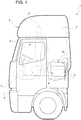
figure 1 is a side view, with parts removed for greater clarity, of a cab for a heavy vehicle according to the invention; -
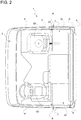
figure 2 is a view from the top of the cab offigure 1 ; -
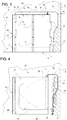
figure 3 is a side view, on a larger scale, of a collapsible storage box arranged inside the cabin in an extended configuration; -
figure 4 is similar tofigure 3 and shows the storage box in a collapsed configuration; and -
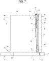
figures 5, 6 and7 show the storage box from the top while shifting from the extended configuration to the collapsed configuration. - In
figure 1 ,number 1 indicates, as a whole, a heavy vehicle provided with acab 2 designed to accommodate a driver U and, if necessary, a passenger (who is not shown). - The
cab 2 comprises a knownouter structure 4, for example provided with a plurality of walls connected to one another, among which there is afloor 3, which is fixed on the inside of theouter structure 4 so as to define, with the latter, ahabitable volume 5 for the driver U. - Evidently, the term "habitable" has to be interpreted with its most common and consolidated meaning, namely large enough to allow a medium-build grown-up person to easily walk inside it in a completely straight position. Therefore, for example, the volume defined by a trunk for a motor vehicle or the inner volume of a minivan cannot be considered as "habitable" volumes.
- Furthermore, the
cab 2 comprises a driver's seat S1, which is oriented in a normal direction of movement of thevehicle 1, and a passenger's seat S2 next to the seat S1. - Beside the seats S1, S2, the
outer structure 4 is provided with respective doors P so as to allow the users of the vehicle to get into thecab 1. - Furthermore, the
outer structure 4 comprises at least oneopening 6, which further establishes a communication between thevolume 5 and the outside of thecab 2. - More in detail, according to
figure 2 , thestructure 4 comprises twoopenings 6, which are respectively located on respective side walls of thestructure 4, facing one another and preferably coaxial to one another as well as arranged slightly above thefloor 3 behind the doors P, according to the direction of movement of thevehicle 1. - The aim of the
openings 6 is that of allowing the users of the vehicle to insert possible objects into thevolume 5 from the outside of thecab 2. - Each
opening 6 can be opened and closed according to the needs of the users of the vehicle, since thecab 2 comprises, for eachopening 6, a respective panel 7 (figures 5, 6 and7 ), which is carried by thestructure 4 in a known manner. Eachpanel 7 is preferably coupled to thestructure 4 in a rotary manner so as to rotate around a vertical axis A, namely by means of hinges, which are not shown herein. - At each
opening 6, in order to house the introduced objects in an orderly fashion, thecan 2 is provided, inside thevolume 5, with a relative storage box orlocker 10, which is carried by theouter structure 4 and/or by thefloor 3. - In this way, the objects housed therein do not create disorder inside the
volume 5, nor do they move in an uncontrolled manner when thevehicle 1 is moving. - In the example shown herein, the
cab 2 comprises twostorage lockers 10, which are respectively arranged behind the seats S1 and S2 and, in particular, are identical to one another, so that the description below will only discuss one of them for the sake of brevity. - The
locker 10 is collapsible or, better said, it can be configured between an extended configuration (figure 3 ), in which it delimits, on the inside, aspace 11 to be used to contain objects, and a collapsed configuration (figure 4 ), in which it occupied a reduced space compared to theaforesaid space 11. - Therefore, the
opening 6 is adjoined to thespace 11, namely it directly communicates with thespace 11, so as to allow objects to be directly introduced into thelocker 10 from the outside of thecab 2. - The
space 11 defines a reduced portion of thevolume 5; thelocker 10, in the extended configuration, is designed to isolate thespace 11 from the remaining portion of thevolume 5. - Basically, the space occupied by each
locker 10 in the collapsed configuration is substantially irrelevant, so that part of thevolume 5 behind the seat S1, S2 is free and can be used for other purposes other than storing objects. - More in detail, the
locker 10 comprises awall 12, which is carried by thestructure 4 and/or by thefloor 3, specifically in a fixed position, and a foldablestructural assembly 13, which is coupled to thewall 12 in a movable manner between an unfolded condition and a folded condition, which are respectively associated with the extended configuration and with the collapsed configuration of thelocker 10. - In the embodiment shown herein, the
wall 12 has a modelled shape such as to define acavity 14, which is suited to house theassembly 13 in the folded condition. - The
assembly 13 comprises awall 15, which is permanently coupled to thewall 12 in a movable manner between a position of maximum distance from thewall 12, which corresponds to the unfolded condition of thefoldable assembly 13, and a position of minimum distance from thewall 12, which corresponds to the folded condition of thefoldable assembly 13. - Specifically, the
wall 15 is substantially flat and vertical as well as transverse to the sides of thestructure 4, when theassembly 13 is in the unfolded condition. - Furthermore, the
assembly 13 comprises twofurther walls 16, which are arranged between thewall 12 and thewall 15, are coupled to one another and, moreover, are respectively coupled to thewalls - In particular, the
walls 16 are hinged to one another around a vertical hinge axis B and they are respectively hinged to thewalls - More in particular, the
walls 16 are substantially flat and vertical, are coplanar and face theopening 6, when thefoldable assembly 13 is in the unfolded condition. - In other words, the couplings between the
walls respective hinges 17, which allow thewalls 16 to be folded in a "accordion-like" manner. - As a whole, in the unfolded condition of the assembly 13 (
figure 5 ), thewalls structure 4 horizontally delimit thespace 11, which can directly be accessed after having opened thepanel 7. - The
space 11 can further be accessed from the top, from the inside of thevolume 5, since thelocker 10 is provided with adoor 27, which is coupled to thewall 12 in a rotary manner so as to rotate around a horizontal axis F, in particular through hinges (figures 3 and 4 ). - In the extended configuration of the
locker 10, thedoor 27 extends horizontally from thewall 12 until it ends with an end resting against thewall 15, so as to close thespace 11 from the top. Hence, in order to introduce objects into thespace 11, the driver U can lift thedoor 27, thus opening thespace 11 from the inside of thevolume 5 without having to go out of the vehicle, namely from thepanel 7. - On the other hand, in the collapsed configuration, the
door 27 faces downwards in a position adjacent to thewall 12, so as to partially close thecavity 14. In this case, thedoor 27, through its weight, prevents theassembly 13 from coming out of thecavity 14 in an uncontrolled manner. - Accordingly, as per
figure 7 , thewalls 16 are folded against one another between thewalls wall 15 is approximately parallel to thewalls 16. - Conveniently, in order to prevent the
locker 10 from accidentally shifting from the extended configuration to the collapsed configuration, thecab 2 comprises anattachment element 18, which is fixed relative to thestructure 4, in particular protrudes upwards from thefloor 3, whereas thewall 15 ends with an attachment end 19 opposite thewalls 16. - More in particular, the
attachment element 18 is defined by a vertical bar having an "L"-shaped cross section and comprises aportion 20, which extends from thestructure 4 towards the inside of thecabin 2, and aportion 21, which extends in a cantilever manner from theportion 20 parallel to the side and defines, with theportion 20, a recess 22 (figure 6 and7 ). - Accordingly, the
attachment end 19 also has an "L"-shaped cross section, so as to engage therecess 22 when theassembly 13 is in the unfolded condition. - In this way, the
wall 15 and, consequently, thewalls 16 are prevented from freely moving along a direction which is perpendicular to the side, until thewall 15 is pushed in a direction contrary to the direction of movement in order to remove theattachment end 19 from therecess 22. - Alternatively or in addition, the
assembly 13 comprises awall 25, which can rotate around a horizontal axis E between a lowered position, which is associated with the unfolded condition of theassembly 13 and in which thewall 25 defines a bottom of thelocker 10, and a lifted position, which is associated with the folded condition of theassembly 13 and in which thewall 25 is housed in thecavity 14. - More in detail, the
wall 25 is hinged to thewall 12; in the example offigure 4 , to this purpose, twohinges 26 are provided. - At the end opposite the
hinge 26, thewall 25 carries a protuberance orprojection 29, which extends transversely to thewall 25 so as to horizontally face thewall 15 when thelocker 10 is in the extended configuration. - In this way, as long as the
wall 25 is not lifted, theprojection 29 prevents thewall 15 from moving in a direction contrary to the direction of movement of thevehicle 1. - Hence, the
projection 29 and theattachment element 18 define retention elements to keep thelocker 10 in the extended configuration. - Advantageously, the
cab 2 comprises aguide 33, specifically a straight guide, which is flush with thewall 3, so as not to interfere with thewall 25, and is fixed to thefloor 3; the seat S2 is coupled to theguide 33 in a sliding manner between an advanced position, in which it is spaced apart from therelative locker 10 in the extended configuration, and a retracted position, in which it occupies part of the space freed by thelocker 10 in the collapsed configuration. Therefore, in order to move the seat S2 to the retracted position, therelative locker 10 needs to shift to the collapsed configuration. - The embodiment of the
cab 2 described above works as follows. - When one of the users of the vehicle needs in a different manner to use the space occupied by one of the
lockers 10, for example the one behind the seat S2, the same user moves behind the seat S2, where thelocker 10 is in the extended configuration. - There, the user lifts the
door 27 and removes possible objects present in thespace 11. Then, the user lifts thewall 25 from the lowered position (figure 4 ) . At this point, thewall 15 simply needs to be pushed in a direction contrary to the direction of movement of thevehicle 1, so that theattachment end 19 gets out of therecess 22. - Then, if the user keeps pushing the
wall 15, the axis B moves towards the inside of thespace 11 so as to fold thewalls assembly 13 is in the folded configuration (figures 5, 6 and7 ). - Finally, the user releases the
door 27, which, because of gravity, reaches a vertical position adjacent to thewall 12, so that thelocker 10 is in the collapsed configuration and the seat S2 can be moved to the retracted position. - When the user does not need to use the space left free by the
locker 10 any longer, the user can carry out the same operations described above in a reverse order. - Owing to the above, the advantages of a cab according to the invention are evident.
- Thanks to the fact that the
lockers 10 can be reconfigured, the user of the vehicle has the chance to choose, based on specific circumstances, whether to have the possibility of safely storing objects in an orderly fashion in thespace 11 or whether to give up this possibility and use the spaces left free by the collapse thelockers 10 for other purposes, such as, for example, for moving the seat S2 to the retracted position. - This movement of the seat S2 to the retracted position allows users to have a larger habitable space in the area of one of the doors P, so that, furthermore, getting into and out of the
volume 5 becomes easier. - Therefore, the habitable space of the
cabin 2 is larger compared to known solutions and, furthermore, a greater number of accessories, such as, for example, tables, monitors, fridges, can be accommodated inside thevolume 5. - Furthermore, the specific constructive shape of the
assembly 13 is sturdy and, at the same time, particularly simple to be folded, as well as extremely compact when it is folded. Theattachment element 18 and theprojection 29 help increase the sturdiness and the safety of theentire locker 10. - Finally, the
cab 2 according to the invention can be subjected to changes and variants, which, though, do not go beyond the scope of protection set forth in the appended claims. - In particular, the constructive shape of the
locker 10 could be different than the one described and shown herein; for example, thelocker 10 could comprise flexible walls or different rigid portions connected to one another by means of flexible portions, or even telescopic portions. - More in particular, the
wall 25 could be absent and thehinges 17 could be replaced by other types of connection, for example virtual hinges. - The
lockers 10 could be raised relative to thefloor 3 and be supported by thesole structure 4, or they could be supported by thesole floor 3. - Finally, the seat S1 could be moved to a retracted position, like the seat S2.
Claims (12)
- A cab (2) for a heavy vehicle (1) comprising:• a structure (3, 4) which internally defines a habitable volume (5) and comprises an opening (6) for selectively establishing communication of said habitable volume (5) with the outside of the cab (2); and• a storage box (10) arranged inside said habitable volume (5) in an extended configuration, in which it delimits a first space (11) selectively accessible by means of said opening (6), and carried by said structure (4);wherein said box (10) is configurable between said extended configuration and a collapsed configuration, in which it occupies a second space reduced with respect to said first space (11);characterized in that said box (10) comprises a first wall (12) carried by said structure (4, 3) in a fixed position and a foldable structural assembly (13) coupled to said first wall (12).
- The cab according to claim 1, wherein said first wall (12) is fixed with respect to said structure (4, 3) and defines a cavity (14) which houses said foldable structural assembly (13) when said box (10) is in the collapsed configuration.
- The cab according to claim 2, comprising a door (27) coupled to said first wall (12) in a rotating manner around a first horizontal axis (F), so as to be movable between a horizontal position, in which it closes said first space (11) at the top, and a vertical position, in which it faces downwards and defines, by means of its weight, a containment means for keeping said foldable structural assembly (13) inside said cavity (14) when said box (10) is in the collapsed configuration.
- The cab according to any one of the foregoing claims, wherein said foldable structural assembly (13) comprises a second wall (15), vertical and permanently coupled in a movable manner to said first wall (12), so as to be closer to said first wall (12) when said box (10) is in the collapsed configuration with respect to when said box (10) is in the extended configuration; said second wall (15) being transverse to said opening (6) in the extended configuration.
- The cab according to claim 4, comprising releasable retention means (18, 29) configured to keep said box (10) in the extended configuration.
- The cab according to claim 5, wherein said releasable retention means (18, 29) comprise an attachment element (18) fixed with respect to said structure (4, 3); said second wall (15) having an attachment end (19), which is coupled to said attachment element (18) when said box (10) is in the extended configuration.
- The cab according to claim 5 or 6, wherein said foldable structural assembly (13) comprises a third wall (25) substantially flat and coupled to said first wall (12) in a rotating manner around a second horizontal axis (E) to be arranged in a horizontal position, in which it defines a bottom for said box (10) in the extended configuration; said retention means (18, 29) comprising a projection (29) transverse with respect to said third wall (25), carried by one end of said third wall (25) opposite said second horizontal axis (E) and facing said second wall (15) when said box (10) is in the extended configuration.
- The cab according to any one of the claims from 4 to 7, wherein said foldable structural assembly (13) comprises at least a fourth vertical wall (16) permanently coupled to said first and second wall (12, 15); and wherein:said fourth wall (16) is rotatable with respect to said first wall around at least one vertical axis (B, C, D); andsaid fourth wall (16) faces said opening (6) when said box (10) is in the extended configuration.
- The cab according to any one of the preceding claims, characterized in that said first space (11) is horizontally delimited by said structure (4), so as to be directly accessible through said opening (6).
- The cab according to any one of the preceding claims, comprising a seat (S1, S2) movable with respect to said structure (4, 3) between an advanced and a retracted position according to a direction of movement of said heavy vehicle (1); said box (10) being arranged behind said seat (S1, S2) according to said direction of movement and said seat (S1, S2) occupying, in the retracted position, a first portion of said habitable volume (5) at least partly occupied by said box (10) in the extended configuration.
- The cab according to any one of the preceding claims, wherein said opening (6) selectively communicates by means of a panel (7) carried in a movable manner by one of said box (10) and said structure (4) to close and open said opening (6) thus allowing said volume (5) to communicate with the outside.
- A heavy vehicle (1) comprising a cab according to one of the preceding claims.
Applications Claiming Priority (1)
| Application Number | Priority Date | Filing Date | Title |
|---|---|---|---|
| IT102019000001737A IT201900001737A1 (en) | 2019-02-06 | 2019-02-06 | IMPROVED CAB FOR A HEAVY VEHICLE |
Publications (2)
| Publication Number | Publication Date |
|---|---|
| EP3693223A1 EP3693223A1 (en) | 2020-08-12 |
| EP3693223B1 true EP3693223B1 (en) | 2021-09-15 |
Family
ID=66380032
Family Applications (1)
| Application Number | Title | Priority Date | Filing Date |
|---|---|---|---|
| EP20155956.4A Active EP3693223B1 (en) | 2019-02-06 | 2020-02-06 | Cab with storage box for a heavy vehicle |
Country Status (3)
| Country | Link |
|---|---|
| EP (1) | EP3693223B1 (en) |
| ES (1) | ES2902602T3 (en) |
| IT (1) | IT201900001737A1 (en) |
Families Citing this family (1)
| Publication number | Priority date | Publication date | Assignee | Title |
|---|---|---|---|---|
| JP2022184398A (en) * | 2021-06-01 | 2022-12-13 | キャタピラー エス エー アール エル | Storage device, cab, and work machine |
Family Cites Families (5)
| Publication number | Priority date | Publication date | Assignee | Title |
|---|---|---|---|---|
| DE19711035C1 (en) * | 1997-03-17 | 1998-07-23 | Daimler Benz Ag | Partition for variable sub-division of storage compartment, e.g. vehicle boot |
| DE102004025248A1 (en) * | 2004-05-22 | 2005-12-08 | Daimlerchrysler Ag | Driver's cab for heavy goods vehicle has transverse tunnel under rear seat or rear parcel shelf with side rails accommodating rollers on drawers holding small containers |
| US7762601B2 (en) * | 2008-08-29 | 2010-07-27 | Nissan Technical Center North America, Inc. | Vehicle container interface |
| DE102009052594A1 (en) * | 2009-11-10 | 2011-05-12 | GM Global Technology Operations LLC, Detroit | Method and coupling device for stowing a motor vehicle seat |
| DE102015012624A1 (en) * | 2015-09-26 | 2017-03-30 | Man Truck & Bus Ag | Storage compartment construction for a commercial vehicle, in particular for a truck |
-
2019
- 2019-02-06 IT IT102019000001737A patent/IT201900001737A1/en unknown
-
2020
- 2020-02-06 EP EP20155956.4A patent/EP3693223B1/en active Active
- 2020-02-06 ES ES20155956T patent/ES2902602T3/en active Active
Also Published As
| Publication number | Publication date |
|---|---|
| EP3693223A1 (en) | 2020-08-12 |
| IT201900001737A1 (en) | 2020-08-06 |
| ES2902602T3 (en) | 2022-03-29 |
Similar Documents
| Publication | Publication Date | Title |
|---|---|---|
| EP3835225B1 (en) | Foldable container | |
| US6644710B2 (en) | Box container and loading space for a motor vehicle | |
| US12590487B2 (en) | Multi-access liftgate | |
| US7469948B2 (en) | Apparatus for extending vehicle cargo space and method for same | |
| EP3061636A1 (en) | Tailgate with load area extender for utility motor vehicle, and motor vehicle | |
| MX2015000883A (en) | Multi-function automotive trunk storage drawer. | |
| US20110074175A1 (en) | Vehicle Rear End Assemblies with Storage Assemblies | |
| US10399505B1 (en) | Collapsable pickup truck storage compartment | |
| US6827231B2 (en) | Minivan box liner | |
| EP3693223B1 (en) | Cab with storage box for a heavy vehicle | |
| EP4349655B1 (en) | A storage console for a vehicle | |
| US20040256873A1 (en) | Apparatus for configuring the cargo area of a vehicle | |
| CN118665612A (en) | Multifunctional cargo maximizing apparatus | |
| US11511676B2 (en) | Vehicle storage system | |
| KR101701095B1 (en) | Cover assembly for open top truck body | |
| CN220363202U (en) | Vehicle with a vehicle body having a vehicle body support | |
| JP3283006B2 (en) | Car luggage room structure | |
| KR101438634B1 (en) | Folding case of trunk side trim | |
| CN218858264U (en) | Kitchen truck device based on external part shelter | |
| KR102257810B1 (en) | Camping Apparatus with Support Frame | |
| JP4626077B2 (en) | Rear cargo compartment structure of vehicle | |
| JP5760777B2 (en) | Rear cargo compartment structure of vehicle | |
| US20230202400A1 (en) | Configurable storage compartments | |
| KR20260063605A (en) | Center gate device for pickup truck | |
| CN119928699A (en) | A car kitchen |
Legal Events
| Date | Code | Title | Description |
|---|---|---|---|
| PUAI | Public reference made under article 153(3) epc to a published international application that has entered the european phase |
Free format text: ORIGINAL CODE: 0009012 |
|
| STAA | Information on the status of an ep patent application or granted ep patent |
Free format text: STATUS: THE APPLICATION HAS BEEN PUBLISHED |
|
| AK | Designated contracting states |
Kind code of ref document: A1 Designated state(s): AL AT BE BG CH CY CZ DE DK EE ES FI FR GB GR HR HU IE IS IT LI LT LU LV MC MK MT NL NO PL PT RO RS SE SI SK SM TR |
|
| AX | Request for extension of the european patent |
Extension state: BA ME |
|
| STAA | Information on the status of an ep patent application or granted ep patent |
Free format text: STATUS: REQUEST FOR EXAMINATION WAS MADE |
|
| 17P | Request for examination filed |
Effective date: 20210210 |
|
| RBV | Designated contracting states (corrected) |
Designated state(s): AL AT BE BG CH CY CZ DE DK EE ES FI FR GB GR HR HU IE IS IT LI LT LU LV MC MK MT NL NO PL PT RO RS SE SI SK SM TR |
|
| GRAP | Despatch of communication of intention to grant a patent |
Free format text: ORIGINAL CODE: EPIDOSNIGR1 |
|
| STAA | Information on the status of an ep patent application or granted ep patent |
Free format text: STATUS: GRANT OF PATENT IS INTENDED |
|
| RIC1 | Information provided on ipc code assigned before grant |
Ipc: B62D 33/06 20060101ALI20210305BHEP Ipc: B60R 7/04 20060101ALI20210305BHEP Ipc: B60R 7/02 20060101AFI20210305BHEP |
|
| INTG | Intention to grant announced |
Effective date: 20210406 |
|
| RAP3 | Party data changed (applicant data changed or rights of an application transferred) |
Owner name: IVECO S.P.A. |
|
| GRAS | Grant fee paid |
Free format text: ORIGINAL CODE: EPIDOSNIGR3 |
|
| GRAA | (expected) grant |
Free format text: ORIGINAL CODE: 0009210 |
|
| STAA | Information on the status of an ep patent application or granted ep patent |
Free format text: STATUS: THE PATENT HAS BEEN GRANTED |
|
| AK | Designated contracting states |
Kind code of ref document: B1 Designated state(s): AL AT BE BG CH CY CZ DE DK EE ES FI FR GB GR HR HU IE IS IT LI LT LU LV MC MK MT NL NO PL PT RO RS SE SI SK SM TR |
|
| REG | Reference to a national code |
Ref country code: CH Ref legal event code: EP |
|
| REG | Reference to a national code |
Ref country code: DE Ref legal event code: R096 Ref document number: 602020000533 Country of ref document: DE |
|
| REG | Reference to a national code |
Ref country code: IE Ref legal event code: FG4D |
|
| REG | Reference to a national code |
Ref country code: AT Ref legal event code: REF Ref document number: 1430277 Country of ref document: AT Kind code of ref document: T Effective date: 20211015 |
|
| REG | Reference to a national code |
Ref country code: LT Ref legal event code: MG9D |
|
| REG | Reference to a national code |
Ref country code: NL Ref legal event code: MP Effective date: 20210915 |
|
| PG25 | Lapsed in a contracting state [announced via postgrant information from national office to epo] |
Ref country code: LT Free format text: LAPSE BECAUSE OF FAILURE TO SUBMIT A TRANSLATION OF THE DESCRIPTION OR TO PAY THE FEE WITHIN THE PRESCRIBED TIME-LIMIT Effective date: 20210915 Ref country code: BG Free format text: LAPSE BECAUSE OF FAILURE TO SUBMIT A TRANSLATION OF THE DESCRIPTION OR TO PAY THE FEE WITHIN THE PRESCRIBED TIME-LIMIT Effective date: 20211215 Ref country code: FI Free format text: LAPSE BECAUSE OF FAILURE TO SUBMIT A TRANSLATION OF THE DESCRIPTION OR TO PAY THE FEE WITHIN THE PRESCRIBED TIME-LIMIT Effective date: 20210915 Ref country code: HR Free format text: LAPSE BECAUSE OF FAILURE TO SUBMIT A TRANSLATION OF THE DESCRIPTION OR TO PAY THE FEE WITHIN THE PRESCRIBED TIME-LIMIT Effective date: 20210915 Ref country code: NO Free format text: LAPSE BECAUSE OF FAILURE TO SUBMIT A TRANSLATION OF THE DESCRIPTION OR TO PAY THE FEE WITHIN THE PRESCRIBED TIME-LIMIT Effective date: 20211215 Ref country code: RS Free format text: LAPSE BECAUSE OF FAILURE TO SUBMIT A TRANSLATION OF THE DESCRIPTION OR TO PAY THE FEE WITHIN THE PRESCRIBED TIME-LIMIT Effective date: 20210915 Ref country code: SE Free format text: LAPSE BECAUSE OF FAILURE TO SUBMIT A TRANSLATION OF THE DESCRIPTION OR TO PAY THE FEE WITHIN THE PRESCRIBED TIME-LIMIT Effective date: 20210915 |
|
| REG | Reference to a national code |
Ref country code: AT Ref legal event code: MK05 Ref document number: 1430277 Country of ref document: AT Kind code of ref document: T Effective date: 20210915 |
|
| PG25 | Lapsed in a contracting state [announced via postgrant information from national office to epo] |
Ref country code: LV Free format text: LAPSE BECAUSE OF FAILURE TO SUBMIT A TRANSLATION OF THE DESCRIPTION OR TO PAY THE FEE WITHIN THE PRESCRIBED TIME-LIMIT Effective date: 20210915 Ref country code: GR Free format text: LAPSE BECAUSE OF FAILURE TO SUBMIT A TRANSLATION OF THE DESCRIPTION OR TO PAY THE FEE WITHIN THE PRESCRIBED TIME-LIMIT Effective date: 20211216 |
|
| REG | Reference to a national code |
Ref country code: ES Ref legal event code: FG2A Ref document number: 2902602 Country of ref document: ES Kind code of ref document: T3 Effective date: 20220329 |
|
| PG25 | Lapsed in a contracting state [announced via postgrant information from national office to epo] |
Ref country code: AT Free format text: LAPSE BECAUSE OF FAILURE TO SUBMIT A TRANSLATION OF THE DESCRIPTION OR TO PAY THE FEE WITHIN THE PRESCRIBED TIME-LIMIT Effective date: 20210915 |
|
| PG25 | Lapsed in a contracting state [announced via postgrant information from national office to epo] |
Ref country code: IS Free format text: LAPSE BECAUSE OF FAILURE TO SUBMIT A TRANSLATION OF THE DESCRIPTION OR TO PAY THE FEE WITHIN THE PRESCRIBED TIME-LIMIT Effective date: 20220115 Ref country code: SM Free format text: LAPSE BECAUSE OF FAILURE TO SUBMIT A TRANSLATION OF THE DESCRIPTION OR TO PAY THE FEE WITHIN THE PRESCRIBED TIME-LIMIT Effective date: 20210915 Ref country code: SK Free format text: LAPSE BECAUSE OF FAILURE TO SUBMIT A TRANSLATION OF THE DESCRIPTION OR TO PAY THE FEE WITHIN THE PRESCRIBED TIME-LIMIT Effective date: 20210915 Ref country code: RO Free format text: LAPSE BECAUSE OF FAILURE TO SUBMIT A TRANSLATION OF THE DESCRIPTION OR TO PAY THE FEE WITHIN THE PRESCRIBED TIME-LIMIT Effective date: 20210915 Ref country code: PT Free format text: LAPSE BECAUSE OF FAILURE TO SUBMIT A TRANSLATION OF THE DESCRIPTION OR TO PAY THE FEE WITHIN THE PRESCRIBED TIME-LIMIT Effective date: 20220117 Ref country code: PL Free format text: LAPSE BECAUSE OF FAILURE TO SUBMIT A TRANSLATION OF THE DESCRIPTION OR TO PAY THE FEE WITHIN THE PRESCRIBED TIME-LIMIT Effective date: 20210915 Ref country code: NL Free format text: LAPSE BECAUSE OF FAILURE TO SUBMIT A TRANSLATION OF THE DESCRIPTION OR TO PAY THE FEE WITHIN THE PRESCRIBED TIME-LIMIT Effective date: 20210915 Ref country code: EE Free format text: LAPSE BECAUSE OF FAILURE TO SUBMIT A TRANSLATION OF THE DESCRIPTION OR TO PAY THE FEE WITHIN THE PRESCRIBED TIME-LIMIT Effective date: 20210915 Ref country code: CZ Free format text: LAPSE BECAUSE OF FAILURE TO SUBMIT A TRANSLATION OF THE DESCRIPTION OR TO PAY THE FEE WITHIN THE PRESCRIBED TIME-LIMIT Effective date: 20210915 Ref country code: AL Free format text: LAPSE BECAUSE OF FAILURE TO SUBMIT A TRANSLATION OF THE DESCRIPTION OR TO PAY THE FEE WITHIN THE PRESCRIBED TIME-LIMIT Effective date: 20210915 |
|
| REG | Reference to a national code |
Ref country code: DE Ref legal event code: R097 Ref document number: 602020000533 Country of ref document: DE |
|
| PLBE | No opposition filed within time limit |
Free format text: ORIGINAL CODE: 0009261 |
|
| STAA | Information on the status of an ep patent application or granted ep patent |
Free format text: STATUS: NO OPPOSITION FILED WITHIN TIME LIMIT |
|
| PG25 | Lapsed in a contracting state [announced via postgrant information from national office to epo] |
Ref country code: DK Free format text: LAPSE BECAUSE OF FAILURE TO SUBMIT A TRANSLATION OF THE DESCRIPTION OR TO PAY THE FEE WITHIN THE PRESCRIBED TIME-LIMIT Effective date: 20210915 |
|
| 26N | No opposition filed |
Effective date: 20220616 |
|
| PG25 | Lapsed in a contracting state [announced via postgrant information from national office to epo] |
Ref country code: SI Free format text: LAPSE BECAUSE OF FAILURE TO SUBMIT A TRANSLATION OF THE DESCRIPTION OR TO PAY THE FEE WITHIN THE PRESCRIBED TIME-LIMIT Effective date: 20210915 |
|
| PG25 | Lapsed in a contracting state [announced via postgrant information from national office to epo] |
Ref country code: MC Free format text: LAPSE BECAUSE OF FAILURE TO SUBMIT A TRANSLATION OF THE DESCRIPTION OR TO PAY THE FEE WITHIN THE PRESCRIBED TIME-LIMIT Effective date: 20210915 |
|
| REG | Reference to a national code |
Ref country code: BE Ref legal event code: MM Effective date: 20220228 |
|
| PG25 | Lapsed in a contracting state [announced via postgrant information from national office to epo] |
Ref country code: LU Free format text: LAPSE BECAUSE OF NON-PAYMENT OF DUE FEES Effective date: 20220206 |
|
| PG25 | Lapsed in a contracting state [announced via postgrant information from national office to epo] |
Ref country code: IE Free format text: LAPSE BECAUSE OF NON-PAYMENT OF DUE FEES Effective date: 20220206 |
|
| PG25 | Lapsed in a contracting state [announced via postgrant information from national office to epo] |
Ref country code: BE Free format text: LAPSE BECAUSE OF NON-PAYMENT OF DUE FEES Effective date: 20220228 |
|
| P01 | Opt-out of the competence of the unified patent court (upc) registered |
Effective date: 20230523 |
|
| REG | Reference to a national code |
Ref country code: CH Ref legal event code: PL |
|
| PG25 | Lapsed in a contracting state [announced via postgrant information from national office to epo] |
Ref country code: LI Free format text: LAPSE BECAUSE OF NON-PAYMENT OF DUE FEES Effective date: 20230228 Ref country code: CH Free format text: LAPSE BECAUSE OF NON-PAYMENT OF DUE FEES Effective date: 20230228 |
|
| PG25 | Lapsed in a contracting state [announced via postgrant information from national office to epo] |
Ref country code: MK Free format text: LAPSE BECAUSE OF FAILURE TO SUBMIT A TRANSLATION OF THE DESCRIPTION OR TO PAY THE FEE WITHIN THE PRESCRIBED TIME-LIMIT Effective date: 20210915 Ref country code: CY Free format text: LAPSE BECAUSE OF FAILURE TO SUBMIT A TRANSLATION OF THE DESCRIPTION OR TO PAY THE FEE WITHIN THE PRESCRIBED TIME-LIMIT Effective date: 20210915 |
|
| PG25 | Lapsed in a contracting state [announced via postgrant information from national office to epo] |
Ref country code: HU Free format text: LAPSE BECAUSE OF FAILURE TO SUBMIT A TRANSLATION OF THE DESCRIPTION OR TO PAY THE FEE WITHIN THE PRESCRIBED TIME-LIMIT; INVALID AB INITIO Effective date: 20200206 |
|
| PG25 | Lapsed in a contracting state [announced via postgrant information from national office to epo] |
Ref country code: TR Free format text: LAPSE BECAUSE OF FAILURE TO SUBMIT A TRANSLATION OF THE DESCRIPTION OR TO PAY THE FEE WITHIN THE PRESCRIBED TIME-LIMIT Effective date: 20210915 |
|
| PG25 | Lapsed in a contracting state [announced via postgrant information from national office to epo] |
Ref country code: MT Free format text: LAPSE BECAUSE OF FAILURE TO SUBMIT A TRANSLATION OF THE DESCRIPTION OR TO PAY THE FEE WITHIN THE PRESCRIBED TIME-LIMIT Effective date: 20210915 |
|
| PGFP | Annual fee paid to national office [announced via postgrant information from national office to epo] |
Ref country code: GB Payment date: 20260223 Year of fee payment: 7 |
|
| PGFP | Annual fee paid to national office [announced via postgrant information from national office to epo] |
Ref country code: ES Payment date: 20260317 Year of fee payment: 7 |
|
| PGFP | Annual fee paid to national office [announced via postgrant information from national office to epo] |
Ref country code: DE Payment date: 20260220 Year of fee payment: 7 |
|
| PGFP | Annual fee paid to national office [announced via postgrant information from national office to epo] |
Ref country code: IT Payment date: 20260209 Year of fee payment: 7 |
|
| PGFP | Annual fee paid to national office [announced via postgrant information from national office to epo] |
Ref country code: FR Payment date: 20260227 Year of fee payment: 7 |