EP3693217B1 - Linear motion transmission device between a first and a second component with a force limiter function, in particular applicable to a lighting device for vehicles - Google Patents
Linear motion transmission device between a first and a second component with a force limiter function, in particular applicable to a lighting device for vehicles Download PDFInfo
- Publication number
- EP3693217B1 EP3693217B1 EP20156226.1A EP20156226A EP3693217B1 EP 3693217 B1 EP3693217 B1 EP 3693217B1 EP 20156226 A EP20156226 A EP 20156226A EP 3693217 B1 EP3693217 B1 EP 3693217B1
- Authority
- EP
- European Patent Office
- Prior art keywords
- cup
- bushing
- shaped body
- support
- shaft
- Prior art date
- Legal status (The legal status is an assumption and is not a legal conclusion. Google has not performed a legal analysis and makes no representation as to the accuracy of the status listed.)
- Active
Links
Images



Classifications
-
- B—PERFORMING OPERATIONS; TRANSPORTING
- B60—VEHICLES IN GENERAL
- B60Q—ARRANGEMENT OF SIGNALLING OR LIGHTING DEVICES, THE MOUNTING OR SUPPORTING THEREOF OR CIRCUITS THEREFOR, FOR VEHICLES IN GENERAL
- B60Q1/00—Arrangement of optical signalling or lighting devices, the mounting or supporting thereof or circuits therefor
- B60Q1/02—Arrangement of optical signalling or lighting devices, the mounting or supporting thereof or circuits therefor the devices being primarily intended to illuminate the way ahead or to illuminate other areas of way or environments
- B60Q1/04—Arrangement of optical signalling or lighting devices, the mounting or supporting thereof or circuits therefor the devices being primarily intended to illuminate the way ahead or to illuminate other areas of way or environments the devices being headlights
- B60Q1/06—Arrangement of optical signalling or lighting devices, the mounting or supporting thereof or circuits therefor the devices being primarily intended to illuminate the way ahead or to illuminate other areas of way or environments the devices being headlights adjustable, e.g. remotely-controlled from inside vehicle
- B60Q1/076—Arrangement of optical signalling or lighting devices, the mounting or supporting thereof or circuits therefor the devices being primarily intended to illuminate the way ahead or to illuminate other areas of way or environments the devices being headlights adjustable, e.g. remotely-controlled from inside vehicle by electrical means including means to transmit the movements, e.g. shafts or joints
-
- F—MECHANICAL ENGINEERING; LIGHTING; HEATING; WEAPONS; BLASTING
- F21—LIGHTING
- F21S—NON-PORTABLE LIGHTING DEVICES; SYSTEMS THEREOF; VEHICLE LIGHTING DEVICES SPECIALLY ADAPTED FOR VEHICLE EXTERIORS
- F21S41/00—Illuminating devices specially adapted for vehicle exteriors, e.g. headlamps
- F21S41/60—Illuminating devices specially adapted for vehicle exteriors, e.g. headlamps characterised by a variable light distribution
- F21S41/65—Illuminating devices specially adapted for vehicle exteriors, e.g. headlamps characterised by a variable light distribution by acting on light sources
- F21S41/657—Illuminating devices specially adapted for vehicle exteriors, e.g. headlamps characterised by a variable light distribution by acting on light sources by moving light sources
-
- F—MECHANICAL ENGINEERING; LIGHTING; HEATING; WEAPONS; BLASTING
- F21—LIGHTING
- F21S—NON-PORTABLE LIGHTING DEVICES; SYSTEMS THEREOF; VEHICLE LIGHTING DEVICES SPECIALLY ADAPTED FOR VEHICLE EXTERIORS
- F21S41/00—Illuminating devices specially adapted for vehicle exteriors, e.g. headlamps
- F21S41/60—Illuminating devices specially adapted for vehicle exteriors, e.g. headlamps characterised by a variable light distribution
- F21S41/67—Illuminating devices specially adapted for vehicle exteriors, e.g. headlamps characterised by a variable light distribution by acting on reflectors
- F21S41/675—Illuminating devices specially adapted for vehicle exteriors, e.g. headlamps characterised by a variable light distribution by acting on reflectors by moving reflectors
-
- F—MECHANICAL ENGINEERING; LIGHTING; HEATING; WEAPONS; BLASTING
- F21—LIGHTING
- F21S—NON-PORTABLE LIGHTING DEVICES; SYSTEMS THEREOF; VEHICLE LIGHTING DEVICES SPECIALLY ADAPTED FOR VEHICLE EXTERIORS
- F21S43/00—Signalling devices specially adapted for vehicle exteriors, e.g. brake lamps, direction indicator lights or reversing lights
-
- F—MECHANICAL ENGINEERING; LIGHTING; HEATING; WEAPONS; BLASTING
- F21—LIGHTING
- F21V—FUNCTIONAL FEATURES OR DETAILS OF LIGHTING DEVICES OR SYSTEMS THEREOF; STRUCTURAL COMBINATIONS OF LIGHTING DEVICES WITH OTHER ARTICLES, NOT OTHERWISE PROVIDED FOR
- F21V14/00—Controlling the distribution of the light emitted by adjustment of elements
- F21V14/02—Controlling the distribution of the light emitted by adjustment of elements by movement of light sources
-
- F—MECHANICAL ENGINEERING; LIGHTING; HEATING; WEAPONS; BLASTING
- F21—LIGHTING
- F21V—FUNCTIONAL FEATURES OR DETAILS OF LIGHTING DEVICES OR SYSTEMS THEREOF; STRUCTURAL COMBINATIONS OF LIGHTING DEVICES WITH OTHER ARTICLES, NOT OTHERWISE PROVIDED FOR
- F21V14/00—Controlling the distribution of the light emitted by adjustment of elements
- F21V14/04—Controlling the distribution of the light emitted by adjustment of elements by movement of reflectors
-
- F—MECHANICAL ENGINEERING; LIGHTING; HEATING; WEAPONS; BLASTING
- F21—LIGHTING
- F21W—INDEXING SCHEME ASSOCIATED WITH SUBCLASSES F21K, F21L, F21S and F21V, RELATING TO USES OR APPLICATIONS OF LIGHTING DEVICES OR SYSTEMS
- F21W2102/00—Exterior vehicle lighting devices for illuminating purposes
- F21W2102/10—Arrangement or contour of the emitted light
- F21W2102/13—Arrangement or contour of the emitted light for high-beam region or low-beam region
-
- F—MECHANICAL ENGINEERING; LIGHTING; HEATING; WEAPONS; BLASTING
- F21—LIGHTING
- F21W—INDEXING SCHEME ASSOCIATED WITH SUBCLASSES F21K, F21L, F21S and F21V, RELATING TO USES OR APPLICATIONS OF LIGHTING DEVICES OR SYSTEMS
- F21W2107/00—Use or application of lighting devices on or in particular types of vehicles
- F21W2107/10—Use or application of lighting devices on or in particular types of vehicles for land vehicles
Definitions
- the present invention relates to a motion transmission device between a first and a second component with a force limiter function, in particular applicable to a lighting device for vehicles, where the first component is an electric motor and the second component is a reflector or lighting element of the lighting device, which must be moved, for example to direct a light beam generated by the lighting device while going round a bend and/or to adjust the direction of the light beam according to the load (passengers/baggage) weighing on the vehicle.
- a vehicle lighting device comprises a cup-shaped body or housing, generally made by moulding a synthetic plastic material, at least one lighting element housed in the cup-shaped body, fitted with a reflector or not, and a transparent element placed to close a front opening of the cup-shaped body, in use facing the direction of travel of the vehicle.
- an electro-mechanical device which moves the reflector or lighting element appropriately (at the user's or sensor's command) and which consists of an electric motor or linear actuator which acts on the reflector or lighting element via a mechanical transmission device.
- the mechanical transmission device may accidentally jam, causing an overload of the electric motor or actuator, and consequent premature wear or damage to the same.
- a transmission device according to the preamble of claim 1 is known from US 4 237 529 A .
- the purpose of the present invention is to provide a motion transmission device between a first and a second component, in particular applicable to a lighting device for vehicles, which is free of the drawbacks of the prior art, in particular having a force limiter function, and which is also simple and economical to make, highly reliable and small in size.
- a motion transmission device between a first and a second component with a force limiter function in particular applicable to a lighting device for vehicles, is therefore provided, as defined in the appended claims.
- the motion transmission device comprises a support for fixedly receiving the first component, an output shaft of the first component, axially mobile with respect to the support, a first shaft configured to be constrained in use to the second component, and a mechanical connection device between the axially mobile output shaft and the first shaft.
- the mechanical connection device comprises in turn: a cup-shaped body fixed to the first shaft and slidably coupled to the support parallel to the output shaft and coaxially thereto by means of at least one pair of lateral guides fixed to the support; a bushing, mounted inside the cup-shaped body, which is coaxial and slidable with respect thereto, the bushing being axially constrained in a fixed way to the output shaft so as to move integrally therewith; at least one pair of radial holes, made in a radially inner lateral surface of the cup-shaped body, said lateral surface cooperating with the bushing; at least one pair of opposed pegs, housed so that they can slide within respective radial seats of the bushing, which are provided within said bushing and until they pass through a radially outer lateral wall of the bushing, the radial seats further housing first springs which cooperate with the pegs, the first springs and the radial seats being configured to cause the pegs to selectively assume an extracted position, in which a
- first ends of the pegs are delimited by respective surfaces, arranged obliquely with respect to an axis of symmetry of the output shaft and of the bushing and configured to cooperate with a perimetral edge of the radial holes so as to push the pegs towards the retracted position, against the action of the first springs, as a result of any axial load applied in use to the first shaft that exceeds a threshold value.
- the bushing In this retracted position of the pegs, the bushing is no longer axially constrained to the cup-shaped body and is therefore free to move axially with respect to the same, as is the support, to which it is connected by means of the output shaft, against the action of the second springs.
- the output shaft even if it continues to move under the action of the first component, which is generally an electric motor or actuator, never receives axial stress higher than the established threshold value, preserving the first component.
- the first component which is generally an electric motor or actuator
- the established threshold value is determined in the design phase by appropriately sizing the first and second springs and the angle of inclination of the oblique surfaces with respect to the axis of movement of the output shaft.
- the mechanical connection device further comprises a second shaft configured to fixedly couple, on one side, to the output shaft of the first component and, on the opposite side, to the bushing; in addition, the second shaft connects to the bushing by means of a ball joint and, preferably, by snap action.
- the bushing preferably comprises an annular or cup-shaped drum, preferably cylindrical, which has a first end facing the first shaft and provided with the radial seats for the pegs and for the first springs; a cover for closing a second end of the drum, which is opposite to the first end and is open towards the support, the cover being provided with a hole for receiving the output shaft through it as far as into the drum; and a spherical joint, which fixedly receives the output shaft and cooperates in contact with a first inner lateral surface of the drum, the spherical joint being axially blocked inside the drum by the cover.
- the cup-shaped body is divided into two elements consisting of an annular element coupled frontally to a cup-shaped element and integrally connected to each other by means of detachable connection members, preferably screws; the cup-shaped element being provided with the radial holes and both the annular and cup-shaped elements being coaxial and configured to slidingly receive inside them the bushing.
- reference numeral 1 globally denotes a front headlamp for motor vehicles, configured to be fixed in a known manner, not illustrated for the sake of simplicity, to the chassis of a vehicle (also known and not illustrated).
- the lighting device 1 comprises a housing 2, generally cup-shaped, a light source 3, a reflector 4 and a lens 5, either clear (i.e. not altering a light beam L produced by the light source 3) or optically active, which closes the housing 2 at the front.
- the reflector 4 or, if absent, directly the light source 3 can be rotated vertically and/or horizontally by means of an adjustment device 6, known in its general structure, comprising an electric motor or actuator 7, a linear motion transmission device 8 from the motor/actuator 7 to the reflector 4 (or directly to the light source 3) and a manual trim adjuster 9, known and illustrated only schematically by dotted lines by a block, for simplicity.
- an adjustment device 6 known in its general structure, comprising an electric motor or actuator 7, a linear motion transmission device 8 from the motor/actuator 7 to the reflector 4 (or directly to the light source 3) and a manual trim adjuster 9, known and illustrated only schematically by dotted lines by a block, for simplicity.
- the motion transmission device 8 is used to transmit a linear motion between a first component (in the example shown, consisting of the motor/actuator 7) and a second component, the orientation/trim of which must be varied, in the example shown, consisting of the reflector 4, but more generally also consisting of light source 3 alone.
- the transmission device 8 is designed with a force limiter function to protect the first component or motor/actuator 7 from any overloads that could damage it.
- the transmission device 8 ( Figure 2 ) comprises a support 10 for fixedly receiving the first component 7, an output shaft 11 of the first component, such output shaft 11 being axially mobile with respect to the support 10, a first shaft 12, configured to be constrained in use to the second component 4 (or 3), and a mechanical connection device 13 between the axially mobile output shaft 11 and the first shaft 12.
- the mechanical connection device 13 comprises a cup-shaped body 14, in the example shown, delimited by a cylindrical side wall 15 and coupled relatively slidingly to the support 10, parallel to the output shaft 11 and coaxially thereto, by means of at least a pair of lateral guides 16 attached to the support 10 and from which they protrude axially in a cantilever manner towards the cup-shaped body 14 which, according to one aspect of the invention, is fixed to the first shaft 12.
- the mechanical connection device 13 further comprises a bushing 18 mounted inside the cup-shaped body 14, arranged coaxial to the cup-shaped body 14 and housed relatively slidingly with respect thereto, said bushing 18 being axially integral, in any known manner, to the output shaft 11, so as to move integrally therewith.
- the side wall 15 of the cup-shaped body 14 is provided at one of its radially internal lateral surfaces 19 ( Figure 4 ), with at least one pair of opposite radial holes 20 (which in the example shown are through holes, but which may also be blind), said radial holes 20 being preferably conical in shape.
- the lateral surface 19 also cooperates with the bushing 18, in the example shown in contact therewith, and is preferably cylindrically symmetrical.
- the mechanical connection device 13 further comprises at least one pair of opposite pegs 21 housed so as to slide in respective radial seats 22 of the bushing 18 ( Figures 4 and 5 ) made therein as far as through a radially external lateral wall 23 of the bushing 18.
- the radial seats 22 also house first springs 24 cooperating with the pegs 21.
- the springs 24 and the radial seats 22 are configured to make the pegs 21 selectively assume an extracted position ( Figure 3 ) and a retracted position ( Figures 6 and 7 ).
- a first end 25 of the pegs 21 protrudes radially cantilevered from the bushing 18 to engage the radial holes 20 of the cup-shaped body 14 and thus fix the cup-shaped body 14 to the bushing 18.
- the first end 25 of the pegs is at least partially housed in a concealed fashion in the radial seats 20 against the action of the first springs 24 so as not to engage the radial holes 20 of the cup-shaped body 14.
- the pegs 21 ( Figure 5 ) and seats 20 have bayonet couplings.
- the mechanical connection device 13 lastly comprises second springs 26, packed between the support 10 and the cup-shaped body 14 and between the support 10 and respective shoulder elements 27 ( Figure 5 ), which are fixed to the cup-shaped body 14 and are arranged, with respect to the support 10, on the side opposite to the cup-shaped body 14.
- the first ends 25 of the pegs 21 are delimited by respective surfaces 28 ( Figure 4 ) arranged obliquely with respect to an axis of symmetry A of the output shaft 11 and the bushing 18, in the non-limiting example illustrated defined by conical surfaces coaxial with the pegs 21.
- the oblique (conical) surfaces 28 are configured to cooperate with a perimeter edge 29 ( Figure 4 ), also conical in the non-limiting example shown, of the radial holes 20 to push the pegs 21 towards the retracted position, against the action of the first springs 24, as a result of any axial stress F ( Figures 6 and 7 ) applied in use to the first shaft 12 and exceeding a pre-set threshold value, for example calculated during the design phase, so that in the retracted position of the pegs 21 the bushing 18 is no longer axially constrained to the cup-shaped body 14 and is consequently free to move axially with respect to the cup-shaped body 14.
- the support 10 is also free to move in relation to the cup-shaped body 14 against the action of the springs 26, together (but not necessarily of the same magnitude) with the bushing 18.
- the mechanical connection device 13 further comprises a second shaft 29 configured to couple integrally, on one side, with the output shaft 11 of the first component 7 and, on the other side, with the bushing 18.
- the shaft 29 is connected to the bushing 18 by a ball joint 30, preferably designed to allow a snap connection with the shaft 29.
- the bushing 18 comprises: an annular or cup-shaped drum 31, preferably cylindrical, which has a first end 32 facing the first shaft 12 and provided with radial seats 22 for the pegs 21 and the springs 24; a cover 33 for closing a second end 34 of the drum 31, opposite the end 32 and open towards the support 10; and a spherical joint 35 ( Figure 5 ), which fixedly receives the output shaft 11 and cooperates in contact with a first inner lateral surface 36 of the drum 31.
- the cover 33 is provided with a hole 37 for receiving the output shaft 11 through it as far as into the drum 31 and the spherical joint 35 is axially blocked inside the drum 31 by the cover 33.
- the output shaft 11 is coupled, according to the preferred embodiment shown by way of a non-limiting example, integral with the second shaft 29, which is arranged coaxial with it and also housed inside the drum 31.
- the shaft 29 in turn couples to the spherical joint 35 radially inside thereof by means of the ball joint 30, which comprises a spherical head 38 made in one piece with the shaft 29 at a first end thereof opposite the output shaft 11, and a spherical receiving element 39 for the spherical head 38, made in one piece with the spherical joint 35 and extending axially cantilevered towards the first end 32 of the drum 31, with which it couples in contact with a second inner lateral surface 40 of the drum 31 by means of an outer lateral surface thereof, of a spherical shape.
- the ball joint 30 which comprises a spherical head 38 made in one piece with the shaft 29 at a first end thereof opposite the output shaft 11, and a spherical receiving element 39 for the spherical head 38, made in one piece with the spherical joint 35 and extending axially cantilevered towards the first end 32 of the drum 31, with which it couples in contact with a second inner lateral surface 40 of
- the shaft 12 is preferably made in one piece with the cup-shaped body 14, coaxially with the output shaft 11, and extends axially cantilevered from a bottom wall 41 of the cup-shaped body 14, externally thereto and on the opposite side of the bushing 18.
- the shaft 12 is preferably provided at one free end with a spherical joint coupling element 42 to the second component 4 or 3 for receiving stresses from the same.
- the support 10 is provided radially cantilevered and radially externally with at least one pair of opposite first lugs 43, each of which is delimited (shown only in Figure 5 ) by a first face 44 facing the cup-shaped body 14 and by a second face 45 facing the side opposite to the cup-shaped body 14.
- the faces 44, 45 are provided in an axially cantilevered manner, respectively, with a first pin 46 and a second pin 47, opposite and coaxial.
- the pins 46, 47 are arranged parallel to the axis of symmetry A of the output shaft 11 and of the bushing 18 and partially supporting cantilevered springs 26, which are helical springs each fitted on a respective first or second pin 46 and 47 and coupled in contact against the first and second faces 44, 45 of the lugs 43.
- the cup-shaped body 14 is provided at the first lugs 43 of the support 10 with second lugs 48 facing the lugs 43.
- Respective pairs of straight longerons 49 protrude cantilevered from the lugs 48, parallel to the pins 46, 47 and towards the support 10 ( Figure 5 ).
- a respective radially outer end 50 of a lug 43 provided with a respective first pin 46 and second pin 47 is axially slidingly inserted, which are also arranged between the pair of longerons 49 together with a pair of second springs 26, each fitted on a first or second pin 46 and 47, respectively.
- the shoulder elements 27 preferably consist of plates, each snap-coupled to respective free ends 51 of a pair of longerons 50 ( Figure 5 ).
- the plates 27 and the lugs 48 are preferably provided one towards the other with cantilevered sleeves 52 coaxial with the pins 46, 47 inside which the respective ends of the springs 26 opposite the first lugs 43 are inserted.
- the sleeves 52 are also configured to cooperate with the radially outer ends 50 of the lugs 43 to serve as axial end stop elements for the support 10 when the pegs 21 are in the retracted position.
- the cup-shaped body 14 is made up of two elements consisting of an annular element 53 coupled frontally to a cup-shaped element 54 and connected integrally together by means of detachable connection members, preferably screws 55.
- the cup-shaped element 54 is the one with the radial holes 20 and both the annular element 53 and cup-shaped element 54 are coaxial to each other and configured to slidingly receive the bushing 18 inside them.
- the transmission device 13 is specifically configured to be housed inside a vehicle lighting device 1 to connect an electric motor or actuator 7 with a reflector 4 or light source 3, to vary its orientation.
- the support 10 is also provided, on the side opposite the lateral guides 16, with a pair of lateral pads 56, configured to support the entire transmission device 13 inside the lighting device 1 and specifically to couple with elements 57, illustrated merely schematically and by dashed lines in Figure 1 , of the manual trim adjuster 9.
- the invention therefore lastly also relates to a vehicle comprising a lighting device 1, headlamp or rear light provided with a transmission device 13 as described, for connecting together an electric motor or actuator 7 with a reflector 4 or light source 3 in order to vary the orientation thereof.
- the lighting device equipped with it is protected from damage not only in the case of jamming of the lighting element, but also in the case of projectors without an external lens as a result of vandalism or in any other case of excessive force applied to the lighting elements.
Landscapes
- Engineering & Computer Science (AREA)
- General Engineering & Computer Science (AREA)
- Mechanical Engineering (AREA)
- Lighting Device Outwards From Vehicle And Optical Signal (AREA)
- Non-Portable Lighting Devices Or Systems Thereof (AREA)
Description
- The present invention relates to a motion transmission device between a first and a second component with a force limiter function, in particular applicable to a lighting device for vehicles, where the first component is an electric motor and the second component is a reflector or lighting element of the lighting device, which must be moved, for example to direct a light beam generated by the lighting device while going round a bend and/or to adjust the direction of the light beam according to the load (passengers/baggage) weighing on the vehicle.
- As known, a vehicle lighting device comprises a cup-shaped body or housing, generally made by moulding a synthetic plastic material, at least one lighting element housed in the cup-shaped body, fitted with a reflector or not, and a transparent element placed to close a front opening of the cup-shaped body, in use facing the direction of travel of the vehicle.
- In order to prevent the accidental glare of other vehicles, it must be possible to adjust the vertical output direction of the light beam generated by the lighting device in relation to the respective weight of the vehicle, in particular in the presence of luggage and/or passengers in the rear seat. For this purpose, an electro-mechanical device is used which moves the reflector or lighting element appropriately (at the user's or sensor's command) and which consists of an electric motor or linear actuator which acts on the reflector or lighting element via a mechanical transmission device.
- However, particularly after repeated and frequent use, the mechanical transmission device may accidentally jam, causing an overload of the electric motor or actuator, and consequent premature wear or damage to the same.
- This problem is all the more present in adaptive lighting devices, where the reflector or lighting element is, for example, rotated routinely, for example to direct the light beam according to the curves performed by the vehicle.
- Lastly, it should be noted that there are also projectors without an external lens, in which the adjustment mechanism could be stressed not only by accidental jamming thereof but also by external events such as vandalism or in any other case of excessive force applied to the lighting elements.
- A transmission device according to the preamble of
claim 1 is known fromUS 4 237 529 A . - The purpose of the present invention is to provide a motion transmission device between a first and a second component, in particular applicable to a lighting device for vehicles, which is free of the drawbacks of the prior art, in particular having a force limiter function, and which is also simple and economical to make, highly reliable and small in size.
- According to the invention, a motion transmission device between a first and a second component with a force limiter function, in particular applicable to a lighting device for vehicles, is therefore provided, as defined in the appended claims.
- In particular, the motion transmission device according to the invention comprises a support for fixedly receiving the first component, an output shaft of the first component, axially mobile with respect to the support, a first shaft configured to be constrained in use to the second component, and a mechanical connection device between the axially mobile output shaft and the first shaft.
- According to the invention, the mechanical connection device comprises in turn: a cup-shaped body fixed to the first shaft and slidably coupled to the support parallel to the output shaft and coaxially thereto by means of at least one pair of lateral guides fixed to the support; a bushing, mounted inside the cup-shaped body, which is coaxial and slidable with respect thereto, the bushing being axially constrained in a fixed way to the output shaft so as to move integrally therewith; at least one pair of radial holes, made in a radially inner lateral surface of the cup-shaped body, said lateral surface cooperating with the bushing; at least one pair of opposed pegs, housed so that they can slide within respective radial seats of the bushing, which are provided within said bushing and until they pass through a radially outer lateral wall of the bushing, the radial seats further housing first springs which cooperate with the pegs, the first springs and the radial seats being configured to cause the pegs to selectively assume an extracted position, in which a first end of the pegs radially projects in a cantilever fashion from the bushing to engage the radial holes of the cup-shaped body and fix the cup-shaped body to the bushing, and a retracted position, in which the first end of the pegs is at least partially housed in a concealed fashion in the radial seats against the action of the first springs so as not to engage the radial holes of the cup-shaped body; and second springs, packed between the support and the cup-shaped body and between the support and respective shoulder elements, which are fixed with respect to the cup-shaped body and are arranged, with respect to the support, on the side opposite the cup-shaped body.
- Furthermore, the first ends of the pegs are delimited by respective surfaces, arranged obliquely with respect to an axis of symmetry of the output shaft and of the bushing and configured to cooperate with a perimetral edge of the radial holes so as to push the pegs towards the retracted position, against the action of the first springs, as a result of any axial load applied in use to the first shaft that exceeds a threshold value.
- In this way, when an axial stress greater than a threshold value chosen in the design phase is applied to the first shaft, the pegs are brought by the radial component of the axial stress, resulting from the presence of the oblique surfaces of the ends of the pegs, into the retracted position.
- In this retracted position of the pegs, the bushing is no longer axially constrained to the cup-shaped body and is therefore free to move axially with respect to the same, as is the support, to which it is connected by means of the output shaft, against the action of the second springs.
- As a result, the output shaft, even if it continues to move under the action of the first component, which is generally an electric motor or actuator, never receives axial stress higher than the established threshold value, preserving the first component.
- The established threshold value is determined in the design phase by appropriately sizing the first and second springs and the angle of inclination of the oblique surfaces with respect to the axis of movement of the output shaft.
- According to a preferred embodiment of the invention, the mechanical connection device further comprises a second shaft configured to fixedly couple, on one side, to the output shaft of the first component and, on the opposite side, to the bushing; in addition, the second shaft connects to the bushing by means of a ball joint and, preferably, by snap action.
- The bushing preferably comprises an annular or cup-shaped drum, preferably cylindrical, which has a first end facing the first shaft and provided with the radial seats for the pegs and for the first springs; a cover for closing a second end of the drum, which is opposite to the first end and is open towards the support, the cover being provided with a hole for receiving the output shaft through it as far as into the drum; and a spherical joint, which fixedly receives the output shaft and cooperates in contact with a first inner lateral surface of the drum, the spherical joint being axially blocked inside the drum by the cover.
- Finally, to facilitate the assembly of the transmission device, the cup-shaped body is divided into two elements consisting of an annular element coupled frontally to a cup-shaped element and integrally connected to each other by means of detachable connection members, preferably screws; the cup-shaped element being provided with the radial holes and both the annular and cup-shaped elements being coaxial and configured to slidingly receive inside them the bushing.
- Further characteristics and advantages of the present invention will be more evident from the following description of a non-limiting embodiment thereof, provided merely by way of example and with reference to the figures in the appended drawings, wherein:
-
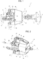
Figure 1 shows schematically a longitudinal view in elevation of a motion transmission device between a first and a second component with a force limiter function, made according to the invention and applied to a vehicle lighting device, illustrated only partially and schematically, and partially in longitudinal cross-section; -
Figure 2 schematically shows a three-quarter forward perspective view of the motion transmission device with force limiter function inFigure 1 ; -
Figure 3 shows, on a magnified scale, an elevation and longitudinal section view of the motion transmission device with force limiter function shown inFigure 2 ; -
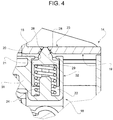
Figure 4 illustrates, in a further enlarged scale and schematically, a detail ofFigure 3 ; -
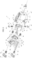
Figure 5 shows an exploded and three-quarter forward perspective view of the motion transmission device with force limiter function according to the invention; and -
Figures 6 and7 show the same cross-section view ofFigure 3 in two different working positions of the motion transmission device with force limiter function according to the invention. - With reference to
Figure 1 ,reference numeral 1 globally denotes a front headlamp for motor vehicles, configured to be fixed in a known manner, not illustrated for the sake of simplicity, to the chassis of a vehicle (also known and not illustrated). - The
lighting device 1 comprises ahousing 2, generally cup-shaped, alight source 3, areflector 4 and alens 5, either clear (i.e. not altering a light beam L produced by the light source 3) or optically active, which closes thehousing 2 at the front. - In order to direct the light beam L, simply to compensate for changes in the payload (passengers and/or luggage) of the vehicle (trim adjustment) or/and for example, to make the light beam L follow the bends made by the vehicle (adaptive lighting function), the
reflector 4 or, if absent, directly thelight source 3, can be rotated vertically and/or horizontally by means of anadjustment device 6, known in its general structure, comprising an electric motor oractuator 7, a linearmotion transmission device 8 from the motor/actuator 7 to the reflector 4 (or directly to the light source 3) and amanual trim adjuster 9, known and illustrated only schematically by dotted lines by a block, for simplicity. - More generally, the
motion transmission device 8 is used to transmit a linear motion between a first component (in the example shown, consisting of the motor/actuator 7) and a second component, the orientation/trim of which must be varied, in the example shown, consisting of thereflector 4, but more generally also consisting oflight source 3 alone. - According to the invention, the
transmission device 8 is designed with a force limiter function to protect the first component or motor/actuator 7 from any overloads that could damage it. - For this purpose, the transmission device 8 (
Figure 2 ) comprises asupport 10 for fixedly receiving thefirst component 7, anoutput shaft 11 of the first component,such output shaft 11 being axially mobile with respect to thesupport 10, afirst shaft 12, configured to be constrained in use to the second component 4 (or 3), and amechanical connection device 13 between the axiallymobile output shaft 11 and thefirst shaft 12. - According to the invention, the
mechanical connection device 13 comprises a cup-shaped body 14, in the example shown, delimited by acylindrical side wall 15 and coupled relatively slidingly to thesupport 10, parallel to theoutput shaft 11 and coaxially thereto, by means of at least a pair oflateral guides 16 attached to thesupport 10 and from which they protrude axially in a cantilever manner towards the cup-shaped body 14 which, according to one aspect of the invention, is fixed to thefirst shaft 12. - The
mechanical connection device 13 further comprises a bushing 18 mounted inside the cup-shaped body 14, arranged coaxial to the cup-shaped body 14 and housed relatively slidingly with respect thereto, said bushing 18 being axially integral, in any known manner, to theoutput shaft 11, so as to move integrally therewith. - The
side wall 15 of the cup-shaped body 14 is provided at one of its radially internal lateral surfaces 19 (Figure 4 ), with at least one pair of opposite radial holes 20 (which in the example shown are through holes, but which may also be blind), saidradial holes 20 being preferably conical in shape. - The
lateral surface 19 also cooperates with thebushing 18, in the example shown in contact therewith, and is preferably cylindrically symmetrical. - The
mechanical connection device 13 further comprises at least one pair ofopposite pegs 21 housed so as to slide in respectiveradial seats 22 of the bushing 18 (Figures 4 and5 ) made therein as far as through a radially externallateral wall 23 of thebushing 18. - The
radial seats 22 also housefirst springs 24 cooperating with thepegs 21. - The
springs 24 and theradial seats 22 are configured to make thepegs 21 selectively assume an extracted position (Figure 3 ) and a retracted position (Figures 6 and7 ). - In the extracted position of the
pegs 21, afirst end 25 of thepegs 21 protrudes radially cantilevered from thebushing 18 to engage theradial holes 20 of the cup-shaped body 14 and thus fix the cup-shaped body 14 to thebushing 18. - In the retracted position, the
first end 25 of the pegs is at least partially housed in a concealed fashion in theradial seats 20 against the action of thefirst springs 24 so as not to engage theradial holes 20 of the cup-shapedbody 14. - In order to facilitate the introduction of the
pegs 21 into theseats 22 and to prevent their accidental release, the pegs 21 (Figure 5 ) andseats 20 have bayonet couplings. - The
mechanical connection device 13 lastly comprisessecond springs 26, packed between thesupport 10 and the cup-shaped body 14 and between thesupport 10 and respective shoulder elements 27 (Figure 5 ), which are fixed to the cup-shaped body 14 and are arranged, with respect to thesupport 10, on the side opposite to the cup-shaped body 14. - According to another important aspect of the invention, the
first ends 25 of thepegs 21 are delimited by respective surfaces 28 (Figure 4 ) arranged obliquely with respect to an axis of symmetry A of theoutput shaft 11 and thebushing 18, in the non-limiting example illustrated defined by conical surfaces coaxial with thepegs 21. - The oblique (conical)
surfaces 28 are configured to cooperate with a perimeter edge 29 (Figure 4 ), also conical in the non-limiting example shown, of theradial holes 20 to push thepegs 21 towards the retracted position, against the action of thefirst springs 24, as a result of any axial stress F (Figures 6 and7 ) applied in use to thefirst shaft 12 and exceeding a pre-set threshold value, for example calculated during the design phase, so that in the retracted position of thepegs 21 thebushing 18 is no longer axially constrained to the cup-shaped body 14 and is consequently free to move axially with respect to the cup-shaped body 14. For the same reason, thesupport 10 is also free to move in relation to the cup-shaped body 14 against the action of thesprings 26, together (but not necessarily of the same magnitude) with thebushing 18. - The
mechanical connection device 13 further comprises asecond shaft 29 configured to couple integrally, on one side, with theoutput shaft 11 of thefirst component 7 and, on the other side, with thebushing 18. - According to one aspect of the invention, the
shaft 29 is connected to thebushing 18 by aball joint 30, preferably designed to allow a snap connection with theshaft 29. - According to a preferred embodiment of the invention, the
bushing 18 comprises: an annular or cup-shaped drum 31, preferably cylindrical, which has afirst end 32 facing thefirst shaft 12 and provided withradial seats 22 for thepegs 21 and thesprings 24; acover 33 for closing asecond end 34 of thedrum 31, opposite theend 32 and open towards thesupport 10; and a spherical joint 35 (Figure 5 ), which fixedly receives theoutput shaft 11 and cooperates in contact with a first innerlateral surface 36 of thedrum 31. - The
cover 33 is provided with ahole 37 for receiving theoutput shaft 11 through it as far as into thedrum 31 and thespherical joint 35 is axially blocked inside thedrum 31 by thecover 33. - The
output shaft 11 is coupled, according to the preferred embodiment shown by way of a non-limiting example, integral with thesecond shaft 29, which is arranged coaxial with it and also housed inside thedrum 31. - The
shaft 29 in turn couples to thespherical joint 35 radially inside thereof by means of theball joint 30, which comprises aspherical head 38 made in one piece with theshaft 29 at a first end thereof opposite theoutput shaft 11, and aspherical receiving element 39 for thespherical head 38, made in one piece with thespherical joint 35 and extending axially cantilevered towards thefirst end 32 of thedrum 31, with which it couples in contact with a second innerlateral surface 40 of thedrum 31 by means of an outer lateral surface thereof, of a spherical shape. - The
shaft 12 is preferably made in one piece with the cup-shaped body 14, coaxially with theoutput shaft 11, and extends axially cantilevered from abottom wall 41 of the cup-shaped body 14, externally thereto and on the opposite side of thebushing 18. - In addition, the
shaft 12 is preferably provided at one free end with a sphericaljoint coupling element 42 to thesecond component - In order to allow an easy, simple and effective assembly and a reliable operation of the
springs 26, thesupport 10 is provided radially cantilevered and radially externally with at least one pair of oppositefirst lugs 43, each of which is delimited (shown only inFigure 5 ) by afirst face 44 facing the cup-shaped body 14 and by asecond face 45 facing the side opposite to the cup-shaped body 14. - The
faces first pin 46 and asecond pin 47, opposite and coaxial. - The
pins output shaft 11 and of the bushing 18 and partially supportingcantilevered springs 26, which are helical springs each fitted on a respective first orsecond pin second faces lugs 43. - The cup-
shaped body 14 is provided at thefirst lugs 43 of thesupport 10 withsecond lugs 48 facing thelugs 43. - Respective pairs of
straight longerons 49 protrude cantilevered from thelugs 48, parallel to thepins Figure 5 ). - Between each pair of longerons 49 a respective radially
outer end 50 of alug 43 provided with a respectivefirst pin 46 andsecond pin 47 is axially slidingly inserted, which are also arranged between the pair oflongerons 49 together with a pair ofsecond springs 26, each fitted on a first orsecond pin - The
shoulder elements 27 preferably consist of plates, each snap-coupled to respective free ends 51 of a pair of longerons 50 (Figure 5 ). - The
plates 27 and thelugs 48 are preferably provided one towards the other withcantilevered sleeves 52 coaxial with thepins springs 26 opposite thefirst lugs 43 are inserted. - The
sleeves 52 are also configured to cooperate with the radially outer ends 50 of thelugs 43 to serve as axial end stop elements for thesupport 10 when thepegs 21 are in the retracted position. - Preferably, to facilitate assembly, the cup-shaped
body 14 is made up of two elements consisting of anannular element 53 coupled frontally to a cup-shapedelement 54 and connected integrally together by means of detachable connection members, preferably screws 55. - The cup-shaped
element 54 is the one with the radial holes 20 and both theannular element 53 and cup-shapedelement 54 are coaxial to each other and configured to slidingly receive thebushing 18 inside them. - From the description above it is clear that the
transmission device 13 is specifically configured to be housed inside avehicle lighting device 1 to connect an electric motor oractuator 7 with areflector 4 orlight source 3, to vary its orientation. - For this purpose, the
support 10 is also provided, on the side opposite the lateral guides 16, with a pair oflateral pads 56, configured to support theentire transmission device 13 inside thelighting device 1 and specifically to couple withelements 57, illustrated merely schematically and by dashed lines inFigure 1 , of the manualtrim adjuster 9. - The invention therefore lastly also relates to a vehicle comprising a
lighting device 1, headlamp or rear light provided with atransmission device 13 as described, for connecting together an electric motor oractuator 7 with areflector 4 orlight source 3 in order to vary the orientation thereof. - Owing to the
transmission device 13 as described, it is clear that the lighting device equipped with it is protected from damage not only in the case of jamming of the lighting element, but also in the case of projectors without an external lens as a result of vandalism or in any other case of excessive force applied to the lighting elements. - Consequently, all the purposes of the invention are achieved.
Claims (10)
- A motion transmission device (8) for transmitting a linear motion between a first (7) and a second (4) component with a force limiter function, in particular applicable to a lighting device (1) for vehicles, comprising a support (10) for fixedly receiving the first component, an output shaft (11) of the first component, axially mobile with respect to the support, a first shaft (12), configured to be constrained in use to the second component, and a mechanical connection device (13) between the axially mobile output shaft and the first shaft; characterized in that the mechanical connection device (13) comprises:i)- a cup-shaped body (14), slidably coupled with respect to the support in a direction parallel to the output shaft and coaxially thereto by means of at least one pair of lateral guides (16) fixed to the support; the cup-shaped body being fixed with respect to the first shaft (12);ii)- a bushing (18), mounted inside the cup-shaped body, which is coaxial and slidable with respect thereto, the bushing being axially constrained in a fixed way to the output shaft (11) so as to move integrally therewith;iii)- at least one pair of radial holes (20), made in a radially inner lateral surface (19) of the cup-shaped body, said lateral surface cooperating with the bushing (18);iv)- at least one pair of opposed pegs (21), housed so that they can slide within respective radial seats (22) of the bushing, which are provided within said bushing, and until they pass through a radially outer lateral wall (23) of the bushing, the radial seats further housing first springs (24) which cooperate with the pegs, the first springs and the radial seats being configured to cause the pegs to selectively assume an extracted position, in which a first end (25) of the pegs radially projects in a cantilever fashion from the bushing to engage said radial holes (20) of the cup-shaped body and fix the cup-shaped body to the bushing, and a retracted position, in which the first end (25) of the pegs is at least partially housed in a concealed fashion in the radial seats against the action of the first springs so as not to engage the radial holes of the cup-shaped body; andv)- second springs (26), packed between the support (10) and the cup-shaped body (14) and between the support and respective shoulder elements (27), which are fixed to the cup-shaped body and are arranged, with respect to the support, on the side opposite to the cup-shaped body;vi)- the first ends (25) of the pegs being delimited by respective surfaces (28), arranged obliquely with respect to an axis of symmetry (A) of the output shaft and of the bushing and configured to cooperate with a perimetral edge of said radial holes (20) so as to push the pegs towards the retracted position, against the action of the first springs, as a result of any axial load applied in use to the first shaft (12) that exceeds a threshold value, so that, in the retracted position of the pegs, the bushing (18) is no longer axially constrained to the cup-shaped body and is free to translate axially with respect thereto together with the support.
- The transmission device according to Claim 1, characterized in that the mechanical connection device further comprises a second shaft (29) configured to fixedly couple, on one side, to the output shaft (11) of the first component and, on the opposite side, to said bushing (18); the second shaft connecting to the bushing by means of a ball joint (30) and, preferably, by snap action.
- The transmission device according to Claim 1 or 2, characterized in that said bushing (18) comprises: an annular or cup-shaped drum (31), preferably cylindrical, which has a first end (32) facing the first shaft and provided with said radial seats (22) for the pegs and for the first springs; a cover (33) for closing a second end (34) of the drum, which is opposite to the first end and is open towards the support, the cover (33) being provided with a hole (37) for receiving the output shaft through it as far as into the drum (31); and a spherical joint (35), which fixedly receives the output shaft and cooperates in contact with a first inner lateral surface (36) of the drum, the spherical joint being axially blocked inside the drum by said cover.
- The transmission device according to Claim 3, characterized in that the output shaft (11) is fixedly coupled to a second shaft (29) coaxial therewith and housed within the drum, said second shaft is coupled to the spherical joint radially inside the latter by means of a ball joint (30) comprising a spherical head (38), which is made integrally of a single piece with the second shaft at a first end thereof opposite to the output shaft, and a spherical reception element (39) for receiving the spherical head, which is made integrally of a single piece with the spherical joint and extends axially in a cantilever fashion towards the first end of the drum, to which it couples in contact with a second inner lateral surface (40) of the drum by means of an outer lateral surface thereof having a spherical shape.
- The transmission device according to any one of the preceding claims, characterized in that the first shaft (12) is made integrally in a single piece with the cup-shaped body (14), coaxially with respect to the output shaft, and extends axially in a cantilever fashion from a bottom wall (41) of the cup-shaped body, externally thereto and on the opposite side of said bushing; the first shaft preferably being provided, at a free end thereof, with a spherical joint coupling element (42) for coupling to the second component so as to receive loads therefrom.
- The transmission device according to any one of the preceding claims, characterized in that the support (10) is provided, radially in a cantilever fashion and radially on the outside of at least one pair of first opposite lugs (43), each of which is delimited by a first face (44) facing the cup-shaped body and by a second face (45) facing on the side opposite to the cup-shaped body, the first and second faces being axially provided, in a cantilever fashion, with first pins (46) and second pins (47), respectively, which are opposite and coaxial to each other; said first and second pins (46, 47) being arranged parallel to the axis of symmetry of the output shaft and of the bushing and partially supporting in a cantilever fashion said second springs (26), which are helical springs each fitted on a respective first pin or second pin and are coupled in contact against the first and the second faces of said first lugs (43).
- The transmission device according to Claim 6, characterized in that the cup-shaped body (14) is provided, at the first lugs (43) of the support (10), with second lugs (48), which face the first lugs and from which respective pairs of rectilinear longerons (49) project in a cantilever fashion, in a direction parallel to said first and second pins (46, 47) and towards the support; between each pair of said longerons there being inserted in an axially slidable way a respective radially outer end (50) of a first lug (43) provided with a respective first pin (46) and second pin (47), which are also arranged between said pair of longerons (50) together with a pair of second springs (26), which are each fitted on a first pin or second pin; said shoulder elements (27) consisting of plates, each coupled by snap action to respective free ends (51) of a pair of said longerons; said plates and said second lugs being provided, towards one another, with cantilever sleeves (52), which are coaxial with the first and second pins and inserted within which are respective ends of the second springs (26) opposite to the first lugs; said sleeves (52) being configured to cooperate with said radially outer ends (50) of the first lugs to function as axial end-of-stroke elements for the support (10) when said pegs are in the retracted position.
- The transmission device according to any one of the preceding claims, characterized in that the cup-shaped body (14) is divided into two elements, which consist of an annular element (53) coupled frontally to a cup-shaped element (54) and are fixedly connected together by means of removable connection members (55), preferably screws; the cup-shaped element (54) being provided with said radial holes (20), and both the annular element and the cup-shaped element being coaxial to each other and configured to slidably receive said bushing (18) inside them.
- The transmission device according to any one of the preceding claims, characterized in that it is configured to be housed within a lighting device (1) for vehicles for connecting an electric motor or actuator (7) with a reflector (4) or light source (3) so as to vary the orientation thereof; said support (10) being provided, on opposite sides of said at least one pair of lateral guides (16), with a pair of lateral pads (56) configured to support the entire transmission device within the lighting device.
- A vehicle (1) comprising a lighting device, headlamp or rear light provided with a transmission device according to one of the preceding claims, for connecting together an electric motor or actuator (7) with a reflector (4) or light source (3) in order to vary the orientation thereof.
Applications Claiming Priority (1)
| Application Number | Priority Date | Filing Date | Title |
|---|---|---|---|
| IT102019000001797A IT201900001797A1 (en) | 2019-02-07 | 2019-02-07 | DEVICE FOR TRANSMISSION OF MOTION BETWEEN A FIRST AND A SECOND COMPONENT WITH A FORCE LIMITER FUNCTION, IN PARTICULAR APPLICABLE TO A LIGHTING DEVICE FOR VEHICLES |
Publications (2)
| Publication Number | Publication Date |
|---|---|
| EP3693217A1 EP3693217A1 (en) | 2020-08-12 |
| EP3693217B1 true EP3693217B1 (en) | 2021-08-04 |
Family
ID=66380043
Family Applications (1)
| Application Number | Title | Priority Date | Filing Date |
|---|---|---|---|
| EP20156226.1A Active EP3693217B1 (en) | 2019-02-07 | 2020-02-07 | Linear motion transmission device between a first and a second component with a force limiter function, in particular applicable to a lighting device for vehicles |
Country Status (3)
| Country | Link |
|---|---|
| EP (1) | EP3693217B1 (en) |
| CN (1) | CN111536486B (en) |
| IT (1) | IT201900001797A1 (en) |
Family Cites Families (9)
| Publication number | Priority date | Publication date | Assignee | Title |
|---|---|---|---|---|
| DE2241593A1 (en) * | 1972-08-24 | 1974-03-21 | Bosch Gmbh Robert | DEVICE FOR ADJUSTING THE LIGHT RANGE OF MOTOR VEHICLE HEADLIGHTS |
| DE2803089A1 (en) * | 1978-01-25 | 1979-07-26 | Rau Swf Autozubehoer | DEVICE FOR ADJUSTING A MOVABLE ELEMENT |
| ITTO20030856A1 (en) * | 2003-10-31 | 2005-05-01 | Skf Ab | LINEAR SCREW SCREW ACTUATOR WITH A SAFETY RELEASE DEVICE. |
| ATE500093T1 (en) * | 2008-04-25 | 2011-03-15 | Hella Kgaa Hueck & Co | HEADLIGHTS FOR VEHICLES |
| FR2975057B1 (en) * | 2011-05-12 | 2015-04-17 | Aml Systems | CABLE RANGE CORRECTION FOR MOTOR VEHICLE PROJECTOR |
| US20120294028A1 (en) * | 2011-05-19 | 2012-11-22 | GM Global Technology Operations LLC | Ball socket with spring retention ring |
| AT515451B1 (en) * | 2014-03-10 | 2016-02-15 | Zizala Lichtsysteme Gmbh | Adjustment device for a vehicle headlight |
| EP3354969B1 (en) * | 2017-01-31 | 2021-05-26 | Marelli Automotive Lighting Italy S.p.A. | Lighting device for vehicles having rotating lighting modules |
| US10508701B2 (en) * | 2017-04-06 | 2019-12-17 | The Pullman Company | Vehicle suspension bushing assembly and method of assembling the same |
-
2019
- 2019-02-07 IT IT102019000001797A patent/IT201900001797A1/en unknown
-
2020
- 2020-02-06 CN CN202010081920.6A patent/CN111536486B/en active Active
- 2020-02-07 EP EP20156226.1A patent/EP3693217B1/en active Active
Also Published As
| Publication number | Publication date |
|---|---|
| IT201900001797A1 (en) | 2020-08-07 |
| CN111536486A (en) | 2020-08-14 |
| EP3693217A1 (en) | 2020-08-12 |
| CN111536486B (en) | 2025-03-07 |
Similar Documents
| Publication | Publication Date | Title |
|---|---|---|
| KR102362425B1 (en) | Child safety seat | |
| CN113840971B (en) | Furniture drive | |
| EP2666667B1 (en) | Vehicle seat scissors suspension with integrated stabilized isolator | |
| US5855047A (en) | Belt buckle with fastener fitting | |
| US9475416B2 (en) | Lockout mechanism for foldable head rest | |
| US4116538A (en) | Motor-car mirror adjustable about two perpendicular axes | |
| EP2805853B1 (en) | Folding rearview mirror for motor vehicles | |
| US5669107A (en) | Friction detent apparatus for seat accessory | |
| CA2784535C (en) | Chair with a pillar-mounted rocking mechanism | |
| CA2270846C (en) | Child safety seat | |
| US6578920B2 (en) | Vehicle seat having a seat proper of adjustable height | |
| KR19980701551A (en) | EXTERIOR MIRROR WITH SINGLE PIVOT POWER FOLD | |
| KR101530899B1 (en) | Length-adjustable exterior mirror adjustment means | |
| US20170232901A1 (en) | Folding Device for an Exterior Mirror | |
| WO2002081262A1 (en) | Extendable mirror with detent | |
| US7350931B1 (en) | Vehicular pivot mirror | |
| US8550224B2 (en) | Energy absorption system | |
| KR20140007460A (en) | Automatically switching clutch for a motor vehicle exterior mirror adjustment means | |
| US20080030885A1 (en) | Vehicle pivot mirror | |
| EP3693217A1 (en) | Linear motion transmission device between a first and a second component with a force limiter function, in particular applicable to a lighting device for vehicles | |
| GB2041188A (en) | Motor vehicle headlight | |
| US4057287A (en) | Sun shade for motor vehicle | |
| CN107428277B (en) | Device for variable fixing of vehicle seat headrests | |
| CN105599685B (en) | Rearview mirror assembly for motor vehicle | |
| US20170368996A1 (en) | Vehicle door mirror |
Legal Events
| Date | Code | Title | Description |
|---|---|---|---|
| PUAI | Public reference made under article 153(3) epc to a published international application that has entered the european phase |
Free format text: ORIGINAL CODE: 0009012 |
|
| STAA | Information on the status of an ep patent application or granted ep patent |
Free format text: STATUS: THE APPLICATION HAS BEEN PUBLISHED |
|
| AK | Designated contracting states |
Kind code of ref document: A1 Designated state(s): AL AT BE BG CH CY CZ DE DK EE ES FI FR GB GR HR HU IE IS IT LI LT LU LV MC MK MT NL NO PL PT RO RS SE SI SK SM TR |
|
| AX | Request for extension of the european patent |
Extension state: BA ME |
|
| STAA | Information on the status of an ep patent application or granted ep patent |
Free format text: STATUS: REQUEST FOR EXAMINATION WAS MADE |
|
| 17P | Request for examination filed |
Effective date: 20201223 |
|
| RBV | Designated contracting states (corrected) |
Designated state(s): AL AT BE BG CH CY CZ DE DK EE ES FI FR GB GR HR HU IE IS IT LI LT LU LV MC MK MT NL NO PL PT RO RS SE SI SK SM TR |
|
| GRAP | Despatch of communication of intention to grant a patent |
Free format text: ORIGINAL CODE: EPIDOSNIGR1 |
|
| STAA | Information on the status of an ep patent application or granted ep patent |
Free format text: STATUS: GRANT OF PATENT IS INTENDED |
|
| RIC1 | Information provided on ipc code assigned before grant |
Ipc: F16H 25/20 20060101ALI20210128BHEP Ipc: B60Q 1/076 20060101AFI20210128BHEP |
|
| INTG | Intention to grant announced |
Effective date: 20210303 |
|
| RIN1 | Information on inventor provided before grant (corrected) |
Inventor name: FALESSI, ALESSANDRO |
|
| GRAS | Grant fee paid |
Free format text: ORIGINAL CODE: EPIDOSNIGR3 |
|
| GRAA | (expected) grant |
Free format text: ORIGINAL CODE: 0009210 |
|
| STAA | Information on the status of an ep patent application or granted ep patent |
Free format text: STATUS: THE PATENT HAS BEEN GRANTED |
|
| AK | Designated contracting states |
Kind code of ref document: B1 Designated state(s): AL AT BE BG CH CY CZ DE DK EE ES FI FR GB GR HR HU IE IS IT LI LT LU LV MC MK MT NL NO PL PT RO RS SE SI SK SM TR |
|
| REG | Reference to a national code |
Ref country code: GB Ref legal event code: FG4D |
|
| REG | Reference to a national code |
Ref country code: AT Ref legal event code: REF Ref document number: 1416664 Country of ref document: AT Kind code of ref document: T Effective date: 20210815 |
|
| REG | Reference to a national code |
Ref country code: CH Ref legal event code: EP |
|
| REG | Reference to a national code |
Ref country code: DE Ref legal event code: R096 Ref document number: 602020000311 Country of ref document: DE |
|
| REG | Reference to a national code |
Ref country code: IE Ref legal event code: FG4D |
|
| REG | Reference to a national code |
Ref country code: LT Ref legal event code: MG9D |
|
| REG | Reference to a national code |
Ref country code: NL Ref legal event code: MP Effective date: 20210804 |
|
| REG | Reference to a national code |
Ref country code: AT Ref legal event code: MK05 Ref document number: 1416664 Country of ref document: AT Kind code of ref document: T Effective date: 20210804 |
|
| PG25 | Lapsed in a contracting state [announced via postgrant information from national office to epo] |
Ref country code: SE Free format text: LAPSE BECAUSE OF FAILURE TO SUBMIT A TRANSLATION OF THE DESCRIPTION OR TO PAY THE FEE WITHIN THE PRESCRIBED TIME-LIMIT Effective date: 20210804 Ref country code: RS Free format text: LAPSE BECAUSE OF FAILURE TO SUBMIT A TRANSLATION OF THE DESCRIPTION OR TO PAY THE FEE WITHIN THE PRESCRIBED TIME-LIMIT Effective date: 20210804 Ref country code: ES Free format text: LAPSE BECAUSE OF FAILURE TO SUBMIT A TRANSLATION OF THE DESCRIPTION OR TO PAY THE FEE WITHIN THE PRESCRIBED TIME-LIMIT Effective date: 20210804 Ref country code: FI Free format text: LAPSE BECAUSE OF FAILURE TO SUBMIT A TRANSLATION OF THE DESCRIPTION OR TO PAY THE FEE WITHIN THE PRESCRIBED TIME-LIMIT Effective date: 20210804 Ref country code: HR Free format text: LAPSE BECAUSE OF FAILURE TO SUBMIT A TRANSLATION OF THE DESCRIPTION OR TO PAY THE FEE WITHIN THE PRESCRIBED TIME-LIMIT Effective date: 20210804 Ref country code: PT Free format text: LAPSE BECAUSE OF FAILURE TO SUBMIT A TRANSLATION OF THE DESCRIPTION OR TO PAY THE FEE WITHIN THE PRESCRIBED TIME-LIMIT Effective date: 20211206 Ref country code: NO Free format text: LAPSE BECAUSE OF FAILURE TO SUBMIT A TRANSLATION OF THE DESCRIPTION OR TO PAY THE FEE WITHIN THE PRESCRIBED TIME-LIMIT Effective date: 20211104 Ref country code: AT Free format text: LAPSE BECAUSE OF FAILURE TO SUBMIT A TRANSLATION OF THE DESCRIPTION OR TO PAY THE FEE WITHIN THE PRESCRIBED TIME-LIMIT Effective date: 20210804 Ref country code: BG Free format text: LAPSE BECAUSE OF FAILURE TO SUBMIT A TRANSLATION OF THE DESCRIPTION OR TO PAY THE FEE WITHIN THE PRESCRIBED TIME-LIMIT Effective date: 20211104 Ref country code: LT Free format text: LAPSE BECAUSE OF FAILURE TO SUBMIT A TRANSLATION OF THE DESCRIPTION OR TO PAY THE FEE WITHIN THE PRESCRIBED TIME-LIMIT Effective date: 20210804 |
|
| PG25 | Lapsed in a contracting state [announced via postgrant information from national office to epo] |
Ref country code: PL Free format text: LAPSE BECAUSE OF FAILURE TO SUBMIT A TRANSLATION OF THE DESCRIPTION OR TO PAY THE FEE WITHIN THE PRESCRIBED TIME-LIMIT Effective date: 20210804 Ref country code: LV Free format text: LAPSE BECAUSE OF FAILURE TO SUBMIT A TRANSLATION OF THE DESCRIPTION OR TO PAY THE FEE WITHIN THE PRESCRIBED TIME-LIMIT Effective date: 20210804 Ref country code: GR Free format text: LAPSE BECAUSE OF FAILURE TO SUBMIT A TRANSLATION OF THE DESCRIPTION OR TO PAY THE FEE WITHIN THE PRESCRIBED TIME-LIMIT Effective date: 20211105 |
|
| PG25 | Lapsed in a contracting state [announced via postgrant information from national office to epo] |
Ref country code: NL Free format text: LAPSE BECAUSE OF FAILURE TO SUBMIT A TRANSLATION OF THE DESCRIPTION OR TO PAY THE FEE WITHIN THE PRESCRIBED TIME-LIMIT Effective date: 20210804 |
|
| PG25 | Lapsed in a contracting state [announced via postgrant information from national office to epo] |
Ref country code: DK Free format text: LAPSE BECAUSE OF FAILURE TO SUBMIT A TRANSLATION OF THE DESCRIPTION OR TO PAY THE FEE WITHIN THE PRESCRIBED TIME-LIMIT Effective date: 20210804 |
|
| REG | Reference to a national code |
Ref country code: DE Ref legal event code: R097 Ref document number: 602020000311 Country of ref document: DE |
|
| PG25 | Lapsed in a contracting state [announced via postgrant information from national office to epo] |
Ref country code: SM Free format text: LAPSE BECAUSE OF FAILURE TO SUBMIT A TRANSLATION OF THE DESCRIPTION OR TO PAY THE FEE WITHIN THE PRESCRIBED TIME-LIMIT Effective date: 20210804 Ref country code: SK Free format text: LAPSE BECAUSE OF FAILURE TO SUBMIT A TRANSLATION OF THE DESCRIPTION OR TO PAY THE FEE WITHIN THE PRESCRIBED TIME-LIMIT Effective date: 20210804 Ref country code: RO Free format text: LAPSE BECAUSE OF FAILURE TO SUBMIT A TRANSLATION OF THE DESCRIPTION OR TO PAY THE FEE WITHIN THE PRESCRIBED TIME-LIMIT Effective date: 20210804 Ref country code: EE Free format text: LAPSE BECAUSE OF FAILURE TO SUBMIT A TRANSLATION OF THE DESCRIPTION OR TO PAY THE FEE WITHIN THE PRESCRIBED TIME-LIMIT Effective date: 20210804 Ref country code: CZ Free format text: LAPSE BECAUSE OF FAILURE TO SUBMIT A TRANSLATION OF THE DESCRIPTION OR TO PAY THE FEE WITHIN THE PRESCRIBED TIME-LIMIT Effective date: 20210804 Ref country code: AL Free format text: LAPSE BECAUSE OF FAILURE TO SUBMIT A TRANSLATION OF THE DESCRIPTION OR TO PAY THE FEE WITHIN THE PRESCRIBED TIME-LIMIT Effective date: 20210804 |
|
| PLBE | No opposition filed within time limit |
Free format text: ORIGINAL CODE: 0009261 |
|
| STAA | Information on the status of an ep patent application or granted ep patent |
Free format text: STATUS: NO OPPOSITION FILED WITHIN TIME LIMIT |
|
| 26N | No opposition filed |
Effective date: 20220506 |
|
| PG25 | Lapsed in a contracting state [announced via postgrant information from national office to epo] |
Ref country code: SI Free format text: LAPSE BECAUSE OF FAILURE TO SUBMIT A TRANSLATION OF THE DESCRIPTION OR TO PAY THE FEE WITHIN THE PRESCRIBED TIME-LIMIT Effective date: 20210804 |
|
| PG25 | Lapsed in a contracting state [announced via postgrant information from national office to epo] |
Ref country code: MC Free format text: LAPSE BECAUSE OF FAILURE TO SUBMIT A TRANSLATION OF THE DESCRIPTION OR TO PAY THE FEE WITHIN THE PRESCRIBED TIME-LIMIT Effective date: 20210804 |
|
| REG | Reference to a national code |
Ref country code: BE Ref legal event code: MM Effective date: 20220228 |
|
| PG25 | Lapsed in a contracting state [announced via postgrant information from national office to epo] |
Ref country code: LU Free format text: LAPSE BECAUSE OF NON-PAYMENT OF DUE FEES Effective date: 20220207 |
|
| PG25 | Lapsed in a contracting state [announced via postgrant information from national office to epo] |
Ref country code: IE Free format text: LAPSE BECAUSE OF NON-PAYMENT OF DUE FEES Effective date: 20220207 |
|
| PG25 | Lapsed in a contracting state [announced via postgrant information from national office to epo] |
Ref country code: BE Free format text: LAPSE BECAUSE OF NON-PAYMENT OF DUE FEES Effective date: 20220228 |
|
| REG | Reference to a national code |
Ref country code: CH Ref legal event code: PL |
|
| PG25 | Lapsed in a contracting state [announced via postgrant information from national office to epo] |
Ref country code: LI Free format text: LAPSE BECAUSE OF NON-PAYMENT OF DUE FEES Effective date: 20230228 Ref country code: CH Free format text: LAPSE BECAUSE OF NON-PAYMENT OF DUE FEES Effective date: 20230228 |
|
| PG25 | Lapsed in a contracting state [announced via postgrant information from national office to epo] |
Ref country code: MK Free format text: LAPSE BECAUSE OF FAILURE TO SUBMIT A TRANSLATION OF THE DESCRIPTION OR TO PAY THE FEE WITHIN THE PRESCRIBED TIME-LIMIT Effective date: 20210804 Ref country code: CY Free format text: LAPSE BECAUSE OF FAILURE TO SUBMIT A TRANSLATION OF THE DESCRIPTION OR TO PAY THE FEE WITHIN THE PRESCRIBED TIME-LIMIT Effective date: 20210804 |
|
| PG25 | Lapsed in a contracting state [announced via postgrant information from national office to epo] |
Ref country code: HU Free format text: LAPSE BECAUSE OF FAILURE TO SUBMIT A TRANSLATION OF THE DESCRIPTION OR TO PAY THE FEE WITHIN THE PRESCRIBED TIME-LIMIT; INVALID AB INITIO Effective date: 20200207 |
|
| PG25 | Lapsed in a contracting state [announced via postgrant information from national office to epo] |
Ref country code: MT Free format text: LAPSE BECAUSE OF FAILURE TO SUBMIT A TRANSLATION OF THE DESCRIPTION OR TO PAY THE FEE WITHIN THE PRESCRIBED TIME-LIMIT Effective date: 20210804 |
|
| GBPC | Gb: european patent ceased through non-payment of renewal fee |
Effective date: 20240207 |
|
| PG25 | Lapsed in a contracting state [announced via postgrant information from national office to epo] |
Ref country code: GB Free format text: LAPSE BECAUSE OF NON-PAYMENT OF DUE FEES Effective date: 20240207 |
|
| PG25 | Lapsed in a contracting state [announced via postgrant information from national office to epo] |
Ref country code: GB Free format text: LAPSE BECAUSE OF NON-PAYMENT OF DUE FEES Effective date: 20240207 |
|
| PGFP | Annual fee paid to national office [announced via postgrant information from national office to epo] |
Ref country code: DE Payment date: 20260121 Year of fee payment: 7 |
|
| PGFP | Annual fee paid to national office [announced via postgrant information from national office to epo] |
Ref country code: IT Payment date: 20260121 Year of fee payment: 7 |
|
| PGFP | Annual fee paid to national office [announced via postgrant information from national office to epo] |
Ref country code: FR Payment date: 20260121 Year of fee payment: 7 |
|
| PGFP | Annual fee paid to national office [announced via postgrant information from national office to epo] |
Ref country code: TR Payment date: 20260126 Year of fee payment: 7 |