EP3693134B1 - Gripping tool for adjustable wheel balancing clamping tools - Google Patents
Gripping tool for adjustable wheel balancing clamping tools Download PDFInfo
- Publication number
- EP3693134B1 EP3693134B1 EP20156099.2A EP20156099A EP3693134B1 EP 3693134 B1 EP3693134 B1 EP 3693134B1 EP 20156099 A EP20156099 A EP 20156099A EP 3693134 B1 EP3693134 B1 EP 3693134B1
- Authority
- EP
- European Patent Office
- Prior art keywords
- annular body
- adjustable
- outer annular
- edge
- inner annular
- Prior art date
- Legal status (The legal status is an assumption and is not a legal conclusion. Google has not performed a legal analysis and makes no representation as to the accuracy of the status listed.)
- Active
Links
Images






Classifications
-
- B—PERFORMING OPERATIONS; TRANSPORTING
- B25—HAND TOOLS; PORTABLE POWER-DRIVEN TOOLS; MANIPULATORS
- B25B—TOOLS OR BENCH DEVICES NOT OTHERWISE PROVIDED FOR, FOR FASTENING, CONNECTING, DISENGAGING, OR HOLDING
- B25B5/00—Clamps
- B25B5/14—Clamps for work of special profile
-
- B—PERFORMING OPERATIONS; TRANSPORTING
- B60—VEHICLES IN GENERAL
- B60B—VEHICLE WHEELS; CASTORS; AXLES FOR WHEELS OR CASTORS; INCREASING WHEEL ADHESION
- B60B15/00—Wheels or wheel attachments designed for increasing traction
- B60B15/28—Wheel-ballasting weights; Their attachment
-
- B—PERFORMING OPERATIONS; TRANSPORTING
- B60—VEHICLES IN GENERAL
- B60B—VEHICLE WHEELS; CASTORS; AXLES FOR WHEELS OR CASTORS; INCREASING WHEEL ADHESION
- B60B3/00—Disc wheels, i.e. wheels with load-supporting disc body
- B60B3/14—Attaching disc body to hub ; Wheel adapters
Definitions
- the present invention relates generally to a grip system. More specifically, the present invention relates to a grip system for a wheel balancing clamping tool that can adjust to different bolt patterns.
- the wheel is flipped and the adjustable wheel balancing clamping tool is positioned against the back of the center bore wheel hub to correctly adjust the adjustable wheel balancing clamping tool according to the bolt pattern of the wheel. Then, the user uses one hand to mount the wheel on a wheel balancing machine, and the other hand to hold the adjustable wheel balancing clamping tool.
- An example of an existing adjustable wheel balancing clamping tool is D1 ( US20150069824 ) which discloses a wheel lug ring having an annular body with a cavity formed on one side having a plurality of lug wells in a registered positioning to engage around a plurality of lug nuts holding a wheel to an axle.
- the present invention addresses this issue by providing a gripping tool for the adjustable wheel balancing clamping tool according to claims 1 and 4.
- the present invention provides additional gripping surface area to the adjustable wheel balancing clamping tool that allows an individual to simultaneously adjust and hold the tool with one hand.
- the present invention provides the gripping tool for adjustable wheel balancing clamping tool, characterized in that the gripping tool comprises: a gripping body; an adjustable-bolt-pattern-adaptor attachment mechanism; the gripping body comprising an outer annular body, an inner annular body, and a connector ring; the inner annular body being concentrically positioned within the outer annular body; the connector ring being perimetrically connected the outer annular body and the inner annular body; a cross section between the outer annular body, the connector ring, and the inner annular body being a U-shaped cross section; the connector ring being terminally positioned to a first outer edge of the outer annular body and a first inner edge of the inner annular body; the adjustable-bolt-pattern-adaptor attachment mechanism being connected to the outer annular body and the inner annular body; the adjustable-bolt-pattern-adaptor attachment mechanism and the connector ring being oppositely oriented of each other about the outer annular body and the inner annular body; the adjustable-bolt-pattern-
- the present invention is a gripping tool for adjustable wheel balancing clamping tool so that the user is able to hold and adjust the adjustable wheel balancing clamping tool with only one hand. More specifically, the adjustable wheel balancing clamping tool enables the user to reliably mount a wheel on a wheel balancing machine in a desired orientation. To accomplish this, the adjustable wheel balancing clamping tool employs a stud adjustment system in order to change the orientation of the studs that engages with lug holes of the wheel. Generally, the user holds the adjustable wheel balancing clamping tool with one hand while the other hand is used to operate the stud adjustment system, which adjust the bolt pattern with respect to the wheel. However, the present invention functions as an accessory tool for the adjustable wheel balancing clamping tool so that the user can hold the adjustable wheel balancing clamping tool and operate the stud adjustment system with one hand.
- the present invention comprises a gripping body 1 and an adjustable-bolt-pattern-adaptor attachment mechanism 10 as shown in FIG. 1-2 and 6-7.
- the gripping body 1 provides ergonomic surface area so that the user can comfortably grasp the present invention.
- the gripping body 1 comprises an outer annular body 2, an inner annular body 6, and a connector ring 9 thus delineating ring shaped body.
- the inner annular body 6 is concentrically positioned within the outer annular body 2.
- the connector ring 9 is perimetrically connected the outer annular body 2 and the inner annular body 6 as the structural body between the inner annular body 6 and the outer annular body 2.
- the connector ring 9 is terminally positioned to a first outer edge 3 of the outer annular body 2 and a first inner edge 7 of the inner annular body 6 so that the connector ring 9 can be positioned flush with the inner annular body 6 and the outer annular body 2.
- the user can use their fingers to apply upward tension to the inner annular body 6 thus pressing the connector ring 9 against the user's palm.
- the user can user their palm to apply tension to the connector ring 9 thus pressing the inner annular body 6 towards the user's fingers.
- the user can position their thumb over the outer annular body 2 to operate the stud adjustment system so that the bolt pattern of the adjustable wheel balancing clamping tool can be adjusted.
- the adjustable-bolt-pattern-adaptor attachment mechanism 10 is connected to the outer annular body 2 and the inner annular body 6 and functions as the attachment mechanism 10 that secures the present invention to the adjustable wheel balancing clamping tool. Furthermore, the adjustable-bolt-pattern-adaptor attachment mechanism 10 and the connector ring 9 are oppositely oriented of each other about the outer annular body 2 and the inner annular body 6 so that the stud adjustment system can be independently operated from the gripping body 1.
- the adjustable-bolt-pattern-adaptor attachment mechanism 10 preferably comprises a plurality of fasteners 11 that is radially positioned in between the outer annular body 2 and the inner annular body 6.
- the plurality of fasteners 11 functions as the attachment bodies for the gripping body 1 so that the present invention can be removably mounted to the adjustable wheel balancing clamping tool.
- the plurality of fasteners 11 each comprises a supporting rib 12, a female fastening portion 13, and a male fastening portion 14.
- the supporting rib 12 is generally a rectangular body and terminally connected to the outer annular body 2, the inner annular body 6, and the connector ring 9.
- the female fastening portion 13 is generally cylindrical body and connected to the supporting rib 12 and oriented away from the connector ring 9. In other words, the female fastening portion 13 is integrated into the supporting rib 12 so that an opening of the female fastening portion 13 is oriented in the opposite direction in comparison to the connector ring 9.
- the male fastening portion 14 is removably engaged with the female fastening portion 13 in such a way that the male fastening portion 14 and the female fastening portion 13 can collectively compress a base plate of the adjustable wheel balancing clamping tool.
- the male fastening portion 14 and the female fastening portion 13 are threadedly interconnected to each other so that the user is able to easily interact with the male fastening portion 14 with standard tooling apparatus such as screwdrivers, ratchet wrenches, and impact drivers.
- the male fastening portion 14 is designed to traverse through a cavity of the base plate so that the male fastening portion 14 can threadedly interconnect with the female fastening portion 13.
- the adjustable-bolt-pattern-adaptor attachment mechanism 10 further comprises a plurality of structural ribs 15 in addition to the plurality of fasteners 11.
- the plurality of structural ribs 15 is terminally connected to the outer annular body 2, the inner annular body 6, and the connector ring 9 to improve the structural integrity of the gripping body 1.
- each of the plurality of structural ribs 15 is radially spaced within the plurality of fasteners 11 to further structurally strengthen the each of the plurality of fasteners 11.
- the present invention can eliminate any structural misalignment as the female fastening portion 13 of each of the plurality of fasteners 11 can concentrically align with the cavities of the base plate to receive the male fastening portion 14.
- the outer annular body 2 further comprises a second outer edge 4 and a lip section 5, and the inner annular body 6 further comprises a second inner edge 8.
- the second outer edge 4 and the first outer edge 3 are oppositely positioned of each other about the outer annular body 2, wherein the second outer edge 4 is preferably a free hanging edge.
- the second inner edge 8 and the first inner edge 7 are oppositely positioned of each other about the inner annular body 6, wherein the second inner edge 8 is preferably a free hanging edge.
- the supporting rib 12 is positioned flush to the second inner edge 8 so that the second inner edge 8 and the plurality of fasteners 11 can position flat against the base plate.
- the lip section 5 is delineated from the supporting rib 12 to the second outer edge 4 so that the lip section 5 can perimetrically encircle around the base plate thus providing a precise alignment between the gripping body 1 and the base plate. Resultantly, the user can stationary grasp the adjustable wheel balancing clamping tool via the plurality of fasteners 11 and the gripping body 1 and adjust the bolt pattern with respect to the corresponding wheel by only utilizing one hand.
- the gripping body 1 and the adjustable-bolt-pattern-adaptor attachment mechanism 10 are preferably configured as a single apparatus, in alternative embodiments of the present invention, the gripping body 1 and the adjustable-bolt-pattern-adaptor attachment mechanism 10 can be made as a plurality of segmented pieces as shown in FIG. 14 .
- the outer annular body 2, the inner annular body 6, the connector ring 9, and the adjustable-bolt-pattern-adaptor attachment mechanism 10 can be manufactured as separate components and assembled together.
- the gripping body 1 and the adjustable-bolt-pattern-adaptor attachment mechanism 10 can also be segmented into a plurality of radial sections as the general profile of the gripping body 1 is collectively configured through the plurality of radial sections.
- the present invention can be alternatively integrated into the base plate of the adjustable wheel balancing clamping tool.
- the adjustable-bolt-pattern-adaptor attachment mechanism 10 may comprise a base plate 16, a plurality of pin-receiving recesses 17, and a central bushing 18.
- the functionality of the present invention and the base plate 16 are integrated to each other as the general profile of the gripping body 1 and the base plate 16 are constructed as a singular body. More specifically, the base plate 16 is radially connected to the outer annular body 2 and the inner annular body 6 thus enclosing the internal space between the outer annular body 2 and the inner annular body 6.
- the base plate 16 is terminally connected to the second outer edge 4 and the second inner edge 8 thus providing a structural base to configure the stud adjustment system around the central bushing 18.
- the central bushing 18 is concentrically connected to the base plate 16 so that the central bushing 18 can be mounted to the wheel balancing machine.
- the plurality of pin-receiving recesses 17 traverses into the base plate 16 and is distributed around the central bushing 18. More specifically, a first base surface 161 of the base plate 16 is radially connected onto the second inner edge 8 as the first base surface 161 extends from the inner annular body 6 to the central bushing 18.
- a second base surface 162 of the base plate 16 is positioned flush with the second outer edge 4 as the second base surface 162 extends from the second outer edge 4 to the central bushing 18. Resultantly, the user can stationarily grasp the adjustable wheel balancing clamping tool via the outer annular body 2 and the inner annular body 6 with respect to the first base surface 161 so that the bolt pattern can be adjusted via the stud adjustment system that is positioned adjacent to the second base surface 162 by only utilizing one hand.
- the present invention can be alternatively integrated into the base plate of the adjustable wheel balancing clamping tool thus defining an alternative embodiment.
- the base plate is radially connected to the outer annular body 2.
- the base plate is terminally connected to the second outer edge 4 thus providing a structural base to configure the stud adjustment system the central bushing.
- the central bushing is concentrically connected to the base plate so that the central bushing can be mounted to the wheel balancing machine.
- the present invention can be alternatively integrated into the base plate of the adjustable wheel balancing clamping tool thus defining another alternative embodiment. More specifically, the base plate is radially connected to the inner annular body 6. The base plate is terminally connected to the second inner edge 8 thus providing a structural base to configure the stud adjustment system the central bushing. The central bushing is concentrically connected to the base plate so that the central bushing can be mounted to the wheel balancing machine.
Landscapes
- Engineering & Computer Science (AREA)
- Mechanical Engineering (AREA)
- Constituent Portions Of Griding Lathes, Driving, Sensing And Control (AREA)
- Manipulator (AREA)
Description
- The current application claims a priority to the
U.S. Provisional Patent application serial number 62/803,171 filed on February 08, 2019 - The present invention relates generally to a grip system. More specifically, the present invention relates to a grip system for a wheel balancing clamping tool that can adjust to different bolt patterns.
- Existing adjustable wheel balancing clamping tools that can adjust to different bolt patterns require two hands to operate, with one hand holding the tool and the other hand adjusting the bolt pattern of the tool with respect to the wheel. More specifically, the tool is adjusted to fit the specific bolt pattern of the wheel, by rotating one of the gears. Since the adjustable wheel balancing clamping tools require both hands to adjust for a new bolt pattern, the user does not have a free hand to stabilize the tool and/or the wheel, to be balanced, during the mounting process of the wheel to the balancing machine. Therefore, two steps are generally required for balancing a wheel with a new bolt pattern. First, the user must use both hands to hold and adjust the adjustable wheel balancing clamping tool to the correct bolt pattern according to the wheel. Generally, the wheel is flipped and the adjustable wheel balancing clamping tool is positioned against the back of the center bore wheel hub to correctly adjust the adjustable wheel balancing clamping tool according to the bolt pattern of the wheel. Then, the user uses one hand to mount the wheel on a wheel balancing machine, and the other hand to hold the adjustable wheel balancing clamping tool. An example of an existing adjustable wheel balancing clamping tool is D1 (
US20150069824 ) which discloses a wheel lug ring having an annular body with a cavity formed on one side having a plurality of lug wells in a registered positioning to engage around a plurality of lug nuts holding a wheel to an axle. - Document
US3143327A discloses an adapter unit for use with a wheel balancing apparatus having the technical characteristics of the preamble ofclaims - Clearly, there is a need for an improvement to adjustable wheel balancing clamping tools that allow individuals to hold and adjust the tool with one hand. Such improvement can combine the aforementioned two-step process into a one-step process thus saving time and money. The present invention addresses this issue by providing a gripping tool for the adjustable wheel balancing clamping tool according to
claims claims 2,3 and 5. -
-
FIG. 1 is a front perspective view of the gripping body of the present invention with the preferred attachment mechanism. -
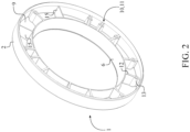
FIG. 2 is a rear perspective view of the gripping body of the present invention with the preferred attachment mechanism. -
FIG. 3 is a rear view of the present invention, showing the plane upon which a cross sectional view is taken shown inFIG. 4 . -
FIG. 4 is a cross section view thereof taken along line A-A ofFIG. 3 , showing the edges of the outer annular body and the inner annular body. -
FIG. 5 is a perspective exploded view of the present invention, wherein the preferred attachment mechanism is utilized to engage with the adjustable wheel balancing clamping tool. -
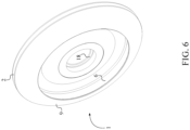
FIG. 6 is a front perspective view of the gripping body of the present invention, wherein the gripping body is integrated into the base plate of the adjustable wheel balancing clamping tool. -
FIG. 7 is a rear perspective view of the gripping body of the present invention, wherein the gripping body is integrated into the base plate of the adjustable wheel balancing clamping tool. -
FIG. 8 is a rear view of the present invention being integrated into the base plate of the adjustable wheel balancing clamping tool, showing the plane upon which a cross sectional view is taken shown inFIG. 9 . -
FIG. 9 is a cross section view thereof taken along line A-A ofFIG. 8 , showing the edges of the outer annular body and the inner annular body. -
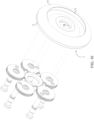
FIG. 10 is a perspective exploded view of the present invention being integrated into the base plate of the adjustable wheel balancing clamping tool, wherein the stud adjustment system is separated from the base plate. -
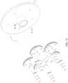
FIG. 11 is another perspective exploded view of the present invention being integrated into the base plate of the adjustable wheel balancing clamping tool, wherein the stud adjustment system is separated from the base plate. -
FIG. 12 is a perspective exploded view of alternative embodiment of the present invention as the base plate of the adjustable wheel balancing clamping tool and the gripping tool are being integrated into each other, wherein the stud adjustment system is separated from the base plate. -
FIG. 13 is a perspective exploded view of alternative embodiment of the present invention as the base plate of the adjustable wheel balancing clamping tool and the gripping tool are being integrated into each other, wherein the stud adjustment system is separated from the base plate. -
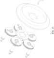
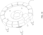
FIG. 14 is a perspective exploded view of alternative embodiment of the present invention, wherein the gripping body and the adjustable-bolt-pattern-adaptor attachment mechanism are a plurality of segmented pieces. - All illustrations of the drawings are for the purpose of describing selected versions of the present invention and are not intended to limit the scope of the present invention, which is disclosed in the appended claims.
- The present invention is a gripping tool for adjustable wheel balancing clamping tool so that the user is able to hold and adjust the adjustable wheel balancing clamping tool with only one hand. More specifically, the adjustable wheel balancing clamping tool enables the user to reliably mount a wheel on a wheel balancing machine in a desired orientation. To accomplish this, the adjustable wheel balancing clamping tool employs a stud adjustment system in order to change the orientation of the studs that engages with lug holes of the wheel. Generally, the user holds the adjustable wheel balancing clamping tool with one hand while the other hand is used to operate the stud adjustment system, which adjust the bolt pattern with respect to the wheel. However, the present invention functions as an accessory tool for the adjustable wheel balancing clamping tool so that the user can hold the adjustable wheel balancing clamping tool and operate the stud adjustment system with one hand.
- The present invention comprises a
gripping body 1 and an adjustable-bolt-pattern-adaptor attachment mechanism 10 as shown inFIG. 1-2 and 6-7. The grippingbody 1 provides ergonomic surface area so that the user can comfortably grasp the present invention. The grippingbody 1 comprises an outerannular body 2, an innerannular body 6, and aconnector ring 9 thus delineating ring shaped body. In reference to the general configuration of the present invention, the innerannular body 6 is concentrically positioned within the outerannular body 2. Theconnector ring 9 is perimetrically connected the outerannular body 2 and the innerannular body 6 as the structural body between the innerannular body 6 and the outerannular body 2. Theconnector ring 9 is terminally positioned to a first outer edge 3 of the outerannular body 2 and a first inner edge 7 of the innerannular body 6 so that theconnector ring 9 can be positioned flush with the innerannular body 6 and the outerannular body 2. When the present invention is secured within the user's hand, the user can use their fingers to apply upward tension to the innerannular body 6 thus pressing theconnector ring 9 against the user's palm. Simultaneously, the user can user their palm to apply tension to theconnector ring 9 thus pressing the innerannular body 6 towards the user's fingers. As a result, the user can position their thumb over the outerannular body 2 to operate the stud adjustment system so that the bolt pattern of the adjustable wheel balancing clamping tool can be adjusted. The adjustable-bolt-pattern-adaptor attachment mechanism 10 is connected to the outerannular body 2 and the innerannular body 6 and functions as the attachment mechanism 10 that secures the present invention to the adjustable wheel balancing clamping tool. Furthermore, the adjustable-bolt-pattern-adaptor attachment mechanism 10 and theconnector ring 9 are oppositely oriented of each other about the outerannular body 2 and the innerannular body 6 so that the stud adjustment system can be independently operated from the grippingbody 1. - In reference to
FIG. 2-3 , the adjustable-bolt-pattern-adaptor attachment mechanism 10 preferably comprises a plurality of fasteners 11 that is radially positioned in between the outerannular body 2 and the innerannular body 6. The plurality of fasteners 11 functions as the attachment bodies for the grippingbody 1 so that the present invention can be removably mounted to the adjustable wheel balancing clamping tool. - In reference to
FIG. 2-3 andFIG. 5 , the plurality of fasteners 11 each comprises a supportingrib 12, afemale fastening portion 13, and amale fastening portion 14. More specifically, the supportingrib 12 is generally a rectangular body and terminally connected to the outerannular body 2, the innerannular body 6, and theconnector ring 9. As a result, the supportingrib 12 is able to firmly secure to the grippingbody 1 with three different connection points. Thefemale fastening portion 13 is generally cylindrical body and connected to the supportingrib 12 and oriented away from theconnector ring 9. In other words, thefemale fastening portion 13 is integrated into the supportingrib 12 so that an opening of thefemale fastening portion 13 is oriented in the opposite direction in comparison to theconnector ring 9. Themale fastening portion 14 is removably engaged with thefemale fastening portion 13 in such a way that themale fastening portion 14 and thefemale fastening portion 13 can collectively compress a base plate of the adjustable wheel balancing clamping tool. Preferably, themale fastening portion 14 and thefemale fastening portion 13 are threadedly interconnected to each other so that the user is able to easily interact with themale fastening portion 14 with standard tooling apparatus such as screwdrivers, ratchet wrenches, and impact drivers. More specifically, themale fastening portion 14 is designed to traverse through a cavity of the base plate so that themale fastening portion 14 can threadedly interconnect with thefemale fastening portion 13. - In reference to
FIG. 3 , the adjustable-bolt-pattern-adaptor attachment mechanism 10 further comprises a plurality ofstructural ribs 15 in addition to the plurality of fasteners 11. The plurality ofstructural ribs 15 is terminally connected to the outerannular body 2, the innerannular body 6, and theconnector ring 9 to improve the structural integrity of the grippingbody 1. Furthermore, each of the plurality ofstructural ribs 15 is radially spaced within the plurality of fasteners 11 to further structurally strengthen the each of the plurality of fasteners 11. As a result, the present invention can eliminate any structural misalignment as thefemale fastening portion 13 of each of the plurality of fasteners 11 can concentrically align with the cavities of the base plate to receive themale fastening portion 14. - In reference to
FIG. 4 , the outerannular body 2 further comprises a secondouter edge 4 and a lip section 5, and the innerannular body 6 further comprises a secondinner edge 8. The secondouter edge 4 and the first outer edge 3 are oppositely positioned of each other about the outerannular body 2, wherein the secondouter edge 4 is preferably a free hanging edge. The secondinner edge 8 and the first inner edge 7 are oppositely positioned of each other about the innerannular body 6, wherein the secondinner edge 8 is preferably a free hanging edge. Furthermore, the supportingrib 12 is positioned flush to the secondinner edge 8 so that the secondinner edge 8 and the plurality of fasteners 11 can position flat against the base plate. The lip section 5 is delineated from the supportingrib 12 to the secondouter edge 4 so that the lip section 5 can perimetrically encircle around the base plate thus providing a precise alignment between thegripping body 1 and the base plate. Resultantly, the user can stationary grasp the adjustable wheel balancing clamping tool via the plurality of fasteners 11 and thegripping body 1 and adjust the bolt pattern with respect to the corresponding wheel by only utilizing one hand. - Even though the
gripping body 1 and the adjustable-bolt-pattern-adaptor attachment mechanism 10 are preferably configured as a single apparatus, in alternative embodiments of the present invention, thegripping body 1 and the adjustable-bolt-pattern-adaptor attachment mechanism 10 can be made as a plurality of segmented pieces as shown inFIG. 14 . In reference to an exemplary embodiment, the outerannular body 2, the innerannular body 6, theconnector ring 9, and the adjustable-bolt-pattern-adaptor attachment mechanism 10 can be manufactured as separate components and assembled together. In reference to another exemplary embodiment, thegripping body 1 and the adjustable-bolt-pattern-adaptor attachment mechanism 10 can also be segmented into a plurality of radial sections as the general profile of thegripping body 1 is collectively configured through the plurality of radial sections. - In reference to
FIG. 6-11 , the present invention can be alternatively integrated into the base plate of the adjustable wheel balancing clamping tool. Thus, the adjustable-bolt-pattern-adaptor attachment mechanism 10 may comprise a base plate 16, a plurality of pin-receiving recesses 17, and acentral bushing 18. In other words, the functionality of the present invention and the base plate 16 are integrated to each other as the general profile of thegripping body 1 and the base plate 16 are constructed as a singular body. More specifically, the base plate 16 is radially connected to the outerannular body 2 and the innerannular body 6 thus enclosing the internal space between the outerannular body 2 and the innerannular body 6. The base plate 16 is terminally connected to the secondouter edge 4 and the secondinner edge 8 thus providing a structural base to configure the stud adjustment system around thecentral bushing 18. Thecentral bushing 18 is concentrically connected to the base plate 16 so that thecentral bushing 18 can be mounted to the wheel balancing machine. The plurality of pin-receiving recesses 17 traverses into the base plate 16 and is distributed around thecentral bushing 18. More specifically, afirst base surface 161 of the base plate 16 is radially connected onto the secondinner edge 8 as thefirst base surface 161 extends from the innerannular body 6 to thecentral bushing 18. Asecond base surface 162 of the base plate 16 is positioned flush with the secondouter edge 4 as thesecond base surface 162 extends from the secondouter edge 4 to thecentral bushing 18. Resultantly, the user can stationarily grasp the adjustable wheel balancing clamping tool via the outerannular body 2 and the innerannular body 6 with respect to thefirst base surface 161 so that the bolt pattern can be adjusted via the stud adjustment system that is positioned adjacent to thesecond base surface 162 by only utilizing one hand. - In reference to
FIG. 12 , the present invention can be alternatively integrated into the base plate of the adjustable wheel balancing clamping tool thus defining an alternative embodiment. More specifically, the base plate is radially connected to the outerannular body 2. The base plate is terminally connected to the secondouter edge 4 thus providing a structural base to configure the stud adjustment system the central bushing. The central bushing is concentrically connected to the base plate so that the central bushing can be mounted to the wheel balancing machine. - In reference to
FIG. 13 , the present invention can be alternatively integrated into the base plate of the adjustable wheel balancing clamping tool thus defining another alternative embodiment. More specifically, the base plate is radially connected to the innerannular body 6. The base plate is terminally connected to the secondinner edge 8 thus providing a structural base to configure the stud adjustment system the central bushing. The central bushing is concentrically connected to the base plate so that the central bushing can be mounted to the wheel balancing machine. - Although the invention has been explained in relation to its preferred embodiment, it is to be understood that many other possible modifications and variations can be made without departing from the scope of the invention as hereinafter claimed.
Claims (5)
- A gripping tool for adjustable wheel balancing clamping tool, wherein the gripping tool comprises:a gripping body (1);an adjustable-bolt-pattern-adaptor attachment mechanism (10);the gripping body (1) comprising an outer annular body (2), an inner annular body (6), and a connector ring (9);the inner annular body (6) being concentrically positioned within the outer annular body (2);the connector ring (9) being perimetrically connected the outer annular body (2) and the inner annular body (6);a cross section between the outer annular body (2), the connector ring (9), and the inner annular body (6) being a U-shaped cross section;the connector ring (9) being terminally positioned to a first outer edge (3) of the outer annular body (2) and a first inner edge (7) of the inner annular body (6);the adjustable-bolt-pattern-adaptor attachment mechanism (10) being connected to the outer annular body (2) and the inner annular body (6);the adjustable-bolt-pattern-adaptor attachment mechanism (10) and the connector ring (9) being oppositely oriented of each other about the outer annular body (2) and the inner annular body (6);the adjustable-bolt-pattern-adaptor attachment mechanism (10) comprising a plurality of fasteners (11);the plurality of fasteners (11) each comprising a supporting rib (12), a female fastening portion (13), and a male fastening portion (14);the female fastening portion (13) being fixed in place along the supporting rib (12);the female fastening portion (13) being positioned offset from the outer annular body (2);the female fastening portion (13) being positioned offset from the inner annular body (6);the female fastening portion (13) being oriented away from the connector ring (9);the male fastening portion (14) being removably engaged with the female fastening portion (13); andthe male fastening portion (14) and the female fastening portion (13) being threadedly interconnected to each other,characterised in the plurality of fasteners (26) being radially positioned in between the outer annular body and the inner annular bodyand in the supporting rib (14) being terminally connected to the outer annular body, the inner annular body (6), and the connector ring (9);and in the female fastening portion (13) being connected to the supporting rib (12).
- The gripping tool as claimed in claim 1 comprising:the outer annular body (2) further comprising a second outer edge (4) and a lip section (5);the inner annular body (6) further comprising a second inner edge (8);the second outer edge (4) and the first outer edge (3) being oppositely positioned of each other about the outer annular body (2);the second inner edge (8) and the first inner edge (7) being oppositely positioned of each other about the inner annular body (6);the supporting rib (12) being positioned flush to the second inner edge (8); andthe lip section (5) being delineated from the supporting rib (12) to the second outer edge (4).
- The gripping tool as claimed in claim 1 comprising:the adjustable-bolt-pattern-adaptor attachment mechanism (10) comprising a plurality of structural ribs (15); andthe plurality of structural ribs (15) being terminally connected to the outer annular body (2), the inner annular body (6), and the connector ring (9); andthe plurality of structural ribs (15) being radially interspersed amongst the plurality of fasteners (11).
- A gripping tool for adjustable wheel balancing clamping tool, wherein the gripping tool comprises:a gripping body (1);an adjustable-bolt-pattern-adaptor attachment mechanism (10);the gripping body (1) comprising an outer annular body (2), an inner annular body (6), and a connector ring (9);the outer annular body (2) comprises a first outer edge (3) and a second outer edge (4);the inner annular body (6) comprises a first inner edge (7) and a second inner edge (8);the inner annular body (6) being concentrically positioned within the outer annular body (2);the connector ring (9) being perimetrically connected the outer annular body (2) and the inner annular body (6);the first outer edge (3) and the second outer edge (4) being oppositely positioned of each other about the outer annular body (2);the first inner edge (7) and the second inner edge (8) being oppositely positioned of each other about the inner annular body (6);the connector ring (9) being terminally positioned to the first outer edge (3) and the first inner edge (7);the adjustable-bolt-pattern-adaptor attachment mechanism (10) being connected to the outer annular body (2) and the inner annular body (6);the adjustable-bolt-pattern-adaptor attachment mechanism (10) comprising a base plate (16), a plurality of pin-receiving recesses (17), and a central bushing (18);the base plate (16) being radially connected to the outer annular body (2) and the inner annular body (6);the base plate (16) being terminally connected to the second outer edge (4) and the second inner edge (8);the central bushing (18) being concentrically connected to the base platecharacterised in that the adjustable-bolt-pattern-adaptor attachment mechanism and the connector ring (9) being oppositely oriented of each other about the outer annular body (2) and the inner annular body (6);and in thata protruding shape delineated between the outer annular body (2), the connector ring (9), and the inner annular body (6) being oriented in an opposite direction than the central bushing (18);the plurality of pin-receiving recesses (17) traversing into the base plate (16);the plurality of pin-receiving recesses (17) being angularly positioned offset from the protruding shape delineated between the outer annular body (2), the connector ring (9), and the inner annular body (6);the plurality of pin-receiving recesses (17) being angularly positioned adjacent to the central bushing (18); andthe plurality of pin-receiving recesses (17) being distributed around the central bushing (18).
- The gripping tool for adjustable wheel balancing clamping tool as claimed in claim 4 comprising:the base plate (16) comprising a first base surface (161) and a second base surface (162);the first base surface (161) being radially connected onto the second inner edge (8);the first base surface (161) being extended from the outer annular body (2) to the central bushing (18);the second base surface (162) being positioned flush with the second outer edge (4);the second base surface (162) being extended from the second outer edge (4) to the central bushing (18);each of the plurality of pin-receiving recesses (17) traversing into the base plate (16) from the first base surface (161); andeach of the plurality of pin-receiving recesses (17) positioned offset from the second base surface (162).
Applications Claiming Priority (1)
| Application Number | Priority Date | Filing Date | Title |
|---|---|---|---|
| US201962803171P | 2019-02-08 | 2019-02-08 |
Publications (3)
| Publication Number | Publication Date |
|---|---|
| EP3693134A1 EP3693134A1 (en) | 2020-08-12 |
| EP3693134C0 EP3693134C0 (en) | 2024-11-06 |
| EP3693134B1 true EP3693134B1 (en) | 2024-11-06 |
Family
ID=69528568
Family Applications (1)
| Application Number | Title | Priority Date | Filing Date |
|---|---|---|---|
| EP20156099.2A Active EP3693134B1 (en) | 2019-02-08 | 2020-02-07 | Gripping tool for adjustable wheel balancing clamping tools |
Country Status (1)
| Country | Link |
|---|---|
| EP (1) | EP3693134B1 (en) |
Citations (1)
| Publication number | Priority date | Publication date | Assignee | Title |
|---|---|---|---|---|
| US3143327A (en) * | 1962-05-30 | 1964-08-04 | Replex Proprietary Ltd | Adapter units for wheel balancing apparatus |
Family Cites Families (5)
| Publication number | Priority date | Publication date | Assignee | Title |
|---|---|---|---|---|
| GB170283A (en) * | 1920-10-12 | 1922-07-06 | Carl Schenck Eisengiesserei Un | Methods and devices for balancing rotating bodies and automatically setting the counterbalancing masses into the plane of the unbalancing force |
| US4885962A (en) * | 1989-02-06 | 1989-12-12 | Summers Ronald L | Pneumatic torque wrench for valve handwheels |
| DE20209850U1 (en) * | 2002-06-25 | 2002-09-19 | Eduard Wille GmbH & Co, 42349 Wuppertal | Torque sensor with bars |
| US9272569B2 (en) * | 2011-03-29 | 2016-03-01 | Craig McClain Matsler | Wheel lug ring |
| GB2513905B (en) * | 2013-05-10 | 2020-05-20 | Universal Balancing Ltd | Apparatus for driving a rotor |
-
2020
- 2020-02-07 EP EP20156099.2A patent/EP3693134B1/en active Active
Patent Citations (1)
| Publication number | Priority date | Publication date | Assignee | Title |
|---|---|---|---|---|
| US3143327A (en) * | 1962-05-30 | 1964-08-04 | Replex Proprietary Ltd | Adapter units for wheel balancing apparatus |
Also Published As
| Publication number | Publication date |
|---|---|
| EP3693134C0 (en) | 2024-11-06 |
| EP3693134A1 (en) | 2020-08-12 |
Similar Documents
| Publication | Publication Date | Title |
|---|---|---|
| US9933109B2 (en) | Vibration resistant equipment mount | |
| EP1537957B1 (en) | Specification marking structure of tool holder | |
| US5446967A (en) | Mounting apparatus | |
| US11479059B2 (en) | Gripping tool for adjustable wheel balancing clamping tools | |
| US5074174A (en) | Socket wrench | |
| US20220241953A1 (en) | Side handle for an electric hand-held power tool | |
| EP2556972B1 (en) | A tire bead locking tool and method for making same | |
| EP1516808B1 (en) | Motorcycle with accessory | |
| EP3693134A1 (en) | Gripping tool for adjustable wheel balancing clamping tools | |
| US12508691B2 (en) | Self-releasing clamping tool | |
| EP4051512B1 (en) | Lock-ring for wheel assembly, handle engageable with lock-ring, and related methods | |
| EP3202535B1 (en) | Palm ratchet tool | |
| US11173624B2 (en) | Router base having adjustable mounting slots | |
| CN114227600A (en) | Cabin section assembling tool capable of being flexibly rotated and using method | |
| US20150000478A1 (en) | C-type pliers | |
| US20050034586A1 (en) | Adjustable drill bushing alignment device | |
| TWI629139B (en) | Adjustable spanner | |
| GB2381563A (en) | Holding device of belt wheel structure | |
| USD929312S1 (en) | Tire | |
| CN209903137U (en) | Locking mechanism of bench rotating device | |
| CN207616427U (en) | Tweezers | |
| EP3974213B1 (en) | Jaw, wheel-holder unit and tyre changing apparatus | |
| US5529320A (en) | Quick change top jaw | |
| CN218449656U (en) | Adjustable motor | |
| JP3000578U (en) | Tool grip |
Legal Events
| Date | Code | Title | Description |
|---|---|---|---|
| PUAI | Public reference made under article 153(3) epc to a published international application that has entered the european phase |
Free format text: ORIGINAL CODE: 0009012 |
|
| STAA | Information on the status of an ep patent application or granted ep patent |
Free format text: STATUS: THE APPLICATION HAS BEEN PUBLISHED |
|
| AK | Designated contracting states |
Kind code of ref document: A1 Designated state(s): AL AT BE BG CH CY CZ DE DK EE ES FI FR GB GR HR HU IE IS IT LI LT LU LV MC MK MT NL NO PL PT RO RS SE SI SK SM TR |
|
| AX | Request for extension of the european patent |
Extension state: BA ME |
|
| STAA | Information on the status of an ep patent application or granted ep patent |
Free format text: STATUS: REQUEST FOR EXAMINATION WAS MADE |
|
| 17P | Request for examination filed |
Effective date: 20210128 |
|
| RBV | Designated contracting states (corrected) |
Designated state(s): AL AT BE BG CH CY CZ DE DK EE ES FI FR GB GR HR HU IE IS IT LI LT LU LV MC MK MT NL NO PL PT RO RS SE SI SK SM TR |
|
| STAA | Information on the status of an ep patent application or granted ep patent |
Free format text: STATUS: EXAMINATION IS IN PROGRESS |
|
| 17Q | First examination report despatched |
Effective date: 20220317 |
|
| GRAP | Despatch of communication of intention to grant a patent |
Free format text: ORIGINAL CODE: EPIDOSNIGR1 |
|
| STAA | Information on the status of an ep patent application or granted ep patent |
Free format text: STATUS: GRANT OF PATENT IS INTENDED |
|
| INTG | Intention to grant announced |
Effective date: 20240527 |
|
| GRAS | Grant fee paid |
Free format text: ORIGINAL CODE: EPIDOSNIGR3 |
|
| GRAA | (expected) grant |
Free format text: ORIGINAL CODE: 0009210 |
|
| STAA | Information on the status of an ep patent application or granted ep patent |
Free format text: STATUS: THE PATENT HAS BEEN GRANTED |
|
| AK | Designated contracting states |
Kind code of ref document: B1 Designated state(s): AL AT BE BG CH CY CZ DE DK EE ES FI FR GB GR HR HU IE IS IT LI LT LU LV MC MK MT NL NO PL PT RO RS SE SI SK SM TR |
|
| REG | Reference to a national code |
Ref country code: GB Ref legal event code: FG4D |
|
| REG | Reference to a national code |
Ref country code: CH Ref legal event code: EP |
|
| REG | Reference to a national code |
Ref country code: DE Ref legal event code: R096 Ref document number: 602020040642 Country of ref document: DE |
|
| REG | Reference to a national code |
Ref country code: IE Ref legal event code: FG4D |
|
| U01 | Request for unitary effect filed |
Effective date: 20241206 |
|
| U07 | Unitary effect registered |
Designated state(s): AT BE BG DE DK EE FI FR IT LT LU LV MT NL PT RO SE SI Effective date: 20241216 |
|
| U20 | Renewal fee for the european patent with unitary effect paid |
Year of fee payment: 6 Effective date: 20250206 |
|
| PG25 | Lapsed in a contracting state [announced via postgrant information from national office to epo] |
Ref country code: HR Free format text: LAPSE BECAUSE OF FAILURE TO SUBMIT A TRANSLATION OF THE DESCRIPTION OR TO PAY THE FEE WITHIN THE PRESCRIBED TIME-LIMIT Effective date: 20241106 Ref country code: IS Free format text: LAPSE BECAUSE OF FAILURE TO SUBMIT A TRANSLATION OF THE DESCRIPTION OR TO PAY THE FEE WITHIN THE PRESCRIBED TIME-LIMIT Effective date: 20250306 |
|
| PG25 | Lapsed in a contracting state [announced via postgrant information from national office to epo] |
Ref country code: ES Free format text: LAPSE BECAUSE OF FAILURE TO SUBMIT A TRANSLATION OF THE DESCRIPTION OR TO PAY THE FEE WITHIN THE PRESCRIBED TIME-LIMIT Effective date: 20241106 |
|
| PG25 | Lapsed in a contracting state [announced via postgrant information from national office to epo] |
Ref country code: NO Free format text: LAPSE BECAUSE OF FAILURE TO SUBMIT A TRANSLATION OF THE DESCRIPTION OR TO PAY THE FEE WITHIN THE PRESCRIBED TIME-LIMIT Effective date: 20250206 |
|
| PG25 | Lapsed in a contracting state [announced via postgrant information from national office to epo] |
Ref country code: GR Free format text: LAPSE BECAUSE OF FAILURE TO SUBMIT A TRANSLATION OF THE DESCRIPTION OR TO PAY THE FEE WITHIN THE PRESCRIBED TIME-LIMIT Effective date: 20250207 |
|
| PG25 | Lapsed in a contracting state [announced via postgrant information from national office to epo] |
Ref country code: PL Free format text: LAPSE BECAUSE OF FAILURE TO SUBMIT A TRANSLATION OF THE DESCRIPTION OR TO PAY THE FEE WITHIN THE PRESCRIBED TIME-LIMIT Effective date: 20241106 |
|
| PG25 | Lapsed in a contracting state [announced via postgrant information from national office to epo] |
Ref country code: RS Free format text: LAPSE BECAUSE OF FAILURE TO SUBMIT A TRANSLATION OF THE DESCRIPTION OR TO PAY THE FEE WITHIN THE PRESCRIBED TIME-LIMIT Effective date: 20250206 |
|
| PG25 | Lapsed in a contracting state [announced via postgrant information from national office to epo] |
Ref country code: SM Free format text: LAPSE BECAUSE OF FAILURE TO SUBMIT A TRANSLATION OF THE DESCRIPTION OR TO PAY THE FEE WITHIN THE PRESCRIBED TIME-LIMIT Effective date: 20241106 |
|
| PG25 | Lapsed in a contracting state [announced via postgrant information from national office to epo] |
Ref country code: SK Free format text: LAPSE BECAUSE OF FAILURE TO SUBMIT A TRANSLATION OF THE DESCRIPTION OR TO PAY THE FEE WITHIN THE PRESCRIBED TIME-LIMIT Effective date: 20241106 |
|
| PG25 | Lapsed in a contracting state [announced via postgrant information from national office to epo] |
Ref country code: CZ Free format text: LAPSE BECAUSE OF FAILURE TO SUBMIT A TRANSLATION OF THE DESCRIPTION OR TO PAY THE FEE WITHIN THE PRESCRIBED TIME-LIMIT Effective date: 20241106 |
|
| PLBE | No opposition filed within time limit |
Free format text: ORIGINAL CODE: 0009261 |
|
| STAA | Information on the status of an ep patent application or granted ep patent |
Free format text: STATUS: NO OPPOSITION FILED WITHIN TIME LIMIT |
|
| PG25 | Lapsed in a contracting state [announced via postgrant information from national office to epo] |
Ref country code: MC Free format text: LAPSE BECAUSE OF FAILURE TO SUBMIT A TRANSLATION OF THE DESCRIPTION OR TO PAY THE FEE WITHIN THE PRESCRIBED TIME-LIMIT Effective date: 20241106 |
|
| REG | Reference to a national code |
Ref country code: CH Ref legal event code: PL |
|
| 26N | No opposition filed |
Effective date: 20250807 |
|
| PG25 | Lapsed in a contracting state [announced via postgrant information from national office to epo] |
Ref country code: CH Free format text: LAPSE BECAUSE OF NON-PAYMENT OF DUE FEES Effective date: 20250228 |
|
| GBPC | Gb: european patent ceased through non-payment of renewal fee |
Effective date: 20250207 |
|
| PG25 | Lapsed in a contracting state [announced via postgrant information from national office to epo] |
Ref country code: GB Free format text: LAPSE BECAUSE OF NON-PAYMENT OF DUE FEES Effective date: 20250207 |
|
| PG25 | Lapsed in a contracting state [announced via postgrant information from national office to epo] |
Ref country code: IE Free format text: LAPSE BECAUSE OF NON-PAYMENT OF DUE FEES Effective date: 20250207 |
|
| U20 | Renewal fee for the european patent with unitary effect paid |
Year of fee payment: 7 Effective date: 20260206 |