EP3692832A1 - Rauchersatzvorrichtung - Google Patents
Rauchersatzvorrichtung Download PDFInfo
- Publication number
- EP3692832A1 EP3692832A1 EP19155862.6A EP19155862A EP3692832A1 EP 3692832 A1 EP3692832 A1 EP 3692832A1 EP 19155862 A EP19155862 A EP 19155862A EP 3692832 A1 EP3692832 A1 EP 3692832A1
- Authority
- EP
- European Patent Office
- Prior art keywords
- flavourant
- smoking substitute
- source
- fluid
- consumable
- Prior art date
- Legal status (The legal status is an assumption and is not a legal conclusion. Google has not performed a legal analysis and makes no representation as to the accuracy of the status listed.)
- Ceased
Links
Images


Classifications
-
- A—HUMAN NECESSITIES
- A61—MEDICAL OR VETERINARY SCIENCE; HYGIENE
- A61M—DEVICES FOR INTRODUCING MEDIA INTO, OR ONTO, THE BODY; DEVICES FOR TRANSDUCING BODY MEDIA OR FOR TAKING MEDIA FROM THE BODY; DEVICES FOR PRODUCING OR ENDING SLEEP OR STUPOR
- A61M11/00—Sprayers or atomisers specially adapted for therapeutic purposes
- A61M11/04—Sprayers or atomisers specially adapted for therapeutic purposes operated by the vapour pressure of the liquid to be sprayed or atomised
- A61M11/041—Sprayers or atomisers specially adapted for therapeutic purposes operated by the vapour pressure of the liquid to be sprayed or atomised using heaters
- A61M11/042—Sprayers or atomisers specially adapted for therapeutic purposes operated by the vapour pressure of the liquid to be sprayed or atomised using heaters electrical
-
- A—HUMAN NECESSITIES
- A24—TOBACCO; CIGARS; CIGARETTES; SIMULATED SMOKING DEVICES; SMOKERS' REQUISITES
- A24F—SMOKERS' REQUISITES; MATCH BOXES; SIMULATED SMOKING DEVICES
- A24F40/00—Electrically operated smoking devices; Component parts thereof; Manufacture thereof; Maintenance or testing thereof; Charging means specially adapted therefor
- A24F40/30—Devices using two or more structurally separated inhalable precursors, e.g. using two liquid precursors in two cartridges
-
- A—HUMAN NECESSITIES
- A61—MEDICAL OR VETERINARY SCIENCE; HYGIENE
- A61M—DEVICES FOR INTRODUCING MEDIA INTO, OR ONTO, THE BODY; DEVICES FOR TRANSDUCING BODY MEDIA OR FOR TAKING MEDIA FROM THE BODY; DEVICES FOR PRODUCING OR ENDING SLEEP OR STUPOR
- A61M15/00—Inhalators
- A61M15/06—Inhaling appliances shaped like cigars, cigarettes or pipes
-
- A—HUMAN NECESSITIES
- A24—TOBACCO; CIGARS; CIGARETTES; SIMULATED SMOKING DEVICES; SMOKERS' REQUISITES
- A24F—SMOKERS' REQUISITES; MATCH BOXES; SIMULATED SMOKING DEVICES
- A24F40/00—Electrically operated smoking devices; Component parts thereof; Manufacture thereof; Maintenance or testing thereof; Charging means specially adapted therefor
- A24F40/10—Devices using liquid inhalable precursors
-
- A—HUMAN NECESSITIES
- A24—TOBACCO; CIGARS; CIGARETTES; SIMULATED SMOKING DEVICES; SMOKERS' REQUISITES
- A24F—SMOKERS' REQUISITES; MATCH BOXES; SIMULATED SMOKING DEVICES
- A24F40/00—Electrically operated smoking devices; Component parts thereof; Manufacture thereof; Maintenance or testing thereof; Charging means specially adapted therefor
- A24F40/40—Constructional details, e.g. connection of cartridges and battery parts
- A24F40/48—Fluid transfer means, e.g. pumps
- A24F40/485—Valves; Apertures
-
- A—HUMAN NECESSITIES
- A24—TOBACCO; CIGARS; CIGARETTES; SIMULATED SMOKING DEVICES; SMOKERS' REQUISITES
- A24F—SMOKERS' REQUISITES; MATCH BOXES; SIMULATED SMOKING DEVICES
- A24F42/00—Simulated smoking devices other than electrically operated; Component parts thereof; Manufacture or testing thereof
- A24F42/20—Devices without heating means
Definitions
- the present invention relates to a smoking substitute device and, in particular, a smoking substitute device that is able to deliver flavour to a user.
- the smoking of tobacco is generally considered to expose a smoker to potentially harmful substances. It is generally thought that a significant amount of the potentially harmful substances are generated through the heat caused by the burning and/or combustion of the tobacco and the constituents of the burnt tobacco in the tobacco smoke itself.
- Such smoking substitute systems can form part of nicotine replacement therapies aimed at people who wish to stop smoking and overcome a dependence on nicotine.
- Smoking substitute systems include electronic systems that permit a user to simulate the act of smoking by producing an aerosol (also referred to as a "vapour") that is drawn into the lungs through the mouth (inhaled) and then exhaled.
- the inhaled aerosol typically bears nicotine and/or a flavourant without, or with fewer of, the odour and health risks associated with traditional smoking.
- smoking substitute systems are intended to provide a substitute for the rituals of smoking, whilst providing the user with a similar experience and satisfaction to those experienced with traditional smoking and with combustible tobacco products.
- vaping in which a vaporisable liquid, typically referred to (and referred to herein) as “e-liquid”, is heated by a heating device (referred to herein as an electronic cigarette or “e-cigarette” device) to produce an aerosol vapour which is inhaled by a user.
- e-liquid typically includes a base liquid as well as nicotine and/or a flavourant.
- the resulting vapour therefore also typically contains nicotine and/or a flavourant.
- the base liquid may include propylene glycol and/or vegetable glycerine.
- a typical e-cigarette device includes a mouthpiece, a power source (typically a battery), a tank for containing e-liquid, as well as a heating device.
- a power source typically a battery
- a tank for containing e-liquid as well as a heating device.
- electrical energy is supplied from the power source to the heating device, which heats the e-liquid to produce an aerosol (or "vapour") which is inhaled by a user through the mouthpiece.
- E-cigarettes can be configured in a variety of ways.
- there are "closed system" vaping smoking substitute systems which typically have a sealed tank and heating element. The tank is prefilled with e-liquid and is not intended to be refilled by an end user.
- One subset of closed system vaping smoking substitute systems include a main body which includes the power source, wherein the main body is configured to be physically and electrically coupled to a consumable including the tank and the heating element. In this way, when the tank of a consumable has been emptied, that consumable is disposed of. The main body can be reused by connecting it to a new, replacement, consumable.
- Another subset of closed system vaping smoking substitute systems are completely disposable, and intended for one-use only.
- vaping smoking substitute systems which typically have a tank that is configured to be refilled by a user. In this way the entire device can be used multiple times.
- An example vaping smoking substitute system is the mybluTM e-cigarette.
- the mybluTM e-cigarette is a closed system which includes a main body and a consumable.
- the main body and consumable are physically and electrically coupled together by pushing the consumable into the main body.
- the main body includes a rechargeable battery.
- the consumable includes a mouthpiece, a sealed tank which contains e-liquid, as well as a heater, which for this device is a heating filament coiled around a portion of a wick.
- the wick is partially immersed in the e-liquid, and conveys e-liquid from the tank to the heating filament.
- the device is activated when a microprocessor on board the main body detects a user inhaling through the mouthpiece. When the device is activated, electrical energy is supplied from the power source to the heating device, which heats e-liquid from the tank to produce a vapour which is inhaled by a user through the mouthpiece.
- a smoking substitute device it is desirable to deliver nicotine into the user's lungs, where it can be absorbed into the bloodstream.
- e-liquid is heated by a heating device to produce an aerosol vapour which is inhaled by a user.
- Many e-cigarettes also deliver flavour to the user to enhance the experience.
- flavour compounds are contained in the e-liquid that is heated.
- toxicology restrictions are placed on the amount of flavour that can be contained in the e-liquid, and this can result in some e-liquid flavours delivering a weak and underwhelming taste sensation to consumers in the pursuit of safety.
- providing a flavourant as part of the e-liquid such that the flavourant is vaporised with the e-liquid, may be disadvantageous.
- the present invention relates to presenting a source of flavourant to fluid flow through a smoking substitute device to entrain flavourant therein.
- Providing a flavourant in this way may provide more versatility in how flavour can be delivered to the user.
- a smoking substitute system having a fluid inlet, a fluid outlet, and an aerosol generator operable to generate an aerosol from an aerosol precursor; the aerosol generator being arranged between the inlet and the outlet and in fluid communication with each such that fluid may be drawn from the inlet to the outlet via the aerosol generator; wherein the smoking substitute system further comprises a source of flavourant provided between the fluid inlet and the aerosol generator so as to be presented to a flow of fluid from said fluid inlet towards said aerosol generator, the source of flavourant being substantially thermally isolated from the aerosol generator, the flavourant comprising one or more substances that activate at least one of an olfactory receptor in a human nasal cavity; and a taste receptor in a human oral cavity, and wherein flow of fluid past or through said source of flavourant is effective to release flavourant from said source for entrainment in said fluid upstream of said aerosol generator.
- the source of flavourant is thermally insulated.
- the source of flavourant is thermally isolated from heat-generating components of the system.
- the system may include a power source (such as a battery) for the aerosol-generator, in which case the source of flavourant may be thermally isolated from the power source.
- the smoking substitute system comprises a flavourant reservoir wherein the flavourant is provided in the reservoir.
- flavourant is provided as a liquid.
- said source of flavourant comprises a crystallised membrane.
- the source of flavourant is a flavoured article comprising a substrate carrying said flavourant.
- At least part of said substrate is impregnated with the flavourant.
- At least part of the substrate is coated with the flavourant.
- the substrate is formed from a polymeric material.
- the source of flavourant is a flavour pod comprising a container at least partially filled with the flavourant.
- said source of flavourant is a removable flavour part of the smoking substitute device.
- said removable flavour part is a replaceable part of the smoking substitute device.
- said removable flavour part is a consumable.
- the smoking substitute system further comprises a source of aerosol precursor for said aerosol generator, the source of aerosol precursor being comprised within a removable precursor part of the smoking substitute system.
- said removable precursor part is a replaceable part.
- said removable precursor part is a consumable.
- said removable precursor part includes said source of flavourant.
- the source of flavourant is releasably attachable to said removable precursor part.
- the aerosol precursor is substantially free of flavourant.
- the aerosol precursor is a liquid.
- the aerosol precursor contains nicotine.
- a consumable comprising a source of flavourant for use with the smoking substitute device according to the first aspect.
- a pack comprising a plurality of consumables according to the second aspect may be provided.
- the flavourant may include one or more volatile substances.
- the flavourant may be provided in solid or liquid form.
- the flavourant may be natural or synthetic.
- the flavourant may include menthol, liquorice, chocolate, fruit flavour (including e.g. citrus, cherry etc.), vanilla, spice (e.g. ginger, cinnamon) and tobacco flavour.
- the flavourant may be evenly dispersed within the source of flavourant, or may be provided in isolated locations and/or varying concentrations.
- the smoking substitute device may be in the form of a consumable.
- the consumable may be configured for engagement with a main body (i.e. so as to form a closed smoking substitute system).
- the consumable may comprise components of the system that are disposable, and the main body may comprise non-disposable or non-consumable components (e.g. power supply, controller, sensor, etc.) that facilitate the delivery of aerosol by the consumable.
- the aerosol precursor e.g. e-liquid
- the smoking substitute device may be a non-consumable apparatus (e.g. that is in the form of an open smoking substitute system).
- an aerosol precursor e.g. e-liquid
- the smoking substitute device may be replenished by re-filling e.g. a precursor reservoir of the smoking substitute apparatus with the aerosol precursor (rather than replacing a consumable component of the apparatus).
- the smoking substitute apparatus may alternatively form part of a main body for engagement with the smoking substitute apparatus (i.e. when the smoking substitute apparatus is in the form of a consumable).
- the main body and the consumable may be configured to be physically coupled together.
- the consumable may be at least partially received in a recess of the main body, such that there is an interference fit between the main body and the consumable.
- the main body and the consumable may be physically coupled together by screwing one onto the other, or through a bayonet fitting.
- the smoking substitute apparatus may comprise one or more engagement portions for engaging with a main body. In this way, one end of the smoking substitute apparatus may be coupled with the main body, whilst an opposing end of the smoking substitute apparatus may define a mouthpiece of the smoking substitute system.
- the smoking substitute apparatus may comprise a precursor reservoir configured to store an aerosol precursor, such as an e-liquid.
- the e-liquid may, for example, comprise a base liquid and e.g. nicotine.
- the base liquid may include propylene glycol and/or vegetable glycerine.
- the e-liquid may be flavourless. That is, the e-liquid may not contain any flavourants and may consist solely of a base liquid of propylene glycol and/or vegetable glycerine and nicotine.
- the precursor reservoir may be in the form of a tank. At least a portion of the tank may be translucent.
- the tank may comprise a window to allow a user to visually assess the quantity of e-liquid in the tank.
- a housing of the smoking substitute apparatus may comprise a corresponding aperture (or slot) or window that may be aligned with a translucent portion (e.g. window) of the tank.
- the precursor reservoir may be referred to as a "clearomizer” if it includes a window, or a "cartomizer” if it does not.
- the smoking substitute apparatus may comprise a passage for fluid flow therethrough.
- the passage may extend through (at least a portion of) the smoking substitute apparatus, between openings that may define an inlet and an outlet of the passage.
- the outlet may be at a mouthpiece of the smoking substitute apparatus.
- a user may draw fluid (e.g. air) into and through the passage by inhaling at the outlet (i.e. using the mouthpiece).
- the passage may be at least partially defined by the tank.
- the tank may substantially (or fully) define the passage. In this respect, the tank may surround the passage.
- the smoking substitute apparatus may comprise an aerosol-generator.
- the aerosol generator may comprise a wick.
- the aerosol generator may further comprise a heater.
- the wick may comprise a porous material. A portion of the wick may be exposed to fluid flow in the passage.
- the wick may also comprise one or more portions in contact with liquid stored in the precursor reservoir. For example, opposing ends of the wick may protrude into the precursor reservoir and a central portion (between the ends) may extend across the passage so as to be exposed to fluid flow in the passage. Thus, fluid may be drawn (e.g. by capillary action) along the wick, from the precursor reservoir to the exposed portion of the wick.
- the heater may comprise a heating element, which may be in the form of a filament wound about the wick (e.g. the filament may extend helically about the wick).
- the filament may be wound about the exposed portion of the wick.
- the heating element may be electrically connected (or connectable) to a power source.
- the power source may supply electricity to (i.e. apply a voltage across) the heating element so as to heat the heating element. This may cause liquid stored in the wick (i.e. drawn from the tank) to be heated so as to form a vapour and become entrained in fluid flowing through the passage. This vapour may subsequently cool to form an aerosol in the passage.
- the smoking substitute apparatus (or main body engaged with the smoking substitute apparatus) may comprise a power source.
- the power source may be electrically connected (or connectable) to a heater of the smoking substitute apparatus (e.g. when engaged with the main body).
- the power source may be a battery (e.g. a rechargeable battery).
- a connector in the form of e.g. a USB port may be provided for recharging this battery.
- the smoking substitute apparatus When the smoking substitute apparatus is in the form of a consumable, the smoking substitute apparatus may comprise an electrical interface for interfacing with a corresponding electrical interface of the main body.
- One or both of the electrical interfaces may include one or more electrical contacts.
- the electrical interface when the main body is engaged with the consumable, the electrical interface may be configured to transfer electrical power from the power source to a heater of the consumable.
- the electrical interface may also be used to identify the smoking substitute apparatus (in the form of a consumable) from a list of known types.
- the consumable may have a certain concentration of nicotine and the electrical interface may be used to identify this.
- the electrical interface may additionally or alternatively be used to identify when a consumable is connected to the main body.
- the main body may comprise an interface, which may, for example, be in the form of an RFID reader, a barcode or QR code reader.
- This interface may be able to identify a characteristic (e.g. a type) of a consumable engaged with the main body.
- the consumable may include any one or more of an RFID chip, a barcode or QR code, or memory within which is an identifier and which can be interrogated via the interface.
- the smoking substitute apparatus or main body may comprise a controller, which may include a microprocessor.
- the controller may be configured to control the supply of power from the power source to the heater of the smoking substitute apparatus (e.g. via the electrical contacts).
- a memory may be provided and may be operatively connected to the controller.
- the memory may include non-volatile memory.
- the memory may include instructions which, when implemented, cause the controller to perform certain tasks or steps of a method.
- the main body or smoking substitute apparatus may comprise a wireless interface, which may be configured to communicate wirelessly with another device, for example a mobile device, e.g. via Bluetooth®.
- the wireless interface could include a Bluetooth® antenna.
- Other wireless communication interfaces, e.g. WiFi®, are also possible.
- the wireless interface may also be configured to communicate wirelessly with a remote server.
- a puff sensor may be provided that is configured to detect a puff (i.e. inhalation from a user).
- the puff sensor may be operatively connected to the controller so as to be able to provide a signal to the controller that is indicative of a puff state (i.e. puffing or not puffing).
- the puff sensor may, for example, be in the form of a pressure sensor or an acoustic sensor. That is, the controller may control power supply to the heater of the consumable in response to a puff detection by the sensor. The control may be in the form of activation of the heater in response to a detected puff. That is, the smoking substitute apparatus may be configured to be activated when a puff is detected by the puff sensor.
- the puff sensor When the smoking substitute apparatus is in the form of a consumable, the puff sensor may form part of the consumable or the main body.
- the invention includes the combination of the aspects and preferred features described except where such a combination is clearly impermissible or expressly avoided.
- FIGS 1 and 2 illustrate a smoking substitute system in the form of an e-cigarette system 101.
- the system 101 comprises an e-cigarette device defining a reusable main body 102 of the system 101, and a smoking substitute device in the form of an e-cigarette consumable (or "pod") 103, which may also be referred to as a precursor part.
- the consumable 103 is removable from the main body (e-cigarette device), so as to be a replaceable component of the system 101.
- the e-cigarette system 101 is a closed system.
- the consumable 103 is configured to engage the main body 102.
- Figure 1 shows the main body 102 and the consumable 103 in an engaged state
- Figure 2 shows the main body 102 and the consumable 103 in a disengaged state.
- a portion of the consumable 103 is received in a cavity of the main body 102 and is retained in the engaged position by way of a snap-engagement mechanism.
- the main body 102 and consumable 103 may be engaged by screwing one into (or onto) the other, through a bayonet fitting, or by way of an interference fit.
- the system 101 is configured to vaporise an aerosol-former or aerosol precursor, which, in the illustrated embodiment, is in the form of a nicotine-based e-liquid 104.
- the e-liquid 104 comprises nicotine and a base liquid including propylene glycol and/or vegetable glycerine.
- the e-liquid 104 is flavourless (and does not include any added flavourant). That is, if the e-liquid 104 were to be inhaled (i.e. in aerosol form) by a user, it would not have a particularly perceptible flavour or taste. It is to be appreciated, however, that in other embodiments the e-liquid 104 may comprise an inherent flavourant.
- the term flavourant may be understood as referring to one or more substances effective to activate at least one of an olfactory receptor in a human nasal cavity; and a taste receptor in a human oral cavity.
- the e-liquid 104 is stored within a precursor reservoir in the form of a tank 105 that forms part of the consumable 103.
- the consumable 103 is a "single-use" consumable 103. That is, upon exhausting the e-liquid 104 in the tank 105, the intention is that the user disposes of the entire consumable 103.
- the e-liquid i.e. aerosol precursor 1014 may be the only part of the system that is truly "single-use". That is, the tank may be refillable with e-liquid or the e-liquid may be stored in a non-consumable component of the system.
- the e-liquid may be stored in a tank located in the main body or stored in another component that is itself not single-use (e.g. a refillable cartomizer).
- the tank 105 surrounds, and thus defines a portion of, a fluid flow passage 106b that extends between an inlet 107b and an outlet 108 at opposing ends of the consumable 103.
- the passage 106b comprises an upstream end at the end of the consumable 103 that engages with the main body 102, and a downstream end at an opposing end of the consumable 103 that comprises a mouthpiece 109 of the system 101.
- the fluid flow passage 106b comprises an inlet 107b at its upstream end, and an outlet at its downstream end, the outlet 108b thus forming part of, or being located at, the mouthpiece 109.
- the passage 106b may be partially defined by a tube (e.g. a metal tube or a tube formed from plastic material) extending through the consumable 103. At its upstream inlet end, the passage 106b may be in fluid communication with a gap defined between the consumable 103 and the main body 102 when the consumable 103 and the main body 102 are interengaged such that when a user draws on the outlet 108b at the mouthpiece 109, ambient air from outside of the system 101 is drawn into the passage 106b via the inlet 107b.
- a tube e.g. a metal tube or a tube formed from plastic material
- the main body 102 may additionally comprise a fluid passage 106a, extending from a main body inlet 107a to a main body outlet 108a as illustrated, for example, in Figure 5 .
- the main body outlet 108a may be arranged such that when the main body 102 and consumable 103 are interengaged, a substantially fluid-tight seal is formed at the connection point between main body outlet 108a and fluid inlet 107b, meaning that main body fluid passage 106a and consumable passage 106b become interconnected to form a single passage 106 extending through the smoking substitute system 101 and fluidly connecting main body inlet 107a and consumable outlet 108b.
- the main body fluid passage 106a or the consumable fluid passage 106b may be shaped to provide a recess or receptacle 120 into which a source of flavourant 130 may be received as will be described in more detail hereinafter.
- the configuration of the passage 106a illustrated in Figure 5 is for illustrative purposes only, and is not intended to be limiting.
- the fluid inlet 107a might alternatively be located closer to or further away from the end of main body 102 which is configured to engage with the smoking substitute device 103 than illustrated, or may even be located on a different face of the main body 102.
- the recess 120 may be omitted, or may be located at a different position along the fluid passage 106a.
- Other components of the main body 102 e.g. the power source
- the smoking substitute device 101 is configured to vaporise the e-liquid 104 for inhalation by a user.
- the consumable 103 is provided with an aerosol generator comprising a porous wick 110 and a resistive heating element in the form of a heating filament 111 that is helically wound around a portion of the porous wick 110.
- the aerosol generator is arranged between the inlet 107a and the outlet 108b of the smoking substitute system 101, and is in fluid communication with both the inlet 107a and the outlet 108b.
- the porous wick 110 extends across the passage 106 (e.g.
- e-liquid 104 contained in the tank 105 is conveyed from the opposing ends of the porous wick 110 to a central portion of the porous wick 110 so as to be exposed to the airflow in the passage 106 caused by a user inhaling or drawing on the mouthpiece 109.
- the helical filament 111 is wound about the exposed central portion of the porous wick 110 and is electrically connected to an electrical interface in the form of electrical contacts 112 mounted at the end of the consumable that is proximate the main body 102 (when engaged).
- the electrical contacts 112 make contact with corresponding electrical contacts (not shown) of the main body 102.
- the main body electrical contacts are electrically connected to a power source (not shown) of the main body 102, such that the filament 111 is electrically connected to the power source when the consumable 103 and the main body 102 are interengaged.
- power can be supplied by the main body 102 to the filament 111 in order to heat the filament 111.
- This heat is transferred from the filament 111 to the porous wick 110 which causes e-liquid 104 conveyed by the porous wick 110 to increase in temperature to a point at which it vaporises.
- the vaporised e-liquid becomes entrained in the airflow past the wick 110 and, between the vaporisation point at the filament 111 and the outlet 108 of the passage 106, condenses to form an aerosol.
- This aerosol is then inhaled, via the mouthpiece 109, by a user of the system 101.
- the power source of the main body 102 may be in the form of a battery (e.g. a rechargeable battery).
- the main body 102 may comprise a connector in the form of e.g. a USB port for recharging this battery.
- the main body 102 may also comprise a controller that controls the supply of power from the power source to the main body electrical contacts (and thus to the filament 111). That, is the controller may be configured to control a voltage applied across the main body electrical contacts, and thus the voltage applied across the filament 111. In this way, the filament 111 may only be heated under certain conditions (e.g. during a puff and/or only when the system is in an active state).
- the main body 102 may include a puff sensor (not shown) that is configured to detect a puff (i.e. inhalation).
- the puff sensor may be operatively connected to the controller so as to be able to provide a signal, to the controller, which is indicative of a puff state (i.e. puffing or not puffing).
- the puff sensor may, for example, be in the form of a pressure sensor or an acoustic sensor.
- the main body 102 and consumable 103 may comprise a further interface which may, for example, be in the form of an RFID reader, a barcode or QR code reader.
- This interface may be able to identify a characteristic (e.g. a type) of a consumable 103 engaged with the main body 102.
- the consumable 103 may include any one or more of an RFID chip, a barcode or QR code, or memory within which is an identifier and which can be interrogated via the interface.
- a source of flavourant 130 is provided along a fluid passage 106 connecting the fluid inlet 107 and the aerosol generator such that the source is presented to a flow of fluid from said inlet 107 towards said aerosol generator, said flow of fluid being effective to release flavourant 130 from the source for entrainment in said fluid upstream of the aerosol generator.
- the source of flavourant 130 is arranged within the smoking substitute system 101 such that it is substantially thermally isolated from the filament 111 of the aerosol generator, and optionally is also substantially thermally isolated from the power source and/or other potentially heat-generating components of the system, such as electronic circuity within the main body.
- the source of flavourant 130 is thermally insulated. Thermal isolation of the source of flavourant 130 in this manner may, for example, allow for the use of volatile flavourants 130 which would otherwise be too rapidly released into said fluid flow if exposed to elevated temperatures, or which may be susceptible to thermal degradation if subjected to elevated temperatures.
- the release of flavourant 130 from the source in the manner noted above will serve to supplement, and optionally blend with, the flavourant of the e-liquid 104 in use.
- the flavourant 130 of the source may have the same flavour as that in the e-liquid 104 in order to supplement the flavour provided within the e-liquid and thereby provide the user with an intensified flavour sensation.
- the flavourant 130 of the source may be complementary to that in the e-liquid 104 (i.e. the flavours/aromas of the two flavourants, when mixed, provide a pleasing sensory combination to a user).
- Providing the flavourant 130 separately from the aerosol precursor 104 affords the user an opportunity to select from or change between different flavourants 130 without necessitating a change of e-liquid, for example during a vaping session.
- the source of flavourant 130 may be located in a consumable 103b as illustrated exemplarily in Figure 4 , the source of flavourant 130 being arranged so as to be thermally isolated from the aerosol generator smoking substitute device 101, and preferably also from the power source and any other potentially heat-generating components of the system such as electronic circuitry. As illustrated in Figure 4 , the source of flavourant is thus spaced from the aerosol generator (along the flow passage 106 in the arrangement illustrated) and may be separated therefrom by thermally insulating material such as a suitable plastic material, and the tank 105.
- thermally insulating material such as a suitable plastic material
- the source of flavourant 130 may be located in a main body 102 having a fluid passage 106a therethrough. Such a fluid passage is illustrated exemplarily in Figure 5 .
- the source of flavourant 130 may be located at any position along said fluid passage 106a, provided that the source of flavourant 130 remains substantially thermally isolated from the aerosol generator of the smoking substitute system 101, and preferably also from the power source and any other potentially heat-generating components of the system such as electronic circuitry.
- Part of passage 106a may be shaped to form a recess, receptacle or chamber 120 into which a source of flavourant 130 may be received.
- the source of flavourant 130 may be a flavourant reservoir 131 located either in the main body 102, or as part of a consumable smoking substitute device 103.
- the flavourant reservoir 131 may surround, and thus define, at least part of the passage 106.
- the flavourant reservoir 131 may be located adjacent to, but not surrounding the passage 106.
- the flavourant 130 comprised in such a reservoir 131 may be provided, for example, as a flavoured liquid.
- a flavourant reservoir 131 that is provided within the main body 102 may be user-refillable, and may thus be located proximate to the interface between main body 102 and smoking substitute device 103 to allow access for refilling.
- a flavourant reservoir comprised within the smoking substitute device may be at least partially filled during manufacture of the smoking substitute device 103. In the latter configuration, the main body 102 may not comprise a fluid inlet 107a, outlet 108a or passage 106a.
- the flavourant reservoir may further comprise one or more porous wicks 132 extending across at least part of the fluid flow passage 106 so as to be presented to a fluid flow therethrough (e.g. transverse to a longitudinal axis of the passage 106), as illustrated exemplarily in Figure 6 , where the flavourant reservoir is denoted as 131a.
- the porous wick 132 may extend substantially completely across the passage 106, such that both opposing ends of the wick extend into flavourant reservoir.
- the flavourant reservoir 131a does not surround the passage 106, only one end of each porous wick 132 may extend into the flavourant reservoir, with the other end being located within the passage 106.
- the end or ends of the porous wicks 132 that extend into the flavourant reservoir 131a are arranged to be submerged in the flavourant 130. In this way, flavourant 130 contained in the flavourant reservoir 131a is conveyed from the end or ends of the porous wick 132 that extend into the flavourant reservoir 131a to a portion of the porous wick 132 located within the passage 106 so as to be exposed to the airflow therein (i.e. caused by a user inhaling).
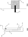
- a barrier separating the passage 106 from the flavourant reservoir 131b may be permeable to flavourant 130 as illustrated exemplarily in Figure 7.
- Figure 7 illustrates a perforated barrier 133 separating the passage 106 from the flavourant reservoir 131b.
- the barrier may thus comprise one or more small apertures 134 to permit the passage of flavourant therethrough, and may be formed as part of the sidewall of the flow passage 106.
- flavourant 130 may then permeate through the barrier 133 from the flavourant reservoir 131b to the passage 106, for example by capillary action, so as to be exposed to the airflow in the passage 106 (i.e. caused by a user inhaling).
- the flavourant reservoir 131b is housed within the flow passage 106 so as to extend substantially completely across the flow passage 106.
- the flavourant reservoir 131b is provided with a plurality of relatively small diameter bores 106c, each of which extends fully through the reservoir from its upstream end to its downstream end.
- Each bore 106c may be defined by a similar permeable barrier 133c (each of which may thus be perforated with small apertures 134c) in a similar manner to the barrier arrangement described above with reference to Figure 6 .
- fluid flow through the flow passage 106 will thus become split into separate flow streams through the bores 106c of the reservoir, the flow streams then rejoining and mixing with one another downstream of the reservoir.
- This type of multi-bore configuration of the reservoir 131c can be effective to increase the effective surface area through which the flavourant can permeate, when compared to the single barrier arrangement of Figure 6 , which can be effective to increase the concentration of flavourant which may be entrained in the airflow through the passage 106.
- the source of flavourant 130 may be a flavoured article 135, comprising a substrate 136 carrying the flavourant 130.
- a flavoured article 135 may be received within the fluid flow passage 106, which may be shaped to provide a recess, receptacle, or chamber 120 within which the flavoured article 135 may be located.
- At least part of the substrate 136 may be formed from a polymeric material (e.g. silicone). Further, at least part of the substrate 136 may be formed from a porous material, foam or foamed material as illustrated exemplarily in Figure 9 . Still further, at least a part of the substrate 136 may be formed from an air permeable material.
- the flavourant 130 may be one or both of comprised within or coated on a surface of the substrate 136.
- the flavourant 130 may be introduced into the flavoured article 135 by coating (e.g. spray coating).
- the flavourant 130 may be introduced or impregnated into the flavoured article 135 by, for example, immersion of the substrate 136 in a liquid comprising flavourant 130. This process of introducing flavourant 130 could either be carried out during manufacture of the flavoured article 135, or by an end-user.
- the source of flavourant 130 may be a "flavour pod" 137 comprising a container 138 at least partially filled with the flavourant 130.
- a flavour pod 137 may be received within the passage 106, which may be shaped to provide a recess or receptacle into which the flavour pod 137 may be located. When in place, a surface of the flavour pod 137 may define part of a peripheral wall of the passage 106.
- the flavour pod, denoted as 137a in Figure 10 may furthermore comprise one or more porous wicks 139 extending at least partially across the passage 106 (e.g. transverse to a longitudinal axis of the passage 106) so as to be presented to a fluid flow therethrough.
- each porous wick 139 extends into the flavour pod container 138, so as to be submerged in the flavourant 130. In this way, the flavourant 130 contained in the flavour pod container 138 is conveyed from the end or ends of the porous wick 139 extending into the flavour pod container 138 to a portion of the porous wick 139 located within the passage 106 so as to be exposed to the airflow therein (i.e. caused by a user inhaling).
- flavourant 130 may permeate from the flavour pod 137 to the passage 106 for entrainment in the airflow therethrough (i.e. caused by a user inhaling).
- the recess or receptacle 120 in which flavoured article 135 or flavour pod 137 is locatable may be provided within the main body 102, the system 101, or within the consumable 103.
- the flavoured article 135 or flavour pod 137 may be a removable, replaceable, and/or consumable flavour part 140 of the smoking substitute system 101.
- the flavoured article 135 or flavour pod 137 may be releasably attached to the consumable 103, for example to the end of the consumable which is configured to engage with the main body 102.
- Various means of attachment between the source of flavourant 130 and the consumable 103 may be possible, including, but not limited to, an interference fit, a snap fit comprising one or more raised bumps and corresponding recesses on the interfacial surface between the two components, or through physically coupling together by screwing one onto the other, through a bayonet fitting, through a latching mechanism, or through a clip or clasp. If the source of flavourant 130 is attached via a latching mechanism, this may further include a button by which the latch may be released.
- a clip or clasp may be fixed in position relative to the consumable 103, or hingedly, rotatably, or slidably attached to the consumable so as to be movable to allow the flavoured article 135 or flavour pod 137 to be fitted and released.
- the flavoured article 135 or flavour pod 137 may alternatively be comprised within a flavour part 140 of the smoking system, in the manner illustrated schematically in Figures 13 and 14 .
- Said flavour part 140 may be located between the consumable 103 and main body 102, such that each engages with an opposing end or side of the flavour part 140, but not directly with each other.
- the flavour part 140 in such an embodiment may further comprise an electrical contact 112b and connection therethrough, so that power may be conveyed from the contacts of the main body 102 to the contacts 112 of the consumable 103 via the flavour part 140.
- the interface between the consumable 103 and flavour part 140 may be configured to be the same as the interface between the flavour part 140 and main body 102, such that the user is afforded the option of choosing to use the smoking substitute device 101 either with or without the flavour part 140.
- a flavoured article 135 or flavour pod 137 may therefore be provided as a stand-alone consumable, independent of the consumable 103 comprising the aerosol generator.
- One or more flavoured articles 135 or flavour pods 137 may be provided in a retail pack.
- Each flavoured article 135 or flavour pod 137 within a pack may comprise the same flavourant 130.
- the pack may comprise flavoured articles 135 or flavour pods 137 containing different flavourants 130, in order to provide a user with a selection of possible flavourants 130.
- one or more consumables 103b may be provided in a retail pack.
- Each consumable 103b within a pack may comprise the same flavourant 130.
- the pack may comprise consumables 103b containing different flavourants 130 in order to provide a user with a selection of possible flavourants 130.
Priority Applications (3)
| Application Number | Priority Date | Filing Date | Title |
|---|---|---|---|
| EP19155862.6A EP3692832A1 (de) | 2019-02-07 | 2019-02-07 | Rauchersatzvorrichtung |
| PCT/EP2020/053110 WO2020161289A1 (en) | 2019-02-07 | 2020-02-07 | Smoking substitute device |
| US17/395,276 US20220022537A1 (en) | 2019-02-07 | 2021-08-05 | Smoking substitute apparatus |
Applications Claiming Priority (1)
| Application Number | Priority Date | Filing Date | Title |
|---|---|---|---|
| EP19155862.6A EP3692832A1 (de) | 2019-02-07 | 2019-02-07 | Rauchersatzvorrichtung |
Publications (1)
| Publication Number | Publication Date |
|---|---|
| EP3692832A1 true EP3692832A1 (de) | 2020-08-12 |
Family
ID=65363084
Family Applications (1)
| Application Number | Title | Priority Date | Filing Date |
|---|---|---|---|
| EP19155862.6A Ceased EP3692832A1 (de) | 2019-02-07 | 2019-02-07 | Rauchersatzvorrichtung |
Country Status (2)
| Country | Link |
|---|---|
| EP (1) | EP3692832A1 (de) |
| WO (1) | WO2020161289A1 (de) |
Cited By (1)
| Publication number | Priority date | Publication date | Assignee | Title |
|---|---|---|---|---|
| WO2022057307A1 (zh) * | 2020-09-21 | 2022-03-24 | 深圳雾芯科技有限公司 | 电子烟主体、雾化设备以及电子烟 |
Families Citing this family (1)
| Publication number | Priority date | Publication date | Assignee | Title |
|---|---|---|---|---|
| JPWO2023286239A1 (de) * | 2021-07-15 | 2023-01-19 |
Citations (5)
| Publication number | Priority date | Publication date | Assignee | Title |
|---|---|---|---|---|
| WO2014110119A1 (en) * | 2013-01-08 | 2014-07-17 | L. Perrigo Company | Electronic cigarette |
| DE202014001718U1 (de) * | 2014-02-27 | 2015-05-28 | Xeo Holding GmbH | Rauchvorrichtung |
| GB2529201A (en) * | 2014-08-13 | 2016-02-17 | Batmark Ltd | Device and method |
| WO2017141017A1 (en) * | 2016-02-18 | 2017-08-24 | British American Tobacco (Investments) Limited | Flavour delivery device |
| WO2017185051A1 (en) * | 2016-04-22 | 2017-10-26 | Pax Labs, Inc. | Aerosol devices having compartmentalized materials |
-
2019
- 2019-02-07 EP EP19155862.6A patent/EP3692832A1/de not_active Ceased
-
2020
- 2020-02-07 WO PCT/EP2020/053110 patent/WO2020161289A1/en active Application Filing
Patent Citations (5)
| Publication number | Priority date | Publication date | Assignee | Title |
|---|---|---|---|---|
| WO2014110119A1 (en) * | 2013-01-08 | 2014-07-17 | L. Perrigo Company | Electronic cigarette |
| DE202014001718U1 (de) * | 2014-02-27 | 2015-05-28 | Xeo Holding GmbH | Rauchvorrichtung |
| GB2529201A (en) * | 2014-08-13 | 2016-02-17 | Batmark Ltd | Device and method |
| WO2017141017A1 (en) * | 2016-02-18 | 2017-08-24 | British American Tobacco (Investments) Limited | Flavour delivery device |
| WO2017185051A1 (en) * | 2016-04-22 | 2017-10-26 | Pax Labs, Inc. | Aerosol devices having compartmentalized materials |
Cited By (1)
| Publication number | Priority date | Publication date | Assignee | Title |
|---|---|---|---|---|
| WO2022057307A1 (zh) * | 2020-09-21 | 2022-03-24 | 深圳雾芯科技有限公司 | 电子烟主体、雾化设备以及电子烟 |
Also Published As
| Publication number | Publication date |
|---|---|
| WO2020161289A1 (en) | 2020-08-13 |
Similar Documents
| Publication | Publication Date | Title |
|---|---|---|
| CN110996694A (zh) | 气溶胶生成装置及生成方法 | |
| EP3920738B1 (de) | Rauchersatzvorrichtung | |
| EP3692830A1 (de) | Rauchersatzvorrichtung | |
| WO2020161289A1 (en) | Smoking substitute device | |
| EP3693293A1 (de) | Verpackung für rauchersatzvorrichtung | |
| WO2019211339A1 (en) | Smoking substitute device having a liquid impermeable filter between the mouthpiece and the liquid tank | |
| WO2020161302A1 (en) | Flavour delivery article, smoking substitute apparatus and smoke substitute device | |
| WO2020161330A1 (en) | Smoking substitute apparatus | |
| WO2020161296A1 (en) | Smoking substitute apparatus | |
| EP3920739B1 (de) | Rauchersatzvorrichtung | |
| EP3692831A1 (de) | Rauchersatzvorrichtung | |
| WO2020161307A1 (en) | Smoking substitute apparatus | |
| EP3920744B1 (de) | Rauchersatzvorrichtung | |
| EP3692833A1 (de) | Rauchersatzvorrichtung | |
| EP3692841A1 (de) | Rauchersatzvorrichtung | |
| US20220378093A1 (en) | Smoking substitute component | |
| EP3692823A1 (de) | Rauchersatzvorrichtung, kappe für eine rauchvorrichtung und zugehörige herstellungsverfahren | |
| US20220202073A1 (en) | Smoking substitute apparatus | |
| EP3693291A1 (de) | Verpackung für rauchersatzvorrichtung | |
| EP3692822A1 (de) | Aromafreisetzungsartikel für eine rauchersatzvorrichtung | |
| EP3692840A1 (de) | Rauchersatzvorrichtung und rauchersatzkit | |
| EP3692816A1 (de) | Aromafreisetzungsartikel | |
| WO2023041438A1 (en) | Flavourant provider and smoking substitute device | |
| EP3692821A1 (de) | Rauchersatzvorrichtung | |
| WO2023052085A1 (en) | Vaporisable liquid for a smoking substitute apparatus |
Legal Events
| Date | Code | Title | Description |
|---|---|---|---|
| PUAI | Public reference made under article 153(3) epc to a published international application that has entered the european phase |
Free format text: ORIGINAL CODE: 0009012 |
|
| STAA | Information on the status of an ep patent application or granted ep patent |
Free format text: STATUS: THE APPLICATION HAS BEEN PUBLISHED |
|
| AK | Designated contracting states |
Kind code of ref document: A1 Designated state(s): AL AT BE BG CH CY CZ DE DK EE ES FI FR GB GR HR HU IE IS IT LI LT LU LV MC MK MT NL NO PL PT RO RS SE SI SK SM TR |
|
| AX | Request for extension of the european patent |
Extension state: BA ME |
|
| 18R | Application refused |
Effective date: 20201116 |