EP3692799A1 - Ice cream maker fitting for a stand mixer, ice cream maker kit for a stand mixer and stand mixer - Google Patents
Ice cream maker fitting for a stand mixer, ice cream maker kit for a stand mixer and stand mixer Download PDFInfo
- Publication number
- EP3692799A1 EP3692799A1 EP20155961.4A EP20155961A EP3692799A1 EP 3692799 A1 EP3692799 A1 EP 3692799A1 EP 20155961 A EP20155961 A EP 20155961A EP 3692799 A1 EP3692799 A1 EP 3692799A1
- Authority
- EP
- European Patent Office
- Prior art keywords
- stand mixer
- bowl
- ice cream
- fitting
- double wall
- Prior art date
- Legal status (The legal status is an assumption and is not a legal conclusion. Google has not performed a legal analysis and makes no representation as to the accuracy of the status listed.)
- Granted
Links
Images

Classifications
-
- A—HUMAN NECESSITIES
- A23—FOODS OR FOODSTUFFS; TREATMENT THEREOF, NOT COVERED BY OTHER CLASSES
- A23G—COCOA; COCOA PRODUCTS, e.g. CHOCOLATE; SUBSTITUTES FOR COCOA OR COCOA PRODUCTS; CONFECTIONERY; CHEWING GUM; ICE-CREAM; PREPARATION THEREOF
- A23G9/00—Frozen sweets, e.g. ice confectionery, ice-cream; Mixtures therefor
- A23G9/04—Production of frozen sweets, e.g. ice-cream
- A23G9/08—Batch production
- A23G9/12—Batch production using means for stirring the contents in a non-moving container
-
- A—HUMAN NECESSITIES
- A23—FOODS OR FOODSTUFFS; TREATMENT THEREOF, NOT COVERED BY OTHER CLASSES
- A23G—COCOA; COCOA PRODUCTS, e.g. CHOCOLATE; SUBSTITUTES FOR COCOA OR COCOA PRODUCTS; CONFECTIONERY; CHEWING GUM; ICE-CREAM; PREPARATION THEREOF
- A23G9/00—Frozen sweets, e.g. ice confectionery, ice-cream; Mixtures therefor
- A23G9/04—Production of frozen sweets, e.g. ice-cream
- A23G9/22—Details, component parts or accessories of apparatus insofar as not peculiar to a single one of the preceding groups
- A23G9/222—Freezing drums
-
- A—HUMAN NECESSITIES
- A23—FOODS OR FOODSTUFFS; TREATMENT THEREOF, NOT COVERED BY OTHER CLASSES
- A23G—COCOA; COCOA PRODUCTS, e.g. CHOCOLATE; SUBSTITUTES FOR COCOA OR COCOA PRODUCTS; CONFECTIONERY; CHEWING GUM; ICE-CREAM; PREPARATION THEREOF
- A23G9/00—Frozen sweets, e.g. ice confectionery, ice-cream; Mixtures therefor
- A23G9/04—Production of frozen sweets, e.g. ice-cream
- A23G9/22—Details, component parts or accessories of apparatus insofar as not peculiar to a single one of the preceding groups
- A23G9/224—Agitators or scrapers
Definitions
- the invention relates to an ice cream maker fitting for a stand mixer, to an ice cream maker kit for a stand mixer and to a stand mixer.
- the invention relates to a fitting and to a kit for a stand mixer with a "planetary" movement.
- Stand mixers of this type are provided with different fittings, which expand the functions of the stand mixer itself beyond the simple mixing action.
- an object of the invention to provide an ice cream maker fitting for a stand mixer, which is functional and efficient and, at the same time, is simple to be manufactured and easy to be used.
- the invention relates to an ice cream maker fitting for a stand mixer provided with a bowl; the fitting comprising:
- a further object of the invention is to provide an ice cream maker kit, which is easy to be mounted and, at the same time, ensures satisfying results from the functional point of view.
- the invention relates to an ice cream maker kit according to claim 10.
- a further object of the invention is to provide a stand mixer, which is capable of creating ice cream in a simple and effective manner, ensuring a high-quality result.
- the invention relates to a stand mixer according to claim 11.
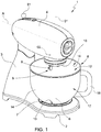
- reference number 1 indicates a stand mixer.
- the stand mixer 1 is commonly designed to stand on a table.
- the stand mixer 1 basically is a home appliance provided with a base 2, an upright 3 vertically projecting from the base 2, a main body 4 hinged to the vertical upright 3, at least one motor (not visible in the accompanying figures) and at least one bowl 6.
- the base 2 is provided with a seat 7, which is designed to be selectively engaged by the bowl 6.
- the base 2 and the bowl 6 are preferably configured so as to form a firm coupling, for example a bayonet coupling.
- the bowl 6 can be fixed to the upright 3, for example by means of one or more arms.
- the main body 4 extends around an axis A and is hinged to the upright 3 so as to be movable between an operating position and a non-operating position.
- the axis A of the main body 4 is substantially orthogonal to the vertical axis. In other words, the axis A of the main body is horizontal.
- the main body 4 In the non-operating position, the main body 4 is raised relative to the operating position. In the non-operating position, the axis A of the main body is transverse to the vertical axis, but not orthogonal thereto.
- the motor (which is not shown in the accompanying figures for the sake of simplicity) is preferably housed in the main body 4.
- the main body 4 also houses, on the inside, a gear (also not visible in the figures), which is configured to transform the rotary motion of the shaft of the motor (not visible) into a planetary motion of an attack pin 8, which is provided with a free portion 9 projecting out of the main body 4.
- a gear also not visible in the figures
- the free portion 9 of the attack pin 8 is configured to be coupled, in use, to a respective tool (not shown in the accompanying figures).
- the tool generally is a kneading tool, such as for example a whisker or a dough hook, etc.
- the free portion 9 of the attack pin 8 always faces the inside of the bowl 6 during the entire planetary movement. In this way, the tool, in use, is housed inside the bowl 6.
- the gear is configured to rotate a cap 10 of the main body 4 around a first rotation axis 01 and to rotate the attack pin 8 around a further rotation axis O2.
- the attack pin 8 is fixed to the rotating cap 10.
- the first rotation axis 01 and the second rotation axis O2 are parallel.
- the direction of rotation of the cap 10 around the first rotation axis preferably is contrary to the direction of rotation of the attack pin 8 around the second axis O2. In this way, in use, the action of the tool inside the bowl 6 is optimized.
- the attack pin 8 carries out a planetary movement, since it makes a rotation movement around its own axis (O2) and, at the same time, a rotation movement around another parallel axis (01).
- the bowl 6 extends around an axis B and defines a processing chamber 12.
- the bowl 6 has a bottom wall 13 and a side wall 14.
- the bottom wall 13 and the side wall 14 are preferably manufactured as one single piece.
- the bottom wall 13 defines an inner bottom face (not visible in the accompanying figures), which faces the processing chamber 12, and an outer bottom wall (not visible in the accompanying figures), which is preferably coupled to the base 2.
- the inner bottom wall preferably has substantially a semi-spherical shape.
- the side wall 14 defines an inner side face 16, which faces the processing chamber 12, and an outer side face 17, which is provided with a handle 18.
- the bowl 6, when it is coupled to the base, is preferably centred relative to the rotation axis 01. In other words, when the bowl is coupled to the base, the axis B coincides with the axis 01.
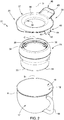
- Figure 2 shows a first ice cream maker fitting 20 of an ice cream maker kit 21 according to the invention.
- the ice cream maker kit 21 further comprises a second fitting 22 (shown in figures 5 , 6 and 7 ) and a blade for processing the ingredients 23 (visible in figures 5 , 6 ).
- the first fitting 20 comprises a double wall vessel 25 and a fixing system 26 configured to fix the double wall vessel 25 to the bowl 6 of the stand mixer 1.
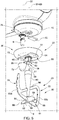
- the double wall vessel 25 extends around an axis C and comprises an outer wall 28 and an inner wall 29, which are coupled so as to define, between the outer wall 28 and the inner wall 29, a sealed space 30, wherein a refrigerant fluid 31, preferably a refrigerant liquid, is arranged.
- the refrigerant liquid 31 preferably is a mixture of water and sodium chloride.
- concentration of said sodium chloride preferably ranges from 20% to 30% and preferably is equal to 23%.
- the inner wall 29 is preferably configured to define a chamber 32 with a substantially cylindrical shape.
- the inner wall 29 preferably is at least partially made of a metal material (for example stainless steel) so as to enhance the transmission of heat as well as the cooling of the ingredients arranged in the chamber 32 of the double wall vessel 25.
- a metal material for example stainless steel
- the double wall vessel 25 is at least partly housed, in use, inside the processing chamber 12 of the bowl 6 and is provided with a plurality of support pins 33, which are configured so as to rest against the inner bottom wall of the bowl 6.
- the support pins 33 are preferably made of a non-slip material.
- the double wall vessel 25 has to be left in a freezer for an amount of time of at least 12 hours, so that the refrigerant liquid freezes.
- the refrigerant liquid can preserve a desired temperature (for example approximately -10°C) for an amount of time of at least 2 hours. This allows for a reduction of the temperature of the ingredients, so that they thicken during the mixing.
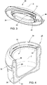
- the fixing system 26 comprises an annular element 35 extending around an axis D and provided with an inner edge 36 and with an outer edge 37.
- the inner edge 36 is coupled to the double wall vessel 25 and the outer edge 37 is coupled to the bowl 6 of the stand mixer 1.
- the inner edge 36 is preferably coupled to the double wall vessel 25 by means of a bayonet coupling system.
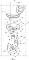
- the double wall vessel 25 is provided with two male bayonet components 38, which project from the double wall vessel 25, substantially close to a peripheral edge 39 of the container 25, so as to engage two respective female bayonet components 40 (only one of them being visible in figure 3 ) of the inner edge 36 of the annular element 35.
- the male bayonet components 38 preferably are two teeth, which project from the inner wall 29, close to the peripheral edge 39 of the double wall vessel 25.
- the female bayonet components 40 are two grooves (only one of them being visible in figure 3 ) made in an annular wall 41 axially projecting from the inner edge 36 of the annular element 35.
- the outer edge 37 of the annular element 35 is coupled to the bowl 6 by means of an anti-rotation device 43.
- the anti-rotation device 43 is configured to prevent the double wall vessel 25 and the bowl 6 from rotating relative to one another.
- the anti-rotation device 43 comprises a fixing element 44, which can be coupled to the handle 18 of the bowl 6.
- the fixing element 44 comprises a tongue 45, which axially projects from the outer edge 37 of the annular element 35 towards the bowl 6, so as to cooperate with at least a portion of the handle 18.
- the tongue 45 is preferably provided with an open seat 46, which is configured to house, in use, a portion of the handle 18 of the bowl 6 of the stand mixer 1, so as to lock rotary movements of the annular element 35 relative to the bowl 6.
- Figure 7 shows the handle 18 engaging the seat 46.
- the seat 46 is a recess of the tongue 45 having an axial length that is such as to house a portion of the handle 18 that is sufficient to avoid the relative rotary movement between the annular element 35 and the bowl 6.
- the tongue 45 basically acts like a fork which, coupled to the handle 18 of the bowl 6, prevents the double wall vessel 25 from freely rotating during the operation of the stand mixer 1.
- the outer edge of the annular element 35 is provided with one or more locking elements configured to fix the annular element 35 to the edge of the bowl 6.
- the annular element 35 makes sure that the double wall vessel 25 is centred relative to the bowl 6.
- the axis C of the double wall vessel 25 coincides with the axis B of the bowl 6.
- the annular element 35 is preferably provided with a slide 48 provided with a sliding plane 49.
- the slide 48 is coupled to the annular element 35 so that the sliding plane 49 of the slide 48 is connected to the inner edge 36 of the annular element 35 without gaps.
- the slide 48 in use, helps ice cream ingredients be introduced into the double wall vessel 25 even when the motor is active.
- Figures 5 and 6 show the second ice cream maker fitting 22 and the ingredient processing blade 23 of the ice cream maker kit 21 according to the invention.
- the second ice cream maker fitting 22 comprises an adapter element 50, which is configured to cause a rotation of the ingredient processing blade 23 coupled to it around a rotation axis O3.
- the rotation axis O3 preferably coincides with the rotation axis 01.
- the adapter element 50 is configured to obtain a rotary motion of the ingredient processing blade 23 around one single axis, preferably the same rotation axis 01 as the cap 10.
- the adapter element 50 is coupled to the movable cap 10 of the main body 4.
- the coupling between the adapter element 50 and the movable cap 10 preferably is a magnetic coupling.
- the adapter element 50 preferably comprises a magnet 53 and the cap 10 (or the main body 4) comprises at least one metallic element (not visible in the accompanying figures) capable of attracting the magnet 53.
- the movable cap 10 preferably comprises an element made of cast iron (not visible in the accompanying figures).
- the adapter element 50 comprises a plate 54 provided with an inner face 55 (better visible in figure 6 ), which is designed to be coupled to the cap 10 of the main body 4, and with an outer face 56 (better visible in figure 5 ), which is designed to face, in use, the double wall container 25.
- the adapter element 50 is provided with a coupling element 58, which is configured to be coupled to the ingredient processing blade 23.
- the coupling element 58 preferably is a pin projecting from the outer face 56, substantially orthogonally to the outer face 56.
- the pin 58 is preferably arranged so as to be coaxial to the rotation axis 01 of the cap 10 of the main body 4.
- the pin 58 preferably is hollow.
- the pin 58 is preferably shaped so as to be easily coupled to the ingredient processing blade 23.
- the shape of the pin 58 facilitates the self-centring of the pin 58 itself in a respective seat 59 made in a shaft 60 of the ingredient processing blade 23.
- the ingredient processing blade 23 is provided with a pin engaging a respective seat obtained in the adapter element 50.
- the pin 58 is preferably manufactured as one single piece together with the plate 54.
- the pin 58 has a cylindrical end portion 61 and a toothed portion 62, which is provided with teeth 63 with oblique sides and is contiguous to the cylindrical end portion 61.
- the toothed portion 62 has a substantially truncated cone shaped part 65 and a substantially cylindrical part 66.
- the truncated cone shaped part 65 is placed in contact with the end portion 61 and has a diameter that increases starting from the end portion 61 up to the cylindrical part 66.
- the seat 59 in the shaft 60 of the ingredient processing blade 23 is defined by a wall 68 provided with an inner face 69 provided with grooves 70 with oblique sides, which are complementary to the teeth 63 of the toothed portion 62 of the pin 58.
- the plate 54 further has a through hole 71, which is placed so as to be engaged by the attack pin 9 when the adapter element 50 is coupled to the cap 10 of the main body 4.
- the adapter element 50 is preferably provided with a covering element 72 in the area of the through hole 71, which is configured to cover the attack pin 9.
- the covering element 72 is preferably defined by a hollow body, which extends around the through hole 71 and protrudes from the outer face 56 of the plate 54. In this way the attack pin 9 is protected from possible squirts during the operation of the stand mixer 1 provided with the ice cream maker kit 21.
- the covering element 72 preferably has an end portion with the shape of a truncated cone.
- the covering element 72 is preferably manufactured as one single piece together with the plate 54.
- the covering element 72 faces the pin 58.
- the covering element 72 and the pin 58 project from a bulge 73 of the outer face 56, which corresponds to a recess 74 of the inner face 55.
- the recess 74 houses, in use, a respective protrusion 74 of the cap 10.
- the magnet 53 is preferably housed in a respective cavity 76 of the inner face 55 corresponding to a protrusion 77 of the outer face 56 of the plate 54.
- the ingredient processing blade 23 is provided with a shaft 60 extending along a longitudinal axis E and with at least one processing element 80.
- the blade 23 is arranged in the double wall vessel 25 and is coupled to the pin 58.
- the processing element 80 is preferably configured to carry out a combined mixing-lifting-air incorporating action during the rotation of the blade 23.
- the mixing element 80 comprises a substantially U-shaped plate 81, which is provided with a base 82 and with two arms 83a, 83b, which substantially extend parallel to the shaft 60.
- An arm 83a has a corrugated outer edge 84.
- the other arm 83b has an outer edge 85, which is shaped so as to substantially scrape a portion of the inner wall 29 of the double wall vessel 25.
- the arms 83a, 83b preferably extend parallel to the axis E and the base 82 is orthogonal to the axis E.
- the mixing element 80 is preferably also provided with a joining element 86, which connects the free end of the arm 83b to the base of the arm 83a.
- the joining element 86 preferably intercepts the shaft 60.
- the joining element 86 connects the free end of the arm 83a to the base of the arm 83b.
- the mixing element 80 is preferably also provided with two wings 88, which extend from opposite faces of the base 82 of the plate 81 orthogonally to the base 82.
- the wings are preferably inclined relative to the axis E of the blade 23 and are symmetrical relative to the axis E.
- the wings 88 have a flat edge 89, which is designed to be placed in contact with the bottom of the double wall vessel 25 and, a rounded edge 90.
- the wings 88 in use, allow the blade 23 to firmly rest against the bottom of the double wall vessel 25 and stiffen the blade 23.
- the wings 88 help make the mixing action effective, in particular in the initial phases, when an iced crust can form in contact with the inner wall of the double wall vessel 25.
- Figure 7 shows a stand mixer 1 where an ice cream maker kit 21 according to the invention is mounted.
- the installation entails coupling the ice cream maker fitting 20 to the bowl 6 of the stand mixer 1 and fixing the bowl 6 to the base 2 of the stand mixer.
- the ice cream maker fitting 20 must be coupled to the bowl 6 after the double wall vessel 25 has been sufficiently cooled (for example has been left in a freezer for at least 12 hours).
- the ice cream maker fitting 22 has to be coupled to the cap 10 of the main body 4 when the main body 4 is in the non-operating position. This last phase can be carried out both before the coupling of the fitting 20 to the bowl 6 and after.
- the blade 23 is placed so as to rest against the bottom of the double wall vessel 25 of the stand mixer 1 and the main body 4 is then moved to the operating position.
- the pin 58 engages the seat 59 of the shaft 60 of the blade 23, thus self-centring the blade 23 relative to the pin 58.
- the controlled activation of the motor determines the rotation of the blade 23.
- the ice cream maker kit 21 according to the invention is simple to be installed and ensures the production of high-quality ice cream.
- the ice cream maker fitting 20 allows the bowl 6 that comes with the stand mixer 1 to be exploited for the production of ice cream, without requiring dedicated systems for the coupling to the base 2 and without jeopardizing the final appearance of the stand mixer 1.
- the ice cream maker fitting 22 allows the blade 23 to be operated in a stable and safe manner.
- the coupling to the main body 4 is simple and effective and, again, the final appearance of the stand mixer 1 is not jeopardized.
Landscapes
- Engineering & Computer Science (AREA)
- Life Sciences & Earth Sciences (AREA)
- Chemical & Material Sciences (AREA)
- Food Science & Technology (AREA)
- Polymers & Plastics (AREA)
- Manufacturing & Machinery (AREA)
- Confectionery (AREA)
- Food-Manufacturing Devices (AREA)
Abstract
Description
- This Patent Application claims priority from Italian Patent Application No.
102019000001727 filed on February 6, 2019 - The invention relates to an ice cream maker fitting for a stand mixer, to an ice cream maker kit for a stand mixer and to a stand mixer.
- In particular, the invention relates to a fitting and to a kit for a stand mixer with a "planetary" movement.
- Stand mixers of this type, indeed, are provided with different fittings, which expand the functions of the stand mixer itself beyond the simple mixing action.
- The attention of manufacturers is focused on providing fittings that are easy to be used and, at the same time, ensure satisfying results from the functional point of view.
- Therefore, it is an object of the invention to provide an ice cream maker fitting for a stand mixer, which is functional and efficient and, at the same time, is simple to be manufactured and easy to be used.
- According to this object, the invention relates to an ice cream maker fitting for a stand mixer provided with a bowl; the fitting comprising:
- a double wall vessel comprising an outer wall and an inner wall, which are coupled so as to define between the outer wall and the inner wall a sealed space, wherein a refrigerant fluid is arranged; the double wall vessel being sized so as to be arranged, in use, inside the bowl of the stand mixer;
- a fixing system configured to fix the double wall vessel to the bowl of the stand mixer.
- A further object of the invention is to provide an ice cream maker kit, which is easy to be mounted and, at the same time, ensures satisfying results from the functional point of view.
- In accordance with this object, the invention relates to an ice cream maker kit according to
claim 10. - Finally, a further object of the invention is to provide a stand mixer, which is capable of creating ice cream in a simple and effective manner, ensuring a high-quality result.
- In accordance with this object, the invention relates to a stand mixer according to claim 11.
- Further features and advantages of the invention will be best understood upon perusal of the following description of a non-limiting embodiment thereof, with reference to the accompanying drawing, wherein:
-
figure 1 is a perspective view, with parts removed for greater clarity, of a stand mixer; -
figure 2 is an exploded perspective view, with parts removed for greater clarity, of a first detail of an ice cream maker kit according to the invention and of a portion of the stand mixer; -
figure 3 is a perspective view of a second detail of the ice cream maker kit offigure 2 ; -
figure 4 is a sectional perspective view of a third detail of the ice cream maker kit offigure 2 ; -
figure 5 is an exploded perspective view, with parts removed for greater clarity, of a fourth detail of an ice cream maker kit according to the invention and of a portion of the stand mixer; -
figure 6 is a further exploded perspective view, with parts removed for greater clarity, of the fourth detail offigure 5 from a different angle; -
figure 7 is a perspective view, with parts removed for greater clarity, of the stand mixer and of the ice cream maker kit according to the invention. - In
figure 1 ,reference number 1 indicates a stand mixer. Thestand mixer 1 is commonly designed to stand on a table. - The
stand mixer 1 basically is a home appliance provided with abase 2, an upright 3 vertically projecting from thebase 2, amain body 4 hinged to the vertical upright 3, at least one motor (not visible in the accompanying figures) and at least onebowl 6. - The
base 2 is provided with aseat 7, which is designed to be selectively engaged by thebowl 6. - The
base 2 and thebowl 6 are preferably configured so as to form a firm coupling, for example a bayonet coupling. - According to a variant which is not shown herein, the
bowl 6 can be fixed to the upright 3, for example by means of one or more arms. - The
main body 4 extends around an axis A and is hinged to the upright 3 so as to be movable between an operating position and a non-operating position. - In the operating position, the axis A of the
main body 4 is substantially orthogonal to the vertical axis. In other words, the axis A of the main body is horizontal. - In the non-operating position, the
main body 4 is raised relative to the operating position. In the non-operating position, the axis A of the main body is transverse to the vertical axis, but not orthogonal thereto. - The motor (which is not shown in the accompanying figures for the sake of simplicity) is preferably housed in the
main body 4. - The
main body 4 also houses, on the inside, a gear (also not visible in the figures), which is configured to transform the rotary motion of the shaft of the motor (not visible) into a planetary motion of anattack pin 8, which is provided with afree portion 9 projecting out of themain body 4. - The
free portion 9 of theattack pin 8 is configured to be coupled, in use, to a respective tool (not shown in the accompanying figures). - The tool generally is a kneading tool, such as for example a whisker or a dough hook, etc.
- In the operating position, the
free portion 9 of theattack pin 8 always faces the inside of thebowl 6 during the entire planetary movement. In this way, the tool, in use, is housed inside thebowl 6. - In detail, the gear is configured to rotate a
cap 10 of themain body 4 around afirst rotation axis 01 and to rotate theattack pin 8 around a further rotation axis O2. Theattack pin 8 is fixed to the rotatingcap 10. Thefirst rotation axis 01 and the second rotation axis O2 are parallel. - The direction of rotation of the
cap 10 around the first rotation axis preferably is contrary to the direction of rotation of theattack pin 8 around the second axis O2. In this way, in use, the action of the tool inside thebowl 6 is optimized. - Basically, thanks to the gear, the
attack pin 8 carries out a planetary movement, since it makes a rotation movement around its own axis (O2) and, at the same time, a rotation movement around another parallel axis (01). - The
bowl 6 extends around an axis B and defines aprocessing chamber 12. In detail, thebowl 6 has abottom wall 13 and aside wall 14. Thebottom wall 13 and theside wall 14 are preferably manufactured as one single piece. - The
bottom wall 13 defines an inner bottom face (not visible in the accompanying figures), which faces theprocessing chamber 12, and an outer bottom wall (not visible in the accompanying figures), which is preferably coupled to thebase 2. - The inner bottom wall preferably has substantially a semi-spherical shape.
- The
side wall 14 defines aninner side face 16, which faces theprocessing chamber 12, and anouter side face 17, which is provided with ahandle 18. - The
bowl 6, when it is coupled to the base, is preferably centred relative to therotation axis 01. In other words, when the bowl is coupled to the base, the axis B coincides with theaxis 01. -
Figure 2 shows a first ice cream maker fitting 20 of an icecream maker kit 21 according to the invention. - The ice
cream maker kit 21 further comprises a second fitting 22 (shown infigures 5 ,6 and7 ) and a blade for processing the ingredients 23 (visible infigures 5 ,6 ). - The
first fitting 20 comprises adouble wall vessel 25 and afixing system 26 configured to fix thedouble wall vessel 25 to thebowl 6 of thestand mixer 1. - With reference to
figure 4 , thedouble wall vessel 25 extends around an axis C and comprises anouter wall 28 and aninner wall 29, which are coupled so as to define, between theouter wall 28 and theinner wall 29, a sealedspace 30, wherein arefrigerant fluid 31, preferably a refrigerant liquid, is arranged. - The
refrigerant liquid 31 preferably is a mixture of water and sodium chloride. The concentration of said sodium chloride preferably ranges from 20% to 30% and preferably is equal to 23%. - The
inner wall 29 is preferably configured to define achamber 32 with a substantially cylindrical shape. - The
inner wall 29 preferably is at least partially made of a metal material (for example stainless steel) so as to enhance the transmission of heat as well as the cooling of the ingredients arranged in thechamber 32 of thedouble wall vessel 25. - With reference to
figure 2 , thedouble wall vessel 25 is at least partly housed, in use, inside theprocessing chamber 12 of thebowl 6 and is provided with a plurality of support pins 33, which are configured so as to rest against the inner bottom wall of thebowl 6. The support pins 33 are preferably made of a non-slip material. - In use, the
double wall vessel 25 has to be left in a freezer for an amount of time of at least 12 hours, so that the refrigerant liquid freezes. After having been frozen, the refrigerant liquid can preserve a desired temperature (for example approximately -10°C) for an amount of time of at least 2 hours. This allows for a reduction of the temperature of the ingredients, so that they thicken during the mixing. - The fixing
system 26 comprises anannular element 35 extending around an axis D and provided with aninner edge 36 and with anouter edge 37. Theinner edge 36 is coupled to thedouble wall vessel 25 and theouter edge 37 is coupled to thebowl 6 of thestand mixer 1. - The
inner edge 36 is preferably coupled to thedouble wall vessel 25 by means of a bayonet coupling system. - In the non-limiting example described and shown herein, the
double wall vessel 25 is provided with twomale bayonet components 38, which project from thedouble wall vessel 25, substantially close to aperipheral edge 39 of thecontainer 25, so as to engage two respective female bayonet components 40 (only one of them being visible infigure 3 ) of theinner edge 36 of theannular element 35. Themale bayonet components 38 preferably are two teeth, which project from theinner wall 29, close to theperipheral edge 39 of thedouble wall vessel 25. - With reference to
figure 3 , thefemale bayonet components 40 are two grooves (only one of them being visible infigure 3 ) made in anannular wall 41 axially projecting from theinner edge 36 of theannular element 35. - The
outer edge 37 of theannular element 35 is coupled to thebowl 6 by means of ananti-rotation device 43. Theanti-rotation device 43 is configured to prevent thedouble wall vessel 25 and thebowl 6 from rotating relative to one another. - In the non-limiting example shown herein, the
anti-rotation device 43 comprises a fixingelement 44, which can be coupled to thehandle 18 of thebowl 6. - In particular, the fixing
element 44 comprises atongue 45, which axially projects from theouter edge 37 of theannular element 35 towards thebowl 6, so as to cooperate with at least a portion of thehandle 18. Thetongue 45 is preferably provided with anopen seat 46, which is configured to house, in use, a portion of thehandle 18 of thebowl 6 of thestand mixer 1, so as to lock rotary movements of theannular element 35 relative to thebowl 6.Figure 7 shows thehandle 18 engaging theseat 46. - In other words, the
seat 46 is a recess of thetongue 45 having an axial length that is such as to house a portion of thehandle 18 that is sufficient to avoid the relative rotary movement between theannular element 35 and thebowl 6. - The
tongue 45 basically acts like a fork which, coupled to thehandle 18 of thebowl 6, prevents thedouble wall vessel 25 from freely rotating during the operation of thestand mixer 1. - According to a variant which is not shown herein, the outer edge of the
annular element 35 is provided with one or more locking elements configured to fix theannular element 35 to the edge of thebowl 6. - Advantageously, the
annular element 35 makes sure that thedouble wall vessel 25 is centred relative to thebowl 6. In other words, the axis C of thedouble wall vessel 25 coincides with the axis B of thebowl 6. - The
annular element 35 is preferably provided with aslide 48 provided with a slidingplane 49. - The
slide 48 is coupled to theannular element 35 so that the slidingplane 49 of theslide 48 is connected to theinner edge 36 of theannular element 35 without gaps. - The
slide 48, in use, helps ice cream ingredients be introduced into thedouble wall vessel 25 even when the motor is active. -
Figures 5 and6 show the second ice cream maker fitting 22 and theingredient processing blade 23 of the icecream maker kit 21 according to the invention. - The second ice cream maker fitting 22 comprises an
adapter element 50, which is configured to cause a rotation of theingredient processing blade 23 coupled to it around a rotation axis O3. The rotation axis O3 preferably coincides with therotation axis 01. - In other words, the
adapter element 50 is configured to obtain a rotary motion of theingredient processing blade 23 around one single axis, preferably thesame rotation axis 01 as thecap 10. - The
adapter element 50 is coupled to themovable cap 10 of themain body 4. - The coupling between the
adapter element 50 and themovable cap 10 preferably is a magnetic coupling. - The
adapter element 50 preferably comprises amagnet 53 and the cap 10 (or the main body 4) comprises at least one metallic element (not visible in the accompanying figures) capable of attracting themagnet 53. Themovable cap 10 preferably comprises an element made of cast iron (not visible in the accompanying figures). - The
adapter element 50 comprises aplate 54 provided with an inner face 55 (better visible infigure 6 ), which is designed to be coupled to thecap 10 of themain body 4, and with an outer face 56 (better visible infigure 5 ), which is designed to face, in use, thedouble wall container 25. - Along the
outer face 56, theadapter element 50 is provided with acoupling element 58, which is configured to be coupled to theingredient processing blade 23. - The
coupling element 58 preferably is a pin projecting from theouter face 56, substantially orthogonally to theouter face 56. - The
pin 58 is preferably arranged so as to be coaxial to therotation axis 01 of thecap 10 of themain body 4. - The
pin 58 preferably is hollow. - The
pin 58 is preferably shaped so as to be easily coupled to theingredient processing blade 23. In particular, the shape of thepin 58 facilitates the self-centring of thepin 58 itself in arespective seat 59 made in ashaft 60 of theingredient processing blade 23. - According to a variant which is not shown herein, the
ingredient processing blade 23 is provided with a pin engaging a respective seat obtained in theadapter element 50. - The
pin 58 is preferably manufactured as one single piece together with theplate 54. - With reference to
figure 5 , thepin 58 has acylindrical end portion 61 and atoothed portion 62, which is provided withteeth 63 with oblique sides and is contiguous to thecylindrical end portion 61. - The
toothed portion 62 has a substantially truncated cone shapedpart 65 and a substantiallycylindrical part 66. The truncated cone shapedpart 65 is placed in contact with theend portion 61 and has a diameter that increases starting from theend portion 61 up to thecylindrical part 66. - With reference to
figure 6 , theseat 59 in theshaft 60 of theingredient processing blade 23 is defined by awall 68 provided with aninner face 69 provided withgrooves 70 with oblique sides, which are complementary to theteeth 63 of thetoothed portion 62 of thepin 58. - The
plate 54 further has a throughhole 71, which is placed so as to be engaged by theattack pin 9 when theadapter element 50 is coupled to thecap 10 of themain body 4. - The
adapter element 50 is preferably provided with a coveringelement 72 in the area of the throughhole 71, which is configured to cover theattack pin 9. The coveringelement 72 is preferably defined by a hollow body, which extends around the throughhole 71 and protrudes from theouter face 56 of theplate 54. In this way theattack pin 9 is protected from possible squirts during the operation of thestand mixer 1 provided with the icecream maker kit 21. The coveringelement 72 preferably has an end portion with the shape of a truncated cone. - The covering
element 72 is preferably manufactured as one single piece together with theplate 54. - The covering
element 72 faces thepin 58. In the non-limiting example described and shown herein, the coveringelement 72 and thepin 58 project from abulge 73 of theouter face 56, which corresponds to arecess 74 of theinner face 55. Therecess 74 houses, in use, arespective protrusion 74 of thecap 10. - The
magnet 53 is preferably housed in arespective cavity 76 of theinner face 55 corresponding to aprotrusion 77 of theouter face 56 of theplate 54. - The
ingredient processing blade 23 is provided with ashaft 60 extending along a longitudinal axis E and with at least oneprocessing element 80. - In use, the
blade 23 is arranged in thedouble wall vessel 25 and is coupled to thepin 58. - When the motor of the
stand mixer 1 is activated, theblade 23 rotates around the rotation axis O3 of thepin 58. - The
processing element 80 is preferably configured to carry out a combined mixing-lifting-air incorporating action during the rotation of theblade 23. - In particular, the mixing
element 80 comprises a substantiallyU-shaped plate 81, which is provided with abase 82 and with twoarms shaft 60. Anarm 83a has a corrugatedouter edge 84. Theother arm 83b has anouter edge 85, which is shaped so as to substantially scrape a portion of theinner wall 29 of thedouble wall vessel 25. - The
arms base 82 is orthogonal to the axis E. - The mixing
element 80 is preferably also provided with a joiningelement 86, which connects the free end of thearm 83b to the base of thearm 83a. The joiningelement 86 preferably intercepts theshaft 60. - According to a variant which is not shown herein, the joining
element 86 connects the free end of thearm 83a to the base of thearm 83b. - The mixing
element 80 is preferably also provided with twowings 88, which extend from opposite faces of thebase 82 of theplate 81 orthogonally to thebase 82. The wings are preferably inclined relative to the axis E of theblade 23 and are symmetrical relative to the axis E. - In the non-limiting example described and shown herein, the
wings 88 have aflat edge 89, which is designed to be placed in contact with the bottom of thedouble wall vessel 25 and, arounded edge 90. - The
wings 88, in use, allow theblade 23 to firmly rest against the bottom of thedouble wall vessel 25 and stiffen theblade 23. - At the same time, the
wings 88 help make the mixing action effective, in particular in the initial phases, when an iced crust can form in contact with the inner wall of thedouble wall vessel 25. -
Figure 7 shows astand mixer 1 where an icecream maker kit 21 according to the invention is mounted. - The installation entails coupling the ice cream maker fitting 20 to the
bowl 6 of thestand mixer 1 and fixing thebowl 6 to thebase 2 of the stand mixer. The ice cream maker fitting 20 must be coupled to thebowl 6 after thedouble wall vessel 25 has been sufficiently cooled (for example has been left in a freezer for at least 12 hours). - Furthermore, the ice cream maker fitting 22 has to be coupled to the
cap 10 of themain body 4 when themain body 4 is in the non-operating position. This last phase can be carried out both before the coupling of the fitting 20 to thebowl 6 and after. - Subsequently, the
blade 23 is placed so as to rest against the bottom of thedouble wall vessel 25 of thestand mixer 1 and themain body 4 is then moved to the operating position. When moving from the non-operating position to the operating position, thepin 58 engages theseat 59 of theshaft 60 of theblade 23, thus self-centring theblade 23 relative to thepin 58. - The controlled activation of the motor (for example through the
knob 91 of the main body 4) determines the rotation of theblade 23. - Advantageously, the ice
cream maker kit 21 according to the invention is simple to be installed and ensures the production of high-quality ice cream. - In particular, the ice cream maker fitting 20 allows the
bowl 6 that comes with thestand mixer 1 to be exploited for the production of ice cream, without requiring dedicated systems for the coupling to thebase 2 and without jeopardizing the final appearance of thestand mixer 1. - The ice cream maker fitting 22 allows the
blade 23 to be operated in a stable and safe manner. The coupling to themain body 4 is simple and effective and, again, the final appearance of thestand mixer 1 is not jeopardized. - Finally, it is clear that the ice cream maker fitting, the ice cream maker kit and the stand mixer described herein can be subjected to changes and variations, without for this reason going beyond the scope of protection of the appended claims.
Claims (13)
- Ice cream maker fitting for a stand mixer (1) provided with a bowl (6); the fitting (20) comprising:a double wall vessel (25) comprising an outer wall (28) and an inner wall (29), which are coupled so as to define between the outer wall (28) and the inner wall (29) a sealed space (30), wherein a refrigerant fluid (31) is arranged; the double wall vessel (25) being sized so as to be arranged, in use, inside the bowl (6) of the stand mixer (1);a fixing system (26) configured to fix the double wall vessel (25) to the bowl (6) of the stand mixer (1).
- Fitting according to claim 1, wherein the fixing system (26) comprises an annular element (35) extending about an axis (D) and provided with an inner edge (36) and an outer edge (37); the inner edge (36) being coupled to the double wall vessel (25) and the outer edge (37) being coupled to the bowl (6) of the stand mixer (1).
- Fitting according to claim 2, wherein the inner edge (36) is coupled to the double wall vessel (25) by means of a bayonet coupling system.
- Fitting according to claim 3, wherein the double wall vessel (25) is provided with at least one bayonet male component (38), which protrudes from the double wall vessel (25) substantially close to a perimetric edge (39) of the double wall vessel (25), and the inner edge (36) of the annular element (35) is provided with at least one respective bayonet female component (40).
- Fitting according to any one of claims from 2 to 4, wherein the outer edge (37) of the annular element (35) is coupled to the bowl (6) by means of an anti-rotation device (43) configured to block the relative rotation between the double wall vessel (25) and the bowl (6).
- Fitting according to claim 5, wherein the anti-rotation device (43) comprises a fixing element (44) couplable to a handle (18) of the bowl (6).
- Fitting according to claim 6, wherein the fixing element (44) comprises a tongue (45), which protrudes axially from the outer edge (37) of the annular element (35) and is provided with an open seat (46) configured to house, in use, a portion of the handle (18) of the bowl (6) of the stand mixer (1) so as to block the rotational movements of the annular element (35) with respect to the bowl (6).
- Fitting according to any one of claims from 2 to 7, wherein the annular element (35) is provided with a slide (48) provided with a sliding plane (49); the slide (48) being coupled to the annular element (35) so that the sliding plane (49) of the slide (48) is connected to the inner edge (36) of the annular element (35) seamless.
- Fitting according to anyone of the foregoing claims, wherein the double wall vessel (25) is provided with a plurality of support pins (33) configured to be arranged on a bottom face of the bowl (6) of the stand mixer (1).
- Ice cream maker kit for a stand mixer comprising:an ice cream maker fitting (20) as claimed in anyone of the foregoing claims;a blade (23) for processing ingredients, which is configured to be housed, in use, in the double wall vessel (25) of the ice cream maker fitting (20); anda further ice cream maker fitting (22), configured to be coupled, in use, to a rotating element (10) of the stand mixer (1) and to the blade (23); the further ice cream maker fitting (22) being configured to cause a rotation of the blade (23) about a rotation axis (O3).
- Stand mixer comprising:
at least a bowl (6) and at least one ice cream maker fitting (20) as claimed in anyone of the claims from 1 to 9. - Stand mixer according to claim 11 of the planetary movement type.
- Stand mixer according to claim 11 or 12, comprising:a base (2);an upright (3) which protrudes vertically from the base (2) ;a main body (4) hinged to the upright (3);at least one motor; andat least one gear coupled to the shaft of the motor and configured to rotate an element (10) of the main body (4) about a first rotation axis (01) and to rotate an attack pin (8) about a further rotation axis (O2); the attack pin (8) being fixed to the rotating element (10).
Applications Claiming Priority (1)
| Application Number | Priority Date | Filing Date | Title |
|---|---|---|---|
| IT102019000001727A IT201900001727A1 (en) | 2019-02-06 | 2019-02-06 | ICE CREAM MACHINE ACCESSORY FOR A MIXER, ICE CREAM MACHINE KIT FOR A MIXER AND MIXER |
Publications (3)
| Publication Number | Publication Date |
|---|---|
| EP3692799A1 true EP3692799A1 (en) | 2020-08-12 |
| EP3692799B1 EP3692799B1 (en) | 2023-08-30 |
| EP3692799C0 EP3692799C0 (en) | 2023-08-30 |
Family
ID=66380028
Family Applications (1)
| Application Number | Title | Priority Date | Filing Date |
|---|---|---|---|
| EP20155961.4A Active EP3692799B1 (en) | 2019-02-06 | 2020-02-06 | Ice cream maker fitting for a stand mixer, ice cream maker kit for a stand mixer and stand mixer |
Country Status (7)
| Country | Link |
|---|---|
| US (1) | US11439157B2 (en) |
| EP (1) | EP3692799B1 (en) |
| CN (1) | CN212116932U (en) |
| AU (1) | AU2020100187A4 (en) |
| ES (1) | ES2957405T3 (en) |
| IT (1) | IT201900001727A1 (en) |
| PL (1) | PL3692799T3 (en) |
Cited By (1)
| Publication number | Priority date | Publication date | Assignee | Title |
|---|---|---|---|---|
| EP4179934A1 (en) * | 2021-11-16 | 2023-05-17 | BSH Hausgeräte GmbH | Jar with a tool holder, a wall component and a cooler element, and blender with such jar |
Families Citing this family (20)
| Publication number | Priority date | Publication date | Assignee | Title |
|---|---|---|---|---|
| US12193454B2 (en) | 2020-06-23 | 2025-01-14 | Whirlpool Corporation | Ice cream maker assembly |
| USD964803S1 (en) | 2020-06-23 | 2022-09-27 | Whirlpool Corporation | Mixing bowl |
| WO2022017611A1 (en) * | 2020-07-23 | 2022-01-27 | Kempische Brik Centrale | A cup and stirring element for a device for preparing a frozen food product from a liquid mixture and the device |
| US11154163B1 (en) | 2020-12-31 | 2021-10-26 | Sharkninja Operating Llc | Micro puree machine |
| US12064056B2 (en) | 2020-12-31 | 2024-08-20 | Sharkninja (Hong Kong) Company Limited | Micro puree machine |
| US12016493B2 (en) | 2020-12-31 | 2024-06-25 | Sharkninja Operating Llc | Micro puree machine |
| USD985334S1 (en) | 2020-12-31 | 2023-05-09 | Sharkninja Operating Llc | Nested bowl for a micro puree machine |
| USD985331S1 (en) | 2020-12-31 | 2023-05-09 | Sharkninja Operating Llc | Housing for a micro puree machine |
| USD983603S1 (en) | 2020-12-31 | 2023-04-18 | Sharkninja Operating Llc | Blade for a micro puree machine |
| US12016496B2 (en) | 2020-12-31 | 2024-06-25 | Sharkninja Operating Llc | Micro puree machine |
| US11641978B2 (en) | 2020-12-31 | 2023-05-09 | Sharkninja Operating Llc | Micro puree machine |
| US11871765B2 (en) | 2020-12-31 | 2024-01-16 | Sharkninja Operating Llc | Micro puree machine |
| US11925298B2 (en) | 2020-12-31 | 2024-03-12 | Sharkninja Operating Llc | Micro puree machine |
| USD1028619S1 (en) | 2022-01-13 | 2024-05-28 | Whirlpool Corporation | Stand mixer |
| US20230240476A1 (en) * | 2022-01-28 | 2023-08-03 | Whirlpool Corporation | Set of stand mixer bowls and related assemblies |
| US12408797B2 (en) | 2022-09-07 | 2025-09-09 | Whirlpool Corporation | Stand mixer with locking planetary output |
| US12484738B2 (en) | 2022-10-24 | 2025-12-02 | Haier Us Appliance Solutions, Inc. | Mixing assembly for stand mixer with two or more connections |
| USD1063505S1 (en) | 2022-10-25 | 2025-02-25 | Whirlpool Corporation | Stand mixer |
| USD1079369S1 (en) * | 2023-07-06 | 2025-06-17 | Sanlida Electrical Technology Co., Ltd | Stand mixer |
| ES1306567Y (en) * | 2024-02-08 | 2024-06-21 | Torres Baumgartner Joaquin | Ice cream and milkshake making machine |
Citations (11)
| Publication number | Priority date | Publication date | Assignee | Title |
|---|---|---|---|---|
| GB2144208A (en) * | 1983-06-14 | 1985-02-27 | Nippon Light Metal Co | Device for making frozen confections |
| BR8505264A (en) * | 1985-10-16 | 1987-05-26 | Simone Teixeira Lovera | HOUSEHOLD MACHINE FOR FREEZING AND HOMOGENIZING ICE CREAM |
| US4736600A (en) * | 1987-04-03 | 1988-04-12 | Lester Brown | Modular self-dispensing frozen confectionary maker |
| DE3806508A1 (en) * | 1988-03-01 | 1989-09-14 | Norbert Flammann | Ice-cream maker |
| DE3921115A1 (en) * | 1989-06-28 | 1991-01-10 | Braun Ag | Ice-cream mfr. using universal kitchen-mixer - with auxiliary slow rotation device for helical stirrer |
| DE10048535A1 (en) * | 2000-08-16 | 2002-02-28 | Vorwerk Co Interholding | Food processor with a mixing vessel and process for the production of ice cream |
| US20060101842A1 (en) * | 2004-11-15 | 2006-05-18 | Jcs/Thg, Llc. | Ice cream maker including nestable canister assembly |
| WO2012113018A1 (en) * | 2011-02-23 | 2012-08-30 | Breville Pty Limited | Bench mixer improvements |
| EP3336454A1 (en) * | 2016-12-19 | 2018-06-20 | BSH Hausgeräte GmbH | A beverage cooler |
| EP3369353A1 (en) * | 2017-03-01 | 2018-09-05 | Taurus Research and Development S.L.U. | Food processing apparatus for preparing ice cream |
| USD828092S1 (en) * | 2016-06-29 | 2018-09-11 | Phillip Dietz | Ice cream maker kitchen mixer attachment |
Family Cites Families (2)
| Publication number | Priority date | Publication date | Assignee | Title |
|---|---|---|---|---|
| IT1180516B (en) * | 1984-07-27 | 1987-09-23 | Valerio Cecchini | MACHINE FOR THE PRODUCTION OF ICE CREAM WITH COLD STORAGE CONTAINER |
| GB2187110A (en) * | 1986-02-28 | 1987-09-03 | Nippon Light Metal Co | Device for preparing frozen confections |
-
2019
- 2019-02-06 IT IT102019000001727A patent/IT201900001727A1/en unknown
-
2020
- 2020-02-06 ES ES20155961T patent/ES2957405T3/en active Active
- 2020-02-06 US US16/783,314 patent/US11439157B2/en active Active
- 2020-02-06 AU AU2020100187A patent/AU2020100187A4/en active Active
- 2020-02-06 CN CN202020154672.9U patent/CN212116932U/en active Active
- 2020-02-06 EP EP20155961.4A patent/EP3692799B1/en active Active
- 2020-02-06 PL PL20155961.4T patent/PL3692799T3/en unknown
Patent Citations (11)
| Publication number | Priority date | Publication date | Assignee | Title |
|---|---|---|---|---|
| GB2144208A (en) * | 1983-06-14 | 1985-02-27 | Nippon Light Metal Co | Device for making frozen confections |
| BR8505264A (en) * | 1985-10-16 | 1987-05-26 | Simone Teixeira Lovera | HOUSEHOLD MACHINE FOR FREEZING AND HOMOGENIZING ICE CREAM |
| US4736600A (en) * | 1987-04-03 | 1988-04-12 | Lester Brown | Modular self-dispensing frozen confectionary maker |
| DE3806508A1 (en) * | 1988-03-01 | 1989-09-14 | Norbert Flammann | Ice-cream maker |
| DE3921115A1 (en) * | 1989-06-28 | 1991-01-10 | Braun Ag | Ice-cream mfr. using universal kitchen-mixer - with auxiliary slow rotation device for helical stirrer |
| DE10048535A1 (en) * | 2000-08-16 | 2002-02-28 | Vorwerk Co Interholding | Food processor with a mixing vessel and process for the production of ice cream |
| US20060101842A1 (en) * | 2004-11-15 | 2006-05-18 | Jcs/Thg, Llc. | Ice cream maker including nestable canister assembly |
| WO2012113018A1 (en) * | 2011-02-23 | 2012-08-30 | Breville Pty Limited | Bench mixer improvements |
| USD828092S1 (en) * | 2016-06-29 | 2018-09-11 | Phillip Dietz | Ice cream maker kitchen mixer attachment |
| EP3336454A1 (en) * | 2016-12-19 | 2018-06-20 | BSH Hausgeräte GmbH | A beverage cooler |
| EP3369353A1 (en) * | 2017-03-01 | 2018-09-05 | Taurus Research and Development S.L.U. | Food processing apparatus for preparing ice cream |
Cited By (1)
| Publication number | Priority date | Publication date | Assignee | Title |
|---|---|---|---|---|
| EP4179934A1 (en) * | 2021-11-16 | 2023-05-17 | BSH Hausgeräte GmbH | Jar with a tool holder, a wall component and a cooler element, and blender with such jar |
Also Published As
| Publication number | Publication date |
|---|---|
| EP3692799B1 (en) | 2023-08-30 |
| US11439157B2 (en) | 2022-09-13 |
| CN212116932U (en) | 2020-12-11 |
| AU2020100187A4 (en) | 2020-03-12 |
| US20200245638A1 (en) | 2020-08-06 |
| IT201900001727A1 (en) | 2020-08-06 |
| ES2957405T3 (en) | 2024-01-18 |
| PL3692799T3 (en) | 2024-01-22 |
| EP3692799C0 (en) | 2023-08-30 |
Similar Documents
| Publication | Publication Date | Title |
|---|---|---|
| EP3692799B1 (en) | Ice cream maker fitting for a stand mixer, ice cream maker kit for a stand mixer and stand mixer | |
| EP3692873B1 (en) | Ice cream maker fitting for a stand mixer, ice cream maker kit for a stand mixer and stand mixer | |
| US11707073B2 (en) | Appliance for making ice cream | |
| US11617378B2 (en) | Micro puree machine | |
| US11832767B2 (en) | Micro puree machine | |
| EP2708141B1 (en) | Multi-purpose batch-freezer machine for preparation of ice-creams, confectionary cream and similar | |
| US20170086621A1 (en) | Translatable interlocking mechanism for a blending system | |
| JPH0444074Y2 (en) | ||
| CN209499527U (en) | Mixing and mixing plant for food formulation | |
| CN210330373U (en) | Stirring accessory and household cooking appliance comprising same | |
| EP3164039B1 (en) | Household appliance mixing arrangement | |
| CA3240556A1 (en) | Micro puree machine | |
| CN110477771B (en) | Food preparation equipment with detachable tools | |
| EP4179934B1 (en) | Jar with a tool holder, a wall component and a cooler element, and blender with such jar | |
| IL46867A (en) | Domestic electric ice-cream freezer | |
| KR200383275Y1 (en) | Apparatus for making ice cream | |
| HK1194641A (en) | Food blender |
Legal Events
| Date | Code | Title | Description |
|---|---|---|---|
| PUAI | Public reference made under article 153(3) epc to a published international application that has entered the european phase |
Free format text: ORIGINAL CODE: 0009012 |
|
| STAA | Information on the status of an ep patent application or granted ep patent |
Free format text: STATUS: THE APPLICATION HAS BEEN PUBLISHED |
|
| AK | Designated contracting states |
Kind code of ref document: A1 Designated state(s): AL AT BE BG CH CY CZ DE DK EE ES FI FR GB GR HR HU IE IS IT LI LT LU LV MC MK MT NL NO PL PT RO RS SE SI SK SM TR |
|
| AX | Request for extension of the european patent |
Extension state: BA ME |
|
| STAA | Information on the status of an ep patent application or granted ep patent |
Free format text: STATUS: REQUEST FOR EXAMINATION WAS MADE |
|
| 17P | Request for examination filed |
Effective date: 20210210 |
|
| RBV | Designated contracting states (corrected) |
Designated state(s): AL AT BE BG CH CY CZ DE DK EE ES FI FR GB GR HR HU IE IS IT LI LT LU LV MC MK MT NL NO PL PT RO RS SE SI SK SM TR |
|
| GRAP | Despatch of communication of intention to grant a patent |
Free format text: ORIGINAL CODE: EPIDOSNIGR1 |
|
| STAA | Information on the status of an ep patent application or granted ep patent |
Free format text: STATUS: GRANT OF PATENT IS INTENDED |
|
| INTG | Intention to grant announced |
Effective date: 20230323 |
|
| RIN1 | Information on inventor provided before grant (corrected) |
Inventor name: MANGIAROTTI, RAFFAELLA Inventor name: BAZZICALUPO, LEOPOLDO Inventor name: CREMA, ANDREA |
|
| GRAS | Grant fee paid |
Free format text: ORIGINAL CODE: EPIDOSNIGR3 |
|
| GRAA | (expected) grant |
Free format text: ORIGINAL CODE: 0009210 |
|
| STAA | Information on the status of an ep patent application or granted ep patent |
Free format text: STATUS: THE PATENT HAS BEEN GRANTED |
|
| AK | Designated contracting states |
Kind code of ref document: B1 Designated state(s): AL AT BE BG CH CY CZ DE DK EE ES FI FR GB GR HR HU IE IS IT LI LT LU LV MC MK MT NL NO PL PT RO RS SE SI SK SM TR |
|
| REG | Reference to a national code |
Ref country code: GB Ref legal event code: FG4D |
|
| REG | Reference to a national code |
Ref country code: CH Ref legal event code: EP |
|
| REG | Reference to a national code |
Ref country code: DE Ref legal event code: R096 Ref document number: 602020016472 Country of ref document: DE |
|
| REG | Reference to a national code |
Ref country code: IE Ref legal event code: FG4D |
|
| U01 | Request for unitary effect filed |
Effective date: 20230915 |
|
| U07 | Unitary effect registered |
Designated state(s): AT BE BG DE DK EE FI FR IT LT LU LV MT NL PT SE SI Effective date: 20230921 |
|
| PG25 | Lapsed in a contracting state [announced via postgrant information from national office to epo] |
Ref country code: GR Free format text: LAPSE BECAUSE OF FAILURE TO SUBMIT A TRANSLATION OF THE DESCRIPTION OR TO PAY THE FEE WITHIN THE PRESCRIBED TIME-LIMIT Effective date: 20231201 |
|
| REG | Reference to a national code |
Ref country code: ES Ref legal event code: FG2A Ref document number: 2957405 Country of ref document: ES Kind code of ref document: T3 Effective date: 20240118 |
|
| PG25 | Lapsed in a contracting state [announced via postgrant information from national office to epo] |
Ref country code: IS Free format text: LAPSE BECAUSE OF FAILURE TO SUBMIT A TRANSLATION OF THE DESCRIPTION OR TO PAY THE FEE WITHIN THE PRESCRIBED TIME-LIMIT Effective date: 20231230 |
|
| PG25 | Lapsed in a contracting state [announced via postgrant information from national office to epo] |
Ref country code: RS Free format text: LAPSE BECAUSE OF FAILURE TO SUBMIT A TRANSLATION OF THE DESCRIPTION OR TO PAY THE FEE WITHIN THE PRESCRIBED TIME-LIMIT Effective date: 20230830 Ref country code: NO Free format text: LAPSE BECAUSE OF FAILURE TO SUBMIT A TRANSLATION OF THE DESCRIPTION OR TO PAY THE FEE WITHIN THE PRESCRIBED TIME-LIMIT Effective date: 20231130 Ref country code: IS Free format text: LAPSE BECAUSE OF FAILURE TO SUBMIT A TRANSLATION OF THE DESCRIPTION OR TO PAY THE FEE WITHIN THE PRESCRIBED TIME-LIMIT Effective date: 20231230 Ref country code: HR Free format text: LAPSE BECAUSE OF FAILURE TO SUBMIT A TRANSLATION OF THE DESCRIPTION OR TO PAY THE FEE WITHIN THE PRESCRIBED TIME-LIMIT Effective date: 20230830 Ref country code: GR Free format text: LAPSE BECAUSE OF FAILURE TO SUBMIT A TRANSLATION OF THE DESCRIPTION OR TO PAY THE FEE WITHIN THE PRESCRIBED TIME-LIMIT Effective date: 20231201 |
|
| U20 | Renewal fee for the european patent with unitary effect paid |
Year of fee payment: 5 Effective date: 20240220 |
|
| PG25 | Lapsed in a contracting state [announced via postgrant information from national office to epo] |
Ref country code: SM Free format text: LAPSE BECAUSE OF FAILURE TO SUBMIT A TRANSLATION OF THE DESCRIPTION OR TO PAY THE FEE WITHIN THE PRESCRIBED TIME-LIMIT Effective date: 20230830 Ref country code: RO Free format text: LAPSE BECAUSE OF FAILURE TO SUBMIT A TRANSLATION OF THE DESCRIPTION OR TO PAY THE FEE WITHIN THE PRESCRIBED TIME-LIMIT Effective date: 20230830 Ref country code: SK Free format text: LAPSE BECAUSE OF FAILURE TO SUBMIT A TRANSLATION OF THE DESCRIPTION OR TO PAY THE FEE WITHIN THE PRESCRIBED TIME-LIMIT Effective date: 20230830 |
|
| REG | Reference to a national code |
Ref country code: DE Ref legal event code: R097 Ref document number: 602020016472 Country of ref document: DE |
|
| PLBE | No opposition filed within time limit |
Free format text: ORIGINAL CODE: 0009261 |
|
| STAA | Information on the status of an ep patent application or granted ep patent |
Free format text: STATUS: NO OPPOSITION FILED WITHIN TIME LIMIT |
|
| 26N | No opposition filed |
Effective date: 20240603 |
|
| PG25 | Lapsed in a contracting state [announced via postgrant information from national office to epo] |
Ref country code: MC Free format text: LAPSE BECAUSE OF FAILURE TO SUBMIT A TRANSLATION OF THE DESCRIPTION OR TO PAY THE FEE WITHIN THE PRESCRIBED TIME-LIMIT Effective date: 20230830 |
|
| REG | Reference to a national code |
Ref country code: CH Ref legal event code: PL |
|
| PG25 | Lapsed in a contracting state [announced via postgrant information from national office to epo] |
Ref country code: CH Free format text: LAPSE BECAUSE OF NON-PAYMENT OF DUE FEES Effective date: 20240229 |
|
| PG25 | Lapsed in a contracting state [announced via postgrant information from national office to epo] |
Ref country code: CH Free format text: LAPSE BECAUSE OF NON-PAYMENT OF DUE FEES Effective date: 20240229 |
|
| PG25 | Lapsed in a contracting state [announced via postgrant information from national office to epo] |
Ref country code: IE Free format text: LAPSE BECAUSE OF NON-PAYMENT OF DUE FEES Effective date: 20240206 |
|
| PG25 | Lapsed in a contracting state [announced via postgrant information from national office to epo] |
Ref country code: IE Free format text: LAPSE BECAUSE OF NON-PAYMENT OF DUE FEES Effective date: 20240206 |
|
| U20 | Renewal fee for the european patent with unitary effect paid |
Year of fee payment: 6 Effective date: 20250212 |
|
| PGFP | Annual fee paid to national office [announced via postgrant information from national office to epo] |
Ref country code: ES Payment date: 20250317 Year of fee payment: 6 |
|
| PGFP | Annual fee paid to national office [announced via postgrant information from national office to epo] |
Ref country code: PL Payment date: 20250123 Year of fee payment: 6 Ref country code: CZ Payment date: 20250124 Year of fee payment: 6 |
|
| PGFP | Annual fee paid to national office [announced via postgrant information from national office to epo] |
Ref country code: GB Payment date: 20250218 Year of fee payment: 6 |
|
| PGFP | Annual fee paid to national office [announced via postgrant information from national office to epo] |
Ref country code: TR Payment date: 20250120 Year of fee payment: 6 |
|
| PG25 | Lapsed in a contracting state [announced via postgrant information from national office to epo] |
Ref country code: CY Free format text: LAPSE BECAUSE OF FAILURE TO SUBMIT A TRANSLATION OF THE DESCRIPTION OR TO PAY THE FEE WITHIN THE PRESCRIBED TIME-LIMIT; INVALID AB INITIO Effective date: 20200206 |
|
| PG25 | Lapsed in a contracting state [announced via postgrant information from national office to epo] |
Ref country code: HU Free format text: LAPSE BECAUSE OF FAILURE TO SUBMIT A TRANSLATION OF THE DESCRIPTION OR TO PAY THE FEE WITHIN THE PRESCRIBED TIME-LIMIT; INVALID AB INITIO Effective date: 20200206 |