EP3692299B1 - Konfigurierbare und anpassbare leuchte - Google Patents
Konfigurierbare und anpassbare leuchte Download PDFInfo
- Publication number
- EP3692299B1 EP3692299B1 EP18773470.2A EP18773470A EP3692299B1 EP 3692299 B1 EP3692299 B1 EP 3692299B1 EP 18773470 A EP18773470 A EP 18773470A EP 3692299 B1 EP3692299 B1 EP 3692299B1
- Authority
- EP
- European Patent Office
- Prior art keywords
- luminaire
- radially extending
- extending flange
- housing
- lighting system
- Prior art date
- Legal status (The legal status is an assumption and is not a legal conclusion. Google has not performed a legal analysis and makes no representation as to the accuracy of the status listed.)
- Active
Links
Images



Classifications
-
- F—MECHANICAL ENGINEERING; LIGHTING; HEATING; WEAPONS; BLASTING
- F21—LIGHTING
- F21S—NON-PORTABLE LIGHTING DEVICES; SYSTEMS THEREOF; VEHICLE LIGHTING DEVICES SPECIALLY ADAPTED FOR VEHICLE EXTERIORS
- F21S2/00—Systems of lighting devices, not provided for in main groups F21S4/00 - F21S10/00 or F21S19/00, e.g. of modular construction
- F21S2/005—Systems of lighting devices, not provided for in main groups F21S4/00 - F21S10/00 or F21S19/00, e.g. of modular construction of modular construction
-
- F—MECHANICAL ENGINEERING; LIGHTING; HEATING; WEAPONS; BLASTING
- F21—LIGHTING
- F21S—NON-PORTABLE LIGHTING DEVICES; SYSTEMS THEREOF; VEHICLE LIGHTING DEVICES SPECIALLY ADAPTED FOR VEHICLE EXTERIORS
- F21S8/00—Lighting devices intended for fixed installation
- F21S8/02—Lighting devices intended for fixed installation of recess-mounted type, e.g. downlighters
- F21S8/026—Lighting devices intended for fixed installation of recess-mounted type, e.g. downlighters intended to be recessed in a ceiling or like overhead structure, e.g. suspended ceiling
-
- F—MECHANICAL ENGINEERING; LIGHTING; HEATING; WEAPONS; BLASTING
- F21—LIGHTING
- F21V—FUNCTIONAL FEATURES OR DETAILS OF LIGHTING DEVICES OR SYSTEMS THEREOF; STRUCTURAL COMBINATIONS OF LIGHTING DEVICES WITH OTHER ARTICLES, NOT OTHERWISE PROVIDED FOR
- F21V15/00—Protecting lighting devices from damage
- F21V15/01—Housings, e.g. material or assembling of housing parts
-
- F—MECHANICAL ENGINEERING; LIGHTING; HEATING; WEAPONS; BLASTING
- F21—LIGHTING
- F21V—FUNCTIONAL FEATURES OR DETAILS OF LIGHTING DEVICES OR SYSTEMS THEREOF; STRUCTURAL COMBINATIONS OF LIGHTING DEVICES WITH OTHER ARTICLES, NOT OTHERWISE PROVIDED FOR
- F21V17/00—Fastening of component parts of lighting devices, e.g. shades, globes, refractors, reflectors, filters, screens, grids or protective cages
- F21V17/02—Fastening of component parts of lighting devices, e.g. shades, globes, refractors, reflectors, filters, screens, grids or protective cages with provision for adjustment
-
- F—MECHANICAL ENGINEERING; LIGHTING; HEATING; WEAPONS; BLASTING
- F21—LIGHTING
- F21V—FUNCTIONAL FEATURES OR DETAILS OF LIGHTING DEVICES OR SYSTEMS THEREOF; STRUCTURAL COMBINATIONS OF LIGHTING DEVICES WITH OTHER ARTICLES, NOT OTHERWISE PROVIDED FOR
- F21V17/00—Fastening of component parts of lighting devices, e.g. shades, globes, refractors, reflectors, filters, screens, grids or protective cages
- F21V17/10—Fastening of component parts of lighting devices, e.g. shades, globes, refractors, reflectors, filters, screens, grids or protective cages characterised by specific fastening means or way of fastening
- F21V17/16—Fastening of component parts of lighting devices, e.g. shades, globes, refractors, reflectors, filters, screens, grids or protective cages characterised by specific fastening means or way of fastening by deformation of parts; Snap action mounting
-
- F—MECHANICAL ENGINEERING; LIGHTING; HEATING; WEAPONS; BLASTING
- F21—LIGHTING
- F21V—FUNCTIONAL FEATURES OR DETAILS OF LIGHTING DEVICES OR SYSTEMS THEREOF; STRUCTURAL COMBINATIONS OF LIGHTING DEVICES WITH OTHER ARTICLES, NOT OTHERWISE PROVIDED FOR
- F21V19/00—Fastening of light sources or lamp holders
- F21V19/02—Fastening of light sources or lamp holders with provision for adjustment, e.g. for focusing
-
- F—MECHANICAL ENGINEERING; LIGHTING; HEATING; WEAPONS; BLASTING
- F21—LIGHTING
- F21V—FUNCTIONAL FEATURES OR DETAILS OF LIGHTING DEVICES OR SYSTEMS THEREOF; STRUCTURAL COMBINATIONS OF LIGHTING DEVICES WITH OTHER ARTICLES, NOT OTHERWISE PROVIDED FOR
- F21V21/00—Supporting, suspending, or attaching arrangements for lighting devices; Hand grips
- F21V21/02—Wall, ceiling, or floor bases; Fixing pendants or arms to the bases
- F21V21/04—Recessed bases
Definitions
- This invention relates to a lighting system comprising a first luminaire and a second luminaire, in particular with late stage configurable housings.
- Recessed luminaires are used to create flush lighting units in a sheet or concrete structure, such as a ceiling.
- a sheet or concrete structure such as a ceiling.
- a light engine for example comprising a light source, an optical element such as a lens and/or reflector, and a heat sink
- a lighting system comprising a first luminaire and a second luminaire, each of the first and second luminaires comprising a housing having a central axis, and a lighting unit insertable into and removable from the housing, preferably insertable and removable in a direction along the central axis.
- the housing comprises an annular wall around the central axis, and a radially extending flange around the annular wall.
- the annular wall protrudes in an axial direction from a first main face of the annular flange.
- the housing further comprises a clamping arrangement for clamping the housing to a carrier or substrate.
- the clamping arrangement is removable from the housing.
- the first luminaire has a first radially extending flange with a first removable portion and the second luminaire has a second radially extending flange with a second removable portion. After removal of said first removable portion and said second removable portion, said first and second radially extending flanges are connectable matching parts, which in mutually connected position form a shared flange.
- first and second luminaires thus allow the installer to create a desired luminaire from at least one housing. If used alone, the housing and lighting unit can create a single lamp recessed luminaire. However, if the installer wishes to make a more complex arrangement he can remove at least part of the radially extending flange from the housing to allow a second housing/luminaire to be connected to the first. It can be seen that a wide range of arrangements of mutually connected luminaires can be made to form a housing/luminaire group.
- the annular wall forms a cavity in which the lighting unit is to be accommodated.
- a portion of the radially extending flange is removed from a first luminaire and a corresponding portion is removed from the radially extending flange of a second luminaire these two luminaires can be connected to create a luminaire that is suitable for receiving two lighting units, thus creating a two-lamp luminaire.
- Further additional housings can be added to increase the number of lighting units that can be received and or to increase the diversity of configurations possible.
- a third housing/luminaire may be added between the first and second housings/luminaires by removing at least two portions of the radially extending flange of the third housing and one portion of the radially extending flange from each of the first and third luminaires. These two removed portions of the radially extending flange of the third luminaire may, for example, be opposite each other to create an extended three lamp linear luminaire or they may be adjacent portions allowing the creation of an angled luminaire, for example a 90° L-shaped luminaire. Further housings/luminaires can be added by removal of relevant portions and connecting these further housings/luminaires to the instant housing/luminaire group.
- Each of the first and second luminaires may further comprise at least one clamping arrangement for clamping the housing/luminaire to a carrier or substrate.
- This clamping arrangement may take the form of a bolt with an elongated foot at the distal end. The head of the bolt may be accessed through a hole in the radially extending flange and tightening the bolt will move the elongated foot towards the main face of the radially extending flange.
- the flange also has a second main face which is opposite to the first main face. The elongated foot will impinge upon a face of a carrier or substrate thus tightening the main face of the radially extending flange against a second face of the carrier or substrate.
- Each of the first and second luminaires may have a cross section orthogonal to the central axis, wherein the cross section is a polygonal shape.
- a wide variety of polygonal shapes may be suitable for such a luminaire, for example, a circle, an ellipse, a square, a rectangle, a triangle, hexagon or any other polygonal shape.
- cross-sectional shapes that can be used to create a tessellated surface are attractive for use in such a luminaire.
- Circles and ellipses whilst not strictly able to provide a tessellated surface if we apply the definition of "to tessellate” as “to cover the plane (or surface) with a pattern in such a way as to leave no region uncovered”, remain interesting as the overall effect of close packed circles (either in a so called “square-packing” or a “hexagonal packing”) is often perceived as a visually appealing pattern.
- a luminaire with a circular cross-section orthogonal to the central axis may be easier to manufacture than a luminaire with a square cross-section orthogonal to the central axis.
- At least one clamping element may be arranged alongside an outer surface of the annular wall. At least one clamping element may be arranged alongside each face of the annular wall or multiple clamping elements may be arranged alongside a single surface of the luminaire. In order to facilitate a closer pitch distance (i.e., the distance between the central axes of connected luminaires) it may be advantageous to remove the at least one clamping arrangement from the luminaire.
- the at least one clamping arrangement does not extend in a radial direction beyond the radially extending flange.
- the radially extending flange may further comprise surface features or through-holes to demarcate at least one cutting line.
- the method of cutting may be dependent on the thickness of the radially extending flange. If it is relatively thin and/or numerous through-holes are provided along the suggested cutting line then a pair of scissors may suffice to cut the flange. If the radially extending flange has a greater thickness and/or a lesser number of through-holes provided along the suggested cutting line then a pair of pliers may be required to cut through the flange.
- Each of the first and second luminaires may have a cross section orthogonal to the central axis, wherein the cross section is a polygonal shape and each side of the polygonal shape has a respective cutting line.
- This cutting line may extend adjacent to and/or parallel to the side.
- the cutting line may extend over the full length of the flange at the respective side.
- the cutting line may also be parallel to the side of the polygonal shape but it may be spaced away from the side of the polygonal shape, for example, the cutting line may be half-way between the side of the polygonal shape and the furthest extremity of the radially extending flange.
- the cutting line may also only extend across a predetermined distance of the radially extending flange.
- the cutting line may also be discontinuous along its length.
- the invention provides a lighting system comprising a first luminaire and a second luminaire, each of the first and second luminaires comprising a housing and lighting unit insertable into and removable from the housing.
- the housing comprises an annular wall around the central axis of the housing and a radially extending flange around the annular wall.
- the annular wall protrudes in an axial direction from a first main face of the annular flange and a portion of the flange is removable from the housing.
- This provides a luminaire which can be configured into various different lighting system configurations by connecting luminaires together.
- the annular wall may also protrude in an axial direction from a second main face, opposite to the first main face, of the annular flange.
- a preferable modular lighting system can be configured, all without needing tools.
- the term light engine in this case may for example relate to a set of assembled components such as one or more light sources (incandescent or fluorescent bulb, high intensity discharge lamp, LED, OLED), an optical element (lens, reflector) and a heat sink.
- light sources incandescent or fluorescent bulb, high intensity discharge lamp, LED, OLED
- optical element lens, reflector
- heat sink a heat sink
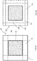
- Figure 1A shows a first example of a luminaire housing 1, the housing has an annular wall 11 surrounding a central axis 12 (shown here as an origin point) and a radially extending flange 13 around the annular wall 11.
- the radially extending flange 13 has a portion 13a that is removable from the housing.
- the portion preferably in a quick, easy and safe manner at least one cutting line 15, the at least one cutting line 15 demarcated using surface features or through holes.
- At least one clamping element 16, 16', 16" & 16'" are shown per face 17, 17', 17" & 17'" of the polygonal shape (in this example, a square is shown) that forms the annular wall 11.
- the at least one clamping element 16, 16', 16" & 16'” is provided for clamping the housing to a carrier or substrate (not shown).
- This method of attaching the luminaire housing 1 to a desired location is user friendly and may further increase the appeal of the finished lighting system. It can be seen from this element that at least one clamping element 16, 16', 16" & 16'" are provided per face 17, 17', 17" & 17'" of the square cross-sectioned annular wall 11.
- the luminaire housing 1 may remain secured in the desired location with lesser or more clamping elements 16, 16', 16" & 16'".
- the clamping elements 16, 16', 16" & 16'" could be arranged such that multiple clamping elements, for example two, are arranged on two consecutive faces 17, 17', 17" or 17'".
- the at least one clamping element 16, 16', 16" & 16'" are shown arranged alongside an outer surface of the 17, 17', 17" & 17'" of the square cross-sectioned annular wall 11 around a cavity 22 in which a lighting unit (not shown) is to be accommodated.
- the at least one clamping element 16, 16', 16" & 16'" do not extend in a radial direction past the radially extending flange 13.
- the installation of such a luminaire housing in the desired location may be a simple as selecting a suitable tool for cutting a hole in the carrier or substrate and inserting the housing 1 such that it extends through an opening in the substrate or carrier.
- the opening may be made into plasterboard, wooden, metallic or concrete material or a combination of these, for ceiling and wall applications.
- a hole-saw is commonly used to provide the opening, such a saw is mounted in a drill and then used to cut the substrate or carrier.
- a suitable size for such a hole-saw is one that has a greater diameter than the distance from the outermost surface of one clamping arrangement 16 to the outer face of a corresponding clamping arrangement 16" located opposite to the first clamping element 16, whilst being of smaller diameter than the overall width of the radially extending flange 13. The radially extending flange 13 will then sit against the carrier or substrate and is larger than the hole provided thus masking the hole that has been cut into the substrate or carrier.
- the visual appearance of the luminaire housing 1 may be further enhanced by a cover plate if desired (not shown), or as an alternative, the radially extending flange 13 may be recessed into the carrier or substrate such that the radially extending flange 13 is flush with the carrier or substrate.
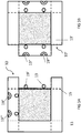
- Fig. 1B shows a side view of the first example of the luminaire 1 with a first portion 13a of a radially extending flange 13 being removed. It can also be seen in this example that at least one clamping element 16" is also being removed from the housing 1. In the example shown, an elongated foot 16a is located at the distal end of a bolt 16b.
- the at least one clamping arrangement 16, 16', 16" or 16"' may be considered to be part of the housing 1 (since it forms part of the housing 1) or it may be considered to be a separate part for fixing the (other parts of the) housing 1 to the carrier or substrate.
- the head of the bolt 16b may be accessed through a hole (not shown) in the radially extending flange 13 and tightening the bolt 16b will move the elongated foot 16a towards a main face 14 of the radially extending flange 13.
- the flange 13 also has a second main face 18 which is opposite to the first main face 14.
- the elongated foot 16a will impinge upon a face of a carrier or substrate thus tightening the main face 14 of the radially extending flange 13 against a second face of the carrier or substrate.
- the housing 1 is firmly attached to the carrier or substrate, and this preferably may all be carried out from below the carrier or substrate.
- Fig. 2A shows a view from beneath (facing the second main face 18, also considered to be the light output face) of a schematic example of a luminaire 10.
- the central region 29 may be the light exit window of the lighting unit.
- the lighting unit is inserted into housing 1 to complete the luminaire 10.
- the at least one cutting line 15 extends parallel and adjacent to the side of the square cross-sectioned housing 1.
- Fig. 2B shows a view from beneath (facing the light output face) of a schematic example of a further luminaire.
- the at least one cutting line 15 extends parallel to the side of the square cross-sectioned housing 1.
- the at least one cutting line 15 is not adjacent to the side of the square cross-sectioned housing 1. This means that when a portion 13a of the radially extending flange is removed, there will be a remaining portion 13b of the radially extending flange adjacent to the side of the square cross-sectioned housing 1.
- Fig. 3A shows a view from beneath (facing the light output face) of a schematic example of a further luminaire 10.
- the at least one cutting line 15 is adjacent and parallel to the face of the annular wall.
- the annular wall further comprises mechanical connector elements 19 & 19' and the radially extending flange 13 further comprises two mechanical connector elements 19" & 19"'.
- other configurations are possible such a single connector element 19 per face or multiple connector elements 19, 19', 19' etc. per face.
- the mechanical connector elements 19 may be formed as a male connector element, a female connector element, a hermaphroditic connector or a combination of the aforementioned types.
- the mechanical connection elements 19, 19', 19", 19'” etc. may be located in multiples on a single side and the multiples may be of the same sex, or different sexes, i.e., multiple female connectors on one face, multiple male connectors, multiple hermaphroditic connectors or they may be mixed sex, i.e., combinations of male, female and/or hermaphroditic connectors on the same face.
- the mechanical connectors may connect the lighting unit to the housing when located on the inner of the annular wall and they may connect a housing to a further housing when located on the outside of the annular wall.
- Fig. 3B shows a view from beneath (facing the light output face) of a schematic example of a corresponding further luminaire 10'. It can be seen from figures 3A and 3B that the first luminaire 10 and the further luminaire 10" are designed to cooperate with each other to create a two-lamp lighting system 100. Two portions have been removed from the radially extending flange 13 so that the first flange 13 of the first luminaire 10 and the second flange 13' of the second luminaire 10' are connectable matching parts, which in a mutually connected position form a shared flange.
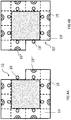
- Fig. 4A shows a view from beneath (facing the light output face) of a schematic example of a further luminaire 10.
- the male mechanical connection elements 19 are located on the side wall of the square cross-sectioned housing 1 whilst the female mechanical connection elements 19'" are part of the radially extending first flange 13.
- the example also shows that more cutting lines are possible, this allows for a more discrete removal of portions 13a from the radially extending flange 13.
- Fig. 4B shows a view from beneath (facing the light output face) of a schematic example of a corresponding further luminaire 10'.
- the male mechanical connection elements 19' are located on the side wall of the square cross-sectioned housing 1' whilst the female mechanical connection elements 19" are part of the radially extending second flange 13'.
- the example also shows that more cutting lines are possible, this allows for a more discrete removal of portions 13a from the radially extending flange 13'. This may facilitate a more aesthetically pleasing appearance or it may increase the mechanical strength of the connection between the first luminaire 10 and the second luminaire 10" when creating a lighting system 100.
- Fig. 5A shows a view from beneath (facing the light output face) of a schematic example of a further luminaire 10.
- the cutting lines 15 are adjacent and parallel to the side of the annular wall of the housing 1.
- the annular wall further comprises a male mechanical connector element 19 and a female mechanical connector element 19'" per side (i.e., four pairs of mechanical connector elements per luminaire housing 10).
- Fig. 5B shows a view from beneath (facing the light output face) of a schematic example of a corresponding further luminaire 10'.
- the cutting lines 15 are adjacent and parallel to the side of the annular wall of the housing 1'.
- the annular wall further comprises a male mechanical connector element 19' and a female mechanical connector element 19" per side (i.e., four pairs of mechanical connector elements per luminaire housing 10').
- Fig. 6A shows a view from beneath (facing the light output face) of a schematic example of a further luminaire 10.
- the cutting lines 15 are adjacent and parallel to the sides of the polygonal annular wall.
- the mechanical connector elements 19 & 19'" are preferably part of the cutting lines 15, i.e., the form the mechanical elements when the region is removed from the radially extending flange 13.
- Fig. 6B shows a view from beneath (facing the light output face) of a schematic example of a corresponding further luminaire 10'.
- the male connector element 19' and the female mechanical connector elements 19" are formed in the radially extending flange 13" of luminaire 10' when a portion is removed from the radially extending flange when cut along the demarcated cutting lines 15. This may remove additional material from the housing and may also simply the mold used for manufacturing the housings, both of these advantages may reduce the cost of the finished product.
- Fig. 7A shows a view from beneath of a schematic example of a further luminaire 10.
- the luminaire 10 has a circular cross-section orthogonal to the central axis of the luminaire.
- the radially extending flange 13 has 4 cutting lines 15 but any number of lines could be used. If the circular luminaire 10 has a greater number of cutting lines 15, more discrete regions may be removed from the radially extending flange 13 thus allowing more varied modular lighting systems 100 (shown in more detail in figures 9A and 9B .
- Fig. 7B shows a view from beneath of a schematic example of a further luminaire 10.
- the luminaire 10 has a hexagonal cross-section orthogonal to the central axis of the housing 1.
- An advantage of using luminaires 10, 10', 10", 10'” etc. having polygonal, preferably, regular polygonal cross-sectioned housings ,1, 1', 1", & 1'” etc., is the fact that they tessellate readily to offer a densely packed modular lighting system 100. If each face of the polygonal annular wall has an associated cutting line that extends fully across the radially extending flange 13, then the following equation is applicable: wherein the polygonal shape has n No. of sides then the flange is divided into 2 ⁇ n removable portions by n No. of cutting lines.
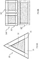
- Fig. 8A shows a view from beneath of a schematic example of a further luminaire 10.
- a luminaire having an equilateral triangular cross-section orthogonal to the central axis of the housing 1 is shown.
- the above equation is also applicable.
- Fig. 8B shows a view from beneath of a schematic embodiment of a lighting system 100 comprising a housing/luminaire group.
- a lighting system 100 comprising a housing/luminaire group.
- a rectangular luminaire 10" can be connected to two square shaped luminaires 10 & 10'.
- This variation may be used to make modular lighting systems 100 from a combination of many cross-sectionally shaped luminaires 10, 10', 10", 10'” etc. Indeed, so many combinations are possible that the installer has essentially a "free-hand" to construct a desired modular lighting system 100.
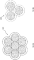
- Fig. 9A shows a view from beneath of a schematic embodiment of a further lighting system 100 comprising a further housing/luminaire group. In this figure, a hexagonally-packed circular array is shown.
- Fig. 9B shows a view from beneath of a schematic embodiment of a further lighting system 100' comprising a further housing/luminaire group.
- a further lighting system 100' comprising a further housing/luminaire group.
- an array of circular luminaires is shown, the cutting lines of the radially extending flange can be provided in such a way that the finished lighting system 100' has a decorative visible flange pattern created when the luminaires are connected together.
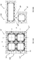
- Fig. 10A shows a view from beneath of an embodiment of a further lighting system 100 comprising a further housing/luminaire group, created from 4 square cross-section luminaires 10, 10', 10" & 10'".
- the radially extending flanges 13 have two portions (adjacent to each other) removed to allow a close-coupled square lighting system that accommodates 4 lighting units to be created.
- close-coupled is taken to mean a lighting system having a pitch X (distance between adjacent luminaire's central axes) that is smaller than an equivalent lighting system wherein the radially extending flanges 13 are not entirely removed between adjacent, connected luminaires 10, 10', 10" & 10'" (as shown in figure 11 ).
- Fig. 10B shows a view from beneath of an embodiment of a further lighting system 100 comprising a further housing/luminaire group, this embodiment is similar to that shown in figure 8B .
- a rectangular cross-sectioned luminaire 10 is mechanically connected using male and female connectors 19, 19"', 19" and 19' (the last two not shown in the interest of clarity) to a square cross-sectioned luminaire 10".
- this lighting system 100 has a relatively small pitch distance X between central axes of adjacent luminaires 10 & 10'.
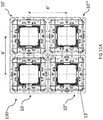
- Fig. 11A shows a view from beneath of an embodiment of a further lighting system 100 comprising a further housing/luminaire group.
- a portion of the radially extending flanges 13 remains between adjacent, connected luminaires 10, 10', 10" & 10'".
- the pitch distance X in this case will be greater for lighting system 100 comprising luminaires 10, 10', 10" & 10'" with at least a portion of the radially extending flanges 13 remaining compared to a lighting system 100 comprising identically sized luminaires 10, 10', 10" & 10'" wherein the entire portion of the radially extending flanges 13 between the adjacent connected luminaires 10, 10', 10" & 10'" are removed.
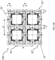
- Fig. 11B shows a view from beneath of an embodiment of a further lighting system 100 comprising a further housing/luminaire group, in this figure, a portion of the radially extending flanges 13 remain between adjacent, connected luminaires 10, 10", 10" & 10'".
- the flange remains intact on one of the luminaires per pair of luminaires, i.e., between 10 & 10" between 10 & 10', between 10" &10'" & between 10" & 10'". This results in a distance D between the annular wall on connected luminaires and leads to a greater pitch distance X than in the case of Fig. 10A but less than shown in Fig. 11A .
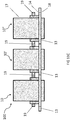
- Fig. 11C shows a cross section side view of a lighting system 100 comprising a housing/luminaire group of three connected luminaires 10, 10" & 10" in a linear arrangement.
- the annular wall 17 of the luminaire 10" can be seen extending from the radially extending flange 13. It can also be see that the annular wall 17 not only extends from the main face 14 of the radially extending flange 13 but it also extends from the second main face 18 of the radially extending flange 13.
- a lighting unit 23 is insertable alongside the axis 12 into the cavity of the housing of the respective luminaire.
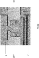
- Fig. 12 shows a close-up view of an example of the at least one mechanical connector element 19 further comprising a male mechanical connector element 19, shown as part of housing 1 and female mechanical connector element 19'" shown as part of further housing 1".
- These type of mechanical connector elements may "snap together” if pressed together in a radial direction, alternatively, they may slide together if pressed together in an axial direction.
Landscapes
- Engineering & Computer Science (AREA)
- General Engineering & Computer Science (AREA)
- Non-Portable Lighting Devices Or Systems Thereof (AREA)
- Arrangement Of Elements, Cooling, Sealing, Or The Like Of Lighting Devices (AREA)
Claims (13)
- Beleuchtungssystem (100), umfassend einen ersten Leuchtkörper (10) und einen zweiten Leuchtkörper (10'), wobei jeder von dem ersten und zweiten Leuchtkörper (10; 10') ein Gehäuse (1) und eine Beleuchtungseinheit umfasst, die in das Gehäuse (1) einsetzbar und von diesem entfernbar ist, wobei das Gehäuse (1) einen sich radial erstreckenden Flansch (13, 13') um eine ringförmige Wand (11) umfasst, wobei die ringförmige Wand (11) in einer axialen Richtung um eine zentrale Achse (120) von einer ersten Hauptfläche des sich radial erstreckenden Flansches (13; 13') vorragt, wobei das Gehäuse (1) weiter eine Klemmanordnung (16) zum Klemmen des Gehäuses (1) an einen Träger oder ein Substrat umfasst, wobei die Klemmanordnung (16) von dem Gehäuse (1) entfernbar ist, wobei der erste Leuchtkörper (10) einen ersten sich radial erstreckenden Flansch (13) mit einem ersten entfernbaren Abschnitt hat und der zweite Leuchtkörper (10') einen zweiten sich radial erstreckenden Flansch (13') mit einem zweiten entfernbaren Abschnitt hat, wobei nach Entfernen des ersten entfernbaren Abschnitts und des zweiten entfernbaren Abschnitts der erste und zweite sich radial erstreckende Flansch (13; 13') verbindbare passende Teile sind, die in wechselseitig verbundener Position einen gemeinsamen Flansch bilden.
- Beleuchtungssystem (100) nach Anspruch 1, wobei das Gehäuse (1) mehrere Klemmanordnungen umfasst und wobei eine erste Klemmanordnung entlang einer Fläche, die dem Abschnitt des sich radial erstreckenden Flansches (13; 13') am nächsten ist, der von dem Gehäuse (1) entfernbar ist, entfernbar ist.
- Beleuchtungssystem (100) nach einem der Ansprüche 1 und 2, wobei die Klemmanordnung (16) an einem entfernbaren Abschnitt des sich radial erstreckenden Flansches (13, 13') bereitgestellt ist.
- Beleuchtungssystem (100) nach einem der Ansprüche 1 bis 3, wobei jeder des ersten und zweiten Leuchtkörpers (10; 10') einen Querschnitt orthogonal zu der Mittelachse (120) hat, wobei der Querschnitt eines von einem Kreis, einer Ellipse, einem Quadrat, einem Rechteck, einem Dreieck, einem Sechseck oder einer anderen vieleckigen Form ist.
- Beleuchtungssystem (100) nach einem der Ansprüche 1 bis 4, wobei der sich radial erstreckende Flansch (13, 13') Oberflächenmerkmale oder Durchgangslöcher zum Abgrenzen mindestens einer Schnittlinie umfasst.
- Beleuchtungssystem (100) nach Anspruch 5, wobei jeder des ersten und zweiten Leuchtkörpers (10; 10') einen Querschnitt orthogonal zu der Mittelachse (120) hat, wobei der Querschnitt eine vieleckige Form ist und wobei jede Seite der vieleckigen Form eine entsprechende Schnittlinie hat, die sich angrenzend und parallel zu der Seite und über die volle Länge des sich radial erstreckenden Flansches (13; 13') an der entsprechenden Seite erstreckt.
- Beleuchtungssystem (100) nach Anspruch 6, wobei die vieleckige Form n Seiten hat und wobei der sich radial erstreckende Flansch (13; 13') durch n Schnittlinien in 2∗n entfernbare Abschnitte geteilt ist.
- Beleuchtungssystem (100) nach einem der Ansprüche 1 bis 7, wobei die ringförmige Wand (11) und/oder der sich radial erstreckende Flansch (13; 13') ein mechanisches Verbindungselement umfassen.
- Beleuchtungssystem (100) nach Anspruch 1, wobei der erste sich radial erstreckende Flansch (13), der zweite sich radial erstreckende Flansch (13') und der gemeinsame Flansch eine gleiche Breite haben, gemessen entlang einer entsprechenden virtuellen Linie durch eine entsprechende Mittelachse und sich in eine entsprechende Richtung quer zu einer entsprechenden ringförmigen Wand erstreckend.
- Verfahren zum Zusammenbauen des Beleuchtungssystems (100) nach einem der Ansprüche 1 bis 9, wobei das Verfahren die Schritte umfasst:- Entfernen eines ausgewählten ersten Abschnitts des ersten sich radial erstreckenden Flansches (13) des ersten Leuchtkörpers (10),- Entfernen einer ausgewählten ersten Klemmanordnung von dem ersten Leuchtkörper (10),- Entfernen eines ausgewählten zweiten Abschnitts des zweiten sich radial erstreckenden Flansches (13') des zweiten Leuchtkörpers (10'),- Entfernen einer ausgewählten Klemmanordnung von dem zweiten Leuchtkörper (10'),- Verbinden des ersten Leuchtkörpers (10) und des zweiten Leuchtkörpers (10'), um eine Leuchtkörpergruppe zu bilden, die geeignet ist, eine Vielzahl von Beleuchtungseinheiten zu bilden, und- Einsetzen einer entsprechenden Beleuchtungseinheit einer Vielzahl von Beleuchtungseinheiten in ein entsprechendes Gehäuse der Leuchtkörpergruppe.
- Verfahren nach Anspruch 10, wobei das Verfahren weiter umfasst:- Entfernen eines weiteren ausgewählten Abschnitts eines weiteren sich radial erstreckenden Flansches von einem weiteren Leuchtkörper,- Entfernen einer weiteren ausgewählten Klemmanordnung von dem weiteren Leuchtkörper,- Verbinden des ersten Leuchtkörpers (10), des zweiten Leuchtkörpers (10') und des weiteren Leuchtkörpers zur Bildung der Leuchtkörpergruppe.
- Verfahren nach einem der Ansprüche 10 und 11, wobei das Verfahren weiter umfasst:- Montieren der Vielzahl von Leuchtkörpern an einem Substrat oder Träger.
- Verfahren nach einem der Ansprüche 10 bis 12, wobei das Verfahren weiter die zusätzlichen früheren Schritte umfasst:- Auswählen eines ersten Leuchtkörpers (10) mit einem ersten Querschnitt orthogonal zu seiner Mittelachse,- Auswählen eines zweiten Leuchtkörpers (10') mit einem Querschnitt orthogonal zu seiner Mittelachse, wobei der zweite Querschnitt entweder gleich oder anders in Form wie der erste Querschnitt ist.
Applications Claiming Priority (3)
| Application Number | Priority Date | Filing Date | Title |
|---|---|---|---|
| EP17194432 | 2017-10-02 | ||
| EP17194585 | 2017-10-03 | ||
| PCT/EP2018/076378 WO2019068569A1 (en) | 2017-10-02 | 2018-09-28 | CONFIGURABLE AND ADJUSTABLE LUMINAIRE |
Publications (2)
| Publication Number | Publication Date |
|---|---|
| EP3692299A1 EP3692299A1 (de) | 2020-08-12 |
| EP3692299B1 true EP3692299B1 (de) | 2021-02-24 |
Family
ID=63667932
Family Applications (1)
| Application Number | Title | Priority Date | Filing Date |
|---|---|---|---|
| EP18773470.2A Active EP3692299B1 (de) | 2017-10-02 | 2018-09-28 | Konfigurierbare und anpassbare leuchte |
Country Status (4)
| Country | Link |
|---|---|
| US (1) | US11079075B2 (de) |
| EP (1) | EP3692299B1 (de) |
| CN (1) | CN111148936B (de) |
| WO (1) | WO2019068569A1 (de) |
Families Citing this family (1)
| Publication number | Priority date | Publication date | Assignee | Title |
|---|---|---|---|---|
| US12480644B2 (en) | 2023-05-17 | 2025-11-25 | Signify Holding B.V. | Configurable flat mounting frame with hanger bars |
Family Cites Families (22)
| Publication number | Priority date | Publication date | Assignee | Title |
|---|---|---|---|---|
| US3585380A (en) * | 1968-10-23 | 1971-06-15 | Kidde & Co Walter | Modular lighting fixture |
| US5660461A (en) | 1994-12-08 | 1997-08-26 | Quantum Devices, Inc. | Arrays of optoelectronic devices and method of making same |
| US5777857A (en) * | 1995-10-16 | 1998-07-07 | Cooper Industries, Inc. | Energy efficient lighting system |
| US5931432A (en) * | 1998-04-16 | 1999-08-03 | Pelco | Recessed-mounted housing |
| US7766518B2 (en) * | 2005-05-23 | 2010-08-03 | Philips Solid-State Lighting Solutions, Inc. | LED-based light-generating modules for socket engagement, and methods of assembling, installing and removing same |
| US7431482B1 (en) | 2005-06-21 | 2008-10-07 | W.A.C. Lighting Co. | Modular downlight assembly |
| GB0618295D0 (en) * | 2006-09-18 | 2006-10-25 | Bedard Sylvain | Attachment mean for recessed lighting fixtures |
| US7748868B2 (en) * | 2006-11-14 | 2010-07-06 | Focal Point, L.L.C. | Recessed luminaire |
| US7874711B2 (en) * | 2008-01-08 | 2011-01-25 | Cooper Technologies Company | Surface-mounted lighting system |
| CN101539278B (zh) * | 2008-03-19 | 2010-11-10 | 富准精密工业(深圳)有限公司 | 发光二极管组合 |
| TW201009250A (en) | 2008-08-21 | 2010-03-01 | yi-zhang Wu | Assembly-type LED lamp |
| US20120230030A1 (en) * | 2011-03-10 | 2012-09-13 | Hive Lighting, Inc. | Light Housing |
| DE102011084814A1 (de) * | 2011-10-19 | 2013-04-25 | Osram Opto Semiconductors Gmbh | Halterungselement zum halten mindestens einer flachen flächenlichtlampe, satz aus einer mehrzahl von fassungen und einer mehrzahl von langgestreckten haltekörpern und leuchte |
| US9169983B2 (en) * | 2012-04-11 | 2015-10-27 | Cree, Inc. | Overhead light fixture and related method |
| WO2014002085A1 (en) | 2012-06-26 | 2014-01-03 | M.N. Wasserman Ltd. | A modular light system |
| CN104969278B (zh) * | 2012-11-01 | 2018-02-02 | 雷斓公司 | 无缝的被照式模块化面板 |
| CN203686650U (zh) | 2013-12-17 | 2014-07-02 | 彭银水 | 一种组合式灯具 |
| GB2526144A (en) * | 2014-05-16 | 2015-11-18 | Mark Richard Stevens | Aperture liner |
| WO2017072739A1 (en) * | 2015-10-30 | 2017-05-04 | Teclite Industries Limited | A pre-formed insert body |
| CN205424701U (zh) * | 2016-03-28 | 2016-08-03 | 广州可意光电科技有限公司 | 格栅天花灯及天花灯组合结构 |
| US10054294B2 (en) * | 2016-12-16 | 2018-08-21 | Lonnie Owens | Light fixture covering assembly |
| EP3577388B1 (de) * | 2017-02-06 | 2020-07-15 | Signify Holding B.V. | Konfigurierbare und anpassbare leuchte |
-
2018
- 2018-09-28 EP EP18773470.2A patent/EP3692299B1/de active Active
- 2018-09-28 WO PCT/EP2018/076378 patent/WO2019068569A1/en not_active Ceased
- 2018-09-28 US US16/651,129 patent/US11079075B2/en active Active
- 2018-09-28 CN CN201880064470.0A patent/CN111148936B/zh active Active
Non-Patent Citations (1)
| Title |
|---|
| None * |
Also Published As
| Publication number | Publication date |
|---|---|
| WO2019068569A1 (en) | 2019-04-11 |
| CN111148936A (zh) | 2020-05-12 |
| EP3692299A1 (de) | 2020-08-12 |
| CN111148936B (zh) | 2022-11-15 |
| US20200232612A1 (en) | 2020-07-23 |
| US11079075B2 (en) | 2021-08-03 |
Similar Documents
| Publication | Publication Date | Title |
|---|---|---|
| US11428373B2 (en) | Edge lit fixture | |
| USRE50647E1 (en) | Edge lit fixture | |
| US10100988B2 (en) | Linear shelf light fixture with reflectors | |
| CN102177398B (zh) | 分布式照明系统 | |
| US11408569B2 (en) | Mounting system for retrofit light installation into existing light fixtures | |
| EP3385602B1 (de) | Modulares beleuchtungssystem | |
| US8827505B1 (en) | Lighting fixture with clip-connect diffuser base and self-retaining flexible diffuser | |
| US11079075B2 (en) | Configurable and adjustable luminaire | |
| EP3106743B1 (de) | Leuchte, modulare oberflächenabdeckanordnung und leuchtenkit | |
| US7520643B2 (en) | Lighting louver system | |
| CN107683388B (zh) | 用于照明器的可重复遮窗配件 | |
| US10859242B2 (en) | Downlight for ceiling system | |
| US20220282842A1 (en) | Coral surface lighting system | |
| KR20090005483U (ko) | 조립식 천정조명등의 코너 연결구 | |
| CN104100885A (zh) | 可拼接组合led格栅灯结构 | |
| CN104854397B (zh) | 照明条、照明系统、面板支撑元件和模块化面板系统 | |
| EP2072892B1 (de) | Lampenschirm einer Leuchtdiodenlampe (LED) | |
| CN119084880B (zh) | 一种便于拆装的铝铸件灯具壳体 | |
| USD1107989S1 (en) | Ceiling light fixture | |
| US12312806B2 (en) | Ceiling grid lighting assembly with two linear lighting modules and a configurable, functional gap | |
| JP7254966B2 (ja) | ライトガイド及びライトガイドを備える照明デバイス | |
| US20220333765A1 (en) | Configurable Ceiling Grid Lighting Assembly with T-Bar Mounting | |
| CN115111550A (zh) | 一种可快速拆装环形模块化吊灯 | |
| ITUD20090206A1 (it) | Lampada e procedimento per realizzare tale lampada | |
| KR20170052877A (ko) | 엘이디 조명등용 프레임 |
Legal Events
| Date | Code | Title | Description |
|---|---|---|---|
| STAA | Information on the status of an ep patent application or granted ep patent |
Free format text: STATUS: UNKNOWN |
|
| STAA | Information on the status of an ep patent application or granted ep patent |
Free format text: STATUS: THE INTERNATIONAL PUBLICATION HAS BEEN MADE |
|
| PUAI | Public reference made under article 153(3) epc to a published international application that has entered the european phase |
Free format text: ORIGINAL CODE: 0009012 |
|
| STAA | Information on the status of an ep patent application or granted ep patent |
Free format text: STATUS: REQUEST FOR EXAMINATION WAS MADE |
|
| 17P | Request for examination filed |
Effective date: 20200504 |
|
| AK | Designated contracting states |
Kind code of ref document: A1 Designated state(s): AL AT BE BG CH CY CZ DE DK EE ES FI FR GB GR HR HU IE IS IT LI LT LU LV MC MK MT NL NO PL PT RO RS SE SI SK SM TR |
|
| AX | Request for extension of the european patent |
Extension state: BA ME |
|
| GRAP | Despatch of communication of intention to grant a patent |
Free format text: ORIGINAL CODE: EPIDOSNIGR1 |
|
| STAA | Information on the status of an ep patent application or granted ep patent |
Free format text: STATUS: GRANT OF PATENT IS INTENDED |
|
| DAV | Request for validation of the european patent (deleted) | ||
| DAX | Request for extension of the european patent (deleted) | ||
| INTG | Intention to grant announced |
Effective date: 20201005 |
|
| GRAS | Grant fee paid |
Free format text: ORIGINAL CODE: EPIDOSNIGR3 |
|
| GRAA | (expected) grant |
Free format text: ORIGINAL CODE: 0009210 |
|
| STAA | Information on the status of an ep patent application or granted ep patent |
Free format text: STATUS: THE PATENT HAS BEEN GRANTED |
|
| AK | Designated contracting states |
Kind code of ref document: B1 Designated state(s): AL AT BE BG CH CY CZ DE DK EE ES FI FR GB GR HR HU IE IS IT LI LT LU LV MC MK MT NL NO PL PT RO RS SE SI SK SM TR |
|
| REG | Reference to a national code |
Ref country code: CH Ref legal event code: EP |
|
| REG | Reference to a national code |
Ref country code: AT Ref legal event code: REF Ref document number: 1364893 Country of ref document: AT Kind code of ref document: T Effective date: 20210315 |
|
| REG | Reference to a national code |
Ref country code: IE Ref legal event code: FG4D |
|
| REG | Reference to a national code |
Ref country code: DE Ref legal event code: R096 Ref document number: 602018013133 Country of ref document: DE |
|
| REG | Reference to a national code |
Ref country code: LT Ref legal event code: MG9D |
|
| REG | Reference to a national code |
Ref country code: NL Ref legal event code: MP Effective date: 20210224 |
|
| PG25 | Lapsed in a contracting state [announced via postgrant information from national office to epo] |
Ref country code: BG Free format text: LAPSE BECAUSE OF FAILURE TO SUBMIT A TRANSLATION OF THE DESCRIPTION OR TO PAY THE FEE WITHIN THE PRESCRIBED TIME-LIMIT Effective date: 20210524 Ref country code: HR Free format text: LAPSE BECAUSE OF FAILURE TO SUBMIT A TRANSLATION OF THE DESCRIPTION OR TO PAY THE FEE WITHIN THE PRESCRIBED TIME-LIMIT Effective date: 20210224 Ref country code: FI Free format text: LAPSE BECAUSE OF FAILURE TO SUBMIT A TRANSLATION OF THE DESCRIPTION OR TO PAY THE FEE WITHIN THE PRESCRIBED TIME-LIMIT Effective date: 20210224 Ref country code: GR Free format text: LAPSE BECAUSE OF FAILURE TO SUBMIT A TRANSLATION OF THE DESCRIPTION OR TO PAY THE FEE WITHIN THE PRESCRIBED TIME-LIMIT Effective date: 20210525 Ref country code: NO Free format text: LAPSE BECAUSE OF FAILURE TO SUBMIT A TRANSLATION OF THE DESCRIPTION OR TO PAY THE FEE WITHIN THE PRESCRIBED TIME-LIMIT Effective date: 20210524 Ref country code: PT Free format text: LAPSE BECAUSE OF FAILURE TO SUBMIT A TRANSLATION OF THE DESCRIPTION OR TO PAY THE FEE WITHIN THE PRESCRIBED TIME-LIMIT Effective date: 20210624 Ref country code: LT Free format text: LAPSE BECAUSE OF FAILURE TO SUBMIT A TRANSLATION OF THE DESCRIPTION OR TO PAY THE FEE WITHIN THE PRESCRIBED TIME-LIMIT Effective date: 20210224 |
|
| REG | Reference to a national code |
Ref country code: AT Ref legal event code: MK05 Ref document number: 1364893 Country of ref document: AT Kind code of ref document: T Effective date: 20210224 |
|
| PG25 | Lapsed in a contracting state [announced via postgrant information from national office to epo] |
Ref country code: SE Free format text: LAPSE BECAUSE OF FAILURE TO SUBMIT A TRANSLATION OF THE DESCRIPTION OR TO PAY THE FEE WITHIN THE PRESCRIBED TIME-LIMIT Effective date: 20210224 Ref country code: LV Free format text: LAPSE BECAUSE OF FAILURE TO SUBMIT A TRANSLATION OF THE DESCRIPTION OR TO PAY THE FEE WITHIN THE PRESCRIBED TIME-LIMIT Effective date: 20210224 Ref country code: PL Free format text: LAPSE BECAUSE OF FAILURE TO SUBMIT A TRANSLATION OF THE DESCRIPTION OR TO PAY THE FEE WITHIN THE PRESCRIBED TIME-LIMIT Effective date: 20210224 Ref country code: RS Free format text: LAPSE BECAUSE OF FAILURE TO SUBMIT A TRANSLATION OF THE DESCRIPTION OR TO PAY THE FEE WITHIN THE PRESCRIBED TIME-LIMIT Effective date: 20210224 Ref country code: NL Free format text: LAPSE BECAUSE OF FAILURE TO SUBMIT A TRANSLATION OF THE DESCRIPTION OR TO PAY THE FEE WITHIN THE PRESCRIBED TIME-LIMIT Effective date: 20210224 |
|
| PG25 | Lapsed in a contracting state [announced via postgrant information from national office to epo] |
Ref country code: IS Free format text: LAPSE BECAUSE OF FAILURE TO SUBMIT A TRANSLATION OF THE DESCRIPTION OR TO PAY THE FEE WITHIN THE PRESCRIBED TIME-LIMIT Effective date: 20210624 |
|
| PG25 | Lapsed in a contracting state [announced via postgrant information from national office to epo] |
Ref country code: CZ Free format text: LAPSE BECAUSE OF FAILURE TO SUBMIT A TRANSLATION OF THE DESCRIPTION OR TO PAY THE FEE WITHIN THE PRESCRIBED TIME-LIMIT Effective date: 20210224 Ref country code: EE Free format text: LAPSE BECAUSE OF FAILURE TO SUBMIT A TRANSLATION OF THE DESCRIPTION OR TO PAY THE FEE WITHIN THE PRESCRIBED TIME-LIMIT Effective date: 20210224 Ref country code: AT Free format text: LAPSE BECAUSE OF FAILURE TO SUBMIT A TRANSLATION OF THE DESCRIPTION OR TO PAY THE FEE WITHIN THE PRESCRIBED TIME-LIMIT Effective date: 20210224 Ref country code: SM Free format text: LAPSE BECAUSE OF FAILURE TO SUBMIT A TRANSLATION OF THE DESCRIPTION OR TO PAY THE FEE WITHIN THE PRESCRIBED TIME-LIMIT Effective date: 20210224 |
|
| REG | Reference to a national code |
Ref country code: DE Ref legal event code: R097 Ref document number: 602018013133 Country of ref document: DE |
|
| PG25 | Lapsed in a contracting state [announced via postgrant information from national office to epo] |
Ref country code: DK Free format text: LAPSE BECAUSE OF FAILURE TO SUBMIT A TRANSLATION OF THE DESCRIPTION OR TO PAY THE FEE WITHIN THE PRESCRIBED TIME-LIMIT Effective date: 20210224 Ref country code: SK Free format text: LAPSE BECAUSE OF FAILURE TO SUBMIT A TRANSLATION OF THE DESCRIPTION OR TO PAY THE FEE WITHIN THE PRESCRIBED TIME-LIMIT Effective date: 20210224 Ref country code: RO Free format text: LAPSE BECAUSE OF FAILURE TO SUBMIT A TRANSLATION OF THE DESCRIPTION OR TO PAY THE FEE WITHIN THE PRESCRIBED TIME-LIMIT Effective date: 20210224 |
|
| PLBE | No opposition filed within time limit |
Free format text: ORIGINAL CODE: 0009261 |
|
| STAA | Information on the status of an ep patent application or granted ep patent |
Free format text: STATUS: NO OPPOSITION FILED WITHIN TIME LIMIT |
|
| PG25 | Lapsed in a contracting state [announced via postgrant information from national office to epo] |
Ref country code: AL Free format text: LAPSE BECAUSE OF FAILURE TO SUBMIT A TRANSLATION OF THE DESCRIPTION OR TO PAY THE FEE WITHIN THE PRESCRIBED TIME-LIMIT Effective date: 20210224 Ref country code: ES Free format text: LAPSE BECAUSE OF FAILURE TO SUBMIT A TRANSLATION OF THE DESCRIPTION OR TO PAY THE FEE WITHIN THE PRESCRIBED TIME-LIMIT Effective date: 20210224 |
|
| 26N | No opposition filed |
Effective date: 20211125 |
|
| PG25 | Lapsed in a contracting state [announced via postgrant information from national office to epo] |
Ref country code: IT Free format text: LAPSE BECAUSE OF FAILURE TO SUBMIT A TRANSLATION OF THE DESCRIPTION OR TO PAY THE FEE WITHIN THE PRESCRIBED TIME-LIMIT Effective date: 20210224 |
|
| REG | Reference to a national code |
Ref country code: CH Ref legal event code: PL |
|
| REG | Reference to a national code |
Ref country code: BE Ref legal event code: MM Effective date: 20210930 |
|
| PG25 | Lapsed in a contracting state [announced via postgrant information from national office to epo] |
Ref country code: IS Free format text: LAPSE BECAUSE OF FAILURE TO SUBMIT A TRANSLATION OF THE DESCRIPTION OR TO PAY THE FEE WITHIN THE PRESCRIBED TIME-LIMIT Effective date: 20210624 Ref country code: MC Free format text: LAPSE BECAUSE OF FAILURE TO SUBMIT A TRANSLATION OF THE DESCRIPTION OR TO PAY THE FEE WITHIN THE PRESCRIBED TIME-LIMIT Effective date: 20210224 |
|
| PG25 | Lapsed in a contracting state [announced via postgrant information from national office to epo] |
Ref country code: LU Free format text: LAPSE BECAUSE OF NON-PAYMENT OF DUE FEES Effective date: 20210928 Ref country code: IE Free format text: LAPSE BECAUSE OF NON-PAYMENT OF DUE FEES Effective date: 20210928 Ref country code: BE Free format text: LAPSE BECAUSE OF NON-PAYMENT OF DUE FEES Effective date: 20210930 |
|
| PG25 | Lapsed in a contracting state [announced via postgrant information from national office to epo] |
Ref country code: LI Free format text: LAPSE BECAUSE OF NON-PAYMENT OF DUE FEES Effective date: 20210930 Ref country code: CH Free format text: LAPSE BECAUSE OF NON-PAYMENT OF DUE FEES Effective date: 20210930 |
|
| P01 | Opt-out of the competence of the unified patent court (upc) registered |
Effective date: 20230425 |
|
| PG25 | Lapsed in a contracting state [announced via postgrant information from national office to epo] |
Ref country code: CY Free format text: LAPSE BECAUSE OF FAILURE TO SUBMIT A TRANSLATION OF THE DESCRIPTION OR TO PAY THE FEE WITHIN THE PRESCRIBED TIME-LIMIT Effective date: 20210224 |
|
| PG25 | Lapsed in a contracting state [announced via postgrant information from national office to epo] |
Ref country code: HU Free format text: LAPSE BECAUSE OF FAILURE TO SUBMIT A TRANSLATION OF THE DESCRIPTION OR TO PAY THE FEE WITHIN THE PRESCRIBED TIME-LIMIT; INVALID AB INITIO Effective date: 20180928 |
|
| PG25 | Lapsed in a contracting state [announced via postgrant information from national office to epo] |
Ref country code: SI Free format text: LAPSE BECAUSE OF FAILURE TO SUBMIT A TRANSLATION OF THE DESCRIPTION OR TO PAY THE FEE WITHIN THE PRESCRIBED TIME-LIMIT Effective date: 20210224 |
|
| PG25 | Lapsed in a contracting state [announced via postgrant information from national office to epo] |
Ref country code: MK Free format text: LAPSE BECAUSE OF FAILURE TO SUBMIT A TRANSLATION OF THE DESCRIPTION OR TO PAY THE FEE WITHIN THE PRESCRIBED TIME-LIMIT Effective date: 20210224 |
|
| PG25 | Lapsed in a contracting state [announced via postgrant information from national office to epo] |
Ref country code: TR Free format text: LAPSE BECAUSE OF FAILURE TO SUBMIT A TRANSLATION OF THE DESCRIPTION OR TO PAY THE FEE WITHIN THE PRESCRIBED TIME-LIMIT Effective date: 20210224 |
|
| PG25 | Lapsed in a contracting state [announced via postgrant information from national office to epo] |
Ref country code: MT Free format text: LAPSE BECAUSE OF FAILURE TO SUBMIT A TRANSLATION OF THE DESCRIPTION OR TO PAY THE FEE WITHIN THE PRESCRIBED TIME-LIMIT Effective date: 20210224 |
|
| PGFP | Annual fee paid to national office [announced via postgrant information from national office to epo] |
Ref country code: GB Payment date: 20250923 Year of fee payment: 8 |
|
| PGFP | Annual fee paid to national office [announced via postgrant information from national office to epo] |
Ref country code: FR Payment date: 20250925 Year of fee payment: 8 |
|
| PGFP | Annual fee paid to national office [announced via postgrant information from national office to epo] |
Ref country code: DE Payment date: 20251126 Year of fee payment: 8 |