EP3691828B1 - Apparatus and method for machining a workpiece with a laser beam - Google Patents
Apparatus and method for machining a workpiece with a laser beam Download PDFInfo
- Publication number
- EP3691828B1 EP3691828B1 EP18780129.5A EP18780129A EP3691828B1 EP 3691828 B1 EP3691828 B1 EP 3691828B1 EP 18780129 A EP18780129 A EP 18780129A EP 3691828 B1 EP3691828 B1 EP 3691828B1
- Authority
- EP
- European Patent Office
- Prior art keywords
- workpiece
- machining
- laser
- unit
- laser beam
- Prior art date
- Legal status (The legal status is an assumption and is not a legal conclusion. Google has not performed a legal analysis and makes no representation as to the accuracy of the status listed.)
- Active
Links
Images


Classifications
-
- B—PERFORMING OPERATIONS; TRANSPORTING
- B05—SPRAYING OR ATOMISING IN GENERAL; APPLYING FLUENT MATERIALS TO SURFACES, IN GENERAL
- B05B—SPRAYING APPARATUS; ATOMISING APPARATUS; NOZZLES
- B05B12/00—Arrangements for controlling delivery; Arrangements for controlling the spray area
- B05B12/004—Arrangements for controlling delivery; Arrangements for controlling the spray area comprising sensors for monitoring the delivery, e.g. by displaying the sensed value or generating an alarm
-
- B—PERFORMING OPERATIONS; TRANSPORTING
- B05—SPRAYING OR ATOMISING IN GENERAL; APPLYING FLUENT MATERIALS TO SURFACES, IN GENERAL
- B05B—SPRAYING APPARATUS; ATOMISING APPARATUS; NOZZLES
- B05B12/00—Arrangements for controlling delivery; Arrangements for controlling the spray area
- B05B12/08—Arrangements for controlling delivery; Arrangements for controlling the spray area responsive to condition of liquid or other fluent material to be discharged, of ambient medium or of target ; responsive to condition of spray devices or of supply means, e.g. pipes, pumps or their drive means
- B05B12/082—Arrangements for controlling delivery; Arrangements for controlling the spray area responsive to condition of liquid or other fluent material to be discharged, of ambient medium or of target ; responsive to condition of spray devices or of supply means, e.g. pipes, pumps or their drive means responsive to a condition of the discharged jet or spray, e.g. to jet shape, spray pattern or droplet size
-
- B—PERFORMING OPERATIONS; TRANSPORTING
- B23—MACHINE TOOLS; METAL-WORKING NOT OTHERWISE PROVIDED FOR
- B23K—SOLDERING OR UNSOLDERING; WELDING; CLADDING OR PLATING BY SOLDERING OR WELDING; CUTTING BY APPLYING HEAT LOCALLY, e.g. FLAME CUTTING; WORKING BY LASER BEAM
- B23K26/00—Working by laser beam, e.g. welding, cutting or boring
- B23K26/02—Positioning or observing the workpiece, e.g. with respect to the point of impact; Aligning, aiming or focusing the laser beam
- B23K26/03—Observing, e.g. monitoring, the workpiece
-
- B—PERFORMING OPERATIONS; TRANSPORTING
- B23—MACHINE TOOLS; METAL-WORKING NOT OTHERWISE PROVIDED FOR
- B23K—SOLDERING OR UNSOLDERING; WELDING; CLADDING OR PLATING BY SOLDERING OR WELDING; CUTTING BY APPLYING HEAT LOCALLY, e.g. FLAME CUTTING; WORKING BY LASER BEAM
- B23K26/00—Working by laser beam, e.g. welding, cutting or boring
- B23K26/02—Positioning or observing the workpiece, e.g. with respect to the point of impact; Aligning, aiming or focusing the laser beam
- B23K26/03—Observing, e.g. monitoring, the workpiece
- B23K26/032—Observing, e.g. monitoring, the workpiece using optical means
-
- B—PERFORMING OPERATIONS; TRANSPORTING
- B23—MACHINE TOOLS; METAL-WORKING NOT OTHERWISE PROVIDED FOR
- B23K—SOLDERING OR UNSOLDERING; WELDING; CLADDING OR PLATING BY SOLDERING OR WELDING; CUTTING BY APPLYING HEAT LOCALLY, e.g. FLAME CUTTING; WORKING BY LASER BEAM
- B23K26/00—Working by laser beam, e.g. welding, cutting or boring
- B23K26/14—Working by laser beam, e.g. welding, cutting or boring using a fluid stream, e.g. a jet of gas, in conjunction with the laser beam; Nozzles therefor
- B23K26/146—Working by laser beam, e.g. welding, cutting or boring using a fluid stream, e.g. a jet of gas, in conjunction with the laser beam; Nozzles therefor the fluid stream containing a liquid
-
- B—PERFORMING OPERATIONS; TRANSPORTING
- B23—MACHINE TOOLS; METAL-WORKING NOT OTHERWISE PROVIDED FOR
- B23K—SOLDERING OR UNSOLDERING; WELDING; CLADDING OR PLATING BY SOLDERING OR WELDING; CUTTING BY APPLYING HEAT LOCALLY, e.g. FLAME CUTTING; WORKING BY LASER BEAM
- B23K26/00—Working by laser beam, e.g. welding, cutting or boring
- B23K26/14—Working by laser beam, e.g. welding, cutting or boring using a fluid stream, e.g. a jet of gas, in conjunction with the laser beam; Nozzles therefor
- B23K26/1462—Nozzles; Features related to nozzles
-
- B—PERFORMING OPERATIONS; TRANSPORTING
- B23—MACHINE TOOLS; METAL-WORKING NOT OTHERWISE PROVIDED FOR
- B23K—SOLDERING OR UNSOLDERING; WELDING; CLADDING OR PLATING BY SOLDERING OR WELDING; CUTTING BY APPLYING HEAT LOCALLY, e.g. FLAME CUTTING; WORKING BY LASER BEAM
- B23K26/00—Working by laser beam, e.g. welding, cutting or boring
- B23K26/70—Auxiliary operations or equipment
- B23K26/702—Auxiliary equipment
- B23K26/707—Auxiliary equipment for monitoring laser beam transmission optics
-
- B—PERFORMING OPERATIONS; TRANSPORTING
- B23—MACHINE TOOLS; METAL-WORKING NOT OTHERWISE PROVIDED FOR
- B23K—SOLDERING OR UNSOLDERING; WELDING; CLADDING OR PLATING BY SOLDERING OR WELDING; CUTTING BY APPLYING HEAT LOCALLY, e.g. FLAME CUTTING; WORKING BY LASER BEAM
- B23K26/00—Working by laser beam, e.g. welding, cutting or boring
- B23K26/14—Working by laser beam, e.g. welding, cutting or boring using a fluid stream, e.g. a jet of gas, in conjunction with the laser beam; Nozzles therefor
- B23K26/1462—Nozzles; Features related to nozzles
- B23K26/1464—Supply to, or discharge from, nozzles of media, e.g. gas, powder, wire
- B23K26/1476—Features inside the nozzle for feeding the fluid stream through the nozzle
Definitions
- the present invention relates to an apparatus for machining a workpiece with a laser beam, and to a corresponding machining method.
- the apparatus and method are for machining the workpiece with a laser beam coupled into a fluid jet.
- the present invention specifically relates to controlling the machining process of the apparatus and the method based on a process emission of secondary radiation.
- a conventional apparatus for machining a workpiece with a laser beam is known. Also a conventional apparatus for machining a workpiece with a laser beam coupled into a fluid jet, wherein the fluid jet impinges onto the workpiece, is generally known.
- a problem typically encountered during the laser beam machining process of a conventional apparatus is that, due to the lack of mechanical interactions of the apparatus with the workpiece, it is difficult to determine characteristic states of the process of machining the workpiece. This difficulty often leads to a significant increase of the machining process time. For example, when a conventional apparatus is used to cut a workpiece with the laser beam, it is problematic to accurately determine, if and when the laser beam has broken through the workpiece material. Thus, the cutting process cannot be finished in a time-optimized manner. Additionally, it would also be beneficial to have the possibility to accurately determine other states of machining the workpiece, for example, states that indicate an instability of the machining process.
- the laser beam may be scattered back from the workpiece in an uncontrolled manner, a determination of the process state by visual inspection of the workpiece is difficult or even dangerous.
- the conventional apparatus uses a laser beam guided in a fluid jet, additional difficulties arise due to the wet workpiece environment. For instance, since the fluid jet may splatter back from the workpiece in an uncontrolled manner, the fluid may accumulate on surface regions of the workpiece, thereby making it even more difficult to determine states of the machining process.
- the present invention aims at improving the conventional apparatus and solutions. It is accordingly an object of the present invention to provide an apparatus and a method for machining a workpiece with a laser beam coupled into a fluid jet, which allow reducing the machining process time.
- the invention should allow determining more precisely a state of the machining process. The higher the accuracy of determining the state of machining the workpiece is, the better the machining process can be time-optimized.
- the invention desires a reliable determination of whether the laser beam has broken through the workpiece material or not.
- the present invention thereby aims particularly for a compact apparatus and a solution, which is not disturbed by the wet environment caused by the fluid jet. Accordingly, damages to the apparatus and equipment should be avoided.
- US 2017/0157709 A1 describes an apparatus for determining a spatial position of a liquid jet, in particular a liquid jet for optically guiding a laser beam, through the modification of an orientation.
- WO 2016/194071 A1 discloses a machine tool that performs machining while ejecting a pressurized liquid toward a workpiece.
- US 2015/0209900 A1 describes a method for determining hole completion in laser drilling of an article of manufacture with a laser beam that is directed inside a fluid column.
- US 2016/199941 A1 discloses a method and system for confined laser drilling with a laser beam within a liquid column.
- WO 2012/031009 A1 discloses high power lasers systems, apparatus and methods for performing laser operations, in particular, in environments where an optically obstructive medium is present in the laser beam path, such as within a borehole of an oil, gas, or geothermal well.
- the present invention proposes detecting a state of machining the workpiece based on a process emission, i.e. based on a laser-induced electromagnetic radiation that results from the machining of the workpiece with the laser beam.
- a first aspect of the present invention provides an apparatus for machining a workpiece according to claim 1.
- the laser beam is coupled into the pressurized fluid jet, which acts like a waveguide for the laser beam and guides the laser beam onto the workpiece by means of total internal reflection.
- the pressurized fluid jet is preferably provided by a fluid nozzle, and the laser beam may be directed by the at least one optical element through the fluid nozzle into the fluid jet and towards the workpiece.
- the fluid nozzle and the at least one optical element may be separated, for instance by an optical window, in order to prevent contact of the optical element and the fluid.
- the spectral separation unit is arranged and configured to receive the laser-induced electromagnetic radiation propagating away from the workpiece, and separates the electromagnetic radiation of interest from the received radiation, and may provide the radiation of interest including the at least part of said secondary radiation to the sensing unit.
- the spectral separation unit has the effect that the state of machining the workpiece can be determined even more accurately and more reliably.
- the spectral separation unit prevents that unwanted radiation reaches the sensing unit.
- the sensing unit can therefore more sensitively and accurately detect the radiation of interest.
- the radiation of interest may be the secondary radiation with unwanted other radiation removed, or may be a part of the secondary radiation. It may, for instance, be that the laser beam induces different kinds of electromagnetic radiation caused by different mechanisms. In this case, the radiation of interest may be only secondary radiation caused by one specific mechanism.
- the secondary radiation is specifically caused by the processing of the workpiece with the laser beam, for instance, because the machined surface region of the workpiece is transformed into a plasma.
- This plasma emits a characteristic radiation, which can be easily isolated on the sensing unit by means of the spectral separation unit, in order to allow a particularly accurate determination of the state of machining the workpiece, especially of whether the laser beam broke through the workpiece.
- the sensing unit may be a photo-detecting device or light sensor, and is configured to detect the secondary radiation included in the laser-induced radiation that travels along the fluid jet in the direction opposite to the primary laser beam, i.e. propagates away from the workpiece. Notably, some electromagnetic radiation induced by the laser beam machining the workpiece may not back-propagate through the fluid jet, but may travel elsewhere.
- the secondary radiation received by the sensing unit provides a very accurate fingerprint of different states of machining the workpiece.
- the signal which is accordingly output by the sensing unit, shows characteristic behaviors depending on the different states of machining the workpiece. Therefore, the signal processing unit is able to accurately and efficiently determine states of machining the workpiece based on the signal. As a consequence, it may trigger according actions of the apparatus based on the determined state, in order to significantly improve the machining process time.
- the fluid jet allows arranging the sensing unit safe from the wet environment of the machining process.
- the fluid jet acts as a waveguide also for back-propagating laser-induced radiation, and thus allows a more accurate detection of the secondary radiation included in this laser-induced radiation, and consequently an analysis or post-processing of the signal that the sensing unit supplies when sensing this secondary radiation.
- the sensing unit is housed in the apparatus, more preferably such that it is separated from any fluid circuitry and the fluid nozzle, in order to be protected from fluid contact and thus enjoy an increased lifetime.
- the apparatus of the first aspect can be built in a very compact manner, and all components of the apparatus may advantageously be integrated.
- Integrating the signal over time improves further the reliability of determining the state of machining the workpiece.
- patterns that occur in a single (non-integrated) signal can be enhanced in the integrated signal.
- additional patterns that appear only in the integrated signal may allow determining further states, or determining the states more precisely.
- the sensitivity of the determination is generally enhanced, since the signal noise impact is reduced.
- the signal processing unit is configured to determine, as the state of machining the workpiece, whether the laser beam has broken through the workpiece.
- the apparatus of the invention can particularly determine very accurately and quickly, whether the laser beam has broken through the workpiece. Accordingly, the machining process time can be significantly reduced, particularly when the apparatus is used for cutting a workpiece with the laser beam. This is due to the fact that the machining process can be stopped immediately, once the state that the laser beam has broken through the workpiece is determined.
- the signal processing unit may be configured to automatically provide such an instruction.
- the spectral separation unit is arranged to receive the laser-induced electromagnetic radiation propagating through the fluid jet through the at least one optical element, which is configured to couple the laser beam into the fluid jet.
- the apparatus can be built particularly compact. Furthermore, the least amount of optical components are required.
- the apparatus may comprises an optical head including the machining unit and the sensing unit. Accordingly, in the optical head the laser beam can be coupled by the machining unit into the fluid jet, and the sensing unit may sense the secondary radiation included in the laser-induced radiation back-propagating from the workpiece.
- the signal processing unit may in this case be arranged in the apparatus, e.g. in a housing thereof, but outside the optical head.
- a laser unit comprising laser source and/or laser controller may be part of the apparatus or not, but is at least separate from the optical head.
- the apparatus comprises an optical head including the machining unit, and a laser unit including the spectral separation unit and the sensing unit.
- the laser unit may comprise laser source and/or laser controller.
- the laser beam may be provided by the laser unit to the optical head, where it is coupled into the fluid jet by the machining unit.
- Laser-induced radiation back-propagating from the workpiece may be guided through the optical head to the laser unit, where it is received by the spectral separation unit.
- the optical head can be optically connected to the laser unit, for instance, by an optical fiber.
- the state of machining the workpiece can be determined precisely by the signal processing unit based on the signal, which is provided by the sensing unit based on the received secondary radiation, even when the sensing unit is arranged in the laser unit, i.e. distanced from the optical head.
- An advantage of having the spectral separation unit and the sensing unit, and optionally associated optical elements like a beam splitter and/or focusing optics etc., provided in the laser unit is that the handling of these elements, and e.g. their maintenance or replacement, becomes easier.
- the optical head can be exchanged without having to exchange the sensing unit and associated optical elements.
- the optical head can also be built smaller, and the sensing unit and associated optical elements can be built larger, due to more space available in the laser unit.
- the apparatus further comprises an optical connection element, particularly an optical fiber, for optically connecting the optical head and the laser unit, wherein the machining unit in the optical head is configured to receive the laser beam via the optical connection element, and the spectral separation unit in the laser unit is configured to receive the laser-induced electromagnetic radiation via the optical connection element.
- an optical connection element particularly an optical fiber
- the same optical connection element e.g. optical fiber
- the same optical connection element is used to transport the laser light for the laser beam and the laser-induced radiation, respectively, within the apparatus, i.e. between the optical head and the laser unit.
- the state of machining the workpiece can be accurately determined by the processing unit based on the signal produced accordingly by the sensing unit.
- the at least one optical element includes a lens for coupling the laser beam into the fluid jet, and the spectral separation unit is arranged to receive the back-propagating laser-induced electromagnetic radiation through said lens.
- This specific implementation form therefore allows using the lens in a double manner and allows positioning the sensing unit such that it is protected from fluid contact. Further, the apparatus can be built in a compact manner.
- the spectral separation unit is used to filter out any unwanted laser-induced electromagnetic radiation, and to focus only the secondary radiation emitted from a portion of the workpiece that is machined with the laser beam, onto the sensing unit.
- the signal processing unit is configured to process the signal with a temporal resolution of below 0.5s, preferably of below 0.1s.
- the temporal resolution of the signal processing unit may be between 0.2-0.5s, or between 0.1-0.5s, or between 0.1-0.2s, or even between 0.01s-0.1s.
- These preferred temporal resolutions provided by the signal processing unit allow an accurate detection of the state of machining the workpiece, and thus a particularly stable control of the machining process. In particular, the machining process time can be reduced even further with such a signal processing unit.
- the apparatus further comprises at least one peripheral device, preferably a laser controller, fluid supply controller, gas supply controller, and/or movement axes controller, wherein the signal processing unit is configured to provide the at least one peripheral device with an instruction signal based on the determined state of machining the workpiece, in order to start, break, stop and/or restart an action of the peripheral device.
- the machining process time can be optimized.
- the apparatus can react quickly to take the necessary actions. For instance, if the laser beam broke through the workpiece, the apparatus can stop the machining process. As a further advantage, the machining process quality can be improved.
- a second aspect of the present invention provides a method of machining a workpiece according to claim 9.
- the method further comprises, for determining the state of machining the workpiece, recording a plurality of signals, comparing the recorded signals with predetermined reference signals, and determining the state of machining the workpiece based on similar or matching reference signals.
- the method comprises determining, as the state of machining the workpiece, that the laser beam has broken through the workpiece, when a value of a single signal or the integrated signal, which increased after a start of machining the workpiece, decreases again below a determined threshold value.
- FIG. 1 shows an apparatus 100 according to an example.
- the apparatus 100 is configured to machine a workpiece 101 with a laser beam 102.
- the workpiece 101 may be a made of a material including, for example, metals, ceramics, diamonds, semiconductors, carbides, alloys, superalloys, or ultra-hard materials.
- the workpiece 101 is notably not a part of the apparatus 100.
- the workpiece 101 can be positioned on a machining surface, which may or may not be part of the apparatus 100.
- the apparatus 100 can be arranged such that it can machine the workpiece 101 disposed on the machining surface.
- the apparatus 100 may also control movements of the machining surface in up to three dimensions.
- the apparatus 100 comprises a machining unit 103, a sensing unit 107, and a signal processing unit 109. These units 103, 107 and 109 of the apparatus 100 are preferably all integrated into the apparatus 100, i.e. they are preferably disposed within a housing or enclosure of the apparatus 100. The apparatus 100 may also comprise further units also disposed within the same housing or enclosure.
- the machining unit 103 is configured to provide a pressurized fluid jet 104 onto the workpiece 101, and to couple the laser beam 102 into the fluid jet 104.
- the laser beam 102 is coupled into the fluid jet 104 by means of at least one optical element 105.
- This at least one optical element 105 may include, for example, one or more lenses, lens assemblies, light guiding optics, beam splitters, mirrors, filters, or polarizers.
- the laser beam 102 is guided by the preferably thin (i.e. having a diameter in the ⁇ m range) fluid jet 104, in principle like it would be guided in an optical fiber.
- the laser beam 102 is a pulsed laser beam 102 and is directed towards and onto the workpiece 101, and can thus be used to precisely machine the workpiece 101, while the fluid jet 104 continually cools the workpiece 101 and potentially removes debris.
- the apparatus 100 may specifically be configured to accurately cut or shape the workpiece 101.
- the laser beam 102 is provided by a laser, which may be a part of the apparatus or which may be external but couple the laser beam 102 into a laser supply port of the apparatus 100.
- the laser beam 102 may be visible, and is preferably from the green spectrum.
- the laser beam 102 may have a wavelength of 532 nm.
- the sensing unit 107 is arranged to receive laser-induced electromagnetic radiation 106, i.e. an electromagnetic emission that occurs when the workpiece 101 is machined with the laser beam 102.
- the laser-induced electromagnetic radiation 106 may also be referred to as "process emission”.
- the sensing unit 107 is arranged such that it can receive, and thus sense, the laser-induced electromagnetic radiation 106 propagating away from the workpiece 101 through the fluid jet 104 and through at least one optical element. Accordingly, the back-propagating process emission 106 can reach the sensing unit 107 guided in and by the fluid jet 104.
- the at least one optical element, through which the sensing unit 107 can receive the process emission 106 can be the at least one optical element 105, which is used to couple the laser beam 102 into the fluid jet 104. This is exemplarily shown in FIG. 1 .
- the sensing unit 107 is further configured to convert the received laser-induced electromagnetic radiation 106 into a signal 108, for instance, it provides a photo current as output signal.
- the sensing unit 107 may thus, for example, be a photodetector, but it can also be any other device or light sensor that is able to convert at least the electromagnetic radiation of interest into an electrical signal.
- the signal 108 is provided to the signal processing unit 109 for further analysis and/or processing.
- the signal processing unit 109 is, for example, realized by a microprocessor or computer, and is specifically configured to determine a state of machining the workpiece 101 based on the signal 108, which it receives from the sensing unit 107.
- the signal processing unit 109 is configured to determine, as the state of machine the workpiece 101, whether the laser beam 102 has broken through the workpiece 101. In other words, it can determine that and when the laser beam 102 breaks through the workpiece 101.
- the signal processing unit 109 may apply signal processing on the signal 108.
- Signal processing may include, for example, scaling, averaging, recording over time, integrating over time, or converting the signal 108, and may include comparing the signal 108 or an integrated signal with one or more reference signals.
- the signal processing unit 109 may be configured to record a plurality of signals 108, and to compare the recorded signals 108 with pre-stored reference signals.
- the signal processing unit 109 is configured to integrate a plurality of signals 108 over time to produce an integrated signal, and to evaluate a pattern or a change of a pattern in the integrated signal.
- the plurality of signals 108 arise from laser-pulse induced electromagnetic radiation 106 sensed by the sensing unit 107, as the laser beam 102 is a pulsed laser beam.
- the signal processing unit 109 may then be configured to determine the state of machining the workpiece 101 based on similar or matching reference signals (in the first case) or based on the pattern or the change of the pattern (in the second case).
- the signal processing unit 109 provides a temporal resolution of below 0.5s, preferably of below 0.2s, more preferably of below 0.1s, since preferably the sensing unit 107 is operated with at least 10Hz, more preferably with at least 15 Hz.
- FIG. 2 shows an apparatus 200 according to an embodiment of the present invention, which builds on the apparatus 100 shown in FIG. 1 .
- the apparatus 200 of FIG. 2 includes the machining unit 103, which is configured to provide the pressurized fluid jet 104 onto the workpiece 101, and to couple the laser beam 102 into the fluid jet 104.
- the sensing unit 107 which is configured to receive secondary radiation that is included in a back-propagating laser-induced electromagnetic radiation 106 via the fluid jet 104 and through the machining unit 103, preferably through the at least one optical element 105, and to convert the secondary radiation into the signal 108.
- the signal processing unit 109 (here referred to as "Digital signal processing unit + IPC", i.e. the signal processing unit 109 may also provide inter-process communications (IPC)) is again configured to determine a state of machine the workpiece 101 based on the signal 108.
- FIG. 2 additionally shows further details about the preferred overall layout of the apparatus 200.
- the apparatus 200 of FIG. 2 especially includes several peripheral devices.
- the apparatus 200 may include a laser source 221 and a laser controller 207 for controlling the laser source 221.
- the laser source 221 is configured to supply 204 the laser light for the laser beam 102.
- the laser source 221 may also be an external device not included in the apparatus 200 but for supplying 204 the laser light to a laser supply port of the apparatus 200.
- the laser beam 102 is preferably directed by an optical unit 201 of the apparatus 200, which is preferably a beam splitter and preferably arranged in the optical path between the machining unit 103 and the sensing unit 107, towards the machining unit 103.
- the laser beam 102 is coupled into the fluid jet 104.
- the back-propagating laser-induced electromagnetic radiation 106 passes preferably through this optical unit 201, but is directed towards the sensing unit 107.
- the apparatus 200 includes also a spectral separation unit 202, which is configured to isolate only electromagnetic radiation of interest 203 including the secondary radiation 206a on the sensing unit 107.
- the spectral separation unit 202 is arranged in the optical path between the machining unit 103 and the sensing unit 107, such that it can receive the laser-induced electromagnetic radiation 106 travelling away from the workpiece 101 through the fluid jet 104 and through the at least one optical element 105, and can output the radiation of interest 203, which includes at least a part of secondary radiation 206a included in the received laser-induced electromagnetic radiation 106, onto the sensing unit 107.
- the spectral separation unit 202 may be an optical filter unit, which may consist of one or more optical filters and is configured to filter out unwanted electromagnetic radiation, i.e.
- the electromagnetic radiation of interest 203 may particularly be only the secondary radiation206a, wherein other electromagnetic radiation that accidently reaches the spectral separation unit 202 (and would reach the sensing unit 107 without the spectral separation unit 202) is filtered out.
- the electromagnetic radiation of interest 203 is also be a part of the laser-induced electromagnetic radiation 106 that reaches the spectral separation unit 202 (and would reach the sensing unit 107 without the spectral separation unit 202), wherein laser-induced electromagnetic radiation that is not of interest is filtered out. In the embodiment of FIG.
- the laser-induced electromagnetic radiation includes secondary radiation
- the spectral separation unit 202 is configured to prevent laser light reaching the sensing unit 107. That is, the spectral separation unit 202 is configured to filter out light of the same wavelength than provided by the laser source 221.
- the laser-induced electromagnetic radiation 106 includes the secondary radiation 206a that is emitted from the portion of the workpiece 101 that is machined with the laser beam 102.
- the machined surface portion of the workpiece 101 may, for instance, be transformed into a plasma by the laser beam 102, which plasma is the source of the secondary radiation 206a.
- this secondary radiation 206a is from the yellow and/or orange spectrum.
- the spectral separation unit 202 may in this case be configured to allow light from the yellow and/or orange spectrum to reach the sensing unit 107, while it blocks light from other parts of the spectrum, especially blocks the laser light e.g. from the green spectrum.
- the radiation of interest 203 includes only the secondary radiation 206a.
- the sensing unit 107 can in this case be configured to be particularly sensitive to the yellow and/or orange spectrum.
- the laser-induced electromagnetic radiation 106 could also be or include primary laser radiation 206b reflected from the workpiece 101, especially from the workpiece surface.
- the spectral separation unit 202 may in this case be configured to allow light from the green spectrum to reach the sensing unit 107, while it blocks light from other parts of the spectrum.
- the radiation of interest 203 may include only the secondary radiation 206b.
- the sensing unit 107 can in this case be configured to be particularly sensitive to the green spectrum.
- the laser-induced electromagnetic radiation 106 could also be or include secondary radiation 206c generated by scattering of the laser beam 102 in the fluid jet 104.
- this secondary radiation 206c can be caused by Raman scattering of the laser beam 102.
- this secondary radiation 206c is from the red spectrum.
- the spectral separation unit 202 may in this case be configured to allow light from the red spectrum to reach the sensing unit 107, while it blocks light from other parts of the spectrum, especially the laser light e.g. from the green spectrum.
- the radiation of interest 203 may include only the secondary radiation 206c.
- the sensing unit 107 can in this case be configured to be particularly sensitive to the red spectrum.
- both the secondary radiation 206a and the laser reflection 206b originate from the workpiece 101, particularly from the machined workpiece surface portion, while the secondary radiation 206c originates from the fluid jet 104, particularly from one or several different locations along the fluid jet 104.
- the apparatus 200 can further include several peripheral devices, and the signal processing unit 109 is preferably configured to provide one or more of the peripheral devices with instruction signals based on the determined state of machining the workpiece 101. In this manner, the signal processing unit 109 can control the peripheral devices in dependence of the determined state, and can for example instruct these peripheral devices to start, break, stop and/or restart their respective actions.
- the apparatus 200 shown in FIG. 2 includes as peripheral devices a laser controller 207, a fluid supply controller (here optionally integrated with a fluid pump) 205, a gas supply controller 223 (here a "Protection gas controller", since the gas is preferably used to protectively surround the fluid jet 104), and a movement axes controller 208 (here a "Computer Numerical Control (CNC)”), which may be configured to move in perpendicular X, Y and Z directions and/or rotational a, b, c directions a machining surface, onto which the workpiece 101 is put, or alternatively the workpiece 101 itself.
- CNC Computer Numerical Control
- the signal processing unit 109 is configured to provide respective instruction signals to the different peripheral devices.
- the signal processing unit 109 can control the laser controller 207 via a signal 217, the fluid supply controller 205 via a signal 214, the gas supply controller 223 via a signal 216, and the movement axes controller 208 via a signal 213.
- the signal processing unit 109 preferably controls the peripheral devices independently from another, and without any outside input, but only based on the signal 108 and the determined state of machining the workpiece 101.
- the apparatus 200 includes a human machine interface 210, which can receive human/script input 204, in order to provide additional instructions to the signal processing unit 109 via a signal 212.
- the peripheral devices can take instructed actions.
- the laser controller 207 may start, pause or stop the supply of laser light for the laser beam 102.
- the fluid supply controller 205 may control a fluid pressure control valve 215, in order to start, break or stop a supply 222 of fluid, which is preferably water, to the machining unit 103.
- the gas supply controller 223 can control a protection gas control valve 211, in order to start, break or stop a supply 219 of gas, which is preferably helium, to the machining unit 103.
- the movement axes controller 208 may provide specific movement of the workpiece 101, i.e. it can control a machining surface, onto which the workpiece 101 is disposed.
- FIG. 3 shows an apparatus 300 according to an embodiment of the present invention, which builds on the apparatus 100 shown in FIG. 1 and the apparatus 200 shown in FIG. 2 .
- Identical elements in FIG. 3 and in FIG. 1 and/or FIG. 2 are labeled with the same reference signs and function likewise.
- FIG. 3 illustrates more details about the optical arrangement and fluid circuitry of the apparatus 300, particularly as provided in the machining unit 103.
- the machining unit 103 may particularly include a lens 305 for coupling the laser beam 102 into the fluid jet 104.
- back-propagating laser-induced electromagnetic radiation 106 which includes the secondary radiation 206a, is preferably transferred through the fluid jet 104 via this lens 305, and then further towards the sensing unit 107.
- the radiation 106 preferably travels from the lens 305 through the optical unit 201 to the spectral separation unit 202, and further as radiation of interest 203 including at least a part of the secondary radiation 206a to the sensing unit 107.
- the machining unit 103 may also include an optically transparent protection window 301, in order to separate the optical arrangement, here exemplarily the lens 305, from the fluid circuitry and the region of the machining unit 103 where the fluid jet 104 is produced.
- the machining unit 103 preferably includes a fluid nozzle 302.
- This fluid nozzle 302 is provided with the fluid via the fluid supply 222, which may be implemented as a channel through the housing or enclosure of the apparatus 300.
- the fluid nozzle 302 includes a fluid aperture, which defines the width of the fluid jet 104.
- the aperture has preferably a diameter of 10-200 ⁇ m, and the fluid jet 104 has preferably a diameter of about 0.6-1 times the fluid aperture.
- the pressure for the pressurized fluid jet 104 is provided via the fluid supply 222.
- the pressure is between 50-800 bar.
- a protection gas preferably helium
- gas supply 219 can be supplied via gas supply 219 into the machining unit 103, particularly into a space provided within the machining unit 103, through which the generated fluid jet 104 passes after leaving the fluid nozzle 302.
- the protection gas can protectively envelop the fluid jet 104, before the fluid jet 104 exits the machining unit 103 through a lower exit aperture, and then travels further towards and onto the workpiece 101.
- the apparatus 300 shown in FIG. 3 also includes focusing optics 300 preferably arranged in the optical path between the spectral separation unit 202 and the sensing unit 107 and for directing light on the sensing unit 107.
- the laser-induced electromagnetic radiation 106 which back-propagates through the fluid jet 104 through the lens 305, preferably passes the optical unit 201, then the optical separation unit 202, and the remaining filtered electromagnetic radiation of interest 203 is focused by the focusing optics 300 onto the sensing unit 107, particularly onto a light-sensitive area of the sensing unit 107.
- the focusing optics 300 preferably includes or is at least one lens, but may also include or be another optical element like a parabolic mirror.
- the sensing unit 107 is configured to convert the received filtered radiation of interest 203 into the signal 108 for further analysis and/or processing by the signal processing unit 109 (which is not shown here).
- FIG. 3 also shows that the above-described elements of the apparatus 300 may be provided within an enclosure, particularly within an optical head 303. That is, the apparatus 300 may further comprises the optical head 303, which may include the machining unit 103 and the sensing unit 107. The optical head 303 may also include the optical unit 201, the spectral separation unit 202, and/or the focusing optics 300.
- FIG. 4 shows a method 400 according to an example.
- the method 400 includes a step 401 of providing a pressurized fluid jet 104 onto a workpiece 101 and coupling a laser beam 102 through at least one optical element 105 into the fluid jet 104 towards the workpiece 101. Further, the method 400 includes a step 402 of receiving a laser-induced electromagnetic radiation 106 propagating away from the workpiece 101 through the fluid jet 104 and through at least one optical element, preferably the at least one optical element 105 used for coupling the laser beam 102 into the fluid jet 104. Further, the method 400 includes a step 403 of converting the received radiation into a signal 108. Finally, the method 400 includes a step 404 of determining a state of machining the workpiece based on the signal 108.
- the method 400 may be carried out by the apparatus 100, 200 or 300 shown in the FIGs. 1 , 2 and 3 , respectively.
- step 401 may be carried out by the machining unit 103, the steps 402 and 403 by the sensing unit 107, and step 404 by the signal processing unit 109.
- the method 400 particularly includes an automated time-recording of multiple signals 108, wherein each signal 108 is caused by one of a plurality of laser pulses. That is, the laser beam 102 is a pulsed laser beam.
- the laser pulses may be provided regularly and may be in the order of ns.
- Each signal 108 may be represented by a single numeric value or by a sequence of values as a function of time. Multiple obtained signals 108 are integrated over time to produce an integrated signal.
- the method 400 may further include an automated comparison of the obtained signals 108 with reference signals, which are read out from a reference storage e.g. from a memory of the signal processing unit 109.
- the method 400 then includes evaluating a pattern or a change of a pattern in the obtained signals 108 or integrated signal, and determines the state of machining the workpiece 101 based on said pattern or change of the pattern.
- the method 400 may include the automated generation of instruction signals or instruction codes and subsequent transmission to one or more peripheral devices, so that these peripheral devices start, break, stop or restart their respective actions.
- FIG. 5 schematically shows two specific signal patterns 500a and 500b, which are preferably used in the method 400 (or by the signal processing unit 109 of the apparatus 100, 200, 300), in order to determine the state of machining the workpiece 101.
- the left-hand side signal pattern 500a is preferably used, if the laser-induced electromagnetic radiation 106 is or includes the above-mentioned secondary radiation 206a emitted from a portion of the workpiece 101 that is machined with the laser beam 102.
- the signal pattern 500a indicates that the laser beam has broken through the workpiece 101, when the signal 108 or the integrated signal first increases after the "Start" of machining the workpiece 101 towards an "In-Process" time section, and then decreases again after the "In-Process" time section.
- the signal 108 or integrated signal falls below a determined threshold value, the "Finish" of the process is reached, i.e. it can be determined that the laser beam broke through the workpiece 101.
- the right-hand signal pattern 500b is preferably used, if the laser-induced electromagnetic radiation 106 is or includes primary laser radiation 206b reflected from the workpiece 101.
- the signal pattern 500b indicates that the laser beam has broken through the workpiece 101, when the signal 108 or the integrated signal first decreases after the "Start” of machining the workpiece 101 towards an "In-Process” time section, and then increases again from the "In-Process” time section.
- the signal 108 or integrated signal rises above a determined threshold value, the "Finish” is reached, i.e. the laser beam broke through the workpiece 101.
- FIG. 6 shows an apparatus 200 according to an embodiment of the present invention, which builds on the apparatus 200 shown in FIG. 2 .
- Identical elements in FIG. 2 and FIG. 6 are labeled with the same reference signs and function likewise.
- FIG. 6 shows in particular that the apparatus 200 may further include an enclosure, particularly and optical head 600, which may include the machining unit 103 and the sensing unit 107.
- the optical head 600 also includes the spectral separation unit 202 and may include also the optical unit 201.
- the laser light for the laser beam 102 may be provided 204 by a laser unit 601 (comprising laser source 201 and/or laser controller 207), for instance via an optical fiber and to a laser supply port of the apparatus 200 (if the laser unit 601 is not part of the apparatus 200) or to the optical head 600, e.g. to a laser supply port of the optical head 600 (if the laser unit 601 is part of the apparatus 200).
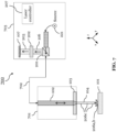
- FIG. 7 shows an apparatus 700 according to an embodiment of the invention, which builds on the apparatus 100 shown in FIG. 1 and has elements in common with the apparatus 200 of FIG. 2 and FIG. 6 .
- Identical elements in FIG. 7 and in FIG. 1 , 2 and/or 6 are labeled with the same reference signs and function likewise.
- the apparatus 700 of FIG. 7 has a different configuration than the apparatus 200 shown in FIG. 6 .
- the apparatus 700 comprises an optical head 701, which includes the machining unit 103.
- the optical head 701 does not comprise the sensing unit 107.
- the sensing unit 107 is provided in a laser unit 703 (including laser source 221 and/or laser controller 207).
- the laser unit 703 may be formed by the laser controller 207 being provided in the laser source 221 or vice versa.
- the laser unit 703 is part of the apparatus 700.
- the machining unit 103 in the optical head 701 is configured to couple the laser beam 102 into the fluid jet 104.
- the sensing unit 107 in the laser unit 703 is configured to receive secondary radiation 206a emitted from a portion of the workpiece 101 that is machined with the laser beam 102.
- the apparatus 700 comprises also an optical connection element 702, particularly an optical fiber 702, optically connecting the optical head 701 and the laser unit 703.
- the laser unit 703 is configured to provide the laser light for the laser beam 102, which is transported through the optical connection element 702 to the optical head 701, e.g. to a supply port of the optical head 701, where it is further provided to the machining unit 103, which couples it into the fluid jet 104.
- Laser-induced electromagnetic radiation 106 is received via the fluid jet 104 by the machining unit 103, and is further provided through the optical head 701 and through the optical connection element 702 to the laser unit 703, e.g. to a supply port of the laser unit 703, where it is further provided towards the sensing unit 107, which converts the secondary radiation 206a, which is included in the laser-induced electromagnetic radiation 106, into the signal 108.
- the laser unit 703 may accordingly comprise also the optical unit 201, which is preferably a beam splitter and is preferably arranged in the optical path between laser source 222 and optical connection element 702, in order to provide the laser light for the laser beam 102 from the laser source 221 to the optical connection element 702. Also the back-propagating laser-induced electromagnetic radiation 106 may pass through this optical unit 201, but is then directed towards the sensing unit 107.
- the laser unit 703 also includes the spectral separation unit 202, which is configured to isolate only electromagnetic radiation of interest 203 including secondary radiation 206a on the sensing unit 107.
- the spectral separation unit 202 is arranged in the optical path between the optical unit 201 and the sensing unit 107, such that it receives the laser-induced electromagnetic radiation 106 including the secondary radiation 206a from the optical unit 201 and provides the radiation of interest 203 onto the sensing unit 107.
- the present invention provides an apparatus 100, 200, 300 and 700, and a method 400, that enable machining a workpiece 101 with a laser beam 102 coupled into a fluid jet 104, wherein due to accurate determination of a state of the machining process, the machining process time can significantly be reduced.
Landscapes
- Physics & Mathematics (AREA)
- Optics & Photonics (AREA)
- Engineering & Computer Science (AREA)
- Plasma & Fusion (AREA)
- Mechanical Engineering (AREA)
- Chemical & Material Sciences (AREA)
- Analytical Chemistry (AREA)
- Laser Beam Processing (AREA)
Description
- The present invention relates to an apparatus for machining a workpiece with a laser beam, and to a corresponding machining method. In particular, the apparatus and method are for machining the workpiece with a laser beam coupled into a fluid jet. The present invention specifically relates to controlling the machining process of the apparatus and the method based on a process emission of secondary radiation.
- A conventional apparatus for machining a workpiece with a laser beam is known. Also a conventional apparatus for machining a workpiece with a laser beam coupled into a fluid jet, wherein the fluid jet impinges onto the workpiece, is generally known.
- A problem typically encountered during the laser beam machining process of a conventional apparatus is that, due to the lack of mechanical interactions of the apparatus with the workpiece, it is difficult to determine characteristic states of the process of machining the workpiece. This difficulty often leads to a significant increase of the machining process time. For example, when a conventional apparatus is used to cut a workpiece with the laser beam, it is problematic to accurately determine, if and when the laser beam has broken through the workpiece material. Thus, the cutting process cannot be finished in a time-optimized manner. Additionally, it would also be beneficial to have the possibility to accurately determine other states of machining the workpiece, for example, states that indicate an instability of the machining process.
- Since the laser beam may be scattered back from the workpiece in an uncontrolled manner, a determination of the process state by visual inspection of the workpiece is difficult or even dangerous. Further, if the conventional apparatus uses a laser beam guided in a fluid jet, additional difficulties arise due to the wet workpiece environment. For instance, since the fluid jet may splatter back from the workpiece in an uncontrolled manner, the fluid may accumulate on surface regions of the workpiece, thereby making it even more difficult to determine states of the machining process.
- Conventional solutions are largely based on visual inspection by means of a camera, for instance, disposed next to the apparatus and/or the workpiece. However, the conventional visual inspection is not very precise, due to the above-mentioned environmental difficulties, especially in wet environments. Further, there is a high risk that the inspection equipment, e.g. the camera, is damaged by splattering fluids. Moreover, the apparatus according to this conventional solution is relatively large, and is inconveniently distributed into multiple separate components.
- In view of these problems and disadvantages, the present invention aims at improving the conventional apparatus and solutions. It is accordingly an object of the present invention to provide an apparatus and a method for machining a workpiece with a laser beam coupled into a fluid jet, which allow reducing the machining process time. In particular, the invention should allow determining more precisely a state of the machining process. The higher the accuracy of determining the state of machining the workpiece is, the better the machining process can be time-optimized. In particular, the invention desires a reliable determination of whether the laser beam has broken through the workpiece material or not. The present invention thereby aims particularly for a compact apparatus and a solution, which is not disturbed by the wet environment caused by the fluid jet. Accordingly, damages to the apparatus and equipment should be avoided.
-
US 2017/0157709 A1 describes an apparatus for determining a spatial position of a liquid jet, in particular a liquid jet for optically guiding a laser beam, through the modification of an orientation. -
WO 2016/194071 A1 discloses a machine tool that performs machining while ejecting a pressurized liquid toward a workpiece. -
US 2015/0209900 A1 describes a method for determining hole completion in laser drilling of an article of manufacture with a laser beam that is directed inside a fluid column. -
US 2016/199941 A1 discloses a method and system for confined laser drilling with a laser beam within a liquid column. -
WO 2012/031009 A1 (forming the basis for the preamble of the independent claims) discloses high power lasers systems, apparatus and methods for performing laser operations, in particular, in environments where an optically obstructive medium is present in the laser beam path, such as within a borehole of an oil, gas, or geothermal well. - The object of the present invention is achieved by the solution provided in the enclosed independent claims. Advantageous implementations of the present invention are defined in the dependent claims.
- In particular, the present invention proposes detecting a state of machining the workpiece based on a process emission, i.e. based on a laser-induced electromagnetic radiation that results from the machining of the workpiece with the laser beam.
- A first aspect of the present invention provides an apparatus for machining a workpiece according to claim 1.
- In the machining unit the laser beam is coupled into the pressurized fluid jet, which acts like a waveguide for the laser beam and guides the laser beam onto the workpiece by means of total internal reflection. The pressurized fluid jet is preferably provided by a fluid nozzle, and the laser beam may be directed by the at least one optical element through the fluid nozzle into the fluid jet and towards the workpiece. The fluid nozzle and the at least one optical element may be separated, for instance by an optical window, in order to prevent contact of the optical element and the fluid.
- The spectral separation unit is arranged and configured to receive the laser-induced electromagnetic radiation propagating away from the workpiece, and separates the electromagnetic radiation of interest from the received radiation, and may provide the radiation of interest including the at least part of said secondary radiation to the sensing unit. The spectral separation unit has the effect that the state of machining the workpiece can be determined even more accurately and more reliably. The spectral separation unit prevents that unwanted radiation reaches the sensing unit. The sensing unit can therefore more sensitively and accurately detect the radiation of interest. The radiation of interest may be the secondary radiation with unwanted other radiation removed, or may be a part of the secondary radiation. It may, for instance, be that the laser beam induces different kinds of electromagnetic radiation caused by different mechanisms. In this case, the radiation of interest may be only secondary radiation caused by one specific mechanism.
- The secondary radiation is specifically caused by the processing of the workpiece with the laser beam, for instance, because the machined surface region of the workpiece is transformed into a plasma. This plasma emits a characteristic radiation, which can be easily isolated on the sensing unit by means of the spectral separation unit, in order to allow a particularly accurate determination of the state of machining the workpiece, especially of whether the laser beam broke through the workpiece.
- The sensing unit may be a photo-detecting device or light sensor, and is configured to detect the secondary radiation included in the laser-induced radiation that travels along the fluid jet in the direction opposite to the primary laser beam, i.e. propagates away from the workpiece. Notably, some electromagnetic radiation induced by the laser beam machining the workpiece may not back-propagate through the fluid jet, but may travel elsewhere.
- The secondary radiation received by the sensing unit provides a very accurate fingerprint of different states of machining the workpiece. In particular, the signal, which is accordingly output by the sensing unit, shows characteristic behaviors depending on the different states of machining the workpiece. Therefore, the signal processing unit is able to accurately and efficiently determine states of machining the workpiece based on the signal. As a consequence, it may trigger according actions of the apparatus based on the determined state, in order to significantly improve the machining process time.
- The fact that the laser-induced electromagnetic radiation is received via the fluid jet allows arranging the sensing unit safe from the wet environment of the machining process. Advantageously, the fluid jet acts as a waveguide also for back-propagating laser-induced radiation, and thus allows a more accurate detection of the secondary radiation included in this laser-induced radiation, and consequently an analysis or post-processing of the signal that the sensing unit supplies when sensing this secondary radiation. Preferably, the sensing unit is housed in the apparatus, more preferably such that it is separated from any fluid circuitry and the fluid nozzle, in order to be protected from fluid contact and thus enjoy an increased lifetime. The apparatus of the first aspect can be built in a very compact manner, and all components of the apparatus may advantageously be integrated.
- Integrating the signal over time improves further the reliability of determining the state of machining the workpiece. In particular, patterns that occur in a single (non-integrated) signal can be enhanced in the integrated signal. Furthermore, additional patterns that appear only in the integrated signal may allow determining further states, or determining the states more precisely. Also the sensitivity of the determination is generally enhanced, since the signal noise impact is reduced.
- In a preferred implementation form of the apparatus, the signal processing unit is configured to determine, as the state of machining the workpiece, whether the laser beam has broken through the workpiece.
- The apparatus of the invention can particularly determine very accurately and quickly, whether the laser beam has broken through the workpiece. Accordingly, the machining process time can be significantly reduced, particularly when the apparatus is used for cutting a workpiece with the laser beam. This is due to the fact that the machining process can be stopped immediately, once the state that the laser beam has broken through the workpiece is determined. The signal processing unit may be configured to automatically provide such an instruction.
- In a further preferred implementation form of the apparatus, the spectral separation unit is arranged to receive the laser-induced electromagnetic radiation propagating through the fluid jet through the at least one optical element, which is configured to couple the laser beam into the fluid jet.
- In this specific way, the apparatus can be built particularly compact. Furthermore, the least amount of optical components are required.
- The apparatus may comprises an optical head including the machining unit and the sensing unit. Accordingly, in the optical head the laser beam can be coupled by the machining unit into the fluid jet, and the sensing unit may sense the secondary radiation included in the laser-induced radiation back-propagating from the workpiece. The signal processing unit may in this case be arranged in the apparatus, e.g. in a housing thereof, but outside the optical head. A laser unit comprising laser source and/or laser controller may be part of the apparatus or not, but is at least separate from the optical head.
- In a further preferred implementation form of the apparatus, the apparatus comprises an optical head including the machining unit, and a laser unit including the spectral separation unit and the sensing unit.
- The laser unit may comprise laser source and/or laser controller. In this implementation form, the laser beam may be provided by the laser unit to the optical head, where it is coupled into the fluid jet by the machining unit. Laser-induced radiation back-propagating from the workpiece may be guided through the optical head to the laser unit, where it is received by the spectral separation unit. The optical head can be optically connected to the laser unit, for instance, by an optical fiber.
- It was surprisingly found that the state of machining the workpiece can be determined precisely by the signal processing unit based on the signal, which is provided by the sensing unit based on the received secondary radiation, even when the sensing unit is arranged in the laser unit, i.e. distanced from the optical head. An advantage of having the spectral separation unit and the sensing unit, and optionally associated optical elements like a beam splitter and/or focusing optics etc., provided in the laser unit is that the handling of these elements, and e.g. their maintenance or replacement, becomes easier. A further advantage is that the optical head can be exchanged without having to exchange the sensing unit and associated optical elements. The optical head can also be built smaller, and the sensing unit and associated optical elements can be built larger, due to more space available in the laser unit.
- In a further preferred implementation form of the apparatus, the apparatus further comprises an optical connection element, particularly an optical fiber, for optically connecting the optical head and the laser unit, wherein the machining unit in the optical head is configured to receive the laser beam via the optical connection element, and the spectral separation unit in the laser unit is configured to receive the laser-induced electromagnetic radiation via the optical connection element.
- Accordingly, the same optical connection element, e.g. optical fiber, is used to transport the laser light for the laser beam and the laser-induced radiation, respectively, within the apparatus, i.e. between the optical head and the laser unit. Nevertheless, the state of machining the workpiece can be accurately determined by the processing unit based on the signal produced accordingly by the sensing unit.
- In a further preferred implementation form of the apparatus, the at least one optical element includes a lens for coupling the laser beam into the fluid jet, and the spectral separation unit is arranged to receive the back-propagating laser-induced electromagnetic radiation through said lens.
- This specific implementation form therefore allows using the lens in a double manner and allows positioning the sensing unit such that it is protected from fluid contact. Further, the apparatus can be built in a compact manner.
- It may be the case that in addition to the secondary radiation emitted from a portion of the workpiece that is machined with the laser beam, also primary laser radiation that is reflected from the workpiece, and/or another secondary radiation generated by scattering of the laser beam in the fluid jet, propagates away from the workpiece through the fluid jet and through the at least one optical element. In this case, the spectral separation unit is used to filter out any unwanted laser-induced electromagnetic radiation, and to focus only the secondary radiation emitted from a portion of the workpiece that is machined with the laser beam, onto the sensing unit.
- In a further preferred implementation form of the apparatus, the signal processing unit is configured to process the signal with a temporal resolution of below 0.5s, preferably of below 0.1s.
- For instance, the temporal resolution of the signal processing unit may be between 0.2-0.5s, or between 0.1-0.5s, or between 0.1-0.2s, or even between 0.01s-0.1s. These preferred temporal resolutions provided by the signal processing unit allow an accurate detection of the state of machining the workpiece, and thus a particularly stable control of the machining process. In particular, the machining process time can be reduced even further with such a signal processing unit.
- In a further preferred implementation form of the apparatus, the apparatus further comprises at least one peripheral device, preferably a laser controller, fluid supply controller, gas supply controller, and/or movement axes controller, wherein the signal processing unit is configured to provide the at least one peripheral device with an instruction signal based on the determined state of machining the workpiece, in order to start, break, stop and/or restart an action of the peripheral device. Accordingly, the machining process time can be optimized. In particular, based on the determined state of machining the workpiece, the apparatus can react quickly to take the necessary actions. For instance, if the laser beam broke through the workpiece, the apparatus can stop the machining process. As a further advantage, the machining process quality can be improved.
- A second aspect of the present invention provides a method of machining a workpiece according to claim 9.
- With the method of the second aspect, the same advantages and effects can be achieved as with the apparatus of the first aspect.
- In a preferred implementation form of the method, the method further comprises, for determining the state of machining the workpiece, recording a plurality of signals, comparing the recorded signals with predetermined reference signals, and determining the state of machining the workpiece based on similar or matching reference signals.
- By providing reference signals and carrying out the comparison with these reference signals, an easy implementation with very accurate results can be provided.
- In a further preferred implementation form of the method, the method comprises determining, as the state of machining the workpiece, that the laser beam has broken through the workpiece, when a value of a single signal or the integrated signal, which increased after a start of machining the workpiece, decreases again below a determined threshold value.
- The above-mentioned characteristic fingerprints in the single signal or integrated signal, i.e. the patterns followed by the signal or integrated signal, have been found to provide very accurate determination results. Moreover, the processing load is low, so that the method can be carried out very quickly.
- The above-described aspects and preferred implementation forms of the present invention are explained in the following description of specific embodiments in relation to the enclosed drawings, in which
-
FIG. 1 shows an apparatus according to an example. -
FIG. 2 shows an apparatus according to an embodiment of the present invention. -
FIG. 3 shows an apparatus according to an embodiment of the present invention. -
FIG. 4 shows a method according to an example. -
FIG. 5 schematically shows characteristic signal patterns used in a method according to an embodiment of the present invention. -
FIG. 6 shows an apparatus according to an embodiment of the present invention. -
FIG. 7 shows an apparatus according to an embodiment of the present invention. -
FIG. 1 shows anapparatus 100 according to an example. In particular, theapparatus 100 is configured to machine aworkpiece 101 with alaser beam 102. Theworkpiece 101 may be a made of a material including, for example, metals, ceramics, diamonds, semiconductors, carbides, alloys, superalloys, or ultra-hard materials. Theworkpiece 101 is notably not a part of theapparatus 100. However, theworkpiece 101 can be positioned on a machining surface, which may or may not be part of theapparatus 100. In either case, theapparatus 100 can be arranged such that it can machine theworkpiece 101 disposed on the machining surface. Theapparatus 100 may also control movements of the machining surface in up to three dimensions. - The
apparatus 100 comprises amachining unit 103, asensing unit 107, and asignal processing unit 109. Theseunits apparatus 100 are preferably all integrated into theapparatus 100, i.e. they are preferably disposed within a housing or enclosure of theapparatus 100. Theapparatus 100 may also comprise further units also disposed within the same housing or enclosure. - The
machining unit 103 is configured to provide apressurized fluid jet 104 onto theworkpiece 101, and to couple thelaser beam 102 into thefluid jet 104. In particular, thelaser beam 102 is coupled into thefluid jet 104 by means of at least oneoptical element 105. This at least oneoptical element 105 may include, for example, one or more lenses, lens assemblies, light guiding optics, beam splitters, mirrors, filters, or polarizers.. Thelaser beam 102 is guided by the preferably thin (i.e. having a diameter in the µm range)fluid jet 104, in principle like it would be guided in an optical fiber. Thelaser beam 102 is apulsed laser beam 102 and is directed towards and onto theworkpiece 101, and can thus be used to precisely machine theworkpiece 101, while thefluid jet 104 continually cools theworkpiece 101 and potentially removes debris. For instance, theapparatus 100 may specifically be configured to accurately cut or shape theworkpiece 101. - The
laser beam 102 is provided by a laser, which may be a part of the apparatus or which may be external but couple thelaser beam 102 into a laser supply port of theapparatus 100. Thelaser beam 102 may be visible, and is preferably from the green spectrum. For instance, thelaser beam 102 may have a wavelength of 532 nm. - The
sensing unit 107 is arranged to receive laser-inducedelectromagnetic radiation 106, i.e. an electromagnetic emission that occurs when theworkpiece 101 is machined with thelaser beam 102. Thus, the laser-inducedelectromagnetic radiation 106 may also be referred to as "process emission". Thesensing unit 107 is arranged such that it can receive, and thus sense, the laser-inducedelectromagnetic radiation 106 propagating away from theworkpiece 101 through thefluid jet 104 and through at least one optical element. Accordingly, the back-propagatingprocess emission 106 can reach thesensing unit 107 guided in and by thefluid jet 104. The at least one optical element, through which thesensing unit 107 can receive theprocess emission 106 can be the at least oneoptical element 105, which is used to couple thelaser beam 102 into thefluid jet 104. This is exemplarily shown inFIG. 1 . - The
sensing unit 107 is further configured to convert the received laser-inducedelectromagnetic radiation 106 into asignal 108, for instance, it provides a photo current as output signal. Thesensing unit 107 may thus, for example, be a photodetector, but it can also be any other device or light sensor that is able to convert at least the electromagnetic radiation of interest into an electrical signal. Thesignal 108 is provided to thesignal processing unit 109 for further analysis and/or processing. - The
signal processing unit 109 is, for example, realized by a microprocessor or computer, and is specifically configured to determine a state of machining theworkpiece 101 based on thesignal 108, which it receives from thesensing unit 107. In particular, thesignal processing unit 109 is configured to determine, as the state of machine theworkpiece 101, whether thelaser beam 102 has broken through theworkpiece 101. In other words, it can determine that and when thelaser beam 102 breaks through theworkpiece 101. To this end, thesignal processing unit 109 may apply signal processing on thesignal 108. Signal processing may include, for example, scaling, averaging, recording over time, integrating over time, or converting thesignal 108, and may include comparing thesignal 108 or an integrated signal with one or more reference signals. For instance, thesignal processing unit 109 may be configured to record a plurality ofsignals 108, and to compare the recordedsignals 108 with pre-stored reference signals. Thesignal processing unit 109 is configured to integrate a plurality ofsignals 108 over time to produce an integrated signal, and to evaluate a pattern or a change of a pattern in the integrated signal. The plurality ofsignals 108 arise from laser-pulse inducedelectromagnetic radiation 106 sensed by thesensing unit 107, as thelaser beam 102 is a pulsed laser beam. - The
signal processing unit 109 may then be configured to determine the state of machining theworkpiece 101 based on similar or matching reference signals (in the first case) or based on the pattern or the change of the pattern (in the second case). Preferably, thesignal processing unit 109 provides a temporal resolution of below 0.5s, preferably of below 0.2s, more preferably of below 0.1s, since preferably thesensing unit 107 is operated with at least 10Hz, more preferably with at least 15 Hz. -
FIG. 2 shows anapparatus 200 according to an embodiment of the present invention, which builds on theapparatus 100 shown inFIG. 1 . Identical elements inFIG. 2 andFIG. 1 are labeled with the same reference signs and function likewise. Accordingly, theapparatus 200 ofFIG. 2 includes themachining unit 103, which is configured to provide thepressurized fluid jet 104 onto theworkpiece 101, and to couple thelaser beam 102 into thefluid jet 104. It also includes thesensing unit 107, which is configured to receive secondary radiation that is included in a back-propagating laser-inducedelectromagnetic radiation 106 via thefluid jet 104 and through themachining unit 103, preferably through the at least oneoptical element 105, and to convert the secondary radiation into thesignal 108. The signal processing unit 109 (here referred to as "Digital signal processing unit + IPC", i.e. thesignal processing unit 109 may also provide inter-process communications (IPC)) is again configured to determine a state of machine theworkpiece 101 based on thesignal 108.FIG. 2 additionally shows further details about the preferred overall layout of theapparatus 200. Theapparatus 200 ofFIG. 2 especially includes several peripheral devices. - The
apparatus 200 may include alaser source 221 and alaser controller 207 for controlling thelaser source 221. Thelaser source 221 is configured to supply 204 the laser light for thelaser beam 102. Thelaser source 221 may also be an external device not included in theapparatus 200 but for supplying 204 the laser light to a laser supply port of theapparatus 200. In theapparatus 200 thelaser beam 102 is preferably directed by anoptical unit 201 of theapparatus 200, which is preferably a beam splitter and preferably arranged in the optical path between themachining unit 103 and thesensing unit 107, towards themachining unit 103. In themachining unit 103, thelaser beam 102 is coupled into thefluid jet 104. Notably, also the back-propagating laser-inducedelectromagnetic radiation 106 passes preferably through thisoptical unit 201, but is directed towards thesensing unit 107. - The
apparatus 200 includes also aspectral separation unit 202, which is configured to isolate only electromagnetic radiation ofinterest 203 including thesecondary radiation 206a on thesensing unit 107. Thespectral separation unit 202 is arranged in the optical path between themachining unit 103 and thesensing unit 107, such that it can receive the laser-inducedelectromagnetic radiation 106 travelling away from theworkpiece 101 through thefluid jet 104 and through the at least oneoptical element 105, and can output the radiation ofinterest 203, which includes at least a part ofsecondary radiation 206a included in the received laser-inducedelectromagnetic radiation 106, onto thesensing unit 107. Thespectral separation unit 202 may be an optical filter unit, which may consist of one or more optical filters and is configured to filter out unwanted electromagnetic radiation, i.e. to prevent electromagnetic radiation of certain (unwanted) wavelengths from reaching thesensing unit 107. The electromagnetic radiation ofinterest 203 may particularly be only the secondary radiation206a, wherein other electromagnetic radiation that accidently reaches the spectral separation unit 202 (and would reach thesensing unit 107 without the spectral separation unit 202) is filtered out. The electromagnetic radiation ofinterest 203 is also be a part of the laser-inducedelectromagnetic radiation 106 that reaches the spectral separation unit 202 (and would reach thesensing unit 107 without the spectral separation unit 202), wherein laser-induced electromagnetic radiation that is not of interest is filtered out. In the embodiment ofFIG. 2 , the laser-induced electromagnetic radiation includes secondary radiation, and thespectral separation unit 202 is configured to prevent laser light reaching thesensing unit 107. That is, thespectral separation unit 202 is configured to filter out light of the same wavelength than provided by thelaser source 221. There are specifically three mechanisms envisaged by this disclosure, which produce laser-inducedelectromagnetic radiation 106 that can provide an accurate fingerprint of the state of machining theworkpiece 101. - In the embodiment of
FIG. 2 , the laser-inducedelectromagnetic radiation 106 includes thesecondary radiation 206a that is emitted from the portion of theworkpiece 101 that is machined with thelaser beam 102. The machined surface portion of theworkpiece 101 may, for instance, be transformed into a plasma by thelaser beam 102, which plasma is the source of thesecondary radiation 206a. Typically, thissecondary radiation 206a is from the yellow and/or orange spectrum. Accordingly, thespectral separation unit 202 may in this case be configured to allow light from the yellow and/or orange spectrum to reach thesensing unit 107, while it blocks light from other parts of the spectrum, especially blocks the laser light e.g. from the green spectrum. Thus, the radiation ofinterest 203 includes only thesecondary radiation 206a. Thesensing unit 107 can in this case be configured to be particularly sensitive to the yellow and/or orange spectrum. - In an example, the laser-induced
electromagnetic radiation 106 could also be or include primary laser radiation 206b reflected from theworkpiece 101, especially from the workpiece surface. Since the laser light is preferably from the green spectrum, thespectral separation unit 202 may in this case be configured to allow light from the green spectrum to reach thesensing unit 107, while it blocks light from other parts of the spectrum. Thus, the radiation ofinterest 203 may include only the secondary radiation 206b. Thesensing unit 107 can in this case be configured to be particularly sensitive to the green spectrum. - In another example, the laser-induced
electromagnetic radiation 106 could also be or includesecondary radiation 206c generated by scattering of thelaser beam 102 in thefluid jet 104. Particularly, thissecondary radiation 206c can be caused by Raman scattering of thelaser beam 102. Typically, thissecondary radiation 206c is from the red spectrum. Accordingly, thespectral separation unit 202 may in this case be configured to allow light from the red spectrum to reach thesensing unit 107, while it blocks light from other parts of the spectrum, especially the laser light e.g. from the green spectrum. Thus, the radiation ofinterest 203 may include only thesecondary radiation 206c. Thesensing unit 107 can in this case be configured to be particularly sensitive to the red spectrum. - Notably, both the
secondary radiation 206a and the laser reflection 206b originate from theworkpiece 101, particularly from the machined workpiece surface portion, while thesecondary radiation 206c originates from thefluid jet 104, particularly from one or several different locations along thefluid jet 104. - The
apparatus 200 can further include several peripheral devices, and thesignal processing unit 109 is preferably configured to provide one or more of the peripheral devices with instruction signals based on the determined state of machining theworkpiece 101. In this manner, thesignal processing unit 109 can control the peripheral devices in dependence of the determined state, and can for example instruct these peripheral devices to start, break, stop and/or restart their respective actions. - For example, the
apparatus 200 shown inFIG. 2 includes as peripheral devices alaser controller 207, a fluid supply controller (here optionally integrated with a fluid pump) 205, a gas supply controller 223 (here a "Protection gas controller", since the gas is preferably used to protectively surround the fluid jet 104), and a movement axes controller 208 (here a "Computer Numerical Control (CNC)"), which may be configured to move in perpendicular X, Y and Z directions and/or rotational a, b, c directions a machining surface, onto which theworkpiece 101 is put, or alternatively theworkpiece 101 itself. - The
signal processing unit 109 is configured to provide respective instruction signals to the different peripheral devices. Preferably, thesignal processing unit 109 can control thelaser controller 207 via asignal 217, thefluid supply controller 205 via asignal 214, thegas supply controller 223 via asignal 216, and the movement axescontroller 208 via asignal 213. Thesignal processing unit 109 preferably controls the peripheral devices independently from another, and without any outside input, but only based on thesignal 108 and the determined state of machining theworkpiece 101. Nevertheless, it is additionally possible that theapparatus 200 includes ahuman machine interface 210, which can receive human/script input 204, in order to provide additional instructions to thesignal processing unit 109 via asignal 212. - According to the instructions provided by the
signal processing unit 109 based on the determined state of machining theworkpiece 101, the peripheral devices can take instructed actions. For instance, thelaser controller 207 may start, pause or stop the supply of laser light for thelaser beam 102. Thefluid supply controller 205 may control a fluidpressure control valve 215, in order to start, break or stop asupply 222 of fluid, which is preferably water, to themachining unit 103. Thegas supply controller 223 can control a protectiongas control valve 211, in order to start, break or stop asupply 219 of gas, which is preferably helium, to themachining unit 103. The movement axescontroller 208 may provide specific movement of theworkpiece 101, i.e. it can control a machining surface, onto which theworkpiece 101 is disposed. -
FIG. 3 shows anapparatus 300 according to an embodiment of the present invention, which builds on theapparatus 100 shown inFIG. 1 and theapparatus 200 shown inFIG. 2 . Identical elements inFIG. 3 and inFIG. 1 and/orFIG. 2 are labeled with the same reference signs and function likewise. In particular,FIG. 3 illustrates more details about the optical arrangement and fluid circuitry of theapparatus 300, particularly as provided in themachining unit 103. Themachining unit 103 may particularly include alens 305 for coupling thelaser beam 102 into thefluid jet 104. Also back-propagating laser-inducedelectromagnetic radiation 106, which includes thesecondary radiation 206a, is preferably transferred through thefluid jet 104 via thislens 305, and then further towards thesensing unit 107. Thereby, theradiation 106 preferably travels from thelens 305 through theoptical unit 201 to thespectral separation unit 202, and further as radiation ofinterest 203 including at least a part of thesecondary radiation 206a to thesensing unit 107. - The
machining unit 103 may also include an opticallytransparent protection window 301, in order to separate the optical arrangement, here exemplarily thelens 305, from the fluid circuitry and the region of themachining unit 103 where thefluid jet 104 is produced. For producing thefluid jet 104, themachining unit 103 preferably includes afluid nozzle 302. Thisfluid nozzle 302 is provided with the fluid via thefluid supply 222, which may be implemented as a channel through the housing or enclosure of theapparatus 300. To this end, thefluid nozzle 302 includes a fluid aperture, which defines the width of thefluid jet 104. The aperture has preferably a diameter of 10-200 µm, and thefluid jet 104 has preferably a diameter of about 0.6-1 times the fluid aperture. The pressure for thepressurized fluid jet 104 is provided via thefluid supply 222. Preferably, the pressure is between 50-800 bar. - It can also be seen in
FIG. 3 that a protection gas, preferably helium, can be supplied viagas supply 219 into themachining unit 103, particularly into a space provided within themachining unit 103, through which the generatedfluid jet 104 passes after leaving thefluid nozzle 302. Here, the protection gas can protectively envelop thefluid jet 104, before thefluid jet 104 exits themachining unit 103 through a lower exit aperture, and then travels further towards and onto theworkpiece 101. - The
apparatus 300 shown inFIG. 3 also includes focusingoptics 300 preferably arranged in the optical path between thespectral separation unit 202 and thesensing unit 107 and for directing light on thesensing unit 107. In particular, the laser-inducedelectromagnetic radiation 106, which back-propagates through thefluid jet 104 through thelens 305, preferably passes theoptical unit 201, then theoptical separation unit 202, and the remaining filtered electromagnetic radiation ofinterest 203 is focused by the focusingoptics 300 onto thesensing unit 107, particularly onto a light-sensitive area of thesensing unit 107. The focusingoptics 300 preferably includes or is at least one lens, but may also include or be another optical element like a parabolic mirror. Thesensing unit 107 is configured to convert the received filtered radiation ofinterest 203 into thesignal 108 for further analysis and/or processing by the signal processing unit 109 (which is not shown here). -
FIG. 3 also shows that the above-described elements of theapparatus 300 may be provided within an enclosure, particularly within anoptical head 303. That is, theapparatus 300 may further comprises theoptical head 303, which may include themachining unit 103 and thesensing unit 107. Theoptical head 303 may also include theoptical unit 201, thespectral separation unit 202, and/or the focusingoptics 300. -
FIG. 4 shows amethod 400 according to an example. Themethod 400 includes astep 401 of providing apressurized fluid jet 104 onto aworkpiece 101 and coupling alaser beam 102 through at least oneoptical element 105 into thefluid jet 104 towards theworkpiece 101. Further, themethod 400 includes astep 402 of receiving a laser-inducedelectromagnetic radiation 106 propagating away from theworkpiece 101 through thefluid jet 104 and through at least one optical element, preferably the at least oneoptical element 105 used for coupling thelaser beam 102 into thefluid jet 104. Further, themethod 400 includes astep 403 of converting the received radiation into asignal 108. Finally, themethod 400 includes astep 404 of determining a state of machining the workpiece based on thesignal 108. - The
method 400 may be carried out by theapparatus FIGs. 1 ,2 and3 , respectively. In particular,step 401 may be carried out by themachining unit 103, thesteps sensing unit 107, and step 404 by thesignal processing unit 109. - The
method 400 particularly includes an automated time-recording ofmultiple signals 108, wherein eachsignal 108 is caused by one of a plurality of laser pulses. That is, thelaser beam 102 is a pulsed laser beam. The laser pulses may be provided regularly and may be in the order of ns. Eachsignal 108 may be represented by a single numeric value or by a sequence of values as a function of time. Multiple obtainedsignals 108 are integrated over time to produce an integrated signal. Themethod 400 may further include an automated comparison of the obtained signals 108 with reference signals, which are read out from a reference storage e.g. from a memory of thesignal processing unit 109. Themethod 400 then includes evaluating a pattern or a change of a pattern in the obtained signals 108 or integrated signal, and determines the state of machining theworkpiece 101 based on said pattern or change of the pattern. Optionally, themethod 400 may include the automated generation of instruction signals or instruction codes and subsequent transmission to one or more peripheral devices, so that these peripheral devices start, break, stop or restart their respective actions. -
FIG. 5 schematically shows twospecific signal patterns signal processing unit 109 of theapparatus workpiece 101. - In particular, the left-hand
side signal pattern 500a is preferably used, if the laser-inducedelectromagnetic radiation 106 is or includes the above-mentionedsecondary radiation 206a emitted from a portion of theworkpiece 101 that is machined with thelaser beam 102. Thesignal pattern 500a indicates that the laser beam has broken through theworkpiece 101, when thesignal 108 or the integrated signal first increases after the "Start" of machining theworkpiece 101 towards an "In-Process" time section, and then decreases again after the "In-Process" time section. When thesignal 108 or integrated signal falls below a determined threshold value, the "Finish" of the process is reached, i.e. it can be determined that the laser beam broke through theworkpiece 101. - Likewise, the right-
hand signal pattern 500b is preferably used, if the laser-inducedelectromagnetic radiation 106 is or includes primary laser radiation 206b reflected from theworkpiece 101. Thesignal pattern 500b indicates that the laser beam has broken through theworkpiece 101, when thesignal 108 or the integrated signal first decreases after the "Start" of machining theworkpiece 101 towards an "In-Process" time section, and then increases again from the "In-Process" time section. When thesignal 108 or integrated signal rises above a determined threshold value, the "Finish" is reached, i.e. the laser beam broke through theworkpiece 101. -
FIG. 6 shows anapparatus 200 according to an embodiment of the present invention, which builds on theapparatus 200 shown inFIG. 2 . Identical elements inFIG. 2 andFIG. 6 are labeled with the same reference signs and function likewise. -
FIG. 6 shows in particular that theapparatus 200 may further include an enclosure, particularly andoptical head 600, which may include themachining unit 103 and thesensing unit 107. Theoptical head 600 also includes thespectral separation unit 202 and may include also theoptical unit 201. As described already with respect toFIG. 2 , the laser light for thelaser beam 102 may be provided 204 by a laser unit 601 (comprisinglaser source 201 and/or laser controller 207), for instance via an optical fiber and to a laser supply port of the apparatus 200 (if thelaser unit 601 is not part of the apparatus 200) or to theoptical head 600, e.g. to a laser supply port of the optical head 600 (if thelaser unit 601 is part of the apparatus 200). -
FIG. 7 shows anapparatus 700 according to an embodiment of the invention, which builds on theapparatus 100 shown inFIG. 1 and has elements in common with theapparatus 200 ofFIG. 2 andFIG. 6 . Identical elements inFIG. 7 and inFIG. 1 ,2 and/or 6 are labeled with the same reference signs and function likewise. - The
apparatus 700 ofFIG. 7 has a different configuration than theapparatus 200 shown inFIG. 6 . In particular, theapparatus 700 comprises anoptical head 701, which includes themachining unit 103. However, theoptical head 701 does not comprise thesensing unit 107. Thesensing unit 107 is provided in a laser unit 703 (includinglaser source 221 and/or laser controller 207). Notably, thelaser unit 703 may be formed by thelaser controller 207 being provided in thelaser source 221 or vice versa. Thelaser unit 703 is part of theapparatus 700. Themachining unit 103 in theoptical head 701 is configured to couple thelaser beam 102 into thefluid jet 104. Thesensing unit 107 in thelaser unit 703 is configured to receivesecondary radiation 206a emitted from a portion of theworkpiece 101 that is machined with thelaser beam 102. - The
apparatus 700 comprises also anoptical connection element 702, particularly anoptical fiber 702, optically connecting theoptical head 701 and thelaser unit 703. Thelaser unit 703 is configured to provide the laser light for thelaser beam 102, which is transported through theoptical connection element 702 to theoptical head 701, e.g. to a supply port of theoptical head 701, where it is further provided to themachining unit 103, which couples it into thefluid jet 104. Laser-inducedelectromagnetic radiation 106 is received via thefluid jet 104 by themachining unit 103, and is further provided through theoptical head 701 and through theoptical connection element 702 to thelaser unit 703, e.g. to a supply port of thelaser unit 703, where it is further provided towards thesensing unit 107, which converts thesecondary radiation 206a, which is included in the laser-inducedelectromagnetic radiation 106, into thesignal 108. - The
laser unit 703 may accordingly comprise also theoptical unit 201, which is preferably a beam splitter and is preferably arranged in the optical path betweenlaser source 222 andoptical connection element 702, in order to provide the laser light for thelaser beam 102 from thelaser source 221 to theoptical connection element 702. Also the back-propagating laser-inducedelectromagnetic radiation 106 may pass through thisoptical unit 201, but is then directed towards thesensing unit 107. Thelaser unit 703 also includes thespectral separation unit 202, which is configured to isolate only electromagnetic radiation ofinterest 203 includingsecondary radiation 206a on thesensing unit 107. Thespectral separation unit 202 is arranged in the optical path between theoptical unit 201 and thesensing unit 107, such that it receives the laser-inducedelectromagnetic radiation 106 including thesecondary radiation 206a from theoptical unit 201 and provides the radiation ofinterest 203 onto thesensing unit 107. - In summary, the present invention provides an
apparatus method 400, that enable machining aworkpiece 101 with alaser beam 102 coupled into afluid jet 104, wherein due to accurate determination of a state of the machining process, the machining process time can significantly be reduced. - The present invention has been described in conjunction with various embodiments as examples as well as implementation forms. However, other variations can be understood and effected by those persons skilled in the art and practicing the claimed invention, from the studies of the drawings, the description and the independent claims. In the claims as well as in the description the word "comprising" does not exclude other elements or steps and the indefinite article "a" or "an" does not exclude a plurality. A single element or other unit may fulfill the functions of several entities or items recited in the claims. The mere fact that certain measures are recited in the mutual different dependent claims does not indicate that a combination of these measures cannot be used in an advantageous implementation.
Claims (11)
- Apparatus (100, 200, 300, 700) for machining a workpiece (101) with a pulsed laser beam (102), the apparatus (100, 200, 300, 700) comprisinga machining unit (103) configured to provide a pressurized fluid jet (104) onto the workpiece (101) and to couple the laser beam (102) through at least one optical element (105) into the fluid jet (104) towards the workpiece (101),a sensing unit (107),a spectral separation unit (202) arranged to receive, during the machining of the workpiece (101) with the laser beam (102), a laser-induced electromagnetic radiation (106) including secondary radiation (206a) emitted from a portion of the workpiece (101) that is machined with the laser beam (102) and propagating away from the workpiece (101) through the fluid jet (104) and through the at least one optical element, and configured to isolate only electromagnetic radiation of interest (203) including at least a part of the secondary radiation (206a) on the sensing unit (107) and to prevent initial laser light (102) to reach the sensing unit (107), characterized by,the sensing unit being configured to convert the secondary radiation (206a) into a signal (108) for each laser pulse, anda signal processing unit (109) configured to integrate a plurality of signals (108) over time to produce an integrated signal, and to determine, during the machining of the workpiece (101) with the laser beam (102), a state of machining the workpiece (101) based on a pattern (500a, 500b) or a change of a pattern (500a, 500b) in the integrated signal (108).
- Apparatus (100, 200, 300, 700) according to claim 1, wherein
the signal processing unit (109) is configured to determine, as the state of machining the workpiece (101), whether the laser beam (102) has broken through the workpiece (101). - Apparatus (100, 200, 300, 700) according to claim 1 or 2, wherein
the spectral separation unit (202) is arranged to receive the laser-induced electromagnetic radiation (106) propagating through the fluid jet (104) through the at least one optical element (105), which is configured to couple the laser beam (102) into the fluid jet (104). - Apparatus (700) according to one of the claims 1 to 3, comprising an optical head (701) including the machining unit (103), and
a laser unit (703) including the spectral separation unit (202) and the sensing unit (107). - Apparatus (700) according to claim 4, further comprisingan optical connection element (702), particularly an optical fiber, for optically connecting the optical head (701) and the laser unit (703), whereinthe machining unit (103) in the optical head (701) is configured to receive the laser beam (102) via the optical connection element (702), andthe spectral separation unit (202) in the laser unit (703) is configured to receive the laser-induced electromagnetic radiation (106) via the optical connection element (702).
- Apparatus (300) according to one of the claims 1 to 5, whereinthe at least one optical element (105) includes a lens (305) for coupling the laser beam (102) into the fluid jet (104), andthe spectral separation unit (202) is arranged to receive the back-propagating laser-induced electromagnetic radiation (106) through said lens (305).
- Apparatus (100, 200, 300, 700) according to one of the claims 1 to 6, wherein
the signal processing unit (109) is configured to process the signal (108) with a temporal resolution of below 0.5s, preferably of below 0.1s. - Apparatus (200, 300, 700) according to one of the claims 1 to 7, further comprisingat least one peripheral device (207, 205, 223, 208), preferably a laser controller (207), fluid supply controller (205), gas supply controller (223), and/or movement axes controller (208),wherein the signal processing unit (109) is configured to provide the at least one peripheral device (207, 205, 223, 208) with an instruction signal (217, 214, 216, 213) based on the determined state of machining the workpiece (101), in order to start, break, stop and/or restart an action of the peripheral device (207, 205, 223, 208).
- Method (400) of machining a workpiece (101) with a pulsed laser beam (102), the method comprisingproviding (401), by a machining unit (103), a pressurized fluid jet (104) onto the workpiece (101) and coupling the laser beam (102) through at least one optical element (105) into the fluid jet (104) towards the workpiece (101),receiving (402), by a spectral separation unit (202) during the machining of the workpiece (101) with the laser beam (102), a laser-induced electromagnetic radiation (106) including secondary radiation emitted from a portion of the workpiece (101) that is machined with the laser beam (102) and propagating away from the workpiece (101) through the fluid jet (104) and through the at least one optical element,isolating, by the spectral separation unit (202), only electromagnetic radiation of interest (203) including at least a part of the secondary radiation (206a) on a sensing unit (107) and preventing initial laser light (102) to reach the sensing unit (107),characterized in that the method comprises:converting (403), by the sensing unit (107), the secondary radiation (206a) into a signal (108) for each laser pulse, anddetermining (404), by a signal processing unit (209) during the machining of the workpiece (101) with the laser beam (102), a state of machining the workpiece (101) based on the signal (108),wherein for determining (404) the state of machining the workpiece (101), the method comprisesintegrating a plurality of signals (108) over time to produce an integrated signal,evaluating a pattern (500a, 500b) or a change of a pattern (500a, 500b) in the integrated signal, anddetermining the state of machining the workpiece (101) based on the pattern (500a, 500b) or the change of the pattern (500a, 500b).
- Method (400) according to claim 9, further comprising, for determining (404) the state of machining the workpiece (101),recording a plurality of signals (108),comparing the recorded signals (108) with predetermined reference signals, anddetermining the state of machining the workpiece (101) based on similar or matching reference signals.
- Method (400) according to claim 9 or 10, comprising
determining (404), as the state of machining the workpiece (101), that the laser beam (102) has broken through the workpiece (101), when a value of a single signal (108) or the integrated signal, which increased after a start of machining the workpiece (101), decreases again below a determined threshold value.
Applications Claiming Priority (2)
| Application Number | Priority Date | Filing Date | Title |
|---|---|---|---|
| EP17195003.3A EP3466597A1 (en) | 2017-10-05 | 2017-10-05 | Apparatus for machining a workpiece with a laser beam |
| PCT/EP2018/077038 WO2019068823A2 (en) | 2017-10-05 | 2018-10-04 | Apparatus for machining a workpiece with a laser beam |
Publications (3)
| Publication Number | Publication Date |
|---|---|
| EP3691828A2 EP3691828A2 (en) | 2020-08-12 |
| EP3691828B1 true EP3691828B1 (en) | 2024-12-04 |
| EP3691828C0 EP3691828C0 (en) | 2024-12-04 |
Family
ID=60022007
Family Applications (2)
| Application Number | Title | Priority Date | Filing Date |
|---|---|---|---|
| EP17195003.3A Withdrawn EP3466597A1 (en) | 2017-10-05 | 2017-10-05 | Apparatus for machining a workpiece with a laser beam |
| EP18780129.5A Active EP3691828B1 (en) | 2017-10-05 | 2018-10-04 | Apparatus and method for machining a workpiece with a laser beam |
Family Applications Before (1)
| Application Number | Title | Priority Date | Filing Date |
|---|---|---|---|
| EP17195003.3A Withdrawn EP3466597A1 (en) | 2017-10-05 | 2017-10-05 | Apparatus for machining a workpiece with a laser beam |
Country Status (9)
| Country | Link |
|---|---|
| US (1) | US11697175B2 (en) |
| EP (2) | EP3466597A1 (en) |
| JP (1) | JP7324515B2 (en) |
| KR (1) | KR102584148B1 (en) |
| CN (1) | CN111194249A (en) |
| CA (1) | CA3074403A1 (en) |
| IL (1) | IL273758B2 (en) |
| RU (1) | RU2764101C2 (en) |
| WO (1) | WO2019068823A2 (en) |
Families Citing this family (4)
| Publication number | Priority date | Publication date | Assignee | Title |
|---|---|---|---|---|
| EP3984687A1 (en) * | 2020-10-16 | 2022-04-20 | Bystronic Laser AG | Beam processing head and beam processing method |
| DE102020213813A1 (en) * | 2020-11-03 | 2022-05-05 | Robert Bosch Gesellschaft mit beschränkter Haftung | Method and device for adjusting operating parameters of a physical system |
| US20240391026A1 (en) * | 2023-05-25 | 2024-11-28 | Industrial Laser Machines, LLC | Liquid Jet Laser Tool Utilizing An Off-Axis Laser Beam |
| AT527326B1 (en) | 2024-02-27 | 2025-01-15 | Aidexa Gmbh | Measuring device for optical scanning using water jet-guided light source irradiation |
Citations (3)
| Publication number | Priority date | Publication date | Assignee | Title |
|---|---|---|---|---|
| WO2012031009A1 (en) * | 2010-08-31 | 2012-03-08 | Foro Energy Inc. | Fluid laser jets, cutting heads, tools and methods of use |
| US20160199941A1 (en) * | 2015-01-08 | 2016-07-14 | General Electric Company | Method and system for confined laser drilling |
| EP3513898A1 (en) * | 2018-01-19 | 2019-07-24 | Synova S.A. | Apparatus for automatic jet angle adjustment |
Family Cites Families (43)
| Publication number | Priority date | Publication date | Assignee | Title |
|---|---|---|---|---|
| JP3147459B2 (en) * | 1992-02-06 | 2001-03-19 | 石川島播磨重工業株式会社 | Processing head of laser beam machine |
| US6163010A (en) * | 1996-10-25 | 2000-12-19 | E. I. Du Pont De Nemours And Company | Method and apparatus for laser cutting materials |
| JPH11254161A (en) | 1998-03-09 | 1999-09-21 | Amada Co Ltd | Laser beam machining device and machining head driving method |
| CN1134322C (en) * | 1998-04-30 | 2004-01-14 | 辛诺瓦有限公司 | Material shaping device with laser beam which is injected into stream of liquid |
| RU2155653C2 (en) * | 1998-06-08 | 2000-09-10 | Курский государственный технический университет | Videosensor apparatus |
| US6140604A (en) * | 1998-06-18 | 2000-10-31 | General Electric Company | Laser drilling breakthrough detector |
| DE19852302A1 (en) * | 1998-11-12 | 2000-05-25 | Fraunhofer Ges Forschung | Method and device for processing workpieces with high-energy radiation |
| DE10103255B4 (en) * | 2001-01-25 | 2004-12-30 | Robert Bosch Gmbh | Procedure for the automatic assessment of laser processing processes |
| FR2836618B1 (en) | 2002-02-28 | 2004-04-16 | Snecma Services | THERMAL PROJECTION INSTRUMENT |
| SE521787C2 (en) * | 2002-04-05 | 2003-12-09 | Volvo Aero Corp | Device and method for controlling a welding area, arrangement and method for controlling a welding operation, computer program and computer program product |
| US7286223B2 (en) * | 2003-03-18 | 2007-10-23 | Loma Linda University Medical Center | Method and apparatus for detecting embedded rebar within an interaction region of a structure irradiated with laser light |
| DE50312360D1 (en) | 2003-08-09 | 2010-03-11 | Trumpf Werkzeugmaschinen Gmbh | Laser processing nozzle coupling |
| JP4537686B2 (en) | 2003-10-27 | 2010-09-01 | 芝浦メカトロニクス株式会社 | Laser processing equipment |
| JP4559260B2 (en) | 2005-03-04 | 2010-10-06 | 日立ビアメカニクス株式会社 | How to drill printed circuit boards |
| JP5035653B2 (en) * | 2005-03-18 | 2012-09-26 | 澁谷工業株式会社 | Hybrid laser processing equipment |
| JP2009000698A (en) | 2007-06-19 | 2009-01-08 | Sumitomo Jukikai Advanced Machinery Kk | Laser processing apparatus and laser processing method |
| US8134098B2 (en) * | 2007-09-28 | 2012-03-13 | Sugino Machine Limited | Laser machining apparatus using laser beam introduced into jet liquid column |
| JP5147445B2 (en) | 2007-09-28 | 2013-02-20 | 株式会社スギノマシン | Laser processing equipment using laser light guided into the jet column |
| JP5196298B2 (en) | 2008-02-18 | 2013-05-15 | 澁谷工業株式会社 | Laser processing equipment |
| JP2009241138A (en) * | 2008-03-31 | 2009-10-22 | Sugino Mach Ltd | Laser beam machining device |
| US20120074110A1 (en) * | 2008-08-20 | 2012-03-29 | Zediker Mark S | Fluid laser jets, cutting heads, tools and methods of use |
| JP5354335B2 (en) | 2008-11-12 | 2013-11-27 | スズキ株式会社 | Laser processing quality determination method and apparatus |
| EP2189236B1 (en) | 2008-11-21 | 2012-06-20 | Synova S.A. | Method and apparatus for improving reliability of a machining process |
| DE112009005060B4 (en) * | 2009-07-10 | 2017-10-19 | Mitsubishi Electric Corp. | Laser processing method and laser processing apparatus |
| JP5431831B2 (en) * | 2009-08-21 | 2014-03-05 | 株式会社ディスコ | Laser processing equipment |
| JP5375476B2 (en) | 2009-09-15 | 2013-12-25 | 新日鐵住金株式会社 | Method for estimating compressive stress value, compressive stress value estimating apparatus, and laser processing apparatus |
| US8525073B2 (en) * | 2010-01-27 | 2013-09-03 | United Technologies Corporation | Depth and breakthrough detection for laser machining |
| JP5482384B2 (en) | 2010-03-31 | 2014-05-07 | 澁谷工業株式会社 | Liquid column observation apparatus and liquid column observation method for laser processing apparatus |
| US10124410B2 (en) * | 2010-09-25 | 2018-11-13 | Ipg Photonics Corporation | Methods and systems for coherent imaging and feedback control for modification of materials |
| ITTO20110352A1 (en) | 2011-04-21 | 2012-10-22 | Adige Spa | METHOD FOR THE CONTROL OF A LASER CUTTING PROCESS AND LASER CUTTING SYSTEM IMPLEMENTING THIS METHOD |
| DE102012003202A1 (en) | 2012-02-17 | 2013-08-22 | Vollmer Werke Maschinenfabrik Gmbh | Device useful for processing workpieces, preferably blades by wet laser, comprises a base, machining unit movably mounted on base, which carries wet laser unit, and workpiece support, where wet laser unit comprises e.g. laser beam source |
| US9468991B2 (en) * | 2014-01-27 | 2016-10-18 | General Electric Company | Method determining hole completion |
| EP2957378A1 (en) * | 2014-06-16 | 2015-12-23 | Synova SA | Machining head for coupling a laser beam and a fluid beam with an interface |
| EP2960006B1 (en) * | 2014-06-23 | 2019-02-20 | Synova S.A. | Method and apparatus for determining a position of a liquid jet through the modification of an orientation |
| WO2016069977A1 (en) * | 2014-10-30 | 2016-05-06 | Schlumberger Canada Limited | Creating radial slots in a subterranean formation |
| US9770785B2 (en) * | 2014-11-18 | 2017-09-26 | General Electric Company | System and method for forming a cooling hole in an airfoil |
| US10589385B2 (en) | 2015-01-08 | 2020-03-17 | General Electric Company | Method and system for confined laser drilling |
| US9776284B2 (en) * | 2015-01-22 | 2017-10-03 | General Electric Company | System and method for cutting a passage in an airfoil |
| US10675710B2 (en) | 2015-05-29 | 2020-06-09 | Makino Milling Machine Co., Ltd. | Machine tool |
| EP3718676B1 (en) | 2015-07-28 | 2023-11-15 | Synova SA | Device and process of treating a workpiece using a liquid jet guided laser beam |
| US10335900B2 (en) | 2016-03-03 | 2019-07-02 | General Electric Company | Protective shield for liquid guided laser cutting tools |
| EP3486027B1 (en) * | 2017-11-21 | 2022-12-28 | Synova S.A. | Measuring a fluid jet guiding a laser beam |
| EP3533557B1 (en) * | 2018-03-01 | 2021-05-26 | Synova S.A. | Apparatus for machining a workpiece with a laser beam coupled into a fluid jet, with automatic laser-nozzle alignment ; method of aligning such a beam |
-
2017
- 2017-10-05 EP EP17195003.3A patent/EP3466597A1/en not_active Withdrawn
-
2018
- 2018-10-04 CN CN201880064929.7A patent/CN111194249A/en active Pending
- 2018-10-04 KR KR1020207009655A patent/KR102584148B1/en active Active
- 2018-10-04 JP JP2020519731A patent/JP7324515B2/en active Active
- 2018-10-04 CA CA3074403A patent/CA3074403A1/en active Pending
- 2018-10-04 US US16/648,697 patent/US11697175B2/en active Active
- 2018-10-04 EP EP18780129.5A patent/EP3691828B1/en active Active
- 2018-10-04 IL IL273758A patent/IL273758B2/en unknown
- 2018-10-04 WO PCT/EP2018/077038 patent/WO2019068823A2/en not_active Ceased
- 2018-10-04 RU RU2020112846A patent/RU2764101C2/en active
Patent Citations (3)
| Publication number | Priority date | Publication date | Assignee | Title |
|---|---|---|---|---|
| WO2012031009A1 (en) * | 2010-08-31 | 2012-03-08 | Foro Energy Inc. | Fluid laser jets, cutting heads, tools and methods of use |
| US20160199941A1 (en) * | 2015-01-08 | 2016-07-14 | General Electric Company | Method and system for confined laser drilling |
| EP3513898A1 (en) * | 2018-01-19 | 2019-07-24 | Synova S.A. | Apparatus for automatic jet angle adjustment |
Also Published As
| Publication number | Publication date |
|---|---|
| JP7324515B2 (en) | 2023-08-10 |
| RU2020112846A3 (en) | 2021-11-09 |
| IL273758B2 (en) | 2025-01-01 |
| CN111194249A (en) | 2020-05-22 |
| WO2019068823A2 (en) | 2019-04-11 |
| KR102584148B1 (en) | 2023-10-04 |
| RU2764101C2 (en) | 2022-01-13 |
| CA3074403A1 (en) | 2019-04-11 |
| US11697175B2 (en) | 2023-07-11 |
| US20200282493A1 (en) | 2020-09-10 |
| IL273758A (en) | 2020-05-31 |
| RU2020112846A (en) | 2021-11-09 |
| KR20200091383A (en) | 2020-07-30 |
| EP3691828C0 (en) | 2024-12-04 |
| WO2019068823A3 (en) | 2019-05-16 |
| EP3466597A1 (en) | 2019-04-10 |
| EP3691828A2 (en) | 2020-08-12 |
| JP2020535974A (en) | 2020-12-10 |
| IL273758B1 (en) | 2024-09-01 |
Similar Documents
| Publication | Publication Date | Title |
|---|---|---|
| US11697175B2 (en) | Apparatus for machining a workpiece with a laser beam | |
| US6720567B2 (en) | Apparatus and method for focal point control for laser machining | |
| US9116131B2 (en) | Method and monitoring device for the detection and monitoring of the contamination of an optical component in a device for laser material processing | |
| EP3486027B1 (en) | Measuring a fluid jet guiding a laser beam | |
| EP2265407B1 (en) | Process monitoring | |
| US7875830B2 (en) | Laser machine monitoring | |
| US20250135576A1 (en) | Method and system for determining the local position of at least one optical element in a machine for laser processing of a material, using low-coherence optical interferometry techniques | |
| US20140014632A1 (en) | Laser processing machine, in particular laser cutting machine, and method for centering a laser beam, in particular a focused laser beam | |
| JP2020535974A5 (en) | ||
| TW202130445A (en) | Method for detecting the operating condition of an optical element arranged along a propagation path of a laser beam of a machine for processing a material, system for carrying out said method and a laser processing machine provided with said system | |
| WO2019054964A2 (en) | Laser cutting system and method providing focusing onto processed material at laser cutting machines | |
| CN111629856B (en) | Device for automatically adjusting jet angle | |
| JP5738051B2 (en) | Laser processing equipment | |
| Braunmüller et al. | Advanced sensors: Industry 4.0 for the laser microjet technology | |
| JP6824092B2 (en) | Laser processing method and laser processing equipment | |
| Gedicke et al. | Comparison of different process monitoring methods for laser beam micro welding | |
| JPH0484683A (en) | Processing head of laser processing equipment |
Legal Events
| Date | Code | Title | Description |
|---|---|---|---|
| STAA | Information on the status of an ep patent application or granted ep patent |
Free format text: STATUS: UNKNOWN |
|
| STAA | Information on the status of an ep patent application or granted ep patent |
Free format text: STATUS: THE INTERNATIONAL PUBLICATION HAS BEEN MADE |
|
| PUAI | Public reference made under article 153(3) epc to a published international application that has entered the european phase |
Free format text: ORIGINAL CODE: 0009012 |
|
| STAA | Information on the status of an ep patent application or granted ep patent |
Free format text: STATUS: REQUEST FOR EXAMINATION WAS MADE |
|
| 17P | Request for examination filed |
Effective date: 20200403 |
|
| AK | Designated contracting states |
Kind code of ref document: A2 Designated state(s): AL AT BE BG CH CY CZ DE DK EE ES FI FR GB GR HR HU IE IS IT LI LT LU LV MC MK MT NL NO PL PT RO RS SE SI SK SM TR |
|
| AX | Request for extension of the european patent |
Extension state: BA ME |
|
| RIN1 | Information on inventor provided before grant (corrected) |
Inventor name: HIPPERT, DAVID Inventor name: RICHERZHAGEN, BERNOLD Inventor name: EPPLE, MAXIMILIAN Inventor name: LAPORTE, GREGOIRE Inventor name: DIEHL, HELGI |
|
| DAV | Request for validation of the european patent (deleted) | ||
| DAX | Request for extension of the european patent (deleted) | ||
| STAA | Information on the status of an ep patent application or granted ep patent |
Free format text: STATUS: EXAMINATION IS IN PROGRESS |
|
| 17Q | First examination report despatched |
Effective date: 20230301 |
|
| GRAP | Despatch of communication of intention to grant a patent |
Free format text: ORIGINAL CODE: EPIDOSNIGR1 |
|
| STAA | Information on the status of an ep patent application or granted ep patent |
Free format text: STATUS: GRANT OF PATENT IS INTENDED |
|
| INTG | Intention to grant announced |
Effective date: 20240523 |
|
| GRAS | Grant fee paid |
Free format text: ORIGINAL CODE: EPIDOSNIGR3 |
|
| GRAJ | Information related to disapproval of communication of intention to grant by the applicant or resumption of examination proceedings by the epo deleted |
Free format text: ORIGINAL CODE: EPIDOSDIGR1 |
|
| GRAL | Information related to payment of fee for publishing/printing deleted |
Free format text: ORIGINAL CODE: EPIDOSDIGR3 |
|
| STAA | Information on the status of an ep patent application or granted ep patent |
Free format text: STATUS: EXAMINATION IS IN PROGRESS |
|
| INTC | Intention to grant announced (deleted) | ||
| GRAP | Despatch of communication of intention to grant a patent |
Free format text: ORIGINAL CODE: EPIDOSNIGR1 |
|
| STAA | Information on the status of an ep patent application or granted ep patent |
Free format text: STATUS: GRANT OF PATENT IS INTENDED |
|
| INTG | Intention to grant announced |
Effective date: 20240906 |
|
| GRAA | (expected) grant |
Free format text: ORIGINAL CODE: 0009210 |
|
| STAA | Information on the status of an ep patent application or granted ep patent |
Free format text: STATUS: THE PATENT HAS BEEN GRANTED |
|
| AK | Designated contracting states |
Kind code of ref document: B1 Designated state(s): AL AT BE BG CH CY CZ DE DK EE ES FI FR GB GR HR HU IE IS IT LI LT LU LV MC MK MT NL NO PL PT RO RS SE SI SK SM TR |
|
| REG | Reference to a national code |
Ref country code: GB Ref legal event code: FG4D |
|
| REG | Reference to a national code |
Ref country code: CH Ref legal event code: EP |
|
| REG | Reference to a national code |
Ref country code: DE Ref legal event code: R096 Ref document number: 602018077245 Country of ref document: DE |
|
| REG | Reference to a national code |
Ref country code: IE Ref legal event code: FG4D |
|
| U01 | Request for unitary effect filed |
Effective date: 20241216 |
|
| U07 | Unitary effect registered |
Designated state(s): AT BE BG DE DK EE FI FR IT LT LU LV MT NL PT RO SE SI Effective date: 20250109 |
|
| PG25 | Lapsed in a contracting state [announced via postgrant information from national office to epo] |
Ref country code: HR Free format text: LAPSE BECAUSE OF FAILURE TO SUBMIT A TRANSLATION OF THE DESCRIPTION OR TO PAY THE FEE WITHIN THE PRESCRIBED TIME-LIMIT Effective date: 20241204 |
|
| PG25 | Lapsed in a contracting state [announced via postgrant information from national office to epo] |
Ref country code: ES Free format text: LAPSE BECAUSE OF FAILURE TO SUBMIT A TRANSLATION OF THE DESCRIPTION OR TO PAY THE FEE WITHIN THE PRESCRIBED TIME-LIMIT Effective date: 20241204 |
|
| PG25 | Lapsed in a contracting state [announced via postgrant information from national office to epo] |
Ref country code: NO Free format text: LAPSE BECAUSE OF FAILURE TO SUBMIT A TRANSLATION OF THE DESCRIPTION OR TO PAY THE FEE WITHIN THE PRESCRIBED TIME-LIMIT Effective date: 20250304 |
|
| PG25 | Lapsed in a contracting state [announced via postgrant information from national office to epo] |
Ref country code: GR Free format text: LAPSE BECAUSE OF FAILURE TO SUBMIT A TRANSLATION OF THE DESCRIPTION OR TO PAY THE FEE WITHIN THE PRESCRIBED TIME-LIMIT Effective date: 20250305 |
|
| PG25 | Lapsed in a contracting state [announced via postgrant information from national office to epo] |
Ref country code: RS Free format text: LAPSE BECAUSE OF FAILURE TO SUBMIT A TRANSLATION OF THE DESCRIPTION OR TO PAY THE FEE WITHIN THE PRESCRIBED TIME-LIMIT Effective date: 20250304 |
|
| PG25 | Lapsed in a contracting state [announced via postgrant information from national office to epo] |
Ref country code: SM Free format text: LAPSE BECAUSE OF FAILURE TO SUBMIT A TRANSLATION OF THE DESCRIPTION OR TO PAY THE FEE WITHIN THE PRESCRIBED TIME-LIMIT Effective date: 20241204 |
|
| PG25 | Lapsed in a contracting state [announced via postgrant information from national office to epo] |
Ref country code: PL Free format text: LAPSE BECAUSE OF FAILURE TO SUBMIT A TRANSLATION OF THE DESCRIPTION OR TO PAY THE FEE WITHIN THE PRESCRIBED TIME-LIMIT Effective date: 20241204 |
|
| PG25 | Lapsed in a contracting state [announced via postgrant information from national office to epo] |
Ref country code: IS Free format text: LAPSE BECAUSE OF FAILURE TO SUBMIT A TRANSLATION OF THE DESCRIPTION OR TO PAY THE FEE WITHIN THE PRESCRIBED TIME-LIMIT Effective date: 20250404 |
|
| PG25 | Lapsed in a contracting state [announced via postgrant information from national office to epo] |
Ref country code: SK Free format text: LAPSE BECAUSE OF FAILURE TO SUBMIT A TRANSLATION OF THE DESCRIPTION OR TO PAY THE FEE WITHIN THE PRESCRIBED TIME-LIMIT Effective date: 20241204 |
|
| PG25 | Lapsed in a contracting state [announced via postgrant information from national office to epo] |
Ref country code: CZ Free format text: LAPSE BECAUSE OF FAILURE TO SUBMIT A TRANSLATION OF THE DESCRIPTION OR TO PAY THE FEE WITHIN THE PRESCRIBED TIME-LIMIT Effective date: 20241204 |
|
| PLBE | No opposition filed within time limit |
Free format text: ORIGINAL CODE: 0009261 |
|
| STAA | Information on the status of an ep patent application or granted ep patent |
Free format text: STATUS: NO OPPOSITION FILED WITHIN TIME LIMIT |
|
| REG | Reference to a national code |
Ref country code: CH Ref legal event code: L10 Free format text: ST27 STATUS EVENT CODE: U-0-0-L10-L00 (AS PROVIDED BY THE NATIONAL OFFICE) Effective date: 20251015 |
|
| REG | Reference to a national code |
Ref country code: CH Ref legal event code: U11 Free format text: ST27 STATUS EVENT CODE: U-0-0-U10-U11 (AS PROVIDED BY THE NATIONAL OFFICE) Effective date: 20251101 |
|
| 26N | No opposition filed |
Effective date: 20250905 |
|
| U20 | Renewal fee for the european patent with unitary effect paid |
Year of fee payment: 8 Effective date: 20251028 |
|
| PGFP | Annual fee paid to national office [announced via postgrant information from national office to epo] |
Ref country code: GB Payment date: 20251022 Year of fee payment: 8 |
|
| PGFP | Annual fee paid to national office [announced via postgrant information from national office to epo] |
Ref country code: CH Payment date: 20251101 Year of fee payment: 8 |