EP3691518B1 - Biometrische vorrichtung zur einnahme und implantation in vivo - Google Patents
Biometrische vorrichtung zur einnahme und implantation in vivo Download PDFInfo
- Publication number
- EP3691518B1 EP3691518B1 EP18792435.2A EP18792435A EP3691518B1 EP 3691518 B1 EP3691518 B1 EP 3691518B1 EP 18792435 A EP18792435 A EP 18792435A EP 3691518 B1 EP3691518 B1 EP 3691518B1
- Authority
- EP
- European Patent Office
- Prior art keywords
- signal
- electrical
- radio antenna
- electrical signal
- fraction
- Prior art date
- Legal status (The legal status is an assumption and is not a legal conclusion. Google has not performed a legal analysis and makes no representation as to the accuracy of the status listed.)
- Active
Links
Images


Classifications
-
- A—HUMAN NECESSITIES
- A61—MEDICAL OR VETERINARY SCIENCE; HYGIENE
- A61B—DIAGNOSIS; SURGERY; IDENTIFICATION
- A61B5/00—Measuring for diagnostic purposes; Identification of persons
- A61B5/0002—Remote monitoring of patients using telemetry, e.g. transmission of vital signals via a communication network
- A61B5/0031—Implanted circuitry
-
- A—HUMAN NECESSITIES
- A61—MEDICAL OR VETERINARY SCIENCE; HYGIENE
- A61B—DIAGNOSIS; SURGERY; IDENTIFICATION
- A61B5/00—Measuring for diagnostic purposes; Identification of persons
- A61B5/05—Detecting, measuring or recording for diagnosis by means of electric currents or magnetic fields; Measuring using microwaves or radio waves
- A61B5/053—Measuring electrical impedance or conductance of a portion of the body
- A61B5/0538—Measuring electrical impedance or conductance of a portion of the body invasively, e.g. using a catheter
-
- A—HUMAN NECESSITIES
- A61—MEDICAL OR VETERINARY SCIENCE; HYGIENE
- A61B—DIAGNOSIS; SURGERY; IDENTIFICATION
- A61B5/00—Measuring for diagnostic purposes; Identification of persons
- A61B5/05—Detecting, measuring or recording for diagnosis by means of electric currents or magnetic fields; Measuring using microwaves or radio waves
- A61B5/0507—Detecting, measuring or recording for diagnosis by means of electric currents or magnetic fields; Measuring using microwaves or radio waves using microwaves or terahertz waves
-
- A—HUMAN NECESSITIES
- A61—MEDICAL OR VETERINARY SCIENCE; HYGIENE
- A61B—DIAGNOSIS; SURGERY; IDENTIFICATION
- A61B5/00—Measuring for diagnostic purposes; Identification of persons
- A61B5/05—Detecting, measuring or recording for diagnosis by means of electric currents or magnetic fields; Measuring using microwaves or radio waves
- A61B5/053—Measuring electrical impedance or conductance of a portion of the body
- A61B5/0537—Measuring body composition by impedance, e.g. tissue hydration or fat content
-
- A—HUMAN NECESSITIES
- A61—MEDICAL OR VETERINARY SCIENCE; HYGIENE
- A61B—DIAGNOSIS; SURGERY; IDENTIFICATION
- A61B5/00—Measuring for diagnostic purposes; Identification of persons
- A61B5/07—Endoradiosondes
-
- A—HUMAN NECESSITIES
- A61—MEDICAL OR VETERINARY SCIENCE; HYGIENE
- A61B—DIAGNOSIS; SURGERY; IDENTIFICATION
- A61B5/00—Measuring for diagnostic purposes; Identification of persons
- A61B5/07—Endoradiosondes
- A61B5/073—Intestinal transmitters
-
- A—HUMAN NECESSITIES
- A61—MEDICAL OR VETERINARY SCIENCE; HYGIENE
- A61B—DIAGNOSIS; SURGERY; IDENTIFICATION
- A61B1/00—Instruments for performing medical examinations of the interior of cavities or tubes of the body by visual or photographical inspection, e.g. endoscopes; Illuminating arrangements therefor
- A61B1/04—Instruments for performing medical examinations of the interior of cavities or tubes of the body by visual or photographical inspection, e.g. endoscopes; Illuminating arrangements therefor combined with photographic or television appliances
- A61B1/041—Capsule endoscopes for imaging
-
- A—HUMAN NECESSITIES
- A61—MEDICAL OR VETERINARY SCIENCE; HYGIENE
- A61B—DIAGNOSIS; SURGERY; IDENTIFICATION
- A61B5/00—Measuring for diagnostic purposes; Identification of persons
- A61B5/72—Signal processing specially adapted for physiological signals or for diagnostic purposes
- A61B5/7225—Details of analogue processing, e.g. isolation amplifier, gain or sensitivity adjustment, filtering, baseline or drift compensation
Definitions
- the present description relates to a biotelemetric device for use in an in vivo environment and an associated method.
- biotelemetric devices are used for the acquisition of physiological signals and the analysis of associated physiological data.
- biotelemetric devices there are ingestible and/or implantable wireless biotelemetric devices, which can be used both for the collection and transmission of physiological signals and the implementation of therapeutic functions, such as for example the delivery of drugs or electrical stimulation.
- biotelemetric devices are for example in the form of ingestible capsules or implants that can be inserted into the body of humans or animals.
- biotelemetric devices integrate at least one radio antenna to transmit data to external data control/analysis equipment or receive commands from such equipment.
- These external equipments are used in particular to analyze ex vivo the data transmitted by the radio antenna.
- US 2017/95,667 describes for example a device whose implantable part is equipped with a radiofrequency antenna for communication with the external device, impedance-matched so that communication is as efficient as possible when the device is implanted.
- the biotelemetric device is said to be external to the human or animal body.
- biotelemetric devices can integrate one or more miniaturized sensors or transducers for measuring physiological variables from the surrounding environment, for example a sensor capable of measuring pH, temperature or pressure in the entire gastrointestinal tract.
- pH detection sensors made in the form of glass electrodes, are bulky, expensive and consume energy.
- biotelemetric devices intended for use in an in vivo environment involve constraints regarding the choice, arrangement and number of usable electronic components.
- the present description relates, according to a first aspect, to a biotelemetric device that can be integrated into a biocompatible capsule and intended to be used in a biological environment after ingestion or implantation in vivo, in association with external equipment.
- This device comprises: a microcontroller configured to generate an electrical setpoint signal; a radio antenna configured to emit at least one electromagnetic wave by converting an incident electrical signal, so as to transmit data to said external equipment via a radio link with said external equipment; a radio frequency circuit, interconnected between the microcontroller and the radio antenna.
- the radio antenna is configured to, when the biotelemetric device is placed in the biological environment, be impedance-mismatched with respect to the radio frequency circuit so as to generate a reflected electrical signal by reflecting a fraction of the incident electrical signal at the same time as the radio antenna emits the at least one electromagnetic wave detectable by said external equipment.
- the radiofrequency circuit is configured to take a first fraction of the reference electrical signal, transmit to the radio antenna a second fraction of the reference electrical signal forming the incident electrical signal and take the electrical signal reflected by the radio antenna.
- the microcontroller is configured to determine, relative to the first fraction of the set electrical signal, a reflection coefficient corresponding to the fraction of the electrical signal reflected by the radio antenna.
- the radio antenna is used concomitantly for the emission of electromagnetic waves, detectable for example by external equipment, and for producing a reflected electrical signal resulting from an impedance mismatch of the radio antenna with respect to the radio frequency circuit.
- the electrical signal reflected by The radio antenna is representative of the electromagnetic properties (in particular permittivity, conductivity) of the surrounding environment.
- the reflection coefficient can therefore be used to characterize the electromagnetic properties of this surrounding environment.
- Such a biotelemetric device thus makes it possible, from the reflection coefficient, to detect and quantify the variations in the electromagnetic properties (in particular permittivity, conductivity) of biological tissues and to deduce the physiological changes in correlation with the variation in the electromagnetic properties.
- the calculation of the reflection coefficient, as well as the determination of the electromagnetic properties on the basis of the reflection coefficient, can be carried out by the microcontroller or by the external equipment communicating with the microcontroller by means of the electromagnetic waves emitted by the radio antenna.
- the combination of this method of detecting the electromagnetic properties of biological tissues with an additional sensor makes it possible to determine physiological parameters, such as pH, glucose level, lactate level, cholesterol level, and this, without requiring a sensor specific to each of these physiological parameters.
- physiological parameters such as pH, glucose level, lactate level, cholesterol level, and this.
- the biotelemetric device can be used to produce a non-invasive and autonomous glucose sensor, capable of automatically alerting the patient or his doctor in the event of an abnormal glucose level.
- the biotelemetric device described in this document is more energy efficient and less expensive than devices with dedicated biomedical sensors or application circuits.
- the biotelemetric device allows in vivo measurement of the EM properties of an organ of the human or animal body, which has not been achieved to date.
- the microcontroller is further configured to obtain a first comparison electrical signal resulting from a comparison between a reference signal and the first fraction taken from the signal of the setpoint electrical signal and to obtain a second electrical comparison signal resulting from a comparison between the reference signal and the electrical signal reflected by the radio antenna.
- the microcontroller is further configured to determine the reflection coefficient from the first comparison electrical signal and the second comparison electrical signal.
- the microcontroller is further configured to determine an electromagnetic parameter of the biological environment from the amplitude and phase of the first comparison electrical signal and the amplitude and phase of the second comparison electrical signal.
- the radiofrequency circuit comprises a power divider configured to take the first fraction of the setpoint electrical signal and generate the incident electrical signal.
- the radio frequency circuit comprises a directional coupler configured to pick up the electrical signal reflected by the radio antenna.
- the radiofrequency circuit comprises a reference receiver configured to compare the reference signal and the first fraction taken from the signal of the setpoint electrical signal and a test receiver configured to compare the reference signal and the electrical signal reflected by the radioelectric antenna.
- the radiofrequency circuit further comprises at least one switch configured to switch the radiofrequency circuit from a first operating mode to a second operating mode and vice versa, the radiofrequency circuit being configured to, in the first operating mode, take the first fraction of the setpoint electrical signal and the fraction of the electrical signal reflected by the radio antenna and to generate the incident electrical signal from the second fraction of the setpoint electrical signal; the radiofrequency circuit being configured to, in the second operating mode, transmit the entire setpoint electrical signal to the radio antenna and not take any fraction of the electrical signal reflected by the radio antenna.
- the biotelemetric device comprises an impedance matching circuit, interconnected between the microcontroller and the radiofrequency circuit and configured to implement a parameterized impedance matching based on the determined reflection coefficient.
- the reflection coefficient is, at the operating frequency of the radio antenna, less than -3dB.
- the microcontroller is further configured to determine from the reflection coefficient a complex impedance of the antenna in the biological medium at the operating frequency of the radio antenna.
- the microcontroller is further configured to determine one or more electromagnetic properties of the biological medium from a model relating the complex impedance of the antenna in free space to the complex impedance of the antenna in the biological medium and the one or more electromagnetic properties.
- the invention relates to a system comprising a biotelemetric device and an external device configured to receive electromagnetic waves emitted by the antenna of the biotelemetric device and/or to transmit commands to the biotelemetric device.
- the external device is further configured to determine from the reflection coefficient a complex impedance of the antenna in the biological medium at the operating frequency of the radio antenna and to determine one or more electromagnetic properties of the biological medium from a model relating the complex impedance of the antenna in free space to the complex impedance of the antenna in the biological medium and the one or more electromagnetic properties.
- the present description also relates, according to a second aspect, to a biotelemetric measurement method, the method being intended to be implemented by means of a biotelemetric device that can be integrated into a biocompatible capsule and intended to be used in a surrounding biological environment after ingestion or in vivo implantation, emitting at least one electromagnetic wave detectable by external equipment, the method comprising a generation of an electrical setpoint signal by a microcontroller of the biotelemetric device; an emission, by a radio antenna of the device biotelemetric, of at least one electromagnetic wave, detectable by said external equipment, by conversion of the incident electrical signal, so as to transmit data to said external equipment via a radio link with said external equipment; a generation of a reflected electrical signal, the reflected electrical signal resulting from an impedance mismatch of the radio antenna with respect to the radiofrequency circuit when the biotelemetric device is placed in the biological environment and being generated by reflection by the radio antenna of a fraction of the incident electrical signal concomitantly with the emission of the electromagnetic wave; a sampling, by a radiofrequency
- the method according to the second aspect is implemented by the biotelemetric device according to the first aspect.
- the biotelemetric device according to the first aspect comprises means for implementing the method according to the second aspect and, conversely, the method according to the second aspect comprises steps corresponding to the functions implemented by the biotelemetric device according to the first aspect.
- the characteristics, properties, advantages and/or effects of the biotelemetric device according to the first aspect are directly transposable to the method according to the second aspect and vice versa.
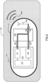
- FIG. 1 schematically represents an example of a biotelemetric device 100, in the form of an ingestible capsule.
- the biotelemetric device 100 comprises a microcontroller 101, a radiofrequency circuit 102, a wireless communication unit 103, a power source 104.
- the biotelemetric device 100 may comprise an additional circuit 105, for example a biomedical application circuit or a sensor.
- the biotelemetric device 100 may be implemented using one or more integrated circuits, each integrating one or more of the components of the biotelemetric device 100.
- the power source 104 is configured to electrically power the microcontroller 101, the radio frequency circuit 102, the wireless communication unit 103 and the additional circuit 105.
- the wireless communication unit 103 is configured to communicate via a radio link with an external device (not shown).
- the wireless communication unit 103 may for example transmit data (e.g. biotelemetry data acquired by the biotelemetry device 100) to the external device and receive data (e.g. operational and/or therapeutic treatment instructions) from such an external device.
- the wireless communication unit 103 is embodied as a radio antenna capable of transmitting and receiving high frequency electromagnetic waves, for example in the range of 10 7 Hz to 10 10 Hz.
- the antenna may be made of an electrically conductive material (e.g., a metal such as copper, aluminum, silver, or an alloy, etc.).
- the antenna may be printed on a substrate made of a dielectric material.
- the wireless communication unit 103 is made as an inductive coil for transmitting and receiving data by a near-field technique.
- the microcontroller 101 is configured to process data, for example to process data received by the wireless communication unit 103 or data acquired by the additional circuit 105.
- the capsule can be made, for example, of biocompatible plastic material (PVC, PTFE, PEEK, Polyethylene, etc.), polymer or ceramic.
- the radio frequency circuit 102 is interconnected between the microcontroller 101 and the radio antenna 103.
- the radio frequency circuit 102 serves as an electrical interface between the microcontroller 101.
- the biomedical application circuit 105 is configured to implement diagnostic functions and/or therapeutic functions.
- the diagnostic functions may include functions for acquiring or measuring diagnostic data, for example by means of one or more sensors, such as for example, temperature sensors, electronic sensors, MEMS ("Microelectromechanical systems") or microfluidic sensors.
- the diagnostic functions may include functions for endoscopy, image acquisition, measurement of glucose or other physiological parameters, detection of antibodies, etc.
- the therapeutic functions may include for example the delivery of drugs and electrical stimulation, for example nerve stimulation.
- the biotelemetric device 100 is intended to be used in a surrounding biological environment 110, for example after ingestion or in vivo implantation. As the biotelemetric device 100 moves through the human body, for example during gastrointestinal transit, this biological environment 110 is likely to have varied properties.
- the electromagnetic (EM) properties of the biological medium 110 surrounding the biotelemetric device 100 determine the coupling between the radio antenna 103 and the biological medium 110 and the absorption of EM fields by this biological medium 110. knowledge of these EM properties makes it possible to adapt the configuration of the radio antenna 103 to optimize the wireless transmission performance of the radio antenna 103 through the biological medium.
- the coupling between the radio antenna 103 and the biological medium 110 is important, and the transmission properties of the radio antenna are affected by variations in the EM properties of the biological medium 110 in which the biotelemetric device 100 is located. This variation in the EM properties of the biological medium 110 can therefore be detected and, if necessary, quantified.
- FIG. 2 illustrates in more detail the operating principle of the biotelemetric device 100.
- the microcontroller 101 is configured to generate an electrical setpoint signal CS to be converted into an electromagnetic wave EMS by the radio antenna 103.
- the radio antenna 103 is configured to emit an electromagnetic wave EMS by converting an incident electrical signal IS.
- the incident electrical signal IS is generated by the radio frequency circuit 102 from the set electrical signal CS.
- the radio antenna 103 is configured to, when the biotelemetric device 100 is placed in the biological environment 110, be impedance-mismatched relative to the radiofrequency circuit 102 so as to generate a reflected electrical signal RS by reflection of a fraction of the incident electrical signal IS, at the same time as the radio antenna 103 emits an electromagnetic wave EMS.
- the electrical signal RS reflected by the radio antenna 103 is a function of the impedance mismatch rate between the radio antenna 103 and the radio frequency circuit.
- the impedance of the radio antenna 103 strongly depends on the EM properties of the biological medium 110 with which the radio antenna 103 is coupled.
- the electrical signal RS reflected by the radio antenna 103 is a function of the EM properties of this biological medium 110.
- Z ANT ⁇ ⁇ ⁇ R + jX
- the radio antenna 103 can be used both for the emission of an electromagnetic wave EMS and for deducing the EM properties of the biological medium 110 from the electrical signal RS reflected by the radio antenna.
- the impedance mismatch rate between the radio antenna and the radio frequency circuit can be evaluated on the basis of the reflection coefficient S 11 .
- This reflection coefficient S 11 can be determined at the operating frequency of the radio antenna as a function of the incident electrical signal IS and the reflected electrical signal RS.
- This reflection coefficient S 11 is a function of the EM properties (in particular, permittivity and conductivity) of the biological medium 110 with which the radio antenna 103 is coupled.
- the reflection coefficient S 11 is determined as the complex ratio (i.e. amplitude and phase) between the complex intensity of the incident electrical signal IS and the complex intensity of the reflected electrical signal RS: .
- S 11 E RS E IS
- E represents the complex intensity of an electric field or signal.
- the impedance mismatch rate between the radio antenna 103 and the radio frequency 101 is limited so as to guarantee an acceptable level of performance of the radio antenna 103 in data transmission at the operating frequency f 0 .
- the configuration of the radio antenna will be chosen so that the reflection coefficient
- the operating frequency f 0 of the radio antenna 103 corresponds to the frequency of the electromagnetic wave emitted by the radio antenna.
- the microcontroller comprises an electrical signal analysis unit 111 configured to calculate the complex impedance Z ANT of the radio antenna 103, the reflection coefficient S 11 and/or values of electromagnetic or physiological properties of the surrounding biological environment 110 from the reflected electrical signal RS.
- the microcontroller 101 comprises an electrical signal generation unit 112 configured to generate the electrical setpoint signal CS.
- the microcontroller comprises a data processing unit 113.
- the data processing unit 113 is for example configured to, from the parameter values (complex impedance Z ANT of the radio antenna 103, reflection coefficient S 11 , electromagnetic properties and/or physiological properties of the biological medium 110) calculated by the signal analysis unit 111 electrical, determine the setpoint signal CS to be emitted by the electrical signal generation unit 112.
- the microcontroller 101 (or the external device) is configured to determine the complex impedance Z ANT of the radio antenna 103 at the operating frequency determined from the reflection coefficient S 11 and/or the complex intensity of the incident electrical signal IS and the reflected electrical signal RS on the basis of equations (eq3) and (eq4).
- the microcontroller 101 (or the external device) is configured to determine EM properties (in particular, permittivity ⁇ and conductivity ⁇ ) of the surrounding biological medium from the complex impedance Z ANT and/or the reflection coefficient S 11 .
- EM properties in particular, permittivity ⁇ and conductivity ⁇
- Such a determination depends on the physical configuration of the radio antenna and can be performed from a mathematical model linking the complex impedance in free space to the complex impedance in vivo and to the EM properties (in particular, permittivity ⁇ and conductivity ⁇ ).
- Such a determination can be performed in particular on the basis of equation (eq2).
- a numerical model can be generated by using the radio antenna in media with known EM properties, such as to relate, for example, values of the complex impedance Z ANT of the radio antenna in the medium and/or of the reflection coefficient S 11 to values of permittivity ⁇ and/or conductivity ⁇ of the medium. Then the radio antenna can be used in media with unknown EM properties, the values of these properties being determined by interpolation from the values of the numerical model, and from the complex impedance Z ANT and/or the reflection coefficient S 11 determined by the microcontroller.
- the impedance variation caused by the surrounding biological medium 110 depends on the thickness and permittivity of the biocompatible capsule in which the biotelemetric device is encapsulated and which separates the biotelemetric device from the biological medium 110.
- the radio antenna is configured to operate in biological environments having varied EM properties.
- the radio antenna is for example made of a microstrip, and isolated from the biological environment by a biocompatible capsule with high permittivity in which this radio antenna is encapsulated.
- the antenna can also be made of an electrically conductive material (for example, of a metal such as copper, aluminum, silver, etc. or an alloy).
- an electrically conductive material for example, of a metal such as copper, aluminum, silver, etc. or an alloy.
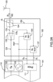
- FIG. 3A shows a first example of implementation of the radiofrequency circuit 102 and the microcontroller 101.
- the electrical signal generation unit 112 comprises a sub-unit 132 for generating the setpoint electrical signal CS and a sub-unit 133 for generating a reference electrical signal REF.
- the reference signal is for example a harmonic signal.
- the radiofrequency circuit 102 comprises a power divider 123 configured to take a first fraction CS1 of the setpoint electrical signal, take a second fraction CS2 of the setpoint electrical signal and generate the incident electrical signal IS from the first fraction CS1 of the setpoint electrical signal.
- the incident electrical signal IS corresponds to the first fraction CS1 of the setpoint electrical signal.
- the radiofrequency circuit 102 comprises an analyzer configured to compare the amplitude and/or the phase of the second fraction CS2 of the electrical reference signal with those of the reference signal REF.
- this analyzer comprises a directional coupler 124, a test receiver 121 and a reference receiver 122.
- the directional coupler 124 configured to pick up the electrical signal RS reflected by the radio antenna 103.
- the test receiver 121 is configured to compare the reflected electrical signal RS collected by the directional coupler 124 with the reference signal REF.
- the first test receiver 121 generates a comparison electrical signal S1 resulting from this comparison.
- the comparison carried out by the test receiver consists in comparing the amplitude and the phase of the reflected electrical signal RS collected by the directional coupler 124 with those of the reference signal REF.
- the reference receiver 122 is configured to compare the second fraction CS2 of the electrical reference signal with the reference signal REF.
- the test receiver 121 generates a comparison electrical signal S2 resulting from this comparison.
- the comparison carried out by the second network receiver consists in comparing the amplitude and the phase of the second fraction CS2 of the electrical reference signal with those of the reference signal REF.
- the radiofrequency circuit 102 is configured to take a first fraction CS1 of the setpoint electrical signal CS, transmit to the radio antenna a second fraction CS2 of the setpoint electrical signal forming the incident electrical signal IS and take the electrical signal reflected RS by the radio antenna, by separating the reflected electrical signal RS from the incident electrical signal IS.
- the microcontroller is configured to determine, relative to the first fraction CS1 of the setpoint electrical signal, the reflection coefficient S11 corresponding to the fraction of the electrical signal reflected RS by the radio antenna 103.
- the electrical signal analysis unit 111 is configured to receive the comparison electrical signals S1 and S2 and to calculate the complex impedance ZANT of the radio antenna 103, the reflection coefficient S11 and/or values of electromagnetic or physiological properties of the surrounding biological environment 110 from the comparison electrical signals S1 and S2.
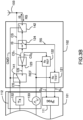
- FIG. 3B shows a second example of implementation of the radiofrequency circuit 102 and the microcontroller 101.
- the elements identical to those of the first example of implementation of the radiofrequency circuit described with reference to the FIG. 3A are not described again and bear the same references in the Figures 3A And 3B .
- the radiofrequency circuit 102 further comprises at least one electrical switch 141, 142 configured to switch the radiofrequency circuit 102 from a first operating mode to a second operating mode and vice versa.
- the radiofrequency circuit 102 is configured to, in the first operating mode, to take the first fraction of the setpoint electrical signal and the fraction of the electrical signal reflected by the radioelectric antenna and to generating the incident electrical signal from the second fraction of the setpoint electrical signal.
- the radiofrequency circuit is configured to, in the second operating mode, transmit the entire setpoint electrical signal to the radio antenna and not take any fraction of the electrical signal reflected by the radio antenna.
- a first electrical switch 141 is interconnected between the output of the sub-unit 132 for generating the electrical setpoint signal CS and the input of the power divider 123 and a second electrical switch 141 is interconnected between the output of the directional coupler 124 and the radio antenna 103.
- the biotelemetric device comprises an impedance matching circuit 150 (not shown), interconnected between the radio antenna 103 and the radiofrequency circuit 102.
- the impedance matching circuit 150 is configured to implement an impedance matching. This impedance matching is for example parameterized according to the reflection coefficient S 11 .
- the reflection coefficient S 11 actually obtained and the properties (in particular amplitude, phase) of the reflected electrical signal RS for example according to the intended use for the biotelemetric device 100 at a given time or so as to obtain a given quality level for the reflected electrical signal RS or the electromagnetic wave EMS emitted by the antenna or to increase the range of the antenna.
- FIG. 4A shows the variation curves of the relative permittivity of different organs as a function of the operating frequency: stomach, small intestine, colon and muscle.
- the values for the esophagus are identical to those for the stomach. It is observed that, for a given operating frequency, the relative permittivity depends on the organ, the differences remaining significant below 1 GHz.
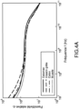
- FIG. 4B shows the conductivity variation curves of different organs as a function of operating frequency: stomach, small intestine, colon and muscle.
- the values for the esophagus are identical to those for the stomach. It is also observed that, for a given operating frequency, the relative permittivity depends on the organ, with the differences remaining significant below 10 GHz.
- the biotelemetric device it is possible to determine, for example in the microcontroller or in an external device communicating with the biotelemetric device 100, on the basis of variation curves of the EM properties in different organs such as those of the Figures 4A And 4B , the organ of the human body in which the biotelemetric device is located at a given time depending on the EM properties of the biological medium 110 determined by the microcontroller 101 from the complex impedance Z ANT and/or the reflection coefficient S 11 .
- Other information can then be deduced, such as for example a gastrointestinal transit time.
- the biotelemetric device is configured to perform an endoscopy of a specific organ or a specific section of the gastrointestinal tract (e.g., the small intestine)
- a specific organ or a specific section of the gastrointestinal tract e.g., the small intestine
- the biotelemetric device is configured to deliver a drug to a specific organ or a specific section of the gastrointestinal tract
- the drug may be released automatically when the EM properties of the biological medium 110 match the EM properties of that specific organ or that specific section respectively.
- the table of the FIG. 5 gives some example values of relative permittivity and conductivity for the stomach, small intestine, colon and muscle at some example operating frequency values. It is observed that beyond 2.4GHz, the values for the small intestine and colon are very close: it is therefore difficult to distinguish these two organs when working at such frequencies.
- the biotelemetric device has many application possibilities in both medical and non-medical fields, for example, civil engineering, agriculture, food processing, etc.
Landscapes
- Health & Medical Sciences (AREA)
- Life Sciences & Earth Sciences (AREA)
- Engineering & Computer Science (AREA)
- Surgery (AREA)
- General Health & Medical Sciences (AREA)
- Biophysics (AREA)
- Biomedical Technology (AREA)
- Heart & Thoracic Surgery (AREA)
- Medical Informatics (AREA)
- Molecular Biology (AREA)
- Physics & Mathematics (AREA)
- Animal Behavior & Ethology (AREA)
- Pathology (AREA)
- Public Health (AREA)
- Veterinary Medicine (AREA)
- Nuclear Medicine, Radiotherapy & Molecular Imaging (AREA)
- Radiology & Medical Imaging (AREA)
- Computer Networks & Wireless Communication (AREA)
- Measuring And Recording Apparatus For Diagnosis (AREA)
- Measurement Of The Respiration, Hearing Ability, Form, And Blood Characteristics Of Living Organisms (AREA)
- Electrotherapy Devices (AREA)
- Endoscopes (AREA)
Claims (15)
- Biotelemetrische Vorrichtung (100), die in eine biokompatible Kapsel integriert werden kann und zur Verwendung in einem biologischen Medium (110) nach Einnahme oder Implantation in vivo in Assoziation mit einer externen Ausrüstung bestimmt ist, wobei die biotelemetrische Vorrichtung (100) Folgendes umfasst:- einen Mikrocontroller (101), der zum Erzeugen eines elektrischen Sollwertsignals (CS) konfiguriert ist;- eine Funkantenne (103), die zum Aussenden mindestens einer elektromagnetischen Welle (EMS) durch Umwandeln eines einfallenden elektrischen Signals (IS) konfiguriert ist, um Daten zu der genannten externen Ausrüstung über eine Funkverbindung mit der genannten externen Ausrüstung zu übertragen;- eine Hochfrequenzschaltung (102), die zwischen den Mikrocontroller (101) und die Funkantenne (103) geschaltet ist,wobei die Funkantenne (103) so konfiguriert ist, dass sie, wenn die biotelemetrische Vorrichtung (100) in dem biologischen Medium (110) platziert ist, in Bezug auf die Hochfrequenzschaltung (102) impedanzfehlangepasst wird, um ein reflektiertes elektrisches Signal (RS) durch Reflexion eines Teils des einfallenden elektrischen Signals zu erzeugen, während gleichzeitig die Funkantenne die mindestens eine elektromagnetische Welle (EMS) aussendet, die durch die genannte externe Ausrüstung erfassbar ist;wobei die Hochfrequenzschaltung (102) konfiguriert ist zum Abgreifen eines ersten Teils (CS2) des elektrischen Sollwertsignals, Übertragen eines zweiten Teils (CS1) des elektrischen Sollwertsignals, der das einfallende elektrische Signal (IS) bildet, zu der Funkantenne und Abgreifen des von der Funkantenne (103) reflektierten elektrischen Signals (RS);wobei der Mikrocontroller (101) konfiguriert ist zum Bestimmen, relativ zum ersten Teil (CS2) des elektrischen Sollwertsignals, eines Reflexionskoeffizienten (S11), der dem Teil des von der Funkantenne (103) reflektierten elektrischen Signals (RS) entspricht.
- Biotelemetrische Vorrichtung nach Anspruch 1, wobei der Mikrocontroller ferner konfiguriert ist zum Erhalten eines ersten elektrischen Vergleichssignals (S2), das aus einem Vergleich zwischen einem Referenzsignal (REF) und dem von dem Signal des elektrischen Sollwertsignals abgegriffenen ersten Teil (CS2) resultiert, und zum Erhalten eines zweiten elektrischen Vergleichssignals (S1), das aus einem Vergleich zwischen dem Referenzsignal (REF) und dem von der Funkantenne reflektierten elektrischen Signal (RS) resultiert.
- Biotelemetrische Vorrichtung nach Anspruch 2, wobei der Mikrocontroller ferner konfiguriert ist zum Bestimmen des Reflexionskoeffizienten auf der Basis des ersten elektrischen Vergleichssignals (S2) und des zweiten elektrischen Vergleichssignals (SI).
- Biotelemetrische Vorrichtung nach einem der vorherigen Ansprüche, wobei der Mikrocontroller ferner konfiguriert ist zum Bestimmen eines elektromagnetischen Parameters des biologischen Mediums (110) auf der Basis der Amplitude und der Phase des ersten elektrischen Vergleichssignals (S2) und der Amplitude und der Phase des zweiten elektrischen Vergleichssignals (S1).
- Biotelemetrische Vorrichtung nach einem der vorherigen Ansprüche, wobei die Hochfrequenzschaltung einen Leistungsteiler (123) umfasst, der zum Abgreifen des ersten Teils (CS2) des elektrischen Sollwertsignals und zum Erzeugen des einfallenden elektrischen Signals (IS) konfiguriert ist.
- Biotelemetrische Vorrichtung nach einem der vorherigen Ansprüche, wobei die Hochfrequenzschaltung einen Richtkoppler (124) umfasst, der zum Abgreifen des von der Funkantenne reflektierten elektrischen Signals (RS) konfiguriert ist.
- Biotelemetrische Vorrichtung nach einem der vorherigen Ansprüche, wobei die Hochfrequenzschaltung einen Referenzempfänger (122), der zum Vergleichen des Referenzsignals (REF) und des von dem Signal des elektrischen Sollwertsignals abgegriffenen ersten Teils (CS2) konfiguriert ist, und einen Testempfänger (121) umfasst, der zum Vergleichen des Referenzsignals (REF) und des von der Funkantenne reflektierten elektrischen Signals (RS) konfiguriert ist.
- Biotelemetrische Vorrichtung nach einem der vorherigen Ansprüche, wobei die Hochfrequenzschaltung (102) ferner mindestens einen Schalter (141, 142) umfasst, der zum Umschalten der Hochfrequenzschaltung (102) von einem ersten Betriebsmodus in einen zweiten Betriebsmodus und umgekehrt konfiguriert ist,wobei die Hochfrequenzschaltung (102) konfiguriert ist zum Abgreifen, im ersten Betriebsmodus, des ersten Teils (CS2) des elektrischen Sollwertsignals und des Teils des von der Funkantenne reflektierten elektrischen Signals (RS) und zum Erzeugen des einfallenden elektrischen Signals (IS) auf der Basis des zweiten Teils (CS1) des elektrischen Sollwertsignals;wobei die Hochfrequenzschaltung (102) konfiguriert ist zum Übertragen, im zweiten Betriebsmodus, des gesamten elektrischen Sollwertsignals (CS) zu der Funkantenne (103) und nicht zum Abgreifen eines Teils des von der Funkantenne (103) reflektierten elektrischen Signals (RS).
- Biotelemetrische Vorrichtung nach einem der vorherigen Ansprüche, die eine Impedanzanpassungsschaltung umfasst, die zwischen den Mikrocontroller und die Hochfrequenzschaltung geschaltet und zum Implementieren einer parametrisierten Impedanzanpassung in Abhängigkeit von dem bestimmten Reflexionskoeffizienten konfiguriert ist.
- Biotelemetrische Vorrichtung nach einem der vorherigen Ansprüche, wobei der Reflexionskoeffizient bei der Betriebsfrequenz der Funkantenne (103) kleiner als -3dB ist.
- Biotelemetrische Vorrichtung nach einem der Ansprüche 1 bis 10, wobei der Mikrocontroller ferner konfiguriert ist zum Bestimmen, auf der Basis des Reflexionskoeffizienten, einer komplexen Impedanz der Antenne im biologischen Medium bei der Betriebsfrequenz der Funkantenne (103).
- Biotelemetrische Vorrichtung nach Anspruch 11, wobei der Mikrocontroller ferner konfiguriert ist zum Bestimmen einer oder mehrerer elektromagnetischer Eigenschaften des biologischen Mediums auf der Basis eines Modells, das die komplexe Impedanz der Antenne im freien Raum mit der komplexen Impedanz der Antenne im biologischen Medium und der oder den elektromagnetischen Eigenschaft(en) in Beziehung setzt.
- System, das eine biotelemetrische Vorrichtung (100) nach einem der Ansprüche 1 bis 12 und eine externe Vorrichtung umfasst, die zum Empfangen von von der Antenne der biotelemetrischen Vorrichtung ausgesendeten elektromagnetischen Wellen und/oder zum Aussenden von Befehlen zu der biotelemetrischen Vorrichtung konfiguriert ist.
- System nach Anspruch 13, wobei die externe Vorrichtung ferner konfiguriert ist zum Bestimmen, auf der Basis des Reflexionskoeffizienten, einer komplexen Impedanz der Antenne in dem biologischen Medium bei der Betriebsfrequenz der Funkantenne (103), und zum Bestimmen einer oder mehrerer elektromagnetischer Eigenschaften des biologischen Mediums auf der Basis eines Modells, das die komplexe Impedanz der Antenne im freien Raum mit der komplexen Impedanz der Antenne in dem biologischen Medium und der oder den elektromagnetischen Eigenschaft(en) in Beziehung setzt.
- Biotelemetrisches Messverfahren, wobei das Verfahren zur Durchführung mittels einer biotelemetrischen Vorrichtung (100) bestimmt ist, die in eine biokompatible Kapsel integriert werden kann, und zur Verwendung in einem umgebenden biologischen Medium (110) nach Einnahme oder Implantation in vivo bestimmt ist und die mindestens eine durch eine externe Ausrüstung erfassbare elektromagnetische Welle aussendet, wobei das Verfahren Folgendes beinhaltet:- Erzeugen eines elektrischen Sollwertsignals (CS) durch einen Mikrocontroller (101) der biotelemetrischen Vorrichtung (100);- Aussenden, durch eine Funkantenne (103) der biotelemetrischen Vorrichtung, mindestens einer elektromagnetischen Welle (EMS), die durch die genannte externe Ausrüstung erfassbar ist, durch Umwandeln des einfallenden elektrischen Signals (IS), um Daten zu der genannten externen Ausrüstung über eine Funkverbindung mit der genannten externen Ausrüstung zu übertragen;- Erzeugen eines reflektierten elektrischen Signals (RS), wobei das reflektierte elektrische Signal aus einer Impedanzfehlanpassung der Funkantenne (103) in Bezug auf die Hochfrequenzschaltung (102) resultiert, wenn die biotelemetrische Vorrichtung (100) in dem biologischen Medium (110) platziert ist, und durch Reflexion eines Teils des einfallenden elektrischen Signals (IS) von der Funkantenne gleichzeitig mit der Aussendung der elektromagnetischen Welle (EMS) erzeugt wird;- Abgreifen, durch eine Hochfrequenzschaltung (102) der biotelemetrischen Vorrichtung, die zwischen den Mikrocontroller (101) und die Funkantenne (103) geschaltet ist, eines ersten Teils (CS2) des elektrischen Sollwertsignals und des von der Funkantenne reflektierten elektrischen Signals;- Übertragen eines zweiten Teils (CS1) des elektrischen Sollwertsignals, der das einfallende elektrische Signal bildet, zu der Funkantenne;- Bestimmen, durch den Mikrocontroller, relativ zum ersten Teil (CS2) des elektrischen Sollwertsignals, eines Reflexionskoeffizienten (S 11), der dem Teil des von der Funkantenne reflektierten elektrischen Signals (RS) entspricht.
Applications Claiming Priority (2)
| Application Number | Priority Date | Filing Date | Title |
|---|---|---|---|
| FR1759198A FR3071714B1 (fr) | 2017-10-02 | 2017-10-02 | Dispositif biotelemetrique ingestible et implantable in vivo |
| PCT/FR2018/052418 WO2019069008A1 (fr) | 2017-10-02 | 2018-10-02 | Dispositif biotélémétrique ingestible et implantable in vivo |
Publications (2)
| Publication Number | Publication Date |
|---|---|
| EP3691518A1 EP3691518A1 (de) | 2020-08-12 |
| EP3691518B1 true EP3691518B1 (de) | 2024-12-18 |
Family
ID=60515623
Family Applications (1)
| Application Number | Title | Priority Date | Filing Date |
|---|---|---|---|
| EP18792435.2A Active EP3691518B1 (de) | 2017-10-02 | 2018-10-02 | Biometrische vorrichtung zur einnahme und implantation in vivo |
Country Status (6)
| Country | Link |
|---|---|
| US (1) | US11871896B2 (de) |
| EP (1) | EP3691518B1 (de) |
| CN (1) | CN111432713B (de) |
| DK (1) | DK3691518T3 (de) |
| FR (1) | FR3071714B1 (de) |
| WO (1) | WO2019069008A1 (de) |
Families Citing this family (4)
| Publication number | Priority date | Publication date | Assignee | Title |
|---|---|---|---|---|
| US9752818B2 (en) | 2015-12-22 | 2017-09-05 | Whirlpool Corporation | Umbilical for pass through in vacuum insulated refrigerator structures |
| GB2589094A (en) * | 2019-11-15 | 2021-05-26 | Univ Liverpool John Moores | A sensor |
| KR102331477B1 (ko) * | 2019-12-11 | 2021-11-29 | 조선대학교산학협력단 | 양방향 통신이 가능한 캡슐형 내시경 |
| AU2022392571A1 (en) * | 2021-11-19 | 2024-06-13 | Atmo Biosciences Limited | Therapeutic payload delivery mechanism |
Family Cites Families (11)
| Publication number | Priority date | Publication date | Assignee | Title |
|---|---|---|---|---|
| MX9702434A (es) * | 1991-03-07 | 1998-05-31 | Masimo Corp | Aparato de procesamiento de señales. |
| EP0694282B1 (de) * | 1994-07-01 | 2004-01-02 | Interstitial, LLC | Nachweis und Darstellung von Brustkrebs durch elektromagnetische Millimeterwellen |
| US20030216622A1 (en) * | 2002-04-25 | 2003-11-20 | Gavriel Meron | Device and method for orienting a device in vivo |
| US20040249257A1 (en) * | 2003-06-04 | 2004-12-09 | Tupin Joe Paul | Article of manufacture for extracting physiological data using ultra-wideband radar and improved signal processing techniques |
| US20050249667A1 (en) * | 2004-03-24 | 2005-11-10 | Tuszynski Jack A | Process for treating a biological organism |
| WO2005115235A1 (en) * | 2004-05-26 | 2005-12-08 | Medical Device Innovations Limited | Tissue detection and ablation apparatus and apparatus and method for actuating a tuner |
| CA2700235A1 (en) * | 2006-10-10 | 2008-04-17 | Medical Device Innovations Limited | Apparatus for treating tissue with microwave radiation and antenna calibration system and method |
| GB0704650D0 (en) * | 2007-03-09 | 2007-04-18 | Medical Device Innovations Ltd | Tissue classifying apparatus |
| CN101856540A (zh) * | 2009-04-10 | 2010-10-13 | 张希华 | 基于无线能量传输和双向通信的植入式遥测刺激系统 |
| JP6081355B2 (ja) * | 2010-07-21 | 2017-02-15 | キマ メディカル テクノロジーズ リミテッド | 埋込み式無線周波数センサ |
| US10335596B2 (en) * | 2014-03-14 | 2019-07-02 | Nalu Medical, Inc. | Method and apparatus for neuromodulation treatments of pain and other conditions |
-
2017
- 2017-10-02 FR FR1759198A patent/FR3071714B1/fr active Active
-
2018
- 2018-10-02 WO PCT/FR2018/052418 patent/WO2019069008A1/fr not_active Ceased
- 2018-10-02 CN CN201880077897.4A patent/CN111432713B/zh active Active
- 2018-10-02 DK DK18792435.2T patent/DK3691518T3/da active
- 2018-10-02 US US16/764,302 patent/US11871896B2/en active Active
- 2018-10-02 EP EP18792435.2A patent/EP3691518B1/de active Active
Also Published As
| Publication number | Publication date |
|---|---|
| EP3691518A1 (de) | 2020-08-12 |
| CN111432713A (zh) | 2020-07-17 |
| US20210030305A1 (en) | 2021-02-04 |
| FR3071714A1 (fr) | 2019-04-05 |
| WO2019069008A1 (fr) | 2019-04-11 |
| DK3691518T3 (da) | 2025-11-03 |
| CN111432713B (zh) | 2023-05-09 |
| US11871896B2 (en) | 2024-01-16 |
| FR3071714B1 (fr) | 2022-03-25 |
Similar Documents
| Publication | Publication Date | Title |
|---|---|---|
| EP3691518B1 (de) | Biometrische vorrichtung zur einnahme und implantation in vivo | |
| US9913575B2 (en) | Methods of processing data obtained from medical device | |
| EP3692595B1 (de) | Flache impedanzrobuste funkantenne | |
| Čuljak et al. | Wireless body sensor communication systems based on UWB and IBC technologies: State-of-the-art and open challenges | |
| Dalloul et al. | A review of recent innovations in remote health monitoring | |
| Kumar et al. | Design of optical antenna operating at terahertz frequency for in-vivo cancer detection | |
| JP2019190896A (ja) | 成分濃度測定装置および成分濃度測定方法 | |
| Lazaro et al. | Feasibility of backscatter communication using LoRAWAN signals for deep implanted devices and wearable applications | |
| US20220385315A1 (en) | Non-invasive electromagnetic system for the diagnosis and monitoring of in-vivo and ex-vivo skin anomalies using lesion-optimized sensor system design and topology | |
| EP3481486B1 (de) | Vorrichtung zur erkennung einer fehlfunktion eines ventrikulo-peritonealen shunts für liquor | |
| Chen et al. | MetaBioLiq: A wearable passive metasurface aided mmWave sensing platform for BioFluids | |
| Elsheakh et al. | Non-Invasive electromagnetic biological microwave testing | |
| WO2022144528A1 (fr) | Procédé de surveillance corporelle multi entrées | |
| Wang et al. | Non-invasive, intelligent, and continuous monitoring of human blood glucose with UWB dual-antenna and cascade CNN | |
| Nunna et al. | Wearables and implantables in MICS-a review | |
| KR20110059143A (ko) | 인체 삽입형 혈당 센서 및 이를 이용한 실시간 혈당 측정 장치 | |
| CN115666383A (zh) | 基于对准键进行工作的植入传感器、包括该植入传感器的植入设备及包括该植入设备的活体信息测定系统 | |
| Upadhyay et al. | Non-invasive blood glucose level monitoring using antennas: a comprehensive review report | |
| EP3692596B1 (de) | Flache mehrband-funkantenne | |
| Ghosh et al. | Effects of dielectric properties of human body on communication link margins and specific absorption rate of implanted antenna system | |
| Arifin et al. | Minimization of path loss for a UWB communication link in a wireless capsule endoscopy system using antenna parameters | |
| WO2025156040A1 (en) | System and method for acquiring biosignal from living subject | |
| Kuran | Non-invaziv kan şekeri ölçümü için mikrodalga sensör tasarımı | |
| Mostafanezhad et al. | Medical and Biological Microwave Sensors and Systems | |
| Carmo et al. | Wireless microsystems for biomedical applications |
Legal Events
| Date | Code | Title | Description |
|---|---|---|---|
| STAA | Information on the status of an ep patent application or granted ep patent |
Free format text: STATUS: UNKNOWN |
|
| STAA | Information on the status of an ep patent application or granted ep patent |
Free format text: STATUS: THE INTERNATIONAL PUBLICATION HAS BEEN MADE |
|
| PUAI | Public reference made under article 153(3) epc to a published international application that has entered the european phase |
Free format text: ORIGINAL CODE: 0009012 |
|
| STAA | Information on the status of an ep patent application or granted ep patent |
Free format text: STATUS: REQUEST FOR EXAMINATION WAS MADE |
|
| 17P | Request for examination filed |
Effective date: 20200511 |
|
| AK | Designated contracting states |
Kind code of ref document: A1 Designated state(s): AL AT BE BG CH CY CZ DE DK EE ES FI FR GB GR HR HU IE IS IT LI LT LU LV MC MK MT NL NO PL PT RO RS SE SI SK SM TR |
|
| AX | Request for extension of the european patent |
Extension state: BA ME |
|
| DAV | Request for validation of the european patent (deleted) | ||
| DAX | Request for extension of the european patent (deleted) | ||
| STAA | Information on the status of an ep patent application or granted ep patent |
Free format text: STATUS: EXAMINATION IS IN PROGRESS |
|
| 17Q | First examination report despatched |
Effective date: 20230621 |
|
| RAP1 | Party data changed (applicant data changed or rights of an application transferred) |
Owner name: UNIVERSITE DE RENNES Owner name: CENTRE NATIONAL DE LA RECHERCHE SCIENTIFIQUE - CNRS Owner name: BODYCAP |
|
| GRAP | Despatch of communication of intention to grant a patent |
Free format text: ORIGINAL CODE: EPIDOSNIGR1 |
|
| STAA | Information on the status of an ep patent application or granted ep patent |
Free format text: STATUS: GRANT OF PATENT IS INTENDED |
|
| INTG | Intention to grant announced |
Effective date: 20240710 |
|
| GRAS | Grant fee paid |
Free format text: ORIGINAL CODE: EPIDOSNIGR3 |
|
| GRAA | (expected) grant |
Free format text: ORIGINAL CODE: 0009210 |
|
| STAA | Information on the status of an ep patent application or granted ep patent |
Free format text: STATUS: THE PATENT HAS BEEN GRANTED |
|
| AK | Designated contracting states |
Kind code of ref document: B1 Designated state(s): AL AT BE BG CH CY CZ DE DK EE ES FI FR GB GR HR HU IE IS IT LI LT LU LV MC MK MT NL NO PL PT RO RS SE SI SK SM TR |
|
| REG | Reference to a national code |
Ref country code: GB Ref legal event code: FG4D Free format text: NOT ENGLISH |
|
| REG | Reference to a national code |
Ref country code: CH Ref legal event code: EP |
|
| REG | Reference to a national code |
Ref country code: DE Ref legal event code: R096 Ref document number: 602018077753 Country of ref document: DE |
|
| REG | Reference to a national code |
Ref country code: IE Ref legal event code: FG4D Free format text: LANGUAGE OF EP DOCUMENT: FRENCH |
|
| U01 | Request for unitary effect filed |
Effective date: 20250117 |
|
| REG | Reference to a national code |
Ref country code: LT Ref legal event code: MG9D |
|
| PG25 | Lapsed in a contracting state [announced via postgrant information from national office to epo] |
Ref country code: HR Free format text: LAPSE BECAUSE OF FAILURE TO SUBMIT A TRANSLATION OF THE DESCRIPTION OR TO PAY THE FEE WITHIN THE PRESCRIBED TIME-LIMIT Effective date: 20241218 |
|
| PG25 | Lapsed in a contracting state [announced via postgrant information from national office to epo] |
Ref country code: FI Free format text: LAPSE BECAUSE OF FAILURE TO SUBMIT A TRANSLATION OF THE DESCRIPTION OR TO PAY THE FEE WITHIN THE PRESCRIBED TIME-LIMIT Effective date: 20241218 |
|
| PG25 | Lapsed in a contracting state [announced via postgrant information from national office to epo] |
Ref country code: BG Free format text: LAPSE BECAUSE OF FAILURE TO SUBMIT A TRANSLATION OF THE DESCRIPTION OR TO PAY THE FEE WITHIN THE PRESCRIBED TIME-LIMIT Effective date: 20241218 |
|
| PG25 | Lapsed in a contracting state [announced via postgrant information from national office to epo] |
Ref country code: NO Free format text: LAPSE BECAUSE OF FAILURE TO SUBMIT A TRANSLATION OF THE DESCRIPTION OR TO PAY THE FEE WITHIN THE PRESCRIBED TIME-LIMIT Effective date: 20250318 |
|
| REG | Reference to a national code |
Ref country code: NL Ref legal event code: MP Effective date: 20241218 |
|
| PG25 | Lapsed in a contracting state [announced via postgrant information from national office to epo] |
Ref country code: GR Free format text: LAPSE BECAUSE OF FAILURE TO SUBMIT A TRANSLATION OF THE DESCRIPTION OR TO PAY THE FEE WITHIN THE PRESCRIBED TIME-LIMIT Effective date: 20250319 |
|
| PG25 | Lapsed in a contracting state [announced via postgrant information from national office to epo] |
Ref country code: RS Free format text: LAPSE BECAUSE OF FAILURE TO SUBMIT A TRANSLATION OF THE DESCRIPTION OR TO PAY THE FEE WITHIN THE PRESCRIBED TIME-LIMIT Effective date: 20250318 |
|
| PG25 | Lapsed in a contracting state [announced via postgrant information from national office to epo] |
Ref country code: NL Free format text: LAPSE BECAUSE OF FAILURE TO SUBMIT A TRANSLATION OF THE DESCRIPTION OR TO PAY THE FEE WITHIN THE PRESCRIBED TIME-LIMIT Effective date: 20241218 |
|
| PG25 | Lapsed in a contracting state [announced via postgrant information from national office to epo] |
Ref country code: SM Free format text: LAPSE BECAUSE OF FAILURE TO SUBMIT A TRANSLATION OF THE DESCRIPTION OR TO PAY THE FEE WITHIN THE PRESCRIBED TIME-LIMIT Effective date: 20241218 |
|
| PG25 | Lapsed in a contracting state [announced via postgrant information from national office to epo] |
Ref country code: PL Free format text: LAPSE BECAUSE OF FAILURE TO SUBMIT A TRANSLATION OF THE DESCRIPTION OR TO PAY THE FEE WITHIN THE PRESCRIBED TIME-LIMIT Effective date: 20241218 |
|
| PG25 | Lapsed in a contracting state [announced via postgrant information from national office to epo] |
Ref country code: ES Free format text: LAPSE BECAUSE OF FAILURE TO SUBMIT A TRANSLATION OF THE DESCRIPTION OR TO PAY THE FEE WITHIN THE PRESCRIBED TIME-LIMIT Effective date: 20241218 |
|
| PG25 | Lapsed in a contracting state [announced via postgrant information from national office to epo] |
Ref country code: IS Free format text: LAPSE BECAUSE OF FAILURE TO SUBMIT A TRANSLATION OF THE DESCRIPTION OR TO PAY THE FEE WITHIN THE PRESCRIBED TIME-LIMIT Effective date: 20250418 |
|
| U04 | Request for unitary effect rejected |
Effective date: 20250617 |
|
| PG25 | Lapsed in a contracting state [announced via postgrant information from national office to epo] |
Ref country code: PT Free format text: LAPSE BECAUSE OF FAILURE TO SUBMIT A TRANSLATION OF THE DESCRIPTION OR TO PAY THE FEE WITHIN THE PRESCRIBED TIME-LIMIT Effective date: 20250421 |
|
| PG25 | Lapsed in a contracting state [announced via postgrant information from national office to epo] |
Ref country code: EE Free format text: LAPSE BECAUSE OF FAILURE TO SUBMIT A TRANSLATION OF THE DESCRIPTION OR TO PAY THE FEE WITHIN THE PRESCRIBED TIME-LIMIT Effective date: 20241218 |
|
| PG25 | Lapsed in a contracting state [announced via postgrant information from national office to epo] |
Ref country code: RO Free format text: LAPSE BECAUSE OF FAILURE TO SUBMIT A TRANSLATION OF THE DESCRIPTION OR TO PAY THE FEE WITHIN THE PRESCRIBED TIME-LIMIT Effective date: 20241218 |
|
| PG25 | Lapsed in a contracting state [announced via postgrant information from national office to epo] |
Ref country code: SK Free format text: LAPSE BECAUSE OF FAILURE TO SUBMIT A TRANSLATION OF THE DESCRIPTION OR TO PAY THE FEE WITHIN THE PRESCRIBED TIME-LIMIT Effective date: 20241218 |
|
| PG25 | Lapsed in a contracting state [announced via postgrant information from national office to epo] |
Ref country code: CZ Free format text: LAPSE BECAUSE OF FAILURE TO SUBMIT A TRANSLATION OF THE DESCRIPTION OR TO PAY THE FEE WITHIN THE PRESCRIBED TIME-LIMIT Effective date: 20241218 |
|
| PG25 | Lapsed in a contracting state [announced via postgrant information from national office to epo] |
Ref country code: IT Free format text: LAPSE BECAUSE OF FAILURE TO SUBMIT A TRANSLATION OF THE DESCRIPTION OR TO PAY THE FEE WITHIN THE PRESCRIBED TIME-LIMIT Effective date: 20241218 |
|
| U30 | Action lodged before the upc [information provided by the upc] |
Free format text: ACTION-TYPE: EPO DECISION; CASE-NUMBER: APP_32529/2025 Effective date: 20250708 |
|
| PG25 | Lapsed in a contracting state [announced via postgrant information from national office to epo] |
Ref country code: SE Free format text: LAPSE BECAUSE OF FAILURE TO SUBMIT A TRANSLATION OF THE DESCRIPTION OR TO PAY THE FEE WITHIN THE PRESCRIBED TIME-LIMIT Effective date: 20241218 |
|
| REG | Reference to a national code |
Ref country code: DE Ref legal event code: R097 Ref document number: 602018077753 Country of ref document: DE |
|
| REG | Reference to a national code |
Ref country code: NL Ref legal event code: FP Ref country code: NL Ref legal event code: NE Effective date: 20251006 |
|
| PLBE | No opposition filed within time limit |
Free format text: ORIGINAL CODE: 0009261 |
|
| STAA | Information on the status of an ep patent application or granted ep patent |
Free format text: STATUS: NO OPPOSITION FILED WITHIN TIME LIMIT |
|
| REG | Reference to a national code |
Ref country code: DK Ref legal event code: T3 Effective date: 20251031 |
|
| PG25 | Lapsed in a contracting state [announced via postgrant information from national office to epo] |
Ref country code: NL Free format text: LAPSE BECAUSE OF FAILURE TO SUBMIT A TRANSLATION OF THE DESCRIPTION OR TO PAY THE FEE WITHIN THE PRESCRIBED TIME-LIMIT Effective date: 20241218 |
|
| PGFP | Annual fee paid to national office [announced via postgrant information from national office to epo] |
Ref country code: NL Payment date: 20251013 Year of fee payment: 8 |
|
| PGRI | Patent reinstated in contracting state [announced from national office to epo] |
Ref country code: NL Effective date: 20251013 |
|
| 26N | No opposition filed |
Effective date: 20250919 |
|
| PGFP | Annual fee paid to national office [announced via postgrant information from national office to epo] |
Ref country code: DE Payment date: 20251006 Year of fee payment: 8 |
|
| PGFP | Annual fee paid to national office [announced via postgrant information from national office to epo] |
Ref country code: AT Payment date: 20251024 Year of fee payment: 8 |
|
| PGFP | Annual fee paid to national office [announced via postgrant information from national office to epo] |
Ref country code: IT Payment date: 20251113 Year of fee payment: 8 Ref country code: DK Payment date: 20251013 Year of fee payment: 8 |
|
| PGFP | Annual fee paid to national office [announced via postgrant information from national office to epo] |
Ref country code: FR Payment date: 20251024 Year of fee payment: 8 |
|
| PGFP | Annual fee paid to national office [announced via postgrant information from national office to epo] |
Ref country code: BE Payment date: 20251003 Year of fee payment: 8 |