EP3690989A2 - Flexible battery - Google Patents
Flexible battery Download PDFInfo
- Publication number
- EP3690989A2 EP3690989A2 EP18861677.5A EP18861677A EP3690989A2 EP 3690989 A2 EP3690989 A2 EP 3690989A2 EP 18861677 A EP18861677 A EP 18861677A EP 3690989 A2 EP3690989 A2 EP 3690989A2
- Authority
- EP
- European Patent Office
- Prior art keywords
- active material
- material layer
- flexible battery
- adhesive
- cross
- Prior art date
- Legal status (The legal status is an assumption and is not a legal conclusion. Google has not performed a legal analysis and makes no representation as to the accuracy of the status listed.)
- Granted
Links
Images

Classifications
-
- H—ELECTRICITY
- H01—ELECTRIC ELEMENTS
- H01M—PROCESSES OR MEANS, e.g. BATTERIES, FOR THE DIRECT CONVERSION OF CHEMICAL ENERGY INTO ELECTRICAL ENERGY
- H01M10/00—Secondary cells; Manufacture thereof
- H01M10/05—Accumulators with non-aqueous electrolyte
- H01M10/058—Construction or manufacture
- H01M10/0585—Construction or manufacture of accumulators having only flat construction elements, i.e. flat positive electrodes, flat negative electrodes and flat separators
-
- H—ELECTRICITY
- H01—ELECTRIC ELEMENTS
- H01M—PROCESSES OR MEANS, e.g. BATTERIES, FOR THE DIRECT CONVERSION OF CHEMICAL ENERGY INTO ELECTRICAL ENERGY
- H01M10/00—Secondary cells; Manufacture thereof
- H01M10/04—Construction or manufacture in general
- H01M10/0436—Small-sized flat cells or batteries for portable equipment
-
- H—ELECTRICITY
- H01—ELECTRIC ELEMENTS
- H01M—PROCESSES OR MEANS, e.g. BATTERIES, FOR THE DIRECT CONVERSION OF CHEMICAL ENERGY INTO ELECTRICAL ENERGY
- H01M4/00—Electrodes
- H01M4/02—Electrodes composed of, or comprising, active material
- H01M4/62—Selection of inactive substances as ingredients for active masses, e.g. binders, fillers
- H01M4/621—Binders
- H01M4/622—Binders being polymers
-
- H—ELECTRICITY
- H01—ELECTRIC ELEMENTS
- H01M—PROCESSES OR MEANS, e.g. BATTERIES, FOR THE DIRECT CONVERSION OF CHEMICAL ENERGY INTO ELECTRICAL ENERGY
- H01M10/00—Secondary cells; Manufacture thereof
- H01M10/05—Accumulators with non-aqueous electrolyte
- H01M10/052—Li-accumulators
-
- H—ELECTRICITY
- H01—ELECTRIC ELEMENTS
- H01M—PROCESSES OR MEANS, e.g. BATTERIES, FOR THE DIRECT CONVERSION OF CHEMICAL ENERGY INTO ELECTRICAL ENERGY
- H01M10/00—Secondary cells; Manufacture thereof
- H01M10/42—Methods or arrangements for servicing or maintenance of secondary cells or secondary half-cells
- H01M10/4235—Safety or regulating additives or arrangements in electrodes, separators or electrolyte
-
- H—ELECTRICITY
- H01—ELECTRIC ELEMENTS
- H01M—PROCESSES OR MEANS, e.g. BATTERIES, FOR THE DIRECT CONVERSION OF CHEMICAL ENERGY INTO ELECTRICAL ENERGY
- H01M4/00—Electrodes
- H01M4/02—Electrodes composed of, or comprising, active material
- H01M4/62—Selection of inactive substances as ingredients for active masses, e.g. binders, fillers
-
- H—ELECTRICITY
- H01—ELECTRIC ELEMENTS
- H01M—PROCESSES OR MEANS, e.g. BATTERIES, FOR THE DIRECT CONVERSION OF CHEMICAL ENERGY INTO ELECTRICAL ENERGY
- H01M4/00—Electrodes
- H01M4/02—Electrodes composed of, or comprising, active material
- H01M4/64—Carriers or collectors
- H01M4/66—Selection of materials
- H01M4/665—Composites
- H01M4/667—Composites in the form of layers, e.g. coatings
-
- H—ELECTRICITY
- H01—ELECTRIC ELEMENTS
- H01M—PROCESSES OR MEANS, e.g. BATTERIES, FOR THE DIRECT CONVERSION OF CHEMICAL ENERGY INTO ELECTRICAL ENERGY
- H01M4/00—Electrodes
- H01M4/02—Electrodes composed of, or comprising, active material
- H01M4/64—Carriers or collectors
- H01M4/66—Selection of materials
- H01M4/668—Composites of electroconductive material and synthetic resins
-
- H—ELECTRICITY
- H01—ELECTRIC ELEMENTS
- H01M—PROCESSES OR MEANS, e.g. BATTERIES, FOR THE DIRECT CONVERSION OF CHEMICAL ENERGY INTO ELECTRICAL ENERGY
- H01M50/00—Constructional details or processes of manufacture of the non-active parts of electrochemical cells other than fuel cells, e.g. hybrid cells
- H01M50/40—Separators; Membranes; Diaphragms; Spacing elements inside cells
- H01M50/46—Separators, membranes or diaphragms characterised by their combination with electrodes
- H01M50/461—Separators, membranes or diaphragms characterised by their combination with electrodes with adhesive layers between electrodes and separators
-
- H—ELECTRICITY
- H01—ELECTRIC ELEMENTS
- H01M—PROCESSES OR MEANS, e.g. BATTERIES, FOR THE DIRECT CONVERSION OF CHEMICAL ENERGY INTO ELECTRICAL ENERGY
- H01M10/00—Secondary cells; Manufacture thereof
- H01M10/04—Construction or manufacture in general
-
- H—ELECTRICITY
- H01—ELECTRIC ELEMENTS
- H01M—PROCESSES OR MEANS, e.g. BATTERIES, FOR THE DIRECT CONVERSION OF CHEMICAL ENERGY INTO ELECTRICAL ENERGY
- H01M10/00—Secondary cells; Manufacture thereof
- H01M10/05—Accumulators with non-aqueous electrolyte
- H01M10/058—Construction or manufacture
-
- H—ELECTRICITY
- H01—ELECTRIC ELEMENTS
- H01M—PROCESSES OR MEANS, e.g. BATTERIES, FOR THE DIRECT CONVERSION OF CHEMICAL ENERGY INTO ELECTRICAL ENERGY
- H01M2220/00—Batteries for particular applications
- H01M2220/30—Batteries in portable systems, e.g. mobile phone, laptop
-
- H—ELECTRICITY
- H01—ELECTRIC ELEMENTS
- H01M—PROCESSES OR MEANS, e.g. BATTERIES, FOR THE DIRECT CONVERSION OF CHEMICAL ENERGY INTO ELECTRICAL ENERGY
- H01M50/00—Constructional details or processes of manufacture of the non-active parts of electrochemical cells other than fuel cells, e.g. hybrid cells
- H01M50/20—Mountings; Secondary casings or frames; Racks, modules or packs; Suspension devices; Shock absorbers; Transport or carrying devices; Holders
- H01M50/233—Mountings; Secondary casings or frames; Racks, modules or packs; Suspension devices; Shock absorbers; Transport or carrying devices; Holders characterised by physical properties of casings or racks, e.g. dimensions
- H01M50/238—Flexibility or foldability
-
- Y—GENERAL TAGGING OF NEW TECHNOLOGICAL DEVELOPMENTS; GENERAL TAGGING OF CROSS-SECTIONAL TECHNOLOGIES SPANNING OVER SEVERAL SECTIONS OF THE IPC; TECHNICAL SUBJECTS COVERED BY FORMER USPC CROSS-REFERENCE ART COLLECTIONS [XRACs] AND DIGESTS
- Y02—TECHNOLOGIES OR APPLICATIONS FOR MITIGATION OR ADAPTATION AGAINST CLIMATE CHANGE
- Y02E—REDUCTION OF GREENHOUSE GAS [GHG] EMISSIONS, RELATED TO ENERGY GENERATION, TRANSMISSION OR DISTRIBUTION
- Y02E60/00—Enabling technologies; Technologies with a potential or indirect contribution to GHG emissions mitigation
- Y02E60/10—Energy storage using batteries
Definitions
- the present invention relates to a flexible battery, in particular to a flexible battery which the internal structure of the electrochemical reaction elements would not be cracked or separated after bending.
- the electrode includes an active material layer and a current collector. If a better adhesion is existed between the active material layer and the current collector, the distances of the electron and ion migration in the electrode can be effectively shortened. Meanwhile, the resistance in the electrode is reduced, and the electrochemical conversion efficiency is improved. More specifically, when the active material layer and the current collector are tightly bonded, the distances of the electron and ion migration are shortened. The resistances between each interfaces of the layers are reduced, and the coulombic efficiency is further improved. The battery capacity can still be maintained after being repeatedly charged and discharged.
- the chosen binder in the active material layer would significantly affect the adhesion between the layers. And the content and distribution of the active materials in the active material layer could be directly determined. Along with the active material and the binder better connection relationship, the active materials in the active material layer have more desirable content and distribution, of course, can improve the capacity of the battery.
- the binder in the separator can provide adhesive forces of the separator and the active material layer.
- separator structure such as a ceramic separator
- the selected binder may affect the properties of the separator, such as content of ceramic material, ability of electrolyte adsorption, ability of electrical isolation, and etc.
- the flexible adhesives such as Polyvinylidene fluoride (PVDF), poly(vinylidenefluoride-co-hexafluoropropylene) (PVDF-HFP) or styrene-butadiene rubber (SBR) are usually used in the lithium battery.
- PVDF Polyvinylidene fluoride
- PVDF-HFP poly(vinylidenefluoride-co-hexafluoropropylene)
- SBR styrene-butadiene rubber
- the ability of the adhesion for the active materials is reduced resulting from that the structure or the crystalline structure of the adhesive is damaged by the external force.
- the electrodes and the separators would be cracked, even the active material layers, the separators and the current collectors would be separated.
- both of the ionic and electrical conductivities are significantly decreased and the efficiency of charging and discharging are worse.
- the adhesives such as epoxy, acrylic acid glue or polyacrylonitrile (PAN) are completely used, the adhesion is very well. But the rigidity is too high and the flexible is not enough to meet the requirement of the bending for the battery.
- the invention provides a flexible battery in order to overcome the aforementioned problems.
- this invention discloses a flexible battery.
- the battery includes a first substrate, a second substrate and a glue frame, wherein the glue frame is sandwiched between the first substrate and the second substrate in an orthographical direction. Therefore, the first substrate, the second substrate and the glue frame form an enclosed space for accommodating an electrochemical reaction element.
- the electrochemical reaction element includes a first active material layer, a second active material layer and an intermediate layer. The first active material layer is disposed adjacent to the first substrate and electrically connected to the first substrate. The second active material layer is disposed adjacent to the second substrate and electrically connected to the second substrate.
- the intermediate layer is sandwiched between the first active material layer and the second active material layer to provide electrical insulation for electrically isolating the first active material layer and the second active material layer.
- a first interface is located between the first active material layer and the intermediate layer.
- a second interface is located between the second active material layer and the intermediate layer.
- This invention is characterized in that one of the first active material layer, the second active material layer, the intermediate layer, the first interface and the second interface includes a first adhesive, and the first adhesive includes a first linear polymer and a first crystallization inhibitor, wherein the first adhesive contains 0.05 to 70 percent by weight of the first crystallization inhibitor.
- the first crystallization inhibitor is selected from a polymer with a side chain, a first cross-linked polymer, or a nanoscale powder.
- first substrate and the second substrate are a positive current collector and a negative current collector.
- the first active material layer is a positive active material layer and the second active material layer is a negative active material layer.
- the intermediate layer is a separator
- the intermediate layer is an electrolyte layer.
- the first linear polymer is selected from polyvinylidene fluoride (PVDF), poly(vinylidene fluoride-co-hexafluoropropylene) (PVDF-HFP), polytetrafluoroethylene (PTFE), acrylic acid glue, epoxy, polyethylene oxide (PEO), polyacrylonitrile (PAN), sodium carboxymethyl cellulose, styrene-butadiene rubber (SBR), polymethylacrylate, polyacrylamide, polyvinylpyrrolidone (PVP) and combinations thereof.
- PVDF polyvinylidene fluoride
- PVDF-HFP poly(vinylidene fluoride-co-hexafluoropropylene)
- PTFE polytetrafluoroethylene
- acrylic acid glue epoxy
- PEO polyethylene oxide
- PAN polyacrylonitrile
- SBR styrene-butadiene rubber
- PVP polymethylacrylate
- PVDF polyvinylidene fluoride
- the first cross-linked polymer is selected from epoxy, acrylic acid resin, polyacrylonitrile (PAN) and combinations thereof with network-structure.
- the first cross-linked polymer is a polyimide (PI) and derivatives thereof with ladder-structure.
- one of the remaining includes a second adhesive
- the second adhesive includes at least one second linear polymer and at least one second crystallization inhibitor
- the second crystallization inhibitor is a second cross-linked polymer
- the second linear polymer is selected from polyvinylidene fluoride (PVDF), poly(vinylidene fluoride-co-hexafluoropropylene) (PVDF-HFP), polytetrafluoroethylene (PTFE), acrylic acid glue, epoxy, polyethylene oxide (PEO), polyacrylonitrile (PAN), sodium carboxymethyl cellulose, styrene-butadiene rubber (SBR), polymethylacrylate, polyacrylamide, polyvinylpyrrolidone (PVP) and combinations thereof.
- the second cross-linked polymer is selected from epoxy, acrylic acid resin, polyacrylonitrile (PAN) and combinations thereof with network-structure.
- the second cross-linked polymer is a polyimide (PI) and derivatives thereof with ladder-structure.
- first linear polymer is the same as the second linear polymer.
- first cross-linked polymer is the same as the second cross-linked polymer.
- weight percent of the first cross-linked polymer in the first adhesive is different from the weight percent of the second cross-linked polymer in the second adhesive.
- the advantages of this invention is to make the active material layers, the intermediate layer and the interfaces have sufficient adhesion and flexibility. Therefore, the electrochemical reaction element would not easy to be cracked or separated after bending, and the ionic and electrical conductivities of the battery is greatly improved.
- the flexible battery 1 includes a first substrate 22, a second substrate 22' and a glue frame24, wherein the glue frame 24 is sandwiched between the first substrate 22 and the second substrate 22' in an orthographical direction. Therefore, the first substrate 22, the second substrate 22' and the glue frame 24 form an enclosed space.
- the electrochemical reaction element 30 includes a first active material layer 302, a second active material layer 302' and an intermediate layer 304.
- the first active material layer 302 is disposed adjacent to the first substrate 22.
- the second active material layer 302' is disposed adjacent to the second substrate 22'.
- the intermediate layer 304 is sandwiched between the first active material layer 302 and the second active material layer 302' to provide electrical insulation for electrically isolating the first active material layer 302 and the second active material layer 302', which located at two sides of the intermediate layer 304.
- a first interface a is located between the first active material layer 302 and the intermediate layer 304.
- a second interface b is located between the second active material layer 302' and the intermediate layer 304.
- one of the first active material layer 302, the intermediate layer 304, the second active material layer 302', the first interface a and the second interface b is added with a first adhesive.
- the first adhesive includes a first linear polymer and a first crystallization inhibitor, and the first adhesive contains 0.05 to 70 percent by weight of the first crystallization inhibitor.
- the first crystallization inhibitor can be any additive capable of hindering the linear polymer to generate lattice orientation in it, such as a polymer with a side chain, a first cross-linked polymer, a nanoscale powder or the likes. Therefore, the first adhesive can provide good adhesion ability, and the main composition in the first adhesive, i.e. the first linear polymer, can maintain to be flexible. Moreover, the capacity of the bending strength of the electrochemical reaction element can be enhance. Therefore, the bending strength or the flexibility of the whole battery can also be increased.
- the first linear polymer is made of a liner polymer with certain flexibility.
- the linear polymer is selected from polyvinylidene fluoride (PVDF), poly(vinylidene fluoride-co-hexafluoropropylene) (PVDF-HFP), polytetrafluoroethylene (PTFE), acrylic acid glue, epoxy, polyethylene oxide (PEO), polyacrylonitrile (PAN), sodium carboxymethyl cellulose, styrene-butadiene rubber (SBR), polymethylacrylate, polyacrylamide, polyvinylpyrrolidone (PVP) and combinations thereof.
- PVDF polyvinylidene fluoride
- PVDF-HFP poly(vinylidene fluoride-co-hexafluoropropylene)
- PTFE polytetrafluoroethylene
- acrylic acid glue epoxy
- PEO polyethylene oxide
- PAN polyacrylonitrile
- SBR styrene-butadiene rubber
- PVP poly
- the cross-linked polymer is then used as the first crystallization inhibitor as an example, but those who skilled in this art will recognize that the first crystallization inhibitor of the present invention can not be limited to only the cross-linked polymer.
- the first crystallization inhibitor is the cross-linked polymer.
- the first cross-linked polymer is made of the cross-linked polymer.
- the cross-linked polymer is selected from epoxy, acrylic acid resin, polyacrylonitrile (PAN) and combinations thereof with network-structure, or the ladder cross-linked polymer LP, such as polyimide (PI) and derivatives thereof with ladder-structure.
- the first linear polymer of the electrochemical reaction element would be crystallized due to its material properties.
- the pressure treatment is also applied, the crystallization is more significant. Once the crystal size is too large or the degree of crystallization is too high, the formed crystals will become a steric hindrance in the structure. Therefore, the ion channels inside the flexible battery 1 are hindered, and the internal resistance of the battery is greatly increased.
- the crystallization location such as inside of the first active material layer 302, the second active material layer 302',or the intermediate layer 304, or the first interface a and the second interface b, it is easy to be cracked along the grain boundary when the flexible battery 1 is bent.
- the characteristic of the good thermal stability and heat resistance of the first cross-linked polymer are utilized in this invention.
- the first cross-linked polymer can bear high temperature without melting.
- the first cross-linked polymer has more steric side-chains compared with the first linear polymer.
- the first cross-linked polymer is served as the hindrance to the crystallization of the first linear polymer.
- the crystal size or the degree of crystallization of the first linear polymer can be limited, and the steric hindrance caused by crystallization can be reduced to make the ions pass more smoothly
- the second adhesive includes at least one second linear polymer and at least one second crystallization inhibitor, and the first adhesive and the second adhesive are different.
- the first linear polymer and the second linear polymer may be the same, but the first crystallization inhibitor and the second crystallization inhibitor are different, or each different in weight percent within itself.
- the first linear polymer and the second linear polymer may be different, but the first crystallization inhibitor and the second crystallization inhibitor are the same.
- compositions of the second linear polymer and the second crystallization inhibitor may be the same as the compositions of the first linear polymer and the first crystallization inhibitor of the first adhesive, and are not repeated here.
- the first active material layer 302 has the first adhesive
- the intermediate layer 304 has the second adhesive.
- the second adhesive consists of the second linear polymer and the second crystallization inhibitor, and the second crystallization inhibitor accounts for no less than 50% by weight of the second adhesive.
- the first linear polymer may be the same or different as the second linear polymer, that is, the first linear polymer may be composed of the same linear polymer as the second linear polymer, and likewise, the first crystallization inhibitor and the second crystallization inhibitor may be the same or different.
- the crystallization inhibitor with a side chain will have a better adhesion in Z-axis direction.
- the first interface a contains the first adhesive and the first crystallization inhibitor is a first cross-linked polymer
- the first cross-linked polymer adhere the first active material layer 302 to the intermediate layer 304 firmly in the Z-axis direction, such that a good electrical conductivity is maintained between the first active material layer 302 and the intermediate layer 304.
- the first cross-linked polymer and/or the second cross-linked polymer may be a ladder-structure polymer, such as polyimide (PI) and derivatives thereof.
- PI polyimide
- This type of the cross-linked polymer has higher elasticity than the above-mentioned cross-linked polymer with network structure. Therefore, as shown in FIG. 2A and FIG. 2B , the electrochemical reaction element 30 can extend in the Z-axis direction without crack due to the bending stress is absorbed by the ladder-structure cross-linked polymer LP during bending of the external force.
- the ladder-structure cross-linked polymer LP can be restored to the original state after the external force borne by the electrochemical reaction element 30 is removed. Therefore, the purpose of repeatedly bending without damaging the electrochemical reaction element 30 is achieved.
- the first substrate 22 and the second substrate 22' described above may be a positive current collector or a negative current collector.
- the first active material layer 302 and the second active material layer 302' may be a positive active material layer or a negative active material layer.
- the first active material layer 302 is the positive active material layer
- the second active material layer 302' is the negative active material layer, and vice versa.
- the intermediate layer 304 is a separator or an electrolyte layer of the battery. Therefore, the intermediate layer 304 has certain ionic conductivity and electrical insulation properties, and also has flexibility due to the flexible characteristics of the battery.
- the second cross-linked polymer accounts for no less than 50% by weight of the second adhesive.
- the network-structure cross-linked polymer such as epoxy, acrylic acid resin, or polyacrylonitrile (PAN)
- PAN polyacrylonitrile
- the second adhesive is composed of the appropriate ratio of the above cross-linked polymer and the linear polymer to add into the intermediate layer 304, so that a better balance between the ion conduction and the electrical insulation in the intermediate layer 304 are achieved.
- Linear polymers can be used to promote adhesion on the X-Y plane.
- the first cross-linked polymer and the second cross-linked polymer are composed of the cross-linked polymer.
- the cross-linked polymer can be used to improve the adhesion and ion conduction capability in the Z-axis direction. And, the probability or degree of the polymer crystallization generated after heat treatment or pressure treatment among the layers is disturbed or reduced.
- the adhesion of this invention refers to the ability of inter-layer (eg, between the substrate and the active material layer, between the active material layer and the separator) to adhere to one another, the ability of the material within layers (eg, within the active material layer or within the separator) to adhere to one another.
- one of the first active material layer 302, the second active material layer 302', the intermediate layer 304, the first interface a and the second interface b includes the first adhesive, one of the remaining includes the second adhesive.
- the flexible battery of the invention will not be easily separated from the intermediate layer 304 when the flexible battery is bent. So that a better balance is achieved among the ions, the electrical conduction and the insulation property, and then the electrical performance of the flexible battery 1 is improved.
- All of the structures, the materials and the processes disclosed herein are suitable for use in a variety of battery systems such as, for example, liquid batteries, gel batteries, solid state batteries, liquid/gel hybrid batteries, liquid/solid state hybrid batteries or gel/solid state hybrid batteries, or so-called flexible lithium batteries, flexible lithium ion batteries, flexible lithium polymer batteries, flexible lithium metal batteries, flexible lithium ceramic batteries, or flexible lithium metal ceramic batteries.
- battery systems such as, for example, liquid batteries, gel batteries, solid state batteries, liquid/gel hybrid batteries, liquid/solid state hybrid batteries or gel/solid state hybrid batteries, or so-called flexible lithium batteries, flexible lithium ion batteries, flexible lithium polymer batteries, flexible lithium metal batteries, flexible lithium ceramic batteries, or flexible lithium metal ceramic batteries.
Landscapes
- Chemical & Material Sciences (AREA)
- Chemical Kinetics & Catalysis (AREA)
- Electrochemistry (AREA)
- General Chemical & Material Sciences (AREA)
- Engineering & Computer Science (AREA)
- Manufacturing & Machinery (AREA)
- Composite Materials (AREA)
- Materials Engineering (AREA)
- Secondary Cells (AREA)
- Battery Electrode And Active Subsutance (AREA)
- Cell Separators (AREA)
- Sealing Battery Cases Or Jackets (AREA)
- Laminated Bodies (AREA)
- Primary Cells (AREA)
Abstract
Description
- The present invention relates to a flexible battery, in particular to a flexible battery which the internal structure of the electrochemical reaction elements would not be cracked or separated after bending.
- Recently, various electronic devices are developed. To make such electronic devices more comply with the trend of lightweight and thin, space distributions within the electronic devices become an important issue. The flexible battery displaced in a non-plane may be one solution of the issue. However, the electrodes may be cracked during bending resulting in the decreasing of the ionic conductivity. And the performance of the battery would also be reduced.
- With respect to the characteristics of the battery, the materials of the electrodes, the electrolyte and the separator are a key point to affect the ionic and electrical conductivities. The electrode includes an active material layer and a current collector. If a better adhesion is existed between the active material layer and the current collector, the distances of the electron and ion migration in the electrode can be effectively shortened. Meanwhile, the resistance in the electrode is reduced, and the electrochemical conversion efficiency is improved. More specifically, when the active material layer and the current collector are tightly bonded, the distances of the electron and ion migration are shortened. The resistances between each interfaces of the layers are reduced, and the coulombic efficiency is further improved. The battery capacity can still be maintained after being repeatedly charged and discharged. Moreover, the chosen binder in the active material layer would significantly affect the adhesion between the layers. And the content and distribution of the active materials in the active material layer could be directly determined. Along with the active material and the binder better connection relationship, the active materials in the active material layer have more desirable content and distribution, of course, can improve the capacity of the battery. Besides, the binder in the separator can provide adhesive forces of the separator and the active material layer. In particular separator structure, such as a ceramic separator, the selected binder may affect the properties of the separator, such as content of ceramic material, ability of electrolyte adsorption, ability of electrical isolation, and etc.
- As aforementioned viewpoint, at present days, the flexible adhesives, such as Polyvinylidene fluoride (PVDF), poly(vinylidenefluoride-co-hexafluoropropylene) (PVDF-HFP) or styrene-butadiene rubber (SBR) are usually used in the lithium battery. These adhesives belong to a linear structure, which can provide well adhesion in X or Y axis directions. However, after heat or pressing treatments, the polymer chain of these adhesives would occur crystallization reaction due to the affecting of heats or pressure. In other words, the interfaces between the active material layers and the separators which adding these adhesives, will generate a large amount of crystals after heat or pressing treatments. Therefore, during bending of the battery, the ability of the adhesion for the active materials is reduced resulting from that the structure or the crystalline structure of the adhesive is damaged by the external force. The electrodes and the separators would be cracked, even the active material layers, the separators and the current collectors would be separated. In the end, both of the ionic and electrical conductivities are significantly decreased and the efficiency of charging and discharging are worse. On the other hand, if the adhesives, such as epoxy, acrylic acid glue or polyacrylonitrile (PAN) are completely used, the adhesion is very well. But the rigidity is too high and the flexible is not enough to meet the requirement of the bending for the battery.
- In view of the above factors, the invention provides a flexible battery in order to overcome the aforementioned problems.
- It is a primary objective of this invention to provide a flexible battery to avoid the electrochemical reaction elements being cracked or separated along with the crystal grain boundaries after bending of the flexible battery, and solve its derived problems of poor ionic and electrical conductivities.
- In order to implement the abovementioned, this invention discloses a flexible battery. The battery includes a first substrate, a second substrate and a glue frame, wherein the glue frame is sandwiched between the first substrate and the second substrate in an orthographical direction. Therefore, the first substrate, the second substrate and the glue frame form an enclosed space for accommodating an electrochemical reaction element. The electrochemical reaction element includes a first active material layer, a second active material layer and an intermediate layer. The first active material layer is disposed adjacent to the first substrate and electrically connected to the first substrate. The second active material layer is disposed adjacent to the second substrate and electrically connected to the second substrate. The intermediate layer is sandwiched between the first active material layer and the second active material layer to provide electrical insulation for electrically isolating the first active material layer and the second active material layer. A first interface is located between the first active material layer and the intermediate layer. A second interface is located between the second active material layer and the intermediate layer. This invention is characterized in that one of the first active material layer, the second active material layer, the intermediate layer, the first interface and the second interface includes a first adhesive, and the first adhesive includes a first linear polymer and a first crystallization inhibitor, wherein the first adhesive contains 0.05 to 70 percent by weight of the first crystallization inhibitor.
- Wherein the first crystallization inhibitor is selected from a polymer with a side chain, a first cross-linked polymer, or a nanoscale powder.
- Wherein the first substrate and the second substrate are a positive current collector and a negative current collector.
- Wherein the first active material layer is a positive active material layer and the second active material layer is a negative active material layer.
- Wherein the intermediate layer is a separator.
- Wherein the intermediate layer is an electrolyte layer.
- Wherein the first linear polymer is selected from polyvinylidene fluoride (PVDF), poly(vinylidene fluoride-co-hexafluoropropylene) (PVDF-HFP), polytetrafluoroethylene (PTFE), acrylic acid glue, epoxy, polyethylene oxide (PEO), polyacrylonitrile (PAN), sodium carboxymethyl cellulose, styrene-butadiene rubber (SBR), polymethylacrylate, polyacrylamide, polyvinylpyrrolidone (PVP) and combinations thereof.
- Wherein the first cross-linked polymer is selected from epoxy, acrylic acid resin, polyacrylonitrile (PAN) and combinations thereof with network-structure.
- Wherein the first cross-linked polymer is a polyimide (PI) and derivatives thereof with ladder-structure.
- Wherein when one of the first active material layer, the second active material layer, the intermediate layer, the first interface and the second interface includes the first adhesive, one of the remaining includes a second adhesive, wherein the second adhesive includes at least one second linear polymer and at least one second crystallization inhibitor, the second crystallization inhibitor is a second cross-linked polymer, and the first adhesive and the second adhesive are different.
- Wherein the second linear polymer is selected from polyvinylidene fluoride (PVDF), poly(vinylidene fluoride-co-hexafluoropropylene) (PVDF-HFP), polytetrafluoroethylene (PTFE), acrylic acid glue, epoxy, polyethylene oxide (PEO), polyacrylonitrile (PAN), sodium carboxymethyl cellulose, styrene-butadiene rubber (SBR), polymethylacrylate, polyacrylamide, polyvinylpyrrolidone (PVP) and combinations thereof.
- Wherein the second cross-linked polymer is selected from epoxy, acrylic acid resin, polyacrylonitrile (PAN) and combinations thereof with network-structure.
- Wherein the second cross-linked polymer is a polyimide (PI) and derivatives thereof with ladder-structure.
- Wherein the first linear polymer is the same as the second linear polymer.
- Wherein the first cross-linked polymer is the same as the second cross-linked polymer.
- Wherein the weight percent of the first cross-linked polymer in the first adhesive is different from the weight percent of the second cross-linked polymer in the second adhesive.
- The advantages of this invention is to make the active material layers, the intermediate layer and the interfaces have sufficient adhesion and flexibility. Therefore, the electrochemical reaction element would not easy to be cracked or separated after bending, and the ionic and electrical conductivities of the battery is greatly improved.
-
-
FIG. 1 is a schematic diagram of one embodiment of the flexible battery of this invention. -
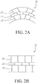
FIG. 2A and 2B are partial enlarged views of the flexible battery of this invention during bending and restoring. -
- 1
- Flexible battery
- 22
- First substrate
- 22'
- Second substrate
- 24
- Glue frame
- 30
- Electrochemical reaction element
- 302
- First active material layer
- 302'
- Second active material layer
- 304
- Intermediate layer
- a
- First interface
- b
- Second interface
- LP
- Ladder-structure cross-linked polymer
- Please refer to
FIG. 1 , the flexible battery 1 includes afirst substrate 22, a second substrate 22' and a glue frame24, wherein theglue frame 24 is sandwiched between thefirst substrate 22 and the second substrate 22' in an orthographical direction. Therefore, thefirst substrate 22, the second substrate 22' and theglue frame 24 form an enclosed space. There has anelectrochemical reaction element 30 in the enclosed space. Theelectrochemical reaction element 30 includes a firstactive material layer 302, a second active material layer 302' and anintermediate layer 304. The firstactive material layer 302 is disposed adjacent to thefirst substrate 22. The second active material layer 302' is disposed adjacent to the second substrate 22'. Theintermediate layer 304 is sandwiched between the firstactive material layer 302 and the second active material layer 302' to provide electrical insulation for electrically isolating the firstactive material layer 302 and the second active material layer 302', which located at two sides of theintermediate layer 304. There have interfaces between the firstactive material layer 302, the second active material layer 302' and theintermediate layer 304. For example, a first interface a is located between the firstactive material layer 302 and theintermediate layer 304. A second interface b is located between the second active material layer 302' and theintermediate layer 304. - In this invention, one of the first
active material layer 302, theintermediate layer 304, the second active material layer 302', the first interface a and the second interface b is added with a first adhesive. The first adhesive includes a first linear polymer and a first crystallization inhibitor, and the first adhesive contains 0.05 to 70 percent by weight of the first crystallization inhibitor. - The first crystallization inhibitor can be any additive capable of hindering the linear polymer to generate lattice orientation in it, such as a polymer with a side chain, a first cross-linked polymer, a nanoscale powder or the likes. Therefore, the first adhesive can provide good adhesion ability, and the main composition in the first adhesive, i.e. the first linear polymer, can maintain to be flexible. Moreover, the capacity of the bending strength of the electrochemical reaction element can be enhance. Therefore, the bending strength or the flexibility of the whole battery can also be increased.
- The first linear polymer is made of a liner polymer with certain flexibility. The linear polymer is selected from polyvinylidene fluoride (PVDF), poly(vinylidene fluoride-co-hexafluoropropylene) (PVDF-HFP), polytetrafluoroethylene (PTFE), acrylic acid glue, epoxy, polyethylene oxide (PEO), polyacrylonitrile (PAN), sodium carboxymethyl cellulose, styrene-butadiene rubber (SBR), polymethylacrylate, polyacrylamide, polyvinylpyrrolidone (PVP) and combinations thereof.
- The cross-linked polymer is then used as the first crystallization inhibitor as an example, but those who skilled in this art will recognize that the first crystallization inhibitor of the present invention can not be limited to only the cross-linked polymer.
- When the first crystallization inhibitor is the cross-linked polymer. The first cross-linked polymer is made of the cross-linked polymer. The cross-linked polymer is selected from epoxy, acrylic acid resin, polyacrylonitrile (PAN) and combinations thereof with network-structure, or the ladder cross-linked polymer LP, such as polyimide (PI) and derivatives thereof with ladder-structure.
- Without the presence of the crystallization inhibitor, when the heat treatment is performed to the flexible battery 1, the first linear polymer of the electrochemical reaction element would be crystallized due to its material properties. When the pressure treatment is also applied, the crystallization is more significant. Once the crystal size is too large or the degree of crystallization is too high, the formed crystals will become a steric hindrance in the structure. Therefore, the ion channels inside the flexible battery 1 are hindered, and the internal resistance of the battery is greatly increased. In addition, when the crystal size is too large or the degree of crystallization is too high, at the crystallization location, such as inside of the first
active material layer 302, the second active material layer 302',or theintermediate layer 304, or the first interface a and the second interface b, it is easy to be cracked along the grain boundary when the flexible battery 1 is bent. - However, the characteristic of the good thermal stability and heat resistance of the first cross-linked polymer are utilized in this invention. When the heat treatment is preformed to the flexible battery 1, the first cross-linked polymer can bear high temperature without melting. The first cross-linked polymer has more steric side-chains compared with the first linear polymer. Under the high temperature process, or together with high pressure, the first cross-linked polymer is served as the hindrance to the crystallization of the first linear polymer. The crystal size or the degree of crystallization of the first linear polymer can be limited, and the steric hindrance caused by crystallization can be reduced to make the ions pass more smoothly
- Moreover, when one of the first
active material layer 302, the second active material layer 302', theintermediate layer 304, the first interface a and the second interface b includes the first adhesive, one of the remaining includes a second adhesive. The second adhesive includes at least one second linear polymer and at least one second crystallization inhibitor, and the first adhesive and the second adhesive are different. For the difference, the first linear polymer and the second linear polymer may be the same, but the first crystallization inhibitor and the second crystallization inhibitor are different, or each different in weight percent within itself. Also, the first linear polymer and the second linear polymer may be different, but the first crystallization inhibitor and the second crystallization inhibitor are the same. - The compositions of the second linear polymer and the second crystallization inhibitor may be the same as the compositions of the first linear polymer and the first crystallization inhibitor of the first adhesive, and are not repeated here.
- For example, the first
active material layer 302 has the first adhesive, and theintermediate layer 304 has the second adhesive. The second adhesive consists of the second linear polymer and the second crystallization inhibitor, and the second crystallization inhibitor accounts for no less than 50% by weight of the second adhesive. The first linear polymer may be the same or different as the second linear polymer, that is, the first linear polymer may be composed of the same linear polymer as the second linear polymer, and likewise, the first crystallization inhibitor and the second crystallization inhibitor may be the same or different. - Also, the crystallization inhibitor with a side chain will have a better adhesion in Z-axis direction. For example, when the first interface a contains the first adhesive and the first crystallization inhibitor is a first cross-linked polymer, the first cross-linked polymer adhere the first
active material layer 302 to theintermediate layer 304 firmly in the Z-axis direction, such that a good electrical conductivity is maintained between the firstactive material layer 302 and theintermediate layer 304. - Furthermore, the first cross-linked polymer and/or the second cross-linked polymer may be a ladder-structure polymer, such as polyimide (PI) and derivatives thereof. This type of the cross-linked polymer has higher elasticity than the above-mentioned cross-linked polymer with network structure. Therefore, as shown in
FIG. 2A and FIG. 2B , theelectrochemical reaction element 30 can extend in the Z-axis direction without crack due to the bending stress is absorbed by the ladder-structure cross-linked polymer LP during bending of the external force. The ladder-structure cross-linked polymer LP can be restored to the original state after the external force borne by theelectrochemical reaction element 30 is removed. Therefore, the purpose of repeatedly bending without damaging theelectrochemical reaction element 30 is achieved. - The
first substrate 22 and the second substrate 22' described above may be a positive current collector or a negative current collector. For example, when thefirst substrate 22 is the positive current collector, the second substrate 22' is the negative current collector, and vice versa. The firstactive material layer 302 and the second active material layer 302' may be a positive active material layer or a negative active material layer. For example, when the firstactive material layer 302 is the positive active material layer, the second active material layer 302' is the negative active material layer, and vice versa. - In addition, the
intermediate layer 304 is a separator or an electrolyte layer of the battery. Therefore, theintermediate layer 304 has certain ionic conductivity and electrical insulation properties, and also has flexibility due to the flexible characteristics of the battery. In addition to the second linear polymer, the second cross-linked polymer accounts for no less than 50% by weight of the second adhesive. When the network-structure cross-linked polymer, such as epoxy, acrylic acid resin, or polyacrylonitrile (PAN) is utilized, the formed cross-linked structure is a network, and the overall structure is compact. The second linear polymer with linear structure is added to decrease the chance presence of a large through-hole, and enhance the electrical insulation properties. Besides, when PI with the ladder cross-linked structure is used, the holes distribution formed by ladder cross-linked structure would make the ions pass easier. Meanwhile, the ladder-structure cross-linked polymer LP has the electrically insulating property. The second adhesive is composed of the appropriate ratio of the above cross-linked polymer and the linear polymer to add into theintermediate layer 304, so that a better balance between the ion conduction and the electrical insulation in theintermediate layer 304 are achieved. - Linear polymers can be used to promote adhesion on the X-Y plane. The first cross-linked polymer and the second cross-linked polymer are composed of the cross-linked polymer. The cross-linked polymer can be used to improve the adhesion and ion conduction capability in the Z-axis direction. And, the probability or degree of the polymer crystallization generated after heat treatment or pressure treatment among the layers is disturbed or reduced. The adhesion of this invention refers to the ability of inter-layer (eg, between the substrate and the active material layer, between the active material layer and the separator) to adhere to one another, the ability of the material within layers (eg, within the active material layer or within the separator) to adhere to one another.
- Furthermore, in the present invention, one of the first
active material layer 302, the second active material layer 302', theintermediate layer 304, the first interface a and the second interface b includes the first adhesive, one of the remaining includes the second adhesive. By adjusting the ratio between the linear polymer and the cross-linked polymer in the first adhesive and/or the second adhesive, the active material layer and theintermediate layer 304 in theelectrochemical reaction element 30 can still be flexible after treating by heat or pressure and can be carried out bending many times And the crack along the grain boundary caused by the crystals generating is avoided. - Also, because the adhesive system with the crystallization inhibitor can make the layers have good adhesion and flexibility after heat treatment or pressure treatment, the flexible battery of the invention will not be easily separated from the
intermediate layer 304 when the flexible battery is bent. So that a better balance is achieved among the ions, the electrical conduction and the insulation property, and then the electrical performance of the flexible battery 1 is improved. - All of the structures, the materials and the processes disclosed herein are suitable for use in a variety of battery systems such as, for example, liquid batteries, gel batteries, solid state batteries, liquid/gel hybrid batteries, liquid/solid state hybrid batteries or gel/solid state hybrid batteries, or so-called flexible lithium batteries, flexible lithium ion batteries, flexible lithium polymer batteries, flexible lithium metal batteries, flexible lithium ceramic batteries, or flexible lithium metal ceramic batteries.
- The invention being thus described, it will be obvious that the same may be varied in many ways. Such variations are not to be regarded as a departure from the spirit and scope of the invention, and all such modifications as would be obvious to one skilled in the art are intended to be included within the scope of the following claims.
Claims (16)
- A flexible battery, comprising:a first substrate;a second substrate;a glue frame, being sandwiched between the first substrate and the second substrate in an orthographical direction to form an enclosed space;an electrochemical reaction element, disposed in the enclosed space and the electrochemical reaction element including:a first active material layer, disposed adjacent to the first substrate and electrically connected to the first substrate;a second active material layer, disposed adjacent to the second substrate and electrically connected to the second substrate;an intermediate layer, being sandwiched between the first active material layer and the second active material layer for electrically isolating the first active material layer and the second active material layer;a first interface, located between the first active material layer and the intermediate layer; anda second interface, located between the second active material layer and the intermediate layer;characterized in that:one of the first active material layer, the second active material layer, the intermediate layer, the first interface and the second interface includes a first adhesive, and the first adhesive includes at least one first linear polymer and at least one first crystallization inhibitor, wherein the first adhesive contains 0.05 to 70 percent by weight of the first crystallization inhibitor.
- The flexible battery of claim 1, wherein the first crystallization inhibitor is selected from a polymer with a side chain, a first cross-linked polymer, or a nanoscale powder.
- The flexible battery of claim 1, wherein the first substrate and the second substrate are a positive current collector and a negative current collector.
- The flexible battery of claim 1, wherein the first active material layer is a positive active material layer and the second active material layer is a negative active material layer.
- The flexible battery of claim 1, wherein the intermediate layer is a separator.
- The flexible battery of claim 1, wherein the intermediate layer is an electrolyte layer.
- The flexible battery of claim 1, wherein the first linear polymer is selected from polyvinylidene fluoride (PVDF), poly(vinylidene fluoride-co-hexafluoropropylene) (PVDF-HFP), polytetrafluoroethylene (PTFE), acrylic acid glue, epoxy, polyethylene oxide (PEO), polyacrylonitrile (PAN), sodium carboxymethyl cellulose, styrene-butadiene rubber (SBR), polymethylacrylate, polyacrylamide, polyvinylpyrrolidone (PVP) and combinations thereof.
- The flexible battery of claim 2, wherein the first cross-linked polymer is selected from epoxy, acrylic acid resin, polyacrylonitrile (PAN) and combinations thereof with network-structure.
- The flexible battery of claim 2, wherein the first cross-linked polymer is a polyimide (PI) and derivatives thereof with ladder-structure.
- The flexible battery of claim 2, wherein when one of the first active material layer, the second active material layer, the intermediate layer, the first interface and the second interface includes the first adhesive, one of the remaining includes at least one second adhesive, wherein the second adhesive includes at least one second linear polymer and at least one second crystallization inhibitor, wherein the second crystallization inhibitor is a second cross-linked polymer, and the first adhesive and the second adhesive are different.
- The flexible battery of claim 10, wherein the second linear polymer is selected from polyvinylidene fluoride (PVDF), poly(vinylidene fluoride-co-hexafluoropropylene) (PVDF-HFP), polytetrafluoroethylene (PTFE), acrylic acid glue, epoxy, polyethylene oxide (PEO), polyacrylonitrile (PAN), sodium carboxymethyl cellulose, styrene-butadiene rubber (SBR), polymethylacrylate, polyacrylamide, polyvinylpyrrolidone (PVP) and combinations thereof.
- The flexible battery of claim 10, wherein the second cross-linked polymer is selected from epoxy, acrylic acid resin, polyacrylonitrile (PAN) and combinations thereof with network-structure.
- The flexible battery of claim 10, wherein the second cross-linked polymer is a polyimide (PI) and derivatives thereof with ladder-structure.
- The flexible battery of claim 10, wherein the first linear polymer is the same as the second linear polymer.
- The flexible battery of claim 10, wherein the first cross-linked polymer is the same as the second cross-linked polymer.
- The flexible battery of claim 10, wherein the weight percent of the first cross-linked polymer in the first adhesive is different from the weight percent of the second cross-linked polymer in the second adhesive.
Applications Claiming Priority (2)
| Application Number | Priority Date | Filing Date | Title |
|---|---|---|---|
| CN201710908077.2A CN109585896A (en) | 2017-09-29 | 2017-09-29 | Flexible battery |
| PCT/CN2018/100672 WO2019062367A2 (en) | 2017-09-29 | 2018-08-15 | Flexible battery |
Publications (4)
| Publication Number | Publication Date |
|---|---|
| EP3690989A2 true EP3690989A2 (en) | 2020-08-05 |
| EP3690989A4 EP3690989A4 (en) | 2021-06-09 |
| EP3690989B1 EP3690989B1 (en) | 2024-10-09 |
| EP3690989C0 EP3690989C0 (en) | 2024-10-09 |
Family
ID=65900509
Family Applications (1)
| Application Number | Title | Priority Date | Filing Date |
|---|---|---|---|
| EP18861677.5A Active EP3690989B1 (en) | 2017-09-29 | 2018-08-15 | Flexible battery |
Country Status (14)
| Country | Link |
|---|---|
| US (1) | US12107207B2 (en) |
| EP (1) | EP3690989B1 (en) |
| JP (1) | JP6960530B2 (en) |
| KR (1) | KR102364223B1 (en) |
| CN (1) | CN109585896A (en) |
| AU (1) | AU2018342378B2 (en) |
| CA (1) | CA3076705C (en) |
| ES (1) | ES2993479T3 (en) |
| HU (1) | HUE069198T2 (en) |
| IL (1) | IL273221B2 (en) |
| MX (1) | MX2020003402A (en) |
| MY (1) | MY195469A (en) |
| RU (1) | RU2737952C1 (en) |
| WO (1) | WO2019062367A2 (en) |
Families Citing this family (1)
| Publication number | Priority date | Publication date | Assignee | Title |
|---|---|---|---|---|
| KR102890052B1 (en) * | 2020-11-02 | 2025-11-26 | 삼성전자주식회사 | Battery and electronic device including battery |
Family Cites Families (33)
| Publication number | Priority date | Publication date | Assignee | Title |
|---|---|---|---|---|
| JP3610589B2 (en) | 1994-03-10 | 2005-01-12 | ソニー株式会社 | Non-aqueous electrolyte secondary battery |
| US5558957A (en) * | 1994-10-26 | 1996-09-24 | International Business Machines Corporation | Method for making a thin flexible primary battery for microelectronics applications |
| US5939223A (en) * | 1996-10-08 | 1999-08-17 | International Business Machines Corporation | Lithium polymer electrolyte battery for sub-ambient temperature applications |
| JPH10172573A (en) * | 1996-12-13 | 1998-06-26 | Furukawa Electric Co Ltd:The | Negative electrode for lithium secondary battery, method for producing the same, and secondary battery using the same |
| JP2003257488A (en) * | 2002-02-27 | 2003-09-12 | Nippon Zeon Co Ltd | Polymer gel electrolyte |
| US20140162108A1 (en) * | 2005-08-09 | 2014-06-12 | Polyplus Battery Company | Lithium battery with hermetically sealed anode |
| CN100397700C (en) * | 2005-11-18 | 2008-06-25 | 中国科学院上海微系统与信息技术研究所 | Thin lithium ion battery and preparation method thereof |
| JP5202824B2 (en) * | 2006-07-14 | 2013-06-05 | Necエナジーデバイス株式会社 | Nonaqueous electrolyte secondary battery |
| US9105930B2 (en) | 2006-12-18 | 2015-08-11 | Prologium Holding Inc. | Electricity supply system and electricity supply element thereof |
| CN101207222B (en) * | 2006-12-22 | 2011-03-16 | 辉能科技股份有限公司 | power supply system |
| FR2912555B1 (en) * | 2007-02-09 | 2011-02-25 | Commissariat Energie Atomique | ELECTROCHEMICAL SYSTEM ELECTRODE BINDER, ELECTRODE COMPRISING THE BINDER, AND ELECTROCHEMICAL SYSTEM COMPRISING THE ELECTRODE. |
| US9231239B2 (en) | 2007-05-30 | 2016-01-05 | Prologium Holding Inc. | Electricity supply element and ceramic separator thereof |
| US9570728B2 (en) | 2007-05-30 | 2017-02-14 | Prologium Holding Inc. | Electricity supply element and ceramic separator thereof |
| JP5317435B2 (en) | 2007-06-22 | 2013-10-16 | パナソニック株式会社 | Negative electrode active material for all solid polymer battery and all solid polymer battery |
| KR101002161B1 (en) | 2007-11-29 | 2010-12-17 | 주식회사 엘지화학 | Separator with a porous coating layer, a manufacturing method and an electrochemical device having the same |
| JP4803240B2 (en) * | 2008-11-26 | 2011-10-26 | ソニー株式会社 | Nonaqueous electrolyte secondary battery |
| TWI406444B (en) | 2010-03-05 | 2013-08-21 | Prologium Technology Co | Package structure and its related electricity supply system |
| CN201673947U (en) * | 2010-04-30 | 2010-12-15 | 辉能科技股份有限公司 | Packaging structure of electric energy supply system |
| JP5573980B2 (en) | 2012-01-24 | 2014-08-20 | ダイキン工業株式会社 | Binder, positive electrode mixture and negative electrode mixture |
| CN107452928B (en) * | 2012-02-07 | 2021-07-27 | 辉能科技股份有限公司 | Power supply system and its ceramic isolation layer |
| KR101968640B1 (en) * | 2012-04-03 | 2019-04-12 | 삼성전자주식회사 | Flexible secondary battery |
| JP5673648B2 (en) * | 2012-04-27 | 2015-02-18 | 株式会社豊田自動織機 | Positive electrode for secondary battery, method for producing the same, and non-aqueous secondary battery |
| KR101315672B1 (en) | 2012-07-06 | 2013-10-08 | (주)오렌지파워 | Electrode assembly, battery having the same and method of fabricating battery |
| US20150207167A1 (en) | 2012-09-24 | 2015-07-23 | Panasonic Intellectual Property Management Co., Ltd. | Thin battery and production method thereof |
| HUE042852T2 (en) * | 2012-10-26 | 2019-07-29 | Fujifilm Wako Pure Chemical Corp | Use of crosslinked polyacrylic acid in a binder for a lithium battery |
| US9564660B2 (en) * | 2013-06-27 | 2017-02-07 | QingHong Technology Co., Ltd. | Electric core for thin film battery |
| US9383593B2 (en) * | 2014-08-21 | 2016-07-05 | Johnson & Johnson Vision Care, Inc. | Methods to form biocompatible energization elements for biomedical devices comprising laminates and placed separators |
| US9899700B2 (en) * | 2014-08-21 | 2018-02-20 | Johnson & Johnson Vision Care, Inc. | Methods to form biocompatible energization elements for biomedical devices comprising laminates and deposited separators |
| CN106340613B (en) * | 2015-07-13 | 2019-11-05 | 宁德时代新能源科技股份有限公司 | Negative plate and lithium ion battery |
| US11118014B2 (en) * | 2016-10-06 | 2021-09-14 | Kabushiki Kaisha Toyota Jidoshokki | Polymer compound, intermediate composition, negative electrode, electricity storage device, and method for producing polymer compound |
| CN106784993A (en) * | 2016-12-29 | 2017-05-31 | 中国电子科技集团公司第十八研究所 | Flexible polymer thin lithium ion battery and preparation method thereof |
| CN106866846B (en) * | 2017-03-09 | 2020-09-08 | 宣城研一新能源科技有限公司 | Aqueous binder for lithium ion battery, preparation method of aqueous binder and lithium ion battery pole piece |
| CN115528379A (en) * | 2018-04-11 | 2022-12-27 | 宁德新能源科技有限公司 | Isolating membrane and energy storage device |
-
2017
- 2017-09-29 CN CN201710908077.2A patent/CN109585896A/en active Pending
-
2018
- 2018-08-15 CA CA3076705A patent/CA3076705C/en active Active
- 2018-08-15 EP EP18861677.5A patent/EP3690989B1/en active Active
- 2018-08-15 MY MYPI2020001454A patent/MY195469A/en unknown
- 2018-08-15 US US16/646,421 patent/US12107207B2/en active Active
- 2018-08-15 AU AU2018342378A patent/AU2018342378B2/en active Active
- 2018-08-15 HU HUE18861677A patent/HUE069198T2/en unknown
- 2018-08-15 RU RU2020113235A patent/RU2737952C1/en active
- 2018-08-15 KR KR1020207009722A patent/KR102364223B1/en active Active
- 2018-08-15 MX MX2020003402A patent/MX2020003402A/en unknown
- 2018-08-15 IL IL273221A patent/IL273221B2/en unknown
- 2018-08-15 JP JP2020517518A patent/JP6960530B2/en active Active
- 2018-08-15 ES ES18861677T patent/ES2993479T3/en active Active
- 2018-08-15 WO PCT/CN2018/100672 patent/WO2019062367A2/en not_active Ceased
Also Published As
| Publication number | Publication date |
|---|---|
| CA3076705C (en) | 2021-12-14 |
| IL273221B2 (en) | 2024-04-01 |
| EP3690989B1 (en) | 2024-10-09 |
| AU2018342378A1 (en) | 2020-03-26 |
| ES2993479T3 (en) | 2024-12-30 |
| JP6960530B2 (en) | 2021-11-05 |
| KR20200081358A (en) | 2020-07-07 |
| CA3076705A1 (en) | 2019-04-04 |
| MY195469A (en) | 2023-01-26 |
| AU2018342378B2 (en) | 2021-12-02 |
| KR102364223B1 (en) | 2022-02-16 |
| WO2019062367A3 (en) | 2019-07-25 |
| IL273221B1 (en) | 2023-12-01 |
| IL273221A (en) | 2020-04-30 |
| EP3690989A4 (en) | 2021-06-09 |
| CN109585896A (en) | 2019-04-05 |
| BR112020006178A2 (en) | 2020-12-01 |
| MX2020003402A (en) | 2020-07-20 |
| RU2737952C1 (en) | 2020-12-07 |
| HUE069198T2 (en) | 2025-02-28 |
| US12107207B2 (en) | 2024-10-01 |
| WO2019062367A2 (en) | 2019-04-04 |
| JP2020535609A (en) | 2020-12-03 |
| EP3690989C0 (en) | 2024-10-09 |
| US20200280089A1 (en) | 2020-09-03 |
Similar Documents
| Publication | Publication Date | Title |
|---|---|---|
| JP6856042B2 (en) | All solid state battery | |
| US20090136839A1 (en) | Thin film battery comprising stacked battery cells and method | |
| JP5492999B2 (en) | Cable type secondary battery | |
| KR20160002988A (en) | Electrochemical cell with solid and liquid electrolytes | |
| JP2019110130A (en) | Manufacture of solid state battery | |
| JP2018181451A (en) | Stacked all solid state battery and method of manufacturing the same | |
| KR102124057B1 (en) | All solid battery | |
| KR101493584B1 (en) | Electricity supply element and ceramic separator thereof | |
| CN114824336B (en) | Solid-state batteries and solid-state battery cells | |
| CN107452928B (en) | Power supply system and its ceramic isolation layer | |
| JP2019186102A (en) | Laminated battery | |
| JP2020087584A (en) | Lithium secondary battery and method for manufacturing the same | |
| CN118472347B (en) | Battery preparation method, battery and power utilization device | |
| US12107207B2 (en) | Flexible battery | |
| CN120357160B (en) | All-solid-state battery, and preparation method and application thereof | |
| CN210692707U (en) | Solid-state battery cells, laminated battery cells and composite power battery cells | |
| CN112103567A (en) | Solid-state battery cell, laminated battery cell and composite power battery cell based on composite material electrode | |
| AU2020100433A4 (en) | Flexible Battery | |
| TWI664253B (en) | Flexible battery | |
| EP4213270B1 (en) | ELECTRODE ARRANGEMENT FOR SECONDARY BATTERY AND SECONDARY BATTERY SO THAT | |
| BR112020006178B1 (en) | FLEXIBLE BATTERY | |
| KR20230045568A (en) | Electrode assembly for a rechargeable battery and a rechargeable battery comprising the same | |
| JP2025535067A (en) | Electrode assembly for a secondary battery including a current limiter | |
| JP2011065840A (en) | Electrode for lithium ion secondary battery |
Legal Events
| Date | Code | Title | Description |
|---|---|---|---|
| STAA | Information on the status of an ep patent application or granted ep patent |
Free format text: STATUS: THE INTERNATIONAL PUBLICATION HAS BEEN MADE |
|
| PUAI | Public reference made under article 153(3) epc to a published international application that has entered the european phase |
Free format text: ORIGINAL CODE: 0009012 |
|
| STAA | Information on the status of an ep patent application or granted ep patent |
Free format text: STATUS: REQUEST FOR EXAMINATION WAS MADE |
|
| 17P | Request for examination filed |
Effective date: 20200330 |
|
| AK | Designated contracting states |
Kind code of ref document: A2 Designated state(s): AL AT BE BG CH CY CZ DE DK EE ES FI FR GB GR HR HU IE IS IT LI LT LU LV MC MK MT NL NO PL PT RO RS SE SI SK SM TR |
|
| AX | Request for extension of the european patent |
Extension state: BA ME |
|
| DAV | Request for validation of the european patent (deleted) | ||
| DAX | Request for extension of the european patent (deleted) | ||
| REG | Reference to a national code |
Ref country code: DE Free format text: PREVIOUS MAIN CLASS: H01M0002340000 Ipc: H01M0010058000 Ref country code: DE Ref legal event code: R079 Ref document number: 602018075331 Country of ref document: DE Free format text: PREVIOUS MAIN CLASS: H01M0002340000 Ipc: H01M0010058000 |
|
| A4 | Supplementary search report drawn up and despatched |
Effective date: 20210511 |
|
| RIC1 | Information provided on ipc code assigned before grant |
Ipc: H01M 10/058 20100101AFI20210504BHEP Ipc: H01M 4/62 20060101ALI20210504BHEP Ipc: H01M 10/0585 20100101ALI20210504BHEP Ipc: H01M 50/46 20210101ALI20210504BHEP Ipc: H01M 10/052 20100101ALI20210504BHEP Ipc: H01M 10/04 20060101ALI20210504BHEP |
|
| STAA | Information on the status of an ep patent application or granted ep patent |
Free format text: STATUS: EXAMINATION IS IN PROGRESS |
|
| 17Q | First examination report despatched |
Effective date: 20230602 |
|
| GRAP | Despatch of communication of intention to grant a patent |
Free format text: ORIGINAL CODE: EPIDOSNIGR1 |
|
| STAA | Information on the status of an ep patent application or granted ep patent |
Free format text: STATUS: GRANT OF PATENT IS INTENDED |
|
| RIC1 | Information provided on ipc code assigned before grant |
Ipc: H01M 10/04 20060101ALI20240301BHEP Ipc: H01M 10/052 20100101ALI20240301BHEP Ipc: H01M 50/46 20210101ALI20240301BHEP Ipc: H01M 10/0585 20100101ALI20240301BHEP Ipc: H01M 4/62 20060101ALI20240301BHEP Ipc: H01M 10/058 20100101AFI20240301BHEP |
|
| INTG | Intention to grant announced |
Effective date: 20240405 |
|
| GRAS | Grant fee paid |
Free format text: ORIGINAL CODE: EPIDOSNIGR3 |
|
| GRAA | (expected) grant |
Free format text: ORIGINAL CODE: 0009210 |
|
| STAA | Information on the status of an ep patent application or granted ep patent |
Free format text: STATUS: THE PATENT HAS BEEN GRANTED |
|
| AK | Designated contracting states |
Kind code of ref document: B1 Designated state(s): AL AT BE BG CH CY CZ DE DK EE ES FI FR GB GR HR HU IE IS IT LI LT LU LV MC MK MT NL NO PL PT RO RS SE SI SK SM TR |
|
| REG | Reference to a national code |
Ref country code: CH Ref legal event code: EP |
|
| REG | Reference to a national code |
Ref country code: DE Ref legal event code: R096 Ref document number: 602018075331 Country of ref document: DE |
|
| REG | Reference to a national code |
Ref country code: IE Ref legal event code: FG4D |
|
| U01 | Request for unitary effect filed |
Effective date: 20241025 |
|
| U07 | Unitary effect registered |
Designated state(s): AT BE BG DE DK EE FI FR IT LT LU LV MT NL PT RO SE SI Effective date: 20241107 |
|
| REG | Reference to a national code |
Ref country code: ES Ref legal event code: FG2A Ref document number: 2993479 Country of ref document: ES Kind code of ref document: T3 Effective date: 20241230 |
|
| REG | Reference to a national code |
Ref country code: HU Ref legal event code: AG4A Ref document number: E069198 Country of ref document: HU |
|
| PG25 | Lapsed in a contracting state [announced via postgrant information from national office to epo] |
Ref country code: HR Free format text: LAPSE BECAUSE OF FAILURE TO SUBMIT A TRANSLATION OF THE DESCRIPTION OR TO PAY THE FEE WITHIN THE PRESCRIBED TIME-LIMIT Effective date: 20241009 Ref country code: IS Free format text: LAPSE BECAUSE OF FAILURE TO SUBMIT A TRANSLATION OF THE DESCRIPTION OR TO PAY THE FEE WITHIN THE PRESCRIBED TIME-LIMIT Effective date: 20250209 |
|
| PG25 | Lapsed in a contracting state [announced via postgrant information from national office to epo] |
Ref country code: NO Free format text: LAPSE BECAUSE OF FAILURE TO SUBMIT A TRANSLATION OF THE DESCRIPTION OR TO PAY THE FEE WITHIN THE PRESCRIBED TIME-LIMIT Effective date: 20250109 |
|
| PG25 | Lapsed in a contracting state [announced via postgrant information from national office to epo] |
Ref country code: GR Free format text: LAPSE BECAUSE OF FAILURE TO SUBMIT A TRANSLATION OF THE DESCRIPTION OR TO PAY THE FEE WITHIN THE PRESCRIBED TIME-LIMIT Effective date: 20250110 |
|
| PG25 | Lapsed in a contracting state [announced via postgrant information from national office to epo] |
Ref country code: PL Free format text: LAPSE BECAUSE OF FAILURE TO SUBMIT A TRANSLATION OF THE DESCRIPTION OR TO PAY THE FEE WITHIN THE PRESCRIBED TIME-LIMIT Effective date: 20241009 |
|
| PG25 | Lapsed in a contracting state [announced via postgrant information from national office to epo] |
Ref country code: RS Free format text: LAPSE BECAUSE OF FAILURE TO SUBMIT A TRANSLATION OF THE DESCRIPTION OR TO PAY THE FEE WITHIN THE PRESCRIBED TIME-LIMIT Effective date: 20250109 |
|
| PG25 | Lapsed in a contracting state [announced via postgrant information from national office to epo] |
Ref country code: SM Free format text: LAPSE BECAUSE OF FAILURE TO SUBMIT A TRANSLATION OF THE DESCRIPTION OR TO PAY THE FEE WITHIN THE PRESCRIBED TIME-LIMIT Effective date: 20241009 |
|
| PG25 | Lapsed in a contracting state [announced via postgrant information from national office to epo] |
Ref country code: SK Free format text: LAPSE BECAUSE OF FAILURE TO SUBMIT A TRANSLATION OF THE DESCRIPTION OR TO PAY THE FEE WITHIN THE PRESCRIBED TIME-LIMIT Effective date: 20241009 |
|
| PG25 | Lapsed in a contracting state [announced via postgrant information from national office to epo] |
Ref country code: CZ Free format text: LAPSE BECAUSE OF FAILURE TO SUBMIT A TRANSLATION OF THE DESCRIPTION OR TO PAY THE FEE WITHIN THE PRESCRIBED TIME-LIMIT Effective date: 20241009 |
|
| PLBE | No opposition filed within time limit |
Free format text: ORIGINAL CODE: 0009261 |
|
| STAA | Information on the status of an ep patent application or granted ep patent |
Free format text: STATUS: NO OPPOSITION FILED WITHIN TIME LIMIT |
|
| 26N | No opposition filed |
Effective date: 20250710 |
|
| PGFP | Annual fee paid to national office [announced via postgrant information from national office to epo] |
Ref country code: HU Payment date: 20250724 Year of fee payment: 8 |
|
| U20 | Renewal fee for the european patent with unitary effect paid |
Year of fee payment: 8 Effective date: 20250828 |
|
| PGFP | Annual fee paid to national office [announced via postgrant information from national office to epo] |
Ref country code: ES Payment date: 20250902 Year of fee payment: 8 |
|
| PGFP | Annual fee paid to national office [announced via postgrant information from national office to epo] |
Ref country code: GB Payment date: 20250826 Year of fee payment: 8 |
|
| REG | Reference to a national code |
Ref country code: CH Ref legal event code: H13 Free format text: ST27 STATUS EVENT CODE: U-0-0-H10-H13 (AS PROVIDED BY THE NATIONAL OFFICE) Effective date: 20260324 |
|
| PG25 | Lapsed in a contracting state [announced via postgrant information from national office to epo] |
Ref country code: MC Free format text: LAPSE BECAUSE OF FAILURE TO SUBMIT A TRANSLATION OF THE DESCRIPTION OR TO PAY THE FEE WITHIN THE PRESCRIBED TIME-LIMIT Effective date: 20241009 |
|
| PG25 | Lapsed in a contracting state [announced via postgrant information from national office to epo] |
Ref country code: CH Free format text: LAPSE BECAUSE OF NON-PAYMENT OF DUE FEES Effective date: 20250831 |