EP3690980A1 - Vehicle lower structure - Google Patents
Vehicle lower structure Download PDFInfo
- Publication number
- EP3690980A1 EP3690980A1 EP20150866.0A EP20150866A EP3690980A1 EP 3690980 A1 EP3690980 A1 EP 3690980A1 EP 20150866 A EP20150866 A EP 20150866A EP 3690980 A1 EP3690980 A1 EP 3690980A1
- Authority
- EP
- European Patent Office
- Prior art keywords
- battery stack
- vehicle
- stage
- stage battery
- width direction
- Prior art date
- Legal status (The legal status is an assumption and is not a legal conclusion. Google has not performed a legal analysis and makes no representation as to the accuracy of the status listed.)
- Granted
Links
- 238000000926 separation method Methods 0.000 claims abstract description 12
- 230000003014 reinforcing effect Effects 0.000 claims abstract description 8
- 229910000831 Steel Inorganic materials 0.000 description 10
- 230000005540 biological transmission Effects 0.000 description 10
- 239000010959 steel Substances 0.000 description 10
- 230000008859 change Effects 0.000 description 3
- 229910052751 metal Inorganic materials 0.000 description 3
- 239000002184 metal Substances 0.000 description 3
- 239000000725 suspension Substances 0.000 description 3
- XEEYBQQBJWHFJM-UHFFFAOYSA-N Iron Chemical compound [Fe] XEEYBQQBJWHFJM-UHFFFAOYSA-N 0.000 description 2
- 238000001816 cooling Methods 0.000 description 2
- 230000017525 heat dissipation Effects 0.000 description 2
- 239000000463 material Substances 0.000 description 2
- 239000011347 resin Substances 0.000 description 2
- 229920005989 resin Polymers 0.000 description 2
- 229910052782 aluminium Inorganic materials 0.000 description 1
- XAGFODPZIPBFFR-UHFFFAOYSA-N aluminium Chemical compound [Al] XAGFODPZIPBFFR-UHFFFAOYSA-N 0.000 description 1
- 230000008901 benefit Effects 0.000 description 1
- 230000003247 decreasing effect Effects 0.000 description 1
- 238000007599 discharging Methods 0.000 description 1
- 229910052742 iron Inorganic materials 0.000 description 1
- 230000007246 mechanism Effects 0.000 description 1
- 238000000034 method Methods 0.000 description 1
- 238000012986 modification Methods 0.000 description 1
- 230000004048 modification Effects 0.000 description 1
- 230000008569 process Effects 0.000 description 1
- 230000001737 promoting effect Effects 0.000 description 1
- 230000002787 reinforcement Effects 0.000 description 1
Images


Classifications
-
- B—PERFORMING OPERATIONS; TRANSPORTING
- B60—VEHICLES IN GENERAL
- B60K—ARRANGEMENT OR MOUNTING OF PROPULSION UNITS OR OF TRANSMISSIONS IN VEHICLES; ARRANGEMENT OR MOUNTING OF PLURAL DIVERSE PRIME-MOVERS IN VEHICLES; AUXILIARY DRIVES FOR VEHICLES; INSTRUMENTATION OR DASHBOARDS FOR VEHICLES; ARRANGEMENTS IN CONNECTION WITH COOLING, AIR INTAKE, GAS EXHAUST OR FUEL SUPPLY OF PROPULSION UNITS IN VEHICLES
- B60K1/00—Arrangement or mounting of electrical propulsion units
- B60K1/04—Arrangement or mounting of electrical propulsion units of the electric storage means for propulsion
-
- B—PERFORMING OPERATIONS; TRANSPORTING
- B60—VEHICLES IN GENERAL
- B60L—PROPULSION OF ELECTRICALLY-PROPELLED VEHICLES; SUPPLYING ELECTRIC POWER FOR AUXILIARY EQUIPMENT OF ELECTRICALLY-PROPELLED VEHICLES; ELECTRODYNAMIC BRAKE SYSTEMS FOR VEHICLES IN GENERAL; MAGNETIC SUSPENSION OR LEVITATION FOR VEHICLES; MONITORING OPERATING VARIABLES OF ELECTRICALLY-PROPELLED VEHICLES; ELECTRIC SAFETY DEVICES FOR ELECTRICALLY-PROPELLED VEHICLES
- B60L50/00—Electric propulsion with power supplied within the vehicle
- B60L50/50—Electric propulsion with power supplied within the vehicle using propulsion power supplied by batteries or fuel cells
- B60L50/60—Electric propulsion with power supplied within the vehicle using propulsion power supplied by batteries or fuel cells using power supplied by batteries
- B60L50/64—Constructional details of batteries specially adapted for electric vehicles
-
- B—PERFORMING OPERATIONS; TRANSPORTING
- B60—VEHICLES IN GENERAL
- B60L—PROPULSION OF ELECTRICALLY-PROPELLED VEHICLES; SUPPLYING ELECTRIC POWER FOR AUXILIARY EQUIPMENT OF ELECTRICALLY-PROPELLED VEHICLES; ELECTRODYNAMIC BRAKE SYSTEMS FOR VEHICLES IN GENERAL; MAGNETIC SUSPENSION OR LEVITATION FOR VEHICLES; MONITORING OPERATING VARIABLES OF ELECTRICALLY-PROPELLED VEHICLES; ELECTRIC SAFETY DEVICES FOR ELECTRICALLY-PROPELLED VEHICLES
- B60L50/00—Electric propulsion with power supplied within the vehicle
- B60L50/50—Electric propulsion with power supplied within the vehicle using propulsion power supplied by batteries or fuel cells
- B60L50/60—Electric propulsion with power supplied within the vehicle using propulsion power supplied by batteries or fuel cells using power supplied by batteries
- B60L50/66—Arrangements of batteries
-
- B—PERFORMING OPERATIONS; TRANSPORTING
- B62—LAND VEHICLES FOR TRAVELLING OTHERWISE THAN ON RAILS
- B62D—MOTOR VEHICLES; TRAILERS
- B62D21/00—Understructures, i.e. chassis frame on which a vehicle body may be mounted
- B62D21/15—Understructures, i.e. chassis frame on which a vehicle body may be mounted having impact absorbing means, e.g. a frame designed to permanently or temporarily change shape or dimension upon impact with another body
- B62D21/157—Understructures, i.e. chassis frame on which a vehicle body may be mounted having impact absorbing means, e.g. a frame designed to permanently or temporarily change shape or dimension upon impact with another body for side impacts
-
- B—PERFORMING OPERATIONS; TRANSPORTING
- B62—LAND VEHICLES FOR TRAVELLING OTHERWISE THAN ON RAILS
- B62D—MOTOR VEHICLES; TRAILERS
- B62D25/00—Superstructure or monocoque structure sub-units; Parts or details thereof not otherwise provided for
- B62D25/20—Floors or bottom sub-units
-
- B—PERFORMING OPERATIONS; TRANSPORTING
- B62—LAND VEHICLES FOR TRAVELLING OTHERWISE THAN ON RAILS
- B62D—MOTOR VEHICLES; TRAILERS
- B62D27/00—Connections between superstructure or understructure sub-units
- B62D27/06—Connections between superstructure or understructure sub-units readily releasable
- B62D27/065—Connections between superstructure or understructure sub-units readily releasable using screwthread
-
- H—ELECTRICITY
- H01—ELECTRIC ELEMENTS
- H01M—PROCESSES OR MEANS, e.g. BATTERIES, FOR THE DIRECT CONVERSION OF CHEMICAL ENERGY INTO ELECTRICAL ENERGY
- H01M50/00—Constructional details or processes of manufacture of the non-active parts of electrochemical cells other than fuel cells, e.g. hybrid cells
- H01M50/20—Mountings; Secondary casings or frames; Racks, modules or packs; Suspension devices; Shock absorbers; Transport or carrying devices; Holders
- H01M50/249—Mountings; Secondary casings or frames; Racks, modules or packs; Suspension devices; Shock absorbers; Transport or carrying devices; Holders specially adapted for aircraft or vehicles, e.g. cars or trains
-
- B—PERFORMING OPERATIONS; TRANSPORTING
- B60—VEHICLES IN GENERAL
- B60K—ARRANGEMENT OR MOUNTING OF PROPULSION UNITS OR OF TRANSMISSIONS IN VEHICLES; ARRANGEMENT OR MOUNTING OF PLURAL DIVERSE PRIME-MOVERS IN VEHICLES; AUXILIARY DRIVES FOR VEHICLES; INSTRUMENTATION OR DASHBOARDS FOR VEHICLES; ARRANGEMENTS IN CONNECTION WITH COOLING, AIR INTAKE, GAS EXHAUST OR FUEL SUPPLY OF PROPULSION UNITS IN VEHICLES
- B60K1/00—Arrangement or mounting of electrical propulsion units
- B60K1/04—Arrangement or mounting of electrical propulsion units of the electric storage means for propulsion
- B60K2001/0405—Arrangement or mounting of electrical propulsion units of the electric storage means for propulsion characterised by their position
- B60K2001/0433—Arrangement under the rear seats
-
- B—PERFORMING OPERATIONS; TRANSPORTING
- B60—VEHICLES IN GENERAL
- B60K—ARRANGEMENT OR MOUNTING OF PROPULSION UNITS OR OF TRANSMISSIONS IN VEHICLES; ARRANGEMENT OR MOUNTING OF PLURAL DIVERSE PRIME-MOVERS IN VEHICLES; AUXILIARY DRIVES FOR VEHICLES; INSTRUMENTATION OR DASHBOARDS FOR VEHICLES; ARRANGEMENTS IN CONNECTION WITH COOLING, AIR INTAKE, GAS EXHAUST OR FUEL SUPPLY OF PROPULSION UNITS IN VEHICLES
- B60K1/00—Arrangement or mounting of electrical propulsion units
- B60K1/04—Arrangement or mounting of electrical propulsion units of the electric storage means for propulsion
- B60K2001/0405—Arrangement or mounting of electrical propulsion units of the electric storage means for propulsion characterised by their position
- B60K2001/0438—Arrangement under the floor
-
- B—PERFORMING OPERATIONS; TRANSPORTING
- B60—VEHICLES IN GENERAL
- B60Y—INDEXING SCHEME RELATING TO ASPECTS CROSS-CUTTING VEHICLE TECHNOLOGY
- B60Y2306/00—Other features of vehicle sub-units
- B60Y2306/01—Reducing damages in case of crash, e.g. by improving battery protection
-
- H—ELECTRICITY
- H01—ELECTRIC ELEMENTS
- H01M—PROCESSES OR MEANS, e.g. BATTERIES, FOR THE DIRECT CONVERSION OF CHEMICAL ENERGY INTO ELECTRICAL ENERGY
- H01M2200/00—Safety devices for primary or secondary batteries
- H01M2200/20—Pressure-sensitive devices
Definitions
- the present disclosure relates to a vehicle lower structure in which a battery is stored under a floor of a vehicle.
- a battery is mounted as a power source for the vehicle.
- a battery pack is stored under a floor panel that constitutes a floor surface of a vehicle chamber.
- the battery pack which is a heavy weight, is fixed to a framework member of the vehicle.
- a lower frame that is the framework member is provided on a bottom surface of the battery pack, and the lower frame projects outward from the battery pack in a vehicle width direction.
- a pair of side members that are the framework members are provided on both sides of the floor panel in the vehicle width direction and extend in a vehicle front-rear direction. Portions of the lower frame that project from the battery pack are fastened to the side members with nuts and bolts or the like.
- a plurality of battery stacks are stored in the battery pack.
- arrangement of the battery stacks is determined to follow a floor shape of the vehicle. For example, a floor surface of a luggage space behind the vehicle chamber is raised above a floor surface of a passenger space.
- the battery stacks are stacked in two stages, upper and lower.
- the upper-stage battery stack is separated from the lower-stage battery stack in a vehicle height direction.
- a bracket that is a support member extends from a bottom surface of a case tray that stores the battery stack in a vehicle height direction, and the upper-stage battery stack is supported (raised and supported) by the bracket.
- the battery pack is disposed between the pair of side members. At this time, a position of at least a part of the battery pack matches a position of each side member in a vehicle height direction.
- side collision When collision of a side surface of the vehicle (hereinafter appropriately referred to as side collision) occurs in such an arrangement as described above, the battery pack that is the heavy weight is energized in the vehicle width direction due to inertia (laterally shaken). At this time, there is concern that the upper-stage battery stack comes in contact with the side member that is present on a side of the battery stack.
- the lower-stage battery stack is fixed to a lower arm, and the lower arm is fixed to the side member. Therefore, there is structurally low possibility that the lower-stage battery stack comes in contact with the side member.
- the upper-stage battery stack is fixed to the lower arm via a support member such as the bracket in a state where the battery stack is separated (floated) from the lower-stage battery stack.
- the bracket undergoes buckling deformation, depending on a strength of the bracket. Consequently, there is concern that the upper-stage battery stack moves in the vehicle width direction to be in contact with the side member as it is.
- the strength of the bracket (the support member) is increased, for example, by use of a steel plate having a large thickness.
- change in thickness also causes increase in weight of the upper-stage battery pack, and a complicated operation of calculating the strength again to change the thickness is required to cope with such change in design.
- the present disclosure relates to a vehicle lower structure.
- the structure comprises a battery pack, a lower frame, and a pair of side frames.
- the battery pack is stored under a floor panel.
- the lower frame is a framework member provided on a bottom surface of the battery pack, and having fastening portions formed at both ends that project outward from the battery pack in a vehicle width direction.
- a pair of side members are framework members that are provided on both sides of the floor panel in the vehicle width direction and extend in a vehicle front-rear direction, and to which the fastening portions of the lower frame are fastened.
- the battery pack comprises a lower-stage battery stack fixed to the lower frame, and an upper-stage battery stack mounted in an upper stage of the lower-stage battery stack.
- the upper-stage battery stack is separated from the lower-stage battery stack in a vehicle height direction. Furthermore, a reinforcing member is arranged at a height position that matches a height position of a separation space between the upper-stage battery stack and the lower-stage battery stack in the vehicle height direction.
- the reinforcing member comprises a pair of transverse frames extending in the vehicle width direction and provided in the vehicle front-rear direction, and a pair of longitudinal frames connected to both ends of the pair of transverse frames in the vehicle width direction and extending in the vehicle front-rear direction, and the longitudinal frames project outward from the upper-stage battery stack in the vehicle width direction.
- the longitudinal frames of the reinforcing member project outward from the upper-stage battery stack in the vehicle width direction, and therefore come in contact with the side members ahead of the upper-stage battery stack during side collision. Furthermore, the longitudinal frames are provided so that they match, in height, the separation space between the upper-stage battery stack and the lower-stage battery stack in the vehicle height direction, and the upper-stage battery stack and the lower-stage battery stack are arranged to avoid the longitudinal frames in the vehicle height direction. Therefore, loads received by the longitudinal frames in the vehicle width direction are transmitted to the transverse frames, while the loads are inhibited from being transmitted to the upper-stage battery stack and the lower-stage battery stack.
- each longitudinal frame may include an overlap region that is aligned with the side member in terms of a position in the vehicle height direction.
- an auxiliary member may be provided to project further outward from the overlap region of the longitudinal frame in the vehicle width direction.
- a projection width in the vehicle width direction is expanded by the auxiliary member, thereby avoiding proximity of each side member to the upper-stage battery stack. Furthermore, the auxiliary member is provided only in the overlap region. Consequently, increase in weight of the member may be suppressed, as compared with, for example, a case where the auxiliary member is provided over an entire length of the longitudinal frame in a longitudinal direction.
- the battery pack may comprise a case tray that stores the upper-stage battery stack and the lower-stage battery stack.
- the upper-stage battery stack is fixed to an upper end of a plate-shaped bracket extending upward from the case tray in the vehicle front-rear direction.
- a ridgeline is formed on the bracket across the vehicle front-rear direction.
- the ridgeline is provided across the vehicle front-rear direction. Consequently, rigidity of the bracket in the vehicle front-rear direction improves.
- the ridgeline across the vehicle front-rear direction becomes a starting point of buckling deformation of the bracket during side collision.
- the auxiliary member collides with the side members ahead of the upper-stage battery stack as described above. Consequently, transmission of a collision load to the upper-stage battery stack is inhibited.
- FIG. 1 to FIG. 12 illustrate a vehicle lower structure according to an embodiment of the present invention.
- a vehicle front-rear direction is shown by an axis denoted with symbol FR
- a vehicle width direction is shown by an axis denoted with symbol RW
- a vehicle up-down direction is shown by an axis denoted with symbol UP.
- a vehicle front direction is a forward direction.
- a right width direction is a forward direction.
- an up direction is a forward direction.
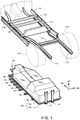
- FIG. 1 illustrates an exploded perspective view of the vehicle lower structure according to the present embodiment.
- the vehicle lower structure according to the present embodiment is mounted in, for example, an electric car.
- the vehicle lower structure comprises a battery pack 10, a lower frame 30, a front side member 110, and a rear side member 112.
- FIG. 1 illustrates the battery pack 10 and framework members of a vehicle which support this battery pack, and secondarily shows a panel member and rear tires 118 by broken lines.
- the framework members of the vehicle comprise a pair of the front side members 110, 110, a pair of the rear side members 112, 112, and a pair of rockers 116, 116 as "longitudinal frames" extending in the vehicle front-rear direction.
- the framework members of the vehicle comprise a center floor cross member 113 and a rear cross member 114 as "transverse frames" extending in the vehicle width direction.
- Each of these members is constituted of, for example, a high-tensile steel plate or a hot stamp steel plate.
- Both the pair of front side members 110 and the pair of rear side members 112 are framework members provided on both sides of a floor panel 120 (see FIG. 3 ) in the vehicle width direction and extending in the vehicle front-rear direction.
- the front side members 110 and the rear side members 112 may be grasped together as pairs of side members extending in the vehicle front-rear direction.
- the pair of front side members 110, 110 extend from a front compartment (not shown) ahead of a vehicle chamber to the center floor cross member 113 in the vehicle chamber. Furthermore, referring to FIG. 3 , fastening portions 36 of the lower frame 30 are fastened to the front side members 110, 110. This fastening structure will be described later.
- each of the front side members 110, 110 comprises a front side upper member 110A that is an upper member and a front side lower member 110B that is a lower member.
- Each of the front side upper member 110A and the front side lower member 110B has a hat-shaped section, and the two members are superimposed onto each other to constitute a closed section.
- front ends of the pair of rear side members 112, 112 are connected to rear ends of the front side members 110, 110.
- each of the rear side members 112, 112 extends from the center floor cross member 113 to a rear bumper reinforcement (not shown) at a vehicle rear end.
- each of the rear side members 112, 112 comprises a front horizontal portion 112A, a kick-up portion 112B, and a rear horizontal portion 112C from a front end of the member.
- the kick-up portion 112B is provided between the front horizontal portion 112A and the rear horizontal portion 112C, and has an inclined shape obliquely extending upward toward a rear of the vehicle.
- a rear suspension member 122 is fastened to the rear horizontal portion 112C.
- the rear suspension member 122 supports a rear suspension mechanism from which the rear tire 118 (see FIG. 1 ) is suspended.
- the rear side member 112 has a hat-shaped section, and has an open end that is covered with the floor panel 120 to constitute a closed section.
- FIG. 2 illustrates a bottom surface perspective view of a case tray 24 of the battery pack 10.
- a bottom surface 24A of the case tray 24 is provided with a plurality of the lower frames 30 that are the framework members.
- Each lower frame 30 extends in the vehicle width direction, and the respective lower frames are arranged via a space in the vehicle front-rear direction.
- a plurality of lower members 34 that are framework members are provided in the vehicle front-rear direction via a space in the vehicle width direction to straddle the respective lower frames 30, 30, ....
- Each of these framework members is constituted of, for example, a high-tensile steel plate or a hot stamp steel plate.
- the lower frames 30 excluding, for example, a rearmost end lower frame 30 are configured so that both ends of each lower frame project outward from the battery pack 10; i.e., the case tray 24, in the vehicle width direction. Such both projecting end portions become the fastening portions 36.
- Fastening holes 32 are made to extend through the fastening portions 36 in a thickness direction.
- the fastening portions 36 of the lower frame 30 are fastened to the front side members 110 and 110.
- bolts 38 are screwed into the fastening holes 32 of the fastening portions 36 of the lower frame 30.
- each bolt 38 is screwed into a weld nut 111 provided in the front side lower member 110B through a collar 40.
- the bolts are screwed into all the fastening holes 32 in this way. Consequently, the lower frame 30 and the battery pack 10 supported by this lower frame are fastened to the front side members 110, 110.
- a pair of rear brackets 37, 37 are provided at a rear end of the battery pack 10. Lower ends of the rear brackets 37, 37 are fastened to the case tray 24 of a case 20. Furthermore, upper ends of the rear brackets 37, 37 are fastened to the rear cross member 114. Thus, when the battery pack 10 is stored under the floor panel 120, the battery pack 10 is fastened to the front side members 110, 110 via the lower frame 30, and is also fastened to the rear cross member 114 via the rear brackets 37, 37.
- FIG. 1 illustrates the whole perspective view of the battery pack 10.
- FIG. 4 illustrates respective members stored in the case 20 in an exploded perspective view. Note that FIG. 4 omits drawing of a case cover 22.
- the battery pack 10 comprises the case 20, a lower-stage battery stack 52, a lower-stage center tunnel 53, an upper-stage battery stack 54, an upper-stage center tunnel 55, a support bracket 58, a battery ECU 59, and a middle frame 70.
- the lower-stage battery stack 52 and the upper-stage battery stack 54 are different in that each is disposed in the upper stage or the lower stage, but they have an equal (common) basic structure. Furthermore, the lower-stage battery stack 52 and the upper-stage battery stack 54 are different in that, for example, a number of battery cells 51 (see FIG. 3 ) stored in each stack of the upper stage is smaller than that of the battery cells stored in the stack of the lower stage, but each stack is provided with a reinforcing structure, a wire, or equipment such as a temperature sensor or a current sensor.
- the case 20 stores the lower-stage battery stack 52, the upper-stage battery stack 54, the middle frame 70, and others, and comprises the case cover 22 and the case tray 24 that are upper members.
- a shape of the case cover 22 is determined in accordance with arrangement of members to be stored in the case 20.
- the upper-stage battery stack 54 is brought to and disposed in a rear of the case 20. Consequently, a rear of the case cover 22 has a shape that bulges further upward than does a front of the case cover.
- the case tray 24 has a boat shape, and on the bottom surface 24A (see FIG. 2 ) of the case tray, the lower frame 30 and the lower members 34 described above are provided.
- an upper surface 24B (a case inner surface) of the case tray 24 is in a form of a flat plate, and on the upper surface 24B, there are stored the battery ECU 59, the lower-stage battery stack 52, the lower-stage center tunnel 53, the upper-stage battery stack 54, the upper-stage center tunnel 55, the middle frame 70, and others.
- the battery ECU 59 manages charging/discharging of the lower-stage battery stack 52 and the upper-stage battery stack 54, and manages temperatures of these stacks.
- the battery ECU 59 is an electronic control unit constituted of a computer.
- the battery ECU 59 is disposed in a front end portion of the case 20 in the vehicle front-rear direction, and is connected to a power control unit (not shown) such as a DC/DC converter or an inverter provided in the front compartment (not shown), via a high-voltage cable or the like.
- a plurality of the lower-stage battery stacks 52 are arranged in the case tray 24.
- the plurality of lower-stage battery stacks 52 are arranged in the vehicle front-rear direction, via the lower-stage center tunnel 53 disposed at a center in the vehicle width direction.
- a plurality of battery cells 51 are stored in the respective lower-stage battery stacks 52.
- each of the lower-stage battery stacks 52 is fixed (fastened) to the lower frame 30 via an unshown bracket or the like in the case. Consequently, for example, during side collision of the vehicle, there is maintained a state where the lower-stage battery stack 52 is supported by and fixed to the lower frame 30.
- the lower-stage center tunnel 53 is provided between the lower-stage battery stacks 52, 52 arranged side by side in the vehicle width direction.
- the lower-stage center tunnel 53 extends from a rear end of the battery ECU 59 to a rear end of the case tray 24 in the vehicle front-rear direction.
- a high-voltage cable 56 (see FIG. 3 ) is disposed (routed) in the lower-stage center tunnel 53.
- the upper-stage battery stacks 54 are mounted on the rear lower-stage battery stacks 52 among the plurality of lower-stage battery stacks 52.
- the upper-stage battery stacks 54 are mounted on three rear rows of the lower-stage battery stacks 52.
- both the stacks are directly stacked so that a bottom surface of the upper-stage battery stack 54 is located on a top surface of the lower-stage battery stack 52, there is concern that heat generated by the lower-stage battery stack 52 encounters difficulty escaping to the outside.
- a heat dissipating space is provided, or a space is provided as a flow path of cooling air above the lower-stage battery stack 52.
- the support bracket 58 and the middle frame 70 are provided.
- the support bracket 58 is a plate-shaped support metal fitting that extends upward from the upper surface 24B (a case inner surface) of the case tray 24 in the vehicle front-rear direction.
- the support bracket 58 may extend, for example, over a total length of three rows of upper-stage battery stacks 54 arranged in the vehicle front-rear direction, but may extend, for example, along a length of about two rows, which is shorter than the total length. Consequently, for example, a side of the lower-stage battery stack 52 in the vehicle width direction is opened in a rearmost row in the vehicle front-rear direction. Consequently, a heat dissipation path is acquired in the corresponding region.
- a height of the support bracket 58 (a length in the vehicle height direction) is determined so that a space is provided between the middle frame 70 and the lower-stage battery stack 52. For example, a value obtained by adding a predetermined margin (a space height) to a height of the lower-stage battery stack 52 and a thickness of the middle frame 70 is determined as the height of the support bracket 58.
- a ridgeline 58A is formed on the support bracket 58 across the vehicle front-rear direction.
- the support bracket 58 is provided with a bent portion obtained by forming a step in a flat plate, and the ridgeline 58A is formed as a folded line of the bent portion in the vehicle front-rear direction.
- the ridgeline 58A is formed in the vehicle front-rear direction, so that load bearing properties of the support bracket 58 in the vehicle front-rear direction improve.
- the upper-stage battery stack 54 on the middle frame 70 is energized rearward or forward at sudden start or sudden stop, but the support bracket 58 may support the upper-stage battery stack 54 against such energization in the vehicle front-rear direction.
- the support bracket 58 easily causes buckling deformation from a start point of the ridgeline 58A due to the energization in the vehicle width direction, for example, during side collision of the vehicle or the like.
- a longitudinal frame 74 of the middle frame 70 comes in contact with the rear side member 112 ahead of the upper-stage battery stack 54 as described later. Consequently, transmission of a collision load to the upper-stage battery stack 54 is inhibited.
- a pair of the support brackets 58 are arranged in a gap provided between side walls 24C, 24C of the case tray 24 in the vehicle width direction and the lower-stage battery stack 52.
- a lower end of the support bracket 58 is fastened to, for example, the lower frame 30.
- the upper-stage battery stack 54 and the upper-stage center tunnel 55 are fixed to upper ends of the pair of support brackets 58, 58 via the middle frame 70. That is, the middle frame 70 is fastened and held between the upper ends of the pair of support brackets 58, 58.
- the upper-stage battery stacks 54 and the upper-stage center tunnel 55 are arranged on the middle frame 70.
- transverse frames 72 and longitudinal frames 74 of the middle frame 70 may be grasped as reinforcing members provided so that their vehicle height positions are aligned with a spaced region from the lower-stage battery stack 52 and the upper-stage battery stack 54.
- the middle frame 70 comprises the transverse frame 72, the longitudinal frame 74, and a plate 76.
- a plurality of transverse frames 72 extending in the vehicle width direction are arranged via a space in the vehicle front-rear direction.
- four transverse frames 72 are provided.
- each transverse frame 72 is constituted of a square steel pipe.
- the transverse frame 72 is constituted of a high-tensile steel material to resist the collision load from the rear side member 112 during the side collision of the vehicle.
- the plate 76 is provided between the adjacent transverse frames 72 and 72.
- the plate 76 is constituted of a metal plate such as an iron plate or an aluminum plate.
- the plate 76 may be omitted.
- a pair of the longitudinal frames 74 are provided at both ends of the middle frame 70 in the vehicle width direction.
- the longitudinal frames 74 are frame members extending in the vehicle front-rear direction, and are connected to both ends of each of pairs of transverse frames 72, 72 in the vehicle width direction, the pairs being arranged at a front end and a rear end of the middle frame 70 in the vehicle front-rear direction.
- each longitudinal frame 74 is constituted of a square steel pipe.
- the longitudinal frame 74 is constituted of, for example, a high-tensile steel material in the same manner as in the transverse frame 72.
- an upper surface of the longitudinal frame 74 is formed in a stepped shape in which an inner side in the vehicle width direction is recessed relative to an outer side. This stepped shape is utilized in positioning the upper-stage battery stack 54 when mounting the stack.
- a pair of the longitudinal frames 74, 74 project outward from the upper-stage battery stack 54 in the vehicle width direction.
- a surface that corresponds to an upper step of the stepped portion projects outward from the upper-stage battery stack 54 in the vehicle width direction.
- the longitudinal frame 74 projects outward from the upper-stage battery stack 54 in the vehicle width direction. Consequently, as described later, the longitudinal frame 74 comes in contact with the rear side member 112 to receive the collision load ahead of the upper-stage battery stack 54 during the side collision of the vehicle. In consequence, transmission of the collision load to the upper-stage battery stack 54 is inhibited.
- an outer surface of the lower-stage battery stack 52 in the vehicle width direction is positioned in the vehicle width direction to substantially coincide with an outer surface of the longitudinal frame 74 in the vehicle width direction. Consequently, the upper-stage battery stack 54 is configured so that a number of the battery cells 51 (see FIG. 3 ) to be stacked per upper-stage battery stack is smaller than that per lower-stage battery stack 52.
- the upper-stage battery stack 54 is fastened to the middle frame 70 via an L-shaped bracket 60.
- the L-shaped bracket 60 is an L-shaped fixing metal fitting in front view, in which one piece that constitutes an L-shape abuts on an outer surface of the upper-stage battery stack 54 in the vehicle width direction, while the other piece abuts on the upper surface of the longitudinal frame 74.
- FIG. 7 illustrates a side view showing a positional relation between the rear side member 112 and the battery pack 10.
- the middle frame 70 and the upper-stage battery stack 54 have a positional relation of being partially aligned with the kick-up portion 112B of the rear side member 112 in the vehicle height direction.
- all the three rows of upper-stage battery stacks 54 arranged in the vehicle front-rear direction are partially aligned with the kick-up portion 112B in terms of a position in the vehicle height direction.
- the middle frame 70 and the longitudinal frame 74 are aligned with the kick-up portion 112B in terms of a position in the vehicle height direction in a front part; i.e., in an overlap region 74A hatched in FIG. 7 .
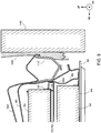
- FIG. 8 illustrates a front sectional view taken along the line A-A of FIG. 7 ; i.e., including the overlap region 74A.
- the longitudinal frame 74 of the middle frame 70 is aligned with the rear side member 112 in terms of a position in the vehicle height direction.
- a large part of the upper-stage battery stack 54 is also aligned with the rear side member 112 in terms of a position in the vehicle height direction.
- FIG. 9 illustrates a behavior during the side collision of the vehicle in a front sectional view similar to FIG. 8 .
- an obstacle is a roadside pole 140.
- the pole 140 include a telephone pole and a standing tree.
- a collision area of the pole 140 with the vehicle is smaller than that of a collision object such as a wall. Therefore, the pole 140 is easily dented inward in the vehicle width direction while the vehicle is not sufficiently slowed down.
- the battery pack 10 that is a heavy weight is energized outward in the vehicle width direction due to inertia.
- the lower-stage battery stack 52 in the battery pack 10 is fastened to the front side member 110 via the lower frame 30. Based on such a fastening structure, relative positions of the lower-stage battery stack 52 and the rear side member 112 coupled to the front side member 110 are maintained at least in an initial stage even during the side collision.
- the upper-stage battery stack 54 when the upper-stage battery stack 54 is energized outward in the vehicle width direction due to the inertia, the upper end of the support bracket 58 undergoes buckling deformation outward in the vehicle width direction from the ridgeline 58A of the support bracket 58 which is a deformation starting point. As a result, the upper-stage battery stack 54 and the middle frame 70 that supports this stack are moved outward in the vehicle width direction. That is, the upper-stage battery stack 54 comes close to the rear side member 112.
- the pole 140 enters a rear side door 130 inward in the vehicle width direction while deforming the door. Furthermore, the rear side member 112 receives the pole 140 via the rear side door 130. Consequently, the rear side member 112 comes inward in the vehicle width direction while deforming its closed sectional shape.
- the upper-stage battery stack 54 and the middle frame 70 that follow the deformation of the support bracket 58 to be moved outward in the vehicle width direction come close to the rear side member 112 pushed inward in the vehicle width direction as the pole 140 enters the member.
- the longitudinal frame 74 that projects from the upper-stage battery stack 54 outward in the vehicle width direction comes in contact with the rear side member 112 ahead of the upper-stage battery stack 54 to receive a collision load of the member.
- the longitudinal frame 74 When receiving the collision load, the longitudinal frame 74 is pushed inward in the vehicle width direction.
- the longitudinal frame 74 (and the middle frame 70) is provided in a separation space between the upper-stage battery stack 54 and the lower-stage battery stack 52.
- the upper-stage battery stack 54 and the lower-stage battery stack 52 are arranged to avoid the longitudinal frame 74 in the vehicle height direction.
- the upper-stage battery stack 54 and the lower-stage battery stack 52 are arranged to come away from a load transmission path, when the load in the vehicle width direction is input into the longitudinal frame 74.
- the middle frame 70 having the longitudinal frame 74 is provided in the separation space between the upper-stage battery stack 54 and the lower-stage battery stack 52. Consequently, transmission of the collision load to the upper-stage battery stack 54 and the lower-stage battery stack 52 during the vehicle side collision is inhibited.
- the longitudinal frame 74 projects further outward from a fastening space in which the L-shaped bracket 60 is fastened in the vehicle width direction, over the total length in the vehicle front-rear direction, but the vehicle lower structure according to the present embodiment is not limited to this configuration.
- the outward projection from this fastening space may be limited to a portion in contact with the rear side member 112.
- FIG. 10 shows a first alternative example of the vehicle lower structure according to the present embodiment. This example is different from the embodiment of FIG. 6 in comprising a middle frame 170 and an auxiliary member 180.
- the middle frame 170 comprises a longitudinal frame 174.
- a configuration of a transverse frame 72 or the like may be similar to that of the embodiment of FIG. 6 .
- a dimension of the longitudinal frame 174 in a vehicle width direction is limited to a fastening space of an L-shaped bracket 60. Furthermore, there are provided auxiliary members 180 that project outward from a pair of longitudinal frames 174, 174 in the vehicle width direction via support brackets 58.
- Each auxiliary member 180 may be, for example, a square steel tube in the same manner as in the longitudinal frame 174. Additionally, the auxiliary member 180 is configured to project further outward from the overlap region 74A of the longitudinal frame 74 and the rear side member 112 shown in FIG. 7 in the vehicle width direction, in the longitudinal frame 174. For example, the auxiliary member 180 has a length that is about 1/3 of a total length of the longitudinal frame 174 in a vehicle front-rear direction, and is disposed ahead of the longitudinal frame 174.
- a member that projects outward in the vehicle width direction (the auxiliary member 180) is provided only in the overlap region 74A. Consequently, as compared with a case where the longitudinal frame 174 projects outward to a region that does not overlap with a rear side member 112 in the vehicle width direction, a volume of the middle frame 170 can be effectively decreased.
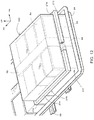
- FIG. 11 shows a second alternative example of the vehicle lower structure according to the present embodiment. This example is different from the embodiment of FIG. 6 in that an upper-stage battery stack 54 and an upper-stage center tunnel 55 are supported only by a pair of support brackets 258, 258. Furthermore, the example of FIG. 11 is different from the embodiment of FIG.
- a square frame-shaped middle frame 270 is arranged at a height position that matches a height position of a separation space between the upper-stage battery stack 54 coupled to the upper-stage center tunnel 55 and the lower-stage battery stack 52 coupled to the lower-stage center tunnel 53 in the vehicle height direction.
- the pair of support brackets 258, 258 are, for example, plate-shaped support members that extend upward from an upper surface 24B (see FIG. 4 ) of a case tray 24 in a vehicle front-rear direction.
- each support bracket 258 extends over a total length of upper-stage battery stacks 54 arranged in three rows in the vehicle front-rear direction.
- Upper portions of inner surfaces of the pair of support brackets 258, 258 in a vehicle width direction abut on and are fastened to outer surfaces of the upper-stage battery stack 54 in the vehicle width direction. Furthermore, an inner surface of the upper-stage battery stack 54 in the vehicle width direction abuts on and is fastened to a side surface of the upper-stage center tunnel 55. That is, the upper-stage battery stack 54 and the upper-stage center tunnel 55 are fastened to each other in the vehicle width direction.
- the upper-stage battery stack 54 and the upper-stage center tunnel 55 are separated from the lower-stage battery stack 52 and the lower-stage center tunnel 53 in the vehicle height direction.
- the square frame-shaped middle frame 270 is provided to match, in height, the separation space in the vehicle height direction, and to surround the separation space.
- the middle frame 270 comprises a transverse frame 272 and a longitudinal frame 274.
- a pair of the transverse frames 272 each extending in the vehicle width direction are provided in the vehicle front-rear direction.
- the longitudinal frames 274 extend in the vehicle front-rear direction and are connected to both ends of the pair of transverse frames 272, 272 in the vehicle width direction.
- the longitudinal frame 274 projects outward from the upper-stage battery stack 54 in the vehicle width direction.
- the longitudinal frame 274 of the middle frame 270 comes in contact with a rear side member 112 ahead of the upper-stage battery stack 54 to receive a collision load. Furthermore, the upper-stage battery stack 54 and the lower-stage battery stack 52 are provided to avoid the middle frame 270 in the vehicle height direction. Consequently, transmission of a collision load received by the middle frame 270 to the upper-stage battery stack 54 and the lower-stage battery stack 52 is inhibited, and the collision load is transmitted mainly to the transverse frame 272.
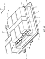
- FIG. 12 shows still another example different from FIG. 6 , FIG. 10 , and FIG. 11 .
- any support brackets are not provided, and an upper-stage battery stack 54 is stacked onto a lower-stage battery stack 52.
- the lower-stage battery stack 52 and a lower-stage center tunnel 53 are stored in a lower-stage case 310.
- the lower-stage case 310 is fastened to a lower frame 30 via an unshown bracket or the like.
- the lower-stage case 310 is, for example, a housing made of a resin.
- a top wall (an upper wall) of the case is separated vertically from upper surfaces of the lower-stage battery stack 52 and the lower-stage center tunnel 53 in a vehicle height direction. In other words, a space is provided between each of the upper surfaces of the lower-stage battery stack 52 and the lower-stage center tunnel 53 and the top wall of the lower-stage case 310.
- the upper-stage battery stack 54 and an upper-stage center tunnel 55 are stored in an upper-stage case 300.
- the upper-stage case 300 is, for example, a housing made of a resin, and is disposed directly on the lower-stage case 310.
- the upper-stage case 300 and the lower-stage case 310 are fixed to each other, for example, with screws, fitting, a band, or the like.
- a separation space is defined to separate, in the vehicle height direction, the lower-stage battery stack 52 from the upper-stage battery stack 54 via the lower-stage case 310 and the upper-stage case 300.
- a middle frame 270 is provided to match, in height, the separation space in the vehicle height direction, and to surround the separation space.
- the middle frame 270 is similar to the middle frame 270 illustrated in FIG. 11 , and a longitudinal frame 274 projects outward from the upper-stage case 300 in a vehicle width direction.
- the longitudinal frame 274 of the middle frame 270 comes in contact with a rear side member 112 ahead of the upper-stage battery stack 54 to receive a collision load.
- the upper-stage battery stack 54 and the lower-stage battery stack 52 are provided to avoid the middle frame 270 in the vehicle height direction. Consequently, transmission of the collision load received by the middle frame 270 to the upper-stage battery stack 54 and the lower-stage battery stack 52 is inhibited, and the collision load is transmitted mainly to a transverse frame 272.
Landscapes
- Engineering & Computer Science (AREA)
- Transportation (AREA)
- Mechanical Engineering (AREA)
- Chemical & Material Sciences (AREA)
- Combustion & Propulsion (AREA)
- Sustainable Energy (AREA)
- Power Engineering (AREA)
- Life Sciences & Earth Sciences (AREA)
- Sustainable Development (AREA)
- Aviation & Aerospace Engineering (AREA)
- Chemical Kinetics & Catalysis (AREA)
- Electrochemistry (AREA)
- General Chemical & Material Sciences (AREA)
- Arrangement Or Mounting Of Propulsion Units For Vehicles (AREA)
- Body Structure For Vehicles (AREA)
Abstract
Description
- This application claims priority to Japanese Patent Application No.
2019-001664, filed on January 9, 2019 - The present disclosure relates to a vehicle lower structure in which a battery is stored under a floor of a vehicle.
- In a vehicle, such as an electric car, in which a rotating electric machine is used as a driving source, a battery is mounted as a power source for the vehicle. For example, in the publication of
JP 2010-153130 A - The battery pack, which is a heavy weight, is fixed to a framework member of the vehicle. For example, a lower frame that is the framework member is provided on a bottom surface of the battery pack, and the lower frame projects outward from the battery pack in a vehicle width direction. Meanwhile, a pair of side members that are the framework members are provided on both sides of the floor panel in the vehicle width direction and extend in a vehicle front-rear direction. Portions of the lower frame that project from the battery pack are fastened to the side members with nuts and bolts or the like.
- A plurality of battery stacks are stored in the battery pack. In this storage, arrangement of the battery stacks is determined to follow a floor shape of the vehicle. For example, a floor surface of a luggage space behind the vehicle chamber is raised above a floor surface of a passenger space. In a rear portion of the battery pack disposed along this floor surface shape under a floor, the battery stacks are stacked in two stages, upper and lower.
- To acquire a space of a cooling air flow path and a conduction wire (a cable) in the lower-stage battery stack, the upper-stage battery stack is separated from the lower-stage battery stack in a vehicle height direction. For example, a bracket that is a support member extends from a bottom surface of a case tray that stores the battery stack in a vehicle height direction, and the upper-stage battery stack is supported (raised and supported) by the bracket.
- Additionally, when the lower frame of the bottom surface of the battery pack is fastened to the pair of side members, the battery pack is disposed between the pair of side members. At this time, a position of at least a part of the battery pack matches a position of each side member in a vehicle height direction.
- When collision of a side surface of the vehicle (hereinafter appropriately referred to as side collision) occurs in such an arrangement as described above, the battery pack that is the heavy weight is energized in the vehicle width direction due to inertia (laterally shaken). At this time, there is concern that the upper-stage battery stack comes in contact with the side member that is present on a side of the battery stack.
- That is, the lower-stage battery stack is fixed to a lower arm, and the lower arm is fixed to the side member. Therefore, there is structurally low possibility that the lower-stage battery stack comes in contact with the side member. On the other hand, the upper-stage battery stack is fixed to the lower arm via a support member such as the bracket in a state where the battery stack is separated (floated) from the lower-stage battery stack. When the upper-stage battery stack is energized in the vehicle width direction during the side collision, the bracket undergoes buckling deformation, depending on a strength of the bracket. Consequently, there is concern that the upper-stage battery stack moves in the vehicle width direction to be in contact with the side member as it is.
- It is considered that to inhibit the buckling deformation of the bracket, the strength of the bracket (the support member) is increased, for example, by use of a steel plate having a large thickness. However, for example, there is concern that change in thickness also causes increase in weight of the upper-stage battery pack, and a complicated operation of calculating the strength again to change the thickness is required to cope with such change in design.
- To solve the problem, it is an advantage of the present disclosure to provide a vehicle lower structure in which it is possible to inhibit transmission of a collision load to an upper-stage battery stack during side collision irrespective of a strength of a support member of the upper-stage battery stack.
- The present disclosure relates to a vehicle lower structure. The structure comprises a battery pack, a lower frame, and a pair of side frames. The battery pack is stored under a floor panel. The lower frame is a framework member provided on a bottom surface of the battery pack, and having fastening portions formed at both ends that project outward from the battery pack in a vehicle width direction. A pair of side members are framework members that are provided on both sides of the floor panel in the vehicle width direction and extend in a vehicle front-rear direction, and to which the fastening portions of the lower frame are fastened. The battery pack comprises a lower-stage battery stack fixed to the lower frame, and an upper-stage battery stack mounted in an upper stage of the lower-stage battery stack. The upper-stage battery stack is separated from the lower-stage battery stack in a vehicle height direction. Furthermore, a reinforcing member is arranged at a height position that matches a height position of a separation space between the upper-stage battery stack and the lower-stage battery stack in the vehicle height direction. The reinforcing member comprises a pair of transverse frames extending in the vehicle width direction and provided in the vehicle front-rear direction, and a pair of longitudinal frames connected to both ends of the pair of transverse frames in the vehicle width direction and extending in the vehicle front-rear direction, and the longitudinal frames project outward from the upper-stage battery stack in the vehicle width direction.
- According to the above configuration, the longitudinal frames of the reinforcing member project outward from the upper-stage battery stack in the vehicle width direction, and therefore come in contact with the side members ahead of the upper-stage battery stack during side collision. Furthermore, the longitudinal frames are provided so that they match, in height, the separation space between the upper-stage battery stack and the lower-stage battery stack in the vehicle height direction, and the upper-stage battery stack and the lower-stage battery stack are arranged to avoid the longitudinal frames in the vehicle height direction. Therefore, loads received by the longitudinal frames in the vehicle width direction are transmitted to the transverse frames, while the loads are inhibited from being transmitted to the upper-stage battery stack and the lower-stage battery stack.
- Furthermore, in the above disclosure, each longitudinal frame may include an overlap region that is aligned with the side member in terms of a position in the vehicle height direction. In this case, an auxiliary member may be provided to project further outward from the overlap region of the longitudinal frame in the vehicle width direction.
- A projection width in the vehicle width direction is expanded by the auxiliary member, thereby avoiding proximity of each side member to the upper-stage battery stack. Furthermore, the auxiliary member is provided only in the overlap region. Consequently, increase in weight of the member may be suppressed, as compared with, for example, a case where the auxiliary member is provided over an entire length of the longitudinal frame in a longitudinal direction.
- Furthermore, in the above disclosure, the battery pack may comprise a case tray that stores the upper-stage battery stack and the lower-stage battery stack. In this case, the upper-stage battery stack is fixed to an upper end of a plate-shaped bracket extending upward from the case tray in the vehicle front-rear direction. Furthermore, a ridgeline is formed on the bracket across the vehicle front-rear direction.
- The ridgeline is provided across the vehicle front-rear direction. Consequently, rigidity of the bracket in the vehicle front-rear direction improves. On the other hand, there is concern that the ridgeline across the vehicle front-rear direction becomes a starting point of buckling deformation of the bracket during side collision. However, even in case of the buckling deformation, the auxiliary member collides with the side members ahead of the upper-stage battery stack as described above. Consequently, transmission of a collision load to the upper-stage battery stack is inhibited.
- According to the present disclosure, it is possible to inhibit the transmission of the collision load to the upper-stage battery stack during the side collision, irrespective of a strength of the support member of the battery stack of the upper stage.
- Embodiments of the present disclosure will be described based on the following figures, wherein:
-
FIG. 1 is an exploded perspective view illustrating a vehicle lower structure according to the present embodiment; -
FIG. 2 is a perspective view illustrating a bottom surface structure of a battery pack; -
FIG. 3 is an exploded perspective view explaining a fastening example of the battery pack to side members; -
FIG. 4 is an exploded perspective view illustrating constituting members of the battery pack; -
FIG. 5 is a perspective view showing an example where a middle frame is fastened to a support bracket; -
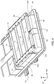
FIG. 6 is a perspective view showing an example where an upper-stage battery stack and an upper-stage center tunnel are arranged on the middle frame; -
FIG. 7 is a side view illustrating a positional relation between the battery pack and a rear side member; -
FIG. 8 is a sectional view taken along the line A-A ofFIG. 7 ; -
FIG. 9 is a sectional view taken along the line A-A and showing a behavior during side collision with a pole; -
FIG. 10 is a perspective view showing a first alternative example of the vehicle lower structure according to the present embodiment, and showing an example where an auxiliary member is attached to a side of a longitudinal frame; -
FIG. 11 is a perspective view showing a second alternative example of the vehicle lower structure according to the present embodiment; and -
FIG. 12 is a perspective view showing a third alternative example of the vehicle lower structure according to the present embodiment. -
FIG. 1 to FIG. 12 illustrate a vehicle lower structure according to an embodiment of the present invention. Note that inFIG. 1 to FIG. 12 , a vehicle front-rear direction is shown by an axis denoted with symbol FR, a vehicle width direction is shown by an axis denoted with symbol RW, and a vehicle up-down direction is shown by an axis denoted with symbol UP. Along the vehicle front-rear axis FR, a vehicle front direction is a forward direction. Along the vehicle width axis RW, a right width direction is a forward direction. Furthermore, along the vehicle up-down axis UP, an up direction is a forward direction. These three axes are orthogonal to one another. -
FIG. 1 illustrates an exploded perspective view of the vehicle lower structure according to the present embodiment. The vehicle lower structure according to the present embodiment is mounted in, for example, an electric car. The vehicle lower structure comprises abattery pack 10, alower frame 30, afront side member 110, and arear side member 112. -
FIG. 1 illustrates thebattery pack 10 and framework members of a vehicle which support this battery pack, and secondarily shows a panel member andrear tires 118 by broken lines. The framework members of the vehicle comprise a pair of thefront side members rear side members rockers floor cross member 113 and arear cross member 114 as "transverse frames" extending in the vehicle width direction. Each of these members is constituted of, for example, a high-tensile steel plate or a hot stamp steel plate. - Both the pair of
front side members 110 and the pair ofrear side members 112 are framework members provided on both sides of a floor panel 120 (seeFIG. 3 ) in the vehicle width direction and extending in the vehicle front-rear direction. Thefront side members 110 and therear side members 112 may be grasped together as pairs of side members extending in the vehicle front-rear direction. - For example, the pair of
front side members floor cross member 113 in the vehicle chamber. Furthermore, referring toFIG. 3 ,fastening portions 36 of thelower frame 30 are fastened to thefront side members - For example, each of the
front side members upper member 110A that is an upper member and a front sidelower member 110B that is a lower member. Each of the front sideupper member 110A and the front sidelower member 110B has a hat-shaped section, and the two members are superimposed onto each other to constitute a closed section. - Referring to
FIG. 1 , front ends of the pair ofrear side members front side members rear side members floor cross member 113 to a rear bumper reinforcement (not shown) at a vehicle rear end. - As shown in
FIG. 1 orFIG. 7 , each of therear side members horizontal portion 112A, a kick-upportion 112B, and a rearhorizontal portion 112C from a front end of the member. The kick-upportion 112B is provided between the fronthorizontal portion 112A and the rearhorizontal portion 112C, and has an inclined shape obliquely extending upward toward a rear of the vehicle. Arear suspension member 122 is fastened to the rearhorizontal portion 112C. Therear suspension member 122 supports a rear suspension mechanism from which the rear tire 118 (seeFIG. 1 ) is suspended. - Furthermore, as illustrated in
FIG. 8 , therear side member 112 has a hat-shaped section, and has an open end that is covered with thefloor panel 120 to constitute a closed section. -
FIG. 2 illustrates a bottom surface perspective view of acase tray 24 of thebattery pack 10. Abottom surface 24A of thecase tray 24 is provided with a plurality of thelower frames 30 that are the framework members. Eachlower frame 30 extends in the vehicle width direction, and the respective lower frames are arranged via a space in the vehicle front-rear direction. - Additionally, a plurality of
lower members 34 that are framework members are provided in the vehicle front-rear direction via a space in the vehicle width direction to straddle the respectivelower frames lower frames 30 and the lower members 34) is constituted of, for example, a high-tensile steel plate or a hot stamp steel plate. - The lower frames 30 excluding, for example, a rearmost end
lower frame 30 are configured so that both ends of each lower frame project outward from thebattery pack 10; i.e., thecase tray 24, in the vehicle width direction. Such both projecting end portions become thefastening portions 36. Fastening holes 32 are made to extend through thefastening portions 36 in a thickness direction. - As illustrated in
FIG. 3 , thefastening portions 36 of thelower frame 30 are fastened to thefront side members bolts 38 are screwed into the fastening holes 32 of thefastening portions 36 of thelower frame 30. Furthermore, eachbolt 38 is screwed into aweld nut 111 provided in the front sidelower member 110B through acollar 40. The bolts are screwed into all the fastening holes 32 in this way. Consequently, thelower frame 30 and thebattery pack 10 supported by this lower frame are fastened to thefront side members - Referring to
FIG. 1 again, a pair ofrear brackets battery pack 10. Lower ends of therear brackets case tray 24 of acase 20. Furthermore, upper ends of therear brackets rear cross member 114. Thus, when thebattery pack 10 is stored under thefloor panel 120, thebattery pack 10 is fastened to thefront side members lower frame 30, and is also fastened to therear cross member 114 via therear brackets -
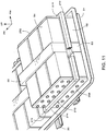
FIG. 1 illustrates the whole perspective view of thebattery pack 10. Furthermore,FIG. 4 illustrates respective members stored in thecase 20 in an exploded perspective view. Note thatFIG. 4 omits drawing of acase cover 22. Thebattery pack 10 comprises thecase 20, a lower-stage battery stack 52, a lower-stage center tunnel 53, an upper-stage battery stack 54, an upper-stage center tunnel 55, asupport bracket 58, abattery ECU 59, and amiddle frame 70. - Note that the lower-
stage battery stack 52 and the upper-stage battery stack 54 are different in that each is disposed in the upper stage or the lower stage, but they have an equal (common) basic structure. Furthermore, the lower-stage battery stack 52 and the upper-stage battery stack 54 are different in that, for example, a number of battery cells 51 (seeFIG. 3 ) stored in each stack of the upper stage is smaller than that of the battery cells stored in the stack of the lower stage, but each stack is provided with a reinforcing structure, a wire, or equipment such as a temperature sensor or a current sensor. - The
case 20 stores the lower-stage battery stack 52, the upper-stage battery stack 54, themiddle frame 70, and others, and comprises thecase cover 22 and thecase tray 24 that are upper members. Referring toFIG. 1 , a shape of the case cover 22 is determined in accordance with arrangement of members to be stored in thecase 20. For example, referring toFIG. 4 andFIG. 6 , the upper-stage battery stack 54 is brought to and disposed in a rear of thecase 20. Consequently, a rear of the case cover 22 has a shape that bulges further upward than does a front of the case cover. - The
case tray 24 has a boat shape, and on thebottom surface 24A (seeFIG. 2 ) of the case tray, thelower frame 30 and thelower members 34 described above are provided. Referring toFIG. 4 , anupper surface 24B (a case inner surface) of thecase tray 24 is in a form of a flat plate, and on theupper surface 24B, there are stored thebattery ECU 59, the lower-stage battery stack 52, the lower-stage center tunnel 53, the upper-stage battery stack 54, the upper-stage center tunnel 55, themiddle frame 70, and others. - The
battery ECU 59 manages charging/discharging of the lower-stage battery stack 52 and the upper-stage battery stack 54, and manages temperatures of these stacks. For example, thebattery ECU 59 is an electronic control unit constituted of a computer. Thebattery ECU 59 is disposed in a front end portion of thecase 20 in the vehicle front-rear direction, and is connected to a power control unit (not shown) such as a DC/DC converter or an inverter provided in the front compartment (not shown), via a high-voltage cable or the like. - Furthermore, a plurality of the lower-stage battery stacks 52 are arranged in the
case tray 24. For example, the plurality of lower-stage battery stacks 52 are arranged in the vehicle front-rear direction, via the lower-stage center tunnel 53 disposed at a center in the vehicle width direction. A plurality of battery cells 51 (seeFIG. 3 ) are stored in the respective lower-stage battery stacks 52. - Furthermore, each of the lower-stage battery stacks 52 is fixed (fastened) to the
lower frame 30 via an unshown bracket or the like in the case. Consequently, for example, during side collision of the vehicle, there is maintained a state where the lower-stage battery stack 52 is supported by and fixed to thelower frame 30. - The lower-
stage center tunnel 53 is provided between the lower-stage battery stacks 52, 52 arranged side by side in the vehicle width direction. For example, the lower-stage center tunnel 53 extends from a rear end of thebattery ECU 59 to a rear end of thecase tray 24 in the vehicle front-rear direction. For example, a high-voltage cable 56 (seeFIG. 3 ) is disposed (routed) in the lower-stage center tunnel 53. - The upper-stage battery stacks 54 are mounted on the rear lower-stage battery stacks 52 among the plurality of lower-stage battery stacks 52. For example, when the lower-stage battery stacks 52 are arranged in eight rows in the vehicle front-rear direction, the upper-stage battery stacks 54 are mounted on three rear rows of the lower-stage battery stacks 52.
- Here, if both the stacks are directly stacked so that a bottom surface of the upper-
stage battery stack 54 is located on a top surface of the lower-stage battery stack 52, there is concern that heat generated by the lower-stage battery stack 52 encounters difficulty escaping to the outside. To solve the problem, for example, a heat dissipating space is provided, or a space is provided as a flow path of cooling air above the lower-stage battery stack 52. - Thus, when the upper-
stage battery stack 54 is separated from and stacked above the lower-stage battery stack 52 in the vehicle height direction, thesupport bracket 58 and themiddle frame 70 are provided. - Referring to
FIG. 4 andFIG. 5 , thesupport bracket 58 is a plate-shaped support metal fitting that extends upward from theupper surface 24B (a case inner surface) of thecase tray 24 in the vehicle front-rear direction. Thesupport bracket 58 may extend, for example, over a total length of three rows of upper-stage battery stacks 54 arranged in the vehicle front-rear direction, but may extend, for example, along a length of about two rows, which is shorter than the total length. Consequently, for example, a side of the lower-stage battery stack 52 in the vehicle width direction is opened in a rearmost row in the vehicle front-rear direction. Consequently, a heat dissipation path is acquired in the corresponding region. - A height of the support bracket 58 (a length in the vehicle height direction) is determined so that a space is provided between the
middle frame 70 and the lower-stage battery stack 52. For example, a value obtained by adding a predetermined margin (a space height) to a height of the lower-stage battery stack 52 and a thickness of themiddle frame 70 is determined as the height of thesupport bracket 58. - Furthermore, as illustrated in
FIG. 5 , aridgeline 58A is formed on thesupport bracket 58 across the vehicle front-rear direction. For example, thesupport bracket 58 is provided with a bent portion obtained by forming a step in a flat plate, and theridgeline 58A is formed as a folded line of the bent portion in the vehicle front-rear direction. - Thus, the
ridgeline 58A is formed in the vehicle front-rear direction, so that load bearing properties of thesupport bracket 58 in the vehicle front-rear direction improve. For example, the upper-stage battery stack 54 on themiddle frame 70 is energized rearward or forward at sudden start or sudden stop, but thesupport bracket 58 may support the upper-stage battery stack 54 against such energization in the vehicle front-rear direction. - On the other hand, the
support bracket 58 easily causes buckling deformation from a start point of theridgeline 58A due to the energization in the vehicle width direction, for example, during side collision of the vehicle or the like. However, alongitudinal frame 74 of themiddle frame 70 comes in contact with therear side member 112 ahead of the upper-stage battery stack 54 as described later. Consequently, transmission of a collision load to the upper-stage battery stack 54 is inhibited. - A pair of the
support brackets 58 are arranged in a gap provided betweenside walls case tray 24 in the vehicle width direction and the lower-stage battery stack 52. A lower end of thesupport bracket 58 is fastened to, for example, thelower frame 30. - Furthermore, the upper-
stage battery stack 54 and the upper-stage center tunnel 55 are fixed to upper ends of the pair ofsupport brackets middle frame 70. That is, themiddle frame 70 is fastened and held between the upper ends of the pair ofsupport brackets stage center tunnel 55 are arranged on themiddle frame 70. - Additionally, the lower-stage battery stacks 52 are provided under the
middle frame 70. Based on such arrangement, in particular,transverse frames 72 andlongitudinal frames 74 of themiddle frame 70 may be grasped as reinforcing members provided so that their vehicle height positions are aligned with a spaced region from the lower-stage battery stack 52 and the upper-stage battery stack 54. - The
middle frame 70 comprises thetransverse frame 72, thelongitudinal frame 74, and aplate 76. A plurality oftransverse frames 72 extending in the vehicle width direction are arranged via a space in the vehicle front-rear direction. For example, in an example shown inFIG. 5 , fourtransverse frames 72 are provided. As shown in a partially sectional view ofFIG. 5 , for example, eachtransverse frame 72 is constituted of a square steel pipe. As described later, thetransverse frame 72 is constituted of a high-tensile steel material to resist the collision load from therear side member 112 during the side collision of the vehicle. - The
plate 76 is provided between the adjacenttransverse frames plate 76 is constituted of a metal plate such as an iron plate or an aluminum plate. For example, from a viewpoint of promoting the heat dissipation from the bottom surface of the upper-stage battery stack 54, theplate 76 may be omitted. - A pair of the
longitudinal frames 74 are provided at both ends of themiddle frame 70 in the vehicle width direction. Thelongitudinal frames 74 are frame members extending in the vehicle front-rear direction, and are connected to both ends of each of pairs oftransverse frames middle frame 70 in the vehicle front-rear direction. For example, as illustrated inFIG. 5 , eachlongitudinal frame 74 is constituted of a square steel pipe. Furthermore, thelongitudinal frame 74 is constituted of, for example, a high-tensile steel material in the same manner as in thetransverse frame 72. - For example, an upper surface of the
longitudinal frame 74 is formed in a stepped shape in which an inner side in the vehicle width direction is recessed relative to an outer side. This stepped shape is utilized in positioning the upper-stage battery stack 54 when mounting the stack. - Furthermore, as illustrated in
FIG. 6 , a pair of thelongitudinal frames stage battery stack 54 in the vehicle width direction. For example, in the above stepped shape, a surface that corresponds to an upper step of the stepped portion projects outward from the upper-stage battery stack 54 in the vehicle width direction. - The
longitudinal frame 74 projects outward from the upper-stage battery stack 54 in the vehicle width direction. Consequently, as described later, thelongitudinal frame 74 comes in contact with therear side member 112 to receive the collision load ahead of the upper-stage battery stack 54 during the side collision of the vehicle. In consequence, transmission of the collision load to the upper-stage battery stack 54 is inhibited. - Note that as illustrated in
FIG. 8 , in a spatial relation between thecase 20 and each surrounding vehicle part, an outer surface of the lower-stage battery stack 52 in the vehicle width direction is positioned in the vehicle width direction to substantially coincide with an outer surface of thelongitudinal frame 74 in the vehicle width direction. Consequently, the upper-stage battery stack 54 is configured so that a number of the battery cells 51 (seeFIG. 3 ) to be stacked per upper-stage battery stack is smaller than that per lower-stage battery stack 52. - Referring to
FIG. 6 , the upper-stage battery stack 54 is fastened to themiddle frame 70 via an L-shapedbracket 60. The L-shapedbracket 60 is an L-shaped fixing metal fitting in front view, in which one piece that constitutes an L-shape abuts on an outer surface of the upper-stage battery stack 54 in the vehicle width direction, while the other piece abuts on the upper surface of thelongitudinal frame 74. -
FIG. 7 illustrates a side view showing a positional relation between therear side member 112 and thebattery pack 10. Themiddle frame 70 and the upper-stage battery stack 54 have a positional relation of being partially aligned with the kick-upportion 112B of therear side member 112 in the vehicle height direction. For example, all the three rows of upper-stage battery stacks 54 arranged in the vehicle front-rear direction are partially aligned with the kick-upportion 112B in terms of a position in the vehicle height direction. Furthermore, themiddle frame 70 and thelongitudinal frame 74 are aligned with the kick-upportion 112B in terms of a position in the vehicle height direction in a front part; i.e., in anoverlap region 74A hatched inFIG. 7 . -
FIG. 8 illustrates a front sectional view taken along the line A-A ofFIG. 7 ; i.e., including theoverlap region 74A. As illustrated in this drawing, thelongitudinal frame 74 of themiddle frame 70 is aligned with therear side member 112 in terms of a position in the vehicle height direction. Furthermore, a large part of the upper-stage battery stack 54 is also aligned with therear side member 112 in terms of a position in the vehicle height direction. -
FIG. 9 illustrates a behavior during the side collision of the vehicle in a front sectional view similar toFIG. 8 . For example, an obstacle is aroadside pole 140. Examples of thepole 140 include a telephone pole and a standing tree. For example, a collision area of thepole 140 with the vehicle is smaller than that of a collision object such as a wall. Therefore, thepole 140 is easily dented inward in the vehicle width direction while the vehicle is not sufficiently slowed down. - Referring to
FIG. 9 , when a side surface of the vehicle collides with thepole 140, thebattery pack 10 that is a heavy weight is energized outward in the vehicle width direction due to inertia. Here, the lower-stage battery stack 52 in thebattery pack 10 is fastened to thefront side member 110 via thelower frame 30. Based on such a fastening structure, relative positions of the lower-stage battery stack 52 and therear side member 112 coupled to thefront side member 110 are maintained at least in an initial stage even during the side collision. - On the other hand, when the upper-
stage battery stack 54 is energized outward in the vehicle width direction due to the inertia, the upper end of thesupport bracket 58 undergoes buckling deformation outward in the vehicle width direction from theridgeline 58A of thesupport bracket 58 which is a deformation starting point. As a result, the upper-stage battery stack 54 and themiddle frame 70 that supports this stack are moved outward in the vehicle width direction. That is, the upper-stage battery stack 54 comes close to therear side member 112. - When a side collision process proceeds, the
pole 140 enters arear side door 130 inward in the vehicle width direction while deforming the door. Furthermore, therear side member 112 receives thepole 140 via therear side door 130. Consequently, therear side member 112 comes inward in the vehicle width direction while deforming its closed sectional shape. - Thus, the upper-
stage battery stack 54 and themiddle frame 70 that follow the deformation of thesupport bracket 58 to be moved outward in the vehicle width direction come close to therear side member 112 pushed inward in the vehicle width direction as thepole 140 enters the member. At this time, thelongitudinal frame 74 that projects from the upper-stage battery stack 54 outward in the vehicle width direction comes in contact with therear side member 112 ahead of the upper-stage battery stack 54 to receive a collision load of the member. - When receiving the collision load, the
longitudinal frame 74 is pushed inward in the vehicle width direction. Here, the longitudinal frame 74 (and the middle frame 70) is provided in a separation space between the upper-stage battery stack 54 and the lower-stage battery stack 52. The upper-stage battery stack 54 and the lower-stage battery stack 52 are arranged to avoid thelongitudinal frame 74 in the vehicle height direction. In other words, the upper-stage battery stack 54 and the lower-stage battery stack 52 are arranged to come away from a load transmission path, when the load in the vehicle width direction is input into thelongitudinal frame 74. Therefore, even when thelongitudinal frame 74 is pushed inward in the vehicle width direction, transmission of the collision load to the upper-stage battery stack 54 and the lower-stage battery stack 52 is inhibited, and the collision load is transmitted mainly to thetransverse frame 72. Furthermore, thelongitudinal frame 74 is inhibited from being pushed inward in the vehicle width direction because thetransverse frame 72 stretches. - Consequently, in the present embodiment, the
middle frame 70 having thelongitudinal frame 74 is provided in the separation space between the upper-stage battery stack 54 and the lower-stage battery stack 52. Consequently, transmission of the collision load to the upper-stage battery stack 54 and the lower-stage battery stack 52 during the vehicle side collision is inhibited. - Note that in the example of
FIG. 6 , thelongitudinal frame 74 projects further outward from a fastening space in which the L-shapedbracket 60 is fastened in the vehicle width direction, over the total length in the vehicle front-rear direction, but the vehicle lower structure according to the present embodiment is not limited to this configuration. For example, the outward projection from this fastening space may be limited to a portion in contact with therear side member 112. -
FIG. 10 shows a first alternative example of the vehicle lower structure according to the present embodiment. This example is different from the embodiment ofFIG. 6 in comprising amiddle frame 170 and anauxiliary member 180. Themiddle frame 170 comprises alongitudinal frame 174. Note that a configuration of atransverse frame 72 or the like may be similar to that of the embodiment ofFIG. 6 . - A dimension of the
longitudinal frame 174 in a vehicle width direction is limited to a fastening space of an L-shapedbracket 60. Furthermore, there are providedauxiliary members 180 that project outward from a pair oflongitudinal frames support brackets 58. - Each
auxiliary member 180 may be, for example, a square steel tube in the same manner as in thelongitudinal frame 174. Additionally, theauxiliary member 180 is configured to project further outward from theoverlap region 74A of thelongitudinal frame 74 and therear side member 112 shown inFIG. 7 in the vehicle width direction, in thelongitudinal frame 174. For example, theauxiliary member 180 has a length that is about 1/3 of a total length of thelongitudinal frame 174 in a vehicle front-rear direction, and is disposed ahead of thelongitudinal frame 174. - Thus, a member that projects outward in the vehicle width direction (the auxiliary member 180) is provided only in the
overlap region 74A. Consequently, as compared with a case where thelongitudinal frame 174 projects outward to a region that does not overlap with arear side member 112 in the vehicle width direction, a volume of themiddle frame 170 can be effectively decreased. - In each of the examples of
FIG. 6 andFIG. 10 , the upper-stage battery stack 54 and the upper-stage center tunnel 55 are arranged in themiddle frame FIG. 11 shows a second alternative example of the vehicle lower structure according to the present embodiment. This example is different from the embodiment ofFIG. 6 in that an upper-stage battery stack 54 and an upper-stage center tunnel 55 are supported only by a pair ofsupport brackets FIG. 11 is different from the embodiment ofFIG. 6 in that a square frame-shapedmiddle frame 270 is arranged at a height position that matches a height position of a separation space between the upper-stage battery stack 54 coupled to the upper-stage center tunnel 55 and the lower-stage battery stack 52 coupled to the lower-stage center tunnel 53 in the vehicle height direction. - The pair of
support brackets upper surface 24B (seeFIG. 4 ) of acase tray 24 in a vehicle front-rear direction. For example, eachsupport bracket 258 extends over a total length of upper-stage battery stacks 54 arranged in three rows in the vehicle front-rear direction. - Upper portions of inner surfaces of the pair of
support brackets stage battery stack 54 in the vehicle width direction. Furthermore, an inner surface of the upper-stage battery stack 54 in the vehicle width direction abuts on and is fastened to a side surface of the upper-stage center tunnel 55. That is, the upper-stage battery stack 54 and the upper-stage center tunnel 55 are fastened to each other in the vehicle width direction. - In such a configuration, the upper-
stage battery stack 54 and the upper-stage center tunnel 55 are separated from the lower-stage battery stack 52 and the lower-stage center tunnel 53 in the vehicle height direction. The square frame-shapedmiddle frame 270 is provided to match, in height, the separation space in the vehicle height direction, and to surround the separation space. - The
middle frame 270 comprises atransverse frame 272 and alongitudinal frame 274. A pair of thetransverse frames 272 each extending in the vehicle width direction are provided in the vehicle front-rear direction. Thelongitudinal frames 274 extend in the vehicle front-rear direction and are connected to both ends of the pair oftransverse frames longitudinal frame 274 projects outward from the upper-stage battery stack 54 in the vehicle width direction. - Also in this configuration, during side collision of a vehicle, the
longitudinal frame 274 of themiddle frame 270 comes in contact with arear side member 112 ahead of the upper-stage battery stack 54 to receive a collision load. Furthermore, the upper-stage battery stack 54 and the lower-stage battery stack 52 are provided to avoid themiddle frame 270 in the vehicle height direction. Consequently, transmission of a collision load received by themiddle frame 270 to the upper-stage battery stack 54 and the lower-stage battery stack 52 is inhibited, and the collision load is transmitted mainly to thetransverse frame 272. -
FIG. 12 shows still another example different fromFIG. 6 ,FIG. 10 , andFIG. 11 . InFIG. 11 , any support brackets are not provided, and an upper-stage battery stack 54 is stacked onto a lower-stage battery stack 52. - In the example illustrated in
FIG. 12 , the lower-stage battery stack 52 and a lower-stage center tunnel 53 are stored in a lower-stage case 310. The lower-stage case 310 is fastened to alower frame 30 via an unshown bracket or the like. - The lower-
stage case 310 is, for example, a housing made of a resin. A top wall (an upper wall) of the case is separated vertically from upper surfaces of the lower-stage battery stack 52 and the lower-stage center tunnel 53 in a vehicle height direction. In other words, a space is provided between each of the upper surfaces of the lower-stage battery stack 52 and the lower-stage center tunnel 53 and the top wall of the lower-stage case 310. - The upper-
stage battery stack 54 and an upper-stage center tunnel 55 are stored in an upper-stage case 300. The upper-stage case 300 is, for example, a housing made of a resin, and is disposed directly on the lower-stage case 310. The upper-stage case 300 and the lower-stage case 310 are fixed to each other, for example, with screws, fitting, a band, or the like. - As described above, the space is provided between each of the upper surfaces of the lower-
stage battery stack 52 and the lower-stage center tunnel 53 and the top wall of the lower-stage case 310. Therefore, a separation space is defined to separate, in the vehicle height direction, the lower-stage battery stack 52 from the upper-stage battery stack 54 via the lower-stage case 310 and the upper-stage case 300. Amiddle frame 270 is provided to match, in height, the separation space in the vehicle height direction, and to surround the separation space. - The
middle frame 270 is similar to themiddle frame 270 illustrated inFIG. 11 , and alongitudinal frame 274 projects outward from the upper-stage case 300 in a vehicle width direction. - Also in this configuration, during side collision of a vehicle, the
longitudinal frame 274 of themiddle frame 270 comes in contact with arear side member 112 ahead of the upper-stage battery stack 54 to receive a collision load. The upper-stage battery stack 54 and the lower-stage battery stack 52 are provided to avoid themiddle frame 270 in the vehicle height direction. Consequently, transmission of the collision load received by themiddle frame 270 to the upper-stage battery stack 54 and the lower-stage battery stack 52 is inhibited, and the collision load is transmitted mainly to atransverse frame 272. - The present disclosure is not limited to the present embodiments described above, and includes all changes and modifications without departing from the technical scope or the essence of the present disclosure defined by the claims.
Claims (3)
- A vehicle lower structure comprising:a battery pack (10) stored under a floor panel (120),a lower frame (30) that is a framework member provided on a bottom surface of the battery pack (10), and having fastening portions (36) formed at both ends that project outward from the battery pack (10) in a vehicle width direction,a pair of side members (110,112) that are framework members, the side members being provided on both sides of the floor panel (120) in the vehicle width direction and extending in a vehicle front-rear direction, wherein the fastening portions (36) of the lower frame (30) are fastened to the side members, whereinthe battery pack (10) comprises a lower-stage battery stack (52) fixed to the lower frame (30), and an upper-stage battery stack (54) mounted in an upper stage of the lower-stage battery stack (52),the upper-stage battery stack (54) is separated from the lower-stage battery stack (52) in a vehicle height direction,a reinforcing member (70) is arranged at a height position that matches a height position of a separation space between the upper-stage battery stack (54) and the lower-stage battery stack (52) in the vehicle height direction, andthe reinforcing member (70) comprises a pair of transverse frames (72) extending in the vehicle width direction and provided in the vehicle front-rear direction, and a pair of longitudinal frames (74) connected to both ends of the pair of transverse frames (72) in the vehicle width direction and extending in the vehicle front-rear direction, and the longitudinal frames (74) project outward from the upper-stage battery stack (54) in the vehicle width direction.
- The vehicle lower structure according to claim 1, wherein
each longitudinal frame (74) includes an overlap region (74A) that is aligned with the side members (110,112) in terms of a position in the vehicle height direction, and
an auxiliary member (180) is provided to project further outward from the overlap region (74A) of the longitudinal frame (74) in the vehicle width direction. - The vehicle lower structure according to claim 1 or 2, wherein
the battery pack (10) comprises a case tray (24) that stores the upper-stage battery stack (54) and the lower-stage battery stack (52),
the upper-stage battery stack (54) is fixed to an upper end of a plate-shaped bracket (58) extending upward from the case tray (24) in the vehicle front-rear direction, and
a ridgeline is formed on the bracket (58) across the vehicle front-rear direction.
Applications Claiming Priority (1)
| Application Number | Priority Date | Filing Date | Title |
|---|---|---|---|
| JP2019001664A JP7143768B2 (en) | 2019-01-09 | 2019-01-09 | vehicle undercarriage |
Publications (2)
| Publication Number | Publication Date |
|---|---|
| EP3690980A1 true EP3690980A1 (en) | 2020-08-05 |
| EP3690980B1 EP3690980B1 (en) | 2022-03-16 |
Family
ID=69156275
Family Applications (1)
| Application Number | Title | Priority Date | Filing Date |
|---|---|---|---|
| EP20150866.0A Active EP3690980B1 (en) | 2019-01-09 | 2020-01-09 | Vehicle lower structure |
Country Status (4)
| Country | Link |
|---|---|
| US (1) | US10967722B2 (en) |
| EP (1) | EP3690980B1 (en) |
| JP (1) | JP7143768B2 (en) |
| CN (1) | CN111422051B (en) |
Cited By (1)
| Publication number | Priority date | Publication date | Assignee | Title |
|---|---|---|---|---|
| EP3699977B1 (en) * | 2019-02-20 | 2022-01-05 | Toyota Jidosha Kabushiki Kaisha | Battery pack for vehicle |
Families Citing this family (14)
| Publication number | Priority date | Publication date | Assignee | Title |
|---|---|---|---|---|
| IT201800021199A1 (en) * | 2018-12-27 | 2020-06-27 | Ferrari Spa | ELECTRIC OR HYBRID SPORTS CAR |
| JP7339065B2 (en) * | 2019-08-21 | 2023-09-05 | マツダ株式会社 | vehicle battery pack |
| US20230249533A1 (en) * | 2019-10-09 | 2023-08-10 | Nissan Motor Co., Ltd. | Automobile |
| KR20210071116A (en) * | 2019-12-04 | 2021-06-16 | 현대자동차주식회사 | Vehicle body having high voltage battery |
| US11541935B2 (en) * | 2020-03-30 | 2023-01-03 | Metalsa S.A. De C.V. | Vehicle frame |
| US11584238B2 (en) * | 2020-09-22 | 2023-02-21 | Ford Global Technologies, Llc | Passive structural stopper bracket |
| JP7481235B2 (en) * | 2020-11-19 | 2024-05-10 | 本田技研工業株式会社 | Underbody structure |
| JP7361673B2 (en) * | 2020-11-19 | 2023-10-16 | 本田技研工業株式会社 | Vehicles equipped with battery packs |
| CN114523832B (en) * | 2020-11-19 | 2023-12-22 | 本田技研工业(中国)投资有限公司 | Battery protection device, vehicle and installation method of battery protection device |
| JP7372228B2 (en) * | 2020-11-25 | 2023-10-31 | 本田技研工業株式会社 | Vehicles equipped with battery packs |
| CN112428809B (en) * | 2020-12-07 | 2023-05-16 | 顾智荟 | Battery rack capable of freely adjusting gravity center based on automobile running speed |
| KR20220102303A (en) * | 2021-01-13 | 2022-07-20 | 주식회사 엘지에너지솔루션 | Battery pack and device including the same |
| CN114261268B (en) * | 2021-11-03 | 2023-10-03 | 浙江零跑科技股份有限公司 | New energy vehicle body and battery pack integrated structure |
| CN115027554B (en) * | 2022-05-27 | 2023-06-09 | 东风柳州汽车有限公司 | Front frame assembly structure and hybrid electric vehicle |
Citations (5)
| Publication number | Priority date | Publication date | Assignee | Title |
|---|---|---|---|---|
| JP2010153130A (en) | 2008-12-24 | 2010-07-08 | Mitsubishi Motors Corp | Battery case for electric vehicle |
| EP2425998A1 (en) * | 2009-04-27 | 2012-03-07 | Toyota Jidosha Kabushiki Kaisha | Power supply device mounting structure |
| DE102011119540A1 (en) * | 2011-11-26 | 2013-05-29 | Volkswagen Aktiengesellschaft | Battery arrangement for electrically operated vehicle, has traction battery remaining movement decoupled from transverse displacement of cage-like carrier structures, and fastened unchanged stationary at vehicle-body shell |
| JP2018083524A (en) * | 2016-11-24 | 2018-05-31 | トヨタ自動車株式会社 | On-vehicle battery pack |
| WO2018123337A1 (en) * | 2016-12-26 | 2018-07-05 | ダイムラー・アクチェンゲゼルシャフト | Electric vehicle battery holding device |
Family Cites Families (17)
| Publication number | Priority date | Publication date | Assignee | Title |
|---|---|---|---|---|
| JP4940966B2 (en) | 2007-01-30 | 2012-05-30 | 日産自動車株式会社 | Battery mounting structure |
| JP5403290B2 (en) * | 2011-03-31 | 2014-01-29 | 三菱自動車工業株式会社 | Electric vehicle battery mounting structure |
| JP2013006568A (en) * | 2011-06-27 | 2013-01-10 | Toyota Industries Corp | Transfer device |
| JP5868676B2 (en) * | 2011-11-30 | 2016-02-24 | 三洋電機株式会社 | Power supply device, vehicle including the same, and power storage device |
| JP6036667B2 (en) * | 2013-12-04 | 2016-11-30 | 株式会社豊田自動織機 | Battery unit holding device for vehicle |
| JP5829706B2 (en) | 2014-02-25 | 2015-12-09 | 富士重工業株式会社 | Automotive battery |
| JP6337603B2 (en) | 2014-05-13 | 2018-06-06 | 三菱自動車工業株式会社 | Battery pack |
| JP6616103B2 (en) | 2015-05-21 | 2019-12-04 | 株式会社エンビジョンAescジャパン | Battery module support structure in battery pack for vehicle |
| JP6512162B2 (en) * | 2016-04-21 | 2019-05-15 | トヨタ自動車株式会社 | Vehicle battery mounting structure |
| JP6520808B2 (en) * | 2016-04-21 | 2019-05-29 | トヨタ自動車株式会社 | Vehicle battery mounting structure |
| JP6615714B2 (en) | 2016-07-29 | 2019-12-04 | 本田技研工業株式会社 | Battery pack for electric vehicles |
| CN107887529B (en) * | 2016-09-30 | 2021-05-25 | 蜂巢能源科技有限公司 | Battery module device for battery pack |
| JP6543604B2 (en) | 2016-10-25 | 2019-07-10 | 本田技研工業株式会社 | vehicle |
| CN206194829U (en) * | 2016-11-30 | 2017-05-24 | 重庆小康工业集团股份有限公司 | Power cell pack |
| US10476060B1 (en) * | 2018-06-07 | 2019-11-12 | Ford Global Technologies, Llc | Sealed structural pass through assemblies for electrified vehicle battery packs |
| US11189877B2 (en) * | 2019-01-11 | 2021-11-30 | Toyota Jidosha Kabushiki Kaisha | Battery pack and vehicle for mounting the same |
| JP7077988B2 (en) * | 2019-02-20 | 2022-05-31 | トヨタ自動車株式会社 | Battery pack for vehicles |
-
2019
- 2019-01-09 JP JP2019001664A patent/JP7143768B2/en active Active
-
2020
- 2020-01-06 CN CN202010009039.5A patent/CN111422051B/en active Active
- 2020-01-08 US US16/736,816 patent/US10967722B2/en active Active
- 2020-01-09 EP EP20150866.0A patent/EP3690980B1/en active Active
Patent Citations (5)
| Publication number | Priority date | Publication date | Assignee | Title |
|---|---|---|---|---|
| JP2010153130A (en) | 2008-12-24 | 2010-07-08 | Mitsubishi Motors Corp | Battery case for electric vehicle |
| EP2425998A1 (en) * | 2009-04-27 | 2012-03-07 | Toyota Jidosha Kabushiki Kaisha | Power supply device mounting structure |
| DE102011119540A1 (en) * | 2011-11-26 | 2013-05-29 | Volkswagen Aktiengesellschaft | Battery arrangement for electrically operated vehicle, has traction battery remaining movement decoupled from transverse displacement of cage-like carrier structures, and fastened unchanged stationary at vehicle-body shell |
| JP2018083524A (en) * | 2016-11-24 | 2018-05-31 | トヨタ自動車株式会社 | On-vehicle battery pack |
| WO2018123337A1 (en) * | 2016-12-26 | 2018-07-05 | ダイムラー・アクチェンゲゼルシャフト | Electric vehicle battery holding device |
Cited By (1)
| Publication number | Priority date | Publication date | Assignee | Title |
|---|---|---|---|---|
| EP3699977B1 (en) * | 2019-02-20 | 2022-01-05 | Toyota Jidosha Kabushiki Kaisha | Battery pack for vehicle |
Also Published As
| Publication number | Publication date |
|---|---|
| JP2020111101A (en) | 2020-07-27 |
| CN111422051B (en) | 2023-04-14 |
| EP3690980B1 (en) | 2022-03-16 |
| US20200215895A1 (en) | 2020-07-09 |
| JP7143768B2 (en) | 2022-09-29 |
| CN111422051A (en) | 2020-07-17 |
| US10967722B2 (en) | 2021-04-06 |
Similar Documents
| Publication | Publication Date | Title |
|---|---|---|
| EP3690980B1 (en) | Vehicle lower structure | |
| JP6181723B2 (en) | Body structure and in-vehicle battery | |
| US9987912B2 (en) | Vehicle body rear structure | |
| US10882557B2 (en) | Vehicle lower structure | |
| US11027782B2 (en) | Vehicle front-part structure | |
| JP5729207B2 (en) | Vehicle power supply support structure | |
| US8813888B2 (en) | Vehicle body rear structure | |
| US8714616B2 (en) | Protecting frame structure for power supply apparatus | |
| US11420507B2 (en) | Power train support structure for vehicle | |
| US10994788B2 (en) | Vehicle bottom structure | |
| JP2009083598A (en) | Electric automobile | |
| US12065030B2 (en) | Rear vehicle-body structure | |
| US9016416B2 (en) | Vehicle front structure | |
| US20230264752A1 (en) | Rear vehicle-body structure | |
| US20240034141A1 (en) | Vehicle body rear structure | |
| JP5691903B2 (en) | Rear structure of the vehicle | |
| JP2006281806A (en) | Arranging structure of engine auxiliary instrument for vehicle | |
| JP2020011535A (en) | Vehicle lower unit structure | |
| JP2007276648A (en) | Heavy loaded article supporting structure | |
| JP2022010129A (en) | Vehicle lower part structure | |
| CN114644055A (en) | Cowl structure for vehicle | |
| US20240304923A1 (en) | Battery pack | |
| JP2015123773A (en) | On-vehicle apparatus mounting structure | |
| US20230264558A1 (en) | Vehicle-body front structure including reinforcement members | |
| EP4292908A1 (en) | Lower vehicle body architecture structure |
Legal Events
| Date | Code | Title | Description |
|---|---|---|---|
| PUAI | Public reference made under article 153(3) epc to a published international application that has entered the european phase |
Free format text: ORIGINAL CODE: 0009012 |
|
| STAA | Information on the status of an ep patent application or granted ep patent |
Free format text: STATUS: REQUEST FOR EXAMINATION WAS MADE |
|
| 17P | Request for examination filed |
Effective date: 20200109 |
|
| AK | Designated contracting states |
Kind code of ref document: A1 Designated state(s): AL AT BE BG CH CY CZ DE DK EE ES FI FR GB GR HR HU IE IS IT LI LT LU LV MC MK MT NL NO PL PT RO RS SE SI SK SM TR |
|
| AX | Request for extension of the european patent |
Extension state: BA ME |
|
| REG | Reference to a national code |
Ref country code: DE Ref legal event code: R079 Ref document number: 602020002180 Country of ref document: DE Free format text: PREVIOUS MAIN CLASS: H01M0002100000 Ipc: H01M0050200000 |
|
| RIC1 | Information provided on ipc code assigned before grant |
Ipc: B62D 21/15 20060101ALI20210929BHEP Ipc: B60L 50/64 20190101ALI20210929BHEP Ipc: B60K 1/04 20190101ALI20210929BHEP Ipc: H01M 50/20 20210101AFI20210929BHEP |
|
| GRAP | Despatch of communication of intention to grant a patent |
Free format text: ORIGINAL CODE: EPIDOSNIGR1 |
|
| STAA | Information on the status of an ep patent application or granted ep patent |
Free format text: STATUS: GRANT OF PATENT IS INTENDED |
|
| INTG | Intention to grant announced |
Effective date: 20211115 |
|
| GRAS | Grant fee paid |
Free format text: ORIGINAL CODE: EPIDOSNIGR3 |
|
| GRAA | (expected) grant |
Free format text: ORIGINAL CODE: 0009210 |
|
| STAA | Information on the status of an ep patent application or granted ep patent |
Free format text: STATUS: THE PATENT HAS BEEN GRANTED |
|
| AK | Designated contracting states |
Kind code of ref document: B1 Designated state(s): AL AT BE BG CH CY CZ DE DK EE ES FI FR GB GR HR HU IE IS IT LI LT LU LV MC MK MT NL NO PL PT RO RS SE SI SK SM TR |
|
| REG | Reference to a national code |
Ref country code: GB Ref legal event code: FG4D |
|
| REG | Reference to a national code |
Ref country code: CH Ref legal event code: EP |
|
| REG | Reference to a national code |
Ref country code: DE Ref legal event code: R096 Ref document number: 602020002180 Country of ref document: DE |
|
| REG | Reference to a national code |
Ref country code: IE Ref legal event code: FG4D |
|
| REG | Reference to a national code |
Ref country code: AT Ref legal event code: REF Ref document number: 1476533 Country of ref document: AT Kind code of ref document: T Effective date: 20220415 |
|
| REG | Reference to a national code |
Ref country code: LT Ref legal event code: MG9D |
|
| REG | Reference to a national code |
Ref country code: NL Ref legal event code: MP Effective date: 20220316 |
|
| PG25 | Lapsed in a contracting state [announced via postgrant information from national office to epo] |
Ref country code: SE Free format text: LAPSE BECAUSE OF FAILURE TO SUBMIT A TRANSLATION OF THE DESCRIPTION OR TO PAY THE FEE WITHIN THE PRESCRIBED TIME-LIMIT Effective date: 20220316 Ref country code: RS Free format text: LAPSE BECAUSE OF FAILURE TO SUBMIT A TRANSLATION OF THE DESCRIPTION OR TO PAY THE FEE WITHIN THE PRESCRIBED TIME-LIMIT Effective date: 20220316 Ref country code: NO Free format text: LAPSE BECAUSE OF FAILURE TO SUBMIT A TRANSLATION OF THE DESCRIPTION OR TO PAY THE FEE WITHIN THE PRESCRIBED TIME-LIMIT Effective date: 20220616 Ref country code: LT Free format text: LAPSE BECAUSE OF FAILURE TO SUBMIT A TRANSLATION OF THE DESCRIPTION OR TO PAY THE FEE WITHIN THE PRESCRIBED TIME-LIMIT Effective date: 20220316 Ref country code: HR Free format text: LAPSE BECAUSE OF FAILURE TO SUBMIT A TRANSLATION OF THE DESCRIPTION OR TO PAY THE FEE WITHIN THE PRESCRIBED TIME-LIMIT Effective date: 20220316 Ref country code: BG Free format text: LAPSE BECAUSE OF FAILURE TO SUBMIT A TRANSLATION OF THE DESCRIPTION OR TO PAY THE FEE WITHIN THE PRESCRIBED TIME-LIMIT Effective date: 20220616 |
|
| REG | Reference to a national code |
Ref country code: AT Ref legal event code: MK05 Ref document number: 1476533 Country of ref document: AT Kind code of ref document: T Effective date: 20220316 |
|
| PG25 | Lapsed in a contracting state [announced via postgrant information from national office to epo] |
Ref country code: LV Free format text: LAPSE BECAUSE OF FAILURE TO SUBMIT A TRANSLATION OF THE DESCRIPTION OR TO PAY THE FEE WITHIN THE PRESCRIBED TIME-LIMIT Effective date: 20220316 Ref country code: GR Free format text: LAPSE BECAUSE OF FAILURE TO SUBMIT A TRANSLATION OF THE DESCRIPTION OR TO PAY THE FEE WITHIN THE PRESCRIBED TIME-LIMIT Effective date: 20220617 Ref country code: FI Free format text: LAPSE BECAUSE OF FAILURE TO SUBMIT A TRANSLATION OF THE DESCRIPTION OR TO PAY THE FEE WITHIN THE PRESCRIBED TIME-LIMIT Effective date: 20220316 |
|
| PG25 | Lapsed in a contracting state [announced via postgrant information from national office to epo] |
Ref country code: NL Free format text: LAPSE BECAUSE OF FAILURE TO SUBMIT A TRANSLATION OF THE DESCRIPTION OR TO PAY THE FEE WITHIN THE PRESCRIBED TIME-LIMIT Effective date: 20220316 |
|
| PG25 | Lapsed in a contracting state [announced via postgrant information from national office to epo] |
Ref country code: SM Free format text: LAPSE BECAUSE OF FAILURE TO SUBMIT A TRANSLATION OF THE DESCRIPTION OR TO PAY THE FEE WITHIN THE PRESCRIBED TIME-LIMIT Effective date: 20220316 Ref country code: SK Free format text: LAPSE BECAUSE OF FAILURE TO SUBMIT A TRANSLATION OF THE DESCRIPTION OR TO PAY THE FEE WITHIN THE PRESCRIBED TIME-LIMIT Effective date: 20220316 Ref country code: RO Free format text: LAPSE BECAUSE OF FAILURE TO SUBMIT A TRANSLATION OF THE DESCRIPTION OR TO PAY THE FEE WITHIN THE PRESCRIBED TIME-LIMIT Effective date: 20220316 Ref country code: PT Free format text: LAPSE BECAUSE OF FAILURE TO SUBMIT A TRANSLATION OF THE DESCRIPTION OR TO PAY THE FEE WITHIN THE PRESCRIBED TIME-LIMIT Effective date: 20220718 Ref country code: ES Free format text: LAPSE BECAUSE OF FAILURE TO SUBMIT A TRANSLATION OF THE DESCRIPTION OR TO PAY THE FEE WITHIN THE PRESCRIBED TIME-LIMIT Effective date: 20220316 Ref country code: EE Free format text: LAPSE BECAUSE OF FAILURE TO SUBMIT A TRANSLATION OF THE DESCRIPTION OR TO PAY THE FEE WITHIN THE PRESCRIBED TIME-LIMIT Effective date: 20220316 Ref country code: CZ Free format text: LAPSE BECAUSE OF FAILURE TO SUBMIT A TRANSLATION OF THE DESCRIPTION OR TO PAY THE FEE WITHIN THE PRESCRIBED TIME-LIMIT Effective date: 20220316 Ref country code: AT Free format text: LAPSE BECAUSE OF FAILURE TO SUBMIT A TRANSLATION OF THE DESCRIPTION OR TO PAY THE FEE WITHIN THE PRESCRIBED TIME-LIMIT Effective date: 20220316 |
|
| PG25 | Lapsed in a contracting state [announced via postgrant information from national office to epo] |
Ref country code: PL Free format text: LAPSE BECAUSE OF FAILURE TO SUBMIT A TRANSLATION OF THE DESCRIPTION OR TO PAY THE FEE WITHIN THE PRESCRIBED TIME-LIMIT Effective date: 20220316 Ref country code: IS Free format text: LAPSE BECAUSE OF FAILURE TO SUBMIT A TRANSLATION OF THE DESCRIPTION OR TO PAY THE FEE WITHIN THE PRESCRIBED TIME-LIMIT Effective date: 20220716 Ref country code: AL Free format text: LAPSE BECAUSE OF FAILURE TO SUBMIT A TRANSLATION OF THE DESCRIPTION OR TO PAY THE FEE WITHIN THE PRESCRIBED TIME-LIMIT Effective date: 20220316 |
|
| REG | Reference to a national code |
Ref country code: DE Ref legal event code: R097 Ref document number: 602020002180 Country of ref document: DE |
|
| PLBE | No opposition filed within time limit |
Free format text: ORIGINAL CODE: 0009261 |
|
| STAA | Information on the status of an ep patent application or granted ep patent |
Free format text: STATUS: NO OPPOSITION FILED WITHIN TIME LIMIT |
|
| PG25 | Lapsed in a contracting state [announced via postgrant information from national office to epo] |
Ref country code: DK Free format text: LAPSE BECAUSE OF FAILURE TO SUBMIT A TRANSLATION OF THE DESCRIPTION OR TO PAY THE FEE WITHIN THE PRESCRIBED TIME-LIMIT Effective date: 20220316 |
|
| 26N | No opposition filed |
Effective date: 20221219 |
|
| PG25 | Lapsed in a contracting state [announced via postgrant information from national office to epo] |
Ref country code: SI Free format text: LAPSE BECAUSE OF FAILURE TO SUBMIT A TRANSLATION OF THE DESCRIPTION OR TO PAY THE FEE WITHIN THE PRESCRIBED TIME-LIMIT Effective date: 20220316 |
|
| P01 | Opt-out of the competence of the unified patent court (upc) registered |
Effective date: 20230427 |
|
| REG | Reference to a national code |
Ref country code: DE Ref legal event code: R084 Ref document number: 602020002180 Country of ref document: DE |
|
| PG25 | Lapsed in a contracting state [announced via postgrant information from national office to epo] |
Ref country code: IT Free format text: LAPSE BECAUSE OF FAILURE TO SUBMIT A TRANSLATION OF THE DESCRIPTION OR TO PAY THE FEE WITHIN THE PRESCRIBED TIME-LIMIT Effective date: 20220316 |
|
| REG | Reference to a national code |
Ref country code: GB Ref legal event code: 746 Effective date: 20230801 |
|
| REG | Reference to a national code |
Ref country code: CH Ref legal event code: PL |
|
| PG25 | Lapsed in a contracting state [announced via postgrant information from national office to epo] |
Ref country code: LU Free format text: LAPSE BECAUSE OF NON-PAYMENT OF DUE FEES Effective date: 20230109 |
|
| REG | Reference to a national code |
Ref country code: BE Ref legal event code: MM Effective date: 20230131 |
|
| PG25 | Lapsed in a contracting state [announced via postgrant information from national office to epo] |
Ref country code: LI Free format text: LAPSE BECAUSE OF NON-PAYMENT OF DUE FEES Effective date: 20230131 Ref country code: CH Free format text: LAPSE BECAUSE OF NON-PAYMENT OF DUE FEES Effective date: 20230131 |
|
| PG25 | Lapsed in a contracting state [announced via postgrant information from national office to epo] |
Ref country code: BE Free format text: LAPSE BECAUSE OF NON-PAYMENT OF DUE FEES Effective date: 20230131 |
|
| PGFP | Annual fee paid to national office [announced via postgrant information from national office to epo] |
Ref country code: GB Payment date: 20231130 Year of fee payment: 5 |
|
| PG25 | Lapsed in a contracting state [announced via postgrant information from national office to epo] |
Ref country code: IE Free format text: LAPSE BECAUSE OF NON-PAYMENT OF DUE FEES Effective date: 20230109 |
|
| PGFP | Annual fee paid to national office [announced via postgrant information from national office to epo] |
Ref country code: FR Payment date: 20231212 Year of fee payment: 5 |
|
| PGFP | Annual fee paid to national office [announced via postgrant information from national office to epo] |
Ref country code: DE Payment date: 20231128 Year of fee payment: 5 |
|
| PG25 | Lapsed in a contracting state [announced via postgrant information from national office to epo] |
Ref country code: MC Free format text: LAPSE BECAUSE OF FAILURE TO SUBMIT A TRANSLATION OF THE DESCRIPTION OR TO PAY THE FEE WITHIN THE PRESCRIBED TIME-LIMIT Effective date: 20220316 |
|
| PG25 | Lapsed in a contracting state [announced via postgrant information from national office to epo] |
Ref country code: MC Free format text: LAPSE BECAUSE OF FAILURE TO SUBMIT A TRANSLATION OF THE DESCRIPTION OR TO PAY THE FEE WITHIN THE PRESCRIBED TIME-LIMIT Effective date: 20220316 |