EP3690919A1 - Fuse - Google Patents
Fuse Download PDFInfo
- Publication number
- EP3690919A1 EP3690919A1 EP19218743.3A EP19218743A EP3690919A1 EP 3690919 A1 EP3690919 A1 EP 3690919A1 EP 19218743 A EP19218743 A EP 19218743A EP 3690919 A1 EP3690919 A1 EP 3690919A1
- Authority
- EP
- European Patent Office
- Prior art keywords
- fuse body
- fuse
- slot
- fusible element
- electrical conductor
- Prior art date
- Legal status (The legal status is an assumption and is not a legal conclusion. Google has not performed a legal analysis and makes no representation as to the accuracy of the status listed.)
- Granted
Links
Images




Classifications
-
- H—ELECTRICITY
- H01—ELECTRIC ELEMENTS
- H01H—ELECTRIC SWITCHES; RELAYS; SELECTORS; EMERGENCY PROTECTIVE DEVICES
- H01H85/00—Protective devices in which the current flows through a part of fusible material and this current is interrupted by displacement of the fusible material when this current becomes excessive
- H01H85/02—Details
- H01H85/04—Fuses, i.e. expendable parts of the protective device, e.g. cartridges
- H01H85/05—Component parts thereof
-
- H—ELECTRICITY
- H01—ELECTRIC ELEMENTS
- H01H—ELECTRIC SWITCHES; RELAYS; SELECTORS; EMERGENCY PROTECTIVE DEVICES
- H01H69/00—Apparatus or processes for the manufacture of emergency protective devices
- H01H69/02—Manufacture of fuses
-
- H—ELECTRICITY
- H01—ELECTRIC ELEMENTS
- H01H—ELECTRIC SWITCHES; RELAYS; SELECTORS; EMERGENCY PROTECTIVE DEVICES
- H01H85/00—Protective devices in which the current flows through a part of fusible material and this current is interrupted by displacement of the fusible material when this current becomes excessive
- H01H85/02—Details
- H01H85/04—Fuses, i.e. expendable parts of the protective device, e.g. cartridges
- H01H85/05—Component parts thereof
- H01H85/055—Fusible members
-
- H—ELECTRICITY
- H01—ELECTRIC ELEMENTS
- H01H—ELECTRIC SWITCHES; RELAYS; SELECTORS; EMERGENCY PROTECTIVE DEVICES
- H01H85/00—Protective devices in which the current flows through a part of fusible material and this current is interrupted by displacement of the fusible material when this current becomes excessive
- H01H85/02—Details
- H01H85/04—Fuses, i.e. expendable parts of the protective device, e.g. cartridges
- H01H85/05—Component parts thereof
- H01H85/143—Electrical contacts; Fastening fusible members to such contacts
-
- H—ELECTRICITY
- H01—ELECTRIC ELEMENTS
- H01H—ELECTRIC SWITCHES; RELAYS; SELECTORS; EMERGENCY PROTECTIVE DEVICES
- H01H85/00—Protective devices in which the current flows through a part of fusible material and this current is interrupted by displacement of the fusible material when this current becomes excessive
- H01H85/02—Details
- H01H85/04—Fuses, i.e. expendable parts of the protective device, e.g. cartridges
- H01H85/05—Component parts thereof
- H01H85/143—Electrical contacts; Fastening fusible members to such contacts
- H01H85/157—Ferrule-end contacts
-
- H—ELECTRICITY
- H01—ELECTRIC ELEMENTS
- H01H—ELECTRIC SWITCHES; RELAYS; SELECTORS; EMERGENCY PROTECTIVE DEVICES
- H01H85/00—Protective devices in which the current flows through a part of fusible material and this current is interrupted by displacement of the fusible material when this current becomes excessive
- H01H85/02—Details
- H01H85/04—Fuses, i.e. expendable parts of the protective device, e.g. cartridges
- H01H85/05—Component parts thereof
- H01H85/165—Casings
- H01H85/175—Casings characterised by the casing shape or form
-
- H—ELECTRICITY
- H01—ELECTRIC ELEMENTS
- H01H—ELECTRIC SWITCHES; RELAYS; SELECTORS; EMERGENCY PROTECTIVE DEVICES
- H01H85/00—Protective devices in which the current flows through a part of fusible material and this current is interrupted by displacement of the fusible material when this current becomes excessive
- H01H85/02—Details
- H01H85/04—Fuses, i.e. expendable parts of the protective device, e.g. cartridges
- H01H85/05—Component parts thereof
- H01H85/165—Casings
- H01H85/175—Casings characterised by the casing shape or form
- H01H85/1755—Casings characterised by the casing shape or form composite casing
Definitions
- Embodiments of the present disclosure relate generally to the field of fuses, and more particularly to a fuse configured to facilitate visible inspection of a fusible element.
- Fuse bodies for different applications are commonly configured such that a fusible element is enclosed in a fuse body during assembly and is not visible for inspection of connection points to an electrical conductor. If the fusible link is not properly connected to the electrical conductor, the fuse may be damaged or inoperable, which may lead to failure during an electrical event and damage to sensitive electrical components. Additionally, fuses may include several separate components requiring welding or soldering for assembly, thereby complicating and increasing the cost for assembly/disassembly of the fuse, as well as introducing additional potential failure points of the fuse.
- a fuse may include a fuse body having a first portion and a second portion. The first and second portions may be configured to mate together thereby forming an internal cavity.
- a first inner termination may be at least partially attachable to the first and second portions of the fuse body at a first end.
- a second inner termination may be at least partially attachable to the first and second portions of the fuse body at a second end.
- a fusible element may be disposed in the cavity of the fuse body and extendable from the first inner termination at the first end of the fuse body to the second inner termination at the second end of the fuse body. The fusible element may be attachable to the first inner termination at a first connection and the second inner termination at a second connection such that the first and second connections may be inspectable when the fuse is in an assembled state.
- a first outer termination may be positioned over the first inner termination at the first end of the fuse body.
- a second outer termination may be positioned over the second inner termination at the second end of the fuse body.
- the first outer termination, the second outer termination, the first inner termination, or the second inner termination, or combinations thereof, may be formed as a cap, a clip, or a metallization, or combinations thereof.
- a contour of the cavity may be narrower at the first and second ends of the fuse body, and wider in a central portion of the fuse body.
- the first and second inner terminations may be formed to mate with the respective first and second ends of the fuse body.
- the first and second ends of the fuse body may have a conical curvature extending into the cavity of the fuse body, and the inner terminations may have respective mating conical curvatures, such that the fusible element may be insertable and centered in the cavity.
- the first and second inner terminations may be crimped onto the respective first and second ends of the fuse body via grooves.
- the first and second outer terminations may be crimped onto the respective first and second ends of the fuse body, or the respective first and second inner terminations, or both.
- the fusible element may be attachable to the respective first and second inner terminations by solder, weld, epoxy, or combinations thereof.
- the fusible element may be attachable by winding around an outer circumference of the respective first and second inner terminations.
- a fuse may include a fuse body including an elongated body having a first end and a second end. The first end and the second end may each have one or more slots.
- a fusible element may be extendable from the one or more slots of the first end of the fuse body to the one or more slots of the second end of the fuse body.
- a cover may be included to at least partially enclose the fuse body and the fusible element. The cover may have one or more lockable features to at least partially retain the fuse body, the fusible element, or both.
- a first electrical conductor may be disposed at the first end of the fuse body.
- a second electrical conductor may be disposed at the second end of the fuse body, and the fusible element may be attachable to the first electrical conductor and extendable along the elongated body of the fuse body and attachable to the second electrical conductor.
- the fuse body may be formed of an electrically conductive material such that the fusible element may be directly connectable to the fuse body.
- a first slot may be disposed on a top surface of the first end of the fuse body, and a second slot may be disposed on a top surface of the second end of the fuse body, such that the fusible element may be centered along the fuse body.
- At least a portion of a first electrical conductor may be positioned in the first slot and at least a portion of a second electrical conductor is positioned in the second slot, and the fusible element may be attachable to the first electrical conductor in the first slot and the second electrical conductor in the second slot.
- the first slot may be disposed on a first side surface of the first end of the fuse body, and a second slot may be disposed on a first side surface of the second end of the fuse body.
- At least a portion of a first electrical conductor may be positioned in the first slot and at least a portion of a second electrical conductor is positioned in the second slot, and the fusible element may be attachable to the first electrical conductor in the first slot and the second electrical conductor in the second slot.
- a third slot may be disposed on a second side surface opposite the first slot on the first side surface of the first end of the fuse body, and a fourth slot may be disposed on a second surface opposite the first slot of the first side surface of the second end of the fuse body.
- the first side surface of the first end of the fuse body may be opposite of the first side surface of the second end of the fuse body, such that the fusible element may be diagonally extendable along the elongated body of the fuse body.
- the fusible element may be attachable to the fuse body, the first electrical conductor, the second electrical conductor, or combinations thereof, by solder, weld, epoxy, winding, forming, or combinations thereof.
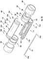
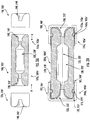
- FIGS. 1A-1B and 2A-2B illustrate exemplary embodiments of a fuse in accordance with the present disclosure.
- Exemplary embodiments of the fuse in the present disclosure may include a cartridge fuse and/or a surface mount fuse.
- a fuse 100, 100' may include a fuse body 105, 105'.
- the fuse body 105, 105' may be formed of a single piece (see FIGS. 3A-3C ), although in some embodiments the fuse body 105, 105' may be formed of more than one component, e.g., a split body.
- the fuse body 105, 105' may include a first portion 110, 110' and a second portion 115, 115'.
- the fuse body 105, 105 may be an elongated body, and may have a first end 105a, 105a', a central portion 105c, 105c' and a second end 105b, 105b'.
- the first portion 110, 110' may be an elongated body and may have a first end 110a, 110a', a central portion 110c, 110c', and a second end 110b, 110b'
- the second portion 115, 115' may be an elongated body and may have a first end 115a, 115a', a central portion 115c, 115c', and a second end 115b, 115b'.
- the first and second portions 110, 110', 115, 115' may be symmetrical to define a single fuse body when assembled.
- the respective first ends 110a, 110a', 115a, 115a' may be aligned to each other, and the respective second ends 110b, 110b', 115b, 115b' may be aligned to each other.
- the fuse body 105 may be formed in a substantially rectangular shape
- FIG. 1B illustrates the fuse body 105' being formed in a substantially cylindrical shape, although the fuse body may be configured in any shape in accordance with the present disclosure.
- discussion of the fuse body 105, 105' throughout may also include each of the first and second portions 110, 110', 115, 115' (e.g., reference to a first end of the fuse body 105a, 105a' may include a first end of the first portion 110a, 110a' and a first end of the second portion1 115a, 115a', etc.).
- the fuse body 105 may be formed of a non-conductive material, such as ceramic or a plastic or composite material. In some embodiments, as described below with respect to FIGS. 5B , 6B-6D , at least a portion of the fuse body may be formed of a conductive material, such that the fuse may not require a separate electrical conductor.
- the fuse body 105, 105' may have an internal cavity 120, 120'.
- the cavity 120, 120' may be at least partially formed in each of the first and second portions 110, 110' 115, 115' although it is understood that the cavity 120, 120' may be wholly disposed in either of the first or second portions 110, 110', 115, 115' of the fuse body 105, 105'.
- the cavity 120, 120' may extend from the first end 105a, 105a', through the fuse body and to the second end 105b, 105b', and may be any shape formed in the fuse body 105, 105'.
- the cavity 120, 120' may have a contour such that at least a portion of the cavity at the first end 105a, 105a' and/or the second end 105b, 105b' may be narrower than the cavity at the central portion 105c, 105c'.
- the cavity 120, 120' may be configured to receive a fusible element 125, 125', such that having a narrower cavity portion at the first and/or second ends of the fuse body 105a, 105a', 105b, 105b' may be advantageous for alignment of the fusible element 125, 125' during assembly.
- the fusible element 125, 125' may be positioned in the cavity 120, 120' such that the fusible element 125, 125' is centered relative to the fuse body 105, 105'. In some embodiments, the fusible element 125, 125' does not contact the fuse body 105, 105', e.g., the fusible element 125, 125' is surrounded by air. In some embodiments, a filler may be included to fill the cavity 120, 120', such as silica, sand, or other arc-quenching material.
- the fusible element 125, 125' may be a wire, a stamped element, or other conductive component, may be formed straight, or include one or more curvatures, and may be extendable in the cavity 120, 120' of the fuse body 105, 105' and attachable at a first end 125a, 125a' and a second end 125b, 125b'.
- the fusible element 125, 125' may be attachable to a first electrical conductor 130, 130' to form a first connection, and a second electrical conductor 135, 135' to form a second connection.
- the fusible element 125, 125' may be attachable to the first and second electrical conductors 130, 130', 135, 135' by weld, solder, epoxy, or combinations thereof.
- the fusible element 125, 125' may be inserted and/or attached to the first and second electrical conductors 130, 130', 135, 135' after the electrical conductors have been attached to the fuse body 105, 105'.
- the solder or weld may be lead (Pb) free.
- the fusible element 125, 125' may be attachable to the first and second electrical conductors 130, 130', 135, 135' by winding, or wrapping, a respective end 125a, 125a', 125b, 125b' of the fusible element around the respective first and second electrical conductor 130, 130', 135, 135'.
- the first and second electrical conductors 130, 130' 135, 135' may be formed as a termination, or an inner cap, e.g., extending over and at least partially enclosing a first end 105a, 105a' of the fuse body and a second end 105b, 105b' of the fuse body.
- the electrical conductors may be referred to as termination and/or inner caps interchangeably, and may be a cap, clips, or metallization, or combinations thereof.
- the inner cap 130, 130', 135, 135' may clamp, or retain, the respective portions 110, 110', 115, 115' in alignment thereby defining the fuse body 105, 105'.
- the fuse body may be formed without solder, e.g., a solderless, fuse body.
- first and second inner caps 130, 130', 135, 135' may be formed to mate with the respective first and second ends of the fuse body 105a, 105a', 105b, 105b'.
- first and second inner caps 130, 130' 135, 135' may have a conical curvature 140, 140' extending inwardly into the respective cap.
- the conical curvature 140, 140' may be configured to mate with the respective first end and second end of the fuse body 105a, 105a', 105b, 105b'.
- the first end 105a, 105a' (e.g., the first ends 110a, 115a, 110a', 115a') may have a matching conical curvature 145, 145'
- the second end 105b, 105b' (e.g., the second ends 110b, 115b, 110b', 115b') may have a matching conical curvature 150, 150' such that the inner caps may substantially fit over the respective ends of the fuse body, e.g., as indicated by direction arrows "A".
- the conical curvature 145, 145', 150, 150' may also extend inwardly towards the central portion 105c of the fuse body.
- the conical curvature 145, 145', 150, 150' may transition into the cavity 120, 120'. As described above, the narrower portions of the cavity 120, 120' may extend at least partially to the conical curvature 145, 145', 150, 150'. In some embodiments, the conical curvature 140, 140' of the inner caps 130, 130', 135, 135' and/or the conical curvature of the fuse body 145, 145', 150, 150' are formed in a trumpet bell shape.
- the conical curvature 140, 140' of the inner caps 130, 130', 135, 135' and/or the conical curvature of the fuse body 145, 145', 150, 150' may aid in alignment of the fusible element 125, 125', such that the fusible element 125, 125' is centered in the fuse body 105, 105'.
- the inner cap 130, 130', 135, 135' may be crimped onto the respective end 105a, 105a', 105b, 105b' of the fuse body.
- the inner cap 130, 130', 135, 135' may have a pre-formed groove 155, 155' extending around an outer circumference 160, 160'.
- a first groove 165, 165' may be pre-formed on an outer circumference 170, 170' at the first end 105a, 105a' of the fuse body
- a second groove 175, 175' may be pre-formed on the outer circumference 170, 170' at the second end 105b, 105b' of the fuse body.
- the grooves may not be pre-formed, but may be created when the inner cap is attached, e.g., crimped to the fuse body.
- the groove 155, 155' may be configured to lock into the respective first and second grooves 165, 165', 170, 170', thereby clamping, or retaining the fuse body 105, 105' by the inner caps 130, 130', 135, 135'.
- the grooves 155, 155', 165, 165', 170, 170' may be formed after assembling the inner caps onto the fuse body, e.g., the inner caps and the fuse body may be crimped together to form the respective grooves.
- the inner cap 130, 130', 135, 135' may be shaped to conform to the shape of the fuse body.
- the inner cap 130, 135 may be rectangular or square in shape to mate with the rectangular fuse body 105.
- the inner cap 130', 135' may be circular or cylindrical in shape to mate with the cylindrical fuse body 105'.
- the electrical conductors 130, 130', 135, 135' may be formed of an electrically conductive material, such as a metal, including but not limited to brass, copper, copper alloy, gold, silver, or tin, or alloys thereof. In some embodiments, the material may be plated with an electrically conductive material.
- the fusible element 125, 125' may be attached at a first connection to the first inner cap 130, 130' and attached at a second connection to the second inner cap 135, 135'.
- the conical curvature 140, 140' of the first and second inner caps 130, 130', 135, 135' may aid in alignment of the fusible element 125, 125' for attachment.
- the conical curvature 140, 140' may allow a visual confirmation of the first connection and the second connection. For example, in embodiments where the fusible element is welded, or soldered, to the inner caps 130, 130', 135, 135', it may be advantageous to inspect the joint quality.
- fuse body 105, 105' and the inner cap 130, 130', 135, 135' may be configured such that the first connection and the second connection may be inspectable without removal of the inner cap from the fuse body. In this manner, the first and second portions may remain in alignment and retained by the inner caps.
- a first termination, or outer cap 180, 180' may be positioned over at least a portion of the first inner cap 130, 130', and/or the first end 105a, 105a' of the fuse body.
- a second outer termination, or cap 185, 185' may be positioned over at least a portion of the second inner cap 135, 135', and/or the second end 105b, 105b' of the fuse body.
- the first and/or second outer terminations may be formed as caps, clips, or metallization, or combinations thereof.
- the first and second outer caps 180, 180', 185, 185' may be a press fit, or interference fit, over the respective inner cap 130, 130', 135, 135'.
- the outer caps may be fixed over the respective inner caps, so that the outer caps may not be removed after assembly.
- the outer cap 180, 180', 185, 185' may be formed in a shape to conform with the inner cap 130, 130', 135, 135' and/or the fuse body 105, 105'.
- the first and second outer cap 180, 185 may be substantially rectangular or square to mate with the inner cap 130, 135 and/or the fuse body 105.
- the first and second outer cap 180, 185 may be substantially cylindrical or circular to mate with the inner cap 130', 135' and/or the fuse body 105'.
- the fuse body may be configured as a solderless design, such that no additional solder is needed to configure a fuse, e.g., fuse 300, 300' of FIGS. 9A-9B .
- the fuse body may have a first end 310a, 310a', 310a", and a second end 310b, 310b', 310b", and a central portion 310c, 310c', 310c" disposed therebetween.
- the central portion 310c, 310c', 310c" may be formed as a plate, although any configuration is envisioned to form a fuse body in a desired shape.
- the fuse body 305, 305', 305" may be integrally formed, or assembled to form, a single piece, and may be formed of a non-conductive material such as ceramic, plastic or composite or combinations thereof.
- the fuse body 305, 305', 305" may be at least partially formed of a conductive material.
- an electrical conductor 345, 350 formed as conductive plates may be disposed along an edge of the fuse body 305.
- the fuse body 305, 305', 305" may be substantially rectangular, but it is also envisioned that the fuse body may be any shape as desired for connection with other electrical components.
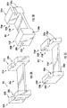
- the first and second ends of the fuse body 310a, 310b, 310a', 310b', 310a", 310b" may include one or more slots, or notches. As shown in FIG. 3A , a first slot 320a may be disposed in a first edge 315a of the first end of the fuse body, and a second slot 320b may be disposed in a second edge 315b of the second end of the fuse body.
- the first and second edges 315a, 315b may be a top surface of the respective first and second ends of the fuse body, and the first and second slots 320a, 320b may be a depression, or a recessed area, on at least a portion of the first and second edges 315a, 315b, at any depth into the first and second edges 315a, 315b, e.g., to receive at least a portion of an electrical conductor (see FIGS. 5A-6D ).
- the first and second slots 320a, 320b may be formed in the respective first and second edges 315a, 315b transversely, e.g., substantially perpendicular to a length of the edge, and/or longitudinally, e.g., along a length of the edge. In some embodiments, the first and second slots 320a, 320b may extend around the respective ends 310a, 310b so that each face has a depression, or recessed area.
- slots or notches may be disposed on side faces of the fuse body. As shown in FIG. 3B , a slot 320a' may be disposed on a side face 325a of a first end 310a'. In some embodiments, the slot 320a' may be disposed on opposite side face 325b of the first end 310a'. It is also understood that slots may be disposed on both side faces 325a, 325b of the first end 310a'. Similarly, a slot 320b' may be disposed on a side face 330a of a second end 310b', on opposite side face 330b of the second end 310b', or both.
- the first and second slots 320a', 320b' may be formed in the respective side faces 325a, 325b, 330a, 330b transversely, e.g., substantially perpendicular to a length of the fuse body, and/or longitudinally, e.g., substantially parallel to length of the fuse body.
- the slots 320a', 320b' may be formed at any position on the side faces 325a, 325b, 330a, 330b, e.g., towards edges 315a', 315b', or the top surfaces of the first and second ends 310a', 310b', and/or towards a bottom face of the first and second ends 310a', 310b'.
- the slots 320a', 320b' may be at least partially formed as a recess, or depression, into the side faces 325a, 325b, 330a, 330b, and may be any depth to receive at least a portion of an electrical conductor (see FIGS. 5A-6D ).
- slots may be formed into each side face of each end of the fuse body.
- a first end 310a" may have a first slot 335a formed into a first side face 325a", and a second slot 335b formed into a second side face 325b".
- a second end 310b" may have a first slot 340a formed into a first side face 330a" and a second slot 340b formed into a second side face 330b".
- four slots are shown as being formed as recessions, or depressions, into the side faces, additional or fewer slots are also envisioned.
- the slots 335a, 335b, 340a, 340b may be formed as notches, such that the first end 310a" and the second end 310b" are T-slots. It is also envisioned that the slots 335a, 335b, 340a, 340b may at least be partially formed as a recess, or depression, into the side faces 325a", 325b", 330a", 330b", and may be any depth to receive at least a portion of an electrical conductor (see FIGS. 5A-6D ).
- the slots 320a, 320b, 320a', 320b', 335a, 335b, 340a, 340b may be formed into the fuse body as guides for an electrical conductor, such that the electrical conductor is properly aligned for connection with a fusible element. Additionally, the slots may be positioned on the fuse body such that connections between a fusible element and an electrical conductor may be visible for inspection.
- an electrical conductor 345, 350 may be formed as clip, e.g., a C-clip, and may be attachable to the fuse body.
- an electrical conductor 345, 350 may be formed as a coating, e.g., a metallization, of a portion of the fuse body. As shown in FIG. 4 , an electrical conductor 345, 350 may include a first top portion 345a, 350a, a second side portion 345b, 350b, and a third bottom portion 345c, 350c, formed as a "C" or "U" shape.
- a first electrical conductor 345 may be positioned with respect to a first end 310a, and a second electrical conductor 350 may be positioned with respect to a second end 310b.
- the first electrical conductor 345 may be attached to the first end 310a of the fuse body such that the first, or top, portion 345a is disposed in the first slot 320a.
- the second, or side, portion 345b may be in alignment (e.g., substantially parallel) with an outward face 355 of the first end 310a.
- the third, or bottom, portion 345c may be in alignment (e.g., substantially parallel) with a bottom face 360 of the first end 310a.
- the second electrical conductor 350 may be attached to the second end 310b of the fuse body such that the first portion 350a is disposed in the second slot 320b.
- the second portion 350b may be in alignment (e.g., substantially parallel) with an outward face 365 of the second end 310b.
- the third portion 350c maybe in alignment (e.g., substantially parallel) with a bottom face 370 of the second end 310b.
- the second portion 350b may be formed to fit within the slot 320a, 320b (see FIG. 5A ), e.g., a width of the first portion 345a and the second portion 345b may be substantially the same.
- the second portion 350b may substantially extend over and/or cover the respective first and/or second end 310a, 310b (see FIG. 4 ), so that a width of the second portion 350b may be greater than a width of the first portion 350b.
- the first and second electrical conductors 345, 350 may be in electrical connection by a fusible element 375.
- the fusible element 375 may be attachable to the first electrical conductor 345 at a first end 375a to form a first connection and a second electrical conductor 350 at a second end 375b to form a second connection.
- the fusible element may be attachable to the first and second electrical conductors 345, 350 by weld, solder, epoxy, or combinations thereof.
- electrical conductors may be integrally formed with a fusible element.
- FIGS. 7C, 7E, 7F illustrate exemplary embodiments of a fusible element and/or electrical conductors 700-735, which may be any of a wire, stamped element, or other conductor, and may be straight, coiled, or include one or more curvatures, bends, or formations with respect to the fuse body. It is understood that the electrical conductors may include one or more openings, or pre-formed weak spots (see FIGS. 7C, 7E, 7F ), such that in an electrical event, a desired portion may be configured to fail.
- the fusible element 375 may be attachable to a metallization of a portion of the fuse body, e.g., as shown in FIG. 5B .
- the first end 375a may be attachable at a first slot 320a, which may have a coating, metallization, or other electrical conductor 345, 350 as part of the fuse body 305, to form a first connection.
- the second end 375b may be attachable at a second slot 320b, which may have a coating, metallization, or other electrical conductor as part of the fuse body 305, to form a second connection.
- the electrical conductor may be a wire, or stamped element, which may be formable at least partially around the slots 320a, 320b, 320a', 320b', 335a, 335b, 340a, 340b.
- a fusible element 380 may be positioned with respect to the fuse body such that a first end 380a of the fusible element is disposed in the slot 320a', and a second end 380b of the fusible element is disposed in the slot 320b'.
- the fusible element may be attached to the fuse body directly via weld, solder, epoxy, or combinations thereof.
- the fusible element 380 may be attached to the fuse body by winding, wrapping, or forming, respective first and/or second ends 380a, 380b around the fuse body 305'.
- FIG. 6A illustrates a fusible element 380 wrapped around slots 320a', 320b' formed into side faces of the fuse body, it is understood and envisioned that a fusible element may be attachable (e.g., winding, wrapping, forming, welding, soldering, epoxy, or combinations thereof) to a fuse body 305, 305', 305" having slots in any configuration, e.g., slots may be disposed in any of the edges, or top surfaces, and/or side faces.
- a fusible element may be attachable (e.g., winding, wrapping, forming, welding, soldering, epoxy, or combinations thereof) to a fuse body 305, 305', 305" having slots in any configuration, e.g., slots may be disposed in any of the edges, or top surfaces, and/or side faces.
- electrical conductors may be integrally formed with, or formed as separate components and welded to, a fusible element to attach to the fuse body 305".
- electrical conductors 645, 650 may be attachable to a fusible element 675, and may be welded, or soldered, together.
- the electrical conductors 645, 650 may be similar to electrical conductor 345, 350, e.g., formed in a "C" or "U" shape.
- a first out face, or top portion 645a, 650a may have two prongs, e.g., 645a1, 645a2, 650a1, 650a2, to at least partially be received in the slots 335a, 335b, 340a, 340b positioned on the side faces of the first and second ends of the fuse body.
- the prongs may be formed to accommodate the T-slot shape.
- the fusible element 675 may be configured to attach to the electrical conductor 645, 650.
- a first end 675a may similarly have two prongs to mate with the prongs 645a1, 645a2, and a second end 675b may have two prongs to mate with the prongs 650a1, 650a2.
- FIGS. 6C-6D illustrate an integrally formed electrical conductor and fusible element, and is referred throughout as the electrical conductor 605, 610.
- the electrical conductor 605, 610 may be a stamped element, such as a sheet metal, and formed into a shape configured around the fuse body 305".
- the electrical conductor 605, 610 may have a first portion 615, 620 as prongs, or parallel elements 615a, 615b, 620a, 620b, which may extend through the respective slots 335a, 335b, 340a, 340b.
- element 615a, 620a may extend from the first end 310a" through the first slot 335a to the second end 310b" through the second slot 340a.
- element 615b, 620b may extend from the first end 310a" through the third slot 335b to the second end 310b" through the second slot 340b.
- the elements 615a, 615b, 620a, 620b may be substantially parallel to each other and extend longitudinally along the fuse body 305".
- the first portion 615, 620 may extend into second and third portion, 625 and 630.
- the second and third portions 625, 630 may be aligned with the respective first and second ends 310a", 310b", e.g., may extend substantially parallel to an outer face, or top portion 650a, 650b of the first and second ends 310a", 310b".
- the second and third portions 625, 630 may be a single piece (see FIG. 6C ), although in other embodiments, the second and third portions 625, 630 may extend as separate, parallel elements (see FIG. 6D ). In some embodiments, a fourth and fifth portion 635, 640 may extend from the respective second and third portion 625, 630 along a bottom face 655 of the fuse body.
- the first, second, third, fourth, and fifth portions may be formed by placing the stamped element over the fuse body, e.g., so the first portion is substantially parallel along a top surface of the fuse body, and bending, or forming, the second, third, fourth, and fifth portions accordingly.
- the second and third portions may be substantially perpendicular to the first portion
- the fourth and fifth portions may be substantially perpendicular to the first portion and the respective second and third portions.
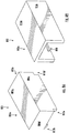
- a cover 805, 810 may be positioned over at least a portion of the fuse body, electrical conductor, and/or fusible element. It is understood that prior to assembling the cover 805, 810, any electrical connections, e.g., welds, solder, wrapping, windings, etc., may be visually inspected to verify the attachments.
- the cover may be formed to mate with the fuse body, electrical conductor, and/or the fusible element.
- the cover may be substantially rectangular, e.g., a box-shape, although the cover may be any shape to at least partially enclose the fuse body and other components.
- the cover 805 may have a top face 805a and surrounding side faces 805b-805e, such that the cover 805 may be placed over the fuse body 305, 305', 305", electrical conductors 345, 350, 645, 650, 605, 610, and/or fusible element 375, 380, 675.
- the cover 805 may include one or more locking features 815, e.g., locking features 815a-815d.
- the locking features 815a-815d may be formed in respective corners of the cover 805, as shown in FIG. 8A .
- the locking features 815a-815d may be formed to lock, or snap-fit, with the fuse body 305, 305', 305".
- the locking features 815a-815d may have protrusions, or recessions, or both, formed to interlock with equivalent recessions, or protrusions, or both, on the fuse body.
- a fuse 300 (see FIG. 9A ) may be subsequently connected to other electrical components. As shown, at least a portion of the electrical conductors may be extendable out of the cover for electrically connecting to the other electrical components.
- a cover 810 may have a top face 810a and side faces 810c, 810e, such that end side faces are open, e.g., side faces aligned with the first and second ends of the fuse body.
- the electrical conductors 345, 350, 645, 650, or portions 625, 630 of conductors may be electrically connectable to other electrical components.
- the cover 810 may include locking features 820, e.g., formed on an internal surface of side faces 810c, 810e.
- Locking features 820 may be formed as protrusions, recesses, or both, and may be configured to interlock with equivalent recesses, protrusions, or both, on the fuse body.
- the locking features 820 may be a snap-fit to lock the cover 810 onto the fuse body, to at least partially cover the fuse body, electrical conductors, and/or fusible elements.
- Coupled and “connected” along with their derivatives. These terms are not intended as synonyms for each other. For example, some embodiments may be described using the terms “connected” and/or “coupled” to indicate that two or more elements are in direct physical or electrical contact with each other. The term “coupled,” however, may also mean that two or more elements are not in direct contact with each other, but yet still co-operate or interact with each other.
Landscapes
- Engineering & Computer Science (AREA)
- Manufacturing & Machinery (AREA)
- Chemical & Material Sciences (AREA)
- Composite Materials (AREA)
- Fuses (AREA)
Abstract
Description
- Embodiments of the present disclosure relate generally to the field of fuses, and more particularly to a fuse configured to facilitate visible inspection of a fusible element.
- Fuse bodies for different applications are commonly configured such that a fusible element is enclosed in a fuse body during assembly and is not visible for inspection of connection points to an electrical conductor. If the fusible link is not properly connected to the electrical conductor, the fuse may be damaged or inoperable, which may lead to failure during an electrical event and damage to sensitive electrical components. Additionally, fuses may include several separate components requiring welding or soldering for assembly, thereby complicating and increasing the cost for assembly/disassembly of the fuse, as well as introducing additional potential failure points of the fuse.
- It is with respect to these and other considerations that the present improvements may be useful.
- This Summary is provided to introduce a selection of concepts in a simplified form that are further described below in the Detailed Description. This Summary is not intended to identify key features or essential features of the claimed subject matter, nor is it intended as an aid in determining the scope of the claimed subject matter.
- According to an exemplary embodiment of the present disclosure, a fuse may include a fuse body having a first portion and a second portion. The first and second portions may be configured to mate together thereby forming an internal cavity. A first inner termination may be at least partially attachable to the first and second portions of the fuse body at a first end. A second inner termination may be at least partially attachable to the first and second portions of the fuse body at a second end. A fusible element may be disposed in the cavity of the fuse body and extendable from the first inner termination at the first end of the fuse body to the second inner termination at the second end of the fuse body. The fusible element may be attachable to the first inner termination at a first connection and the second inner termination at a second connection such that the first and second connections may be inspectable when the fuse is in an assembled state.
- In various and foregoing embodiments of the present disclosure, a first outer termination may be positioned over the first inner termination at the first end of the fuse body. A second outer termination may be positioned over the second inner termination at the second end of the fuse body. The first outer termination, the second outer termination, the first inner termination, or the second inner termination, or combinations thereof, may be formed as a cap, a clip, or a metallization, or combinations thereof. A contour of the cavity may be narrower at the first and second ends of the fuse body, and wider in a central portion of the fuse body. The first and second inner terminations may be formed to mate with the respective first and second ends of the fuse body. The first and second ends of the fuse body may have a conical curvature extending into the cavity of the fuse body, and the inner terminations may have respective mating conical curvatures, such that the fusible element may be insertable and centered in the cavity. The first and second inner terminations may be crimped onto the respective first and second ends of the fuse body via grooves. The first and second outer terminations may be crimped onto the respective first and second ends of the fuse body, or the respective first and second inner terminations, or both. The fusible element may be attachable to the respective first and second inner terminations by solder, weld, epoxy, or combinations thereof. The fusible element may be attachable by winding around an outer circumference of the respective first and second inner terminations.
- According to an exemplary embodiment of the present disclosure, a fuse may include a fuse body including an elongated body having a first end and a second end. The first end and the second end may each have one or more slots. A fusible element may be extendable from the one or more slots of the first end of the fuse body to the one or more slots of the second end of the fuse body. A cover may be included to at least partially enclose the fuse body and the fusible element. The cover may have one or more lockable features to at least partially retain the fuse body, the fusible element, or both.
- In various of the foregoing and other embodiments of the present disclosure, a first electrical conductor may be disposed at the first end of the fuse body. A second electrical conductor may be disposed at the second end of the fuse body, and the fusible element may be attachable to the first electrical conductor and extendable along the elongated body of the fuse body and attachable to the second electrical conductor. The fuse body may be formed of an electrically conductive material such that the fusible element may be directly connectable to the fuse body. A first slot may be disposed on a top surface of the first end of the fuse body, and a second slot may be disposed on a top surface of the second end of the fuse body, such that the fusible element may be centered along the fuse body. At least a portion of a first electrical conductor may be positioned in the first slot and at least a portion of a second electrical conductor is positioned in the second slot, and the fusible element may be attachable to the first electrical conductor in the first slot and the second electrical conductor in the second slot. The first slot may be disposed on a first side surface of the first end of the fuse body, and a second slot may be disposed on a first side surface of the second end of the fuse body. At least a portion of a first electrical conductor may be positioned in the first slot and at least a portion of a second electrical conductor is positioned in the second slot, and the fusible element may be attachable to the first electrical conductor in the first slot and the second electrical conductor in the second slot. A third slot may be disposed on a second side surface opposite the first slot on the first side surface of the first end of the fuse body, and a fourth slot may be disposed on a second surface opposite the first slot of the first side surface of the second end of the fuse body. The first side surface of the first end of the fuse body may be opposite of the first side surface of the second end of the fuse body, such that the fusible element may be diagonally extendable along the elongated body of the fuse body. The fusible element may be attachable to the fuse body, the first electrical conductor, the second electrical conductor, or combinations thereof, by solder, weld, epoxy, winding, forming, or combinations thereof.
- By way of example, specific embodiments of the disclosed device will now be described, with reference to the accompanying drawings, in which:
-
FIGS. 1A-1B illustrate exemplary embodiments of a fuse in accordance with the present disclosure; -
FIG. 2A illustrates a top sectional view of an exemplary embodiment of a fuse in accordance with the present disclosure; -
FIG. 2B illustrates a side sectional view of an exemplary embodiment of a fuse in accordance with the present disclosure; -
FIGS. 3A-3C illustrate exemplary embodiments of a fuse body in accordance with the present disclosure; -
FIG. 4 illustrates an exemplary embodiment of an electrical conductor of a fuse in accordance with the present disclosure; -
FIGS. 5A-5B illustrate exemplary embodiments of a fuse in accordance with the present disclosure; -
FIGS. 6A-6D illustrate exemplary embodiments of a fuse in accordance with the present disclosure; -
FIGS. 7A-7H illustrate exemplary embodiments of a fusible element in accordance with the present disclosure; -
FIGS. 8A-8B illustrate exemplary embodiments of a fuse cover in accordance with the present disclosure; and -
FIGS. 9A-9B illustrate exemplary embodiments of an assembled fuse in accordance with the present disclosure. - A fuse in accordance with the present disclosure will now be described more fully hereinafter with reference to the accompanying drawings, in which certain exemplary embodiments of the fuse are presented. The fuse may be embodied in many different forms and is not to be construed as being limited to the embodiments set forth herein. These embodiments are provided so that this disclosure will be thorough and complete, and will fully convey the scope of the fuse to those skilled in the art. In the drawings, like numbers refer to like elements throughout unless otherwise noted.
-
FIGS. 1A-1B and 2A-2B illustrate exemplary embodiments of a fuse in accordance with the present disclosure. Exemplary embodiments of the fuse in the present disclosure may include a cartridge fuse and/or a surface mount fuse. Afuse 100, 100' may include afuse body 105, 105'. Thefuse body 105, 105' may be formed of a single piece (seeFIGS. 3A-3C ), although in some embodiments thefuse body 105, 105' may be formed of more than one component, e.g., a split body. As shown inFIGS. 1A-1B and 2A-2B, thefuse body 105, 105' may include afirst portion 110, 110' and asecond portion 115, 115'. Thefuse body first end central portion second end first portion 110, 110' may be an elongated body and may have afirst end central portion second end second portion 115, 115' may be an elongated body and may have afirst end central portion second end second portions first ends FIG. 1A , thefuse body 105 may be formed in a substantially rectangular shape, andFIG. 1B illustrates the fuse body 105' being formed in a substantially cylindrical shape, although the fuse body may be configured in any shape in accordance with the present disclosure. It is understood that discussion of thefuse body 105, 105' throughout may also include each of the first andsecond portions fuse body first portion - The
fuse body 105 may be formed of a non-conductive material, such as ceramic or a plastic or composite material. In some embodiments, as described below with respect toFIGS. 5B ,6B-6D , at least a portion of the fuse body may be formed of a conductive material, such that the fuse may not require a separate electrical conductor. - The
fuse body 105, 105' may have aninternal cavity 120, 120'. In some embodiments, thecavity 120, 120' may be at least partially formed in each of the first andsecond portions 110, 110' 115, 115' although it is understood that thecavity 120, 120' may be wholly disposed in either of the first orsecond portions fuse body 105, 105'. Thecavity 120, 120' may extend from thefirst end second end fuse body 105, 105'. In embodiments, thecavity 120, 120' may have a contour such that at least a portion of the cavity at thefirst end second end central portion cavity 120, 120' may be configured to receive afusible element 125, 125', such that having a narrower cavity portion at the first and/or second ends of thefuse body fusible element 125, 125' during assembly. - The
fusible element 125, 125' may be positioned in thecavity 120, 120' such that thefusible element 125, 125' is centered relative to thefuse body 105, 105'. In some embodiments, thefusible element 125, 125' does not contact thefuse body 105, 105', e.g., thefusible element 125, 125' is surrounded by air. In some embodiments, a filler may be included to fill thecavity 120, 120', such as silica, sand, or other arc-quenching material. - The
fusible element 125, 125' may be a wire, a stamped element, or other conductive component, may be formed straight, or include one or more curvatures, and may be extendable in thecavity 120, 120' of thefuse body 105, 105' and attachable at afirst end second end fusible element 125, 125' may be attachable to a firstelectrical conductor 130, 130' to form a first connection, and a secondelectrical conductor 135, 135' to form a second connection. In some embodiments, thefusible element 125, 125' may be attachable to the first and secondelectrical conductors fusible element 125, 125' may be inserted and/or attached to the first and secondelectrical conductors fuse body 105, 105'. In some embodiments, the solder or weld may be lead (Pb) free. In some embodiments, thefusible element 125, 125' may be attachable to the first and secondelectrical conductors respective end electrical conductor - The first and second
electrical conductors 130, 130' 135, 135' may be formed as a termination, or an inner cap, e.g., extending over and at least partially enclosing afirst end second end first portion 110, 110' and asecond portion 115, 115' of thefuse body 105, theinner cap respective portions fuse body 105, 105'. In this manner, the fuse body may be formed without solder, e.g., a solderless, fuse body. - In embodiments, the first and second
inner caps fuse body inner caps 130, 130' 135, 135' may have aconical curvature 140, 140' extending inwardly into the respective cap. Theconical curvature 140, 140' may be configured to mate with the respective first end and second end of thefuse body first end conical curvature 145, 145', and thesecond end conical curvature 150, 150' such that the inner caps may substantially fit over the respective ends of the fuse body, e.g., as indicated by direction arrows "A". Theconical curvature central portion 105c of the fuse body. - The
conical curvature cavity 120, 120'. As described above, the narrower portions of thecavity 120, 120' may extend at least partially to theconical curvature conical curvature 140, 140' of theinner caps fuse body conical curvature 140, 140' of theinner caps fuse body fusible element 125, 125', such that thefusible element 125, 125' is centered in thefuse body 105, 105'. - In some embodiments, the
inner cap respective end inner cap pre-formed groove 155, 155' extending around anouter circumference 160, 160'. Similarly, afirst groove 165, 165' may be pre-formed on anouter circumference 170, 170' at thefirst end second groove 175, 175' may be pre-formed on theouter circumference 170, 170' at thesecond end FIG. 2B , thegroove 155, 155' may be configured to lock into the respective first andsecond grooves fuse body 105, 105' by theinner caps grooves - The
inner cap FIG. 1A , theinner cap rectangular fuse body 105. As shown inFIG. 1B , the inner cap 130', 135' may be circular or cylindrical in shape to mate with the cylindrical fuse body 105'. - The
electrical conductors - As described above, the
fusible element 125, 125' may be attached at a first connection to the firstinner cap 130, 130' and attached at a second connection to the secondinner cap 135, 135'. Theconical curvature 140, 140' of the first and secondinner caps fusible element 125, 125' for attachment. Additionally, theconical curvature 140, 140' may allow a visual confirmation of the first connection and the second connection. For example, in embodiments where the fusible element is welded, or soldered, to theinner caps fuse body 105, 105' and theinner cap - In some embodiments, a first termination, or
outer cap 180, 180' may be positioned over at least a portion of the firstinner cap 130, 130', and/or thefirst end cap 185, 185' may be positioned over at least a portion of the secondinner cap 135, 135', and/or thesecond end outer caps inner cap outer cap inner cap fuse body 105, 105'. As shown inFIG. 1A , the first and secondouter cap inner cap fuse body 105. As shown inFIG. 1B , the first and secondouter cap - Referring now to
FIGS. 3A-3C , additional embodiments of afuse body fuse 300, 300' ofFIGS. 9A-9B . The fuse body may have afirst end second end central portion central portion fuse body fuse body FIG. 5B , anelectrical conductor fuse body 305. Thefuse body - In embodiments, the first and second ends of the
fuse body FIG. 3A , afirst slot 320a may be disposed in afirst edge 315a of the first end of the fuse body, and asecond slot 320b may be disposed in asecond edge 315b of the second end of the fuse body. The first andsecond edges second slots second edges second edges FIGS. 5A-6D ). The first andsecond slots second edges second slots respective ends - In some embodiments, slots or notches may be disposed on side faces of the fuse body. As shown in
FIG. 3B , aslot 320a' may be disposed on aside face 325a of afirst end 310a'. In some embodiments, theslot 320a' may be disposed onopposite side face 325b of thefirst end 310a'. It is also understood that slots may be disposed on both side faces 325a, 325b of thefirst end 310a'. Similarly, aslot 320b' may be disposed on aside face 330a of asecond end 310b', onopposite side face 330b of thesecond end 310b', or both. The first andsecond slots 320a', 320b' may be formed in the respective side faces 325a, 325b, 330a, 330b transversely, e.g., substantially perpendicular to a length of the fuse body, and/or longitudinally, e.g., substantially parallel to length of the fuse body. Theslots 320a', 320b' may be formed at any position on the side faces 325a, 325b, 330a, 330b, e.g., towardsedges 315a', 315b', or the top surfaces of the first andsecond ends 310a', 310b', and/or towards a bottom face of the first andsecond ends 310a', 310b'. Theslots 320a', 320b' may be at least partially formed as a recess, or depression, into the side faces 325a, 325b, 330a, 330b, and may be any depth to receive at least a portion of an electrical conductor (seeFIGS. 5A-6D ). - As shown in
FIG. 3C , slots may be formed into each side face of each end of the fuse body. Afirst end 310a" may have afirst slot 335a formed into afirst side face 325a", and asecond slot 335b formed into asecond side face 325b". Asecond end 310b" may have afirst slot 340a formed into afirst side face 330a" and asecond slot 340b formed into asecond side face 330b". Although four slots are shown as being formed as recessions, or depressions, into the side faces, additional or fewer slots are also envisioned. Theslots first end 310a" and thesecond end 310b" are T-slots. It is also envisioned that theslots FIGS. 5A-6D ). - It is envisioned that the
slots - At least a portion of an electrical conductor may be disposed in the
slots respective fuse body electrical conductor electrical conductor FIG. 4 , anelectrical conductor top portion 345a, 350a, asecond side portion third bottom portion - Referring now to
FIGS. 5A-5B , a firstelectrical conductor 345 may be positioned with respect to afirst end 310a, and a secondelectrical conductor 350 may be positioned with respect to asecond end 310b. In some embodiments, the firstelectrical conductor 345 may be attached to thefirst end 310a of the fuse body such that the first, or top,portion 345a is disposed in thefirst slot 320a. The second, or side,portion 345b may be in alignment (e.g., substantially parallel) with anoutward face 355 of thefirst end 310a. The third, or bottom,portion 345c may be in alignment (e.g., substantially parallel) with abottom face 360 of thefirst end 310a. Similarly, the secondelectrical conductor 350 may be attached to thesecond end 310b of the fuse body such that the first portion 350a is disposed in thesecond slot 320b. Thesecond portion 350b may be in alignment (e.g., substantially parallel) with anoutward face 365 of thesecond end 310b. Thethird portion 350c maybe in alignment (e.g., substantially parallel) with abottom face 370 of thesecond end 310b. In embodiments, thesecond portion 350b may be formed to fit within theslot FIG. 5A ), e.g., a width of thefirst portion 345a and thesecond portion 345b may be substantially the same. In other embodiments, thesecond portion 350b may substantially extend over and/or cover the respective first and/orsecond end FIG. 4 ), so that a width of thesecond portion 350b may be greater than a width of thefirst portion 350b. - The first and second
electrical conductors fusible element 375. In some embodiments, thefusible element 375 may be attachable to the firstelectrical conductor 345 at afirst end 375a to form a first connection and a secondelectrical conductor 350 at asecond end 375b to form a second connection. The fusible element may be attachable to the first and secondelectrical conductors FIGS. 7A-7H illustrate exemplary embodiments of a fusible element and/or electrical conductors 700-735, which may be any of a wire, stamped element, or other conductor, and may be straight, coiled, or include one or more curvatures, bends, or formations with respect to the fuse body. It is understood that the electrical conductors may include one or more openings, or pre-formed weak spots (seeFIGS. 7C, 7E, 7F ), such that in an electrical event, a desired portion may be configured to fail. - As described above, in some embodiments, the
fusible element 375 may be attachable to a metallization of a portion of the fuse body, e.g., as shown inFIG. 5B . For example, thefirst end 375a may be attachable at afirst slot 320a, which may have a coating, metallization, or otherelectrical conductor fuse body 305, to form a first connection. Similarly, thesecond end 375b may be attachable at asecond slot 320b, which may have a coating, metallization, or other electrical conductor as part of thefuse body 305, to form a second connection. - In some embodiments, the electrical conductor may be a wire, or stamped element, which may be formable at least partially around the
slots FIG. 6A , afusible element 380 may be positioned with respect to the fuse body such that a first end 380a of the fusible element is disposed in theslot 320a', and asecond end 380b of the fusible element is disposed in theslot 320b'. In embodiments where the fuse body has a coating, or metallization of at least a portion of the fuse body (e.g., the slots are formed as electrical conductors), the fusible element may be attached to the fuse body directly via weld, solder, epoxy, or combinations thereof. In some embodiments, thefusible element 380 may be attached to the fuse body by winding, wrapping, or forming, respective first and/orsecond ends 380a, 380b around the fuse body 305'. AlthoughFIG. 6A illustrates afusible element 380 wrapped aroundslots 320a', 320b' formed into side faces of the fuse body, it is understood and envisioned that a fusible element may be attachable (e.g., winding, wrapping, forming, welding, soldering, epoxy, or combinations thereof) to afuse body - In some embodiments, e.g.,
fuse body 305" having T-slots formed in the first andsecond ends 310a", 310b", electrical conductors may be integrally formed with, or formed as separate components and welded to, a fusible element to attach to thefuse body 305". As shown inFIG. 6B , electrical conductors 645, 650 may be attachable to afusible element 675, and may be welded, or soldered, together. The electrical conductors 645, 650 may be similar toelectrical conductor top portion 645a, 650a may have two prongs, e.g., 645a1, 645a2, 650a1, 650a2, to at least partially be received in theslots fusible element 675 may be configured to attach to the electrical conductor 645, 650. For example, a first end 675a may similarly have two prongs to mate with the prongs 645a1, 645a2, and a second end 675b may have two prongs to mate with the prongs 650a1, 650a2. -
FIGS. 6C-6D illustrate an integrally formed electrical conductor and fusible element, and is referred throughout as theelectrical conductor electrical conductor fuse body 305". Theelectrical conductor first portion parallel elements respective slots element first end 310a" through thefirst slot 335a to thesecond end 310b" through thesecond slot 340a. Similarly,element first end 310a" through thethird slot 335b to thesecond end 310b" through thesecond slot 340b. Theelements fuse body 305". Thefirst portion third portions second ends 310a", 310b", e.g., may extend substantially parallel to an outer face, ortop portion second ends 310a", 310b". In some embodiments, the second andthird portions FIG. 6C ), although in other embodiments, the second andthird portions FIG. 6D ). In some embodiments, a fourth andfifth portion third portion bottom face 655 of the fuse body. - The first, second, third, fourth, and fifth portions may be formed by placing the stamped element over the fuse body, e.g., so the first portion is substantially parallel along a top surface of the fuse body, and bending, or forming, the second, third, fourth, and fifth portions accordingly. In embodiments, the second and third portions may be substantially perpendicular to the first portion, and the fourth and fifth portions may be substantially perpendicular to the first portion and the respective second and third portions.
- When the electrical conductors and/or fusible elements are attached and positioned as desired with respect to the fuse body, a
cover cover - The cover may be formed to mate with the fuse body, electrical conductor, and/or the fusible element. For example, the cover may be substantially rectangular, e.g., a box-shape, although the cover may be any shape to at least partially enclose the fuse body and other components.
- In embodiments, the
cover 805 may have atop face 805a and surrounding side faces 805b-805e, such that thecover 805 may be placed over thefuse body electrical conductors fusible element cover 805 may include one or more locking features 815, e.g., lockingfeatures 815a-815d. The locking features 815a-815d may be formed in respective corners of thecover 805, as shown inFIG. 8A . The locking features 815a-815d may be formed to lock, or snap-fit, with thefuse body features 815a-815d may have protrusions, or recessions, or both, formed to interlock with equivalent recessions, or protrusions, or both, on the fuse body. When the cover is attached to the fuse body, a fuse 300 (seeFIG. 9A ) may be subsequently connected to other electrical components. As shown, at least a portion of the electrical conductors may be extendable out of the cover for electrically connecting to the other electrical components. - In some embodiments, a
cover 810 may have atop face 810a and side faces 810c, 810e, such that end side faces are open, e.g., side faces aligned with the first and second ends of the fuse body. When thecover 810 is attached to thefuse body FIG. 9B to form fuse 300', theelectrical conductors portions - The
cover 810 may include lockingfeatures 820, e.g., formed on an internal surface of side faces 810c, 810e. Locking features 820 may be formed as protrusions, recesses, or both, and may be configured to interlock with equivalent recesses, protrusions, or both, on the fuse body. The locking features 820 may be a snap-fit to lock thecover 810 onto the fuse body, to at least partially cover the fuse body, electrical conductors, and/or fusible elements. - The present disclosure is not limited to the particular embodiments described herein. The terminology used herein is for the purpose of describing particular embodiments only and is not intended to be limiting beyond the scope of the appended claims. Unless otherwise defined, all technical terms used herein have the same meaning as commonly understood by one of ordinary skill in the art to which the disclosure belongs.
- As used herein, the singular forms "a," "an," and "the" are intended to include the plural forms as well, unless the context clearly indicates otherwise. It will be further understood that the terms "comprises" and/or "comprising," or "includes" and/or "including" when used herein, specify the presence of stated features, regions, steps elements and/or components, but do not preclude the presence or addition of one or more other features, regions, integers, steps, operations, elements, components and/or groups thereof.
- Numerous specific details have been set forth herein to provide a thorough understanding of the embodiments. It will be understood by those skilled in the art, however, that the embodiments may be practiced without these specific details. In other instances, well-known operations, components, and circuits have not been described in detail so as not to obscure the embodiments. It can be appreciated that the specific structural and functional details disclosed herein may be representative and do not necessarily limit the scope of the embodiments.
- Some embodiments may be described using the expression "coupled" and "connected" along with their derivatives. These terms are not intended as synonyms for each other. For example, some embodiments may be described using the terms "connected" and/or "coupled" to indicate that two or more elements are in direct physical or electrical contact with each other. The term "coupled," however, may also mean that two or more elements are not in direct contact with each other, but yet still co-operate or interact with each other.
- It should be noted that the methods described herein do not have to be executed in the order described, or in any particular order. Moreover, various activities described with respect to the methods identified herein can be executed in serial or parallel fashion.
- Although specific embodiments have been illustrated and described herein, it should be appreciated that any arrangement calculated to achieve the same purpose may be substituted for the specific embodiments shown. This disclosure is intended to cover any and all adaptations or variations of various embodiments. It is to be understood that the above description has been made in an illustrative fashion, and not a restrictive one. Combinations of the above embodiments, and other embodiments not specifically described herein will be apparent to those of skill in the art upon reviewing the above description. Thus, the scope of various embodiments includes any other applications in which the above compositions, structures, and methods are used.
- Although the subject matter has been described in language specific to structural features and/or methodological acts, it is to be understood that the subject matter defined in the appended claims is not necessarily limited to the specific features or acts described above. Rather, the specific features and acts described above are disclosed as example forms of implementing the claims.
Claims (15)
- A fuse, comprising:a fuse body having a first portion and a second portion, the first and second portions configured to mate together thereby forming an internal cavity;a first inner termination at least partially attachable to the first and second portions of the fuse body at a first end;a second inner termination at least partially attachable to the first and second portions of the fuse body at a second end; anda fusible element disposed in the cavity of the fuse body and extendable from the first inner termination at the first end of the fuse body to the second inner termination at the second end of the fuse body;wherein the fusible element is attachable to the first inner termination at a first connection and the second inner termination at a second connection such that the first and second connections are inspectable when the fuse is in an assembled state.
- The fuse according to claim 1, further comprising a first outer termination positioned over the first inner termination at the first end of the fuse body, and a second outer termination positioned over the second inner termination at the second end of the fuse body, preferably
wherein the first outer termination, the second outer termination, the first inner termination, or the second inner termination, or combinations thereof, are formed as a cap, a clip, or a metallization, or combinations thereof. - The fuse according to claims 1 or 2, with one or more of the following:wherein a contour of the cavity is narrower at the first and second ends of the fuse body, and wider in a central portion of the fuse body;wherein the first and second inner terminations are formed to mate with the respective first and second ends of the fuse body;wherein the first and second ends of the fuse body have a conical curvature extending into the cavity of the fuse body, and the inner terminations have respective mating conical curvatures, such that the fusible element is insertable and centered in the cavity.
- The fuse according to any of the preceding claims, wherein the first and second inner terminations are crimped onto the respective first and second ends of the fuse body via grooves.
- The fuse according to any of the preceding claims 2-4, wherein the first and second outer terminations are crimped onto the respective first and second ends of the fuse body, or the respective first and second inner terminations, or both.
- The fuse according to any of the preceding claims, wherein the fusible element is attachable to the respective first and second inner terminations by solder, weld, epoxy, or combinations thereof.
- The fuse according to any of the preceding claims, wherein the fusible element is attachable by winding around an outer circumference of the respective first and second inner terminations.
- A fuse, comprising:a fuse body including an elongated body having a first end and a second end, the first end and the second end each having one or more slots;a fusible element extendable from the one or more slots of the first end of the fuse body to the one or more slots of the second end of the fuse body; anda cover to at least partially enclose the fuse body and the fusible element, the cover having one or more lockable features to at least partially retain the fuse body, the fusible element, or both.
- The fuse according to claim 8, further comprising a first electrical conductor disposed at the first end of the fuse body, and a second electrical conductor disposed at the second end of the fuse body, the fusible element being attachable to the first electrical conductor and extendable along the elongated body of the fuse body and attachable to the second electrical conductor.
- The fuse according to claim 8 or 9, wherein the fuse body is formed of an electrically conductive material such that the fusible element is directly connectable to the fuse body.
- The fuse according to any of the claims 8-10, wherein a first slot is disposed on a top surface of the first end of the fuse body, and a second slot is disposed on a top surface of the second end of the fuse body, such that the fusible element is centered along the fuse body, preferably wherein at least a portion of a first electrical conductor is positioned in the first slot and at least a portion of a second electrical conductor is positioned in the second slot, the fusible element being attachable to the first electrical conductor in the first slot and the second electrical conductor in the second slot.
- The fuse according to any of the claims 8-11, wherein a first slot is disposed on a first side surface of the first end of the fuse body, and a second slot is disposed on a first side surface of the second end of the fuse body, preferably wherein at least a portion of a first electrical conductor is positioned in the first slot and at least a portion of a second electrical conductor is positioned in the second slot, the fusible element being attachable to the first electrical conductor in the first slot and the second electrical conductor in the second slot.
- The fuse according to claim 12, wherein a third slot is disposed on a second side surface opposite the first slot on the first side surface of the first end of the fuse body, and a fourth slot is disposed on a second surface opposite the first slot of the first side surface of the second end of the fuse body.
- The fuse body according to claim 12 or 13, wherein the first side surface of the first end of the fuse body is opposite of the first side surface of the second end of the fuse body, such that the fusible element is diagonally extendable along the elongated body of the fuse body.
- The fuse body according to any of the claims 8-14, wherein the fusible element is attachable to the fuse body, the first electrical conductor, the second electrical conductor, or combinations thereof, by solder, weld, epoxy, winding, forming, or combinations thereof.
Applications Claiming Priority (2)
| Application Number | Priority Date | Filing Date | Title |
|---|---|---|---|
| US201962794730P | 2019-01-21 | 2019-01-21 | |
| US16/707,095 US11101093B2 (en) | 2019-01-21 | 2019-12-09 | Fuses and methods of forming fuses |
Publications (2)
| Publication Number | Publication Date |
|---|---|
| EP3690919A1 true EP3690919A1 (en) | 2020-08-05 |
| EP3690919B1 EP3690919B1 (en) | 2025-05-07 |
Family
ID=69005264
Family Applications (1)
| Application Number | Title | Priority Date | Filing Date |
|---|---|---|---|
| EP19218743.3A Active EP3690919B1 (en) | 2019-01-21 | 2019-12-20 | Fuse |
Country Status (3)
| Country | Link |
|---|---|
| US (2) | US11101093B2 (en) |
| EP (1) | EP3690919B1 (en) |
| CN (2) | CN117766355A (en) |
Families Citing this family (6)
| Publication number | Priority date | Publication date | Assignee | Title |
|---|---|---|---|---|
| JP7291394B2 (en) * | 2019-12-12 | 2023-06-15 | 太平洋精工株式会社 | fuse |
| JP7429599B2 (en) * | 2020-05-14 | 2024-02-08 | 豊田鉄工株式会社 | fuse |
| US11289297B1 (en) * | 2021-05-07 | 2022-03-29 | Littelfuse, Inc. | Two-piece fuse endbell with pre-cast/pre-molded alignment slots and optional interface crush ribs |
| US12362120B2 (en) * | 2022-12-02 | 2025-07-15 | Littelfuse, Inc. | High breaking capacity fuses with metal reinforcements |
| DE102023000890A1 (en) * | 2023-03-09 | 2024-09-12 | Siba Fuses Gmbh | Fuse and method for producing a fuse |
| CN116936314A (en) * | 2023-08-22 | 2023-10-24 | 南京萨特科技发展有限公司 | Surface-mounted fuse |
Citations (5)
| Publication number | Priority date | Publication date | Assignee | Title |
|---|---|---|---|---|
| EP0144854A2 (en) * | 1983-11-23 | 1985-06-19 | Wickmann-Werke GmbH | Method of manufacturing a miniature fuse, and miniature fuse |
| DE29709684U1 (en) * | 1997-05-28 | 1997-09-11 | ELSCHUKOM Elektroschutzkomponentenbau GmbH, 98669 Veilsdorf | Micro fuse with clamped fuse element |
| US5994994A (en) * | 1996-03-05 | 1999-11-30 | Kabushiki Kaisha Sinzetto | Fuse |
| US20100328020A1 (en) * | 2009-06-26 | 2010-12-30 | Sidharta Wiryana | Subminiature fuse with surface mount end caps and improved connectivity |
| DE202015101840U1 (en) * | 2015-04-15 | 2015-04-30 | Inter Control Hermann Köhler Elektrik GmbH & Co. KG | Fuse component |
Family Cites Families (35)
| Publication number | Priority date | Publication date | Assignee | Title |
|---|---|---|---|---|
| CA1084130A (en) * | 1975-12-08 | 1980-08-19 | Stephen H. Diaz | Pressurizable splice case, especially for telephone cables |
| US4563666A (en) * | 1984-06-04 | 1986-01-07 | Littelfuse, Inc. | Miniature fuse |
| US4608548A (en) * | 1985-01-04 | 1986-08-26 | Littelfuse, Inc. | Miniature fuse |
| NL8501004A (en) * | 1985-04-04 | 1986-11-03 | Littelfuse Tracor | MELT SAFETY. |
| US4684915A (en) * | 1985-12-30 | 1987-08-04 | Gould Inc. | Thermoplastic insulating barrier for a fillerless electric fuse |
| US4646053A (en) * | 1985-12-30 | 1987-02-24 | Gould Inc. | Electric fuse having welded fusible elements |
| US4996509A (en) * | 1989-08-25 | 1991-02-26 | Elliot Bernstein | Molded capless fuse |
| NL8902572A (en) * | 1989-10-17 | 1991-05-16 | Littelfuse Tracor | MELT SAFETY. |
| US5153553A (en) * | 1991-11-08 | 1992-10-06 | Illinois Tool Works, Inc. | Fuse structure |
| WO1997037873A1 (en) * | 1996-04-04 | 1997-10-16 | Kabelkonfektion Gebauer & Griller Gmbh | Device for interrupting the flow of current in a cable |
| US6147585A (en) * | 1997-01-30 | 2000-11-14 | Cooper Technologies Company | Subminiature fuse and method for making a subminiature fuse |
| JP3820143B2 (en) * | 2001-02-16 | 2006-09-13 | エス・オー・シー株式会社 | Surface mount type small fuse |
| JP2005026188A (en) * | 2003-07-03 | 2005-01-27 | Koa Corp | Current fuse and manufacturing method of current fuse |
| DE102005033212B4 (en) * | 2005-06-07 | 2007-04-19 | Siba Fuses Gmbh & Co. Kg | High voltage fuse |
| US7445509B2 (en) * | 2006-06-14 | 2008-11-04 | Cooper Technologies Company | In-line fuse holder for female fuse |
| DE102008003659A1 (en) * | 2007-03-26 | 2008-10-02 | Robert Bosch Gmbh | Fuse for interrupting a voltage and / or current-carrying conductor in the event of thermal failure and method for producing the fuse |
| US7808362B2 (en) * | 2007-08-13 | 2010-10-05 | Littlefuse, Inc. | Moderately hazardous environment fuse |
| US8674803B2 (en) * | 2007-08-13 | 2014-03-18 | Littelfuse, Inc. | Moderately hazardous environment fuse |
| US8154376B2 (en) * | 2007-09-17 | 2012-04-10 | Littelfuse, Inc. | Fuses with slotted fuse bodies |
| US8937524B2 (en) * | 2009-03-25 | 2015-01-20 | Littelfuse, Inc. | Solderless surface mount fuse |
| US9224564B2 (en) * | 2010-06-04 | 2015-12-29 | Littelfuse, Inc. | Fuse with counter-bore body |
| KR101116885B1 (en) * | 2010-06-29 | 2012-03-26 | 주식회사 유라코퍼레이션 | Fuse puller checking fuse disconnection |
| JP5771057B2 (en) * | 2011-04-22 | 2015-08-26 | 矢崎総業株式会社 | fuse |
| US9196445B2 (en) * | 2011-07-05 | 2015-11-24 | Cooper Technologies Company | Electric fuse with torque restricting terminals |
| US9558905B2 (en) * | 2011-10-27 | 2017-01-31 | Littelfuse, Inc. | Fuse with insulated plugs |
| CN203367198U (en) * | 2013-06-17 | 2013-12-25 | 刘明哲 | Fractional ampere fuse bridge component assembly |
| US10170266B2 (en) * | 2014-01-17 | 2019-01-01 | First Resistor & Condenser Co., Ltd. | Wire-wound fuse resistor and method for manufacturing same |
| CN106663575B (en) * | 2014-05-16 | 2018-11-13 | 釜屋电机株式会社 | Chip fuse and its manufacturing method |
| US9824842B2 (en) * | 2015-01-22 | 2017-11-21 | Littelfuse, Inc. | Wire in air split fuse with built-in arc quencher |
| US10276338B2 (en) * | 2016-06-01 | 2019-04-30 | Littelfuse, Inc. | Hollow fuse body with trench |
| US10325744B2 (en) * | 2016-06-01 | 2019-06-18 | Littelfuse, Inc. | Hollow fuse body with notched ends |
| US10290458B2 (en) * | 2016-08-24 | 2019-05-14 | Littelfuse, Inc. | Fuse and method of forming a fuse |
| DE102017105436B3 (en) * | 2017-03-14 | 2018-06-14 | DEHN + SÖHNE GmbH + Co. KG. | Thermally triggered, mechanical switching device |
| US10283307B2 (en) * | 2017-04-05 | 2019-05-07 | Littelfuse, Inc. | Surface mount fuse |
| US11456141B2 (en) * | 2018-10-19 | 2022-09-27 | Dong-Yang Electronics Co., Ltd. | Temperature sensitive pellet type thermal fuse |
-
2019
- 2019-12-09 US US16/707,095 patent/US11101093B2/en active Active
- 2019-12-20 EP EP19218743.3A patent/EP3690919B1/en active Active
-
2020
- 2020-01-15 CN CN202410022704.2A patent/CN117766355A/en active Pending
- 2020-01-15 CN CN202010040593.XA patent/CN111463089B/en active Active
-
2021
- 2021-05-04 US US17/307,620 patent/US11521818B2/en active Active
Patent Citations (5)
| Publication number | Priority date | Publication date | Assignee | Title |
|---|---|---|---|---|
| EP0144854A2 (en) * | 1983-11-23 | 1985-06-19 | Wickmann-Werke GmbH | Method of manufacturing a miniature fuse, and miniature fuse |
| US5994994A (en) * | 1996-03-05 | 1999-11-30 | Kabushiki Kaisha Sinzetto | Fuse |
| DE29709684U1 (en) * | 1997-05-28 | 1997-09-11 | ELSCHUKOM Elektroschutzkomponentenbau GmbH, 98669 Veilsdorf | Micro fuse with clamped fuse element |
| US20100328020A1 (en) * | 2009-06-26 | 2010-12-30 | Sidharta Wiryana | Subminiature fuse with surface mount end caps and improved connectivity |
| DE202015101840U1 (en) * | 2015-04-15 | 2015-04-30 | Inter Control Hermann Köhler Elektrik GmbH & Co. KG | Fuse component |
Also Published As
| Publication number | Publication date |
|---|---|
| CN111463089A (en) | 2020-07-28 |
| CN111463089B (en) | 2024-07-26 |
| US11101093B2 (en) | 2021-08-24 |
| CN117766355A (en) | 2024-03-26 |
| US11521818B2 (en) | 2022-12-06 |
| US20210257175A1 (en) | 2021-08-19 |
| EP3690919B1 (en) | 2025-05-07 |
| US20200234906A1 (en) | 2020-07-23 |
Similar Documents
| Publication | Publication Date | Title |
|---|---|---|
| US11521818B2 (en) | Fuses and methods of forming fuses | |
| US5057650A (en) | Molded circuit component unit for connecting lead wires | |
| US4072394A (en) | Electrical contact assembly | |
| US5951340A (en) | Busbar with connecting pin | |
| DE102014111283A1 (en) | coil component | |
| KR20110037943A (en) | Battery and its manufacturing method | |
| EP3511971B1 (en) | Multi-part symmetrical fuse assembly | |
| US10038292B2 (en) | Method for connecting insulated wires | |
| CN110380245A (en) | Terminal electric wire | |
| US10483070B1 (en) | Fuses and methods of forming fuses | |
| CN100576633C (en) | wire connection device | |
| WO2018012236A1 (en) | Connector and electrical connection assembly provided therewith | |
| JPH11329531A (en) | Connector for flat cable | |
| US11482798B2 (en) | Terminal-equipped electric wire with exposed wire having insulative sheath covering end part crimped and protected with anticorrosive material | |
| KR102513547B1 (en) | Coil end connecting structure | |
| CN217401860U (en) | Coil assembly and electronic expansion valve with same | |
| US6681484B1 (en) | Method for manufacturing electronic component | |
| JP2922781B2 (en) | Harness with coil, protective case used therefor, and method of connecting single wire and stranded wire | |
| US20040102105A1 (en) | Spring cap and electric component | |
| EP4312242B1 (en) | Fuse body with notched ends | |
| EP3787119A1 (en) | Electric-wire-equipped terminal and method of manufacturing the same | |
| KR100858841B1 (en) | Lead-attached electronic parts and method for producing same as well as lead | |
| KR19990040562A (en) | Resistor and manufacturing method | |
| JP3723863B2 (en) | Reactor manufacturing method | |
| CA1141444A (en) | Electrical filter assembly |
Legal Events
| Date | Code | Title | Description |
|---|---|---|---|
| PUAI | Public reference made under article 153(3) epc to a published international application that has entered the european phase |
Free format text: ORIGINAL CODE: 0009012 |
|
| STAA | Information on the status of an ep patent application or granted ep patent |
Free format text: STATUS: THE APPLICATION HAS BEEN PUBLISHED |
|
| AK | Designated contracting states |
Kind code of ref document: A1 Designated state(s): AL AT BE BG CH CY CZ DE DK EE ES FI FR GB GR HR HU IE IS IT LI LT LU LV MC MK MT NL NO PL PT RO RS SE SI SK SM TR |
|
| AX | Request for extension of the european patent |
Extension state: BA ME |
|
| STAA | Information on the status of an ep patent application or granted ep patent |
Free format text: STATUS: REQUEST FOR EXAMINATION WAS MADE |
|
| 17P | Request for examination filed |
Effective date: 20210204 |
|
| RBV | Designated contracting states (corrected) |
Designated state(s): AL AT BE BG CH CY CZ DE DK EE ES FI FR GB GR HR HU IE IS IT LI LT LU LV MC MK MT NL NO PL PT RO RS SE SI SK SM TR |
|
| STAA | Information on the status of an ep patent application or granted ep patent |
Free format text: STATUS: EXAMINATION IS IN PROGRESS |
|
| 17Q | First examination report despatched |
Effective date: 20230413 |
|
| GRAP | Despatch of communication of intention to grant a patent |
Free format text: ORIGINAL CODE: EPIDOSNIGR1 |
|
| STAA | Information on the status of an ep patent application or granted ep patent |
Free format text: STATUS: GRANT OF PATENT IS INTENDED |
|
| INTG | Intention to grant announced |
Effective date: 20250127 |
|
| GRAS | Grant fee paid |
Free format text: ORIGINAL CODE: EPIDOSNIGR3 |
|
| GRAA | (expected) grant |
Free format text: ORIGINAL CODE: 0009210 |
|
| STAA | Information on the status of an ep patent application or granted ep patent |
Free format text: STATUS: THE PATENT HAS BEEN GRANTED |
|
| AK | Designated contracting states |
Kind code of ref document: B1 Designated state(s): AL AT BE BG CH CY CZ DE DK EE ES FI FR GB GR HR HU IE IS IT LI LT LU LV MC MK MT NL NO PL PT RO RS SE SI SK SM TR |
|
| REG | Reference to a national code |
Ref country code: GB Ref legal event code: FG4D |
|
| REG | Reference to a national code |
Ref country code: CH Ref legal event code: EP |
|
| P01 | Opt-out of the competence of the unified patent court (upc) registered |
Free format text: CASE NUMBER: APP_17953/2025 Effective date: 20250414 |
|
| REG | Reference to a national code |
Ref country code: DE Ref legal event code: R096 Ref document number: 602019069580 Country of ref document: DE |
|
| REG | Reference to a national code |
Ref country code: IE Ref legal event code: FG4D |
|
| REG | Reference to a national code |
Ref country code: NL Ref legal event code: MP Effective date: 20250507 |
|
| PG25 | Lapsed in a contracting state [announced via postgrant information from national office to epo] |
Ref country code: PT Free format text: LAPSE BECAUSE OF FAILURE TO SUBMIT A TRANSLATION OF THE DESCRIPTION OR TO PAY THE FEE WITHIN THE PRESCRIBED TIME-LIMIT Effective date: 20250908 Ref country code: ES Free format text: LAPSE BECAUSE OF FAILURE TO SUBMIT A TRANSLATION OF THE DESCRIPTION OR TO PAY THE FEE WITHIN THE PRESCRIBED TIME-LIMIT Effective date: 20250507 Ref country code: FI Free format text: LAPSE BECAUSE OF FAILURE TO SUBMIT A TRANSLATION OF THE DESCRIPTION OR TO PAY THE FEE WITHIN THE PRESCRIBED TIME-LIMIT Effective date: 20250507 |
|
| REG | Reference to a national code |
Ref country code: LT Ref legal event code: MG9D |
|
| PG25 | Lapsed in a contracting state [announced via postgrant information from national office to epo] |
Ref country code: NO Free format text: LAPSE BECAUSE OF FAILURE TO SUBMIT A TRANSLATION OF THE DESCRIPTION OR TO PAY THE FEE WITHIN THE PRESCRIBED TIME-LIMIT Effective date: 20250807 Ref country code: GR Free format text: LAPSE BECAUSE OF FAILURE TO SUBMIT A TRANSLATION OF THE DESCRIPTION OR TO PAY THE FEE WITHIN THE PRESCRIBED TIME-LIMIT Effective date: 20250808 |
|
| PG25 | Lapsed in a contracting state [announced via postgrant information from national office to epo] |
Ref country code: PL Free format text: LAPSE BECAUSE OF FAILURE TO SUBMIT A TRANSLATION OF THE DESCRIPTION OR TO PAY THE FEE WITHIN THE PRESCRIBED TIME-LIMIT Effective date: 20250507 Ref country code: NL Free format text: LAPSE BECAUSE OF FAILURE TO SUBMIT A TRANSLATION OF THE DESCRIPTION OR TO PAY THE FEE WITHIN THE PRESCRIBED TIME-LIMIT Effective date: 20250507 |
|
| REG | Reference to a national code |
Ref country code: AT Ref legal event code: MK05 Ref document number: 1793451 Country of ref document: AT Kind code of ref document: T Effective date: 20250507 |
|
| PG25 | Lapsed in a contracting state [announced via postgrant information from national office to epo] |
Ref country code: BG Free format text: LAPSE BECAUSE OF FAILURE TO SUBMIT A TRANSLATION OF THE DESCRIPTION OR TO PAY THE FEE WITHIN THE PRESCRIBED TIME-LIMIT Effective date: 20250507 |
|
| PG25 | Lapsed in a contracting state [announced via postgrant information from national office to epo] |
Ref country code: HR Free format text: LAPSE BECAUSE OF FAILURE TO SUBMIT A TRANSLATION OF THE DESCRIPTION OR TO PAY THE FEE WITHIN THE PRESCRIBED TIME-LIMIT Effective date: 20250507 |
|
| PG25 | Lapsed in a contracting state [announced via postgrant information from national office to epo] |
Ref country code: AT Free format text: LAPSE BECAUSE OF FAILURE TO SUBMIT A TRANSLATION OF THE DESCRIPTION OR TO PAY THE FEE WITHIN THE PRESCRIBED TIME-LIMIT Effective date: 20250507 |
|
| PG25 | Lapsed in a contracting state [announced via postgrant information from national office to epo] |
Ref country code: RS Free format text: LAPSE BECAUSE OF FAILURE TO SUBMIT A TRANSLATION OF THE DESCRIPTION OR TO PAY THE FEE WITHIN THE PRESCRIBED TIME-LIMIT Effective date: 20250807 |
|
| PG25 | Lapsed in a contracting state [announced via postgrant information from national office to epo] |
Ref country code: IS Free format text: LAPSE BECAUSE OF FAILURE TO SUBMIT A TRANSLATION OF THE DESCRIPTION OR TO PAY THE FEE WITHIN THE PRESCRIBED TIME-LIMIT Effective date: 20250907 |
|
| PG25 | Lapsed in a contracting state [announced via postgrant information from national office to epo] |
Ref country code: LV Free format text: LAPSE BECAUSE OF FAILURE TO SUBMIT A TRANSLATION OF THE DESCRIPTION OR TO PAY THE FEE WITHIN THE PRESCRIBED TIME-LIMIT Effective date: 20250507 |
|
| PGFP | Annual fee paid to national office [announced via postgrant information from national office to epo] |
Ref country code: DE Payment date: 20250930 Year of fee payment: 7 |
|
| PG25 | Lapsed in a contracting state [announced via postgrant information from national office to epo] |
Ref country code: DK Free format text: LAPSE BECAUSE OF FAILURE TO SUBMIT A TRANSLATION OF THE DESCRIPTION OR TO PAY THE FEE WITHIN THE PRESCRIBED TIME-LIMIT Effective date: 20250507 Ref country code: SM Free format text: LAPSE BECAUSE OF FAILURE TO SUBMIT A TRANSLATION OF THE DESCRIPTION OR TO PAY THE FEE WITHIN THE PRESCRIBED TIME-LIMIT Effective date: 20250507 |
|
| PG25 | Lapsed in a contracting state [announced via postgrant information from national office to epo] |
Ref country code: CZ Free format text: LAPSE BECAUSE OF FAILURE TO SUBMIT A TRANSLATION OF THE DESCRIPTION OR TO PAY THE FEE WITHIN THE PRESCRIBED TIME-LIMIT Effective date: 20250507 |
|
| PG25 | Lapsed in a contracting state [announced via postgrant information from national office to epo] |
Ref country code: EE Free format text: LAPSE BECAUSE OF FAILURE TO SUBMIT A TRANSLATION OF THE DESCRIPTION OR TO PAY THE FEE WITHIN THE PRESCRIBED TIME-LIMIT Effective date: 20250507 |
|
| PG25 | Lapsed in a contracting state [announced via postgrant information from national office to epo] |
Ref country code: SK Free format text: LAPSE BECAUSE OF FAILURE TO SUBMIT A TRANSLATION OF THE DESCRIPTION OR TO PAY THE FEE WITHIN THE PRESCRIBED TIME-LIMIT Effective date: 20250507 Ref country code: RO Free format text: LAPSE BECAUSE OF FAILURE TO SUBMIT A TRANSLATION OF THE DESCRIPTION OR TO PAY THE FEE WITHIN THE PRESCRIBED TIME-LIMIT Effective date: 20250507 |
|
| PG25 | Lapsed in a contracting state [announced via postgrant information from national office to epo] |
Ref country code: IT Free format text: LAPSE BECAUSE OF FAILURE TO SUBMIT A TRANSLATION OF THE DESCRIPTION OR TO PAY THE FEE WITHIN THE PRESCRIBED TIME-LIMIT Effective date: 20250507 |
|
| REG | Reference to a national code |
Ref country code: DE Ref legal event code: R097 Ref document number: 602019069580 Country of ref document: DE |
|
| PLBE | No opposition filed within time limit |
Free format text: ORIGINAL CODE: 0009261 |
|
| STAA | Information on the status of an ep patent application or granted ep patent |
Free format text: STATUS: NO OPPOSITION FILED WITHIN TIME LIMIT |
|
| REG | Reference to a national code |
Ref country code: CH Ref legal event code: L10 Free format text: ST27 STATUS EVENT CODE: U-0-0-L10-L00 (AS PROVIDED BY THE NATIONAL OFFICE) Effective date: 20260318 |
|
| 26N | No opposition filed |
Effective date: 20260210 |