EP3690810A1 - Method for displaying tumor location within endoscopic images - Google Patents
Method for displaying tumor location within endoscopic images Download PDFInfo
- Publication number
- EP3690810A1 EP3690810A1 EP20154253.7A EP20154253A EP3690810A1 EP 3690810 A1 EP3690810 A1 EP 3690810A1 EP 20154253 A EP20154253 A EP 20154253A EP 3690810 A1 EP3690810 A1 EP 3690810A1
- Authority
- EP
- European Patent Office
- Prior art keywords
- patient
- lungs
- camera
- interest
- area
- Prior art date
- Legal status (The legal status is an assumption and is not a legal conclusion. Google has not performed a legal analysis and makes no representation as to the accuracy of the status listed.)
- Granted
Links
Images





Classifications
-
- A—HUMAN NECESSITIES
- A61—MEDICAL OR VETERINARY SCIENCE; HYGIENE
- A61B—DIAGNOSIS; SURGERY; IDENTIFICATION
- A61B34/00—Computer-aided surgery; Manipulators or robots specially adapted for use in surgery
- A61B34/10—Computer-aided planning, simulation or modelling of surgical operations
-
- G—PHYSICS
- G06—COMPUTING OR CALCULATING; COUNTING
- G06T—IMAGE DATA PROCESSING OR GENERATION, IN GENERAL
- G06T7/00—Image analysis
- G06T7/0002—Inspection of images, e.g. flaw detection
- G06T7/0012—Biomedical image inspection
-
- A—HUMAN NECESSITIES
- A61—MEDICAL OR VETERINARY SCIENCE; HYGIENE
- A61B—DIAGNOSIS; SURGERY; IDENTIFICATION
- A61B1/00—Instruments for performing medical examinations of the interior of cavities or tubes of the body by visual or photographical inspection, e.g. endoscopes; Illuminating arrangements therefor
- A61B1/00002—Operational features of endoscopes
- A61B1/00004—Operational features of endoscopes characterised by electronic signal processing
- A61B1/00009—Operational features of endoscopes characterised by electronic signal processing of image signals during a use of endoscope
-
- A—HUMAN NECESSITIES
- A61—MEDICAL OR VETERINARY SCIENCE; HYGIENE
- A61B—DIAGNOSIS; SURGERY; IDENTIFICATION
- A61B1/00—Instruments for performing medical examinations of the interior of cavities or tubes of the body by visual or photographical inspection, e.g. endoscopes; Illuminating arrangements therefor
- A61B1/00002—Operational features of endoscopes
- A61B1/00043—Operational features of endoscopes provided with output arrangements
- A61B1/00045—Display arrangement
-
- A—HUMAN NECESSITIES
- A61—MEDICAL OR VETERINARY SCIENCE; HYGIENE
- A61B—DIAGNOSIS; SURGERY; IDENTIFICATION
- A61B1/00—Instruments for performing medical examinations of the interior of cavities or tubes of the body by visual or photographical inspection, e.g. endoscopes; Illuminating arrangements therefor
- A61B1/00147—Holding or positioning arrangements
-
- A—HUMAN NECESSITIES
- A61—MEDICAL OR VETERINARY SCIENCE; HYGIENE
- A61B—DIAGNOSIS; SURGERY; IDENTIFICATION
- A61B1/00—Instruments for performing medical examinations of the interior of cavities or tubes of the body by visual or photographical inspection, e.g. endoscopes; Illuminating arrangements therefor
- A61B1/06—Instruments for performing medical examinations of the interior of cavities or tubes of the body by visual or photographical inspection, e.g. endoscopes; Illuminating arrangements therefor with illuminating arrangements
- A61B1/0661—Endoscope light sources
- A61B1/0676—Endoscope light sources at distal tip of an endoscope
-
- A—HUMAN NECESSITIES
- A61—MEDICAL OR VETERINARY SCIENCE; HYGIENE
- A61B—DIAGNOSIS; SURGERY; IDENTIFICATION
- A61B1/00—Instruments for performing medical examinations of the interior of cavities or tubes of the body by visual or photographical inspection, e.g. endoscopes; Illuminating arrangements therefor
- A61B1/313—Instruments for performing medical examinations of the interior of cavities or tubes of the body by visual or photographical inspection, e.g. endoscopes; Illuminating arrangements therefor for introducing through surgical openings, e.g. laparoscopes
-
- A—HUMAN NECESSITIES
- A61—MEDICAL OR VETERINARY SCIENCE; HYGIENE
- A61B—DIAGNOSIS; SURGERY; IDENTIFICATION
- A61B34/00—Computer-aided surgery; Manipulators or robots specially adapted for use in surgery
- A61B34/30—Surgical robots
- A61B34/35—Surgical robots for telesurgery
-
- A—HUMAN NECESSITIES
- A61—MEDICAL OR VETERINARY SCIENCE; HYGIENE
- A61B—DIAGNOSIS; SURGERY; IDENTIFICATION
- A61B34/00—Computer-aided surgery; Manipulators or robots specially adapted for use in surgery
- A61B34/70—Manipulators specially adapted for use in surgery
- A61B34/76—Manipulators having means for providing feel, e.g. force or tactile feedback
-
- A—HUMAN NECESSITIES
- A61—MEDICAL OR VETERINARY SCIENCE; HYGIENE
- A61B—DIAGNOSIS; SURGERY; IDENTIFICATION
- A61B5/00—Measuring for diagnostic purposes; Identification of persons
- A61B5/0002—Remote monitoring of patients using telemetry, e.g. transmission of vital signals via a communication network
- A61B5/0015—Remote monitoring of patients using telemetry, e.g. transmission of vital signals via a communication network characterised by features of the telemetry system
- A61B5/0022—Monitoring a patient using a global network, e.g. telephone networks, internet
-
- A—HUMAN NECESSITIES
- A61—MEDICAL OR VETERINARY SCIENCE; HYGIENE
- A61B—DIAGNOSIS; SURGERY; IDENTIFICATION
- A61B5/00—Measuring for diagnostic purposes; Identification of persons
- A61B5/0033—Features or image-related aspects of imaging apparatus, e.g. for MRI, optical tomography or impedance tomography apparatus; Arrangements of imaging apparatus in a room
- A61B5/004—Features or image-related aspects of imaging apparatus, e.g. for MRI, optical tomography or impedance tomography apparatus; Arrangements of imaging apparatus in a room adapted for image acquisition of a particular organ or body part
-
- A—HUMAN NECESSITIES
- A61—MEDICAL OR VETERINARY SCIENCE; HYGIENE
- A61B—DIAGNOSIS; SURGERY; IDENTIFICATION
- A61B5/00—Measuring for diagnostic purposes; Identification of persons
- A61B5/0059—Measuring for diagnostic purposes; Identification of persons using light, e.g. diagnosis by transillumination, diascopy, fluorescence
- A61B5/0077—Devices for viewing the surface of the body, e.g. camera, magnifying lens
-
- A—HUMAN NECESSITIES
- A61—MEDICAL OR VETERINARY SCIENCE; HYGIENE
- A61B—DIAGNOSIS; SURGERY; IDENTIFICATION
- A61B5/00—Measuring for diagnostic purposes; Identification of persons
- A61B5/06—Devices, other than using radiation, for detecting or locating foreign bodies ; Determining position of diagnostic devices within or on the body of the patient
- A61B5/061—Determining position of a probe within the body employing means separate from the probe, e.g. sensing internal probe position employing impedance electrodes on the surface of the body
-
- A—HUMAN NECESSITIES
- A61—MEDICAL OR VETERINARY SCIENCE; HYGIENE
- A61B—DIAGNOSIS; SURGERY; IDENTIFICATION
- A61B5/00—Measuring for diagnostic purposes; Identification of persons
- A61B5/72—Signal processing specially adapted for physiological signals or for diagnostic purposes
- A61B5/7225—Details of analogue processing, e.g. isolation amplifier, gain or sensitivity adjustment, filtering, baseline or drift compensation
-
- A—HUMAN NECESSITIES
- A61—MEDICAL OR VETERINARY SCIENCE; HYGIENE
- A61B—DIAGNOSIS; SURGERY; IDENTIFICATION
- A61B90/00—Instruments, implements or accessories specially adapted for surgery or diagnosis and not covered by any of the groups A61B1/00 - A61B50/00, e.g. for luxation treatment or for protecting wound edges
- A61B90/36—Image-producing devices or illumination devices not otherwise provided for
-
- G—PHYSICS
- G06—COMPUTING OR CALCULATING; COUNTING
- G06T—IMAGE DATA PROCESSING OR GENERATION, IN GENERAL
- G06T7/00—Image analysis
- G06T7/30—Determination of transform parameters for the alignment of images, i.e. image registration
-
- G—PHYSICS
- G06—COMPUTING OR CALCULATING; COUNTING
- G06T—IMAGE DATA PROCESSING OR GENERATION, IN GENERAL
- G06T7/00—Image analysis
- G06T7/70—Determining position or orientation of objects or cameras
- G06T7/73—Determining position or orientation of objects or cameras using feature-based methods
- G06T7/75—Determining position or orientation of objects or cameras using feature-based methods involving models
-
- A—HUMAN NECESSITIES
- A61—MEDICAL OR VETERINARY SCIENCE; HYGIENE
- A61B—DIAGNOSIS; SURGERY; IDENTIFICATION
- A61B1/00—Instruments for performing medical examinations of the interior of cavities or tubes of the body by visual or photographical inspection, e.g. endoscopes; Illuminating arrangements therefor
- A61B1/00163—Optical arrangements
- A61B1/00194—Optical arrangements adapted for three-dimensional imaging
-
- A—HUMAN NECESSITIES
- A61—MEDICAL OR VETERINARY SCIENCE; HYGIENE
- A61B—DIAGNOSIS; SURGERY; IDENTIFICATION
- A61B34/00—Computer-aided surgery; Manipulators or robots specially adapted for use in surgery
- A61B34/10—Computer-aided planning, simulation or modelling of surgical operations
- A61B2034/101—Computer-aided simulation of surgical operations
- A61B2034/105—Modelling of the patient, e.g. for ligaments or bones
-
- A—HUMAN NECESSITIES
- A61—MEDICAL OR VETERINARY SCIENCE; HYGIENE
- A61B—DIAGNOSIS; SURGERY; IDENTIFICATION
- A61B34/00—Computer-aided surgery; Manipulators or robots specially adapted for use in surgery
- A61B34/10—Computer-aided planning, simulation or modelling of surgical operations
- A61B2034/107—Visualisation of planned trajectories or target regions
-
- A—HUMAN NECESSITIES
- A61—MEDICAL OR VETERINARY SCIENCE; HYGIENE
- A61B—DIAGNOSIS; SURGERY; IDENTIFICATION
- A61B90/00—Instruments, implements or accessories specially adapted for surgery or diagnosis and not covered by any of the groups A61B1/00 - A61B50/00, e.g. for luxation treatment or for protecting wound edges
- A61B90/36—Image-producing devices or illumination devices not otherwise provided for
- A61B2090/364—Correlation of different images or relation of image positions in respect to the body
-
- A—HUMAN NECESSITIES
- A61—MEDICAL OR VETERINARY SCIENCE; HYGIENE
- A61B—DIAGNOSIS; SURGERY; IDENTIFICATION
- A61B2505/00—Evaluating, monitoring or diagnosing in the context of a particular type of medical care
- A61B2505/05—Surgical care
-
- G—PHYSICS
- G06—COMPUTING OR CALCULATING; COUNTING
- G06T—IMAGE DATA PROCESSING OR GENERATION, IN GENERAL
- G06T2207/00—Indexing scheme for image analysis or image enhancement
- G06T2207/10—Image acquisition modality
- G06T2207/10016—Video; Image sequence
-
- G—PHYSICS
- G06—COMPUTING OR CALCULATING; COUNTING
- G06T—IMAGE DATA PROCESSING OR GENERATION, IN GENERAL
- G06T2207/00—Indexing scheme for image analysis or image enhancement
- G06T2207/10—Image acquisition modality
- G06T2207/10068—Endoscopic image
-
- G—PHYSICS
- G06—COMPUTING OR CALCULATING; COUNTING
- G06T—IMAGE DATA PROCESSING OR GENERATION, IN GENERAL
- G06T2207/00—Indexing scheme for image analysis or image enhancement
- G06T2207/10—Image acquisition modality
- G06T2207/10072—Tomographic images
- G06T2207/10081—Computed x-ray tomography [CT]
-
- G—PHYSICS
- G06—COMPUTING OR CALCULATING; COUNTING
- G06T—IMAGE DATA PROCESSING OR GENERATION, IN GENERAL
- G06T2207/00—Indexing scheme for image analysis or image enhancement
- G06T2207/10—Image acquisition modality
- G06T2207/10072—Tomographic images
- G06T2207/10104—Positron emission tomography [PET]
-
- G—PHYSICS
- G06—COMPUTING OR CALCULATING; COUNTING
- G06T—IMAGE DATA PROCESSING OR GENERATION, IN GENERAL
- G06T2207/00—Indexing scheme for image analysis or image enhancement
- G06T2207/10—Image acquisition modality
- G06T2207/10072—Tomographic images
- G06T2207/10108—Single photon emission computed tomography [SPECT]
-
- G—PHYSICS
- G06—COMPUTING OR CALCULATING; COUNTING
- G06T—IMAGE DATA PROCESSING OR GENERATION, IN GENERAL
- G06T2207/00—Indexing scheme for image analysis or image enhancement
- G06T2207/10—Image acquisition modality
- G06T2207/10132—Ultrasound image
- G06T2207/10136—3D ultrasound image
-
- G—PHYSICS
- G06—COMPUTING OR CALCULATING; COUNTING
- G06T—IMAGE DATA PROCESSING OR GENERATION, IN GENERAL
- G06T2207/00—Indexing scheme for image analysis or image enhancement
- G06T2207/20—Special algorithmic details
- G06T2207/20092—Interactive image processing based on input by user
- G06T2207/20104—Interactive definition of region of interest [ROI]
-
- G—PHYSICS
- G06—COMPUTING OR CALCULATING; COUNTING
- G06T—IMAGE DATA PROCESSING OR GENERATION, IN GENERAL
- G06T2207/00—Indexing scheme for image analysis or image enhancement
- G06T2207/30—Subject of image; Context of image processing
- G06T2207/30004—Biomedical image processing
- G06T2207/30056—Liver; Hepatic
-
- G—PHYSICS
- G06—COMPUTING OR CALCULATING; COUNTING
- G06T—IMAGE DATA PROCESSING OR GENERATION, IN GENERAL
- G06T2207/00—Indexing scheme for image analysis or image enhancement
- G06T2207/30—Subject of image; Context of image processing
- G06T2207/30004—Biomedical image processing
- G06T2207/30061—Lung
-
- G—PHYSICS
- G06—COMPUTING OR CALCULATING; COUNTING
- G06T—IMAGE DATA PROCESSING OR GENERATION, IN GENERAL
- G06T2207/00—Indexing scheme for image analysis or image enhancement
- G06T2207/30—Subject of image; Context of image processing
- G06T2207/30004—Biomedical image processing
- G06T2207/30096—Tumor; Lesion
-
- G—PHYSICS
- G06—COMPUTING OR CALCULATING; COUNTING
- G06T—IMAGE DATA PROCESSING OR GENERATION, IN GENERAL
- G06T2207/00—Indexing scheme for image analysis or image enhancement
- G06T2207/30—Subject of image; Context of image processing
- G06T2207/30204—Marker
-
- G—PHYSICS
- G06—COMPUTING OR CALCULATING; COUNTING
- G06T—IMAGE DATA PROCESSING OR GENERATION, IN GENERAL
- G06T2211/00—Image generation
- G06T2211/40—Computed tomography
- G06T2211/428—Real-time
Definitions
- Minimally invasive surgery such as the thoracoscopic approach pioneered in the mid-19 th century, involves the use of small incisions (from one to several), typically no larger than 3-10mm.
- cystoscope advances in medical technology lead to the development of specialized instruments for use in the thoracic cavity, such as a thoracoscope, to view the anatomy within the thoracic cavity while performing the surgical procedure.
- VATS Video Assisted Thoracic Surgery
- CT computerized axial tomography
- PET positron emission tomography
- SPECT single-photon emission CT
- the disclosure is directed to a method of displaying an area of interest within a surgical site including modeling lungs of a patient, identifying a location of an area of interest within the model of the patient's lungs, determining a topography of a surface of the patient's lungs using a first camera, a light source, and a structured light pattern source associated with an endoscope, displaying, on a monitor associated with the endoscope, real-time images of the patient's lungs captured by a second camera associated with the endoscope, the second camera having a field of view, registering the real-time images of the patient's lungs with the model of the patient's lungs using the determined topography of the surface of the patient's lungs, and superimposing, over the real-time images of the patient's lungs, a marker indicative of the location of the area of interest within the patient's lungs, the marker remaining stationary within the patient's lungs as the field of view of the second camera changes.
- the method may include displaying, when the area of interest is outside of the field of view of the second camera, information indicative of the direction in which the area of interest is located relative to the field of view of the second camera.
- the method may include advancing the endoscope within a body cavity of a patient.
- modeling the lungs of the patient may include acquiring computed tomography (CT) data of the patient's lungs.
- CT computed tomography
- modeling the lungs of the patient may include acquiring tissue data of the patient's lungs.
- the method may include storing a software application within a memory associated with a computer, the computer having a processor configured to execute the software application, which when executed, creates a model of the patient's lungs based on the CT data and the tissue data.
- a system for displaying an area of interest within a surgical site including a computer having a processor configured to execute a software application, which when executed, creates a model of a patient's lungs and a monitor associated with the computer and an endoscope.
- the monitor is configured to display real-time images of the patient's lungs captured by a first camera associated with the endoscope having a field of view.
- the processor is configured to determine a topography of the patient's lungs, register the real-time images of the patient's lungs with the model of the patient's lungs using the determined topography of the surface of the patient's lungs, and superimpose, over the real-time images of the patient's lungs, a marker indicative of the location of the area of interest within the patient's lungs.
- the marker remains stationary within the patient's lungs as the field of view of the first camera changes.
- the computer may include a memory for storing computed tomography (CT) data and tissue data associated with the patient's lungs.
- CT computed tomography
- the processor may be configured to display, when the area of interest is outside of the field of view of the first camera, information on the monitor indicative of the direction in which the area of interest is located relative to the field of view of the first camera.
- the endoscope may be configured to be advanced within a body cavity of the patient.
- the processor may be configured to acquire computed tomography (CT) data of the patient's lungs.
- CT computed tomography
- the computer may be configured to acquire tissue data of the patient's lungs.
- the endoscope may include a second camera.
- the endoscope may further include a light source.
- the endoscope may further include a structured light pattern source.
- the topography of the patient's lungs may be determined using the second camera, the light source, and the structured light pattern source.
- a method of displaying an area of interest within a surgical site including instructing a processor associated with a computer to execute a software application, which when executed, creates a model of a patient's lungs, displaying real-time images of the patient's lungs captured by a first camera associated with an endoscope on a monitor associated with the computer, the first camera having a field of view, and instructing to processor to determine a topography of the patient's lungs, register the real-time images of the patient's lungs with the model of the patient's lungs using the determined topography of the patient's lungs, and superimpose, over the real-time images of the patient's lungs, a marker indicative of the location of the area of interest within the patient's lungs, where the marker remains stationary within the patient's lungs as the field of view of the first camera changes.
- the method may include displaying, when the area of interest is outside the field of view of the first camera, information on the monitor indicative of the direction in which the area of interest is located relative to the field of view of the first camera.
- determining the topography of the patient's lungs may include determining the topography of the patient's lungs using a second camera, a light source, and a structured light pattern source associated with the endoscope.
- instructing the processor associated with the computer to execute the software application may include acquiring computed cosmography (CT) data and tissue date of the patient's lungs.
- CT computed cosmography
- the disclosure is directed to methods and systems for displaying a location of an area of interest within a surgical site.
- a three-dimensional (3D) model of the patient's lungs is generated using previously obtained computed tomography (CT) data of the patient's lungs.
- CT computed tomography
- the patient is imaged using any suitable CT device and the data is stored within a memory associated with a computer.
- a software application that is stored within the memory is executed by the computer to enable a clinician to review the image data.
- the clinician is able to identify an area of interest indicative of lung disease and determine its location within the lungs of the patient.
- the software application processes the image data and generates a 3D reconstruction or model of the CT images.
- the software application is able to model the patient's lungs in a collapsed state using a segmentation algorithm to define the boundaries of various types of tissue and grouping together similar types of tissue based on their density, continuity, etc. In this manner, the accuracy of the 3D reconstruction of the patient's lungs is enhanced, enabling the clinician to develop a more accurate preoperative plan than is ordinarily possible using standard techniques.
- the clinician When beginning the surgical procedure, the clinician penetrates the patient's chest using a trocar or any other suitable access device and advances a surgical instrument, such as forceps, a surgical stapler, or the like, in addition to a second surgical tool, such as a thoracoscope, to capture real-time images of the patient's anatomy during the surgical procedure.
- the thoracoscope includes a structured light scanner capable of scanning a pattern on the patient's anatomy within the thoracic cavity.
- the thoracoscope includes an infrared (IR) camera capable of detecting IR light to detect the pattern scanned onto the patient's anatomy by the structured light scanner.
- IR infrared
- the software application uses the information gathered by the thoracoscope to generate a 3D surface model of the patient's collapsed lung.
- the software application is able to update the collapsed lung model and provide a more accurate model of the patient's lungs in the collapsed state.
- the software application can display various generated 3D models of the patient's lungs to the clinician and enable the clinician to select the model that most accurately depicts the patient's lungs in the collapsed state.
- the 3D model may be compared to the clinician's real-time view obtained by the thoracoscope.
- various feature points or fiducials are detected within the structured light scanner data, such as fissures, ligament attachments, adhesions, etc.
- the 3D model can be correlated to, or registered with, the real-time view of the patient's lungs in the collapsed state. In this manner, the area of interest and other structures can be superimposed over the real-time view of the patient's lungs to enable the clinician to more accurately treat the area of interest and avoid critical structures located within the patient's lungs.
- the area of interest may be represented by a marker, such as a red dot, that is superimposed on the real-time view of the patient's lungs such that the clinician may continuously observe the location of the area of interest while navigating the surgical instrument within the body cavity and within the patient's lungs.
- the marker may be superimposed within the patient's lungs, rather than on its surface, to more accurately depict the location of the area of interest within the patient's lungs.
- the marker remains located at the area of interest.
- the software application superimposes an arrow or other indicator over the real-time view of the patient's lungs indicative of the direction in which the area of interest is located relative to the field of view of the camera.
- the arrow may be superimposed at right, left, in, out, up, down locations within the real-time view of the patient's lungs.
- the determination and/or selection steps described herein may be performed by the software application, or a combination of clinician and software application input.
- the software application may make a determination and present the determination to the clinician for selection and/or confirmation.
- the methods described hereinbelow utilize a system 100 including a navigation system capable of guiding a surgical tool 80 within the thoracic cavity and the patient's "P" lungs “L” to an area of interest "AOI.”
- the navigation system includes a tracking system 110 that is configured for use with the surgical tool 80 and enables monitoring of the position and orientation of a distal portion of the surgical tool 80.
- the system 100 further includes a computer 10 and a user interface 20 displayed on a display associated with the computer 10 or suitable monitoring equipment 30 ( e . g ., a video display).
- suitable monitoring equipment 30 e . g ., a video display
- step S100 a method of treating a patient using a generated model of the lungs “L” of a patient “P” using computed tomography (CT) data is described.
- CT computed tomography
- the patient "P” is imaged using any suitable CT device (not shown), such as X-ray CT, computerized axial tomography (CAT) scan, positron emission tomography (PET), and single-photon emission CT (SPECT), and the imaging data is stored within a memory (not shown) coupled to the computer 10 ( FIG. 1 ).
- CT device not shown
- the memory may include any non-transitory computer-readable storage media for storing data and/or software that is executable by a processor (not shown), e .
- the images may be stored within a memory associated with a remote computer or network (not shown) such as a distributed network or the internet via a wired or wireless connection for the transmission and reception of data to and from other sources. It is further contemplated that the images may be stored on one or more removable storage devices (not shown), such as optical disks, memory cards, Zip disks or Floppy Disks, Disk packs, Magnetic tapes, USB flash drives, external hard drives, amongst others.
- a remote computer or network such as a distributed network or the internet via a wired or wireless connection for the transmission and reception of data to and from other sources.
- the images may be stored on one or more removable storage devices (not shown), such as optical disks, memory cards, Zip disks or Floppy Disks, Disk packs, Magnetic tapes, USB flash drives, external hard drives, amongst others.
- a software application stored within the memory is executed by a processor associated with the computer to enable review of the image data.
- a software application stored within the memory is executed by a processor associated with the computer to enable review of the image data.
- ILOGIC® planning and navigation suites currently marketed by Medtronic PLC.
- An area of interest (“AOI;” FIG. 5 ) illustrating the effects of lung disease (e . g ., emphysema, COPD, asthma, cancer, or the like) is identified in the images and its location determined within the lungs “L" of the patient "P.”
- imaging methods used for identifying an area of interest "AOI" are contemplated such as ultrasound, CT scan, metabolic scanning, amongst others.
- hypodense portions of the lungs “L” may be identified in the CT images which correlate to areas affected by emphysema as the expanded floppy alveoli of bulla will provide images which may be substantially darker or blacker than the surrounding tissue.
- a device capable of performing a combined PET/CT imaging technique may be utilized to identify hypodense areas of the lungs “L.”
- the location of the area of interest "AOI" within the lung “L” may be identified and its location stored within the memory coupled to the computer 10 ( FIG. 1 ).
- step S106 the image data obtained during step S100 is processed by the software application and a 3D reconstruction of the CT images is generated using any suitable method known in the art.
- a 3D reconstruction of the CT images is generated using any suitable method known in the art.
- the 3D reconstruction is necessarily a reconstruction of a fully inflated lung.
- the geometry of the lungs changes leading to a shift in the location of the identified area of interest "AOI" within the lungs and thoracic cavity.
- the pre-operative plan that is developed as described in detail hereinbelow must compensate for the altered geometry of the lung during the surgical procedure.
- the software application models the patient's "P" lung “L” in a collapsed state.
- the software application employs a segmentation algorithm to define the boundaries of various types of tissues and group together similar types of tissue based on their density and continuity, amongst other factors ( FIG. 3B ). It is contemplated that the software application may utilize any suitable segmentation algorithm, such as binary masking, determination of the optimum threshold that separates tissue and background, adaptive region growing, wavefront propagation, or the like.
- the software application may not be able to differentiate all of the differing tissue types ( FIG. 3C ). As such, the software application enables selective toggling of arteries, veins, bronchi, and the like to correct any inaccuracies. In this manner, the software application presents each segmented group as a different color or different transparency level that may be selectively adjusted by the clinician in order to enable the clinician to better identify each segmented or differentiated group, or in embodiments, may present identified structures as opaque and unidentified structures as translucent, or vice versa.
- the software application adjusts the 3D reconstruction to account for the effect of gravity (e.g., the orientation of the patient on the operating table 140) and the curvature of the patient's spine in the coronal or frontal plane (e.g., the plane dividing the patient's "P" body into ventral and dorsal sections).
- Other structures within the thoracic cavity affect lung volume and placement of the lungs within the patient's thoracic cavity, such as adhesions, lesion, of the like ( FIG. 4 ).
- the software application recognizes such structures via the previously obtained images of the patient's "P” lungs “L” and accounts for the presence of these structures by forcing the lung “L” to sit higher in the thoracic cavity, in the case of the presence of an adhesion, by fixing the adhesions to a fixed boundary at the ribcage and applying elastic models to determine displacement, or combinations thereof.
- the software application may recognize the removal of adhesions, or removal of the adhesions may be manually entered into the synthesizer by the clinician, and the software application will readjust the model accordingly (e.g., the lung "L” will sit further down towards the hilum.
- the software application can estimate a more likely level of lung deflation as the elastic properties of the lung tissues will be affected by common lung conditions such as COPD, the age of the patient, smoking status of the patient, etc. Additionally, the software application can take into account prior surgical procedures the patient "P" may have undergone that would impact overall lung volume. After identifying the various structures within the lung “L,” the software application employs a Finite Element Analysis (FEA) algorithm to model the lung “L” and present the collapsed lung model to the clinician on the display 20 ( FIGS. 5 and 6 ).
- FEA Finite Element Analysis
- the resulting 3D model of the collapsed lung forms a Computational Lung Model (CLM) that is the 3D model that is displayed to the clinician on the display 20 or monitoring equipment associated with the computer 110 during pre-operative planning, intra-operative assistance, and post-operative review.
- CLM Computational Lung Model
- the clinician may begin the desired procedure by penetrating the patient's "P" chest using a trocar (not shown) or other suitable access device through which a surgical instrument 400 (e . g ., forceps, surgical stapler, electrosurgical instrument, clip applier, or the like) is advanced into the patient's "P" body cavity.
- a surgical instrument 400 e . g ., forceps, surgical stapler, electrosurgical instrument, clip applier, or the like
- a second surgical tool is advanced within the body cavity of the patient "P" to capture real-time images of the patient's anatomy during the surgical procedure.
- the second surgical tool is a thoracoscope 510 or other suitable device, such as an endoscope or laparoscope, capable of being advanced within the thoracic cavity of a patient "P" and having a structured light scanner 512 ( FIG. 7 ) disposed thereon.
- the thoracoscope 510 may include any suitable structured light scanner 512 known in the art, such as a light emitting diode "LED” or LED infrared laser, or a visible light LED laser, that is disposed in a suitable manner on the thoracoscope 510 to scan a pattern ( e .
- the structured light scanner 512 is an LED laser having collimated light.
- the thoracoscope 510 further includes an IR camera 514 ( FIG. 7 ) disposed thereon that is capable of detecting IR light. It is contemplated that the IR camera 514 may be any thermographic camera known in the art, such as ferroelectric, silicon microbolometer, uncooled focal plane array (UFPA), amongst others.
- the various sensors disposed on the thoracoscope 510 may be separate and distinct components with associated hardware and/or software, or may be part of a commercial platform such as Intel®'s RealSenseTM.
- the thoracoscope 510 is a steerable thoracoscope capable of being manipulated relative to a longitudinal axis defined through proximal and distal portions of the thoracoscope 510, such that a distal portion of the thoracoscope 510 can be oriented at various angles relative to the patient's "P" lungs “L” ( FIG. 8 ).
- a steerable thoracoscope is capable of capturing the required images of the patient's "P" lungs “L” without being removed from the patient's "P” body cavity.
- the thoracoscope 510 is a rigid thoracoscope, it may be necessary to advance the rigid thoracoscope through multiple incisions or trocars in order to take the necessary images of the patient's "P” lungs “L” to generate the 3D surface model of the patient's "P” lungs “L.”
- step S112 the software application uses the information gathered by the thoracoscope 510, in step S112, the software application generates a 3D surface model of the patient's "P" collapsed lung "L.”
- the 3D surface model of the collapsed lung is utilized by the software application to update the CLM and provide a more accurate model of the patient's "P” lungs “L” in the collapsed state.
- step S114 FIGS. 9A-9C
- the software application displays a plurality of generated 3D surface models of the patient's lungs to the clinician via the user interface 20.
- step S116 the software application enables the clinician to select a lung deflation model that most accurately depicts the patient's "P" lung “L” in the collapsed state ( FIGS. 9A-9C ).
- FIG. 9A illustrates the CLM superimposed over the scan of the patient's lung in the collapsed state.
- FIG. 9B illustrates a selected CLM that most accurately matches the scan of the patient's lung in the collapsed state.
- FIG. 9C illustrates the clinician using hand gestures to alter the shape and rotation of the CLM to more closely match the scan of the patient's lung in the collapsed state.
- the clinician may alter the shape and rotation of the CLM in real-time. In this manner, the clinician may adjust, in real-time, the amount of inflation or deflation of the lung, adjusting the amount of rotation of the lung in the thoracic cavity in each of the X, Y, and Z axes, etc.
- the CLM may be compared to the clinician's real-time view of the patient's "P" collapsed lung "L” obtained by the thoracoscope 510.
- the thoracoscope 510 includes a camera 516 or other suitable device for capturing video images disposed at a distal portion thereof.
- the thoracoscope 510 may be any suitable thoracoscope capable of being used during a video-assisted thoracoscopic surgical (VATS) procedure, image-guided video-assisted thoracoscopic surgical (iVATS) procedure, or robotic-assisted thoracoscopic surgical (RATS) procedure.
- the camera 516 may be an optical scanning system (not shown), such as a digital light processing (DLP) system, that may be utilized to accurately size the patient's "P" lung "L” in the collapsed state.
- DLP digital light processing
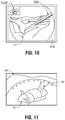
- step S120 using positional data obtained by the IR camera 514, or the optical scanning system, various feature points or fiducials are detected within the structured light scanner data, such as fissures, ligament attachments, adhesions "A,” the surface height of the patient's "P” lungs “L,” or any other suitable feature point located within the thoracic cavity ( FIG. 11 ).
- the offset of these detected feature points relative to corresponding feature points in the collapsed CLM is calculated.
- the offset of the feature points between the structured light scanner data and the CLM data may be calculated using any suitable feature matching algorithm, such as Scale-Invariant Feature Transform (SIFT), Rotation-Invariant Feature Transform (RIFT), Generalized Robust Invariant Feature (G-RIF), Speeded Up Robust Features (SURF), Principal Component Analysis SIFT (PCA-SIFT), Gradient Location-Orientation Histogram (GLOH), Gauss-SIFT, or the like.
- SIFT Scale-Invariant Feature Transform
- RIFT Rotation-Invariant Feature Transform
- G-RIF Generalized Robust Invariant Feature
- SURF Speeded Up Robust Features
- PCA-SIFT Principal Component Analysis SIFT
- GLOH Gradient Location-Orientation Histogram
- Gauss-SIFT Gauss-SIFT
- the software application uses the calculated offsets of the feature points and regenerates the CLM to more accurately reflect the observed condition of the patient's "P" collapsed lung “L.”
- the CLM can be regenerated in real time as the thoracoscope 510 is advanced within the thoracic cavity relative to the patient's "P" lung “L.”
- the software application of the synthesizer 300 monitors the location of visual landmarks, such as fissures, lesions, or the like, or may use internal landmarks such as nodules (identifiable through the use of lesion detection technology) or fiducials (not shown) that have been previously placed within the patient's "P” lung “L.”
- the software application may detect a lesion within the patient's "P” lung “L” and treat the lesion as a natural fiducial, such that critical structures within the patient's "P” lung “L” can be identified within the CLM.
- step S124 video images are captured and transmitted to the monitor associated with the computer 10 or the monitoring equipment 30 ( FIG. 1 ), providing a real time view of the patient's "P" collapsed lung “L.”
- the area of interest "AOI” and other structures inside the lung “L” are superimposed over the real-time view of the patient's "P” lungs “L” in step S126 to enable the clinician to more accurately treat the area of interest "AOI” and avoid critical structures located within the lung “L” ( FIG. 12 ).
- the area of interest "AOI” may be represented by a marker 600 ( FIG. 12 ), such as a red dot, that is superimposed on the real-time view of the patient's "P” lungs “L” such that the clinician may continuously observe the location of the area of interest "AOI” while navigating the surgical instrument 400 within the body cavity and within the patient's "P” lung “L.” It is envisioned that the marker 600 may be superimposed within the patient's "P” lungs “L,” rather than on the surface of the patient's “P” lungs “L” to more accurately depict the location of the area of interest "AOI” within the patient's "P” lungs “L.”
- step S1208 it is contemplated that as the clinician manipulates the thoracoscope 510 relative to the area of interest "AOI,” the marker 600 remains located at the area of interest "AOI.” In this manner, as the thoracoscope 510 is manipulated and the field of view of the camera 516 of the thoracoscope 510 changes, the marker 600 remains stationary within the patient's "P" lungs "L.” However, should the clinician manipulate the thoracoscope 510 such that the area of interest "AOI” is no longer within the field of view of the camera 516 of the thoracoscope, in step S130, the software application superimposes an arrow 610 or other indicator over the real-time view of the lungs “L” indicative of the direction in which the area of interest "AOI" is located relative to the field of view of the camera 516 of the thoracoscope ( FIG. 13 ). As can be appreciated, the arrow 610 can be superimposed at right, left, in, out, up, down locations within the real-time view of the
- the CLM can reflect manipulation of the lungs “L” by the clinician.
- the clinician manipulates a portion of the lungs “L” using any suitable surgical instrument 90, such as surgical forceps or the like
- the CLM may be updated to reflect the current position of the lungs “L” within the thoracic cavity.
- the location of the structures within the lungs “L” and the area of interest "AOI,” and in particular, the marker 600 ( FIG. 12 ) representing the area of interest "AOI” may be updated to reflect their true location based upon how the lungs "L” have been manipulated by the clinician.
- Surgical instruments such as the endoscopes, computing devices, and other components of system 100 described herein may also be configured to work with robotic surgical systems and what is commonly referred to as "Telesurgery.”
- Such systems employ various robotic elements to assist the surgeon and allow remote operation (or partial remote operation) of surgical instrumentation.
- Various robotic arms, gears, cams, pulleys, electric and mechanical motors, etc. may be employed for this purpose and may be designed with a robotic surgical system to assist the surgeon during the course of an operation or treatment.
- Such robotic systems may include remotely steerable systems, automatically flexible surgical systems, remotely flexible surgical systems, remotely articulating surgical systems, wireless surgical systems, modular or selectively configurable remotely operated surgical systems, etc.
- the robotic surgical systems may be employed with one or more consoles that are next to the operating theater or located in a remote location.
- one team of surgeons or nurses may prep the patient for surgery and configure the robotic surgical system with one or more of the instruments disclosed herein while another surgeon (or group of surgeons) remotely controls the instruments via the robotic surgical system.
- a highly skilled surgeon may perform multiple operations in multiple locations without leaving his/her remote console which can be both economically advantageous and a benefit to the patient or a series of patients.
- the robotic arms of the surgical system are typically coupled to a pair of master handles by a controller.
- the handles can be moved by the surgeon to produce a corresponding movement of the working ends of any type of surgical instrument (e.g., end effectors, graspers, knifes, scissors, endoscopes, etc.) which may complement the use of one or more of the embodiments described herein.
- the movement of the master handles may be scaled so that the working ends have a corresponding movement that is different, smaller or larger, than the movement performed by the operating hands of the surgeon.
- the scale factor or gearing ratio may be adjustable so that the operator can control the resolution of the working ends of the surgical instrument(s).
- the systems described herein may be positioned by the robotic system and the precise position of the endoscope transmitted to the computer to construct the 3D image of the scanned organ or operative field.
- the robotic system has the ability to autonomously scan the surgical field and construct a complete 3D model of the field to aid the surgeon in directing the robotic arms or to provide necessary 3D information for the robotic system to further conduct surgical steps autonomously.
- the robotic system may direct the camera and a structured light source separately.
- the robotic system provides the relative coordinates between respective endoscopes needed to triangulate the points in the structured light and camera views to construct a 3D surface of the operative field.
- the robotic system has a specific advantage of being able to autonomously position the structure light source onto the field of view of the camera or camera endoscope. Additionally, or alternatively, with the robot controlling the camera location (or other component location), the robot may move the camera (or other component) to expand the size of the scanned anatomy (e.g., the amount scanned) to create a larger view for the user (e.g., surgeon) without input or knowledge by the user.
- the robot may move the camera (or other component) to expand the size of the scanned anatomy (e.g., the amount scanned) to create a larger view for the user (e.g., surgeon) without input or knowledge by the user.
- the master handles may include various sensors to provide feedback to the surgeon relating to various tissue parameters or conditions, e.g., tissue resistance due to manipulation, cutting or otherwise treating, pressure by the instrument onto the tissue, tissue temperature, tissue impedance, etc. As can be appreciated, such sensors provide the surgeon with enhanced tactile feedback simulating actual operating conditions.
- the master handles may also include a variety of different actuators for delicate tissue manipulation or treatment further enhancing the surgeon's ability to mimic actual operating conditions.
- a medical work station is shown generally as work station 1100 and generally may include a plurality of robot arms 1102, 1103; a control device 1104; and an operating console 1105 coupled with control device 1104.
- Operating console 1105 may include a display device 1106, which may be set up in particular to display three-dimensional images; and manual input devices 1107, 1108, by means of which a person (not shown), for example a surgeon, may be able to telemanipulate robot arms 1102, 1103 in a first operating mode.
- Each of the robot arms 1102, 1103 may include a plurality of members, which are connected through joints, and an attaching device 1109, 1111, to which may be attached, for example, a surgical tool "ST" supporting an end effector 1120, in accordance with any one of several embodiments disclosed herein.
- Robot arms 1102, 1103 may be driven by electric drives (not shown) that are connected to control device 1104.
- Control device 1104 e.g., a computer
- Control device 1104 may be set up to activate the drives, in particular by means of a computer program, in such a way that robot arms 1102, 1103, their attaching devices 1109, 1111 and thus the surgical tool (including end effector 1120) execute a desired movement according to a movement defined by means of manual input devices 1107, 1108.
- Control device 1104 may also be set up in such a way that it regulates the movement of robot arms 1102, 1103 and/or of the drives.
- Medical work station 1100 may be configured for use on a patient "P" lying on a patient table 1112 to be treated in a minimally invasive manner by means of end effector 1120. Medical work station 1100 may also include more than two robot arms 1102, 1103, the additional robot arms likewise being connected to control device 1104 and being telemanipulatable by means of operating console 1105. A medical instrument or surgical tool (including an end effector 1120) may also be attached to the additional robot arm. Medical work station 1100 may include a database 1114, in particular coupled to with control device 1104, in which are stored, for example, pre-operative data from patient/living being "P" and/or anatomical atlases.
Landscapes
- Health & Medical Sciences (AREA)
- Life Sciences & Earth Sciences (AREA)
- Engineering & Computer Science (AREA)
- Surgery (AREA)
- General Health & Medical Sciences (AREA)
- Medical Informatics (AREA)
- Physics & Mathematics (AREA)
- Public Health (AREA)
- Biomedical Technology (AREA)
- Heart & Thoracic Surgery (AREA)
- Molecular Biology (AREA)
- Animal Behavior & Ethology (AREA)
- Veterinary Medicine (AREA)
- Nuclear Medicine, Radiotherapy & Molecular Imaging (AREA)
- Pathology (AREA)
- Biophysics (AREA)
- Radiology & Medical Imaging (AREA)
- Optics & Photonics (AREA)
- Computer Vision & Pattern Recognition (AREA)
- General Physics & Mathematics (AREA)
- Theoretical Computer Science (AREA)
- Robotics (AREA)
- Signal Processing (AREA)
- Quality & Reliability (AREA)
- Oral & Maxillofacial Surgery (AREA)
- Power Engineering (AREA)
- Artificial Intelligence (AREA)
- Physiology (AREA)
- Psychiatry (AREA)
- Human Computer Interaction (AREA)
- Computer Networks & Wireless Communication (AREA)
- Endoscopes (AREA)
Abstract
Description
- This application claims the benefit of and priority to
U.S. Provisional Patent Application No. 62/798,854 filed January 30, 2019 - As technology has advanced, surgeons have begun to replace classical open surgical techniques with minimally invasive techniques such as laparoscopic and thoracoscopic surgery in an effort to minimize trauma to surrounding tissue, reduce pain, reduce scarring, and reduce the length of time the patient is required to stay in the hospital. Minimally invasive surgery, such as the thoracoscopic approach pioneered in the mid-19th century, involves the use of small incisions (from one to several), typically no larger than 3-10mm. Originally performed using a cystoscope, advances in medical technology lead to the development of specialized instruments for use in the thoracic cavity, such as a thoracoscope, to view the anatomy within the thoracic cavity while performing the surgical procedure. In the late 20th century, Video Assisted Thoracic Surgery (VATS) was developed, which utilizes a fiber-optic endoscope to further reduce the size of the incisions required to perform the procedure and to provide clearer, more defined images of the thoracic cavity.
- Concurrently, advances in medical imaging have enabled clinicians to more accurately depict the anatomy of a patient, and therefore, more accurately identify diseases and the location of any diseased tissue. These advances have enabled clinicians to more efficiently utilize minimally invasive surgical techniques, such as the thoracoscopic approach described above. Using medical imaging, such as CT (including X-ray CT, computerized axial tomography (CAT) scan, positron emission tomography (PET), and single-photon emission CT (SPECT)), a clinician is able to accurately identify lesions or other medical conditions without the need for invasive surgeries (such as an open approach or thoracotomy). However, due to the ability of modern imaging modalities to identify ever smaller lesions, which may be submucosal and not readily identified on images captured by a thoracoscopic (e.g., not visible on the thoracoscope image), surgeons must rely upon palpating tissue with their fingers to ascertain the precise location of the lesion within the tissue. As can be appreciated, palpating tissue with fingers during minimally invasive surgery is undesirable due to the need for additional ports through which the fingers of the surgeon can pass to enable the palpating of tissue.
- To alleviate this issue, significant research and development has been focused on instruments enabling remote palpation, algorithms to identify the location of lesions within tissue, haptic feedback systems capable of notifying the surgeon when instruments are near a lesion, amongst others. However, such systems rely upon senses other than sight to identify the location of lesions in relation to surgical instruments.
- The disclosure is directed to a method of displaying an area of interest within a surgical site including modeling lungs of a patient, identifying a location of an area of interest within the model of the patient's lungs, determining a topography of a surface of the patient's lungs using a first camera, a light source, and a structured light pattern source associated with an endoscope, displaying, on a monitor associated with the endoscope, real-time images of the patient's lungs captured by a second camera associated with the endoscope, the second camera having a field of view, registering the real-time images of the patient's lungs with the model of the patient's lungs using the determined topography of the surface of the patient's lungs, and superimposing, over the real-time images of the patient's lungs, a marker indicative of the location of the area of interest within the patient's lungs, the marker remaining stationary within the patient's lungs as the field of view of the second camera changes.
- In aspects, the method may include displaying, when the area of interest is outside of the field of view of the second camera, information indicative of the direction in which the area of interest is located relative to the field of view of the second camera.
- In certain aspects, the method may include advancing the endoscope within a body cavity of a patient.
- In other aspects, modeling the lungs of the patient may include acquiring computed tomography (CT) data of the patient's lungs.
- In certain aspects, modeling the lungs of the patient may include acquiring tissue data of the patient's lungs.
- In aspects, the method may include storing a software application within a memory associated with a computer, the computer having a processor configured to execute the software application, which when executed, creates a model of the patient's lungs based on the CT data and the tissue data.
- In another aspect of the disclosure, a system for displaying an area of interest within a surgical site is provided including a computer having a processor configured to execute a software application, which when executed, creates a model of a patient's lungs and a monitor associated with the computer and an endoscope. The monitor is configured to display real-time images of the patient's lungs captured by a first camera associated with the endoscope having a field of view. The processor is configured to determine a topography of the patient's lungs, register the real-time images of the patient's lungs with the model of the patient's lungs using the determined topography of the surface of the patient's lungs, and superimpose, over the real-time images of the patient's lungs, a marker indicative of the location of the area of interest within the patient's lungs. The marker remains stationary within the patient's lungs as the field of view of the first camera changes.
- In aspects, the computer may include a memory for storing computed tomography (CT) data and tissue data associated with the patient's lungs.
- In certain aspects, the processor may be configured to display, when the area of interest is outside of the field of view of the first camera, information on the monitor indicative of the direction in which the area of interest is located relative to the field of view of the first camera.
- In other aspects, the endoscope may be configured to be advanced within a body cavity of the patient.
- In aspects, the processor may be configured to acquire computed tomography (CT) data of the patient's lungs.
- In other aspects, the computer may be configured to acquire tissue data of the patient's lungs.
- In certain aspects, the endoscope may include a second camera. In aspects, the endoscope may further include a light source. In other aspects, the endoscope may further include a structured light pattern source.
- In other aspects, the topography of the patient's lungs may be determined using the second camera, the light source, and the structured light pattern source.
- According to yet another aspect of the disclosure, a method of displaying an area of interest within a surgical site is provided including instructing a processor associated with a computer to execute a software application, which when executed, creates a model of a patient's lungs, displaying real-time images of the patient's lungs captured by a first camera associated with an endoscope on a monitor associated with the computer, the first camera having a field of view, and instructing to processor to determine a topography of the patient's lungs, register the real-time images of the patient's lungs with the model of the patient's lungs using the determined topography of the patient's lungs, and superimpose, over the real-time images of the patient's lungs, a marker indicative of the location of the area of interest within the patient's lungs, where the marker remains stationary within the patient's lungs as the field of view of the first camera changes.
- In aspects, the method may include displaying, when the area of interest is outside the field of view of the first camera, information on the monitor indicative of the direction in which the area of interest is located relative to the field of view of the first camera.
- In other aspects, determining the topography of the patient's lungs may include determining the topography of the patient's lungs using a second camera, a light source, and a structured light pattern source associated with the endoscope.
- In certain aspects, instructing the processor associated with the computer to execute the software application may include acquiring computed cosmography (CT) data and tissue date of the patient's lungs.
- Various aspects and features of the disclosure are described hereinbelow with reference to the drawings, wherein:
-
FIG. 1 is a perspective view of a system provided in accordance with the disclosure configured for modeling a lung and treating an area of interest within the lung; -
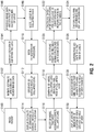
FIG. 2 is a flow chart showing a method of modeling a lung and performing a surgical procedure according to the disclosure; -
FIG. 3A is a cross-sectional view of a 3-D model of the patient's lung showing an area of interest and high and low contrast density details; -
FIG. 3B is a cross-sectional view of a 3-D model of the patient's lungs showing high and low contrast density details that have been differentiated and grouped together; -
FIG. 3C is a cross-sectional view of a 3-D model of the patient's lungs showing high and low contrast density details that have been partially differentiated; -
FIG. 4 is a cross-sectional view of a 3-D model of the patient's thoracic cavity showing the lungs and adhesions attached thereto; -
FIG. 5 is a cross-sectional view of a 3-D model of the patient's lungs showing the model having a generated mesh applied thereto; -
FIG. 6 is a cross-sectional view of a 3-D model of the patient's lungs showing the lungs in a collapsed state; -
FIG. 7 is a perspective view of a thoracoscope provided in accordance with the disclosure having a structured light scanner disposed thereon; -
FIG. 8 is a side, cross-sectional view of the patient's thoracic cavity showing the thoracoscope ofFIG. 7 advanced therein; -
FIG. 9A is an illustration of the user interface of the system ofFIG. 1 , displaying the patient's lung in a collapsed state, with a 3D model of the collapsed lung overlaid thereon; -
FIG. 9B is an illustration of the user interface of the system ofFIG. 1 , displaying the patient's lung in a collapsed state, with another 3D model of the collapsed lung overlaid thereon; -
FIG. 9C is an illustration of the user interface of the system ofFIG. 1 , displaying the patient's lung in a collapsed state, with yet another 3D model of the collapsed lung overlaid thereon; -
FIG. 10 is an illustration of the user interface of the system ofFIG. 1 , showing a camera view from the thoracoscope ofFIG. 7 ; -
FIG. 11 is an illustration of the user interface of the system ofFIG. 1 , displaying a cross-sectional view of a 3D model of the patient's thoracic cavity showing the lungs and adhesions attached thereto; -
FIG. 12 is an illustration of the user interface of the system ofFIG. 1 , showing a real-time view of the patient's lungs captured by the thoracoscope ofFIG. 7 and illustrating an area of interest indicated by a marker superimposed over the real-time view of the patient's lungs; -
FIG. 13 is an illustration of the user interface of the system ofFIG. 1 , showing a real-time view of the patient's lungs captured by the thoracoscope ofFIG. 7 and illustrating an arrow superimposed over the real-time view of the patient's lungs indicating the direction in which the area of interest is located relative to the field of view of the thoracoscope; -
FIG. 14 is an illustration of the user interface of the system ofFIG. 1 , showing the camera view from the thoracoscope ofFIG. 7 with the clinician manipulating the patient's lung; and -
FIG. 15 is a schematic illustration of a robotic surgical system configured for use in accordance with the disclosure. - The disclosure is directed to methods and systems for displaying a location of an area of interest within a surgical site. As described herein, a three-dimensional (3D) model of the patient's lungs is generated using previously obtained computed tomography (CT) data of the patient's lungs. The patient is imaged using any suitable CT device and the data is stored within a memory associated with a computer. A software application that is stored within the memory is executed by the computer to enable a clinician to review the image data. By reviewing the image data, the clinician is able to identify an area of interest indicative of lung disease and determine its location within the lungs of the patient. Once the area of interest and its location is identified by the clinician, the software application processes the image data and generates a 3D reconstruction or model of the CT images. As can be appreciated, during a thoracoscopic procedure, it is necessary to deflate a portion of the patient's lungs in order to provide the requisite space within the thoracic cavity for the surgical tools to be maneuvered. The software application is able to model the patient's lungs in a collapsed state using a segmentation algorithm to define the boundaries of various types of tissue and grouping together similar types of tissue based on their density, continuity, etc. In this manner, the accuracy of the 3D reconstruction of the patient's lungs is enhanced, enabling the clinician to develop a more accurate preoperative plan than is ordinarily possible using standard techniques.
- When beginning the surgical procedure, the clinician penetrates the patient's chest using a trocar or any other suitable access device and advances a surgical instrument, such as forceps, a surgical stapler, or the like, in addition to a second surgical tool, such as a thoracoscope, to capture real-time images of the patient's anatomy during the surgical procedure. The thoracoscope includes a structured light scanner capable of scanning a pattern on the patient's anatomy within the thoracic cavity. In addition, the thoracoscope includes an infrared (IR) camera capable of detecting IR light to detect the pattern scanned onto the patient's anatomy by the structured light scanner. Using the information gathered by the thoracoscope, the software application generates a 3D surface model of the patient's collapsed lung. In this manner, the software application is able to update the collapsed lung model and provide a more accurate model of the patient's lungs in the collapsed state. It is contemplated that the software application can display various generated 3D models of the patient's lungs to the clinician and enable the clinician to select the model that most accurately depicts the patient's lungs in the collapsed state. Additionally, rather than comparing the 3D model of the lungs to the scan obtained by the structured light scanner, it is contemplated that the 3D model may be compared to the clinician's real-time view obtained by the thoracoscope.
- Using positional data obtained by the IR camera, various feature points or fiducials are detected within the structured light scanner data, such as fissures, ligament attachments, adhesions, etc. Using this data, the 3D model can be correlated to, or registered with, the real-time view of the patient's lungs in the collapsed state. In this manner, the area of interest and other structures can be superimposed over the real-time view of the patient's lungs to enable the clinician to more accurately treat the area of interest and avoid critical structures located within the patient's lungs. The area of interest may be represented by a marker, such as a red dot, that is superimposed on the real-time view of the patient's lungs such that the clinician may continuously observe the location of the area of interest while navigating the surgical instrument within the body cavity and within the patient's lungs. In embodiments, the marker may be superimposed within the patient's lungs, rather than on its surface, to more accurately depict the location of the area of interest within the patient's lungs.
- As the clinician manipulates the thoracoscope relative to the area of interest, the marker remains located at the area of interest. In this manner, as the thoracoscope is manipulated and the field of view of the camera associated with the thoracoscope changes, the marker remains stationary within the patient's lungs. However, should the clinician manipulate the thoracoscope such that the area of interest is no longer within the field of view of the camera, the software application superimposes an arrow or other indicator over the real-time view of the patient's lungs indicative of the direction in which the area of interest is located relative to the field of view of the camera. As can be appreciated, the arrow may be superimposed at right, left, in, out, up, down locations within the real-time view of the patient's lungs.
- Although the systems and methods detailed herein are generally described with respect to the lungs, it is contemplated that the following systems and methods may be applied to the liver, spleen, or any other organ.
- Embodiments of the disclosure are now described in detail with reference to the drawings in which like reference numerals designate identical or corresponding elements in each of the several views. As used herein, the term "clinician" refers to a doctor, a nurse, or any other care provider and may include support personnel. Throughout this description, the term "proximal" will refer to the portion of the device or component thereof that is closer to the clinician and the term "distal" will refer to the portion of the device or component thereof that is farther from the clinician. Additionally, in the drawings and in the description that follows, terms such as front, rear, upper, lower, top, bottom, and similar directional terms are used simply for convenience of description and are not intended to limit the disclosure. Although generally described herein as the various determination and/or selection steps being performed by a clinician, it is contemplated that the determination and/or selection steps described herein may be performed by the software application, or a combination of clinician and software application input. As can be appreciated, in certain instances, it may be necessary for the software application to make certain determinations, whereas in other instances it may be necessary for the clinician to make certain determinations. In embodiments, the software application may make a determination and present the determination to the clinician for selection and/or confirmation. In other embodiments, it may be necessary for the software application to provide a prompt or other warning to the clinician regarding the consequences of the clinician's decision, or to provide an alternative selection to the clinician, or combinations thereof. In the following description, well-known functions or constructions are not described in detail to avoid obscuring the disclosure in unnecessary detail.
- As illustrated in
FIG. 1 , the methods described hereinbelow utilize asystem 100 including a navigation system capable of guiding asurgical tool 80 within the thoracic cavity and the patient's "P" lungs "L" to an area of interest "AOI." The navigation system includes atracking system 110 that is configured for use with thesurgical tool 80 and enables monitoring of the position and orientation of a distal portion of thesurgical tool 80. Thesystem 100 further includes acomputer 10 and auser interface 20 displayed on a display associated with thecomputer 10 or suitable monitoring equipment 30 (e.g., a video display). The role and use of thesystem 100 with the methods described herein will be described in further detail hereinbelow. - With reference to the flow chart depicted in
FIG. 2 , a method of treating a patient using a generated model of the lungs "L" of a patient "P" using computed tomography (CT) data is described. Initially, in step S100, the patient "P" is imaged using any suitable CT device (not shown), such as X-ray CT, computerized axial tomography (CAT) scan, positron emission tomography (PET), and single-photon emission CT (SPECT), and the imaging data is stored within a memory (not shown) coupled to the computer 10 (FIG. 1 ). The memory may include any non-transitory computer-readable storage media for storing data and/or software that is executable by a processor (not shown), e.g., solid-state, volatile, non-volatile, removable, and non-removable. As can be appreciated, the images may be stored within a memory associated with a remote computer or network (not shown) such as a distributed network or the internet via a wired or wireless connection for the transmission and reception of data to and from other sources. It is further contemplated that the images may be stored on one or more removable storage devices (not shown), such as optical disks, memory cards, Zip disks or Floppy Disks, Disk packs, Magnetic tapes, USB flash drives, external hard drives, amongst others. - Following imaging of the patient, in
step S 102, a software application stored within the memory is executed by a processor associated with the computer to enable review of the image data. One example of such an application is ILOGIC® planning and navigation suites currently marketed by Medtronic PLC. An area of interest ("AOI;"FIG. 5 ) illustrating the effects of lung disease (e.g., emphysema, COPD, asthma, cancer, or the like) is identified in the images and its location determined within the lungs "L" of the patient "P." Several imaging methods used for identifying an area of interest "AOI" are contemplated such as ultrasound, CT scan, metabolic scanning, amongst others. In one non-limiting embodiment, hypodense portions of the lungs "L" may be identified in the CT images which correlate to areas affected by emphysema as the expanded floppy alveoli of bulla will provide images which may be substantially darker or blacker than the surrounding tissue. In certain embodiments, a device capable of performing a combined PET/CT imaging technique may be utilized to identify hypodense areas of the lungs "L." After analysis of the image data, using one of the above-described techniques, in step S104, the location of the area of interest "AOI" within the lung "L" may be identified and its location stored within the memory coupled to the computer 10 (FIG. 1 ). - Referring to
FIG. 3A , in conjunction withFIG. 2 , in step S106, the image data obtained during step S100 is processed by the software application and a 3D reconstruction of the CT images is generated using any suitable method known in the art. As can be appreciated, during a thoracoscopic procedure such as that described hereinbelow, it is necessary to deflate a portion of the patient's lungs (e.g., induce atelectasis) in order to provide the requisite space within the thoracic cavity for the surgical tools to be maneuvered. As described hereinabove, the 3D reconstruction is necessarily a reconstruction of a fully inflated lung. Therefore, once the surgical procedure has begun, the geometry of the lungs changes leading to a shift in the location of the identified area of interest "AOI" within the lungs and thoracic cavity. Thus, the pre-operative plan that is developed as described in detail hereinbelow must compensate for the altered geometry of the lung during the surgical procedure. - To compensate for this altered geometry, in step S108, the software application models the patient's "P" lung "L" in a collapsed state. Specifically, the software application employs a segmentation algorithm to define the boundaries of various types of tissues and group together similar types of tissue based on their density and continuity, amongst other factors (
FIG. 3B ). It is contemplated that the software application may utilize any suitable segmentation algorithm, such as binary masking, determination of the optimum threshold that separates tissue and background, adaptive region growing, wavefront propagation, or the like. - As can be appreciated, the software application may not be able to differentiate all of the differing tissue types (
FIG. 3C ). As such, the software application enables selective toggling of arteries, veins, bronchi, and the like to correct any inaccuracies. In this manner, the software application presents each segmented group as a different color or different transparency level that may be selectively adjusted by the clinician in order to enable the clinician to better identify each segmented or differentiated group, or in embodiments, may present identified structures as opaque and unidentified structures as translucent, or vice versa. - To further enhance the accuracy of the reconstruction of the collapsed lung, the software application adjusts the 3D reconstruction to account for the effect of gravity (e.g., the orientation of the patient on the operating table 140) and the curvature of the patient's spine in the coronal or frontal plane (e.g., the plane dividing the patient's "P" body into ventral and dorsal sections). Other structures within the thoracic cavity affect lung volume and placement of the lungs within the patient's thoracic cavity, such as adhesions, lesion, of the like (
FIG. 4 ). The software application recognizes such structures via the previously obtained images of the patient's "P" lungs "L" and accounts for the presence of these structures by forcing the lung "L" to sit higher in the thoracic cavity, in the case of the presence of an adhesion, by fixing the adhesions to a fixed boundary at the ribcage and applying elastic models to determine displacement, or combinations thereof. In the alternative, the software application may recognize the removal of adhesions, or removal of the adhesions may be manually entered into the synthesizer by the clinician, and the software application will readjust the model accordingly (e.g., the lung "L" will sit further down towards the hilum. - It is envisioned that the software application can estimate a more likely level of lung deflation as the elastic properties of the lung tissues will be affected by common lung conditions such as COPD, the age of the patient, smoking status of the patient, etc. Additionally, the software application can take into account prior surgical procedures the patient "P" may have undergone that would impact overall lung volume. After identifying the various structures within the lung "L," the software application employs a Finite Element Analysis (FEA) algorithm to model the lung "L" and present the collapsed lung model to the clinician on the display 20 (
FIGS. 5 and6 ). The resulting 3D model of the collapsed lung forms a Computational Lung Model (CLM) that is the 3D model that is displayed to the clinician on thedisplay 20 or monitoring equipment associated with thecomputer 110 during pre-operative planning, intra-operative assistance, and post-operative review. - With reference to
FIGS. 7 and 8 , after the CLM has been developed, in step S110, the clinician may begin the desired procedure by penetrating the patient's "P" chest using a trocar (not shown) or other suitable access device through which a surgical instrument 400 (e.g., forceps, surgical stapler, electrosurgical instrument, clip applier, or the like) is advanced into the patient's "P" body cavity. As can be appreciated, a second surgical tool is advanced within the body cavity of the patient "P" to capture real-time images of the patient's anatomy during the surgical procedure. In one non-limiting embodiment, the second surgical tool is athoracoscope 510 or other suitable device, such as an endoscope or laparoscope, capable of being advanced within the thoracic cavity of a patient "P" and having a structured light scanner 512 (FIG. 7 ) disposed thereon. It is contemplated that thethoracoscope 510 may include any suitable structuredlight scanner 512 known in the art, such as a light emitting diode "LED" or LED infrared laser, or a visible light LED laser, that is disposed in a suitable manner on thethoracoscope 510 to scan a pattern (e.g., line, mesh, dots, etc.), by a rotating mirror, a beam splitter, or diffraction grating, or may be a digital light processing (DLP) projector. In one non-limiting embodiment, the structuredlight scanner 512 is an LED laser having collimated light. Thethoracoscope 510 further includes an IR camera 514 (FIG. 7 ) disposed thereon that is capable of detecting IR light. It is contemplated that theIR camera 514 may be any thermographic camera known in the art, such as ferroelectric, silicon microbolometer, uncooled focal plane array (UFPA), amongst others. It is further contemplated that the various sensors disposed on thethoracoscope 510 may be separate and distinct components with associated hardware and/or software, or may be part of a commercial platform such as Intel®'s RealSense™. Thethoracoscope 510 is a steerable thoracoscope capable of being manipulated relative to a longitudinal axis defined through proximal and distal portions of thethoracoscope 510, such that a distal portion of thethoracoscope 510 can be oriented at various angles relative to the patient's "P" lungs "L" (FIG. 8 ). As can be appreciated, a steerable thoracoscope is capable of capturing the required images of the patient's "P" lungs "L" without being removed from the patient's "P" body cavity. In contrast, if thethoracoscope 510 is a rigid thoracoscope, it may be necessary to advance the rigid thoracoscope through multiple incisions or trocars in order to take the necessary images of the patient's "P" lungs "L" to generate the 3D surface model of the patient's "P" lungs "L." - Using the information gathered by the
thoracoscope 510, in step S112, the software application generates a 3D surface model of the patient's "P" collapsed lung "L." The 3D surface model of the collapsed lung is utilized by the software application to update the CLM and provide a more accurate model of the patient's "P" lungs "L" in the collapsed state. In step S114 (FIGS. 9A-9C ), the software application displays a plurality of generated 3D surface models of the patient's lungs to the clinician via theuser interface 20. In step S116, the software application enables the clinician to select a lung deflation model that most accurately depicts the patient's "P" lung "L" in the collapsed state (FIGS. 9A-9C ). For example,FIG. 9A illustrates the CLM superimposed over the scan of the patient's lung in the collapsed state.FIG. 9B illustrates a selected CLM that most accurately matches the scan of the patient's lung in the collapsed state.FIG. 9C illustrates the clinician using hand gestures to alter the shape and rotation of the CLM to more closely match the scan of the patient's lung in the collapsed state. In embodiments, the clinician may alter the shape and rotation of the CLM in real-time. In this manner, the clinician may adjust, in real-time, the amount of inflation or deflation of the lung, adjusting the amount of rotation of the lung in the thoracic cavity in each of the X, Y, and Z axes, etc. - With reference to
FIG. 10 , it is further contemplated that, rather than comparing the CLM to the scan obtained by the structuredlight scanner 512, in step S118, the CLM may be compared to the clinician's real-time view of the patient's "P" collapsed lung "L" obtained by thethoracoscope 510. In this manner, thethoracoscope 510 includes acamera 516 or other suitable device for capturing video images disposed at a distal portion thereof. As can be appreciated, thethoracoscope 510 may be any suitable thoracoscope capable of being used during a video-assisted thoracoscopic surgical (VATS) procedure, image-guided video-assisted thoracoscopic surgical (iVATS) procedure, or robotic-assisted thoracoscopic surgical (RATS) procedure. In embodiments, thecamera 516 may be an optical scanning system (not shown), such as a digital light processing (DLP) system, that may be utilized to accurately size the patient's "P" lung "L" in the collapsed state. - In step S120, using positional data obtained by the
IR camera 514, or the optical scanning system, various feature points or fiducials are detected within the structured light scanner data, such as fissures, ligament attachments, adhesions "A," the surface height of the patient's "P" lungs "L," or any other suitable feature point located within the thoracic cavity (FIG. 11 ). Once the feature points are identified, in step S122, the offset of these detected feature points relative to corresponding feature points in the collapsed CLM is calculated. It is contemplated that the offset of the feature points between the structured light scanner data and the CLM data may be calculated using any suitable feature matching algorithm, such as Scale-Invariant Feature Transform (SIFT), Rotation-Invariant Feature Transform (RIFT), Generalized Robust Invariant Feature (G-RIF), Speeded Up Robust Features (SURF), Principal Component Analysis SIFT (PCA-SIFT), Gradient Location-Orientation Histogram (GLOH), Gauss-SIFT, or the like. The software application uses the calculated offsets of the feature points and regenerates the CLM to more accurately reflect the observed condition of the patient's "P" collapsed lung "L." As can be appreciated, the CLM can be regenerated in real time as thethoracoscope 510 is advanced within the thoracic cavity relative to the patient's "P" lung "L." In this manner, the software application of the synthesizer 300 monitors the location of visual landmarks, such as fissures, lesions, or the like, or may use internal landmarks such as nodules (identifiable through the use of lesion detection technology) or fiducials (not shown) that have been previously placed within the patient's "P" lung "L." In embodiments, the software application may detect a lesion within the patient's "P" lung "L" and treat the lesion as a natural fiducial, such that critical structures within the patient's "P" lung "L" can be identified within the CLM. - As the
thoracoscope 510 is advanced within the thoracic cavity, in step S124, video images are captured and transmitted to the monitor associated with thecomputer 10 or the monitoring equipment 30 (FIG. 1 ), providing a real time view of the patient's "P" collapsed lung "L." After correlating or registering the CLM to the real-time view of the patient's "P" collapsed lung "L" obtained by thethoracoscope 510, the area of interest "AOI" and other structures inside the lung "L" are superimposed over the real-time view of the patient's "P" lungs "L" in step S126 to enable the clinician to more accurately treat the area of interest "AOI" and avoid critical structures located within the lung "L" (FIG. 12 ). In embodiments, the area of interest "AOI" may be represented by a marker 600 (FIG. 12 ), such as a red dot, that is superimposed on the real-time view of the patient's "P" lungs "L" such that the clinician may continuously observe the location of the area of interest "AOI" while navigating thesurgical instrument 400 within the body cavity and within the patient's "P" lung "L." It is envisioned that themarker 600 may be superimposed within the patient's "P" lungs "L," rather than on the surface of the patient's "P" lungs "L" to more accurately depict the location of the area of interest "AOI" within the patient's "P" lungs "L." - In step S128, it is contemplated that as the clinician manipulates the
thoracoscope 510 relative to the area of interest "AOI," themarker 600 remains located at the area of interest "AOI." In this manner, as thethoracoscope 510 is manipulated and the field of view of thecamera 516 of the thoracoscope 510 changes, themarker 600 remains stationary within the patient's "P" lungs "L." However, should the clinician manipulate thethoracoscope 510 such that the area of interest "AOI" is no longer within the field of view of thecamera 516 of the thoracoscope, in step S130, the software application superimposes anarrow 610 or other indicator over the real-time view of the lungs "L" indicative of the direction in which the area of interest "AOI" is located relative to the field of view of thecamera 516 of the thoracoscope (FIG. 13 ). As can be appreciated, thearrow 610 can be superimposed at right, left, in, out, up, down locations within the real-time view of the lungs "L." - It is further contemplated that the CLM can reflect manipulation of the lungs "L" by the clinician. As illustrated in
FIG. 14 , as the clinician manipulates a portion of the lungs "L" using any suitable surgical instrument 90, such as surgical forceps or the like, the CLM may be updated to reflect the current position of the lungs "L" within the thoracic cavity. In this manner, the location of the structures within the lungs "L" and the area of interest "AOI," and in particular, the marker 600 (FIG. 12 ) representing the area of interest "AOI," may be updated to reflect their true location based upon how the lungs "L" have been manipulated by the clinician. - Surgical instruments such as the endoscopes, computing devices, and other components of
system 100 described herein may also be configured to work with robotic surgical systems and what is commonly referred to as "Telesurgery." Such systems employ various robotic elements to assist the surgeon and allow remote operation (or partial remote operation) of surgical instrumentation. Various robotic arms, gears, cams, pulleys, electric and mechanical motors, etc. may be employed for this purpose and may be designed with a robotic surgical system to assist the surgeon during the course of an operation or treatment. Such robotic systems may include remotely steerable systems, automatically flexible surgical systems, remotely flexible surgical systems, remotely articulating surgical systems, wireless surgical systems, modular or selectively configurable remotely operated surgical systems, etc. - The robotic surgical systems may be employed with one or more consoles that are next to the operating theater or located in a remote location. In this instance, one team of surgeons or nurses may prep the patient for surgery and configure the robotic surgical system with one or more of the instruments disclosed herein while another surgeon (or group of surgeons) remotely controls the instruments via the robotic surgical system. As can be appreciated, a highly skilled surgeon may perform multiple operations in multiple locations without leaving his/her remote console which can be both economically advantageous and a benefit to the patient or a series of patients.
- The robotic arms of the surgical system are typically coupled to a pair of master handles by a controller. The handles can be moved by the surgeon to produce a corresponding movement of the working ends of any type of surgical instrument (e.g., end effectors, graspers, knifes, scissors, endoscopes, etc.) which may complement the use of one or more of the embodiments described herein. The movement of the master handles may be scaled so that the working ends have a corresponding movement that is different, smaller or larger, than the movement performed by the operating hands of the surgeon. The scale factor or gearing ratio may be adjustable so that the operator can control the resolution of the working ends of the surgical instrument(s).
- It is contemplated that the systems described herein may be positioned by the robotic system and the precise position of the endoscope transmitted to the computer to construct the 3D image of the scanned organ or operative field. The robotic system has the ability to autonomously scan the surgical field and construct a complete 3D model of the field to aid the surgeon in directing the robotic arms or to provide necessary 3D information for the robotic system to further conduct surgical steps autonomously. In embodiments, where the endoscope includes a camera and a structured light source that are independent of one another, the robotic system may direct the camera and a structured light source separately. The robotic system provides the relative coordinates between respective endoscopes needed to triangulate the points in the structured light and camera views to construct a 3D surface of the operative field. In this manner, the robotic system has a specific advantage of being able to autonomously position the structure light source onto the field of view of the camera or camera endoscope. Additionally, or alternatively, with the robot controlling the camera location (or other component location), the robot may move the camera (or other component) to expand the size of the scanned anatomy (e.g., the amount scanned) to create a larger view for the user (e.g., surgeon) without input or knowledge by the user.
- The master handles may include various sensors to provide feedback to the surgeon relating to various tissue parameters or conditions, e.g., tissue resistance due to manipulation, cutting or otherwise treating, pressure by the instrument onto the tissue, tissue temperature, tissue impedance, etc. As can be appreciated, such sensors provide the surgeon with enhanced tactile feedback simulating actual operating conditions. The master handles may also include a variety of different actuators for delicate tissue manipulation or treatment further enhancing the surgeon's ability to mimic actual operating conditions.
- Referring to
FIG. 15 , a medical work station is shown generally aswork station 1100 and generally may include a plurality of robot arms 1102, 1103; a control device 1104; and an operating console 1105 coupled with control device 1104. Operating console 1105 may include a display device 1106, which may be set up in particular to display three-dimensional images; and manual input devices 1107, 1108, by means of which a person (not shown), for example a surgeon, may be able to telemanipulate robot arms 1102, 1103 in a first operating mode. - Each of the robot arms 1102, 1103 may include a plurality of members, which are connected through joints, and an attaching device 1109, 1111, to which may be attached, for example, a surgical tool "ST" supporting an end effector 1120, in accordance with any one of several embodiments disclosed herein.
- Robot arms 1102, 1103 may be driven by electric drives (not shown) that are connected to control device 1104. Control device 1104 (e.g., a computer) may be set up to activate the drives, in particular by means of a computer program, in such a way that robot arms 1102, 1103, their attaching devices 1109, 1111 and thus the surgical tool (including end effector 1120) execute a desired movement according to a movement defined by means of manual input devices 1107, 1108. Control device 1104 may also be set up in such a way that it regulates the movement of robot arms 1102, 1103 and/or of the drives.
-
Medical work station 1100 may be configured for use on a patient "P" lying on a patient table 1112 to be treated in a minimally invasive manner by means of end effector 1120.Medical work station 1100 may also include more than two robot arms 1102, 1103, the additional robot arms likewise being connected to control device 1104 and being telemanipulatable by means of operating console 1105. A medical instrument or surgical tool (including an end effector 1120) may also be attached to the additional robot arm.Medical work station 1100 may include a database 1114, in particular coupled to with control device 1104, in which are stored, for example, pre-operative data from patient/living being "P" and/or anatomical atlases. - While several embodiments of the disclosure have been shown in the drawings, it is not intended that the disclosure be limited thereto, as it is intended that the disclosure be as broad in scope as the art will allow and that the specification be read likewise. Therefore, the above description should not be construed as limiting, but merely as exemplifications of particular embodiments.
- The invention may be described by reference to the following numbered paragraphs:-
- 1. A method of displaying an area of interest within a surgical site, comprising:
- modeling lungs of a patient;
- identifying a location of an area of interest within the model of the patient's lungs;
- determining a topography of a surface of the patient's lungs using a first camera, a light source, and a structured light pattern source associated with an endoscope;
- displaying, on a monitor associated with the endoscope, real-time images of the patient's lungs captured by a second camera associated with the endoscope, the second camera having a field of view;
- registering the real-time images of the patient's lungs with the model of the patient's lungs using the determined topography of the surface of the patient's lungs; and
- superimposing, over the real-time images of the patient's lungs, a marker indicative of the location of the area of interest within the patient's lungs, the marker remaining stationary within the patient's lungs as the field of view of the second camera changes.
- 2. The method according to
paragraph 1, further comprising displaying, when the area of interest is outside of the field of view of the second camera, information indicative of the direction in which the area of interest is located relative to the field of view of the second camera. - 3. The method according to
paragraph 1, further comprising advancing the endoscope within a body cavity of the patient. - 4. The method according to
paragraph 1, wherein modeling the lungs of the patient includes acquiring computed tomography (CT) data of the patient's lungs. - 5. The method according to paragraph 4, wherein modeling the lungs of the patient includes acquiring tissue data of the patient's lungs.
- 6. The method according to paragraph 5, further comprising storing a software application within a memory associated with a computer, the computer having a processor configured to execute the software application, which when executed, creates a model of the patient's lungs based on the CT data and the tissue data.
- 7. A system for displaying an area of interest within a surgical site, comprising:
- a computer having a processor configured to execute a software application, which when executed, creates a model of a patient's lungs; and
- a monitor associated with the computer and an endoscope, the monitor configured to display real-time images of the patient's lungs captured by a first camera associated with the endoscope, the first camera having a field of view,
- wherein the processor is configured to determine a topography of the patient's lungs, register the real-time images of the patient's lungs with the model of the patient's lungs using the determined topography of the surface of the patient's lungs, and superimpose, over the real-time images of the patient's lungs, a marker indicative of the location of the area of interest within the patient's lungs, the marker remaining stationary within the patient's lungs as the field of view of the first camera changes.
- 8. The system according to paragraph 7, wherein the computer includes a memory for storing computed tomography (CT) data and tissue data associated with the patient's lungs.
- 9. The system according to paragraph 7, wherein the processor is configured to display, when the area of interest is outside of the field of view of the first camera, information on the monitor indicative of the direction in which the area of interest is located relative to the field of view of the first camera.
- 10. The system according to paragraph 7, wherein the endoscope is configured to be advanced within a body cavity of the patient.
- 11. The system according to paragraph 7, wherein the processor is configured to acquire computed tomography (CT) data of the patient's lungs.
- 12. The system according to paragraph 7, wherein the computer is configured to acquire tissue data of the patient's lungs.
- 13. The system according to paragraph 7, wherein the endoscope includes a second camera.
- 14. The system according to paragraph 13, wherein the endoscope includes a light source.
- 15. The system according to paragraph 14, wherein the endoscope includes a structured light pattern source.
- 16. The system according to paragraph 15, wherein the topography of the patient's lungs is determined using the second camera, the light source, and the structured light pattern source.
- 17. A method of displaying an area of interest within a surgical site, comprising:
- instructing a processor associated with a computer to execute a software application, which when executed, creates a model of a patient's lungs;
- displaying real-time images of the patient's lungs captured by a first camera associated with an endoscope on a monitor associated with the computer, the first camera having a field of view; and
- instructing the processor to:
- determine a topography of the patient's lungs;
- register the real-time images of the patient's lungs with the model of the patient's lungs using the determined topography of the patient's lungs; and
- superimpose, over the real-time images of the patient's lungs, a marker indicative of the location of the area of interest within the patient's lungs, the marker remaining stationary within the patient's lungs as the field of view of the first camera changes.
- 18. The method according to paragraph 17, further including displaying, when the area of interest is outside the field of view of the first camera, information on the monitor indicative of the direction in which the area of interest is located relative to the field of view of the first camera.
- 19. The method according to paragraph 17, wherein determining the topography of the patient's lungs includes determining the topography of the patient's lungs using a second camera, a light source, and a structured light pattern source associated with the endoscope.
- 20. The method according to paragraph 17, wherein instructing the processor associated with the computer to execute the software application includes acquiring computed tomography (CT) data and tissue data of the patient's lungs.
Claims (15)
- A method of displaying an area of interest within a surgical site, comprising:modeling lungs of a patient;identifying a location of an area of interest within the model of the patient's lungs;determining a topography of a surface of the patient's lungs using a first camera, a light source, and a structured light pattern source associated with an endoscope;displaying, on a monitor associated with the endoscope, real-time images of the patient's lungs captured by a second camera associated with the endoscope, the second camera having a field of view;registering the real-time images of the patient's lungs with the model of the patient's lungs using the determined topography of the surface of the patient's lungs; andsuperimposing, over the real-time images of the patient's lungs, a marker indicative of the location of the area of interest within the patient's lungs, the marker remaining stationary within the patient's lungs as the field of view of the second camera changes.
- The method according to claim 1, further comprising displaying, when the area of interest is outside of the field of view of the second camera, information indicative of the direction in which the area of interest is located relative to the field of view of the second camera; and/or further comprising advancing the endoscope within a body cavity of the patient.
- The method according to claim 1 or claim 2, wherein modeling the lungs of the patient includes acquiring computed tomography (CT) data of the patient's lungs; preferably wherein modeling the lungs of the patient includes acquiring tissue data of the patient's lungs.
- The method according to claim 3, further comprising storing a software application within a memory associated with a computer, the computer having a processor configured to execute the software application, which when executed, creates a model of the patient's lungs based on the CT data and the tissue data.
- A system for displaying an area of interest within a surgical site, comprising:a computer having a processor configured to execute a software application, which when executed, creates a model of a patient's lungs; anda monitor associated with the computer and an endoscope, the monitor configured to display real-time images of the patient's lungs captured by a first camera associated with the endoscope, the first camera having a field of view,wherein the processor is configured to determine a topography of the patient's lungs, register the real-time images of the patient's lungs with the model of the patient's lungs using the determined topography of the surface of the patient's lungs, and superimpose, over the real-time images of the patient's lungs, a marker indicative of the location of the area of interest within the patient's lungs, the marker remaining stationary within the patient's lungs as the field of view of the first camera changes.
- The system according to claim 5, wherein the computer includes a memory for storing computed tomography (CT) data and tissue data associated with the patient's lungs; and/or wherein the processor is configured to display, when the area of interest is outside of the field of view of the first camera, information on the monitor indicative of the direction in which the area of interest is located relative to the field of view of the first camera.
- The system according to claim 5 or claim 6, wherein the endoscope is configured to be advanced within a body cavity of the patient.
- The system according to any of claims 5 to 7, wherein the processor is configured to acquire computed tomography (CT) data of the patient's lungs.
- The system according to any of claims 5 to 8, wherein the computer is configured to acquire tissue data of the patient's lungs.
- The system according to any of claims 5 to 9, wherein the endoscope includes a second camera; preferably, wherein the endoscope includes a light source.
- The system according to claim 10, wherein the endoscope includes a structured light pattern source.
- The system according to claim 11, wherein the topography of the patient's lungs is determined using the second camera, the light source, and the structured light pattern source.
- A method of displaying an area of interest within a surgical site, comprising:instructing a processor associated with a computer to execute a software application, which when executed, creates a model of a patient's lungs;displaying real-time images of the patient's lungs captured by a first camera associated with an endoscope on a monitor associated with the computer, the first camera having a field of view; andinstructing the processor to:determine a topography of the patient's lungs;register the real-time images of the patient's lungs with the model of the patient's lungs using the determined topography of the patient's lungs; andsuperimpose, over the real-time images of the patient's lungs, a marker indicative of the location of the area of interest within the patient's lungs, the marker remaining stationary within the patient's lungs as the field of view of the first camera changes.
- The method according to claim 13, further including displaying, when the area of interest is outside the field of view of the first camera, information on the monitor indicative of the direction in which the area of interest is located relative to the field of view of the first camera.
- The method according to claim 13 or claim 14, wherein determining the topography of the patient's lungs includes determining the topography of the patient's lungs using a second camera, a light source, and a structured light pattern source associated with the endoscope; and/or wherein instructing the processor associated with the computer to execute the software application includes acquiring computed tomography (CT) data and tissue data of the patient's lungs.
Applications Claiming Priority (2)
| Application Number | Priority Date | Filing Date | Title |
|---|---|---|---|
| US201962798854P | 2019-01-30 | 2019-01-30 | |
| US16/718,815 US11625825B2 (en) | 2019-01-30 | 2019-12-18 | Method for displaying tumor location within endoscopic images |
Publications (2)
| Publication Number | Publication Date |
|---|---|
| EP3690810A1 true EP3690810A1 (en) | 2020-08-05 |
| EP3690810B1 EP3690810B1 (en) | 2022-06-15 |
Family
ID=69400368
Family Applications (1)
| Application Number | Title | Priority Date | Filing Date |
|---|---|---|---|
| EP20154253.7A Active EP3690810B1 (en) | 2019-01-30 | 2020-01-29 | Method for displaying tumor location within endoscopic images |
Country Status (3)
| Country | Link |
|---|---|
| US (1) | US11625825B2 (en) |
| EP (1) | EP3690810B1 (en) |
| CN (1) | CN111494006B (en) |
Cited By (1)
| Publication number | Priority date | Publication date | Assignee | Title |
|---|---|---|---|---|
| CN114343873A (en) * | 2022-01-07 | 2022-04-15 | 苏州康多机器人有限公司 | An endoscopic surgery monitoring system and method |
Families Citing this family (9)
| Publication number | Priority date | Publication date | Assignee | Title |
|---|---|---|---|---|
| JP7376677B2 (en) * | 2020-02-21 | 2023-11-08 | オリンパス株式会社 | Image processing system, endoscope system and method of operating the endoscope system |
| US12465429B2 (en) * | 2020-10-09 | 2025-11-11 | Smith & Nephew, Inc. | Markerless navigation system |
| JP7124041B2 (en) * | 2020-11-25 | 2022-08-23 | 株式会社朋 | Program for pointing out Hanna's lesions |
| US12605039B2 (en) | 2021-12-03 | 2026-04-21 | Ambu A/S | Endoscope image processing device |
| US12525145B2 (en) | 2021-12-03 | 2026-01-13 | Ambu A/S | Endoscopic training system |
| KR102667467B1 (en) * | 2021-12-13 | 2024-05-20 | (주)휴톰 | Apparatus and Method for Providing a Virtual Reality-based Surgical Environment Using a Patient's Virtual Lung Model |
| CN114066781B (en) * | 2022-01-18 | 2022-05-10 | 浙江鸿禾医疗科技有限责任公司 | Recognition and positioning method, storage medium and equipment for intestinal images of capsule endoscopy |
| US20250173923A1 (en) * | 2022-02-01 | 2025-05-29 | Nec Corporation | Image processing device, image processing method, and storage medium |
| CN114299072B (en) * | 2022-03-11 | 2022-06-07 | 四川大学华西医院 | Artificial intelligence-based anatomy variation identification prompting method and system |
Citations (1)
| Publication number | Priority date | Publication date | Assignee | Title |
|---|---|---|---|---|
| EP3398552A1 (en) * | 2017-05-03 | 2018-11-07 | Covidien LP | Medical image viewer control from surgeon's camera |
Family Cites Families (233)
| Publication number | Priority date | Publication date | Assignee | Title |
|---|---|---|---|---|
| US5318024A (en) | 1985-03-22 | 1994-06-07 | Massachusetts Institute Of Technology | Laser endoscope for spectroscopic imaging |
| US4932412A (en) | 1986-12-18 | 1990-06-12 | Immunomedics, Inc. | Intraoperative and endoscopic tumor detection and therapy |
| US5057494A (en) | 1988-08-03 | 1991-10-15 | Ethicon, Inc. | Method for preventing tissue damage after an ischemic episode |
| US5697885A (en) | 1989-01-30 | 1997-12-16 | Olympus Optical Co., Ltd. | Endoscope for recording and displaying time-serial images |
| ATE194916T1 (en) | 1992-05-06 | 2000-08-15 | Immunomedics Inc | INTRAOPERATIVE, INTRAVASCULAR AND ENDOSCOPIC DETERMINATION AND TREATMENT OF INJURIES AND TUMORS |
| US6096289A (en) | 1992-05-06 | 2000-08-01 | Immunomedics, Inc. | Intraoperative, intravascular, and endoscopic tumor and lesion detection, biopsy and therapy |
| US5321113A (en) | 1993-05-14 | 1994-06-14 | Ethicon, Inc. | Copolymers of an aromatic anhydride and aliphatic ester |
| DE4443947B4 (en) | 1994-01-14 | 2005-09-22 | Siemens Ag | endoscope |
| US5590660A (en) | 1994-03-28 | 1997-01-07 | Xillix Technologies Corp. | Apparatus and method for imaging diseased tissue using integrated autofluorescence |
| US7179222B2 (en) | 1996-11-20 | 2007-02-20 | Olympus Corporation | Fluorescent endoscope system enabling simultaneous achievement of normal light observation based on reflected light and fluorescence observation based on light with wavelengths in infrared spectrum |
| US6293911B1 (en) | 1996-11-20 | 2001-09-25 | Olympus Optical Co., Ltd. | Fluorescent endoscope system enabling simultaneous normal light observation and fluorescence observation in infrared spectrum |
| JP3532368B2 (en) | 1996-12-10 | 2004-05-31 | 富士写真フイルム株式会社 | Endoscope |
| US6346940B1 (en) | 1997-02-27 | 2002-02-12 | Kabushiki Kaisha Toshiba | Virtualized endoscope system |
| US5984861A (en) | 1997-09-29 | 1999-11-16 | Boston Scientific Corporation | Endofluorescence imaging module for an endoscope |
| DE69938493T2 (en) | 1998-01-26 | 2009-05-20 | Massachusetts Institute Of Technology, Cambridge | ENDOSCOPE FOR DETECTING FLUORESCENCE IMAGES |
| IL123073A0 (en) | 1998-01-26 | 1998-09-24 | Simbionix Ltd | Endoscopic tutorial system |
| US6003517A (en) | 1998-04-30 | 1999-12-21 | Ethicon Endo-Surgery, Inc. | Method for using an electrosurgical device on lung tissue |
| US6652836B2 (en) | 1998-10-15 | 2003-11-25 | Fluoroprobe, Inc. | Method for viewing tumor tissue located within a body cavity |
| US6284223B1 (en) | 1998-10-15 | 2001-09-04 | Fluoroprobe, Inc. | Method for viewing tumor tissue located within a body cavity |
| US6608081B2 (en) | 1999-08-12 | 2003-08-19 | Ortho-Mcneil Pharmaceutical, Inc. | Bicyclic heterocyclic substituted phenyl oxazolidinone antibacterials, and related compositions and methods |
| US6413981B1 (en) | 1999-08-12 | 2002-07-02 | Ortho-Mcneil Pharamceutical, Inc. | Bicyclic heterocyclic substituted phenyl oxazolidinone antibacterials, and related compositions and methods |
| JP2001061764A (en) | 1999-08-25 | 2001-03-13 | Asahi Optical Co Ltd | Endoscope device |
| US6750034B1 (en) | 2000-06-30 | 2004-06-15 | Ortho-Mcneil Pharmaceutical, Inc. | DNA encoding human serine protease D-G |
| CA2421638A1 (en) | 2000-09-11 | 2002-03-21 | Closure Medical Corporation | Bronchial occlusion method and apparatus |
| US6472372B1 (en) | 2000-12-06 | 2002-10-29 | Ortho-Mcneil Pharmaceuticals, Inc. | 6-O-Carbamoyl ketolide antibacterials |
| US6871086B2 (en) | 2001-02-15 | 2005-03-22 | Robin Medical Inc. | Endoscopic examining apparatus particularly useful in MRI, a probe useful in such apparatus, and a method of making such probe |
| EP1407004B1 (en) | 2001-05-15 | 2009-08-05 | Ortho-McNeil-Janssen Pharmaceuticals, Inc. | Ex-vivo priming for generating cd40-ligand specific cytotoxic t lymphocytes to treat autoimmune and allergic disease |
| US7172553B2 (en) | 2001-05-16 | 2007-02-06 | Olympus Corporation | Endoscope system using normal light and fluorescence |
| US20030013972A1 (en) | 2001-05-29 | 2003-01-16 | Makin Inder Raj. S. | Treatment of lung lesions using ultrasound |
| US7607440B2 (en) | 2001-06-07 | 2009-10-27 | Intuitive Surgical, Inc. | Methods and apparatus for surgical planning |
| US20060241496A1 (en) | 2002-01-15 | 2006-10-26 | Xillix Technologies Corp. | Filter for use with imaging endoscopes |
| MXPA03006874A (en) | 2002-07-31 | 2004-09-03 | Johnson & Johnson | Long term oxygen therapy system. |
| US20040120981A1 (en) | 2002-12-20 | 2004-06-24 | Aruna Nathan | Crosslinked alkyd polyesters for medical applications |
| US6984211B2 (en) | 2003-01-03 | 2006-01-10 | Mayo Foundation For Medical Education And Research | Detection of tumor halos in ultrasound images |
| US7381183B2 (en) | 2003-04-21 | 2008-06-03 | Karl Storz Development Corp. | Method for capturing and displaying endoscopic maps |
| JP2007525946A (en) | 2003-04-30 | 2007-09-13 | セントカー・インコーポレーテツド | CNGH0010-specific polynucleotides, polypeptides, antibodies, compositions, methods and uses |
| KR20060029276A (en) | 2003-07-04 | 2006-04-05 | 존슨 앤드 존슨 리서치 피티와이 리미티드 | Method for detecting alkylated cytosine in DNA |
| US7822461B2 (en) | 2003-07-11 | 2010-10-26 | Siemens Medical Solutions Usa, Inc. | System and method for endoscopic path planning |
| US8403828B2 (en) | 2003-07-21 | 2013-03-26 | Vanderbilt University | Ophthalmic orbital surgery apparatus and method and image-guide navigation system |
| EP2316328B1 (en) | 2003-09-15 | 2012-05-09 | Super Dimension Ltd. | Wrap-around holding device for use with bronchoscopes |
| DE10349649B3 (en) | 2003-10-17 | 2005-05-19 | Karl Storz Gmbh & Co. Kg | A method and apparatus for generating an annotated image in a sterile work area of a medical facility |
| WO2005058137A2 (en) | 2003-12-12 | 2005-06-30 | University Of Washington | Catheterscope 3d guidance and interface system |
| CA2587909C (en) | 2004-11-16 | 2016-01-05 | Robert L. Barry | Device and method for lung treatment |
| WO2006060653A2 (en) | 2004-11-30 | 2006-06-08 | Veridex Llc | Lung cancer prognostics |
| US8872906B2 (en) | 2005-01-05 | 2014-10-28 | Avantis Medical Systems, Inc. | Endoscope assembly with a polarizing filter |
| US8289381B2 (en) | 2005-01-05 | 2012-10-16 | Avantis Medical Systems, Inc. | Endoscope with an imaging catheter assembly and method of configuring an endoscope |
| JP4709579B2 (en) | 2005-04-26 | 2011-06-22 | オリンパスメディカルシステムズ株式会社 | Capsule endoscope |
| WO2007087421A2 (en) | 2006-01-23 | 2007-08-02 | Avantis Medical Systems, Inc. | Endoscope |
| US9055906B2 (en) | 2006-06-14 | 2015-06-16 | Intuitive Surgical Operations, Inc. | In-vivo visualization systems |
| US11389235B2 (en) | 2006-07-14 | 2022-07-19 | Neuwave Medical, Inc. | Energy delivery systems and uses thereof |
| US8498695B2 (en) | 2006-12-22 | 2013-07-30 | Novadaq Technologies Inc. | Imaging system with a single color image sensor for simultaneous fluorescence and color video endoscopy |
| US8672836B2 (en) | 2007-01-31 | 2014-03-18 | The Penn State Research Foundation | Method and apparatus for continuous guidance of endoscopy |
| JP5137033B2 (en) | 2007-01-31 | 2013-02-06 | 国立大学法人浜松医科大学 | Surgery support information display device, surgery support information display method, and surgery support information display program |
| US7655004B2 (en) | 2007-02-15 | 2010-02-02 | Ethicon Endo-Surgery, Inc. | Electroporation ablation apparatus, system, and method |
| DE102007029888B4 (en) | 2007-06-28 | 2016-04-07 | Siemens Aktiengesellschaft | Medical diagnostic imaging and apparatus operating according to this method |
| US8335359B2 (en) | 2007-07-20 | 2012-12-18 | General Electric Company | Systems, apparatus and processes for automated medical image segmentation |
| FR2920085B1 (en) | 2007-08-24 | 2012-06-15 | Univ Grenoble 1 | IMAGING SYSTEM FOR THREE-DIMENSIONAL OBSERVATION OF AN OPERATIVE FIELD |
| US8323182B2 (en) | 2007-12-18 | 2012-12-04 | Manohara Harish M | Endoscope and system and method of operation thereof |
| US8169468B2 (en) | 2008-04-26 | 2012-05-01 | Intuitive Surgical Operations, Inc. | Augmented stereoscopic visualization for a surgical robot |
| US8218847B2 (en) | 2008-06-06 | 2012-07-10 | Superdimension, Ltd. | Hybrid registration method |
| SE532644C2 (en) | 2008-07-03 | 2010-03-09 | Aamic Ab | Procedure for analyzing circulating antibodies |
| US10092169B2 (en) | 2008-07-08 | 2018-10-09 | Karl Storz Imaging, Inc. | Solid state variable direction of view endoscope |
| US8758234B2 (en) | 2008-07-08 | 2014-06-24 | Karl Storz Imaging, Inc. | Solid state variable direction of view endoscope |
| US8771177B2 (en) | 2008-07-08 | 2014-07-08 | Karl Storz Imaging, Inc. | Wide angle flexible endoscope |
| US8814782B2 (en) | 2008-07-08 | 2014-08-26 | Karl Storz Imaging, Inc. | Solid state variable direction of view endoscope |
| EP2335560B1 (en) | 2008-10-17 | 2014-11-26 | Olympus Medical Systems Corp. | Endoscope system and endoscopic image processing apparatus |
| JP2010113312A (en) | 2008-11-10 | 2010-05-20 | Hoya Corp | Endoscope apparatus and endoscope processor |
| US8361066B2 (en) | 2009-01-12 | 2013-01-29 | Ethicon Endo-Surgery, Inc. | Electrical ablation devices |
| US20180009767A9 (en) | 2009-03-19 | 2018-01-11 | The Johns Hopkins University | Psma targeted fluorescent agents for image guided surgery |
| US8337397B2 (en) | 2009-03-26 | 2012-12-25 | Intuitive Surgical Operations, Inc. | Method and system for providing visual guidance to an operator for steering a tip of an endoscopic device toward one or more landmarks in a patient |
| US10004387B2 (en) | 2009-03-26 | 2018-06-26 | Intuitive Surgical Operations, Inc. | Method and system for assisting an operator in endoscopic navigation |
| US10492671B2 (en) | 2009-05-08 | 2019-12-03 | Novadaq Technologies ULC | Near infra red fluorescence imaging for visualization of blood vessels during endoscopic harvest |
| JP5395538B2 (en) | 2009-06-30 | 2014-01-22 | 株式会社東芝 | Ultrasonic diagnostic apparatus and image data display control program |
| US8706184B2 (en) | 2009-10-07 | 2014-04-22 | Intuitive Surgical Operations, Inc. | Methods and apparatus for displaying enhanced imaging data on a clinical image |
| JP5421828B2 (en) | 2010-03-17 | 2014-02-19 | 富士フイルム株式会社 | Endoscope observation support system, endoscope observation support device, operation method thereof, and program |
| JP5551955B2 (en) | 2010-03-31 | 2014-07-16 | 富士フイルム株式会社 | Projection image generation apparatus, method, and program |
| JP5380348B2 (en) | 2010-03-31 | 2014-01-08 | 富士フイルム株式会社 | System, method, apparatus, and program for supporting endoscopic observation |
| JP5535725B2 (en) | 2010-03-31 | 2014-07-02 | 富士フイルム株式会社 | Endoscope observation support system, endoscope observation support device, operation method thereof, and program |
| JP6153865B2 (en) | 2010-05-03 | 2017-06-28 | ニューウェーブ メディカル, インコーポレイテッドNeuwave Medical, Inc. | Energy delivery system |
| JP5634755B2 (en) | 2010-06-08 | 2014-12-03 | 富士フイルム株式会社 | Electronic endoscope system, processor device for electronic endoscope, and method for operating electronic endoscope system |
| JP5460488B2 (en) | 2010-06-29 | 2014-04-02 | 富士フイルム株式会社 | Electronic endoscope system, processor device for electronic endoscope, image retrieval system, and method of operating electronic endoscope system |
| US9560953B2 (en) | 2010-09-20 | 2017-02-07 | Endochoice, Inc. | Operational interface in a multi-viewing element endoscope |
| JP5496075B2 (en) | 2010-12-27 | 2014-05-21 | 富士フイルム株式会社 | Endoscopic diagnosis device |
| JP5269921B2 (en) | 2011-01-24 | 2013-08-21 | 富士フイルム株式会社 | Electronic endoscope system and method for operating electronic endoscope system |
| EP2672915A1 (en) | 2011-02-11 | 2013-12-18 | Olaf Christiansen | Endoscopic image processing system having means which generate geometric measurement information in the detection range of an optical digital camera |
| KR20120097828A (en) | 2011-02-25 | 2012-09-05 | 삼성전자주식회사 | Endoscope apparatus capable of providing narrow band imaging and image processing method of the endoscope |
| US8900131B2 (en) | 2011-05-13 | 2014-12-02 | Intuitive Surgical Operations, Inc. | Medical system providing dynamic registration of a model of an anatomical structure for image-guided surgery |
| US8827934B2 (en) | 2011-05-13 | 2014-09-09 | Intuitive Surgical Operations, Inc. | Method and system for determining information of extrema during expansion and contraction cycles of an object |
| CN103501681B (en) | 2011-09-20 | 2015-11-25 | 奥林巴斯医疗株式会社 | Image processing device and endoscope system |
| US20130303944A1 (en) | 2012-05-14 | 2013-11-14 | Intuitive Surgical Operations, Inc. | Off-axis electromagnetic sensor |
| EP2809249B1 (en) | 2012-02-03 | 2018-12-26 | Intuitive Surgical Operations, Inc. | Steerable flexible needle with embedded shape sensing |
| KR102171520B1 (en) | 2012-05-14 | 2020-10-29 | 인튜어티브 서지컬 오퍼레이션즈 인코포레이티드 | Systems and methods for deformation compensation using shape sensing |
| US20130303945A1 (en) | 2012-05-14 | 2013-11-14 | Intuitive Surgical Operations, Inc. | Electromagnetic tip sensor |
| EP3524184B1 (en) | 2012-05-14 | 2021-02-24 | Intuitive Surgical Operations Inc. | Systems for registration of a medical device using a reduced search space |
| EP2849668B1 (en) | 2012-05-14 | 2018-11-14 | Intuitive Surgical Operations Inc. | Systems and methods for registration of a medical device using rapid pose search |
| US10039473B2 (en) | 2012-05-14 | 2018-08-07 | Intuitive Surgical Operations, Inc. | Systems and methods for navigation based on ordered sensor records |
| US9429696B2 (en) | 2012-06-25 | 2016-08-30 | Intuitive Surgical Operations, Inc. | Systems and methods for reducing measurement error in optical fiber shape sensors |
| US9763563B2 (en) | 2012-07-11 | 2017-09-19 | Karl Storz Imaging, Inc. | Endoscopic camera single-button mode activation |
| US9801551B2 (en) | 2012-07-20 | 2017-10-31 | Intuitive Sugical Operations, Inc. | Annular vision system |
| JP6074587B2 (en) | 2012-08-06 | 2017-02-08 | 株式会社Joled | Display panel, display device and electronic device |
| CN106562757B (en) | 2012-08-14 | 2019-05-14 | 直观外科手术操作公司 | The system and method for registration for multiple vision systems |
| EP2906133B1 (en) | 2012-10-12 | 2022-03-23 | Intuitive Surgical Operations, Inc. | Determining position of medical device in branched anatomical structure |
| CN104114077B (en) | 2012-10-18 | 2016-07-20 | 奥林巴斯株式会社 | Image processing device and image processing method |
| JP6008700B2 (en) | 2012-11-08 | 2016-10-19 | 富士フイルム株式会社 | Endoscope system |
| JP6034668B2 (en) | 2012-11-08 | 2016-11-30 | 富士フイルム株式会社 | Endoscope system |
| JP5947707B2 (en) | 2012-12-27 | 2016-07-06 | 富士フイルム株式会社 | Virtual endoscopic image display apparatus and method, and program |
| US20140188440A1 (en) | 2012-12-31 | 2014-07-03 | Intuitive Surgical Operations, Inc. | Systems And Methods For Interventional Procedure Planning |
| US9386908B2 (en) | 2013-01-29 | 2016-07-12 | Gyrus Acmi, Inc. (D.B.A. Olympus Surgical Technologies America) | Navigation using a pre-acquired image |
| JP6363165B2 (en) | 2013-03-15 | 2018-07-25 | インテュイティブ サージカル オペレーションズ, インコーポレイテッド | Shape sensor system for tracking interventional instruments and method of using the system |
| JP5750669B2 (en) | 2013-03-19 | 2015-07-22 | オリンパス株式会社 | Endoscope system |
| EP2981205A4 (en) | 2013-04-04 | 2017-02-15 | Children's National Medical Center | Device and method for generating composite images for endoscopic surgery of moving and deformable anatomy |
| US10499794B2 (en) | 2013-05-09 | 2019-12-10 | Endochoice, Inc. | Operational interface in a multi-viewing element endoscope |
| US9510739B2 (en) | 2013-07-12 | 2016-12-06 | Gyrus Acmi, Inc. | Endoscope small imaging system |
| CN114343608B (en) | 2013-07-29 | 2024-07-26 | 直观外科手术操作公司 | Shape sensor system with redundant sensing |
| KR102356881B1 (en) | 2013-08-15 | 2022-02-03 | 인튜어티브 서지컬 오퍼레이션즈 인코포레이티드 | Graphical user interface for catheter positioning and insertion |
| CN105473098B (en) | 2013-08-15 | 2019-03-26 | 直观外科手术操作公司 | System and method for medical procedure validation |
| WO2015054243A1 (en) | 2013-10-07 | 2015-04-16 | Van Dam, Jacques | Integrated ultrasound, oct, pa and/or florescence imaging endoscope for diagnosing cancers in gastrointestinal, respiratory, and urogenital tracts |
| CN105939647B (en) | 2013-10-24 | 2020-01-21 | 奥瑞斯健康公司 | Robot-assisted endovascular surgery system and related methods |
| KR102337440B1 (en) | 2013-12-09 | 2021-12-10 | 인튜어티브 서지컬 오퍼레이션즈 인코포레이티드 | Systems and methods for device-aware flexible tool registration |
| AU2015204201B2 (en) | 2014-01-06 | 2019-11-28 | Body Vision Medical Ltd. | Surgical devices and methods of use thereof |
| CN106170265B (en) | 2014-02-04 | 2020-06-30 | 直观外科手术操作公司 | System and method for non-rigid deformation of tissue for virtual navigation of interventional tools |
| CN105979900B (en) * | 2014-02-04 | 2020-06-26 | 皇家飞利浦有限公司 | Visualization of vessel depth and location and robot-guided visualization of vessel cross-sections |
| US20150223765A1 (en) | 2014-02-07 | 2015-08-13 | Intuitive Surgical Operations, Inc. | Systems and methods for using x-ray field emission to determine instrument position and orientation |
| DE102014203097A1 (en) | 2014-02-20 | 2015-08-20 | Siemens Aktiengesellschaft | A method of assisting navigation of an endoscopic device |
| WO2015132778A1 (en) | 2014-03-02 | 2015-09-11 | Avishay Sidlesky | Endoscopic measurement system and method |
| KR102521043B1 (en) | 2014-03-17 | 2023-04-14 | 인튜어티브 서지컬 오퍼레이션즈 인코포레이티드 | Surgical system including a non-white light general illuminator |
| US10912523B2 (en) | 2014-03-24 | 2021-02-09 | Intuitive Surgical Operations, Inc. | Systems and methods for anatomic motion compensation |
| CN106535812B (en) | 2014-03-28 | 2020-01-21 | 直观外科手术操作公司 | Surgical system with haptic feedback based on quantitative 3D imaging |
| WO2015151098A2 (en) * | 2014-04-02 | 2015-10-08 | M.S.T. Medical Surgery Technologies Ltd. | An articulated structured light based-laparoscope |
| AU2015290043B2 (en) | 2014-07-18 | 2019-08-22 | Ethicon, Inc. | Methods and devices for controlling the size of emphysematous bullae |
| ES2797748T3 (en) | 2014-07-18 | 2020-12-03 | Ethicon Inc | Mechanical retraction by anchoring to reduce lung volume |
| EP3174490B1 (en) | 2014-07-28 | 2020-04-15 | Intuitive Surgical Operations, Inc. | Systems and methods for planning multiple interventional procedures |
| KR20220065894A (en) | 2014-07-28 | 2022-05-20 | 인튜어티브 서지컬 오퍼레이션즈 인코포레이티드 | Systems and methods for intraoperative segmentation |
| KR102542848B1 (en) | 2014-08-23 | 2023-06-14 | 인튜어티브 서지컬 오퍼레이션즈 인코포레이티드 | Systems and methods for display of pathological data in an image guided procedure |
| US10373719B2 (en) | 2014-09-10 | 2019-08-06 | Intuitive Surgical Operations, Inc. | Systems and methods for pre-operative modeling |
| US10314513B2 (en) | 2014-10-10 | 2019-06-11 | Intuitive Surgical Operations, Inc. | Systems and methods for reducing measurement error using optical fiber shape sensors |
| EP3206556B1 (en) | 2014-10-17 | 2026-03-25 | Intuitive Surgical Operations, Inc. | Systems and methods for reducing measurement error using optical fiber shape sensors |
| CA2965091A1 (en) | 2014-10-20 | 2016-05-06 | Dorian Averbuch | Surgical devices and methods of use thereof |
| JP6519144B2 (en) | 2014-11-06 | 2019-05-29 | ソニー株式会社 | Endoscope system, image processing apparatus, image processing method, and program |
| CN107111684A (en) | 2014-11-13 | 2017-08-29 | 直观外科手术操作公司 | System and method for filtering localization data |
| WO2016084608A1 (en) | 2014-11-25 | 2016-06-02 | ソニー株式会社 | Endoscope system, method for operating endoscope system, and program |
| WO2016106114A1 (en) | 2014-12-22 | 2016-06-30 | Intuitive Surgical Operations, Inc. | Flexible electromagnetic sensor |
| DE102015202605B4 (en) | 2015-02-12 | 2017-03-09 | Carl Zeiss Meditec Ag | visualization system |
| US10390718B2 (en) * | 2015-03-20 | 2019-08-27 | East Carolina University | Multi-spectral physiologic visualization (MSPV) using laser imaging methods and systems for blood flow and perfusion imaging and quantification in an endoscopic design |
| EP3280312A4 (en) | 2015-04-06 | 2019-02-20 | Intuitive Surgical Operations Inc. | SYSTEMS AND METHODS FOR IMAGE-GUIDED SURGICAL RECORDING COMPENSATION |
| CN107660134B (en) | 2015-05-22 | 2021-06-29 | 直观外科手术操作公司 | System and method for image-guided surgical recording |
| WO2017030913A2 (en) | 2015-08-14 | 2017-02-23 | Intuitive Surgical Operations, Inc. | Systems and methods of registration for image-guided surgery |
| WO2017030915A1 (en) | 2015-08-14 | 2017-02-23 | Intuitive Surgical Operations, Inc. | Systems and methods of registration for image-guided surgery |
| US10245034B2 (en) | 2015-08-31 | 2019-04-02 | Ethicon Llc | Inducing tissue adhesions using surgical adjuncts and medicants |
| US10569071B2 (en) | 2015-08-31 | 2020-02-25 | Ethicon Llc | Medicant eluting adjuncts and methods of using medicant eluting adjuncts |
| CN108024693B (en) | 2015-09-10 | 2021-07-09 | 直观外科手术操作公司 | Systems and methods for utilizing tracking in image-guided medical procedures |
| EP3405908B1 (en) | 2015-09-10 | 2021-12-15 | Magentiq Eye Ltd. | A system and method for detection of suspicious tissue regions in an endoscopic procedure |
| JP6594133B2 (en) | 2015-09-16 | 2019-10-23 | 富士フイルム株式会社 | Endoscope position specifying device, operation method of endoscope position specifying device, and endoscope position specifying program |
| AU2016323982A1 (en) | 2015-09-18 | 2018-04-12 | Auris Health, Inc. | Navigation of tubular networks |
| JP6420492B2 (en) | 2015-09-28 | 2018-11-07 | 富士フイルム株式会社 | Image processing apparatus, endoscope system, and method of operating image processing apparatus |
| WO2017057572A1 (en) | 2015-09-29 | 2017-04-06 | 富士フイルム株式会社 | Image processing device, endoscopic system, and image processing method |
| JP6633641B2 (en) | 2015-09-29 | 2020-01-22 | 富士フイルム株式会社 | Image processing apparatus, endoscope system, and image processing method |
| WO2017055412A1 (en) | 2015-09-30 | 2017-04-06 | Siemens Healthcare Gmbh | Method and system for classification of endoscopic images using deep decision networks |
| WO2017075067A1 (en) | 2015-10-26 | 2017-05-04 | Neuwave Medical, Inc. | Energy delivery systems and uses thereof |
| US10405753B2 (en) | 2015-11-10 | 2019-09-10 | Intuitive Surgical Operations, Inc. | Pharmaceutical compositions of near IR closed chain, sulfo-cyanine dyes |
| EP3391030B1 (en) | 2015-12-14 | 2025-02-12 | Intuitive Surgical Operations, Inc. | Apparatus and method for generating 3-d data for an anatomical target using optical fiber shape sensing |
| US9996361B2 (en) | 2015-12-23 | 2018-06-12 | Intel Corporation | Byte and nibble sort instructions that produce sorted destination register and destination index mapping |
| JP6764574B2 (en) | 2016-01-13 | 2020-10-07 | ソニー株式会社 | Image processing equipment, image processing methods, programs, and surgical systems |
| US11399895B2 (en) | 2016-02-12 | 2022-08-02 | Intuitive Surgical Operations, Inc. | Systems and methods of pose estimation and calibration of perspective imaging system in image guided surgery |
| US10896506B2 (en) | 2016-02-12 | 2021-01-19 | Intuitive Surgical Operations, Inc | Systems and methods for using registered fluoroscopic images in image-guided surgery |
| WO2017153839A1 (en) | 2016-03-10 | 2017-09-14 | Body Vision Medical Ltd. | Methods and systems for using multi view pose estimation |
| US10702137B2 (en) | 2016-03-14 | 2020-07-07 | Intuitive Surgical Operations, Inc.. | Endoscopic instrument with compliant thermal interface |
| US20170280970A1 (en) * | 2016-03-31 | 2017-10-05 | Covidien Lp | Thoracic endoscope for surface scanning |
| US20170296679A1 (en) | 2016-04-18 | 2017-10-19 | Intuitive Surgical Operations, Inc. | Compositions of Near IR Closed Chain, Sulfo-Cyanine Dyes and Prostate Specific Membrane Antigen Ligands |
| WO2017218552A1 (en) | 2016-06-15 | 2017-12-21 | Intuitive Surgical Operations, Inc. | Systems and methods of integrated real-time visualization |
| EP4238490B1 (en) | 2016-06-30 | 2025-09-17 | Intuitive Surgical Operations, Inc. | Graphical user interface for displaying guidance information during an image-guided procedure |
| EP4374768B1 (en) | 2016-06-30 | 2026-03-25 | Intuitive Surgical Operations, Inc. | Graphical user interface for displaying guidance information in a plurality of modes during an image-guided procedure |
| WO2018035122A1 (en) | 2016-08-16 | 2018-02-22 | Intuitive Surgical Operations, Inc. | Augmented accuracy using large diameter shape fiber |
| CN109561934B (en) | 2016-08-23 | 2022-03-08 | 直观外科手术操作公司 | System and method for monitoring patient movement during medical procedure |
| WO2018043727A1 (en) | 2016-09-02 | 2018-03-08 | Hoya株式会社 | Endoscope system |
| EP4623797A3 (en) | 2016-09-21 | 2025-12-03 | Intuitive Surgical Operations, Inc. | System for instrument buckling detection |
| WO2018064566A1 (en) | 2016-09-30 | 2018-04-05 | Intuitive Surgical Operations, Inc. | Systems and methods for entry point localization |
| RU2716680C1 (en) | 2016-10-18 | 2020-03-13 | Дзе Асан Фаундейшн | Multi-wave endoscopic system and image processing method using it |
| WO2018075911A1 (en) | 2016-10-21 | 2018-04-26 | Intuitive Surgical Operations, Inc. | Shape sensing with multi-core fiber sensor |
| EP3534818B1 (en) | 2016-11-02 | 2023-09-20 | Intuitive Surgical Operations, Inc. | Systems for continuous registration for image-guided surgery |
| US20180144092A1 (en) | 2016-11-21 | 2018-05-24 | Johnson & Johnson Vision Care, Inc. | Biomedical sensing methods and apparatus for the detection and prevention of lung cancer states |
| WO2018106950A1 (en) | 2016-12-08 | 2018-06-14 | Intuitive Surgical Operations, Inc. | Systems and methods for navigation in image-guided medical procedures |
| JP7097883B2 (en) | 2016-12-09 | 2022-07-08 | インテュイティブ サージカル オペレーションズ, インコーポレイテッド | Systems and methods for sensing heat flux distribution in body tissues |
| CN110087576B (en) | 2017-01-09 | 2023-03-17 | 直观外科手术操作公司 | System and method for registering an elongated device to a three-dimensional image in an image-guided procedure |
| KR102503033B1 (en) | 2017-02-01 | 2023-02-23 | 인튜어티브 서지컬 오퍼레이션즈 인코포레이티드 | Fixation systems and methods for image-guided procedures |
| WO2018144698A1 (en) | 2017-02-01 | 2018-08-09 | Intuitive Surgical Operations, Inc. | Systems and methods of registration for image-guided procedures |
| EP3576662B1 (en) | 2017-02-01 | 2026-01-14 | Intuitive Surgical Operations, Inc. | Systems for data filtering of passageway sensor data |
| JP7282685B2 (en) | 2017-03-31 | 2023-05-29 | オーリス ヘルス インコーポレイテッド | A robotic system for navigation of luminal networks with compensation for physiological noise |
| US11937880B2 (en) | 2017-04-18 | 2024-03-26 | Intuitive Surgical Operations, Inc. | Graphical user interface for monitoring an image-guided procedure |
| EP4539056A3 (en) | 2017-04-18 | 2025-06-25 | Intuitive Surgical Operations, Inc. | Graphical user interface for planning a procedure |
| WO2018215832A2 (en) | 2017-05-24 | 2018-11-29 | Dorian Averbuch | Methods for using radial endobronchial ultrasound probes for three-dimensional reconstruction of images and improved target localization |
| US10022192B1 (en) | 2017-06-23 | 2018-07-17 | Auris Health, Inc. | Automatically-initialized robotic systems for navigation of luminal networks |
| US11141226B2 (en) * | 2017-06-23 | 2021-10-12 | Asensus Surgical Us, Inc. | Method of graphically tagging and recalling identified structures under visualization for robotic surgery |
| WO2018237187A2 (en) | 2017-06-23 | 2018-12-27 | Intuitive Surgical Operations, Inc. | SYSTEMS AND METHODS FOR NAVIGATING A TARGET LOCATION DURING A MEDICAL ACT |
| CN116725667A (en) | 2017-06-28 | 2023-09-12 | 奥瑞斯健康公司 | System for providing positioning information and method for positioning an instrument within an anatomical structure |
| CN118121324A (en) | 2017-06-28 | 2024-06-04 | 奥瑞斯健康公司 | Systems for detecting electromagnetic distortion |
| US10580157B2 (en) | 2017-08-04 | 2020-03-03 | Capsovision Inc | Method and apparatus for estimating area or volume of object of interest from gastrointestinal images |
| US12004830B2 (en) | 2017-08-16 | 2024-06-11 | Intuitive Surgical Operations , Inc. | Systems and methods for monitoring patient motion during a medical procedure |
| US10893843B2 (en) * | 2017-10-10 | 2021-01-19 | Covidien Lp | System and method for identifying and marking a target in a fluoroscopic three-dimensional reconstruction |
| US11058493B2 (en) | 2017-10-13 | 2021-07-13 | Auris Health, Inc. | Robotic system configured for navigation path tracing |
| US10555778B2 (en) | 2017-10-13 | 2020-02-11 | Auris Health, Inc. | Image-based branch detection and mapping for navigation |
| WO2019099396A2 (en) | 2017-11-14 | 2019-05-23 | Intuitive Surgical Operations, Inc. | Systems and methods for cleaning endoscopic instruments |
| US11617492B2 (en) * | 2017-11-27 | 2023-04-04 | Optecks, Llc | Medical three-dimensional (3D) scanning and mapping system |
| CN110831536B (en) * | 2017-12-06 | 2021-09-07 | 奥瑞斯健康公司 | System and method for correcting for uncommanded instrument roll |
| AU2018378810B2 (en) | 2017-12-08 | 2024-02-22 | Auris Health, Inc. | System and method for medical instrument navigation and targeting |
| EP4467171A3 (en) | 2017-12-08 | 2025-02-26 | Auris Health, Inc. | Systems employing directed fluidics |
| JP7322026B2 (en) | 2017-12-14 | 2023-08-07 | オーリス ヘルス インコーポレイテッド | System and method for instrument localization |
| CN110809453B (en) | 2017-12-18 | 2023-06-06 | 奥瑞斯健康公司 | Methods and systems for instrument tracking and navigation within a luminal network |
| EP3749239B1 (en) | 2018-02-05 | 2024-08-07 | Broncus Medical Inc. | Image-guided lung tumor planning and ablation system |
| US10885630B2 (en) | 2018-03-01 | 2021-01-05 | Intuitive Surgical Operations, Inc | Systems and methods for segmentation of anatomical structures for image-guided surgery |
| US10980913B2 (en) | 2018-03-05 | 2021-04-20 | Ethicon Llc | Sealant foam compositions for lung applications |
| US20190269819A1 (en) | 2018-03-05 | 2019-09-05 | Ethicon Llc | Sealant foam compositions for lung applications |
| US20190298451A1 (en) | 2018-03-27 | 2019-10-03 | Intuitive Surgical Operations, Inc. | Systems and methods for delivering targeted therapy |
| CN110913791B (en) | 2018-03-28 | 2021-10-08 | 奥瑞斯健康公司 | System and method for displaying estimated instrument location |
| JP7214747B2 (en) | 2018-03-28 | 2023-01-30 | オーリス ヘルス インコーポレイテッド | System and method for position sensor alignment |
| MX2020012902A (en) | 2018-05-30 | 2021-02-26 | Auris Health Inc | Systems and methods for location sensor-based branch prediction. |
| MX2020012898A (en) | 2018-05-31 | 2021-02-26 | Auris Health Inc | Path-based navigation of tubular networks. |
| KR102455671B1 (en) | 2018-05-31 | 2022-10-20 | 아우리스 헬스, 인코포레이티드 | Image-Based Airway Analysis and Mapping |
| WO2019245868A1 (en) * | 2018-06-19 | 2019-12-26 | Tornier, Inc. | Automated instrument or component assistance using mixed reality in orthopedic surgical procedures |
| EP3820396B1 (en) * | 2018-07-12 | 2026-02-04 | Pathkeeper Surgical Ltd | System for computer aided surgery |
| US11559298B2 (en) * | 2018-07-16 | 2023-01-24 | Cilag Gmbh International | Surgical visualization of multiple targets |
| US11117054B2 (en) | 2018-08-01 | 2021-09-14 | Sony Interactive Entertainment LLC | Player induced counter-balancing of loads on a character in a virtual environment |
| US11080902B2 (en) | 2018-08-03 | 2021-08-03 | Intuitive Surgical Operations, Inc. | Systems and methods for generating anatomical tree structures |
| AU2019322080A1 (en) | 2018-08-13 | 2021-03-11 | Body Vision Medical Ltd. | Methods and systems for multi view pose estimation using digital computational tomography |
| WO2020036685A1 (en) | 2018-08-15 | 2020-02-20 | Auris Health, Inc. | Medical instruments for tissue cauterization |
| WO2020036686A1 (en) | 2018-08-17 | 2020-02-20 | Auris Health, Inc. | Bipolar medical instrument |
| US11896316B2 (en) | 2018-08-23 | 2024-02-13 | Intuitive Surgical Operations, Inc. | Systems and methods for generating anatomic tree structures using backward pathway growth |
| US11737823B2 (en) | 2018-10-31 | 2023-08-29 | Intuitive Surgical Operations, Inc. | Antenna systems and methods of use |
| US11637378B2 (en) | 2018-11-02 | 2023-04-25 | Intuitive Surgical Operations, Inc. | Coiled dipole antenna |
| US11280863B2 (en) | 2018-11-02 | 2022-03-22 | Intuitive Surgical Operations, Inc. | Coiled antenna with fluid cooling |
| US20200138514A1 (en) | 2018-11-02 | 2020-05-07 | Intuitive Surgical Operations, Inc. | Tissue penetrating device tips |
| US11730537B2 (en) | 2018-11-13 | 2023-08-22 | Intuitive Surgical Operations, Inc. | Cooled chokes for ablation systems and methods of use |
| US11633623B2 (en) | 2019-04-19 | 2023-04-25 | University Of Maryland, Baltimore | System and method for radiation therapy using spatial-functional mapping and dose sensitivity of branching structures and functional sub-volumes |
-
2019
- 2019-12-18 US US16/718,815 patent/US11625825B2/en active Active
-
2020
- 2020-01-29 EP EP20154253.7A patent/EP3690810B1/en active Active
- 2020-01-31 CN CN202010077606.0A patent/CN111494006B/en active Active
Patent Citations (1)
| Publication number | Priority date | Publication date | Assignee | Title |
|---|---|---|---|---|
| EP3398552A1 (en) * | 2017-05-03 | 2018-11-07 | Covidien LP | Medical image viewer control from surgeon's camera |
Non-Patent Citations (1)
| Title |
|---|
| PUERTO-SOUZA GUSTAVO A ET AL: "Toward Long-Term and Accurate Augmented-Reality for Monocular Endoscopic Videos", IEEE TRANSACTIONS ON BIOMEDICAL ENGINEERING, IEEE SERVICE CENTER, PISCATAWAY, NJ, USA, vol. 61, no. 10, 1 October 2014 (2014-10-01), pages 2609 - 2620, XP011559073, ISSN: 0018-9294, [retrieved on 20140916], DOI: 10.1109/TBME.2014.2323999 * |
Cited By (1)
| Publication number | Priority date | Publication date | Assignee | Title |
|---|---|---|---|---|
| CN114343873A (en) * | 2022-01-07 | 2022-04-15 | 苏州康多机器人有限公司 | An endoscopic surgery monitoring system and method |
Also Published As
| Publication number | Publication date |
|---|---|
| US20200237187A1 (en) | 2020-07-30 |
| CN111494006A (en) | 2020-08-07 |
| EP3690810B1 (en) | 2022-06-15 |
| CN111494006B (en) | 2024-08-16 |
| US11625825B2 (en) | 2023-04-11 |
Similar Documents
| Publication | Publication Date | Title |
|---|---|---|
| EP3690810B1 (en) | Method for displaying tumor location within endoscopic images | |
| US11622815B2 (en) | Systems and methods for providing proximity awareness to pleural boundaries, vascular structures, and other critical intra-thoracic structures during electromagnetic navigation bronchoscopy | |
| US12318064B2 (en) | Thoracic imaging, distance measuring, surgical awareness, and notification system and method | |
| JP6534693B2 (en) | Chest endoscope for surface scanning | |
| JP7188970B2 (en) | ROBOT SURGERY ASSISTANCE DEVICE, OPERATION METHOD OF ROBOT SURGERY ASSISTANCE DEVICE, AND PROGRAM | |
| CN112654324A (en) | System and method for providing assistance during surgery | |
| US20180055582A1 (en) | Pathway planning for use with a navigation planning and procedure system | |
| US20180060524A1 (en) | Pathway planning for use with a navigation planning and procedure system | |
| US11779192B2 (en) | Medical image viewer control from surgeon's camera | |
| JP2020058672A (en) | Robot surgery support device, robot surgery support method, and program | |
| US20240238049A1 (en) | Medical instrument guidance systems and associated methods | |
| Marahrens et al. | An ultrasound-guided system for autonomous marking of tumor boundaries during robot-assisted surgery | |
| Ferguson et al. | Toward practical and accurate touch-based image guidance for robotic partial nephrectomy | |
| JP7182127B2 (en) | ROBOT SURGERY SUPPORT DEVICE, INFORMATION OUTPUT METHOD, AND PROGRAM | |
| US12582488B2 (en) | User interface for connecting model structures and associated systems and methods | |
| JP7495216B2 (en) | Endoscopic surgery support device, endoscopic surgery support method, and program | |
| US11850004B2 (en) | Systems and methods for determining an arrangement of explanted tissue and for displaying tissue information | |
| WO2025212319A1 (en) | Computer-assisted annotation of subsurface structures onto a surface | |
| CN120351848A (en) | Computer-aided distance measurement in surgical space |
Legal Events
| Date | Code | Title | Description |
|---|---|---|---|
| PUAI | Public reference made under article 153(3) epc to a published international application that has entered the european phase |
Free format text: ORIGINAL CODE: 0009012 |
|
| STAA | Information on the status of an ep patent application or granted ep patent |
Free format text: STATUS: THE APPLICATION HAS BEEN PUBLISHED |
|
| AK | Designated contracting states |
Kind code of ref document: A1 Designated state(s): AL AT BE BG CH CY CZ DE DK EE ES FI FR GB GR HR HU IE IS IT LI LT LU LV MC MK MT NL NO PL PT RO RS SE SI SK SM TR |
|
| AX | Request for extension of the european patent |
Extension state: BA ME |
|
| STAA | Information on the status of an ep patent application or granted ep patent |
Free format text: STATUS: REQUEST FOR EXAMINATION WAS MADE |
|
| 17P | Request for examination filed |
Effective date: 20210202 |
|
| RBV | Designated contracting states (corrected) |
Designated state(s): AL AT BE BG CH CY CZ DE DK EE ES FI FR GB GR HR HU IE IS IT LI LT LU LV MC MK MT NL NO PL PT RO RS SE SI SK SM TR |
|
| RIC1 | Information provided on ipc code assigned before grant |
Ipc: A61B 5/06 20060101ALI20211130BHEP Ipc: A61B 5/00 20060101ALI20211130BHEP Ipc: G06T 7/30 20170101ALI20211130BHEP Ipc: G06T 7/73 20170101ALI20211130BHEP Ipc: G06T 7/00 20170101AFI20211130BHEP |
|
| GRAP | Despatch of communication of intention to grant a patent |
Free format text: ORIGINAL CODE: EPIDOSNIGR1 |
|
| STAA | Information on the status of an ep patent application or granted ep patent |
Free format text: STATUS: GRANT OF PATENT IS INTENDED |
|
| INTG | Intention to grant announced |
Effective date: 20220110 |
|
| GRAS | Grant fee paid |
Free format text: ORIGINAL CODE: EPIDOSNIGR3 |
|
| GRAA | (expected) grant |
Free format text: ORIGINAL CODE: 0009210 |
|
| STAA | Information on the status of an ep patent application or granted ep patent |
Free format text: STATUS: THE PATENT HAS BEEN GRANTED |
|
| AK | Designated contracting states |
Kind code of ref document: B1 Designated state(s): AL AT BE BG CH CY CZ DE DK EE ES FI FR GB GR HR HU IE IS IT LI LT LU LV MC MK MT NL NO PL PT RO RS SE SI SK SM TR |
|
| REG | Reference to a national code |
Ref country code: CH Ref legal event code: EP Ref country code: GB Ref legal event code: FG4D |
|
| REG | Reference to a national code |
Ref country code: IE Ref legal event code: FG4D |
|
| REG | Reference to a national code |
Ref country code: DE Ref legal event code: R096 Ref document number: 602020003507 Country of ref document: DE |
|
| REG | Reference to a national code |
Ref country code: AT Ref legal event code: REF Ref document number: 1498833 Country of ref document: AT Kind code of ref document: T Effective date: 20220715 |
|
| REG | Reference to a national code |
Ref country code: LT Ref legal event code: MG9D |
|
| REG | Reference to a national code |
Ref country code: NL Ref legal event code: MP Effective date: 20220615 |
|
| PG25 | Lapsed in a contracting state [announced via postgrant information from national office to epo] |
Ref country code: SE Free format text: LAPSE BECAUSE OF FAILURE TO SUBMIT A TRANSLATION OF THE DESCRIPTION OR TO PAY THE FEE WITHIN THE PRESCRIBED TIME-LIMIT Effective date: 20220615 Ref country code: NO Free format text: LAPSE BECAUSE OF FAILURE TO SUBMIT A TRANSLATION OF THE DESCRIPTION OR TO PAY THE FEE WITHIN THE PRESCRIBED TIME-LIMIT Effective date: 20220915 Ref country code: LT Free format text: LAPSE BECAUSE OF FAILURE TO SUBMIT A TRANSLATION OF THE DESCRIPTION OR TO PAY THE FEE WITHIN THE PRESCRIBED TIME-LIMIT Effective date: 20220615 Ref country code: HR Free format text: LAPSE BECAUSE OF FAILURE TO SUBMIT A TRANSLATION OF THE DESCRIPTION OR TO PAY THE FEE WITHIN THE PRESCRIBED TIME-LIMIT Effective date: 20220615 Ref country code: GR Free format text: LAPSE BECAUSE OF FAILURE TO SUBMIT A TRANSLATION OF THE DESCRIPTION OR TO PAY THE FEE WITHIN THE PRESCRIBED TIME-LIMIT Effective date: 20220916 Ref country code: FI Free format text: LAPSE BECAUSE OF FAILURE TO SUBMIT A TRANSLATION OF THE DESCRIPTION OR TO PAY THE FEE WITHIN THE PRESCRIBED TIME-LIMIT Effective date: 20220615 Ref country code: BG Free format text: LAPSE BECAUSE OF FAILURE TO SUBMIT A TRANSLATION OF THE DESCRIPTION OR TO PAY THE FEE WITHIN THE PRESCRIBED TIME-LIMIT Effective date: 20220915 |
|
| REG | Reference to a national code |
Ref country code: AT Ref legal event code: MK05 Ref document number: 1498833 Country of ref document: AT Kind code of ref document: T Effective date: 20220615 |
|
| PG25 | Lapsed in a contracting state [announced via postgrant information from national office to epo] |
Ref country code: RS Free format text: LAPSE BECAUSE OF FAILURE TO SUBMIT A TRANSLATION OF THE DESCRIPTION OR TO PAY THE FEE WITHIN THE PRESCRIBED TIME-LIMIT Effective date: 20220615 Ref country code: LV Free format text: LAPSE BECAUSE OF FAILURE TO SUBMIT A TRANSLATION OF THE DESCRIPTION OR TO PAY THE FEE WITHIN THE PRESCRIBED TIME-LIMIT Effective date: 20220615 |
|
| PG25 | Lapsed in a contracting state [announced via postgrant information from national office to epo] |
Ref country code: NL Free format text: LAPSE BECAUSE OF FAILURE TO SUBMIT A TRANSLATION OF THE DESCRIPTION OR TO PAY THE FEE WITHIN THE PRESCRIBED TIME-LIMIT Effective date: 20220615 |
|
| PG25 | Lapsed in a contracting state [announced via postgrant information from national office to epo] |
Ref country code: SM Free format text: LAPSE BECAUSE OF FAILURE TO SUBMIT A TRANSLATION OF THE DESCRIPTION OR TO PAY THE FEE WITHIN THE PRESCRIBED TIME-LIMIT Effective date: 20220615 Ref country code: SK Free format text: LAPSE BECAUSE OF FAILURE TO SUBMIT A TRANSLATION OF THE DESCRIPTION OR TO PAY THE FEE WITHIN THE PRESCRIBED TIME-LIMIT Effective date: 20220615 Ref country code: RO Free format text: LAPSE BECAUSE OF FAILURE TO SUBMIT A TRANSLATION OF THE DESCRIPTION OR TO PAY THE FEE WITHIN THE PRESCRIBED TIME-LIMIT Effective date: 20220615 Ref country code: PT Free format text: LAPSE BECAUSE OF FAILURE TO SUBMIT A TRANSLATION OF THE DESCRIPTION OR TO PAY THE FEE WITHIN THE PRESCRIBED TIME-LIMIT Effective date: 20221017 Ref country code: ES Free format text: LAPSE BECAUSE OF FAILURE TO SUBMIT A TRANSLATION OF THE DESCRIPTION OR TO PAY THE FEE WITHIN THE PRESCRIBED TIME-LIMIT Effective date: 20220615 Ref country code: EE Free format text: LAPSE BECAUSE OF FAILURE TO SUBMIT A TRANSLATION OF THE DESCRIPTION OR TO PAY THE FEE WITHIN THE PRESCRIBED TIME-LIMIT Effective date: 20220615 Ref country code: CZ Free format text: LAPSE BECAUSE OF FAILURE TO SUBMIT A TRANSLATION OF THE DESCRIPTION OR TO PAY THE FEE WITHIN THE PRESCRIBED TIME-LIMIT Effective date: 20220615 Ref country code: AT Free format text: LAPSE BECAUSE OF FAILURE TO SUBMIT A TRANSLATION OF THE DESCRIPTION OR TO PAY THE FEE WITHIN THE PRESCRIBED TIME-LIMIT Effective date: 20220615 |
|
| PG25 | Lapsed in a contracting state [announced via postgrant information from national office to epo] |
Ref country code: PL Free format text: LAPSE BECAUSE OF FAILURE TO SUBMIT A TRANSLATION OF THE DESCRIPTION OR TO PAY THE FEE WITHIN THE PRESCRIBED TIME-LIMIT Effective date: 20220615 Ref country code: IS Free format text: LAPSE BECAUSE OF FAILURE TO SUBMIT A TRANSLATION OF THE DESCRIPTION OR TO PAY THE FEE WITHIN THE PRESCRIBED TIME-LIMIT Effective date: 20221015 |
|
| REG | Reference to a national code |
Ref country code: DE Ref legal event code: R097 Ref document number: 602020003507 Country of ref document: DE |
|
| PG25 | Lapsed in a contracting state [announced via postgrant information from national office to epo] |
Ref country code: AL Free format text: LAPSE BECAUSE OF FAILURE TO SUBMIT A TRANSLATION OF THE DESCRIPTION OR TO PAY THE FEE WITHIN THE PRESCRIBED TIME-LIMIT Effective date: 20220615 |
|
| PLBE | No opposition filed within time limit |
Free format text: ORIGINAL CODE: 0009261 |
|
| STAA | Information on the status of an ep patent application or granted ep patent |
Free format text: STATUS: NO OPPOSITION FILED WITHIN TIME LIMIT |
|
| PG25 | Lapsed in a contracting state [announced via postgrant information from national office to epo] |
Ref country code: DK Free format text: LAPSE BECAUSE OF FAILURE TO SUBMIT A TRANSLATION OF THE DESCRIPTION OR TO PAY THE FEE WITHIN THE PRESCRIBED TIME-LIMIT Effective date: 20220615 |
|
| 26N | No opposition filed |
Effective date: 20230316 |
|
| PG25 | Lapsed in a contracting state [announced via postgrant information from national office to epo] |
Ref country code: SI Free format text: LAPSE BECAUSE OF FAILURE TO SUBMIT A TRANSLATION OF THE DESCRIPTION OR TO PAY THE FEE WITHIN THE PRESCRIBED TIME-LIMIT Effective date: 20220615 |
|
| REG | Reference to a national code |
Ref country code: CH Ref legal event code: PL |
|
| PG25 | Lapsed in a contracting state [announced via postgrant information from national office to epo] |
Ref country code: LU Free format text: LAPSE BECAUSE OF NON-PAYMENT OF DUE FEES Effective date: 20230129 |
|
| REG | Reference to a national code |
Ref country code: BE Ref legal event code: MM Effective date: 20230131 |
|
| PG25 | Lapsed in a contracting state [announced via postgrant information from national office to epo] |
Ref country code: LI Free format text: LAPSE BECAUSE OF NON-PAYMENT OF DUE FEES Effective date: 20230131 Ref country code: CH Free format text: LAPSE BECAUSE OF NON-PAYMENT OF DUE FEES Effective date: 20230131 |
|
| PG25 | Lapsed in a contracting state [announced via postgrant information from national office to epo] |
Ref country code: BE Free format text: LAPSE BECAUSE OF NON-PAYMENT OF DUE FEES Effective date: 20230131 |
|
| PG25 | Lapsed in a contracting state [announced via postgrant information from national office to epo] |
Ref country code: IT Free format text: LAPSE BECAUSE OF FAILURE TO SUBMIT A TRANSLATION OF THE DESCRIPTION OR TO PAY THE FEE WITHIN THE PRESCRIBED TIME-LIMIT Effective date: 20220615 Ref country code: IE Free format text: LAPSE BECAUSE OF NON-PAYMENT OF DUE FEES Effective date: 20230129 |
|
| PGFP | Annual fee paid to national office [announced via postgrant information from national office to epo] |
Ref country code: FR Payment date: 20231219 Year of fee payment: 5 |
|
| PGFP | Annual fee paid to national office [announced via postgrant information from national office to epo] |
Ref country code: DE Payment date: 20231219 Year of fee payment: 5 |
|
| PG25 | Lapsed in a contracting state [announced via postgrant information from national office to epo] |
Ref country code: MC Free format text: LAPSE BECAUSE OF FAILURE TO SUBMIT A TRANSLATION OF THE DESCRIPTION OR TO PAY THE FEE WITHIN THE PRESCRIBED TIME-LIMIT Effective date: 20220615 |
|
| PG25 | Lapsed in a contracting state [announced via postgrant information from national office to epo] |
Ref country code: MC Free format text: LAPSE BECAUSE OF FAILURE TO SUBMIT A TRANSLATION OF THE DESCRIPTION OR TO PAY THE FEE WITHIN THE PRESCRIBED TIME-LIMIT Effective date: 20220615 |
|
| GBPC | Gb: european patent ceased through non-payment of renewal fee |
Effective date: 20240129 |
|
| PG25 | Lapsed in a contracting state [announced via postgrant information from national office to epo] |
Ref country code: GB Free format text: LAPSE BECAUSE OF NON-PAYMENT OF DUE FEES Effective date: 20240129 |
|
| PG25 | Lapsed in a contracting state [announced via postgrant information from national office to epo] |
Ref country code: GB Free format text: LAPSE BECAUSE OF NON-PAYMENT OF DUE FEES Effective date: 20240129 |
|
| PG25 | Lapsed in a contracting state [announced via postgrant information from national office to epo] |
Ref country code: BG Free format text: LAPSE BECAUSE OF FAILURE TO SUBMIT A TRANSLATION OF THE DESCRIPTION OR TO PAY THE FEE WITHIN THE PRESCRIBED TIME-LIMIT Effective date: 20220615 |
|
| PG25 | Lapsed in a contracting state [announced via postgrant information from national office to epo] |
Ref country code: BG Free format text: LAPSE BECAUSE OF FAILURE TO SUBMIT A TRANSLATION OF THE DESCRIPTION OR TO PAY THE FEE WITHIN THE PRESCRIBED TIME-LIMIT Effective date: 20220615 |
|
| PG25 | Lapsed in a contracting state [announced via postgrant information from national office to epo] |
Ref country code: CY Free format text: LAPSE BECAUSE OF FAILURE TO SUBMIT A TRANSLATION OF THE DESCRIPTION OR TO PAY THE FEE WITHIN THE PRESCRIBED TIME-LIMIT; INVALID AB INITIO Effective date: 20200129 |
|
| REG | Reference to a national code |
Ref country code: DE Ref legal event code: R119 Ref document number: 602020003507 Country of ref document: DE |
|
| PG25 | Lapsed in a contracting state [announced via postgrant information from national office to epo] |
Ref country code: HU Free format text: LAPSE BECAUSE OF FAILURE TO SUBMIT A TRANSLATION OF THE DESCRIPTION OR TO PAY THE FEE WITHIN THE PRESCRIBED TIME-LIMIT; INVALID AB INITIO Effective date: 20200129 |
|
| PG25 | Lapsed in a contracting state [announced via postgrant information from national office to epo] |
Ref country code: DE Free format text: LAPSE BECAUSE OF NON-PAYMENT OF DUE FEES Effective date: 20250801 |
|
| PG25 | Lapsed in a contracting state [announced via postgrant information from national office to epo] |
Ref country code: FR Free format text: LAPSE BECAUSE OF NON-PAYMENT OF DUE FEES Effective date: 20250131 |
|
| PG25 | Lapsed in a contracting state [announced via postgrant information from national office to epo] |
Ref country code: TR Free format text: LAPSE BECAUSE OF FAILURE TO SUBMIT A TRANSLATION OF THE DESCRIPTION OR TO PAY THE FEE WITHIN THE PRESCRIBED TIME-LIMIT Effective date: 20220615 |