EP3690639A1 - Information processing apparatus, program, and information processing method - Google Patents
Information processing apparatus, program, and information processing method Download PDFInfo
- Publication number
- EP3690639A1 EP3690639A1 EP20151710.9A EP20151710A EP3690639A1 EP 3690639 A1 EP3690639 A1 EP 3690639A1 EP 20151710 A EP20151710 A EP 20151710A EP 3690639 A1 EP3690639 A1 EP 3690639A1
- Authority
- EP
- European Patent Office
- Prior art keywords
- instruction
- instructions
- candidates
- instruction sequence
- nop
- Prior art date
- Legal status (The legal status is an assumption and is not a legal conclusion. Google has not performed a legal analysis and makes no representation as to the accuracy of the status listed.)
- Granted
Links
Images





Classifications
-
- G—PHYSICS
- G06—COMPUTING OR CALCULATING; COUNTING
- G06F—ELECTRIC DIGITAL DATA PROCESSING
- G06F9/00—Arrangements for program control, e.g. control units
- G06F9/06—Arrangements for program control, e.g. control units using stored programs, i.e. using an internal store of processing equipment to receive or retain programs
- G06F9/30—Arrangements for executing machine instructions, e.g. instruction decode
- G06F9/38—Concurrent instruction execution, e.g. pipeline or look ahead
- G06F9/3867—Concurrent instruction execution, e.g. pipeline or look ahead using instruction pipelines
- G06F9/3869—Implementation aspects, e.g. pipeline latches; pipeline synchronisation and clocking
-
- G—PHYSICS
- G06—COMPUTING OR CALCULATING; COUNTING
- G06F—ELECTRIC DIGITAL DATA PROCESSING
- G06F8/00—Arrangements for software engineering
- G06F8/40—Transformation of program code
- G06F8/41—Compilation
- G06F8/43—Checking; Contextual analysis
- G06F8/433—Dependency analysis; Data or control flow analysis
-
- G—PHYSICS
- G06—COMPUTING OR CALCULATING; COUNTING
- G06F—ELECTRIC DIGITAL DATA PROCESSING
- G06F9/00—Arrangements for program control, e.g. control units
- G06F9/06—Arrangements for program control, e.g. control units using stored programs, i.e. using an internal store of processing equipment to receive or retain programs
- G06F9/30—Arrangements for executing machine instructions, e.g. instruction decode
- G06F9/30181—Instruction operation extension or modification
-
- G—PHYSICS
- G06—COMPUTING OR CALCULATING; COUNTING
- G06F—ELECTRIC DIGITAL DATA PROCESSING
- G06F8/00—Arrangements for software engineering
- G06F8/40—Transformation of program code
- G06F8/41—Compilation
- G06F8/44—Encoding
-
- G—PHYSICS
- G06—COMPUTING OR CALCULATING; COUNTING
- G06F—ELECTRIC DIGITAL DATA PROCESSING
- G06F8/00—Arrangements for software engineering
- G06F8/40—Transformation of program code
- G06F8/41—Compilation
- G06F8/44—Encoding
- G06F8/443—Optimisation
-
- G—PHYSICS
- G06—COMPUTING OR CALCULATING; COUNTING
- G06F—ELECTRIC DIGITAL DATA PROCESSING
- G06F8/00—Arrangements for software engineering
- G06F8/40—Transformation of program code
- G06F8/41—Compilation
- G06F8/44—Encoding
- G06F8/443—Optimisation
- G06F8/4434—Reducing the memory space required by the program code
-
- G—PHYSICS
- G06—COMPUTING OR CALCULATING; COUNTING
- G06F—ELECTRIC DIGITAL DATA PROCESSING
- G06F8/00—Arrangements for software engineering
- G06F8/40—Transformation of program code
- G06F8/41—Compilation
- G06F8/44—Encoding
- G06F8/443—Optimisation
- G06F8/4434—Reducing the memory space required by the program code
- G06F8/4435—Detection or removal of dead or redundant code
-
- G—PHYSICS
- G06—COMPUTING OR CALCULATING; COUNTING
- G06F—ELECTRIC DIGITAL DATA PROCESSING
- G06F8/00—Arrangements for software engineering
- G06F8/40—Transformation of program code
- G06F8/41—Compilation
- G06F8/44—Encoding
- G06F8/445—Exploiting fine grain parallelism, i.e. parallelism at instruction level
- G06F8/4451—Avoiding pipeline stalls
-
- G—PHYSICS
- G06—COMPUTING OR CALCULATING; COUNTING
- G06F—ELECTRIC DIGITAL DATA PROCESSING
- G06F8/00—Arrangements for software engineering
- G06F8/40—Transformation of program code
- G06F8/41—Compilation
- G06F8/44—Encoding
- G06F8/447—Target code generation
-
- G—PHYSICS
- G06—COMPUTING OR CALCULATING; COUNTING
- G06F—ELECTRIC DIGITAL DATA PROCESSING
- G06F9/00—Arrangements for program control, e.g. control units
- G06F9/06—Arrangements for program control, e.g. control units using stored programs, i.e. using an internal store of processing equipment to receive or retain programs
- G06F9/30—Arrangements for executing machine instructions, e.g. instruction decode
- G06F9/30003—Arrangements for executing specific machine instructions
-
- G—PHYSICS
- G06—COMPUTING OR CALCULATING; COUNTING
- G06F—ELECTRIC DIGITAL DATA PROCESSING
- G06F9/00—Arrangements for program control, e.g. control units
- G06F9/06—Arrangements for program control, e.g. control units using stored programs, i.e. using an internal store of processing equipment to receive or retain programs
- G06F9/30—Arrangements for executing machine instructions, e.g. instruction decode
- G06F9/30003—Arrangements for executing specific machine instructions
- G06F9/30076—Arrangements for executing specific machine instructions to perform miscellaneous control operations, e.g. NOP
- G06F9/30079—Pipeline control instructions, e.g. multicycle NOP
-
- G—PHYSICS
- G06—COMPUTING OR CALCULATING; COUNTING
- G06F—ELECTRIC DIGITAL DATA PROCESSING
- G06F9/00—Arrangements for program control, e.g. control units
- G06F9/06—Arrangements for program control, e.g. control units using stored programs, i.e. using an internal store of processing equipment to receive or retain programs
- G06F9/30—Arrangements for executing machine instructions, e.g. instruction decode
- G06F9/38—Concurrent instruction execution, e.g. pipeline or look ahead
- G06F9/3836—Instruction issuing, e.g. dynamic instruction scheduling or out of order instruction execution
-
- G—PHYSICS
- G06—COMPUTING OR CALCULATING; COUNTING
- G06F—ELECTRIC DIGITAL DATA PROCESSING
- G06F9/00—Arrangements for program control, e.g. control units
- G06F9/06—Arrangements for program control, e.g. control units using stored programs, i.e. using an internal store of processing equipment to receive or retain programs
- G06F9/46—Multiprogramming arrangements
- G06F9/48—Program initiating; Program switching, e.g. by interrupt
- G06F9/4806—Task transfer initiation or dispatching
- G06F9/4843—Task transfer initiation or dispatching by program, e.g. task dispatcher, supervisor, operating system
- G06F9/485—Task life-cycle, e.g. stopping, restarting, resuming execution
-
- G—PHYSICS
- G06—COMPUTING OR CALCULATING; COUNTING
- G06F—ELECTRIC DIGITAL DATA PROCESSING
- G06F8/00—Arrangements for software engineering
- G06F8/30—Creation or generation of source code
- G06F8/31—Programming languages or programming paradigms
- G06F8/312—List processing, e.g. LISP programming language
-
- G—PHYSICS
- G06—COMPUTING OR CALCULATING; COUNTING
- G06F—ELECTRIC DIGITAL DATA PROCESSING
- G06F8/00—Arrangements for software engineering
- G06F8/60—Software deployment
- G06F8/65—Updates
- G06F8/66—Updates of program code stored in read-only memory [ROM]
-
- G—PHYSICS
- G06—COMPUTING OR CALCULATING; COUNTING
- G06F—ELECTRIC DIGITAL DATA PROCESSING
- G06F9/00—Arrangements for program control, e.g. control units
- G06F9/06—Arrangements for program control, e.g. control units using stored programs, i.e. using an internal store of processing equipment to receive or retain programs
- G06F9/30—Arrangements for executing machine instructions, e.g. instruction decode
- G06F9/32—Address formation of the next instruction, e.g. by incrementing the instruction counter
- G06F9/322—Address formation of the next instruction, e.g. by incrementing the instruction counter for non-sequential address
- G06F9/328—Address formation of the next instruction, e.g. by incrementing the instruction counter for non-sequential address for runtime instruction patching
-
- G—PHYSICS
- G06—COMPUTING OR CALCULATING; COUNTING
- G06F—ELECTRIC DIGITAL DATA PROCESSING
- G06F9/00—Arrangements for program control, e.g. control units
- G06F9/06—Arrangements for program control, e.g. control units using stored programs, i.e. using an internal store of processing equipment to receive or retain programs
- G06F9/30—Arrangements for executing machine instructions, e.g. instruction decode
- G06F9/38—Concurrent instruction execution, e.g. pipeline or look ahead
- G06F9/3802—Instruction prefetching
- G06F9/3804—Instruction prefetching for branches, e.g. hedging, branch folding
- G06F9/3806—Instruction prefetching for branches, e.g. hedging, branch folding using address prediction, e.g. return stack, branch history buffer
Definitions
- the present invention relates to an information processing apparatus, a program and an information processing method.
- a pipeline system as a system for increasing the throughput of instructions in a processor.
- an execution stage of the instruction is divided into respective stages such as instruction fetch, instruction decode, instruction execution, memory reference, and write back to a register. Then, a plurality of instructions are sequentially input to respective stages, so that the plurality of instructions are executed in parallel in the processor, and the execution time of a program is reduced.
- the data hazard is a hazard in which even though a preceding instruction does not written a result to a register yet, a subsequent instruction that uses the result of the preceding instruction reads the register.
- the forwarding is a technique for supplying a result of the previous instruction to the subsequent instruction before the previous instruction writes the result to the register.
- the stall is a technique in which a nop (no operation) instruction is inserted between the preceding instruction and the succeeding instruction, so that the succeeding instruction is not input into the pipeline until the preceding instruction writes the result in a register.
- a nop (no operation) instruction is inserted between the preceding instruction and the succeeding instruction, so that the succeeding instruction is not input into the pipeline until the preceding instruction writes the result in a register.
- an information processing apparatus including: an acquisition unit configured to acquire an instruction sequence including a plurality of instructions; a generation unit configured to generate a plurality of candidates of new instruction sequences capable of obtaining an execution result as same as in the instruction sequence, by replacing at least a part of a plurality of nop instructions included in the instruction sequence with a wait instruction that waits for completion of all preceding instructions; a deletion unit configured to delete any one of the nop instructions and the wait instruction from each of the new instruction sequences, when the execution result does not change in case any one of the nop instructions and the wait instruction is deleted from the new instruction sequences in the candidates; and a selection unit configured to select a one candidate among the plurality of candidates subjected to the delete, the one candidate having the number of instructions equal to or less than a certain number, and having a smallest number of execution cycles among the plurality of candidates.
- a pipeline may be stalled in order to avoid the data hazard without employing the forwarding which leads to complicated hardware structure.
- the stall is a technique for temporarily stopping the pipeline, and can be realized by inserting an no operation instruction (hereinafter referred to as "a nop instruction") between a preceding instruction and a succeeding instruction.
- the nop instruction is an instruction that does not change the contents of pipeline registers, a register file, a main memory, and the like. In a stage where the nop instruction exists, the contents of each of the registers and the main memory described above do not change, and the stall which stops the pipeline can therefore be executed.
- the nop instruction completes in one clock cycle after the nop instruction is issued. Therefore, the number of nop instructions is required to become as many as the number of clock cycles to be stalled, and hence the number of instructions in the entire program increases.
- some instruction set includes such an instruction that provide an upper limit number for the number of the subsequent instructions.
- the number of the subsequent instructions may exceed the upper limit number by the nop instruction.
- Examples of such instructions having the upper limit number include a rep instruction in the DLU architecture, and a loop instruction and a loopcc instruction in the X86 architecture.
- the rep instruction is an instruction that instructs repeat of the subsequent instruction, and is described in a format of "rep n, m".
- a first argument "n” is an integer value representing the number of instructions to be repeated.
- a second argument "m” is an integer value representing the number of repeats.
- an upper limit value of the first argument "n” is 12. Therefore, the rep instruction cannot repeatedly execute the subsequent instructions more than 12 instructions.
- the nop instructions may be replaced with a wait instruction.
- the wait instruction is an instruction that waits until all the preceding instructions are completed, and can stall the pipeline as in the nop instruction. Moreover, the wait instruction can stall the pipeline by one issuance. Therefore, the number of instructions can be reduced compared with the case of using the nop instruction.
- FIGs. 1A and 1B are diagrams schematically illustrating the number of execution cycles of instruction sequences.
- FIG 1A illustrates an instruction sequence 1 that stalls the pipeline by the nop instructions.
- the instruction sequence 1 has three instructions A, B, and C, and is executed in order from the top to the bottom as a clock cycle advances.
- each of the instructions A and B requires 4 clock cycles from the issuance of each instruction to the completion. It is also assumed that the instruction C depends on the instruction A, and the instruction C reads the register into which the instruction A wrote some data. Therefore, when the pipeline is not stalled between the instructions A and C, the data hazard occurs. This is also the case for an instruction sequence 2 in FIG 1B .
- the instruction C starts after the instruction A is completed, and the data hazard can therefore be avoided.
- the number of instructions included in the instruction sequence 1 becomes long as many as five.
- FIG 1B illustrates the instruction sequence 2 that stalls the pipeline by the wait instruction.
- the wait instruction is an instruction that waits for the start of the subsequent instruction until all the preceding instructions are completed. By issuing the wait instruction only once, the function of the wait instruction can be realized.
- the preceding instructions for the wait instruction are the instructions A and B. Therefore, the instruction C starts after both of the instructions A and B are completed, so that the data hazard can be avoided.
- the wait instruction can stall the pipeline only by one issue, the number of instructions in the instruction sequence 2 can be reduced compared with the number of instructions in the instruction sequence 1 using the nop instructions ( FIG 1A ).
- FIG 2 is a table illustrating the number of instructions and the number of execution cycles in each of the instruction sequences 1 and 2 in FIGs. 1A and 1B .
- the instruction sequence 1 that stalls the pipeline only with the nop instruction has a larger number of instructions than the instruction sequence 2 that stalls the pipeline with the wait instruction. Therefore, in a program having a larger number of instructions than this example, the number of instructions may exceed the upper limit of the number of subsequent instructions that can be executed repeatedly by the rep instruction, and there is a possibility that the loop processing cannot be executed using the rep instruction.
- the number of instructions can be reduced compared with the instruction sequence 1.
- FIG 3 is a diagram illustrating the hardware structure of a target processor according to the present embodiment.
- a target processor 11 is a processor that can execute pipeline processing to the instruction set of the above-mentioned DLU architecture, for example. Also, the target processor 11 is a processor that processes the instruction sequence by in-order execution, and the instructions are executed in order from the top of the instruction sequence.
- the target processor 11 includes an instruction fetch unit 12, an instruction decode unit 13, an execution unit 14, and a write-back unit 15. These units are registers and arithmetic circuits formed on a semiconductor substrate, and correspond to stages of IF (Instruction Fetch), ID (Instruction Decode), EX (Execution), and WB (Write Back) in the pipeline processing, respectively.
- IF Instruction Fetch
- ID Instruction Decode
- EX Executecution
- WB Write Back
- the IF stage is a stage in which the instruction fetch unit 12 sequentially fetches instructions included in the instruction sequence.
- the ID stage is a stage in which the instruction decode unit 13 receives the instructions from the instruction fetch unit 12 and decodes the received instructions.
- the EX stage is a stage in which the execution unit 14 executes arithmetic operation or logical operation in accordance with the instructions decoded by the instruction decode unit 13.
- data to be used in these operations is written in an unillustrated register in advance.
- the WB stage is a stage in which the write-back unit 15 writes back an operation result output from the execution unit 14 in the EX stage to the register file.
- the forwarding line 16 is a wiring that supplies, to the EX stage, data before input to the WB stage. By omitting the wiring in this manner, the hardware structure of the target processor 11 can be prevented from being complicated.
- processors like MIPS R2000, MIPS R3000, and C6000 VLIW family manufactured by Texas Instruments are examples of the processors that does not have the forwarding line 16, and these processors may be used as the target processor 11.
- a memory reference instruction such as a store instruction is not used in order to simplify the explanation in the followings.
- a MEM stage for executing memory reference may be provided between the EX stage and the WR stage.
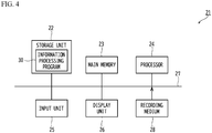
- FIG 4 is a diagram illustrating the hardware structure of an information processing apparatus according to the present embodiment.
- An information processing apparatus 21 is a computer such as a PC or a server that outputs intermediate codes of the program executed by the target processor 1 described above.
- the information processing apparatus 21 includes a storage unit 22, a main memory 23, a processor 24, an input unit 25, and a display unit 26. These elements are connected to each other by a bus 27.
- the storage unit 22 is a secondary storage device such as a hard disk drive (HDD) or an solid state drive (SSD), and stores an information processing program 30 according to the present embodiment.
- the information processing program 30 is a program for reducing the number of instructions in the input instruction sequence as described later.
- the information processing program 30 may be recorded on a non-transitory computer-readable recording medium 28, and the processor 24 may read the information processing program 30 on the recording medium 28.
- Examples of such a recording medium 28 include a physical portable recording media such as a compact disc-read only memory (CD-ROM), a digital versatile disc (DVD), and a universal serial bus (USB) memory.
- a semiconductor memory such as a flash memory or a hard disk drive may be used as the recording medium 28.
- the recording medium 28 is not a transitory medium such as a carrier wave having no physical entity.
- the information processing program 30 may be stored in a device connected to a public line, the Internet, a LAN (Local Area Network), or the like, and the processor 24 may read the information processing program 30 from the device to execute the information processing program 30.
- a public line the Internet
- a LAN Local Area Network
- main memory 23 is hardware that temporarily stores data such as a DRAM, and the information processing program 30 is loaded on the main memory 23.
- the processor 24 is hardware such as a central processing unit (CPU) that controls each unit of the information processing apparatus 21 and executes the information processing program 30 in cooperation with the main memory 23.
- CPU central processing unit
- the processor 24 different from the target processor 11 executes the information processing program 30, but the present embodiment is not limited to this.
- a machine including the target processor 11 may execute the information processing program 30.
- the input unit 25 is an input device such as a keyboard or a mouse. When a user operates the input device, the instruction sequence to be processed by the information processing program 30 is designated, and an output destination of the processed instruction sequence is designated.
- the display unit 26 is a display device such as a liquid crystal display that displays various commands used by the user when the information processing program 30 is executed.
- FIG 5 is a diagram illustrating the functional configuration of the information processing apparatus 21 according to the present embodiment.
- the information processing apparatus 21 includes an acquisition unit 41, a generation unit 42, a deletion unit 43, a selection unit 44, and an output unit 45.
- the processor 24 and the main memory 23 work together to execute the information processing program 30, whereby each of these units is realized.
- the acquisition unit 41 is a functional unit that acquires the instruction sequence.
- the acquisition unit 41 acquires an instruction sequence 50 illustrated in FIG 6 .
- FIG 6 is a diagram illustrating an example of the instruction sequence 50 acquired by the acquisition unit 41.
- the instruction sequence 50 is an intermediate code for generating a binary file to be executed by the target processor 1, and is a sequence in which an instruction A, an instruction B, an instruction C, an instruction D and nop instructions are arranged from the top in an execution order.
- Examples of the instructions A, B, C, and D include an arithmetic operation instruction, a logical operation instruction, a jump instruction, the memory reference instruction, and the like.
- the nop instruction is an instruction for stalling the pipeline by not changing the contents of pipeline registers, the register file, the main memory, and the like, as described above.
- the nop instruction is realized by "sll $0, $0, 0" having an equivalent function to the nop instruction.
- the instruction D depends on the instruction A and reads the register into which the instruction A write some data. It is also assumed that the instruction C depends on the instruction B and reads the register into which the instruction B write some data.
- the nop instructions are inserted into the instruction sequence 50 in order to prevent the data hazard from occurring due to such dependency in the instructions.
- the acquisition unit 41 acquires the instruction sequence 50 including the nop instructions is described as an example.
- the information processing program 30 itself may compile a source code to generate the instruction sequence 50. Since the number of instructions in the instruction sequence 50 is increased by the nop instructions as described above, the number of instructions is reduced in the present embodiment as described later.
- FIGs. 7A to 7C are diagrams illustrating a generation method of generating the candidates of the instruction sequences.
- three candidates P1 to P3 are generated in this example.
- These candidates P1 to P3 are generated by replacing at least a part of the plurality of nop instructions in the original instruction sequence 50 with the wait instruction.
- the wait instruction is the instruction, by one issuance, that waits until all the preceding instructions are completed.
- the candidate P1 is generated by replacing three consecutive nop instructions in the instruction sequence 50 with a single wait instruction.
- the instruction C starts after the instructions A and B complete, the data hazard due to the dependency between the instructions B and C does not occur.
- the data hazard due to the dependency between the instructions A and D does not occur.
- the candidate P2 is generated by replacing two consecutive nop instructions in the instruction sequence 50 with the single wait instruction.
- the instruction D starts after all the preceding instructions complete. Therefore, the data hazard due to the dependency between the instructions A and D does not occur.
- the candidate P3 is generated by replacing three consecutive nop instructions in the instruction sequence 50 with the single wait instruction, and replacing another two consecutive nop instructions in the instruction sequence 50 with another single wait instruction.
- the data hazard does not occur as in the candidates P1 and P2.
- the number of instructions in each of the candidates P1 to P3 can be reduced as compared with the case where only one of the plurality of nop instructions is replaced with the wait instruction. Furthermore, when the candidate in which only one of the nop instructions is replaced with the wait instruction is allowed, the number of candidates increases unnecessarily. However, when the consecutive nop instructions are collectively replaced with the wait instruction as in this example, the increase in the number of candidates can be suppressed.
- the candidates P1 to P3 are obtained by simply replacing the consecutive nop instructions with the wait instruction in the original instruction sequence 50. Thus, there is room for these candidates P1 to P3 to reduce the number of instructions.
- the deletion unit 43 deletes an unnecessary nop instruction and unnecessary wait instruction from each of the candidates P1 to P3.
- FIGs. 8A to 8C are diagrams illustrating a method of deleting the unnecessary nop instruction and the unnecessary wait instruction. Whether the nop instruction or the wait instruction is unnecessary is determined from the viewpoint of whether the execution result of the instruction sequence does not change even when the nop instruction and the wait instruction is deleted.
- the deletion unit 43 deletes the two consecutive nop instructions in the candidate P1.
- the deletion unit 43 does not delete the wait instruction in the candidate P1.
- the deletion unit 43 determines whether the nop instruction and the wait instruction in the candidates P2 and P3 can be deleted. Then, the deletion unit 43 deletes these instructions, when the deletion unit 43 determines that these instructions can be deleted.
- the deletion unit 43 deletes the second wait instruction in the candidate P3.
- the selection unit 44 selects one candidate having the number of instructions equal to or less than a predetermined number No, and having the smallest number of execution cycles among the candidate P1 to P3 which are subjected the deletion as in FIGs. 8A to 8C .
- the predetermined number No is set as the upper limit number.
- the upper limit number may be set in advance to the number of instructions in order to reduce the memory usage, and such an upper limit number may be adopted as the predetermined number N 0 .
- the selection method of the candidate will be described with reference to FIGs. 9A to 9C .
- FIGs. 9A to 9C are diagrams schematically illustrating the number of execution cycles of the instruction sequences in the candidates P1 to P3.
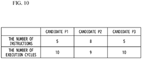
- the selection unit 44 calculates the number of execution cycles of the respective candidates P1 to P3 by using the number of cycles from the issuance of the instructions A, B, C and D to the completion thereof.
- the number of execution cycles of the candidate P1 calculated in this way becomes 10. Also, the number of execution cycles of the candidate P2 becomes 9, and the number of execution cycles of the candidate P3 becomes 10.
- the selection unit 44 calculates the number of instructions included in the respective instruction sequences of the candidates P1 to P3.
- FIG 10 is a diagram illustrating the number of execution cycles and the number of instructions obtained for each of the candidates P1 to P3.
- the candidate P2 thus selected is the instruction sequence having the smallest number of execution cycles among the instruction sequences in which the data hazard does not occur. Therefore, when a binary file obtained by compiling the instruction sequence of the candidate P2 is executed in the target processor 1 (see FIG 3 ), the occurrence of data hazard can be prevented and the execution speed of the program can be improved.
- the output unit 45 (see FIG 5 ) outputs the instruction sequence of the candidate P2 as a final output result.
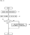
- FIG 11 is a flowchart illustrating the information processing method according to the present embodiment.
- the acquisition unit 41 acquires the instruction sequence 50 of FIG 6 in step S 1.
- step S2 the acquisition unit 41 counts the number N of instructions included in the instruction sequence 50.
- step S3 the acquisition unit 41 determines whether the number N of the instructions is equal to or less than the predetermined number N 0 .
- the acquisition unit 41 determines whether the number N of the instructions is equal to or less than the predetermined number N 0 .
- step S3 when it is determined in step S3 that the number N of instructions is not equal to or less than the predetermined number N 0 (NO), deletion processing of the number of instructions is executed in step S4.
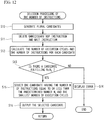
- FIG 12 is a flowchart illustrating the deletion processing of the number of instructions.
- step S10 the generation unit 42 generates the plurality of candidates P1 to P3 (see FIGs. 7A to 7C ) of new instruction sequences having the same execution result as the instruction sequence 50.
- step S11 the deletion unit 43 deletes the unnecessary nop instruction and the unnecessary wait instruction in each of the candidates P1 to P3, as illustrated in FIGs. 8A to 8C .
- step S12 the selection unit 44 calculates the number of execution cycles and the number N of instructions of the instruction sequence for each of the candidates P1 to P3, as illustrated in FIG 10 .
- step S13 the selection unit 44 determines whether there is a candidate in which the number N of instructions is equal to or less than the predetermined number N 0 among the candidates P1 to P3.
- the output unit 45 outputs an error in step S14 and ends the process.
- step S13 when it is determined in step S13 that there is the candidate in which the number N of instructions is equal to or less than the predetermined number N 0 (YES), the process proceeds to step S15.
- step S15 the selection unit 44 selects one candidate having the number N of instructions equal to or less than the predetermined number N 0 , and having the smallest number of execution cycles among the candidates P1 to P3.
- the predetermined number N 0 is 8 as in FIG 10
- the candidate P2 having a smaller number of execution cycles than any other candidates are selected.
- step S16 the output unit 45 outputs the candidate P2 selected in step S15.
- step S10 the generation unit 42 generates the candidates P1 to P3 of new instruction sequences in which the part of the plurality of nop instructions is replaced with the wait instructions. Then, in step S11, the deletion unit 43 deletes the unnecessary nop instruction and the unnecessary wait instruction from the instruction sequence of each of the candidates P1 to P3. In step S15, the selection unit 44 selects the candidate having the number N of instructions equal to or less than the predetermined number N 0 and the smallest number of execution cycles among the candidates P1 to P3 which is subjected to the deletion of the unnecessary nop instruction and the unnecessary wait instruction.
- the instruction sequence selected in this way has the same execution result as the original instruction sequence 50 but has a smaller number of instructions than the original instruction sequence 50. Therefore, the instruction, such as the rep instruction, having the upper limit number with respect to the subsequent instructions can be used. Moreover, even when the rep instruction is not used, the memory usage can be decreased by reducing the number of instructions.
- the selection unit 44 selects the candidate having the smallest number of execution cycles among the plurality of candidates having the number N of instructions equal to or less than the predetermined number N 0 . Therefore, technical improvement in reducing the execution time of the program can be achieved.
- FIG 13A is a diagram illustrating an instruction sequence 60 according to this example.
- the instruction sequence 60 used in the DLU of 8 SIMD Single Instruction Multiple Data
- the instruction sequence 60 is an instruction sequence that forms a basic block inside the loop process.
- the loop process which calculates an average value of respective elements of two vectors is considered.
- the element of each vector is a 32-bit unsigned integer, and the number of elements of each vector is 8 ⁇ 128.
- the meaning of each instruction in the instruction sequence 60 is as follows.
- %xor_xy ixors %x, %y ... Write the logical exclusive OR of the contents of a register "x" and a register "y” to a register "xor_xy".
- %and_xy iands %x, %y ... Write the logical AND of the contents of the register "x" and the register "y” to a register "and_xy".
- %srl_xor_xy isrls %xor_xy, 1 ... Logically shift the contents of the register "xor_xy" to the right by 1 bit, and write the result to a register "srl_xor_xy".
- %res iadds %and_xy, %srl_xor_xy ... Write the arithmetic sum of the contents of the register "and_xy” and the register "srl_xor_xy” to a register "res”.
- the 8 SIMD is considered as described above, and the numbers of all the registers are automatically shifted by 8 every time the instruction sequence 60 is executed.
- the average values of 8 ⁇ 128 elements are written in the register "res" while the number of the register "res" is shifted by 8.
- FIG 13B is a diagram illustrating the dependency of the respective instructions included in the instruction sequence 60.
- arrows are provided between the instructions having the dependency.
- the direction of each arrow indicates an order of appearance of each instruction in the instruction sequence 60.
- the iadds instruction appears in the instruction sequence after the iands instruction appears.
- the isrls instruction starts after 8 clock cycles elapsed since the first ixors instruction started. Thereby, the data hazard due to the dependency of ixors and the isrls can be avoided.
- the iadds instruction starts after 8 clock cycles elapsed since the isrls instruction started. As a result, the data hazard due to the dependency of the isrls and the iadds instructions can be avoided.
- the rep instruction As described above, there is the rep instruction as an instruction for repeatedly executing the instruction sequence 60. However, while the upper limit of the number of subsequent instructions that can be repeatedly executed by the rep instruction is 12, the number of instructions in the instruction sequence 60 is 17. Therefore, in this state, the instruction sequence 60 cannot be repeatedly executed by the rep instruction.
- the information processing method according to the present embodiment illustrated in FIGs. 11 and 12 may be applied to the instruction sequence 60 to reduce the number of instructions.
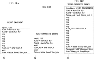
- FIG 14A is a diagram illustrating an instruction sequence 71 in which the number of instructions is reduced by applying the present embodiment to the instruction sequence 60.
- the output unit 45 adds the rep instruction to the instruction sequence 71, and outputs the instruction sequence 71 added with the rep instruction, for example.
- the intermediate code having the loop processing in which the instruction sequence 71 is repeated by the number of times assigned by the second argument of the rep instruction can be obtained.
- the second argument of the rep instruction is 128.
- the first argument of the rep instruction is 11, which indicates the number of instructions in the instruction sequence 71 to be repeated.
- FIG 14B is a diagram illustrating an instruction sequence 72 according to a first comparative example.
- the instruction sequence 72 according to the first comparative example is an instruction sequence obtained by replacing all consecutive nop instructions in the original instruction sequence 60 with the single wait instruction. Since the number of instructions in the instruction sequence 72 is 6, the instruction sequence 72 can be repeatedly executed by the rep instruction. When the rep instruction is used in this way, the first argument of the rep instruction is 6 which is the number of instructions in the instruction sequence 72, and the second argument is 128 which is the number of repeats.
- FIG 14C is a diagram illustrating an instruction sequence 73 according to a second comparative example.
- the instruction sequence 73 according to the second comparative example is an instruction sequence that implements the loop process with the use of a jump instruction without reducing the number of instructions in the original instruction sequence 60.
- a register "loop_cnt” in which the number of loops is written and a register “baseadr” in which a base address common to all the registers is written are used in order to realize the loop processing. Further, a register "inc” in which an increment value of the base address is written is also used. Since the 8 SIMD is considered in this example as described above, the increment value is 8.
- %loop_cnt sub %loop_cnt, 1 ... Decrease the number of loops written in the register "loop_cnt" by 1.
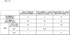
- FIG 15 is a diagram illustrating the number of instructions included in each of the instruction sequence 71 according to the present embodiment, the instruction sequence 72 according to the first comparative example, and the instruction sequence 73 according to the second comparative example.
- FIG 15 also illustrates the number of execution cycles when each of these instruction sequences executed once.
- both of the number of instructions and the number of execution cycles becomes larger than those in the present embodiment.
- the output unit 45 may output the instruction sequence 73 that realizes the loop process with the use of the jump instruction as illustrated in FIG. 14C instead of displaying an error as in step S14 of FIG. 12 .
- the instruction sequence 73 is an instruction sequence in which a sub instruction, an add instruction, and a bnzr instruction are added to the original instruction sequence 60 ( FIG 13A ) as described above, and the instruction sequence 73 can obtain the same execution result as the case ( FIG. 14A ) where the rep instruction is used.
Landscapes
- Engineering & Computer Science (AREA)
- Theoretical Computer Science (AREA)
- Software Systems (AREA)
- General Engineering & Computer Science (AREA)
- Physics & Mathematics (AREA)
- General Physics & Mathematics (AREA)
- Executing Machine-Instructions (AREA)
- Advance Control (AREA)
Abstract
Description
- The present invention relates to an information processing apparatus, a program and an information processing method.
- There is a pipeline system as a system for increasing the throughput of instructions in a processor. In the pipeline system, an execution stage of the instruction is divided into respective stages such as instruction fetch, instruction decode, instruction execution, memory reference, and write back to a register. Then, a plurality of instructions are sequentially input to respective stages, so that the plurality of instructions are executed in parallel in the processor, and the execution time of a program is reduced.
- In the pipeline system, various hazards that lead a cause for not obtaining a correct execution result may occur. One of the hazards is a data hazard. The data hazard is a hazard in which even though a preceding instruction does not written a result to a register yet, a subsequent instruction that uses the result of the preceding instruction reads the register.
- One of the methods for avoiding the data hazard is called a forwarding. The forwarding is a technique for supplying a result of the previous instruction to the subsequent instruction before the previous instruction writes the result to the register. Although the data hazard is eliminated in this technique, there is a need for providing a wiring in the processor to perform the forwarding, which in turn complicates the hardware structure of the processor.
- There is also a method of avoiding the data hazard by stalling the pipeline without performing the forwarding. The stall is a technique in which a nop (no operation) instruction is inserted between the preceding instruction and the succeeding instruction, so that the succeeding instruction is not input into the pipeline until the preceding instruction writes the result in a register. Note that the technique related to the present disclosure is also disclosed in Japanese Laid-open Patent Publications Nos.
11-073327 2001-350632 - However, in the method of avoiding the data hazard by the stall, there is room for improving the execution time of the program.
- It is desirable to reduce the execution time of a program.
- According to an aspect of the present disclosure, there is provided an information processing apparatus including: an acquisition unit configured to acquire an instruction sequence including a plurality of instructions; a generation unit configured to generate a plurality of candidates of new instruction sequences capable of obtaining an execution result as same as in the instruction sequence, by replacing at least a part of a plurality of nop instructions included in the instruction sequence with a wait instruction that waits for completion of all preceding instructions; a deletion unit configured to delete any one of the nop instructions and the wait instruction from each of the new instruction sequences, when the execution result does not change in case any one of the nop instructions and the wait instruction is deleted from the new instruction sequences in the candidates; and a selection unit configured to select a one candidate among the plurality of candidates subjected to the delete, the one candidate having the number of instructions equal to or less than a certain number, and having a smallest number of execution cycles among the plurality of candidates.
- According to an embodiment, it is possible to reduce the execution time of a program.
-
-
FIGs. 1A and 1B are diagrams schematically illustrating the number of execution cycles of instruction sequences; -
FIG 2 is a table illustrating the number of instructions and the number of execution cycles in each of the instruction sequences inFIGs. 1A and 1B ; -
FIG 3 is a diagram illustrating the hardware structure of a target processor according to a present embodiment; -
FIG 4 is a diagram illustrating the hardware structure of an information processing apparatus according to the present embodiment; -
FIG 5 is a diagram illustrating the functional configuration of the information processing apparatus according to the present embodiment; -
FIG 6 is a diagram illustrating an example of an instruction sequence acquired by an acquisition unit according to the present embodiment; -
FIGs. 7A to 7C are diagrams illustrating a generation method in which a generation unit according to the present embodiment generates candidates of the instruction sequences; -
FIGs. 8A to 8C are diagrams illustrating a method in which a deletion unit according to the present embodiment deletes a nop instruction and a wait instruction from the instruction sequences of the candidates; -
FIGs. 9A to 9C are diagrams schematically illustrating the number of execution cycles of the instruction sequences in the candidates according to the present embodiment; -
FIG 10 is a diagram illustrating the number of execution cycles and the number of instructions obtained for each candidate in the present embodiment; -
FIG 11 is a flowchart illustrating an information processing method according to the present embodiment (part 1); -
FIG 12 is a flowchart illustrating an information processing method according to the present embodiment (part 2); -
FIG 13A is a diagram illustrating an example of the instruction sequence according to the present embodiment; -
FIG 13B is a diagram illustrating dependency of respective instructions included in the instruction sequence; -
FIG 14A is a diagram illustrating an instruction sequence in which the number of instructions is reduced by applying the present embodiment to the instruction sequence ofFIG 13A ; -
FIG 14B is a diagram illustrating an instruction sequence according to a first comparative example; -
FIG 14C is a diagram illustrating an instruction sequence according to a second comparative example; and -
FIG 15 is a diagram illustrating the number of instructions included in each of the instruction sequences according to the present embodiment, the first comparative example and the second comparative example, and the number of execution cycles when each of the instruction sequences has been executed once. - Prior to the description of the present embodiment, matters studied by an inventor will be described.
- A pipeline may be stalled in order to avoid the data hazard without employing the forwarding which leads to complicated hardware structure. The stall is a technique for temporarily stopping the pipeline, and can be realized by inserting an no operation instruction (hereinafter referred to as "a nop instruction") between a preceding instruction and a succeeding instruction. The nop instruction is an instruction that does not change the contents of pipeline registers, a register file, a main memory, and the like. In a stage where the nop instruction exists, the contents of each of the registers and the main memory described above do not change, and the stall which stops the pipeline can therefore be executed.
- However, the nop instruction completes in one clock cycle after the nop instruction is issued. Therefore, the number of nop instructions is required to become as many as the number of clock cycles to be stalled, and hence the number of instructions in the entire program increases.
- Particularly, some instruction set includes such an instruction that provide an upper limit number for the number of the subsequent instructions. In this instruction set, the number of the subsequent instructions may exceed the upper limit number by the nop instruction. Examples of such instructions having the upper limit number include a rep instruction in the DLU architecture, and a loop instruction and a loopcc instruction in the X86 architecture.
- Among these instructions, the rep instruction is an instruction that instructs repeat of the subsequent instruction, and is described in a format of "rep n, m". A first argument "n" is an integer value representing the number of instructions to be repeated. A second argument "m" is an integer value representing the number of repeats. In the DLU, an upper limit value of the first argument "n" is 12. Therefore, the rep instruction cannot repeatedly execute the subsequent instructions more than 12 instructions.
- In order to reduce the number of nop instructions in the instruction sequence, the nop instructions may be replaced with a wait instruction. The wait instruction is an instruction that waits until all the preceding instructions are completed, and can stall the pipeline as in the nop instruction. Moreover, the wait instruction can stall the pipeline by one issuance. Therefore, the number of instructions can be reduced compared with the case of using the nop instruction.
- However, according to a result of studies conducted by the inventor of the present application, it was clarified that the number of execution cycles in the entire instruction sequence increases rather than decreases when the nop instructions is simply replaced with the wait instruction. This will be described with reference to
FIGs. 1A and 1B . -
FIGs. 1A and 1B are diagrams schematically illustrating the number of execution cycles of instruction sequences. -
FIG 1A illustrates aninstruction sequence 1 that stalls the pipeline by the nop instructions. - The
instruction sequence 1 has three instructions A, B, and C, and is executed in order from the top to the bottom as a clock cycle advances. - It is assumed that each of the instructions A and B requires 4 clock cycles from the issuance of each instruction to the completion. It is also assumed that the instruction C depends on the instruction A, and the instruction C reads the register into which the instruction A wrote some data. Therefore, when the pipeline is not stalled between the instructions A and C, the data hazard occurs. This is also the case for an
instruction sequence 2 inFIG 1B . - In order to stall the pipeline, two nop instructions are continuously inserted between the instructions B and C in the
instruction sequence 1. Here, it is assumed that the nop instruction is completed in one clock cycle. - Thereby, the instruction C starts after the instruction A is completed, and the data hazard can therefore be avoided. However, since the two nop instructions are inserted, the number of instructions included in the
instruction sequence 1 becomes long as many as five. - On the other hand,
FIG 1B illustrates theinstruction sequence 2 that stalls the pipeline by the wait instruction. - The wait instruction is an instruction that waits for the start of the subsequent instruction until all the preceding instructions are completed. By issuing the wait instruction only once, the function of the wait instruction can be realized. In this example, the preceding instructions for the wait instruction are the instructions A and B. Therefore, the instruction C starts after both of the instructions A and B are completed, so that the data hazard can be avoided.
- In this way, since the wait instruction can stall the pipeline only by one issue, the number of instructions in the
instruction sequence 2 can be reduced compared with the number of instructions in theinstruction sequence 1 using the nop instructions (FIG 1A ). - However, when the wait instruction is used, 6 clock cycles are required from the start of the instruction A to the completion of the instruction C, and hence the number of execution cycles in the entire program is increased compared with the
instruction sequence 1 using the nop instructions (FIG 1A ). -
FIG 2 is a table illustrating the number of instructions and the number of execution cycles in each of theinstruction sequences FIGs. 1A and 1B . - As illustrated in
FIG 2 , theinstruction sequence 1 that stalls the pipeline only with the nop instruction has a larger number of instructions than theinstruction sequence 2 that stalls the pipeline with the wait instruction. Therefore, in a program having a larger number of instructions than this example, the number of instructions may exceed the upper limit of the number of subsequent instructions that can be executed repeatedly by the rep instruction, and there is a possibility that the loop processing cannot be executed using the rep instruction. - Moreover, even when the rep instruction is not used, the memory usage increases due to an increase in the total number of instructions. Therefore, there is a possibility that an application program for a device having a small memory size such as an embedded device cannot be stored in the memory.
- On the other hand, in the
instruction sequence 2 that stalls the pipeline with the wait instruction, the number of instructions can be reduced compared with theinstruction sequence 1. - However, the number of execution cycles increases conversely, and the execution time of the program becomes long.
- Hereinafter, a description will be given of a present embodiment that can reduce the number of instructions and suppress an increase in the execution time of the program.
-
FIG 3 is a diagram illustrating the hardware structure of a target processor according to the present embodiment. - A
target processor 11 is a processor that can execute pipeline processing to the instruction set of the above-mentioned DLU architecture, for example. Also, thetarget processor 11 is a processor that processes the instruction sequence by in-order execution, and the instructions are executed in order from the top of the instruction sequence. - In this example, the
target processor 11 includes an instruction fetchunit 12, aninstruction decode unit 13, anexecution unit 14, and a write-back unit 15. These units are registers and arithmetic circuits formed on a semiconductor substrate, and correspond to stages of IF (Instruction Fetch), ID (Instruction Decode), EX (Execution), and WB (Write Back) in the pipeline processing, respectively. - The IF stage is a stage in which the instruction fetch
unit 12 sequentially fetches instructions included in the instruction sequence. The ID stage is a stage in which theinstruction decode unit 13 receives the instructions from the instruction fetchunit 12 and decodes the received instructions. - The EX stage is a stage in which the
execution unit 14 executes arithmetic operation or logical operation in accordance with the instructions decoded by theinstruction decode unit 13. Here, data to be used in these operations is written in an unillustrated register in advance. - The WB stage is a stage in which the write-
back unit 15 writes back an operation result output from theexecution unit 14 in the EX stage to the register file. - In the
target processor 11, aforwarding line 16 for avoiding the data hazard does not exist. The forwardingline 16 is a wiring that supplies, to the EX stage, data before input to the WB stage. By omitting the wiring in this manner, the hardware structure of thetarget processor 11 can be prevented from being complicated. - In addition to the aforementioned DLU, other processor like MIPS R2000, MIPS R3000, and C6000 VLIW family manufactured by Texas Instruments are examples of the processors that does not have the
forwarding line 16, and these processors may be used as thetarget processor 11. - Note that a memory reference instruction such as a store instruction is not used in order to simplify the explanation in the followings. However, when the memory reference instruction is used, a MEM stage for executing memory reference may be provided between the EX stage and the WR stage.
-
FIG 4 is a diagram illustrating the hardware structure of an information processing apparatus according to the present embodiment. - An
information processing apparatus 21 is a computer such as a PC or a server that outputs intermediate codes of the program executed by thetarget processor 1 described above. - In this example, the
information processing apparatus 21 includes astorage unit 22, amain memory 23, aprocessor 24, aninput unit 25, and adisplay unit 26. These elements are connected to each other by abus 27. - The
storage unit 22 is a secondary storage device such as a hard disk drive (HDD) or an solid state drive (SSD), and stores aninformation processing program 30 according to the present embodiment. Theinformation processing program 30 is a program for reducing the number of instructions in the input instruction sequence as described later. - Here, the
information processing program 30 may be recorded on a non-transitory computer-readable recording medium 28, and theprocessor 24 may read theinformation processing program 30 on therecording medium 28. - Examples of such a
recording medium 28 include a physical portable recording media such as a compact disc-read only memory (CD-ROM), a digital versatile disc (DVD), and a universal serial bus (USB) memory. A semiconductor memory such as a flash memory or a hard disk drive may be used as therecording medium 28. Therecording medium 28 is not a transitory medium such as a carrier wave having no physical entity. - Moreover, the
information processing program 30 may be stored in a device connected to a public line, the Internet, a LAN (Local Area Network), or the like, and theprocessor 24 may read theinformation processing program 30 from the device to execute theinformation processing program 30. - On the other hand, the
main memory 23 is hardware that temporarily stores data such as a DRAM, and theinformation processing program 30 is loaded on themain memory 23. - The
processor 24 is hardware such as a central processing unit (CPU) that controls each unit of theinformation processing apparatus 21 and executes theinformation processing program 30 in cooperation with themain memory 23. - In the present embodiment, it is assumed that the
processor 24 different from the target processor 11 (seeFIG 3 ) executes theinformation processing program 30, but the present embodiment is not limited to this. For example, a machine including thetarget processor 11 may execute theinformation processing program 30. - The
input unit 25 is an input device such as a keyboard or a mouse. When a user operates the input device, the instruction sequence to be processed by theinformation processing program 30 is designated, and an output destination of the processed instruction sequence is designated. - The
display unit 26 is a display device such as a liquid crystal display that displays various commands used by the user when theinformation processing program 30 is executed. -
FIG 5 is a diagram illustrating the functional configuration of theinformation processing apparatus 21 according to the present embodiment. - As illustrated in
FIG 5 , theinformation processing apparatus 21 includes anacquisition unit 41, ageneration unit 42, adeletion unit 43, aselection unit 44, and anoutput unit 45. Theprocessor 24 and themain memory 23 work together to execute theinformation processing program 30, whereby each of these units is realized. - The
acquisition unit 41 is a functional unit that acquires the instruction sequence. For example, theacquisition unit 41 acquires aninstruction sequence 50 illustrated inFIG 6 . -
FIG 6 is a diagram illustrating an example of theinstruction sequence 50 acquired by theacquisition unit 41. - The
instruction sequence 50 is an intermediate code for generating a binary file to be executed by thetarget processor 1, and is a sequence in which an instruction A, an instruction B, an instruction C, an instruction D and nop instructions are arranged from the top in an execution order. Examples of the instructions A, B, C, and D include an arithmetic operation instruction, a logical operation instruction, a jump instruction, the memory reference instruction, and the like. - The nop instruction is an instruction for stalling the pipeline by not changing the contents of pipeline registers, the register file, the main memory, and the like, as described above. In MIPS, the nop instruction is realized by "sll $0, $0, 0" having an equivalent function to the nop instruction.
- It is assumed that all these instructions are issued in one clock cycle. The number of cycles needed to complete the instruction from its issuance are as follows;
- instruction A: 8 clock cycles,
- instruction B: 4 clock cycles,
- instruction C: 1 clock cycle,
- instruction D: 1 clock cycle, and
- nop instruction: 1 clock cycle.
- Further, it is assumed that the instruction D depends on the instruction A and reads the register into which the instruction A write some data. It is also assumed that the instruction C depends on the instruction B and reads the register into which the instruction B write some data.
- The nop instructions are inserted into the
instruction sequence 50 in order to prevent the data hazard from occurring due to such dependency in the instructions. Hereinafter, the case where theacquisition unit 41 acquires theinstruction sequence 50 including the nop instructions is described as an example. However, theinformation processing program 30 itself may compile a source code to generate theinstruction sequence 50. Since the number of instructions in theinstruction sequence 50 is increased by the nop instructions as described above, the number of instructions is reduced in the present embodiment as described later. - Referring to
FIG 5 again, thegeneration unit 42 generates a plurality of candidates of new instruction sequences having the same execution result as the above-mentionedinstruction sequence 50.FIGs. 7A to 7C are diagrams illustrating a generation method of generating the candidates of the instruction sequences. - As illustrated in
FIGs. 7A to 7C , three candidates P1 to P3 are generated in this example. - These candidates P1 to P3 are generated by replacing at least a part of the plurality of nop instructions in the
original instruction sequence 50 with the wait instruction. As described above, the wait instruction is the instruction, by one issuance, that waits until all the preceding instructions are completed. - For example, the candidate P1 is generated by replacing three consecutive nop instructions in the
instruction sequence 50 with a single wait instruction. In this case, since the instruction C starts after the instructions A and B complete, the data hazard due to the dependency between the instructions B and C does not occur. Similarly, the data hazard due to the dependency between the instructions A and D does not occur. - Also, the candidate P2 is generated by replacing two consecutive nop instructions in the
instruction sequence 50 with the single wait instruction. In this case, the instruction D starts after all the preceding instructions complete. Therefore, the data hazard due to the dependency between the instructions A and D does not occur. - On the other hand, the candidate P3 is generated by replacing three consecutive nop instructions in the
instruction sequence 50 with the single wait instruction, and replacing another two consecutive nop instructions in theinstruction sequence 50 with another single wait instruction. In this case, the data hazard does not occur as in the candidates P1 and P2. - Note that in any of the candidates P1 to P3, when the plurality of nop instructions appear continuously, the plurality of consecutive nop instructions are replaced with the single wait instruction.
- Therefore, the number of instructions in each of the candidates P1 to P3 can be reduced as compared with the case where only one of the plurality of nop instructions is replaced with the wait instruction. Furthermore, when the candidate in which only one of the nop instructions is replaced with the wait instruction is allowed, the number of candidates increases unnecessarily. However, when the consecutive nop instructions are collectively replaced with the wait instruction as in this example, the increase in the number of candidates can be suppressed.
- Note that the candidates P1 to P3 are obtained by simply replacing the consecutive nop instructions with the wait instruction in the
original instruction sequence 50. Thus, there is room for these candidates P1 to P3 to reduce the number of instructions. - Therefore, the deletion unit 43 (see
FIG 5 ) deletes an unnecessary nop instruction and unnecessary wait instruction from each of the candidates P1 to P3. -
FIGs. 8A to 8C are diagrams illustrating a method of deleting the unnecessary nop instruction and the unnecessary wait instruction. Whether the nop instruction or the wait instruction is unnecessary is determined from the viewpoint of whether the execution result of the instruction sequence does not change even when the nop instruction and the wait instruction is deleted. - For example, even when the two consecutive nop instructions of the candidate P1 are deleted, since the instruction A completes before the instruction D starts, the data hazard due to the dependency between the instructions A and D does not occur, and hence the execution result does not change before and after the deletion. Therefore, the
deletion unit 43 deletes the two consecutive nop instructions in the candidate P1. - On the other hand, when the wait instruction of the candidate P1 is deleted, the instruction C starts before the instruction B completes. Since the instructions B and C have the dependency as described above, when the wait instruction is deleted in this way, an instruction sequence having a different execution result than that of the original instruction sequence is unsuccessfully obtained. Therefore, the
deletion unit 43 does not delete the wait instruction in the candidate P1. - In the same manner as the candidate P1, the
deletion unit 43 determines whether the nop instruction and the wait instruction in the candidates P2 and P3 can be deleted. Then, thedeletion unit 43 deletes these instructions, when thedeletion unit 43 determines that these instructions can be deleted. - For example, the execution result of the candidate P2 changes before and after deleting the nop instruction or the wait instruction, and hence these instructions are not deleted from the candidate P2. In contrast, since the execution result of the candidate P3 does not change even when the second wait instruction is deleted, the
deletion unit 43 deletes the second wait instruction in the candidate P3. - The selection unit 44 (see
FIG 5 ) selects one candidate having the number of instructions equal to or less than a predetermined number No, and having the smallest number of execution cycles among the candidate P1 to P3 which are subjected the deletion as inFIGs. 8A to 8C . - When an instruction, such as rep instruction, having an upper limit number with respect to the number of subsequent instructions is used, the predetermined number No is set as the upper limit number. Even when the rep instruction is not used, the upper limit number may be set in advance to the number of instructions in order to reduce the memory usage, and such an upper limit number may be adopted as the predetermined number N0. The selection method of the candidate will be described with reference to
FIGs. 9A to 9C . -
FIGs. 9A to 9C are diagrams schematically illustrating the number of execution cycles of the instruction sequences in the candidates P1 to P3. - The
selection unit 44 calculates the number of execution cycles of the respective candidates P1 to P3 by using the number of cycles from the issuance of the instructions A, B, C and D to the completion thereof. The number of execution cycles of the candidate P1 calculated in this way becomes 10. Also, the number of execution cycles of the candidate P2 becomes 9, and the number of execution cycles of the candidate P3 becomes 10. - Further, the
selection unit 44 calculates the number of instructions included in the respective instruction sequences of the candidates P1 to P3. -
FIG 10 is a diagram illustrating the number of execution cycles and the number of instructions obtained for each of the candidates P1 to P3. - In this example, it is assumed that the predetermined number No of the number of instructions is 8. In this case, the
selection unit 44 selects the candidate P2, which has the smallest number of execution cycles among the candidates P1 to P3 that have the number of instructions equal to or less than the predetermined number N0 (= 8). - The candidate P2 thus selected is the instruction sequence having the smallest number of execution cycles among the instruction sequences in which the data hazard does not occur. Therefore, when a binary file obtained by compiling the instruction sequence of the candidate P2 is executed in the target processor 1 (see
FIG 3 ), the occurrence of data hazard can be prevented and the execution speed of the program can be improved. - Then, the output unit 45 (see
FIG 5 ) outputs the instruction sequence of the candidate P2 as a final output result. - Next, a description will be given of an information processing method according to the present embodiment.
FIG 11 is a flowchart illustrating the information processing method according to the present embodiment. - First, the
acquisition unit 41 acquires theinstruction sequence 50 ofFIG 6 instep S 1. - Next, the process proceeds to step S2, where the
acquisition unit 41 counts the number N of instructions included in theinstruction sequence 50. - Then, in step S3, the
acquisition unit 41 determines whether the number N of the instructions is equal to or less than the predetermined number N0. Here, when it is determined that the number N of the instructions is equal to or less than the predetermined number N0 (YES), there is no need to reduce the instruction in theinstruction sequence 50. Therefore, the process ends successfully in this case. - On the other hand, when it is determined in step S3 that the number N of instructions is not equal to or less than the predetermined number N0 (NO), deletion processing of the number of instructions is executed in step S4.
-
FIG 12 is a flowchart illustrating the deletion processing of the number of instructions. - First, in step S10, the
generation unit 42 generates the plurality of candidates P1 to P3 (seeFIGs. 7A to 7C ) of new instruction sequences having the same execution result as theinstruction sequence 50. - Next, in step S11, the
deletion unit 43 deletes the unnecessary nop instruction and the unnecessary wait instruction in each of the candidates P1 to P3, as illustrated inFIGs. 8A to 8C . - Then, in step S12, the
selection unit 44 calculates the number of execution cycles and the number N of instructions of the instruction sequence for each of the candidates P1 to P3, as illustrated inFIG 10 . - Subsequently, in step S13, the
selection unit 44 determines whether there is a candidate in which the number N of instructions is equal to or less than the predetermined number N0 among the candidates P1 to P3. When it is determined that there is no candidate in which the number N of instructions is equal to or less than the predetermined number N0 (NO), theoutput unit 45 outputs an error in step S14 and ends the process. - On the other hand, when it is determined in step S13 that there is the candidate in which the number N of instructions is equal to or less than the predetermined number N0 (YES), the process proceeds to step S15.
- In step S15, the
selection unit 44 selects one candidate having the number N of instructions equal to or less than the predetermined number N0, and having the smallest number of execution cycles among the candidates P1 to P3. In the example in which the predetermined number N0 is 8 as inFIG 10 , the candidate P2 having a smaller number of execution cycles than any other candidates are selected. - After that, the process proceeds to step S16, where the
output unit 45 outputs the candidate P2 selected in step S15. - Thus, the basic steps of the information processing method according to the present embodiment are completed.
- According to the present embodiment, in step S10, the
generation unit 42 generates the candidates P1 to P3 of new instruction sequences in which the part of the plurality of nop instructions is replaced with the wait instructions. Then, in step S11, thedeletion unit 43 deletes the unnecessary nop instruction and the unnecessary wait instruction from the instruction sequence of each of the candidates P1 to P3. In step S15, theselection unit 44 selects the candidate having the number N of instructions equal to or less than the predetermined number N0 and the smallest number of execution cycles among the candidates P1 to P3 which is subjected to the deletion of the unnecessary nop instruction and the unnecessary wait instruction. - The instruction sequence selected in this way has the same execution result as the
original instruction sequence 50 but has a smaller number of instructions than theoriginal instruction sequence 50. Therefore, the instruction, such as the rep instruction, having the upper limit number with respect to the subsequent instructions can be used. Moreover, even when the rep instruction is not used, the memory usage can be decreased by reducing the number of instructions. - In addition, the
selection unit 44 selects the candidate having the smallest number of execution cycles among the plurality of candidates having the number N of instructions equal to or less than the predetermined number N0. Therefore, technical improvement in reducing the execution time of the program can be achieved. - Next, a description will be given of a more specific example of the present embodiment.
FIG 13A is a diagram illustrating aninstruction sequence 60 according to this example. In this example, theinstruction sequence 60 used in the DLU of 8 SIMD (Single Instruction Multiple Data) will be described. - The
instruction sequence 60 is an instruction sequence that forms a basic block inside the loop process. Here, the loop process which calculates an average value of respective elements of two vectors is considered. Note that the element of each vector is a 32-bit unsigned integer, and the number of elements of each vector is 8 × 128. The meaning of each instruction in theinstruction sequence 60 is as follows. - %xor_xy = ixors %x, %y ... Write the logical exclusive OR of the contents of a register "x" and a register "y" to a register "xor_xy".
- %and_xy = iands %x, %y ... Write the logical AND of the contents of the register "x" and the register "y" to a register "and_xy".
- %srl_xor_xy = isrls %xor_xy, 1 ... Logically shift the contents of the register "xor_xy" to the right by 1 bit, and write the result to a register "srl_xor_xy".
- %res = iadds %and_xy, %srl_xor_xy ... Write the arithmetic sum of the contents of the register "and_xy" and the register "srl_xor_xy" to a register "res".
- In this example, the 8 SIMD is considered as described above, and the numbers of all the registers are automatically shifted by 8 every time the
instruction sequence 60 is executed. By repeatedly executing theinstruction sequence 60 by 128 times, the average values of 8 × 128 elements are written in the register "res" while the number of the register "res" is shifted by 8. -
FIG 13B is a diagram illustrating the dependency of the respective instructions included in theinstruction sequence 60. - In this example, arrows are provided between the instructions having the dependency. The direction of each arrow indicates an order of appearance of each instruction in the
instruction sequence 60. For example, the iadds instruction appears in the instruction sequence after the iands instruction appears. - All the instructions appearing in
FIG. 13A are completed in 8 clock cycles except for the nop instructions. - Therefore, when six nop instructions are inserted between the iands instruction and the isrls instruction as illustrated in
FIG. 13A , the isrls instruction starts after 8 clock cycles elapsed since the first ixors instruction started. Thereby, the data hazard due to the dependency of ixors and the isrls can be avoided. - Similarly, since seven nop instructions are inserted between the isrls instruction and the iadds instruction, the iadds instruction starts after 8 clock cycles elapsed since the isrls instruction started. As a result, the data hazard due to the dependency of the isrls and the iadds instructions can be avoided.
- As described above, there is the rep instruction as an instruction for repeatedly executing the
instruction sequence 60. However, while the upper limit of the number of subsequent instructions that can be repeatedly executed by the rep instruction is 12, the number of instructions in theinstruction sequence 60 is 17. Therefore, in this state, theinstruction sequence 60 cannot be repeatedly executed by the rep instruction. - In such a case, the information processing method according to the present embodiment illustrated in
FIGs. 11 and12 may be applied to theinstruction sequence 60 to reduce the number of instructions. -
FIG 14A is a diagram illustrating aninstruction sequence 71 in which the number of instructions is reduced by applying the present embodiment to theinstruction sequence 60. - The number of instructions in the
instruction sequence 71 is 11, which is less than the upper limit (= 12) of the number of subsequent instructions that can be executed by the rep instruction. Therefore, theinstruction sequence 71 can be repeatedly executed by the rep instruction. In this case, theoutput unit 45 adds the rep instruction to theinstruction sequence 71, and outputs theinstruction sequence 71 added with the rep instruction, for example. Thus, the intermediate code having the loop processing in which theinstruction sequence 71 is repeated by the number of times assigned by the second argument of the rep instruction can be obtained. In this example, since the number of repeats is 128 as described above, the second argument of the rep instruction is 128. Further, the first argument of the rep instruction is 11, which indicates the number of instructions in theinstruction sequence 71 to be repeated. -
FIG 14B is a diagram illustrating aninstruction sequence 72 according to a first comparative example. - The
instruction sequence 72 according to the first comparative example is an instruction sequence obtained by replacing all consecutive nop instructions in theoriginal instruction sequence 60 with the single wait instruction. Since the number of instructions in theinstruction sequence 72 is 6, theinstruction sequence 72 can be repeatedly executed by the rep instruction. When the rep instruction is used in this way, the first argument of the rep instruction is 6 which is the number of instructions in theinstruction sequence 72, and the second argument is 128 which is the number of repeats. -
FIG 14C is a diagram illustrating aninstruction sequence 73 according to a second comparative example. - The
instruction sequence 73 according to the second comparative example is an instruction sequence that implements the loop process with the use of a jump instruction without reducing the number of instructions in theoriginal instruction sequence 60. - In the second comparative example, a register "loop_cnt" in which the number of loops is written and a register "baseadr" in which a base address common to all the registers is written are used in order to realize the loop processing. Further, a register "inc" in which an increment value of the base address is written is also used. Since the 8 SIMD is considered in this example as described above, the increment value is 8.
- The meaning of each instruction using these registers is as follows.
- %loop_cnt = sub %loop_cnt, 1 ... Decrease the number of loops written in the register "loop_cnt" by 1.
- %baseadr=add %baseadr,%inc ... Increase the base address written in the register "baseadr" by the increment value (= 8) written in the register "inc".
- bnzr %loop_cnt, LoopBegin ... Jump to a label "LoopBegin" when the number of loops written in the register "loop_cnt" is not 0, and execute the subsequent instructions when the number of loops is 0.
-
FIG 15 is a diagram illustrating the number of instructions included in each of theinstruction sequence 71 according to the present embodiment, theinstruction sequence 72 according to the first comparative example, and theinstruction sequence 73 according to the second comparative example.FIG 15 also illustrates the number of execution cycles when each of these instruction sequences executed once. - As illustrated in
FIG. 15 , the number of instructions in the present embodiment is less than the upper limit value (=12) of the number of subsequent instructions that can be executed by the rep instruction. Also, in the first comparative example, the number of instructions is less than the upper limit value. However, the number of execution cycles in the first comparative example is 22, which is larger than the number of execution cycles in the present embodiment. - Furthermore, in the second comparative example, both of the number of instructions and the number of execution cycles becomes larger than those in the present embodiment.
- This result revealed that the present embodiment is effective in reducing the number of instructions and the number of execution cycles.
- In the example of
FIG. 14A , the number of instructions is less than the predetermined number N0 (= 12) assigned to the rep instruction. However, depending on the original instruction sequence, there may be a case where a candidate having the number of instructions equal to or less than the predetermined number N0 does not exist even when the present embodiment is applied. In this case, the output unit 45 (seeFIG. 5 ) may output theinstruction sequence 73 that realizes the loop process with the use of the jump instruction as illustrated inFIG. 14C instead of displaying an error as in step S14 ofFIG. 12 . Theinstruction sequence 73 is an instruction sequence in which a sub instruction, an add instruction, and a bnzr instruction are added to the original instruction sequence 60 (FIG 13A ) as described above, and theinstruction sequence 73 can obtain the same execution result as the case (FIG. 14A ) where the rep instruction is used. - Although the embodiment of the present invention is described in detail, the present invention is not limited to the specifically described embodiments and variations but other embodiments and variations may be made without departing from the scope of the claimed invention.
Claims (7)
- An information processing apparatus (21) comprising:an acquisition unit (41) configured to acquire an instruction sequence including a plurality of instructions;a generation unit (42) configured to generate a plurality of candidates of new instruction sequences capable of obtaining an execution result as same as in the instruction sequence, by replacing at least a part of a plurality of nop instructions included in the instruction sequence with a wait instruction that waits for completion of all preceding instructions;a deletion unit (43) configured to delete any one of the nop instructions and the wait instruction from each of the new instruction sequences, when the execution result does not change in case any one of the nop instructions and the wait instruction is deleted from the new instruction sequences in the candidates; anda selection unit (44) configured to select a one candidate among the plurality of candidates subjected to the delete, the one candidate having the number of instructions equal to or less than a certain number, and having a smallest number of execution cycles among the plurality of candidates.
- The information processing apparatus as claimed in claim 1, wherein
the generation unit (42) is configured to replace consecutive nop instructions with a single wait instruction when the nop instructions continuously appear in the instruction sequence. - The information processing apparatus as claimed in claim 1 or 2, wherein
the certain number is an upper limit number of subsequent instructions allowed by a repeat instruction that instructs repeat of the subsequent instructions. - The information processing apparatus as claimed in claim 3, further comprising:
an output unit (45) configured to add the repeat instruction to the instruction sequence of the selected candidate, where the repeat instruction being instructing a repeat of the instruction sequence, and the output unit (45) is configured to output the instruction sequence added with the repeat instruction. - The information processing apparatus as claimed in claim 3, further comprising:
an output unit (45) configured to output the instruction sequence added with an instruction capable of obtaining an execution result as same as the repeat instruction, when the candidate having the number of instructions equal to or less than the certain number does not exists. - A program that causes a computer to execute a process, the process comprising:acquiring an instruction sequence including a plurality of instructions;generating a plurality of candidates of new instruction sequences capable of obtaining an execution result as same as in the instruction sequence, by replacing at least a part of a plurality of nop instructions included in the instruction sequence with a wait instruction that waits for completion of all preceding instructions;deleting any one of the nop instructions and the wait instruction from each of the new instruction sequences, when the execution result does not change in case any one of the nop instructions and the wait instruction is deleted from the new instruction sequences in the candidates; andselecting a one candidate among the plurality of candidates subjected to the delete, the one candidate having the number of instructions equal to or less than a certain number, and including a smallest number of execution cycles among the plurality of candidates.
- An information processing method causing a computer to execute a process, the process comprising:acquiring an instruction sequence including a plurality of instructions;generating a plurality of candidates of new instruction sequences capable of obtaining an execution result as same as in the instruction sequence, by replacing at least a part of a plurality of nop instructions included in the instruction sequence with a wait instruction that waits for completion of all preceding instructions;deleting any one of the nop instructions and the wait instruction from each of the new instruction sequences, when the execution result does not change in case any one of the nop instructions and the wait instruction is deleted from the new instruction sequences in the candidates; andselecting a one candidate among the plurality of candidates subjected to the delete, the one candidate having the number of instructions equal to or less than a certain number, and having a smallest number of execution cycles among the plurality of candidates.
Applications Claiming Priority (1)
| Application Number | Priority Date | Filing Date | Title |
|---|---|---|---|
| JP2019016819A JP7208448B2 (en) | 2019-02-01 | 2019-02-01 | Information processing device, information processing program, and information processing method |
Publications (2)
| Publication Number | Publication Date |
|---|---|
| EP3690639A1 true EP3690639A1 (en) | 2020-08-05 |
| EP3690639B1 EP3690639B1 (en) | 2021-12-29 |
Family
ID=69167714
Family Applications (1)
| Application Number | Title | Priority Date | Filing Date |
|---|---|---|---|
| EP20151710.9A Not-in-force EP3690639B1 (en) | 2019-02-01 | 2020-01-14 | Information processing apparatus, program, and information processing method |
Country Status (4)
| Country | Link |
|---|---|
| US (1) | US11163570B2 (en) |
| EP (1) | EP3690639B1 (en) |
| JP (1) | JP7208448B2 (en) |
| CN (1) | CN111522586B (en) |
Families Citing this family (2)
| Publication number | Priority date | Publication date | Assignee | Title |
|---|---|---|---|---|
| US12511122B2 (en) * | 2020-05-15 | 2025-12-30 | Altera Corporation | Hazard mitigation for lightweight processor cores |
| CN114327643B (en) * | 2022-03-11 | 2022-06-21 | 上海聪链信息科技有限公司 | Machine instruction preprocessing method, electronic device and computer-readable storage medium |
Citations (3)
| Publication number | Priority date | Publication date | Assignee | Title |
|---|---|---|---|---|
| JPH1173327A (en) | 1997-08-29 | 1999-03-16 | Matsushita Electric Ind Co Ltd | Compiler, processor and recording medium |
| JP2001350632A (en) | 2000-06-06 | 2001-12-21 | Toshiba Corp | Instruction arrangement method and storage medium storing compiler |
| US20040162717A1 (en) * | 2003-02-14 | 2004-08-19 | Nasser Nouri | System and method for efficiently tracing simulation data in hardware acceleration simulation systems |
Family Cites Families (28)
| Publication number | Priority date | Publication date | Assignee | Title |
|---|---|---|---|---|
| US4887235A (en) * | 1982-12-17 | 1989-12-12 | Symbolics, Inc. | Symbolic language data processing system |
| US4922414A (en) * | 1982-12-17 | 1990-05-01 | Symbolics Inc. | Symbolic language data processing system |
| US4539684A (en) * | 1983-01-07 | 1985-09-03 | Motorola, Inc. | Automatic frame synchronization recovery utilizing a sequential decoder |
| JP2902402B2 (en) * | 1987-09-30 | 1999-06-07 | 三菱電機株式会社 | Data processing device |
| JP2779032B2 (en) * | 1990-01-23 | 1998-07-23 | 株式会社日立製作所 | Information processing device |
| CN1113289C (en) * | 1997-03-04 | 2003-07-02 | 松下电器产业株式会社 | Processor capable of high effective actuating asynchronous event mission in multiple asynchronous missions |
| JP3616981B2 (en) * | 1997-06-18 | 2005-02-02 | 株式会社ルネサステクノロジ | Synchronizer |
| US6351822B1 (en) * | 1999-03-05 | 2002-02-26 | Seagate Technology Llc | Method and apparatus for remapping read only memory locations |
| US7225445B1 (en) * | 1999-09-02 | 2007-05-29 | Fuji Xerox Co., Ltd. | Execution control apparatus with key pad that enables selection of jobs to be run |
| JP2002099348A (en) * | 2000-09-21 | 2002-04-05 | Matsushita Electric Ind Co Ltd | Clock control method and clock control device |
| US7020722B2 (en) * | 2001-11-09 | 2006-03-28 | Sun Microsystems, Inc. | Synchronization of distributed simulation nodes by keeping timestep schedulers in lockstep |
| US7231338B2 (en) * | 2001-11-09 | 2007-06-12 | Sun Microsystems, Inc. | Distributed simulation system having phases of a timestep |
| US20030093256A1 (en) * | 2001-11-09 | 2003-05-15 | Carl Cavanagh | Verification simulator agnosticity |
| KR20040064713A (en) * | 2001-11-26 | 2004-07-19 | 코닌클리즈케 필립스 일렉트로닉스 엔.브이. | Wlim architecture with power down instruction |
| US6988218B2 (en) * | 2002-02-11 | 2006-01-17 | Micron Technology, Inc. | System and method for power saving delay locked loop control by selectively locking delay interval |
| US7000095B2 (en) * | 2002-09-06 | 2006-02-14 | Mips Technologies, Inc. | Method and apparatus for clearing hazards using jump instructions |
| JP2005050124A (en) * | 2003-07-29 | 2005-02-24 | Matsushita Electric Ind Co Ltd | Compiler and computer apparatus capable of reducing noise in specific frequency band |
| DE102004038590A1 (en) * | 2004-08-06 | 2006-03-16 | Robert Bosch Gmbh | Method for delaying access to data and / or commands of a dual-computer system and corresponding delay unit |
| US7603604B2 (en) * | 2007-04-09 | 2009-10-13 | Advantest Corporation | Test apparatus and electronic device |
| JP2011090592A (en) * | 2009-10-26 | 2011-05-06 | Sony Corp | Information processing apparatus and instruction decoder for the same |
| EP2372490A1 (en) * | 2010-03-31 | 2011-10-05 | Robert Bosch GmbH | Circuit arrangement for a data processing system and method for data processing |
| KR101711388B1 (en) * | 2013-01-28 | 2017-03-02 | 삼성전자주식회사 | Device and method to compile for scheduling block at pipeline |
| KR20150113700A (en) * | 2014-03-31 | 2015-10-08 | 삼성전자주식회사 | System and method for diagnosis |
| FR3021432B1 (en) * | 2014-05-20 | 2017-11-10 | Bull Sas | PROCESSOR WITH CONDITIONAL INSTRUCTIONS |
| US9875106B2 (en) * | 2014-11-12 | 2018-01-23 | Mill Computing, Inc. | Computer processor employing instruction block exit prediction |
| US11275590B2 (en) * | 2015-08-26 | 2022-03-15 | Huawei Technologies Co., Ltd. | Device and processing architecture for resolving execution pipeline dependencies without requiring no operation instructions in the instruction memory |
| US20180107510A1 (en) * | 2016-10-19 | 2018-04-19 | International Business Machines Corporation | Operation of a multi-slice processor implementing instruction fusion |
| US10564980B2 (en) * | 2018-04-03 | 2020-02-18 | Intel Corporation | Apparatus, methods, and systems for conditional queues in a configurable spatial accelerator |
-
2019
- 2019-02-01 JP JP2019016819A patent/JP7208448B2/en active Active
-
2020
- 2020-01-14 EP EP20151710.9A patent/EP3690639B1/en not_active Not-in-force
- 2020-01-24 US US16/751,223 patent/US11163570B2/en not_active Expired - Fee Related
- 2020-02-03 CN CN202010078653.7A patent/CN111522586B/en not_active Expired - Fee Related
Patent Citations (3)
| Publication number | Priority date | Publication date | Assignee | Title |
|---|---|---|---|---|
| JPH1173327A (en) | 1997-08-29 | 1999-03-16 | Matsushita Electric Ind Co Ltd | Compiler, processor and recording medium |
| JP2001350632A (en) | 2000-06-06 | 2001-12-21 | Toshiba Corp | Instruction arrangement method and storage medium storing compiler |
| US20040162717A1 (en) * | 2003-02-14 | 2004-08-19 | Nasser Nouri | System and method for efficiently tracing simulation data in hardware acceleration simulation systems |
Non-Patent Citations (4)
| Title |
|---|
| "MIPS32 Architecture for Programmers, Volume II: The MIPS32 Instruction Set", INTERNET CITATION, 12 March 2001 (2001-03-12), XP002364610, Retrieved from the Internet <URL:http://www.weblearn.hs-bremen.de/risse/RST/docs/MIPS/MD00086-2B-MIPS32BIS-AFP-00.95.pdf> [retrieved on 20060126] * |
| ALLEN R ED - INSTITUTE OF ELECTRICAL AND ELECTRONICS ENGINEERS: "EXPLOITING MULTIPLE GRANULARITIES OF PARALLELISM IN A COMPILER", COMPCON SPRING '90: THIRTY-FIFTH IEEE COMPUTER SOCIETY INTERNATIONAL CONFERENCE INTELLECTUAL LEVERAGE; 26 FEB.-2 MARCH 1990; SAN FRANCISCO, CA, USA; [COMPUTER SOCIETY INTERNATIONAL CONFERENCE (COMPCON)], IEEE COMPUT. SOC, LOS ALAMITOS, CA, USA, vol. CONF. 35, 26 February 1990 (1990-02-26), pages 634 - 640, XP000163757, ISBN: 978-0-8186-2028-7, DOI: 10.1109/CMPCON.1990.63753 * |
| ANTONIA ZHAI ET AL: "Compiler and hardware support for reducing the synchronization of speculative threads", ACM TRANSACTIONS ON ARCHITECTURE AND CODE OPTIMIZATION, ASSOCIATION FOR COMPUTING MACHINERY, 2 PENN PLAZA, SUITE 701 NEW YORK NY 10121-0701 USA, vol. 5, no. 1, 29 May 2008 (2008-05-29), pages 1 - 33, XP058106219, ISSN: 1544-3566, DOI: 10.1145/1369396.1369399 * |
| GIORGI MAISURADZE ET AL: "Speculose: Analyzing the Security Implications of Speculative Execution in CPUs", ARXIV.ORG, CORNELL UNIVERSITY LIBRARY, 201 OLIN LIBRARY CORNELL UNIVERSITY ITHACA, NY 14853, 12 January 2018 (2018-01-12), XP080852425 * |
Also Published As
| Publication number | Publication date |
|---|---|
| JP7208448B2 (en) | 2023-01-19 |
| US20200249945A1 (en) | 2020-08-06 |
| EP3690639B1 (en) | 2021-12-29 |
| CN111522586B (en) | 2023-10-03 |
| US11163570B2 (en) | 2021-11-02 |
| JP2020126303A (en) | 2020-08-20 |
| CN111522586A (en) | 2020-08-11 |
Similar Documents
| Publication | Publication Date | Title |
|---|---|---|
| JP5309636B2 (en) | Arithmetic processing device and control method of arithmetic processing device | |
| CN103348318B (en) | Control to depend on the execution of the adjacent instructions of identical data condition | |
| US5710902A (en) | Instruction dependency chain indentifier | |
| JP5646737B2 (en) | Conditional comparison instructions | |
| WO2015114305A1 (en) | A data processing apparatus and method for executing a vector scan instruction | |
| KR20180039645A (en) | Apparatus and method for transmitting a plurality of data structures between a memory and a plurality of vector registers | |
| CN107851016B (en) | vector arithmetic instructions | |
| US10970079B2 (en) | Parallel dispatching of multi-operation instructions in a multi-slice computer processor | |
| EP3690639B1 (en) | Information processing apparatus, program, and information processing method | |
| US20060253654A1 (en) | Processor and method for executing data transfer process | |
| JPH1097423A (en) | Processor having a register configuration suitable for controlling parallel execution of loop processing | |
| US10528353B2 (en) | Generating a mask vector for determining a processor instruction address using an instruction tag in a multi-slice processor | |
| US10241905B2 (en) | Managing an effective address table in a multi-slice processor | |
| US10467008B2 (en) | Identifying an effective address (EA) using an interrupt instruction tag (ITAG) in a multi-slice processor | |
| JP2002251282A (en) | Handling of loops in processors | |
| US11321094B2 (en) | Non-transitory computer-readable medium, assembly instruction conversion method and information processing apparatus | |
| JP2001117886A (en) | Processor and processor system | |
| JP3481479B2 (en) | Command controller | |
| JP5013966B2 (en) | Arithmetic processing unit | |
| JP2793396B2 (en) | Computer status holding device | |
| US10120683B2 (en) | Supporting even instruction tag (‘ITAG’) requirements in a multi-slice processor using null internal operations (IOPs) | |
| JP2021149807A (en) | Information processing device and compiler program | |
| US20060179282A1 (en) | Method using hazard vector to enhance issue throughput of dependent instructions in a microprocessor | |
| JPS59220844A (en) | Instruction reexecution control system | |
| JP2006251978A (en) | Vector operation device and method |
Legal Events
| Date | Code | Title | Description |
|---|---|---|---|
| PUAI | Public reference made under article 153(3) epc to a published international application that has entered the european phase |
Free format text: ORIGINAL CODE: 0009012 |
|
| STAA | Information on the status of an ep patent application or granted ep patent |
Free format text: STATUS: THE APPLICATION HAS BEEN PUBLISHED |
|
| AK | Designated contracting states |
Kind code of ref document: A1 Designated state(s): AL AT BE BG CH CY CZ DE DK EE ES FI FR GB GR HR HU IE IS IT LI LT LU LV MC MK MT NL NO PL PT RO RS SE SI SK SM TR |
|
| AX | Request for extension of the european patent |
Extension state: BA ME |
|
| STAA | Information on the status of an ep patent application or granted ep patent |
Free format text: STATUS: REQUEST FOR EXAMINATION WAS MADE |
|
| 17P | Request for examination filed |
Effective date: 20201120 |
|
| RBV | Designated contracting states (corrected) |
Designated state(s): AL AT BE BG CH CY CZ DE DK EE ES FI FR GB GR HR HU IE IS IT LI LT LU LV MC MK MT NL NO PL PT RO RS SE SI SK SM TR |
|
| GRAP | Despatch of communication of intention to grant a patent |
Free format text: ORIGINAL CODE: EPIDOSNIGR1 |
|
| STAA | Information on the status of an ep patent application or granted ep patent |
Free format text: STATUS: GRANT OF PATENT IS INTENDED |
|
| INTG | Intention to grant announced |
Effective date: 20210721 |
|
| GRAS | Grant fee paid |
Free format text: ORIGINAL CODE: EPIDOSNIGR3 |
|
| GRAA | (expected) grant |
Free format text: ORIGINAL CODE: 0009210 |
|
| STAA | Information on the status of an ep patent application or granted ep patent |
Free format text: STATUS: THE PATENT HAS BEEN GRANTED |
|
| AK | Designated contracting states |
Kind code of ref document: B1 Designated state(s): AL AT BE BG CH CY CZ DE DK EE ES FI FR GB GR HR HU IE IS IT LI LT LU LV MC MK MT NL NO PL PT RO RS SE SI SK SM TR |
|
| REG | Reference to a national code |
Ref country code: GB Ref legal event code: FG4D |
|
| REG | Reference to a national code |
Ref country code: CH Ref legal event code: EP |
|
| REG | Reference to a national code |
Ref country code: AT Ref legal event code: REF Ref document number: 1459203 Country of ref document: AT Kind code of ref document: T Effective date: 20220115 |
|
| REG | Reference to a national code |
Ref country code: IE Ref legal event code: FG4D |
|
| REG | Reference to a national code |
Ref country code: DE Ref legal event code: R096 Ref document number: 602020001396 Country of ref document: DE |
|
| REG | Reference to a national code |
Ref country code: LT Ref legal event code: MG9D |
|
| PG25 | Lapsed in a contracting state [announced via postgrant information from national office to epo] |
Ref country code: RS Free format text: LAPSE BECAUSE OF FAILURE TO SUBMIT A TRANSLATION OF THE DESCRIPTION OR TO PAY THE FEE WITHIN THE PRESCRIBED TIME-LIMIT Effective date: 20211229 Ref country code: LT Free format text: LAPSE BECAUSE OF FAILURE TO SUBMIT A TRANSLATION OF THE DESCRIPTION OR TO PAY THE FEE WITHIN THE PRESCRIBED TIME-LIMIT Effective date: 20211229 Ref country code: FI Free format text: LAPSE BECAUSE OF FAILURE TO SUBMIT A TRANSLATION OF THE DESCRIPTION OR TO PAY THE FEE WITHIN THE PRESCRIBED TIME-LIMIT Effective date: 20211229 Ref country code: BG Free format text: LAPSE BECAUSE OF FAILURE TO SUBMIT A TRANSLATION OF THE DESCRIPTION OR TO PAY THE FEE WITHIN THE PRESCRIBED TIME-LIMIT Effective date: 20220329 |
|
| REG | Reference to a national code |
Ref country code: NL Ref legal event code: MP Effective date: 20211229 |
|
| REG | Reference to a national code |
Ref country code: AT Ref legal event code: MK05 Ref document number: 1459203 Country of ref document: AT Kind code of ref document: T Effective date: 20211229 |
|
| PG25 | Lapsed in a contracting state [announced via postgrant information from national office to epo] |
Ref country code: SE Free format text: LAPSE BECAUSE OF FAILURE TO SUBMIT A TRANSLATION OF THE DESCRIPTION OR TO PAY THE FEE WITHIN THE PRESCRIBED TIME-LIMIT Effective date: 20211229 Ref country code: NO Free format text: LAPSE BECAUSE OF FAILURE TO SUBMIT A TRANSLATION OF THE DESCRIPTION OR TO PAY THE FEE WITHIN THE PRESCRIBED TIME-LIMIT Effective date: 20220329 Ref country code: LV Free format text: LAPSE BECAUSE OF FAILURE TO SUBMIT A TRANSLATION OF THE DESCRIPTION OR TO PAY THE FEE WITHIN THE PRESCRIBED TIME-LIMIT Effective date: 20211229 Ref country code: HR Free format text: LAPSE BECAUSE OF FAILURE TO SUBMIT A TRANSLATION OF THE DESCRIPTION OR TO PAY THE FEE WITHIN THE PRESCRIBED TIME-LIMIT Effective date: 20211229 Ref country code: GR Free format text: LAPSE BECAUSE OF FAILURE TO SUBMIT A TRANSLATION OF THE DESCRIPTION OR TO PAY THE FEE WITHIN THE PRESCRIBED TIME-LIMIT Effective date: 20220330 |
|
| PG25 | Lapsed in a contracting state [announced via postgrant information from national office to epo] |
Ref country code: NL Free format text: LAPSE BECAUSE OF FAILURE TO SUBMIT A TRANSLATION OF THE DESCRIPTION OR TO PAY THE FEE WITHIN THE PRESCRIBED TIME-LIMIT Effective date: 20211229 |
|
| PG25 | Lapsed in a contracting state [announced via postgrant information from national office to epo] |
Ref country code: SM Free format text: LAPSE BECAUSE OF FAILURE TO SUBMIT A TRANSLATION OF THE DESCRIPTION OR TO PAY THE FEE WITHIN THE PRESCRIBED TIME-LIMIT Effective date: 20211229 Ref country code: SK Free format text: LAPSE BECAUSE OF FAILURE TO SUBMIT A TRANSLATION OF THE DESCRIPTION OR TO PAY THE FEE WITHIN THE PRESCRIBED TIME-LIMIT Effective date: 20211229 Ref country code: RO Free format text: LAPSE BECAUSE OF FAILURE TO SUBMIT A TRANSLATION OF THE DESCRIPTION OR TO PAY THE FEE WITHIN THE PRESCRIBED TIME-LIMIT Effective date: 20211229 Ref country code: PT Free format text: LAPSE BECAUSE OF FAILURE TO SUBMIT A TRANSLATION OF THE DESCRIPTION OR TO PAY THE FEE WITHIN THE PRESCRIBED TIME-LIMIT Effective date: 20220429 Ref country code: ES Free format text: LAPSE BECAUSE OF FAILURE TO SUBMIT A TRANSLATION OF THE DESCRIPTION OR TO PAY THE FEE WITHIN THE PRESCRIBED TIME-LIMIT Effective date: 20211229 Ref country code: EE Free format text: LAPSE BECAUSE OF FAILURE TO SUBMIT A TRANSLATION OF THE DESCRIPTION OR TO PAY THE FEE WITHIN THE PRESCRIBED TIME-LIMIT Effective date: 20211229 Ref country code: CZ Free format text: LAPSE BECAUSE OF FAILURE TO SUBMIT A TRANSLATION OF THE DESCRIPTION OR TO PAY THE FEE WITHIN THE PRESCRIBED TIME-LIMIT Effective date: 20211229 |
|
| PG25 | Lapsed in a contracting state [announced via postgrant information from national office to epo] |
Ref country code: PL Free format text: LAPSE BECAUSE OF FAILURE TO SUBMIT A TRANSLATION OF THE DESCRIPTION OR TO PAY THE FEE WITHIN THE PRESCRIBED TIME-LIMIT Effective date: 20211229 Ref country code: AT Free format text: LAPSE BECAUSE OF FAILURE TO SUBMIT A TRANSLATION OF THE DESCRIPTION OR TO PAY THE FEE WITHIN THE PRESCRIBED TIME-LIMIT Effective date: 20211229 |
|
| PG25 | Lapsed in a contracting state [announced via postgrant information from national office to epo] |
Ref country code: MC Free format text: LAPSE BECAUSE OF FAILURE TO SUBMIT A TRANSLATION OF THE DESCRIPTION OR TO PAY THE FEE WITHIN THE PRESCRIBED TIME-LIMIT Effective date: 20211229 Ref country code: IS Free format text: LAPSE BECAUSE OF FAILURE TO SUBMIT A TRANSLATION OF THE DESCRIPTION OR TO PAY THE FEE WITHIN THE PRESCRIBED TIME-LIMIT Effective date: 20220429 |
|
| REG | Reference to a national code |
Ref country code: DE Ref legal event code: R097 Ref document number: 602020001396 Country of ref document: DE |
|
| REG | Reference to a national code |
Ref country code: BE Ref legal event code: MM Effective date: 20220131 |
|
| PG25 | Lapsed in a contracting state [announced via postgrant information from national office to epo] |
Ref country code: LU Free format text: LAPSE BECAUSE OF NON-PAYMENT OF DUE FEES Effective date: 20220114 Ref country code: DK Free format text: LAPSE BECAUSE OF FAILURE TO SUBMIT A TRANSLATION OF THE DESCRIPTION OR TO PAY THE FEE WITHIN THE PRESCRIBED TIME-LIMIT Effective date: 20211229 Ref country code: AL Free format text: LAPSE BECAUSE OF FAILURE TO SUBMIT A TRANSLATION OF THE DESCRIPTION OR TO PAY THE FEE WITHIN THE PRESCRIBED TIME-LIMIT Effective date: 20211229 |
|
| PLBE | No opposition filed within time limit |
Free format text: ORIGINAL CODE: 0009261 |
|
| STAA | Information on the status of an ep patent application or granted ep patent |
Free format text: STATUS: NO OPPOSITION FILED WITHIN TIME LIMIT |
|
| PG25 | Lapsed in a contracting state [announced via postgrant information from national office to epo] |
Ref country code: BE Free format text: LAPSE BECAUSE OF NON-PAYMENT OF DUE FEES Effective date: 20220131 |
|
| 26N | No opposition filed |
Effective date: 20220930 |
|
| PG25 | Lapsed in a contracting state [announced via postgrant information from national office to epo] |
Ref country code: IE Free format text: LAPSE BECAUSE OF NON-PAYMENT OF DUE FEES Effective date: 20220114 |
|
| PGFP | Annual fee paid to national office [announced via postgrant information from national office to epo] |
Ref country code: FR Payment date: 20221208 Year of fee payment: 4 |
|
| PG25 | Lapsed in a contracting state [announced via postgrant information from national office to epo] |
Ref country code: SI Free format text: LAPSE BECAUSE OF FAILURE TO SUBMIT A TRANSLATION OF THE DESCRIPTION OR TO PAY THE FEE WITHIN THE PRESCRIBED TIME-LIMIT Effective date: 20211229 |
|
| PG25 | Lapsed in a contracting state [announced via postgrant information from national office to epo] |
Ref country code: IT Free format text: LAPSE BECAUSE OF FAILURE TO SUBMIT A TRANSLATION OF THE DESCRIPTION OR TO PAY THE FEE WITHIN THE PRESCRIBED TIME-LIMIT Effective date: 20211229 |
|
| PGFP | Annual fee paid to national office [announced via postgrant information from national office to epo] |
Ref country code: DE Payment date: 20221130 Year of fee payment: 4 |
|
| REG | Reference to a national code |
Ref country code: CH Ref legal event code: PL |
|
| PG25 | Lapsed in a contracting state [announced via postgrant information from national office to epo] |
Ref country code: LI Free format text: LAPSE BECAUSE OF NON-PAYMENT OF DUE FEES Effective date: 20230131 Ref country code: CH Free format text: LAPSE BECAUSE OF NON-PAYMENT OF DUE FEES Effective date: 20230131 |
|
| PG25 | Lapsed in a contracting state [announced via postgrant information from national office to epo] |
Ref country code: MK Free format text: LAPSE BECAUSE OF FAILURE TO SUBMIT A TRANSLATION OF THE DESCRIPTION OR TO PAY THE FEE WITHIN THE PRESCRIBED TIME-LIMIT Effective date: 20211229 Ref country code: CY Free format text: LAPSE BECAUSE OF FAILURE TO SUBMIT A TRANSLATION OF THE DESCRIPTION OR TO PAY THE FEE WITHIN THE PRESCRIBED TIME-LIMIT Effective date: 20211229 |
|
| PG25 | Lapsed in a contracting state [announced via postgrant information from national office to epo] |
Ref country code: HU Free format text: LAPSE BECAUSE OF FAILURE TO SUBMIT A TRANSLATION OF THE DESCRIPTION OR TO PAY THE FEE WITHIN THE PRESCRIBED TIME-LIMIT; INVALID AB INITIO Effective date: 20200114 |
|
| REG | Reference to a national code |
Ref country code: DE Ref legal event code: R119 Ref document number: 602020001396 Country of ref document: DE |
|
| GBPC | Gb: european patent ceased through non-payment of renewal fee |
Effective date: 20240114 |
|
| PG25 | Lapsed in a contracting state [announced via postgrant information from national office to epo] |
Ref country code: MT Free format text: LAPSE BECAUSE OF FAILURE TO SUBMIT A TRANSLATION OF THE DESCRIPTION OR TO PAY THE FEE WITHIN THE PRESCRIBED TIME-LIMIT Effective date: 20211229 |
|
| PG25 | Lapsed in a contracting state [announced via postgrant information from national office to epo] |
Ref country code: DE Free format text: LAPSE BECAUSE OF NON-PAYMENT OF DUE FEES Effective date: 20240801 |
|
| PG25 | Lapsed in a contracting state [announced via postgrant information from national office to epo] |
Ref country code: GB Free format text: LAPSE BECAUSE OF NON-PAYMENT OF DUE FEES Effective date: 20240114 |
|
| PG25 | Lapsed in a contracting state [announced via postgrant information from national office to epo] |
Ref country code: FR Free format text: LAPSE BECAUSE OF NON-PAYMENT OF DUE FEES Effective date: 20240131 |
|
| PG25 | Lapsed in a contracting state [announced via postgrant information from national office to epo] |
Ref country code: GB Free format text: LAPSE BECAUSE OF NON-PAYMENT OF DUE FEES Effective date: 20240114 Ref country code: FR Free format text: LAPSE BECAUSE OF NON-PAYMENT OF DUE FEES Effective date: 20240131 Ref country code: DE Free format text: LAPSE BECAUSE OF NON-PAYMENT OF DUE FEES Effective date: 20240801 |
|
| PG25 | Lapsed in a contracting state [announced via postgrant information from national office to epo] |
Ref country code: TR Free format text: LAPSE BECAUSE OF FAILURE TO SUBMIT A TRANSLATION OF THE DESCRIPTION OR TO PAY THE FEE WITHIN THE PRESCRIBED TIME-LIMIT Effective date: 20211229 |