EP3690592A1 - Control valve - Google Patents
Control valve Download PDFInfo
- Publication number
- EP3690592A1 EP3690592A1 EP19186663.1A EP19186663A EP3690592A1 EP 3690592 A1 EP3690592 A1 EP 3690592A1 EP 19186663 A EP19186663 A EP 19186663A EP 3690592 A1 EP3690592 A1 EP 3690592A1
- Authority
- EP
- European Patent Office
- Prior art keywords
- filter
- time constant
- actuator
- signal
- throttle
- Prior art date
- Legal status (The legal status is an assumption and is not a legal conclusion. Google has not performed a legal analysis and makes no representation as to the accuracy of the status listed.)
- Granted
Links
Images

Classifications
-
- G—PHYSICS
- G05—CONTROLLING; REGULATING
- G05D—SYSTEMS FOR CONTROLLING OR REGULATING NON-ELECTRIC VARIABLES
- G05D7/00—Control of flow
- G05D7/06—Control of flow characterised by the use of electric means
- G05D7/0617—Control of flow characterised by the use of electric means specially adapted for fluid materials
- G05D7/0629—Control of flow characterised by the use of electric means specially adapted for fluid materials characterised by the type of regulator means
- G05D7/0635—Control of flow characterised by the use of electric means specially adapted for fluid materials characterised by the type of regulator means by action on throttling means
Definitions
- the present disclosure relates to an improved control valve.
- the present disclosure focuses on a control valve wherein the flow of a fluid is a function of the position of a throttle. More particularly, the control valve as disclosed herein anticipates changes in flow rates and adjusts a time constant accordingly.
- HVAC heating, ventilation, air conditioning
- Flow control valves are commonly employed in HVAC (heating, ventilation, air conditioning) systems of structures. These systems typically circulate a fluid such as water through a plurality of conduits in order to provide heating or cooling. The purpose of a flow control valve is to achieve a controlled flow of a fluid through the conduits of the circuit.
- the amount of water flowing through the valve is substantially governed by the position of the throttle.
- the position of the throttle is typically set by an actuator.
- the actuator sets the position of the throttle in response to a signal from a controller.
- a flow sensor may be arranged in a fluid path of the valve to provide readings of flow rate through the fluid path.
- the controller may read signals indicative of a flow rate from the sensor. The controller may then adjust the position of the throttle in response to the flow rate signal.
- EP2937759A1 was filed on 4 April 2014 .
- EP2937759A1 was published on 28 October 2015.
- the patent application EP2937759A1 teaches a pressure regulated valve with a valve body 1, with an inlet port 2 and with an outlet port 3.
- a piston 9 is arranged in a fluid path 4 extending between the inlet port 2 and the outlet port 3.
- a spring 13 urges the piston 9 to open the fluid path 4.
- a channel 15 connects the inlet port 2 to a first end of the piston 9.
- the channel 15 is separated from the outlet port 3 of the valve via a diaphragm 18. Due to the channel 15 and the diaphragm 18, the piston 9 moves in response to different pressures applied at the inlet port 2 and at the outlet port 3.
- EP0377913A2 A European patent application EP0377913A2 was filed on 9 June 1989 .
- the application EP0377913A2 was published on 18 July 1990.
- EP0377913A2 discloses an adaptive digital filter which is responsive to the rate of change of an input signal.
- the filter 22 of EP0377913A2 connects to a pressure sensor 10.
- a difference DeltaS is determined between a first signal and a second signal. If that difference DeltaS is below a threshold ⁇ LSB, the filter 22 will employ a maximum time constant K1 + K2. The time constant of the filter 22 will otherwise be adjusted downward as a function of the difference DeltaS between the first and the second signal.
- a phase comparison circuit 102 compares the phase of an output signal with a phase of a clock signal.
- An output voltage of the phase comparison circuit 102 is compared to reference signals Vref1, Vref2, and Vrefn via differential amplifiers 103-1, 103-2, and 103-n.
- An up/down counter 104 collects the signals from the differential amplifiers 103-1, 103-2, and 103-n. The up/down counter 104 produces a counted bit signal as a function of these collected signals.
- a control circuit 105 controls a time constant of a filter circuit 101 in response to the counted bit signal produced by the up/down counter 104.
- WO2007/27897A2 An international patent application WO2007/27897A2 was filed on 27 April 2007 . The application was published on 8 November 2007.
- WO2007/27897A2 deals with an adaptive response time closed loop control algorithm.
- WO2004/10234A2 An international patent application WO2004/10234A2 was filed on 17 July 2003 . The application was published on 29 January 2004.
- WO2004/10234A2 teaches methods and apparatus for pressure compensation in a mass flow controller.
- the present disclosure teaches a control valve that samples signals from a flow sensor as an actuator of the valve moves.
- the instant disclosure focuses on a control valve that samples signals in response to changes in valve stroke.
- the present disclosure leverages insight gained from rapid changes in fluid flow, where these changes are caused by a throttle changing its position. There is a need to record values of flow associated with changes in valve stroke. That way, insight can be gained into the dynamics of fluid flow in consequence of changes in valve stroke.
- the object can be achieved by increasing the rate at which flow values are sampled while moving the throttle.
- the object can also be achieved by measuring at least one instantaneous value of fluid flow while changing a position of the throttle.
- the instant disclosure provides a control valve comprising an inlet port, an outlet port, and a fluid path extending between the inlet port and the outlet port; a throttle situated in the fluid path, and an actuator coupled to the throttle, the throttle being selectively displaceable between a first and a second position; a sensor for sampling one or more parameters of a fluid flowing through the fluid path, a filter having a time constant and being in operative communication with the sensor and being configured to filter parameter signals indicative of the one or more parameters using the time constant; a controller in operative communication with the actuator and being in operative communication with the filter, the controller being configured to: transmit a first signal indicative of the first position to the actuator, the first signal causing the actuator to displace the throttle to the first position; transmit a second signal indicative of the second position to the actuator, the second signal causing the actuator to displace the throttle to the second position; compare the first signal and the second signal; if the first position is different from the second position, perform at least one of: transmit a time constant signal to the filter,
- the flow signal can then be readily processed by the controller.
- the communication link can actually be a communication bus and other entities can connect to the same communication bus. In order to not jam the communication bus, flow values are rapidly communicated over the bus only where necessary.
- microcontroller or microprocessor may also process signals other than flow values.
- the control valve and the method described herein avoid unnecessary computations while there is little change in fluid flow.
- a constrained flow sensor may also comprise an energy harvesting circuit to secure supply with electric energy.
- a single bus can be employed that passes both data and electric energy along the bus.
- an analog-to-digital converter can be employed that is arranged together with the microprocessor or microcontroller of the controller on the same system-on-a-chip.
- FIG 1 shows the various principal and optional components of the control valve 1 of the instant disclosure.
- the control valve comprises openings forming an inlet port 2 and an outlet port 3.
- a fluid path 4 extends between the inlet port 2 and the outlet port 3.
- the inlet port 2 and the outlet port 3 allow flow of a fluid through the valve.
- the fluid is a liquid.
- the fluid flowing through the valve is water or a mixture containing water.
- the control valve 1 comprises a flow sensor 5 such as an ultrasonic flow meter and/or a vortex flow meter.
- the flow sensor 5 is arranged to provide signals indicative of fluid flow through the fluid path 4.
- the flow sensor 5 is a mass flow sensor such as a thermal mass flow sensor.
- the flow sensor 5 advantageously projects into the fluid path 4.
- the thermal mass flow sensor 5 may, by way of non-limiting example, employ constant temperature anemometry and/or on constant power anemometry to measure flow.
- the flow sensor 5 is a volumetric flow sensor.
- the valve 1 provides a throttle 6 such as a valve plug and/or a valve member of a ball valve and/or a disk of a butterfly valve.
- the throttle 6 is situated in the fluid path 4.
- An arrow 7 shown in FIG 1 indicates movement of the throttle 6. It is envisaged that the throttle 6 projects into the fluid path 4.
- the throttle 6 can move between an open position affording fluid flow of a fluid and a closed position obturating the fluid path 4. It is envisaged that the open position of the throttle 6 fully opens the fluid path 4. That is, a change in the fully open position of the throttle 6 does not entail an increase in fluid flow through the valve 1.
- the closed position obturating the fluid path 4 is a fully closed position. That is, a change in the fully closed position of the throttle 6 does not entail a decrease in fluid flow through the valve 1.
- the throttle 6 is continuously movable between the open position and the closed position. In an alternate embodiment, the throttle 6 moves between the open position and the closed position in discreet steps.
- An actuator 8 such as an electric motor and/or a piezoelectric actuator mechanically couples to the throttle 6.
- a valve shaft and/or a valve stem mechanically couples the actuator 8 and the throttle 6.
- a clutch may couple the actuator 8 and the throttle 6.
- the actuator 8 and the throttle 6 are coupled such that the actuator 8 adjusts the throttle 6 between the open position and the closed position.
- the actuator 8 continuously moves the throttle 6 between the open position and the closed position.
- the actuator 8 selectively moves the throttle 6 between the open position and the closed position.
- the actuator 8 can, by way of non-limiting example, shift a valve plug 6 and/or rotate a valve member 6 of a ball valve.
- the actuator 8 can, by way of another non-limiting example, also rotate a disk 6 of a butterfly valve.
- a controller 9 having a processor such as a microcontroller or a microprocessor is also shown in FIG 1 .
- the controller 9 connects to the flow sensor 5.
- the connection may afford unidirectional communication from the flow sensor 5 to the controller 9 or bidirectional communication between the units 1 and 5.
- a unidirectional link confers advantages in terms of reduced complexity.
- a bidirectional link confers advantages in terms of more flexible and more nuanced communication.
- the controller 9 obtains analog signals from the flow sensor 5.
- the analog signals can, by way of non-limiting example, be signals such as 0 milliAmpere to 20 milliAmperes and/or 4 milliAmperes to 20 milliAmperes and/or 0 Volt to 2 Volts and/or 0 Volt to 3 Volts and/or 0 Volt to 3.3 Volts and/or 0 Volt to 5 Volts and/or 0 Volt to 10 Volts signals.
- the analog signals are converted into digital signals by an analog-to-digital converter and/or by a delta-sigma modulator of the controller 9.
- the analog-to-digital converter can be separate from the microprocessor or from the microcontroller of the controller 9.
- the analog-to-digital converter can also be arranged together with the microprocessor or microcontroller on the same system-on-a-chip.
- the delta-sigma modulator can be separate from the microprocessor or from the microcontroller of the controller 9.
- the delta-sigma modulator can also be arranged together with the microprocessor or microcontroller on the same system-on-a-chip.
- the controller 9 receives digital signals from the flow sensor 5.
- a communication bus such as a serial communication bus and/or a parallel communication bus may be employed.
- the skilled person envisages busses employing network cables as well as wireless busses.
- the communication bus ideally uses a serial communication bus protocol and/or a parallel communication bus protocol.
- the controller 9 also connects to the actuator 8.
- the connection may afford unidirectional communication from the controller 9 to the actuator 8 or bidirectional communication between the units 1 and 8.
- a unidirectional link confers advantages in terms of reduced complexity.
- a bidirectional link confers advantages in terms of more flexible and more nuanced communication.
- the controller 9 transmits analog signals to the actuator 8.
- the analog signals can, by way of non-limiting example, be signals such as 0 milliAmpere to 20 milliAmperes and/or 4 milliAmperes to 20 milliAmperes and/or 0 Volt to 2 Volts and/or 0 Volt to 3 Volts and/or 0 Volt to 3.3 Volts and/or 0 Volt to 5 Volts signals.
- the controller 9 advantageously comprises a digital-to-analog converter to produce these analog signals.
- the digital-to-analog converter can be separate from the microprocessor or from the microcontroller of the controller 9.
- the digital-to-analog converter can also be arranged together with the microprocessor or together with the microcontroller on the same system-on-a-chip.
- the controller 9 transmits digital signals to the actuator 8.
- a communication bus such as a serial communication bus and/or a parallel communication bus may be employed.
- the skilled person envisages busses employing network cables as well as wireless busses.
- the communication bus ideally uses a serial communication bus protocol and/or a parallel communication bus protocol.
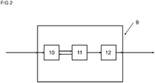
- the controller 9 comprises a filter 10 and a processing unit 11.
- the controller 9 advantageously also comprises an output unit 12.
- the filter 10 of the controller 9 is in operative communication with the flow sensor 5.
- the filter 10 reads analog and/or digital signals from the flow sensor 5.
- the filter 10 is a low-pass filter having a cutoff frequency.
- the cutoff frequency is an inverse of the time constant of the filter 10. At the cutoff frequency of the filter advantageously reduces signal amplitude by half (3 decibels). It is also envisaged that the filter 10 is a moving average filter.
- the filter 10 comprises an analog-to-digital converter. That is, the filter 10 receives analog signals from the flow sensor 5 and converts these analog signals into digital representations. The filter 10 subsequently transmits the digital representation to the processing unit 11.
- the analog-to-digital converter reads a number of signals per unit of time in accordance with its time constant.
- the analog-to-digital converter can, by way of non-limiting example, obtain signals at a time constant exceeding 0.1 Hertz and/or exceeding 1 Hertz and/or exceeding 10 Hertz. Higher time constants confer benefits in terms of improved resolution.
- the time constant of the analog-to-digital converter preferably is user programmable.
- the filter 10 is a digital filter. That is, the filter 10 receives digital signals indicative of flow.
- the digital filter 10 can be comprised in the controller 1 and/or in the flow sensor 5.
- the digital filter 10 reads a number of signals per unit of time in accordance with its time constant.
- the digital filter 10 can, by way of non-limiting example, obtain digital signals at a time constant below 10 seconds and/or below 1 second and/or below 0.1 seconds. Short time constants confer benefits in terms of improved resolution.
- the time constant of the digital filter 10 preferably is user programmable.
- a bidirectional data link is provided between the processing unit 11 and the filter 10.
- the processing unit 11 can use the bidirectional data link to control and/or to set the time constant of the filter 10. It is also envisaged that the processing unit 11 harnesses the bidirectional data link to instruct the filter 10 to deliver an instantaneous signal.
- the bidirectional data link also affords transmission of signals indicative of flow from the filter 10 to the processing unit 11.
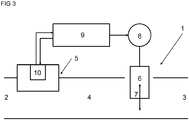
- FIG 3 shows a flow sensor 5 comprising a filter 10.
- the processing unit 11 will instruct the flow sensor 5 to deliver readings at a time constant.
- the processing unit 11 preferably relies on the bidirectional data link to transmit instructions such as a time constant to the flow sensor 5.
- the flow sensor 5 can, by way of non-limiting example, deliver readings via its filter 10 at a time constant below 10 seconds and/or below 1 second and/or below 0.1 seconds. Short time constants confer benefits in terms of improved resolution. It is also envisaged that the flow sensor 5 can be instructed to deliver an instantaneous reading and/or signal.
- the output unit 12 of controller 9 advantageously provides signal processing and/or amplification.
- the output unit 12 receives an instruction from the processing unit 11. That instruction can, by way of non-limiting example, be a digital representation of an electric current.
- the output unit 12 then provides a digital-to-analog converter to produce an analog value of the electric current.
- An amplifier is ideally provided to amplify the signal originating from the digital-to-analog converter to a signal suitable to drive the actuator 8.
- control valve (1) comprising:
- control valve (1) comprising:
- the first (position) signal indicative of the first position comprises a pulse-width modulated signal.
- the first (position) signal indicative of the first position comprises a signal produced by an inverter of the control valve (1).
- the output module (12) of the controller (9) can comprise an inverter.
- the first (position) signal indicative of the first position comprises a digital data packet transmitted via a digital communication bus of the control valve (1) in accordance with a digital communication bus protocol.
- the second (position) signal indicative of the second position comprises a pulse-width modulated signal.
- the second (position) signal indicative of the second position comprises a signal produced by an inverter of the control valve (1).
- the output module (12) of the controller (9) can comprise an inverter.
- the second (position) signal indicative of the second position comprises a digital data packet transmitted via a digital communication bus of the control valve (1) in accordance with a digital communication bus protocol.
- the filter (10) is in operative communication with the sensor (5).
- the filter (10) is preferably configured to continuously and/or repeatedly record and/or sample parameter signals originating from the sensor (5).
- the filter (10) is preferably configured to continuously and/or repeatedly record and/or sample parameter signals originating from the sensor (5).
- the actuator (8) preferably is mechanically coupled to the throttle (6). Ideally, the actuator (8) is directly mechanically coupled to the throttle (6).
- the actuator (8) can, by way of non-limiting example, be directly mechanically coupled to the throttle (6) using a valve stem and/or using a valve shaft.
- the throttle (6) advantageously is a displaceable throttle (6).
- the throttle (6) is displaceable inside the fluid path (4). It is envisaged that the throttle (6) acts on a flow of a fluid through the fluid path (4).
- the throttle (6) is selectively displaceable between a first position of the throttle (6) inside the fluid path (4) and a second position of the throttle (6) inside the fluid path (4). It is envisaged that at least one of
- the fluid path (4) comprises a fluid channel and/or a flow channel and/or a flow conduit.
- the throttle (6) is selectively displaceable in the fluid path (4) between a first and a second position.
- the present disclosure also teaches any of the aforementioned control valves (1), wherein the disable signal causes the filter (10) to (instantly) stop filtering parameter signals originating from the sensor (5) and causes the filter (10) to (directly) forward parameter signals originating from the sensor (5) to the controller (9).
- the present disclosure also teaches any of the aforementioned control valves (1), wherein the disable signal causes the filter (10) to (instantly) stop filtering parameter signals originating from the sensor (5) and causes the filter (10) to directly transmit parameter signals as originating from the sensor (5) to the controller (9).
- the present disclosure further teaches any of the aforementioned control valves (1), wherein the time constant of the filter (10) is a programmable time constant; and wherein the time constant signal causes the filter (10) to decrease its programmable time constant.
- the present disclosure yet further teaches any of the aforementioned control valves (1), wherein the time constant signal is indicative of a changed time constant; and wherein the time constant signal causes the filter (10) to set its time constant to the changed time constant.
- the present disclosure yet further teaches any of the aforementioned control valves (1), wherein the time constant signal is indicative of a changed time constant; and wherein the time constant signal causes the filter (10) to set its time constant in accordance with the changed time constant.
- the present disclosure yet further teaches any of the aforementioned control valves (1), wherein the time constant signal is indicative of a changed time constant; and wherein the time constant signal causes the filter (10) to set its time constant as a function of the changed time constant.
- the filter (10) comprises a low-pass filter having a cutoff frequency, the cutoff frequency being an inverse of the time constant of the filter (10).
- the present disclosure yet further teaches any of the aforementioned control valves (1), wherein the filter (10) is a low-pass filter having a cutoff frequency, the cutoff frequency being an inverse of the time constant of the filter (10).
- the present disclosure still further teaches any of the aforementioned control valves (1), wherein at the cutoff frequency the filter (10) is configured to reduce amplitudes of parameter signals by half.
- the present disclosure still further teaches any of the aforementioned control valves (1), wherein at the cutoff frequency the low-pass filter is configured to reduce amplitudes of parameter signals by half.
- controller (9) is configured to:
- the second position signal is transmitted at least 100 milliseconds or at least 200 milliseconds or at least 500 milliseconds or at least 1 second or at least 2 seconds or at least 5 seconds or at least 10 seconds after transmission of the first position signal.
- the present disclosure still also teaches any of the aforementioned control valves (1), wherein the filter (10) comprises an analog-to-digital converter, the analog-to-digital converter being in operative communication with the sensor (5).
- the filter (10) is configured to transmit parameter signals indicative of the one or more parameters originating from the sensor (5) to the controller (9) at time intervals defined by a time constant of the filter (10) and/or of the filter.
- the controller (9) advantageously comprises a microcontroller and the analog-to-digital converter, the microcontroller and the analog-to-digital converter both being arranged on a single system-on-a-chip.
- the filter (10) comprises a general-purpose input interface and/or a general-purpose input/output interface.
- the present disclosure still further teaches any of the aforementioned control valves (1), wherein the sensor comprises a flow sensor (5); and wherein the flow sensor (5) is arranged to record one or more parameters indicative of a flow rate through the fluid path (4).
- the senor (5) is a flow sensor such as a mass flow sensor and/or a volumetric flow sensor. It is also envisaged that the sensor (5) comprises a flow sensor such as a mass flow sensor and/or a volumetric flow sensor.
- the present disclosure further teaches any of the aforementioned control valves (1), wherein the sensor (5) comprises the filter (10) .
- controller (9) comprises the filter (10).
- the controller (9) physically comprises the filter (10).
- the sensor (5) physically comprises the filter (10).
- control valve (1) comprises a digital communication bus; and wherein the controller (9) is in operative communication with at least one of the filter (10) or the actuator (8) via the digital communication bus and using a digital communication bus protocol.
- the controller (9) is in operative communication with the filter (10) and with the actuator (8) via the digital communication bus and using a digital communication bus protocol.
- the controller (9) is configured to transmit (direct current) electric power to the filter (10) and to the actuator (8) using the digital communication bus.
- the present disclosure yet further teaches a pressure independent control valve comprising any of the aforementioned control valves (1).
- an electronic pressure independent control valve comprises any of the aforementioned control valves (1).
- a regulated valve comprises any of the aforementioned control valves (1).
- a circuit for heating, ventilation and/or air conditioning comprises any of the aforementioned control valves (1).
- the present disclosure also teaches a method for controlling a valve (1), the valve (1) comprising a fluid path (4), a sensor (5) for sampling one or more parameters of a fluid flowing through the fluid path (4), a throttle (6) situated in the fluid path (4), an actuator (8) coupled to the throttle (6), the throttle (6) being selectively displaceable between a first and a second position, the valve (1) comprising a filter (10) having a time constant and being in operative communication with the sensor (5) and being configured to filter parameter signals indicative of the one or more parameters using the time constant; the method comprising the steps of:
- first and the second position signals are compared in terms of throttle (6) positions.
- the present disclosure still teaches a non-transitory, computer-readable medium containing a program which executes the steps of a method according to the present disclosure.
- the computer-readable medium contains instructions that when executed perform the steps and/or perform the method according to the present disclosure. It is also envisaged that the computer-readable medium is tangible.
- Any steps of a method according to the present disclosure may be embodied in hardware, in a software module executed by a processor, in a software module being executed using operating-system-level virtualization, in a cloud computing arrangement, or in a combination thereof.
- the software may include a firmware, a hardware driver run in the operating system, or an application program.
- the disclosure also relates to a computer program product for performing the operations presented herein. If implemented in software, the functions described may be stored as one or more instructions on a computer-readable medium.
- RAM random access memory
- ROM read only memory
- flash memory EPROM memory
- EEPROM memory electrically erasable programmable read-only memory
- registers a hard disk, a removable disk, other optical disks, or any available media that can be accessed by a computer or any other IT equipment and appliance.
Landscapes
- Physics & Mathematics (AREA)
- General Physics & Mathematics (AREA)
- Engineering & Computer Science (AREA)
- Automation & Control Theory (AREA)
- Indication Of The Valve Opening Or Closing Status (AREA)
- Flow Control (AREA)
Abstract
Description
- The present disclosure relates to an improved control valve. The present disclosure focuses on a control valve wherein the flow of a fluid is a function of the position of a throttle. More particularly, the control valve as disclosed herein anticipates changes in flow rates and adjusts a time constant accordingly.
- Flow control valves are commonly employed in HVAC (heating, ventilation, air conditioning) systems of structures. These systems typically circulate a fluid such as water through a plurality of conduits in order to provide heating or cooling. The purpose of a flow control valve is to achieve a controlled flow of a fluid through the conduits of the circuit.
- The amount of water flowing through the valve is substantially governed by the position of the throttle. The position of the throttle is typically set by an actuator. The actuator sets the position of the throttle in response to a signal from a controller.
- A flow sensor may be arranged in a fluid path of the valve to provide readings of flow rate through the fluid path. The controller may read signals indicative of a flow rate from the sensor. The controller may then adjust the position of the throttle in response to the flow rate signal.
- The European patent application
EP2937759A1 was filed on 4 April 2014 .EP2937759A1 was published on 28 October 2015. The patent applicationEP2937759A1 teaches a pressure regulated valve with avalve body 1, with aninlet port 2 and with anoutlet port 3. Apiston 9 is arranged in afluid path 4 extending between theinlet port 2 and theoutlet port 3. A spring 13 urges thepiston 9 to open thefluid path 4. A channel 15 connects theinlet port 2 to a first end of thepiston 9. The channel 15 is separated from theoutlet port 3 of the valve via a diaphragm 18. Due to the channel 15 and the diaphragm 18, thepiston 9 moves in response to different pressures applied at theinlet port 2 and at theoutlet port 3. - A European patent application
EP0377913A2 was filed on 9 June 1989 . The applicationEP0377913A2 was published on 18 July 1990.EP0377913A2 discloses an adaptive digital filter which is responsive to the rate of change of an input signal. The filter 22 ofEP0377913A2 connects to apressure sensor 10. A difference DeltaS is determined between a first signal and a second signal. If that difference DeltaS is below a threshold ΔLSB, the filter 22 will employ a maximum time constant K1 + K2. The time constant of the filter 22 will otherwise be adjusted downward as a function of the difference DeltaS between the first and the second signal. - A patent application
US2006/0245132A1 was filed on 27 April 2006 . The applicationUS2006/0245132A1 was published on 2 November 2006 .US2006/0245132A1 teaches a time constant automatic adjusting circuit, filter circuit system, and method of automatically adjusting time constant. According toUS2006/0245132A1 , a phase comparison circuit 102 compares the phase of an output signal with a phase of a clock signal. An output voltage of the phase comparison circuit 102 is compared to reference signals Vref1, Vref2, and Vrefn via differential amplifiers 103-1, 103-2, and 103-n. An up/down counter 104 collects the signals from the differential amplifiers 103-1, 103-2, and 103-n. The up/down counter 104 produces a counted bit signal as a function of these collected signals. Finally, a control circuit 105 controls a time constant of a filter circuit 101 in response to the counted bit signal produced by the up/down counter 104. - An international patent application
WO2007/27897A2 was filed on 27 April 2007 8 November 2007. WO2007/27897A2 - A patent application
US2017/43402A1 was filed on 30 May 2017 . The application was published on 30 November 2017.US2017/43402A1 teaches a flow rate control device. - An international patent application
WO2004/10234A2 was filed on 17 July 2003 WO2004/10234A2 - The present disclosure teaches a control valve that samples signals from a flow sensor as an actuator of the valve moves. The instant disclosure focuses on a control valve that samples signals in response to changes in valve stroke.
- The present disclosure leverages insight gained from rapid changes in fluid flow, where these changes are caused by a throttle changing its position. There is a need to record values of flow associated with changes in valve stroke. That way, insight can be gained into the dynamics of fluid flow in consequence of changes in valve stroke. The object can be achieved by increasing the rate at which flow values are sampled while moving the throttle. The object can also be achieved by measuring at least one instantaneous value of fluid flow while changing a position of the throttle.
- To that end, the instant disclosure provides a control valve comprising an inlet port, an outlet port, and a fluid path extending between the inlet port and the outlet port; a throttle situated in the fluid path, and an actuator coupled to the throttle, the throttle being selectively displaceable between a first and a second position; a sensor for sampling one or more parameters of a fluid flowing through the fluid path, a filter having a time constant and being in operative communication with the sensor and being configured to filter parameter signals indicative of the one or more parameters using the time constant; a controller in operative communication with the actuator and being in operative communication with the filter, the controller being configured to: transmit a first signal indicative of the first position to the actuator, the first signal causing the actuator to displace the throttle to the first position; transmit a second signal indicative of the second position to the actuator, the second signal causing the actuator to displace the throttle to the second position; compare the first signal and the second signal; if the first position is different from the second position, perform at least one of: transmit a time constant signal to the filter, the time constant signal causing the filter to change its time constant; or transmit a disable signal to the filter, the disable signal causing the filter to stop filtering parameter signals originating from the sensor.
- It is a related object of the present disclosure to record an instantaneous flow signal in response to a demand for such a signal and to make that instantaneous signal readily available at the controller of the control valve. The flow signal can then be readily processed by the controller.
- It is another object of the present disclosure to continuously sample flow values and to sample flow values faster in response to a change in valve position.
- It is also an object of the instant disclosure to make optimum use of the bandwidth of a communication link involving the sensor, the filter, and the controller. The communication link can actually be a communication bus and other entities can connect to the same communication bus. In order to not jam the communication bus, flow values are rapidly communicated over the bus only where necessary.
- It is also an object of the instant disclosure to make optimum use of the computation capacity of a microcontroller or of a microprocessor within the controller. The microcontroller or microprocessor may also process signals other than flow values. The control valve and the method described herein avoid unnecessary computations while there is little change in fluid flow.
- It is a further object of the present disclosure to harness commercially available sensors for some embodiments such as flow sensors producing analog signals in the ranges between
- 0 Volt and 2 Volts,
- 0 Volt and 3 Volts,
- 0 Volt and 3.3 Volts,
- 0 Volt and 5 Volts, or
- 0 Volt and 10 Volts, or
- 0 millliAmpere and 20 milliAmperes.
- It is still another object of the instant disclosure to provide a control valve that functions with constrained flow sensors, where such constrained flow sensors include analog-to-digital conversion as well as a (digital) communication interface. A constrained flow sensor may also comprise an energy harvesting circuit to secure supply with electric energy.
- It is yet another object of the present disclosure to limit within the control valve the number of components that are prone to failure. To that end, a single bus can be employed that passes both data and electric energy along the bus. Also an analog-to-digital converter can be employed that is arranged together with the microprocessor or microcontroller of the controller on the same system-on-a-chip.
- Various features will become apparent to those skilled in the art from the following detailed description of the disclosed non-limiting embodiments. The drawings that accompany the detailed description can be briefly described as follows:
-
FIG 1 is a schematic representation of a control valve according to this disclosure. -
FIG 2 shows details of a controller of the control valve. -
FIG 3 schematically illustrates a control valve wherein the flow sensor provides a filter. -
FIG 1 shows the various principal and optional components of thecontrol valve 1 of the instant disclosure. The control valve comprises openings forming aninlet port 2 and anoutlet port 3. Afluid path 4 extends between theinlet port 2 and theoutlet port 3. Theinlet port 2 and theoutlet port 3 allow flow of a fluid through the valve. In a preferred embodiment, the fluid is a liquid. In particularly preferred embodiment, the fluid flowing through the valve is water or a mixture containing water. - The
control valve 1 comprises aflow sensor 5 such as an ultrasonic flow meter and/or a vortex flow meter. Theflow sensor 5 is arranged to provide signals indicative of fluid flow through thefluid path 4. In an embodiment, theflow sensor 5 is a mass flow sensor such as a thermal mass flow sensor. Theflow sensor 5 advantageously projects into thefluid path 4. The thermalmass flow sensor 5 may, by way of non-limiting example, employ constant temperature anemometry and/or on constant power anemometry to measure flow. In another embodiment, theflow sensor 5 is a volumetric flow sensor. - The
valve 1 provides athrottle 6 such as a valve plug and/or a valve member of a ball valve and/or a disk of a butterfly valve. Thethrottle 6 is situated in thefluid path 4. Anarrow 7 shown inFIG 1 indicates movement of thethrottle 6. It is envisaged that thethrottle 6 projects into thefluid path 4. Thethrottle 6 can move between an open position affording fluid flow of a fluid and a closed position obturating thefluid path 4. It is envisaged that the open position of thethrottle 6 fully opens thefluid path 4. That is, a change in the fully open position of thethrottle 6 does not entail an increase in fluid flow through thevalve 1. Likewise, it is envisaged that the closed position obturating thefluid path 4 is a fully closed position. That is, a change in the fully closed position of thethrottle 6 does not entail a decrease in fluid flow through thevalve 1. - In an embodiment, the
throttle 6 is continuously movable between the open position and the closed position. In an alternate embodiment, thethrottle 6 moves between the open position and the closed position in discreet steps. - An
actuator 8 such as an electric motor and/or a piezoelectric actuator mechanically couples to thethrottle 6. According to an aspect of the instant disclosure, a valve shaft and/or a valve stem mechanically couples theactuator 8 and thethrottle 6. Also, a clutch may couple theactuator 8 and thethrottle 6. Theactuator 8 and thethrottle 6 are coupled such that theactuator 8 adjusts thethrottle 6 between the open position and the closed position. In an embodiment, theactuator 8 continuously moves thethrottle 6 between the open position and the closed position. In an alternate embodiment, theactuator 8 selectively moves thethrottle 6 between the open position and the closed position. Theactuator 8 can, by way of non-limiting example, shift avalve plug 6 and/or rotate avalve member 6 of a ball valve. Theactuator 8 can, by way of another non-limiting example, also rotate adisk 6 of a butterfly valve. - A
controller 9 having a processor such as a microcontroller or a microprocessor is also shown inFIG 1 . Thecontroller 9 connects to theflow sensor 5. The connection may afford unidirectional communication from theflow sensor 5 to thecontroller 9 or bidirectional communication between theunits - In a particular embodiment, the
controller 9 obtains analog signals from theflow sensor 5. The analog signals can, by way of non-limiting example, be signals such as 0 milliAmpere to 20 milliAmperes and/or 4 milliAmperes to 20 milliAmperes and/or 0 Volt to 2 Volts and/or 0 Volt to 3 Volts and/or 0 Volt to 3.3 Volts and/or 0 Volt to 5 Volts and/or 0 Volt to 10 Volts signals. The analog signals are converted into digital signals by an analog-to-digital converter and/or by a delta-sigma modulator of thecontroller 9. The analog-to-digital converter can be separate from the microprocessor or from the microcontroller of thecontroller 9. The analog-to-digital converter can also be arranged together with the microprocessor or microcontroller on the same system-on-a-chip.The delta-sigma modulator can be separate from the microprocessor or from the microcontroller of thecontroller 9. The delta-sigma modulator can also be arranged together with the microprocessor or microcontroller on the same system-on-a-chip. - In an alternate embodiment, the
controller 9 receives digital signals from theflow sensor 5. To that end, a communication bus such as a serial communication bus and/or a parallel communication bus may be employed. The skilled person envisages busses employing network cables as well as wireless busses. The communication bus ideally uses a serial communication bus protocol and/or a parallel communication bus protocol. A bus that is compatible with at least one of the standards - IEEE 802.3af:2003 and / or
- IEEE 802.3at:2009 and / or
- IEEE 802.3au:2006
- The
controller 9 also connects to theactuator 8. The connection may afford unidirectional communication from thecontroller 9 to theactuator 8 or bidirectional communication between theunits - In a particular embodiment, the
controller 9 transmits analog signals to theactuator 8. The analog signals can, by way of non-limiting example, be signals such as 0 milliAmpere to 20 milliAmperes and/or 4 milliAmperes to 20 milliAmperes and/or 0 Volt to 2 Volts and/or 0 Volt to 3 Volts and/or 0 Volt to 3.3 Volts and/or 0 Volt to 5 Volts signals. Thecontroller 9 advantageously comprises a digital-to-analog converter to produce these analog signals. The digital-to-analog converter can be separate from the microprocessor or from the microcontroller of thecontroller 9. The digital-to-analog converter can also be arranged together with the microprocessor or together with the microcontroller on the same system-on-a-chip. - In an alternate embodiment, the
controller 9 transmits digital signals to theactuator 8. To that end, a communication bus such as a serial communication bus and/or a parallel communication bus may be employed. The skilled person envisages busses employing network cables as well as wireless busses. The communication bus ideally uses a serial communication bus protocol and/or a parallel communication bus protocol. A bus that is compatible with at least one of the standards - IEEE 802.3af:2003 and / or
- IEEE 802.3at:2009 and / or
- IEEE 802.3au:2006
- Now referring to
FIG 2 , details of thecontroller 9 are illustrated. Thecontroller 9 comprises afilter 10 and aprocessing unit 11. Thecontroller 9 advantageously also comprises anoutput unit 12. - The
filter 10 of thecontroller 9 is in operative communication with theflow sensor 5. Thefilter 10 reads analog and/or digital signals from theflow sensor 5. It is envisaged that thefilter 10 is a low-pass filter having a cutoff frequency. The cutoff frequency is an inverse of the time constant of thefilter 10. At the cutoff frequency of the filter advantageously reduces signal amplitude by half (3 decibels). It is also envisaged that thefilter 10 is a moving average filter. - In an embodiment, the
filter 10 comprises an analog-to-digital converter. That is, thefilter 10 receives analog signals from theflow sensor 5 and converts these analog signals into digital representations. Thefilter 10 subsequently transmits the digital representation to theprocessing unit 11. The analog-to-digital converter reads a number of signals per unit of time in accordance with its time constant. The analog-to-digital converter can, by way of non-limiting example, obtain signals at a time constant exceeding 0.1 Hertz and/or exceeding 1 Hertz and/or exceeding 10 Hertz. Higher time constants confer benefits in terms of improved resolution. The time constant of the analog-to-digital converter preferably is user programmable. - In an alternate embodiment, the
filter 10 is a digital filter. That is, thefilter 10 receives digital signals indicative of flow. Thedigital filter 10 can be comprised in thecontroller 1 and/or in theflow sensor 5. - The
digital filter 10 reads a number of signals per unit of time in accordance with its time constant. Thedigital filter 10 can, by way of non-limiting example, obtain digital signals at a time constant below 10 seconds and/or below 1 second and/or below 0.1 seconds. Short time constants confer benefits in terms of improved resolution. The time constant of thedigital filter 10 preferably is user programmable. - A bidirectional data link is provided between the processing
unit 11 and thefilter 10. Theprocessing unit 11 can use the bidirectional data link to control and/or to set the time constant of thefilter 10. It is also envisaged that theprocessing unit 11 harnesses the bidirectional data link to instruct thefilter 10 to deliver an instantaneous signal. The bidirectional data link also affords transmission of signals indicative of flow from thefilter 10 to theprocessing unit 11. -
FIG 3 shows aflow sensor 5 comprising afilter 10. Where thefilter 10 is part of theflow sensor 5, theprocessing unit 11 will instruct theflow sensor 5 to deliver readings at a time constant. Theprocessing unit 11 preferably relies on the bidirectional data link to transmit instructions such as a time constant to theflow sensor 5. Theflow sensor 5 can, by way of non-limiting example, deliver readings via itsfilter 10 at a time constant below 10 seconds and/or below 1 second and/or below 0.1 seconds. Short time constants confer benefits in terms of improved resolution. It is also envisaged that theflow sensor 5 can be instructed to deliver an instantaneous reading and/or signal. - The
output unit 12 ofcontroller 9 advantageously provides signal processing and/or amplification. To that end, theoutput unit 12 receives an instruction from theprocessing unit 11. That instruction can, by way of non-limiting example, be a digital representation of an electric current. Theoutput unit 12 then provides a digital-to-analog converter to produce an analog value of the electric current. An amplifier is ideally provided to amplify the signal originating from the digital-to-analog converter to a signal suitable to drive theactuator 8. - As described in detail herein, the instant disclosure teaches a control valve (1) comprising:
- an inlet port (2), an outlet port (3), and a fluid path (4) extending between the inlet port (2) and the outlet port (3);
- a throttle (6) situated in the fluid path (4), and an actuator (8) coupled to the throttle (6), the throttle (6) being selectively displaceable between a first and a second position;
- a sensor (5) for sampling one or more parameters of a fluid flowing through the fluid path (4), a filter (10) having a time constant and being in operative communication with the sensor (5) and being configured to filter, using the time constant, parameter signals indicative of the one or more parameters;
- a controller (9) in operative communication with the actuator (8) and in operative communication with the filter (10), the controller (9) being configured to:
- transmit a first signal indicative of the first position to the actuator (8), the first signal causing the actuator (8) to displace the throttle (6) to the first position;
- transmit a second signal indicative of the second position to the actuator (8), the second signal causing the actuator (8) to displace the throttle (6) to the second position;
- compare the first signal and the second signal;
- if the first position is different from the second position:
transmit a time constant signal to the filter (10), the time constant signal causing the filter (10) to change its time constant.
- The instant disclosure also teaches a control valve (1) comprising:
- an inlet port (2), an outlet port (3), and a fluid path (4) extending between the inlet port (2) and the outlet port (3);
- a throttle (6) situated in the fluid path (4), and an actuator (8) coupled to the throttle (6), the throttle (6) being selectively displaceable between a first and a second position;
- a sensor (5) for sampling one or more parameters of a fluid flowing through the fluid path (4), a filter (10) having a time constant and being in operative communication with the sensor (5) and being configured to filter parameter signals indicative of the one or more parameters using the time constant;
- a controller (9) in operative communication with the actuator (8) and in operative communication with the filter (10), the controller (9) being configured to:
- transmit a first signal indicative of the first position to the actuator (8), the first signal causing the actuator (8) to displace the throttle (6) to the first position;
- transmit a second signal indicative of the second position to the actuator (8), the second signal causing the actuator (8) to displace the throttle (6) to the second position;
- compare the first signal and the second signal;
- if the first position is different from the second position:
transmit a disable signal to the filter (10), the disable signal causing the filter (10) to stop filtering parameter signals originating from the sensor (5).
- According to an aspect of the present disclosure, the first (position) signal indicative of the first position comprises a pulse-width modulated signal. According to another aspect of the present disclosure, the first (position) signal indicative of the first position comprises a signal produced by an inverter of the control valve (1). To that end, the output module (12) of the controller (9) can comprise an inverter. According to yet another aspect of the present disclosure, the first (position) signal indicative of the first position comprises a digital data packet transmitted via a digital communication bus of the control valve (1) in accordance with a digital communication bus protocol. According to an aspect of the present disclosure, the second (position) signal indicative of the second position comprises a pulse-width modulated signal. According to another aspect of the present disclosure, the second (position) signal indicative of the second position comprises a signal produced by an inverter of the control valve (1). To that end, the output module (12) of the controller (9) can comprise an inverter. According to yet another aspect of the present disclosure, the second (position) signal indicative of the second position comprises a digital data packet transmitted via a digital communication bus of the control valve (1) in accordance with a digital communication bus protocol.
- In an embodiment, the filter (10) is in operative communication with the sensor (5). The filter (10) is preferably configured to continuously and/or repeatedly record and/or sample parameter signals originating from the sensor (5). The filter (10) is preferably configured to continuously and/or repeatedly record and/or sample parameter signals originating from the sensor (5).
- The actuator (8) preferably is mechanically coupled to the throttle (6). Ideally, the actuator (8) is directly mechanically coupled to the throttle (6). The actuator (8) can, by way of non-limiting example, be directly mechanically coupled to the throttle (6) using a valve stem and/or using a valve shaft.
- The throttle (6) advantageously is a displaceable throttle (6). Ideally, the throttle (6) is displaceable inside the fluid path (4). It is envisaged that the throttle (6) acts on a flow of a fluid through the fluid path (4). In an embodiment, the throttle (6) is selectively displaceable between a first position of the throttle (6) inside the fluid path (4) and a second position of the throttle (6) inside the fluid path (4). It is envisaged that at least one of
- the first position of the throttle (6) or
- the second position of the throttle (6)
- It is envisaged that the fluid path (4) comprises a fluid channel and/or a flow channel and/or a flow conduit.
- It is also envisaged that the throttle (6) is selectively displaceable in the fluid path (4) between a first and a second position.
- The present disclosure also teaches any of the aforementioned control valves (1), wherein the disable signal causes the filter (10) to (instantly) stop filtering parameter signals originating from the sensor (5) and causes the filter (10) to (directly) forward parameter signals originating from the sensor (5) to the controller (9).
- The present disclosure also teaches any of the aforementioned control valves (1), wherein the disable signal causes the filter (10) to (instantly) stop filtering parameter signals originating from the sensor (5) and causes the filter (10) to directly transmit parameter signals as originating from the sensor (5) to the controller (9).
- The present disclosure further teaches any of the aforementioned control valves (1),
wherein the time constant of the filter (10) is a programmable time constant; and
wherein the time constant signal causes the filter (10) to decrease its programmable time constant. - The present disclosure yet further teaches any of the aforementioned control valves (1),
wherein the time constant signal is indicative of a changed time constant; and
wherein the time constant signal causes the filter (10) to set its time constant to the changed time constant. - The present disclosure yet further teaches any of the aforementioned control valves (1),
wherein the time constant signal is indicative of a changed time constant; and
wherein the time constant signal causes the filter (10) to set its time constant in accordance with the changed time constant. - The present disclosure yet further teaches any of the aforementioned control valves (1),
wherein the time constant signal is indicative of a changed time constant; and
wherein the time constant signal causes the filter (10) to set its time constant as a function of the changed time constant. - The present disclosure yet further teaches any of the aforementioned control valves (1), wherein the filter (10) comprises a low-pass filter having a cutoff frequency, the cutoff frequency being an inverse of the time constant of the filter (10).
- The present disclosure yet further teaches any of the aforementioned control valves (1), wherein the filter (10) is a low-pass filter having a cutoff frequency, the cutoff frequency being an inverse of the time constant of the filter (10).
- The present disclosure still further teaches any of the aforementioned control valves (1), wherein at the cutoff frequency the filter (10) is configured to reduce amplitudes of parameter signals by half.
- The present disclosure still further teaches any of the aforementioned control valves (1), wherein at the cutoff frequency the low-pass filter is configured to reduce amplitudes of parameter signals by half.
- The present disclosure still further teaches any of the aforementioned control valves (1), wherein the controller (9) is configured to:
- transmit a first position signal indicative of the first position to the actuator (8), the first position signal causing the actuator (8) to displace the throttle (6) to the first position; and
- after transmission of the first position signal, transmit a second position signal indicative of the second position to the actuator (8), the second position signal causing the actuator (8) to displace the throttle (6) to the second position.
- It is envisaged that the second position signal is transmitted at least 100 milliseconds or at least 200 milliseconds or at least 500 milliseconds or at least 1 second or at least 2 seconds or at least 5 seconds or at least 10 seconds after transmission of the first position signal.
- The present disclosure still also teaches any of the aforementioned control valves (1), wherein the filter (10) comprises an analog-to-digital converter, the analog-to-digital converter being in operative communication with the sensor (5).
- In an embodiment, the filter (10) is configured to transmit parameter signals indicative of the one or more parameters originating from the sensor (5) to the controller (9) at time intervals defined by a time constant of the filter (10) and/or of the filter.
- The controller (9) advantageously comprises a microcontroller and the analog-to-digital converter, the microcontroller and the analog-to-digital converter both being arranged on a single system-on-a-chip.
- In an embodiment, the filter (10) comprises a general-purpose input interface and/or a general-purpose input/output interface.
- The present disclosure still further teaches any of the aforementioned control valves (1),
wherein the sensor comprises a flow sensor (5); and
wherein the flow sensor (5) is arranged to record one or more parameters indicative of a flow rate through the fluid path (4). - It is envisaged that the sensor (5) is a flow sensor such as a mass flow sensor and/or a volumetric flow sensor. It is also envisaged that the sensor (5) comprises a flow sensor such as a mass flow sensor and/or a volumetric flow sensor.
- The present disclosure further teaches any of the aforementioned control valves (1), wherein the sensor (5) comprises the filter (10) .
- The present disclosure still further teaches any of the aforementioned control valves (1), wherein the controller (9) comprises the filter (10).
- In an embodiment, the controller (9) physically comprises the filter (10). In an alternate embodiment, the sensor (5) physically comprises the filter (10).
- The present disclosure also teaches any of the aforementioned control valves (1),
wherein the control valve (1) comprises a digital communication bus; and
wherein the controller (9) is in operative communication with at least one of
the filter (10) or
the actuator (8)
via the digital communication bus and using a digital communication bus protocol. - In an embodiment, the controller (9) is in operative communication with the filter (10) and with the actuator (8) via the digital communication bus and using a digital communication bus protocol.
- The present disclosure still further teaches the aforementioned control valve (1),
- wherein the digital communication bus is configured to transmit data signals along with electric power; and
- wherein the controller (9) is configured to transmit electric power to at least one of
- the filter (10) or
- the actuator (8)
- Ideally, the controller (9) is configured to transmit (direct current) electric power to the filter (10) and to the actuator (8) using the digital communication bus.
- The present disclosure yet further teaches a pressure independent control valve comprising any of the aforementioned control valves (1).
- According to an aspect of the present disclosure, an electronic pressure independent control valve comprises any of the aforementioned control valves (1). According to another aspect of the present disclosure, a regulated valve comprises any of the aforementioned control valves (1). According to yet another aspect of the present disclosure, a circuit for heating, ventilation and/or air conditioning comprises any of the aforementioned control valves (1).
- The present disclosure also teaches a method for controlling a valve (1), the valve (1) comprising a fluid path (4), a sensor (5) for sampling one or more parameters of a fluid flowing through the fluid path (4), a throttle (6) situated in the fluid path (4), an actuator (8) coupled to the throttle (6), the throttle (6) being selectively displaceable between a first and a second position, the valve (1) comprising a filter (10) having a time constant and being in operative communication with the sensor (5) and being configured to filter parameter signals indicative of the one or more parameters using the time constant;
the method comprising the steps of: - transmitting a first position signal indicative of the first position to the actuator (8), the first position signal causing the actuator (8) to displace the throttle (6) to the first position;
- transmitting a second position signal indicative of the second position to the actuator (8), the second position signal causing the actuator (8) to displace the throttle (6) to the second position;
- comparing the first and the second position signals;
- if the first position is different from the second position, performing at least one of:
- transmitting a time constant signal to the filter (10), the time constant signal causing the filter (10) to change its time constant; or
- transmitting a disable signal to the filter (10), the disable signal causing the filter (10) to stop filtering parameter signals originating from the sensor (5).
- It is envisaged that the first and the second position signals are compared in terms of throttle (6) positions.
- The present disclosure still teaches a non-transitory, computer-readable medium containing a program which executes the steps of a method according to the present disclosure.
- It is envisaged that the computer-readable medium contains instructions that when executed perform the steps and/or perform the method according to the present disclosure. It is also envisaged that the computer-readable medium is tangible.
- Any steps of a method according to the present disclosure may be embodied in hardware, in a software module executed by a processor, in a software module being executed using operating-system-level virtualization, in a cloud computing arrangement, or in a combination thereof. The software may include a firmware, a hardware driver run in the operating system, or an application program. Thus, the disclosure also relates to a computer program product for performing the operations presented herein. If implemented in software, the functions described may be stored as one or more instructions on a computer-readable medium. Some examples of storage media that may be used include random access memory (RAM), read only memory (ROM), flash memory, EPROM memory, EEPROM memory, registers, a hard disk, a removable disk, other optical disks, or any available media that can be accessed by a computer or any other IT equipment and appliance.
- It should be understood that the foregoing relates only to certain embodiments of the disclosure and that numerous changes may be made therein without departing from the scope of the disclosure as defined by the following claims. It should also be understood that the disclosure is not restricted to the illustrated embodiments and that various modifications can be made within the scope of the following claims.
-
- 1
- valve
- 2
- inlet port
- 3
- outlet port
- 4
- fluid path
- 5
- flow sensor
- 6
- throttle
- 7
- directions of movement of the throttle
- 8
- actuator
- 9
- controller
- 10
- filter
- 11
- processing unit
- 12
- output unit
Claims (15)
- A control valve (1) comprising:an inlet port (2), an outlet port (3), and a fluid path (4) extending between the inlet port (2) and the outlet port (3);a throttle (6) situated in the fluid path (4), and an actuator (8) coupled to the throttle (6), the throttle (6) being selectively displaceable between a first and a second position;a sensor (5) for sampling one or more parameters of a fluid flowing through the fluid path (4), a filter (10) having a time constant and being in operative communication with the sensor (5) and being configured to filter, using the time constant, parameter signals indicative of the one or more parameters;a controller (9) in operative communication with the actuator (8) and in operative communication with the filter (10), the controller (9) being configured to:transmit a first signal indicative of the first position to the actuator (8), the first signal causing the actuator (8) to displace the throttle (6) to the first position;transmit a second signal indicative of the second position to the actuator (8), the second signal causing the actuator (8) to displace the throttle (6) to the second position;compare the first signal and the second signal;characterized in thatif the first position is different from the second position, perform at least one of:transmit a time constant signal to the filter (10), the time constant signal causing the filter (10) to change its time constant; ortransmit a disable signal to the filter (10), the disable signal causing the filter (10) to stop filtering parameter signals originating from the sensor (5) and to directly forward parameter signals originating from the sensor (5) to the controller (9).
- The control valve (1) according to claim 1, wherein the disable signal causes the filter (10) to stop filtering parameter signals originating from the sensor (5) and causes the filter (10) to directly transmit parameter signals as originating from the sensor (5) to the controller (9).
- The control valve (1) according to any of the claims 1 to 2,
wherein the time constant of the filter (10) is a programmable time constant; and
wherein the time constant signal causes the filter (10) to decrease its programmable time constant. - The control valve (1) according any of the claims 1 to 3,
wherein the time constant signal is indicative of a changed time constant; and
wherein the time constant signal causes the filter (10) to set its time constant to the changed time constant. - The control valve (1) according to any of the claims 1 to 4, wherein the filter (10) comprises a low-pass filter having a cutoff frequency, the cutoff frequency being an inverse of the time constant of the filter (10).
- The control valve (1) according to claim 5, wherein at the cutoff frequency the filter (10) is configured to reduce amplitudes of parameter signals by half.
- The control valve (1) according to any of the claims 1 to 6, wherein the controller (9) is configured to:transmit a first position signal indicative of the first position to the actuator (8), the first position signal causing the actuator (8) to displace the throttle (6) to the first position; andafter transmission of the first position signal, transmit a second position signal indicative of the second position to the actuator (8), the second position signal causing the actuator (8) to displace the throttle (6) to the second position.
- The control valve (1) according to any of the claims 1 to 7, wherein the sensor comprises a flow sensor (5); and wherein the flow sensor (5) is arranged to record one or more parameters indicative of a flow rate through the fluid path (4).
- The control valve (1) according to any of the claims 1 to 8, wherein the sensor (5) comprises the filter (10).
- The control valve (1) according to any of the claims 1 to 8, wherein the controller (9) comprises the filter (10).
- The control valve (1) according to any of the claims 1 to 10,
wherein the control valve (1) comprises a digital communication bus; and
wherein the controller (9) is in operative communication with at least one of
the filter (10) or
the actuator (8)
via the digital communication bus and using a digital communication bus protocol. - The control valve (1) according to claim 11,wherein the digital communication bus is configured to transmit data signals along with electric power; andwherein the controller (9) is configured to transmit electric power to at least one ofthe filter (10) orthe actuator (8)using the digital communication bus.
- A pressure independent control valve comprising a control valve (1) according to any of the claims 1 to 12.
- A method for controlling a valve (1), the valve (1) comprising a fluid path (4), a sensor (5) for sampling one or more parameters of a fluid flowing through the fluid path (4), a throttle (6) situated in the fluid path (4), an actuator (8) coupled to the throttle (6), the throttle (6) being selectively displaceable between a first and a second position, the valve (1) comprising a filter (10) having a time constant and being in operative communication with the sensor (5) and being configured to filter parameter signals indicative of the one or more parameters using the time constant;
the method comprising the steps of:transmitting a first position signal indicative of the first position to the actuator (8), the first position signal causing the actuator (8) to displace the throttle (6) to the first position;transmitting a second position signal indicative of the second position to the actuator (8), the second position signal causing the actuator (8) to displace the throttle (6) to the second position;comparing the first and the second position signals;characterized in thatif the first position is different from the second position, performing at least one of:transmitting a time constant signal to the filter (10), the time constant signal causing the filter (10) to change its time constant; ortransmitting a disable signal to the filter (10), the disable signal causing the filter (10) to stop filtering parameter signals originating from the sensor (5) and to directly forward parameter signals originating from the sensor (5) to the controller (9). - A non-transitory, computer-readable medium containing a program which executes the steps of claim 14.
Applications Claiming Priority (1)
| Application Number | Priority Date | Filing Date | Title |
|---|---|---|---|
| EP19154639 | 2019-01-30 |
Publications (2)
| Publication Number | Publication Date |
|---|---|
| EP3690592A1 true EP3690592A1 (en) | 2020-08-05 |
| EP3690592B1 EP3690592B1 (en) | 2021-04-28 |
Family
ID=65279413
Family Applications (1)
| Application Number | Title | Priority Date | Filing Date |
|---|---|---|---|
| EP19186663.1A Active EP3690592B1 (en) | 2019-01-30 | 2019-07-17 | Control valve |
Country Status (2)
| Country | Link |
|---|---|
| EP (1) | EP3690592B1 (en) |
| DK (1) | DK3690592T3 (en) |
Citations (8)
| Publication number | Priority date | Publication date | Assignee | Title |
|---|---|---|---|---|
| EP0377913A2 (en) | 1989-01-11 | 1990-07-18 | The Boeing Company | Adaptive digital filter which is responsive to the rate of change of an input signal |
| WO2004010234A2 (en) | 2002-07-19 | 2004-01-29 | Celerity Group, Inc. | Methods and apparatus for pressure compensation in a mass flow controller |
| US20060245132A1 (en) | 2005-04-28 | 2006-11-02 | Kabushiki Kaisha Toshiba | Time constant automatic adjusting circuit, filter circuit system, and method of automatically adjusting time constant |
| WO2007027897A1 (en) | 2005-08-31 | 2007-03-08 | Kimberly-Clark Worldwide, Inc. | System for disposal of refus |
| WO2007127897A2 (en) * | 2006-04-28 | 2007-11-08 | Advanced Energy Industries, Inc. | Adaptive response time closed loop control algorithm |
| EP2937759A1 (en) | 2014-04-24 | 2015-10-28 | Siemens Schweiz AG | Pressure independent control valve |
| US20170043402A1 (en) | 2014-04-29 | 2017-02-16 | Saint Jean Industries | Method for the production of parts made from metal or metal matrix composite and resulting from additive manufacturing followed by an operation involving the forging of said parts |
| US20170343402A1 (en) * | 2016-05-31 | 2017-11-30 | Horiba Stec, Co., Ltd. | Flow rate control device |
-
2019
- 2019-07-17 DK DK19186663.1T patent/DK3690592T3/en active
- 2019-07-17 EP EP19186663.1A patent/EP3690592B1/en active Active
Patent Citations (8)
| Publication number | Priority date | Publication date | Assignee | Title |
|---|---|---|---|---|
| EP0377913A2 (en) | 1989-01-11 | 1990-07-18 | The Boeing Company | Adaptive digital filter which is responsive to the rate of change of an input signal |
| WO2004010234A2 (en) | 2002-07-19 | 2004-01-29 | Celerity Group, Inc. | Methods and apparatus for pressure compensation in a mass flow controller |
| US20060245132A1 (en) | 2005-04-28 | 2006-11-02 | Kabushiki Kaisha Toshiba | Time constant automatic adjusting circuit, filter circuit system, and method of automatically adjusting time constant |
| WO2007027897A1 (en) | 2005-08-31 | 2007-03-08 | Kimberly-Clark Worldwide, Inc. | System for disposal of refus |
| WO2007127897A2 (en) * | 2006-04-28 | 2007-11-08 | Advanced Energy Industries, Inc. | Adaptive response time closed loop control algorithm |
| EP2937759A1 (en) | 2014-04-24 | 2015-10-28 | Siemens Schweiz AG | Pressure independent control valve |
| US20170043402A1 (en) | 2014-04-29 | 2017-02-16 | Saint Jean Industries | Method for the production of parts made from metal or metal matrix composite and resulting from additive manufacturing followed by an operation involving the forging of said parts |
| US20170343402A1 (en) * | 2016-05-31 | 2017-11-30 | Horiba Stec, Co., Ltd. | Flow rate control device |
Also Published As
| Publication number | Publication date |
|---|---|
| DK3690592T3 (en) | 2021-07-05 |
| EP3690592B1 (en) | 2021-04-28 |
Similar Documents
| Publication | Publication Date | Title |
|---|---|---|
| EP3428767B1 (en) | Control gain automation | |
| US8261733B2 (en) | Modulating gas furnace | |
| EP4682664A2 (en) | Flow control device for an hvac fluid transportation system | |
| CA2727779A1 (en) | Method for the hydraulic balancing and regulation of a heating or cooling system and balancing and regulating valve therefor | |
| CN105158504A (en) | Wind speed and wind pressure sensor for range hood and range hood | |
| EP3690592B1 (en) | Control valve | |
| US11614757B2 (en) | Estimating a maximum flow through a heat exchanger | |
| KR20150088640A (en) | Compressor system and method for controlling thereof | |
| CN103116367A (en) | Automatic control method and system for tail gate water level in river model | |
| CN110736526B (en) | High-temperature gas flowmeter calibration device and method for liquid oxygen kerosene engine | |
| CN110641675A (en) | Variable working condition low-noise control device and control method for ship cooling system | |
| CN211319089U (en) | Reaction kettle temperature control system | |
| CN206710092U (en) | Performance Test Bench of Hydraulic Torque Converter | |
| CN207584168U (en) | The adjusting valve actuator integrated apparatus of accurate flow control | |
| CN111077923B (en) | Air supply system of airborne blasting device and control method thereof | |
| CN105782509B (en) | The controlled valve of mixed cold and hot water and the method for operating the valve | |
| CN109309464A (en) | A kind of servo response bandwidth test method and system | |
| CN203730887U (en) | Electric adjusting valve | |
| CN209444837U (en) | A kind of Internet of Things equalized temperature valve and its heat supply secondary network regulating system | |
| CN106643919B (en) | Flue gas flow measuring method and measuring device | |
| CN115097882A (en) | Constant temperature control system of medical blood transfusion and infusion heater | |
| CN117724382A (en) | An intelligent fan impurity removal system for sugarcane combine harvesters | |
| CN201461492U (en) | Temperature-sensitive self-adjusting speed fan | |
| CN213983514U (en) | A new type of boiler controller | |
| CN202132593U (en) | Temperature and pressure protection type flow controller |
Legal Events
| Date | Code | Title | Description |
|---|---|---|---|
| PUAI | Public reference made under article 153(3) epc to a published international application that has entered the european phase |
Free format text: ORIGINAL CODE: 0009012 |
|
| STAA | Information on the status of an ep patent application or granted ep patent |
Free format text: STATUS: REQUEST FOR EXAMINATION WAS MADE |
|
| 17P | Request for examination filed |
Effective date: 20200205 |
|
| AK | Designated contracting states |
Kind code of ref document: A1 Designated state(s): AL AT BE BG CH CY CZ DE DK EE ES FI FR GB GR HR HU IE IS IT LI LT LU LV MC MK MT NL NO PL PT RO RS SE SI SK SM TR |
|
| AX | Request for extension of the european patent |
Extension state: BA ME |
|
| GRAP | Despatch of communication of intention to grant a patent |
Free format text: ORIGINAL CODE: EPIDOSNIGR1 |
|
| STAA | Information on the status of an ep patent application or granted ep patent |
Free format text: STATUS: GRANT OF PATENT IS INTENDED |
|
| INTG | Intention to grant announced |
Effective date: 20210126 |
|
| GRAS | Grant fee paid |
Free format text: ORIGINAL CODE: EPIDOSNIGR3 |
|
| GRAA | (expected) grant |
Free format text: ORIGINAL CODE: 0009210 |
|
| STAA | Information on the status of an ep patent application or granted ep patent |
Free format text: STATUS: THE PATENT HAS BEEN GRANTED |
|
| AK | Designated contracting states |
Kind code of ref document: B1 Designated state(s): AL AT BE BG CH CY CZ DE DK EE ES FI FR GB GR HR HU IE IS IT LI LT LU LV MC MK MT NL NO PL PT RO RS SE SI SK SM TR |
|
| REG | Reference to a national code |
Ref country code: GB Ref legal event code: FG4D |
|
| REG | Reference to a national code |
Ref country code: CH Ref legal event code: EP |
|
| REG | Reference to a national code |
Ref country code: AT Ref legal event code: REF Ref document number: 1387804 Country of ref document: AT Kind code of ref document: T Effective date: 20210515 |
|
| REG | Reference to a national code |
Ref country code: DE Ref legal event code: R096 Ref document number: 602019004210 Country of ref document: DE |
|
| REG | Reference to a national code |
Ref country code: IE Ref legal event code: FG4D |
|
| REG | Reference to a national code |
Ref country code: DK Ref legal event code: T3 Effective date: 20210701 |
|
| REG | Reference to a national code |
Ref country code: NL Ref legal event code: FP |
|
| REG | Reference to a national code |
Ref country code: SE Ref legal event code: TRGR |
|
| REG | Reference to a national code |
Ref country code: LT Ref legal event code: MG9D |
|
| REG | Reference to a national code |
Ref country code: AT Ref legal event code: MK05 Ref document number: 1387804 Country of ref document: AT Kind code of ref document: T Effective date: 20210428 |
|
| PG25 | Lapsed in a contracting state [announced via postgrant information from national office to epo] |
Ref country code: AT Free format text: LAPSE BECAUSE OF FAILURE TO SUBMIT A TRANSLATION OF THE DESCRIPTION OR TO PAY THE FEE WITHIN THE PRESCRIBED TIME-LIMIT Effective date: 20210428 Ref country code: BG Free format text: LAPSE BECAUSE OF FAILURE TO SUBMIT A TRANSLATION OF THE DESCRIPTION OR TO PAY THE FEE WITHIN THE PRESCRIBED TIME-LIMIT Effective date: 20210728 Ref country code: FI Free format text: LAPSE BECAUSE OF FAILURE TO SUBMIT A TRANSLATION OF THE DESCRIPTION OR TO PAY THE FEE WITHIN THE PRESCRIBED TIME-LIMIT Effective date: 20210428 Ref country code: HR Free format text: LAPSE BECAUSE OF FAILURE TO SUBMIT A TRANSLATION OF THE DESCRIPTION OR TO PAY THE FEE WITHIN THE PRESCRIBED TIME-LIMIT Effective date: 20210428 Ref country code: LT Free format text: LAPSE BECAUSE OF FAILURE TO SUBMIT A TRANSLATION OF THE DESCRIPTION OR TO PAY THE FEE WITHIN THE PRESCRIBED TIME-LIMIT Effective date: 20210428 |
|
| PG25 | Lapsed in a contracting state [announced via postgrant information from national office to epo] |
Ref country code: IS Free format text: LAPSE BECAUSE OF FAILURE TO SUBMIT A TRANSLATION OF THE DESCRIPTION OR TO PAY THE FEE WITHIN THE PRESCRIBED TIME-LIMIT Effective date: 20210828 Ref country code: GR Free format text: LAPSE BECAUSE OF FAILURE TO SUBMIT A TRANSLATION OF THE DESCRIPTION OR TO PAY THE FEE WITHIN THE PRESCRIBED TIME-LIMIT Effective date: 20210729 Ref country code: LV Free format text: LAPSE BECAUSE OF FAILURE TO SUBMIT A TRANSLATION OF THE DESCRIPTION OR TO PAY THE FEE WITHIN THE PRESCRIBED TIME-LIMIT Effective date: 20210428 Ref country code: PL Free format text: LAPSE BECAUSE OF FAILURE TO SUBMIT A TRANSLATION OF THE DESCRIPTION OR TO PAY THE FEE WITHIN THE PRESCRIBED TIME-LIMIT Effective date: 20210428 Ref country code: NO Free format text: LAPSE BECAUSE OF FAILURE TO SUBMIT A TRANSLATION OF THE DESCRIPTION OR TO PAY THE FEE WITHIN THE PRESCRIBED TIME-LIMIT Effective date: 20210728 Ref country code: PT Free format text: LAPSE BECAUSE OF FAILURE TO SUBMIT A TRANSLATION OF THE DESCRIPTION OR TO PAY THE FEE WITHIN THE PRESCRIBED TIME-LIMIT Effective date: 20210830 Ref country code: RS Free format text: LAPSE BECAUSE OF FAILURE TO SUBMIT A TRANSLATION OF THE DESCRIPTION OR TO PAY THE FEE WITHIN THE PRESCRIBED TIME-LIMIT Effective date: 20210428 |
|
| PG25 | Lapsed in a contracting state [announced via postgrant information from national office to epo] |
Ref country code: SK Free format text: LAPSE BECAUSE OF FAILURE TO SUBMIT A TRANSLATION OF THE DESCRIPTION OR TO PAY THE FEE WITHIN THE PRESCRIBED TIME-LIMIT Effective date: 20210428 Ref country code: EE Free format text: LAPSE BECAUSE OF FAILURE TO SUBMIT A TRANSLATION OF THE DESCRIPTION OR TO PAY THE FEE WITHIN THE PRESCRIBED TIME-LIMIT Effective date: 20210428 Ref country code: ES Free format text: LAPSE BECAUSE OF FAILURE TO SUBMIT A TRANSLATION OF THE DESCRIPTION OR TO PAY THE FEE WITHIN THE PRESCRIBED TIME-LIMIT Effective date: 20210428 Ref country code: RO Free format text: LAPSE BECAUSE OF FAILURE TO SUBMIT A TRANSLATION OF THE DESCRIPTION OR TO PAY THE FEE WITHIN THE PRESCRIBED TIME-LIMIT Effective date: 20210428 Ref country code: SM Free format text: LAPSE BECAUSE OF FAILURE TO SUBMIT A TRANSLATION OF THE DESCRIPTION OR TO PAY THE FEE WITHIN THE PRESCRIBED TIME-LIMIT Effective date: 20210428 Ref country code: CZ Free format text: LAPSE BECAUSE OF FAILURE TO SUBMIT A TRANSLATION OF THE DESCRIPTION OR TO PAY THE FEE WITHIN THE PRESCRIBED TIME-LIMIT Effective date: 20210428 |
|
| REG | Reference to a national code |
Ref country code: DE Ref legal event code: R097 Ref document number: 602019004210 Country of ref document: DE |
|
| PLBE | No opposition filed within time limit |
Free format text: ORIGINAL CODE: 0009261 |
|
| STAA | Information on the status of an ep patent application or granted ep patent |
Free format text: STATUS: NO OPPOSITION FILED WITHIN TIME LIMIT |
|
| PG25 | Lapsed in a contracting state [announced via postgrant information from national office to epo] |
Ref country code: MC Free format text: LAPSE BECAUSE OF FAILURE TO SUBMIT A TRANSLATION OF THE DESCRIPTION OR TO PAY THE FEE WITHIN THE PRESCRIBED TIME-LIMIT Effective date: 20210428 |
|
| 26N | No opposition filed |
Effective date: 20220131 |
|
| PG25 | Lapsed in a contracting state [announced via postgrant information from national office to epo] |
Ref country code: IS Free format text: LAPSE BECAUSE OF FAILURE TO SUBMIT A TRANSLATION OF THE DESCRIPTION OR TO PAY THE FEE WITHIN THE PRESCRIBED TIME-LIMIT Effective date: 20210828 Ref country code: LU Free format text: LAPSE BECAUSE OF NON-PAYMENT OF DUE FEES Effective date: 20210717 Ref country code: AL Free format text: LAPSE BECAUSE OF FAILURE TO SUBMIT A TRANSLATION OF THE DESCRIPTION OR TO PAY THE FEE WITHIN THE PRESCRIBED TIME-LIMIT Effective date: 20210428 |
|
| PG25 | Lapsed in a contracting state [announced via postgrant information from national office to epo] |
Ref country code: IE Free format text: LAPSE BECAUSE OF NON-PAYMENT OF DUE FEES Effective date: 20210717 |
|
| PG25 | Lapsed in a contracting state [announced via postgrant information from national office to epo] |
Ref country code: CY Free format text: LAPSE BECAUSE OF FAILURE TO SUBMIT A TRANSLATION OF THE DESCRIPTION OR TO PAY THE FEE WITHIN THE PRESCRIBED TIME-LIMIT Effective date: 20210428 |
|
| PG25 | Lapsed in a contracting state [announced via postgrant information from national office to epo] |
Ref country code: HU Free format text: LAPSE BECAUSE OF FAILURE TO SUBMIT A TRANSLATION OF THE DESCRIPTION OR TO PAY THE FEE WITHIN THE PRESCRIBED TIME-LIMIT; INVALID AB INITIO Effective date: 20190717 |
|
| PG25 | Lapsed in a contracting state [announced via postgrant information from national office to epo] |
Ref country code: MK Free format text: LAPSE BECAUSE OF FAILURE TO SUBMIT A TRANSLATION OF THE DESCRIPTION OR TO PAY THE FEE WITHIN THE PRESCRIBED TIME-LIMIT Effective date: 20210428 |
|
| PG25 | Lapsed in a contracting state [announced via postgrant information from national office to epo] |
Ref country code: TR Free format text: LAPSE BECAUSE OF FAILURE TO SUBMIT A TRANSLATION OF THE DESCRIPTION OR TO PAY THE FEE WITHIN THE PRESCRIBED TIME-LIMIT Effective date: 20210428 |
|
| PG25 | Lapsed in a contracting state [announced via postgrant information from national office to epo] |
Ref country code: MT Free format text: LAPSE BECAUSE OF FAILURE TO SUBMIT A TRANSLATION OF THE DESCRIPTION OR TO PAY THE FEE WITHIN THE PRESCRIBED TIME-LIMIT Effective date: 20210428 |
|
| PGFP | Annual fee paid to national office [announced via postgrant information from national office to epo] |
Ref country code: NL Payment date: 20250709 Year of fee payment: 7 |
|
| REG | Reference to a national code |
Ref country code: CH Ref legal event code: U11 Free format text: ST27 STATUS EVENT CODE: U-0-0-U10-U11 (AS PROVIDED BY THE NATIONAL OFFICE) Effective date: 20251006 |
|
| PGFP | Annual fee paid to national office [announced via postgrant information from national office to epo] |
Ref country code: DK Payment date: 20250725 Year of fee payment: 7 Ref country code: DE Payment date: 20250919 Year of fee payment: 7 |
|
| PGFP | Annual fee paid to national office [announced via postgrant information from national office to epo] |
Ref country code: IT Payment date: 20250718 Year of fee payment: 7 |
|
| PGFP | Annual fee paid to national office [announced via postgrant information from national office to epo] |
Ref country code: BE Payment date: 20250718 Year of fee payment: 7 Ref country code: GB Payment date: 20250811 Year of fee payment: 7 |
|
| PGFP | Annual fee paid to national office [announced via postgrant information from national office to epo] |
Ref country code: FR Payment date: 20250716 Year of fee payment: 7 |
|
| PGFP | Annual fee paid to national office [announced via postgrant information from national office to epo] |
Ref country code: SE Payment date: 20250707 Year of fee payment: 7 |
|
| PGFP | Annual fee paid to national office [announced via postgrant information from national office to epo] |
Ref country code: CH Payment date: 20251006 Year of fee payment: 7 |