EP0377913A2 - Adaptive digital filter which is responsive to the rate of change of an input signal - Google Patents
Adaptive digital filter which is responsive to the rate of change of an input signal Download PDFInfo
- Publication number
- EP0377913A2 EP0377913A2 EP89201512A EP89201512A EP0377913A2 EP 0377913 A2 EP0377913 A2 EP 0377913A2 EP 89201512 A EP89201512 A EP 89201512A EP 89201512 A EP89201512 A EP 89201512A EP 0377913 A2 EP0377913 A2 EP 0377913A2
- Authority
- EP
- European Patent Office
- Prior art keywords
- filter
- time constant
- signal
- rate
- change
- Prior art date
- Legal status (The legal status is an assumption and is not a legal conclusion. Google has not performed a legal analysis and makes no representation as to the accuracy of the status listed.)
- Granted
Links
- 230000008859 change Effects 0.000 title claims abstract description 27
- 230000003044 adaptive effect Effects 0.000 title abstract description 5
- 238000001914 filtration Methods 0.000 claims description 10
- 238000000034 method Methods 0.000 claims description 6
- 230000001105 regulatory effect Effects 0.000 abstract description 2
- 230000006870 function Effects 0.000 description 10
- 230000004044 response Effects 0.000 description 10
- 238000004088 simulation Methods 0.000 description 5
- 230000003068 static effect Effects 0.000 description 5
- 230000000007 visual effect Effects 0.000 description 3
- 238000010586 diagram Methods 0.000 description 2
- 230000008569 process Effects 0.000 description 2
- 238000012545 processing Methods 0.000 description 2
- 238000012546 transfer Methods 0.000 description 2
- 239000000654 additive Substances 0.000 description 1
- 230000000996 additive effect Effects 0.000 description 1
- 238000013459 approach Methods 0.000 description 1
- 230000004069 differentiation Effects 0.000 description 1
- 230000000694 effects Effects 0.000 description 1
- 238000009499 grossing Methods 0.000 description 1
- 238000005259 measurement Methods 0.000 description 1
- 238000012552 review Methods 0.000 description 1
- 230000007704 transition Effects 0.000 description 1
Images
Classifications
-
- H—ELECTRICITY
- H03—ELECTRONIC CIRCUITRY
- H03H—IMPEDANCE NETWORKS, e.g. RESONANT CIRCUITS; RESONATORS
- H03H21/00—Adaptive networks
- H03H21/0012—Digital adaptive filters
Definitions
- the present invention pertains to an adaptive digital filter having a time constant which is adjusted as a function of the rate of change of an input signal.
- Signals containing noise typically require filtering before they can be used to generate a visual display or to control a physical operation.
- these signals are differentiated to obtain a rate signal. Differentiation typically causes the noise present in the original signal to be accentuated in the rate signal. For example, a noisy signal may generate visual displays which fluctuate excessively or control signals which do not result in a smoothly controlled operation.
- a noise-free digital signal step changes in the signal can result in large fluctuations in the rate signal.
- the step changes in a digitally encoded signal are comparable in size or larger than the minimum step change of the display or of the motion control, and these changes are unfiltered, the response can be jerky or erratic.
- Some modern commercial aircraft utilize digital numerical displays of flight parameters such as cabin altitude and cabin altitude rate. If these signals are not properly filtered before driving a display, a small change in altitude may be displayed initially as a very large change. For example, an unfiltered noisy signal which represents a gradual change in cabin altitude of one hundred feet per minute may initially generate a displayed change in cabin altitude rate of several thousand feet per minute.
- the present invention pertains to a method for filtering a digital signal using at least one filter having a time constant which is variable.
- the time constant of the filter is a function of the rate of change of the signal entering the filter. Therefore, an object of the present invention is to regulate the filter time constant over a range so that it is at its maximum value during the smallest or slowest changes in the input signal, and so that it is at its minimum value during the largest or fastest changes in the input signal.
- Various selectable constants are provided to allow the filter characteristics to be optimized for various applications. Filtering the input signals for a period longer than the period between LSB changes can eliminate perturbations in these signals.
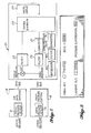
- FIG. 1 illustrates a system for measuring cabin pressure and ambient pressure and for using these measurements to display cabin altitude, cabin altitude rate, and a pressure differential between cabin pressure and static pressure.
- the cabin is pressurized to maintain a habitable environment for the passengers and crew.
- an aircraft flying at thirty five thousand feet will be pressurized to a cabin altitude of about eight thousand feet.
- the aircraft altitude may change several thousand feet per minute, however the cabin pressure is regulated so that it changes at a rate of only a few hundred feet per minute. To allow the pilot to monitor cabin altitude rate, it also is displayed.
- the exemplary system shown in FIG. 1 includes a sensor 10 which measures aircraft ambient (static) pressure.
- the sensor 10 which is part of a conventional air data computer 14, generates a digital static pressure output signal.
- cabin pressure is measured by a sensor 16.
- the sensor 16 is part of a cabin pressure controller 18 which generates a digital cabin pressure output signal.
- IDS integrated display system
- the IDS 20 portions of which are shown in FIG. 1, in an exemplary embodiment is the Integrated Display System aboard the Boeing 747-400 aircraft.
- the IDS 20 includes a main processor, a memory (both not shown), as well as a subtractor 21 which subtracts the static pressure signal from the cabin pressure signal to generate a pressure difference signal ( ⁇ P).
- the pressure difference signal is fed downstream to a unique filter 22 which will be described in greater detail hereinafter.
- the filtered signal is then fed to a conventional symbol generator 23 for displaying the cabin differential pressure at a conventional CRT display screen 24.
- the display is shown in greater detail in FIG. 2.
- the cabin pressure signal is also fed to a unique filter 26 which will be described in greater detail hereinafter.
- the filtered cabin pressure signal is converted to a cabin altitude signal at a converter 27.
- the filtered cabin altitude signal is then fed to the symbol generator 23 for displaying the cabin altitude at the display 24.
- the filtered cabin pressure signal is differentiated by a conventional differentiator 28 to generate a cabin pressure rate signal which is filtered by a unique downstream filter 30 which also is to be described in further detail hereinafter.
- the filtered cabin pressure rate signal is fed to a converter 31 for converting cabin pressure rate to cabin altitude rate.
- the cabin altitude rate signal is fed to the symbol generator 23 for displaying the cabin altitude rate at the display screen 24.
- those of the aforementioned components which are conventional are used aboard the Boeing 747-400 aircraft.
- the filters 22, 26, 30 are exponential infinite impulse response filters which are implemented in a conventional EFIS/EICAS interface unit (EIU) such as the EIU aboard the Boeing 747-400 aircraft.
- EIU EFIS/EICAS interface unit
- Each of these filters is a variable time constant filter.
- the time constants of the variable time constant filters are a direct function of the magnitude of the rate of change of the input signal S. That is, when there is a large step input or a rapidly changing signal, the time constants of the filters are shortened. On the other hand, if a small step input is present or there is a slowly changing signal, then the time constants of the filters are increased. In this manner the unwanted noise is removed from the signal while providing a smoothly changing output for driving the display.
- each filter has at least one variable time constant stage, and in a preferred embodiment each filter 22, 26, 30 has three cascaded variable time constant stages.
- PreF is a filtered output F from the immediately prior computation cycle of Equation 1
- ⁇ t is the computation cycle time
- T is the filter time constant.
- computation cycle time ( ⁇ t) is defined as the time between successive computations of the filtered value.
- the IDS 20 performs the filtering computations, stores these computations in memory, and then performs other tasks assigned to it before returning to compute another filtered value of the input signal S.
- the filter computation cycle time need not be the same as the computation cycle time of the main processor of the IDS 20. Where filter response requirements are slower than this, the filter computations may be divided into two or more segments so that the segments are computed in successive computation cycles of the main processor. In this manner the computation load per cycle of the main processor is reduced.
- the variable A is a direct function of the rate of change of the input signal; this rate of change being referred to hereinafter as DeltS.
- the value of K1 is selected to be greater than twice the computation cycle time; and preferably the value of K1 is selected to be three times the computation cycle time. This avoids the aliasing of signal fluctuations through the filters in accordance with Nyquist stability criterion.
- the value of the sum K1 + K2 is chosen to be greater than one-third the time interval between successive changes of the digital value of the input S at the minimum rate of change for which smooth response is required.
- cabin altitude rates are generally between one hundred and one thousand feet per minute; however some flight conditions may generate higher rates.
- the present values of K1 + K2 provide signal smoothing down to about forty feet per minute. At lower rates, the changes in input signal occur infrequently enough that the filtered rate value fluctuates. Since these lower rates occur as a transitory condition, the stability of the display is not affected.
- K1 + K2 assumes use of a three stage filter.
- the filtering effect of additional filter stages is approximately additive. Therefore, a fewer number of filter stages requires a larger value of K1 + K2, whereas a larger number of filter stages requires a smaller value of K1 + K2.
- the time constant may be adjusted to meet smoothness requirements of specific applications, e.g. longer time constant for increased smoothness of the filtered signal
- K5 a good initial value for K5 is six.
- system simulations and analysis may lead to other values as being optimum.
- the value of DeltS is determined by initially filtering the input S with a fixed time constant filter (Sfilt), and then determining the absolute value of the quantity (S - Sfilt).
- a baseline or reference is generated from which the time constant of the variable filter can be adjusted. For example, if the input signal is changing in a manner that the difference between the input signal S and the fixed time constant filtered value of S (Sfilt) is more than at least one significant bit of the digital input, then the time constant of the variable filters is shortened.
- PreSfilt is the value of Sfilt from the previous computation cycle
- K3 is a constant which is typically equal to the sum K1 + K2 and which can be adjusted to optimize filter response characteristics.
- the time constant of the fixed time constant filter is approximately equal to the maximum time constant of the variable time constant filter. This was found to be a good choice during simulations.
- a typical method for optimizing constants for use in the filters is to run simulations for various types of inputs, beginning with baseline or rule-of-thumb values and performing successive simulations with alternate values for the constants. The best performance is selected based on review of the results, and the corresponding constants used for a new baseline for another set of simulations, with this process repeated until all results are acceptable.
- an adaptive filter has been described for use with an cockpit display system. It should be appreciated the digital filter has applications to other systems such as robotics and flight controls where it is desirable to have the filter time constants at their maximum values for a slowly changing input signal, and at their minimum values for a rapidly changing input signal. The present filter accomplishes these functions while transitioning smoothly between these extremes.
- the filtered signal must have a greater number of data bits than that of the signal coming in. This allows the filtered signal to change in smaller increments than the incoming signal. For example, if the input signal has eight bit resolution and the processor also has eight bit resolution, operating the processor in double precision will provide signal processing at sixteen bit resolution. This will allow the filtered signal to change with eight more bits of resolution than the input signal, thereby providing much finer changes.
Landscapes
- Indication And Recording Devices For Special Purposes And Tariff Metering Devices (AREA)
- Control Of Indicators Other Than Cathode Ray Tubes (AREA)
- Traffic Control Systems (AREA)
- Filters That Use Time-Delay Elements (AREA)
Abstract
Description
- The present invention pertains to an adaptive digital filter having a time constant which is adjusted as a function of the rate of change of an input signal.
- Signals containing noise typically require filtering before they can be used to generate a visual display or to control a physical operation. Sometimes these signals are differentiated to obtain a rate signal. Differentiation typically causes the noise present in the original signal to be accentuated in the rate signal. For example, a noisy signal may generate visual displays which fluctuate excessively or control signals which do not result in a smoothly controlled operation. Even with a noise-free digital signal, step changes in the signal can result in large fluctuations in the rate signal. When the step changes in a digitally encoded signal are comparable in size or larger than the minimum step change of the display or of the motion control, and these changes are unfiltered, the response can be jerky or erratic.
- Some modern commercial aircraft utilize digital numerical displays of flight parameters such as cabin altitude and cabin altitude rate. If these signals are not properly filtered before driving a display, a small change in altitude may be displayed initially as a very large change. For example, an unfiltered noisy signal which represents a gradual change in cabin altitude of one hundred feet per minute may initially generate a displayed change in cabin altitude rate of several thousand feet per minute.
- These parameters may change slowly or rapidly depending upon the flight of the aircraft. When, for example, cabin altitude is changing at a slow rate, it is desirable to use a filter which has a longer time constant to average the signal over several steps of the input change, thereby achieving a smoothly changing response to the input. However, when cabin altitude is changing at a faster rate, it is desirable to use a filter which has a shorter time constant to permit faster response. When the input is changing faster, the digital step changes occur more frequently so several step changes can be averaged by a shorter time constant.
- A prior solution to this problem was to process the input signal using a filter having a fixed time constant. However, to generate a smoothly changing output in response to slowly changing signals, it was necessary to provide a time constant which was significantly longer than the time between changes in the step value. This prevented quick response to inputs having large step changes or inputs which had rapidly changing values.
- A number of conventional filters have been disclosed. For example, in U.S. Patent No. 4,654,811 by Jakubzick there is disclosed an adaptive digital filter having a time constant which is set to a high value when the incoming data changes at a slow rate, and which is set to a low value when the incoming data changes at a faster rate.
- The present invention pertains to a method for filtering a digital signal using at least one filter having a time constant which is variable. The time constant of the filter is a function of the rate of change of the signal entering the filter. Therefore, an object of the present invention is to regulate the filter time constant over a range so that it is at its maximum value during the smallest or slowest changes in the input signal, and so that it is at its minimum value during the largest or fastest changes in the input signal. Various selectable constants are provided to allow the filter characteristics to be optimized for various applications. Filtering the input signals for a period longer than the period between LSB changes can eliminate perturbations in these signals.
- The present invention will be discussed in greater detail in the following detailed description in conjunction with the attached drawings, in which:
- FIG. 1 is a block diagram of an exemplary system, which includes the digital filter of the present invention, for measuring and displaying cabin altitude, rate of change of cabin altitude, and a differential between cabin pressure and static pressure;
- FIG. 2 is a diagram of an exemplary cockpit display showing cabin altitude, cabin altitude rate, cabin pressure differential, and landing altitude;
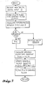
- FIG. 3 is a simplified flow chart describing an exemplary embodiment of the digital filter of the present invention;
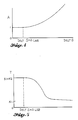
- FIG. 4 is a graph of variable "A" as a function of a variable DeltS; and
- FIG. 5 is a graph of variable time constant "T" as a function of DeltS.
- In an exemplary embodiment of the present invention reference is made to FIG. 1 which illustrates a system for measuring cabin pressure and ambient pressure and for using these measurements to display cabin altitude, cabin altitude rate, and a pressure differential between cabin pressure and static pressure. By way of background, in commercial jet aircraft the cabin is pressurized to maintain a habitable environment for the passengers and crew. Typically an aircraft flying at thirty five thousand feet will be pressurized to a cabin altitude of about eight thousand feet. It is desirable to display cabin altitude to allow the crew to monitor the cabin pressurization system. In a rapid descent, the aircraft altitude may change several thousand feet per minute, however the cabin pressure is regulated so that it changes at a rate of only a few hundred feet per minute. To allow the pilot to monitor cabin altitude rate, it also is displayed.
- The exemplary system shown in FIG. 1 includes a
sensor 10 which measures aircraft ambient (static) pressure. Thesensor 10, which is part of a conventional air data computer 14, generates a digital static pressure output signal. Inside the aircraft cabin, cabin pressure is measured by asensor 16. Thesensor 16 is part of a cabin pressure controller 18 which generates a digital cabin pressure output signal. These signals are transmitted to an integrated display system (IDS) indicated at 20. The IDS 20, portions of which are shown in FIG. 1, in an exemplary embodiment is the Integrated Display System aboard the Boeing 747-400 aircraft. The IDS 20 includes a main processor, a memory (both not shown), as well as a subtractor 21 which subtracts the static pressure signal from the cabin pressure signal to generate a pressure difference signal (ΔP). The pressure difference signal is fed downstream to aunique filter 22 which will be described in greater detail hereinafter. The filtered signal is then fed to aconventional symbol generator 23 for displaying the cabin differential pressure at a conventionalCRT display screen 24. The display is shown in greater detail in FIG. 2. - The cabin pressure signal is also fed to a
unique filter 26 which will be described in greater detail hereinafter. The filtered cabin pressure signal is converted to a cabin altitude signal at aconverter 27. The filtered cabin altitude signal is then fed to thesymbol generator 23 for displaying the cabin altitude at thedisplay 24. - In order to display the rate of change of cabin altitude (cabin altitude rate), the filtered cabin pressure signal is differentiated by a conventional differentiator 28 to generate a cabin pressure rate signal which is filtered by a unique downstream filter 30 which also is to be described in further detail hereinafter. The filtered cabin pressure rate signal is fed to a
converter 31 for converting cabin pressure rate to cabin altitude rate. The cabin altitude rate signal is fed to thesymbol generator 23 for displaying the cabin altitude rate at thedisplay screen 24. In a further exemplary embodiment, those of the aforementioned components which are conventional are used aboard the Boeing 747-400 aircraft. - In the present embodiment, the
filters - Each of these filters is a variable time constant filter. The time constants of the variable time constant filters are a direct function of the magnitude of the rate of change of the input signal S. That is, when there is a large step input or a rapidly changing signal, the time constants of the filters are shortened. On the other hand, if a small step input is present or there is a slowly changing signal, then the time constants of the filters are increased. In this manner the unwanted noise is removed from the signal while providing a smoothly changing output for driving the display.
- Implementation of the filters is described in further detail by referring to the flowchart in FIG. 3. However, for purposes of explanation, the description of the filtering operation will not follow the order of the flowchart. In the present exemplary embodiment, each filter has at least one variable time constant stage, and in a preferred embodiment each
filter
F = S + (1 - Δt/T) (PreF - S) (1),
where S is the input signal value, e.g. cabin pressure or ambient pressure from the sensors, PreF is a filtered output F from the immediately prior computation cycle ofEquation 1, Δt is the computation cycle time, and T is the filter time constant. The term "computation cycle time (Δt)" is defined as the time between successive computations of the filtered value. In the exemplary embodiment, theIDS 20 performs the filtering computations, stores these computations in memory, and then performs other tasks assigned to it before returning to compute another filtered value of the input signal S. The filter computation cycle time need not be the same as the computation cycle time of the main processor of theIDS 20. Where filter response requirements are slower than this, the filter computations may be divided into two or more segments so that the segments are computed in successive computation cycles of the main processor. In this manner the computation load per cycle of the main processor is reduced. - The filter time constant T is expressed by the equation
T = K1 + K2/A (seconds) (2),
where K1 is a selected minimum value of the time constant, the sum K1 + K2 is a selected maximum value of the time constant, and A is value which adjusts the time constant in a range between its minimum and maximum values. The variable A is a direct function of the rate of change of the input signal; this rate of change being referred to hereinafter as DeltS. - In the exemplary embodiment where a three stage variable time constant filter is used, the value of K1 is selected to be greater than twice the computation cycle time; and preferably the value of K1 is selected to be three times the computation cycle time. This avoids the aliasing of signal fluctuations through the filters in accordance with Nyquist stability criterion.
- In this exemplary embodiment, the value of the sum K1 + K2 is chosen to be greater than one-third the time interval between successive changes of the digital value of the input S at the minimum rate of change for which smooth response is required. In the present embodiment, cabin altitude rates are generally between one hundred and one thousand feet per minute; however some flight conditions may generate higher rates. The present values of K1 + K2 provide signal smoothing down to about forty feet per minute. At lower rates, the changes in input signal occur infrequently enough that the filtered rate value fluctuates. Since these lower rates occur as a transitory condition, the stability of the display is not affected.
- The aforementioned exemplary value of K1 + K2 assumes use of a three stage filter. For input changes occurring during a period which is similar to the filter's time constant, the filtering effect of additional filter stages is approximately additive. Therefore, a fewer number of filter stages requires a larger value of K1 + K2, whereas a larger number of filter stages requires a smaller value of K1 + K2. In addition, the time constant may be adjusted to meet smoothness requirements of specific applications, e.g. longer time constant for increased smoothness of the filtered signal
- If DeltS is less than the rate of change of one least significant bit change (ΔLSB) of the digital value of the input signal, then the variable A = 1. In other words, if the input signal S has its increments of change (changes of one LSB) occurring at intervals greater than the time constant of the fixed filter, the maximum time constant (K1 + K2) is used in the variable filter.
- Otherwise, if DeltS is greater than or equal to ΔLSB, then the value of A is determined by the equation
A = 1 + [(DeltS - K4)/(K4 * K5)]² (3),
where K4 = ΔLSB and K5 is a constant having a value which is selected to optimize filter response. This is reflected by a graph illustrated in FIG. 5 where time constant T is a function of DeltS. When DeltS is less than ΔLSB, then the variable time constant does not change. However when DeltS is greater than ΔLSB, it is desirable to generate time constant values which are adjusted downward in smaller increments for lower values of DeltS, and which are adjusted downward in larger increments for larger values of DeltS. Therefore, at DeltS values greater than ΔLSB, equation #3 describes a parabolic curve which satisfies the above mentioned criteria. Furthermore, at the "change point" where DeltS = ΔLSB, the straight line segment and the curved segments join so that there is a smooth transition therebetween. This provides for smooth and continuous operation of the filter. In this manner, T will eventually approach, but never reach, the value of K1 (the minimum filter constant value). - It has been found that a good initial value for K5 is six. For applications other than visual displays, system simulations and analysis may lead to other values as being optimum.
- In an alternate embodiment the variable A is calculated in a different manner. That is, when DeltS is less than the sum of K4 + K5, then A = 1. Otherwise, when DeltS is greater than or equal to the sum of K4 + K5, then
A = (DeltS - K4)/K5 (4),
where K4 = ΔLSB and K5 is a selectable constant which may be initialized at one-fourth the value of K4. This embodiment provides a simpler method of calculating the value A and is preferable when signal processing must be done at high speed or when minimal computation capability is available. - In the present invention, the value of DeltS is determined by initially filtering the input S with a fixed time constant filter (Sfilt), and then determining the absolute value of the quantity (S - Sfilt). By filtering the input with a filter having a known fixed time constant, a baseline or reference is generated from which the time constant of the variable filter can be adjusted. For example, if the input signal is changing in a manner that the difference between the input signal S and the fixed time constant filtered value of S (Sfilt) is more than at least one significant bit of the digital input, then the time constant of the variable filters is shortened.
- The fixed time constant filter has the transfer function
Sfilt = S + e⁻ Δt/K3 (PreSfilt - S) (5),
where PreSfilt is the value of Sfilt from the previous computation cycle, and K3 is a constant which is typically equal to the sum K1 + K2 and which can be adjusted to optimize filter response characteristics. In this manner, the time constant of the fixed time constant filter is approximately equal to the maximum time constant of the variable time constant filter. This was found to be a good choice during simulations. - A typical method for optimizing constants for use in the filters is to run simulations for various types of inputs, beginning with baseline or rule-of-thumb values and performing successive simulations with alternate values for the constants. The best performance is selected based on review of the results, and the corresponding constants used for a new baseline for another set of simulations, with this process repeated until all results are acceptable.
- In the aforementioned exemplary embodiment, an adaptive filter has been described for use with an cockpit display system. It should be appreciated the the digital filter has applications to other systems such as robotics and flight controls where it is desirable to have the filter time constants at their maximum values for a slowly changing input signal, and at their minimum values for a rapidly changing input signal. The present filter accomplishes these functions while transitioning smoothly between these extremes.
- It should be noted that for the filter to be effective, the filtered signal must have a greater number of data bits than that of the signal coming in. This allows the filtered signal to change in smaller increments than the incoming signal. For example, if the input signal has eight bit resolution and the processor also has eight bit resolution, operating the processor in double precision will provide signal processing at sixteen bit resolution. This will allow the filtered signal to change with eight more bits of resolution than the input signal, thereby providing much finer changes.
Claims (1)
Applications Claiming Priority (2)
| Application Number | Priority Date | Filing Date | Title |
|---|---|---|---|
| US07/295,858 US5150317A (en) | 1989-01-11 | 1989-01-11 | Adaptive digital filter which is responsive to the rate of change of an input signal |
| US295858 | 1989-01-11 |
Publications (3)
| Publication Number | Publication Date |
|---|---|
| EP0377913A2 true EP0377913A2 (en) | 1990-07-18 |
| EP0377913A3 EP0377913A3 (en) | 1990-12-12 |
| EP0377913B1 EP0377913B1 (en) | 1996-01-10 |
Family
ID=23139516
Family Applications (1)
| Application Number | Title | Priority Date | Filing Date |
|---|---|---|---|
| EP89201512A Expired - Lifetime EP0377913B1 (en) | 1989-01-11 | 1989-06-09 | Adaptive digital filter which is responsive to the rate of change of an input signal |
Country Status (3)
| Country | Link |
|---|---|
| US (1) | US5150317A (en) |
| EP (1) | EP0377913B1 (en) |
| DE (1) | DE68925415T2 (en) |
Cited By (7)
| Publication number | Priority date | Publication date | Assignee | Title |
|---|---|---|---|---|
| EP0572242A3 (en) * | 1992-05-27 | 1994-02-16 | Foxboro Co | |
| EP0701186A3 (en) * | 1994-08-15 | 1996-07-03 | Praxair Technology Inc | Model predictive control method for an air-separation system |
| US5537388A (en) * | 1994-03-02 | 1996-07-16 | The Foxboro Company | Method and apparatus for characterizing and compensating for non-linear components |
| GB2389284A (en) * | 2002-05-31 | 2003-12-03 | Matsushita Electric Industrial Co Ltd | The bandwidth of an adaptive filter is controlled by a proportional and derivative (PD) controller |
| US8027810B2 (en) | 2004-01-26 | 2011-09-27 | British Telecommunications Public Limited Company | Ad hoc sensor networks |
| EP3690592A1 (en) | 2019-01-30 | 2020-08-05 | Siemens Schweiz AG | Control valve |
| CN111868716A (en) * | 2018-01-04 | 2020-10-30 | 赛峰飞机发动机公司 | adaptive filtering method |
Families Citing this family (16)
| Publication number | Priority date | Publication date | Assignee | Title |
|---|---|---|---|---|
| DE4109211A1 (en) * | 1991-03-21 | 1992-09-24 | Philips Patentverwaltung | CIRCUIT ARRANGEMENT FOR INFLUENCING THE DIGITAL AUDIO SIGNAL |
| JP3233450B2 (en) * | 1992-05-22 | 2001-11-26 | 本田技研工業株式会社 | Specified time arrival function generator |
| US5764552A (en) * | 1993-02-18 | 1998-06-09 | The Dow Chemical Company | Method for adjusting an adaptive exponential filter |
| ATE167765T1 (en) * | 1993-02-18 | 1998-07-15 | Dow Deutschland Inc | METHOD OF ADJUSTING AN ADAPTIVE EXPONENTIAL FILTER AND ADAPTIVE EXPONENTIAL FILTER |
| US5381355A (en) * | 1993-12-17 | 1995-01-10 | Elsag International N.V. | Method for filtering digital signals in a pressure transmitter |
| US5532950A (en) * | 1994-04-25 | 1996-07-02 | Wadia Digital Corporation | Dynamic digital filter using neural networks |
| US5812429A (en) * | 1994-06-23 | 1998-09-22 | Delco Electronics Corp. | Adaptive digital filter for automotive applications |
| US5838599A (en) * | 1996-09-13 | 1998-11-17 | Measurex Corporation | Method and apparatus for nonlinear exponential filtering of signals |
| US20030165212A1 (en) * | 1998-02-18 | 2003-09-04 | Maglich Bogdan C. | Method and apparatus for detecting, locating, and analyzing chemical compounds using subatomic particle activation |
| US5995989A (en) * | 1998-04-24 | 1999-11-30 | Eg&G Instruments, Inc. | Method and apparatus for compression and filtering of data associated with spectrometry |
| US7078872B2 (en) * | 2003-05-30 | 2006-07-18 | Caterpillar Inc | System and method for conditioning a signal |
| US7101277B2 (en) * | 2003-07-22 | 2006-09-05 | Honeywell International, Inc. | Control system and method for controlling aircraft cabin altitude during aircraft operations above maximum certified aircraft altitude |
| WO2005088245A1 (en) * | 2004-03-11 | 2005-09-22 | Hienergy Technologies, Inc. | Method and apparatus for measuring wall thickness of a vessel |
| US20090201287A1 (en) * | 2008-02-07 | 2009-08-13 | Honeywell International Inc. | System and method of adaptively filtering parametric data for display |
| US9654106B1 (en) | 2015-12-21 | 2017-05-16 | Schneider Electric USA, Inc. | Dynamic digital input filtering |
| US12347298B2 (en) * | 2019-12-23 | 2025-07-01 | Vayyar Imaging Ltd. | Target monitoring and alert system and method |
Family Cites Families (12)
| Publication number | Priority date | Publication date | Assignee | Title |
|---|---|---|---|---|
| US3177349A (en) * | 1960-10-31 | 1965-04-06 | Mcdonnell Aircraft Corp | Filter network |
| US3778602A (en) * | 1970-10-30 | 1973-12-11 | King Radio Corp | Area navigation computer and solid state filter |
| FR2118410A5 (en) * | 1970-12-17 | 1972-07-28 | Ibm France | |
| US3908115A (en) * | 1974-10-07 | 1975-09-23 | Weston Instruments Inc | Adaptively tuned data receiver |
| FR2336005A1 (en) * | 1975-12-18 | 1977-07-15 | Ibm France | SELF-ADAPTIVE DIGITAL FILTER |
| US4066878A (en) * | 1976-03-29 | 1978-01-03 | Miller Raymond M | Time-domain filter for recursive type signals |
| FR2343223A1 (en) * | 1976-07-01 | 1977-09-30 | Trt Telecom Radio Electr | FILTERING OF ALARMS IN A SOIL PROXIMITY MONITORING SYSTEM |
| US4590579A (en) * | 1983-10-04 | 1986-05-20 | Ramsey Engineering Company | Apparatus and method for digital specific gravity measurement |
| US4674062A (en) * | 1984-04-20 | 1987-06-16 | General Electric Company | Apparatus and method to increase dynamic range of digital measurements |
| US4654811A (en) * | 1985-02-12 | 1987-03-31 | Allied Corporation | Adaptive filter for aircraft navigation receiver |
| JPS61269710A (en) * | 1985-05-24 | 1986-11-29 | Mitsubishi Heavy Ind Ltd | Digitizing method for profile track |
| DE3620614A1 (en) * | 1986-06-20 | 1987-12-23 | Gutehoffnungshuette Man | METHOD FOR FILTERING A NOISY SIGNAL |
-
1989
- 1989-01-11 US US07/295,858 patent/US5150317A/en not_active Expired - Fee Related
- 1989-06-09 DE DE68925415T patent/DE68925415T2/en not_active Expired - Fee Related
- 1989-06-09 EP EP89201512A patent/EP0377913B1/en not_active Expired - Lifetime
Cited By (9)
| Publication number | Priority date | Publication date | Assignee | Title |
|---|---|---|---|---|
| EP0572242A3 (en) * | 1992-05-27 | 1994-02-16 | Foxboro Co | |
| US5335165A (en) * | 1992-05-27 | 1994-08-02 | The Foxboro Company | Method and apparatus for adaptive deadtime process control |
| US5537388A (en) * | 1994-03-02 | 1996-07-16 | The Foxboro Company | Method and apparatus for characterizing and compensating for non-linear components |
| EP0701186A3 (en) * | 1994-08-15 | 1996-07-03 | Praxair Technology Inc | Model predictive control method for an air-separation system |
| GB2389284A (en) * | 2002-05-31 | 2003-12-03 | Matsushita Electric Industrial Co Ltd | The bandwidth of an adaptive filter is controlled by a proportional and derivative (PD) controller |
| GB2389284B (en) * | 2002-05-31 | 2004-07-14 | Matsushita Electric Industrial Co Ltd | Bandwidth adaptation rule for adaptive noise filter for inverse filtering with improved speed |
| US8027810B2 (en) | 2004-01-26 | 2011-09-27 | British Telecommunications Public Limited Company | Ad hoc sensor networks |
| CN111868716A (en) * | 2018-01-04 | 2020-10-30 | 赛峰飞机发动机公司 | adaptive filtering method |
| EP3690592A1 (en) | 2019-01-30 | 2020-08-05 | Siemens Schweiz AG | Control valve |
Also Published As
| Publication number | Publication date |
|---|---|
| DE68925415T2 (en) | 1996-05-23 |
| DE68925415D1 (en) | 1996-02-22 |
| EP0377913B1 (en) | 1996-01-10 |
| EP0377913A3 (en) | 1990-12-12 |
| US5150317A (en) | 1992-09-22 |
Similar Documents
| Publication | Publication Date | Title |
|---|---|---|
| US5150317A (en) | Adaptive digital filter which is responsive to the rate of change of an input signal | |
| EP0031619B1 (en) | Vertical flight path steering system for aircraft | |
| US6158695A (en) | Method of speed protection and flare compensation for use with aircraft pitch control system | |
| US4044975A (en) | Aircraft speed command system | |
| US4277041A (en) | Aircraft cruise speed control system | |
| EP0743582A2 (en) | Method and apparatus for the linear real time estimation of an aircraft center of gravity | |
| US3652835A (en) | Aircraft glide slope coupler system | |
| EP0743244A1 (en) | Autopilot/flight director overspeed protection system | |
| EP0743584A1 (en) | Aircraft vertical position control system | |
| US4422147A (en) | Wind shear responsive turbulence compensated aircraft throttle control system | |
| US5070287A (en) | Method for a numerical positioning control system | |
| US5497063A (en) | Fuzzy logic servo controller | |
| US5860625A (en) | Aircraft frequency adaptive modal suppression system | |
| US4413320A (en) | Control system | |
| JPS58218498A (en) | Altitude previous selective system for aircraft requiring no atmosphere data calculator | |
| JPH0567478B2 (en) | ||
| EP0742141A1 (en) | Method and apparatus for providing a dynamic thrust asymmetry rudder compensation command with no direct thrust measurement | |
| EP0471395A2 (en) | Apparatus and methods for controlling commanded operation of an aircraft within a predetermined flight parameter limit | |
| EP0444541B1 (en) | Apparatus and method for a smooth transition between calibrated airspeed control of an aircraft and mach number control of an aircraft | |
| US5397973A (en) | Gain control for fuzzy logic controller | |
| US5117362A (en) | Path capture forcing function generator for aircraft vertical axis control | |
| US5089968A (en) | Ground effects compensated real time aircraft body angle of attack estimation | |
| US5689251A (en) | Airspeed prediction filter | |
| US3280310A (en) | Aircraft landing system | |
| US3724786A (en) | Aircraft ground speed control system |
Legal Events
| Date | Code | Title | Description |
|---|---|---|---|
| PUAI | Public reference made under article 153(3) epc to a published international application that has entered the european phase |
Free format text: ORIGINAL CODE: 0009012 |
|
| AK | Designated contracting states |
Kind code of ref document: A2 Designated state(s): DE FR GB IT NL |
|
| PUAL | Search report despatched |
Free format text: ORIGINAL CODE: 0009013 |
|
| AK | Designated contracting states |
Kind code of ref document: A3 Designated state(s): DE FR GB IT NL |
|
| 17P | Request for examination filed |
Effective date: 19910612 |
|
| 17Q | First examination report despatched |
Effective date: 19930920 |
|
| GRAA | (expected) grant |
Free format text: ORIGINAL CODE: 0009210 |
|
| AK | Designated contracting states |
Kind code of ref document: B1 Designated state(s): DE FR GB IT NL |
|
| PG25 | Lapsed in a contracting state [announced via postgrant information from national office to epo] |
Ref country code: IT Free format text: LAPSE BECAUSE OF FAILURE TO SUBMIT A TRANSLATION OF THE DESCRIPTION OR TO PAY THE FEE WITHIN THE PRESCRIBED TIME-LIMIT;WARNING: LAPSES OF ITALIAN PATENTS WITH EFFECTIVE DATE BEFORE 2007 MAY HAVE OCCURRED AT ANY TIME BEFORE 2007. THE CORRECT EFFECTIVE DATE MAY BE DIFFERENT FROM THE ONE RECORDED. Effective date: 19960110 Ref country code: NL Free format text: LAPSE BECAUSE OF FAILURE TO SUBMIT A TRANSLATION OF THE DESCRIPTION OR TO PAY THE FEE WITHIN THE PRESCRIBED TIME-LIMIT Effective date: 19960110 |
|
| REF | Corresponds to: |
Ref document number: 68925415 Country of ref document: DE Date of ref document: 19960222 |
|
| ET | Fr: translation filed | ||
| NLV1 | Nl: lapsed or annulled due to failure to fulfill the requirements of art. 29p and 29m of the patents act | ||
| PGFP | Annual fee paid to national office [announced via postgrant information from national office to epo] |
Ref country code: GB Payment date: 19960610 Year of fee payment: 8 |
|
| PGFP | Annual fee paid to national office [announced via postgrant information from national office to epo] |
Ref country code: FR Payment date: 19960627 Year of fee payment: 8 |
|
| PGFP | Annual fee paid to national office [announced via postgrant information from national office to epo] |
Ref country code: DE Payment date: 19960731 Year of fee payment: 8 |
|
| PLBE | No opposition filed within time limit |
Free format text: ORIGINAL CODE: 0009261 |
|
| STAA | Information on the status of an ep patent application or granted ep patent |
Free format text: STATUS: NO OPPOSITION FILED WITHIN TIME LIMIT |
|
| 26N | No opposition filed | ||
| PG25 | Lapsed in a contracting state [announced via postgrant information from national office to epo] |
Ref country code: GB Free format text: LAPSE BECAUSE OF NON-PAYMENT OF DUE FEES Effective date: 19970609 |
|
| GBPC | Gb: european patent ceased through non-payment of renewal fee |
Effective date: 19970609 |
|
| PG25 | Lapsed in a contracting state [announced via postgrant information from national office to epo] |
Ref country code: FR Free format text: LAPSE BECAUSE OF NON-PAYMENT OF DUE FEES Effective date: 19980227 |
|
| PG25 | Lapsed in a contracting state [announced via postgrant information from national office to epo] |
Ref country code: DE Free format text: LAPSE BECAUSE OF NON-PAYMENT OF DUE FEES Effective date: 19980303 |
|
| REG | Reference to a national code |
Ref country code: FR Ref legal event code: ST |
|
| REG | Reference to a national code |
Ref country code: FR Ref legal event code: ST |