EP3690577B1 - Management system and management method for cutting machine - Google Patents
Management system and management method for cutting machine Download PDFInfo
- Publication number
- EP3690577B1 EP3690577B1 EP20154117.4A EP20154117A EP3690577B1 EP 3690577 B1 EP3690577 B1 EP 3690577B1 EP 20154117 A EP20154117 A EP 20154117A EP 3690577 B1 EP3690577 B1 EP 3690577B1
- Authority
- EP
- European Patent Office
- Prior art keywords
- cutting machine
- instruction
- server device
- identifier
- cutting
- Prior art date
- Legal status (The legal status is an assumption and is not a legal conclusion. Google has not performed a legal analysis and makes no representation as to the accuracy of the status listed.)
- Active
Links
Images





Classifications
-
- G—PHYSICS
- G05—CONTROLLING; REGULATING
- G05B—CONTROL OR REGULATING SYSTEMS IN GENERAL; FUNCTIONAL ELEMENTS OF SUCH SYSTEMS; MONITORING OR TESTING ARRANGEMENTS FOR SUCH SYSTEMS OR ELEMENTS
- G05B19/00—Program-control systems
- G05B19/02—Program-control systems electric
- G05B19/418—Total factory control, i.e. centrally controlling a plurality of machines, e.g. direct or distributed numerical control [DNC], flexible manufacturing systems [FMS], integrated manufacturing systems [IMS] or computer integrated manufacturing [CIM]
- G05B19/4185—Total factory control, i.e. centrally controlling a plurality of machines, e.g. direct or distributed numerical control [DNC], flexible manufacturing systems [FMS], integrated manufacturing systems [IMS] or computer integrated manufacturing [CIM] characterised by the network communication
-
- Y—GENERAL TAGGING OF NEW TECHNOLOGICAL DEVELOPMENTS; GENERAL TAGGING OF CROSS-SECTIONAL TECHNOLOGIES SPANNING OVER SEVERAL SECTIONS OF THE IPC; TECHNICAL SUBJECTS COVERED BY FORMER USPC CROSS-REFERENCE ART COLLECTIONS [XRACs] AND DIGESTS
- Y02—TECHNOLOGIES OR APPLICATIONS FOR MITIGATION OR ADAPTATION AGAINST CLIMATE CHANGE
- Y02P—CLIMATE CHANGE MITIGATION TECHNOLOGIES IN THE PRODUCTION OR PROCESSING OF GOODS
- Y02P90/00—Enabling technologies with a potential contribution to greenhouse gas [GHG] emissions mitigation
- Y02P90/02—Total factory control, e.g. smart factories, flexible manufacturing systems [FMS] or integrated manufacturing systems [IMS]
Definitions
- the present teaching relates to a management system and to a management method for a cutting machine.
- JP2017-94436A discloses a cutting machine including a retainer for retaining a workpiece, a spindle for rotating a processing tool, and a mechanism for moving the retainer and the spindle in parallel in three dimensions.
- IoT Internet of Things
- the master node may be connected to a plurality of slave nodes representing non-welding or cutting peripherals like user interface panels, wire feeders, power sources etc.
- a distributed system of a plurality of welding or cutting systems one device being the client device and the other the master device.
- EP3416004A1 describes a control of field devices installed in a factory by a central management apparatus.
- the central management apparatus includes a management application (FDT) and device controllers (DTM).
- the DTMs respectively manage the field devices in the factory while the FDT manages the DTMs and provides the user with an interface for enabling them to operate the DTMs.
- the FTM includes a device identifier acquirer which acquires form each of the DTMs a device identifier which identify the filed devices. Based on the acquired device identifier a device management screen is generated and displayed for providing data obtained from the respective filed device to the user.
- the present teaching has been made in in view of the foregoing situations, and has an object of providing a management system and method for a cutting machine capable of managing even a cutting machine having no network connecting function by using a network.
- each cutting machine connected to the intermediary device is identified by the identifier generated by the intermediary device, and thus, the interposition of the intermediary device provides similar advantages as including an address on the network.
- an instruction specifying an identifier even an instruction issued to the server device from an operation terminal connected to the network can be transmitted to a specified cutting machine through the server device and the intermediary device connected to the server device through the network.
- the system described above can manage even cutting machines having no network connecting function by using a network.
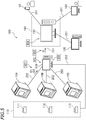
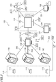
- FIG. 1 schematically illustrates a management system 100 for a cutting machine according to one preferred embodiment (hereinafter referred to as a management system 100).
- the management system 100 includes a server device 150, an intermediary computer 120, and a shooting system 110.
- the intermediary computer 120 is connected to a server device 150 through the Internet 201.
- a plurality of cutting machines 10A, 10B, and 10C are connected to the intermediary computer 120.
- the tree cutting machines 10A through 10C are directly connected to the intermediary computer 120 by USB cables 202.
- One or four or more cutting machines may be connected to the intermediary computer 120.
- the shooting system 110 is also directly connected to the intermediary computer 120.
- a plurality of intermediary computers 120 may be connected to the server device 150.
- One or more cutting machines are connected to each intermediary computer 120.
- Some intermediary computers 120 may not be connected to the shooting system 110.
- the server device 150 in this preferred embodiment is a server in a cloud computing system 140, and is connected to the Internet 201.
- the server device 150 is configured to be connectable to a plurality of operation terminals 160 through the Internet.
- FIG. 1 illustrates an example state in which the plurality of operation terminals 160 are connected to the server device 150, the operation terminals 160 do not need to be always connected to the server device 150.
- the operation terminals 160 only need to be connected to necessary components when necessary.
- the operation terminals 160 are, for example, computers and/or smartphones.
- the server device 150 and the operation terminals 160 are connected to each other through the Internet 201.
- the Internet 201 may be constituted by wires or wirelessly.
- FIG. 2 is a perspective view illustrating an example of a first cutting machine 10A.
- FIG. 2 illustrates the first cutting machine 10A in a state where a door 25 is open.
- left, right, upward, and downward will be referred to as left, right, upward, and downward, respectively, when seen from a user at the door 25 of the first cutting machine 10A.
- a direction toward the first cutting machine 10A from the user will be referred to as rear, and a direction away from the first cutting machine 10A will be referred to as front.
- Characters F, Rr, L, R, U, and D in the drawings represent front, rear, left, right, upward, and downward, respectively.
- the first cutting machine 10A has a box shape.
- the first cutting machine 10A includes a chassis 20 and the door 25.
- the chassis 20 has a box shape having an opening at the front.
- the opening at the front of the chassis 20 is provided with the door 25.
- the door 25 can be opened and closed.
- the door 25 is vertically slidably attached to the chassis 20. The vertical sliding of the door 25 enables the inside and the outside of the chassis 20 to communicate with each other through the opening at the front of the chassis 20.
- FIG. 3 is a vertical cross-sectional view of the first cutting machine 10A.
- a floor surface 20a1 of a processing space 20a on which a cutting workpiece W is processed inside the chassis 20 is declined rearward.
- a main shaft 30 for rotating a tool T is tilted to be perpendicular to the floor surface 20a1 of the processing space 20a.
- the front-rear direction of the floor surface 20a1 of the processing space 20a will be referred to as a direction X1, and a direction in which the main shaft 30 extends will be referred to as a direction Z1.
- the left-right direction of the first cutting machine 10A will be referred to as a direction Y.
- the main shaft 30, a retaining mechanism 40, an Xl-moving mechanism 51, a Y-moving mechanism 52 (see FIG. 4A and 4B ), and a Zl-moving mechanism 53 are disposed.
- the main shaft 30 holds the tool T and rotates the tool T.
- the main shaft 30 includes a driver 31 and a holder 32.
- the holder 32 holds the tool T at the tip of the main shaft 30.
- the driver 31 rotates the tool T held by the holder 32, together with the holder 32.
- the retaining mechanism 40 is configured to retain the cutting workpiece W.
- the cutting workpiece W is, for example, a material for artificial teeth.
- the retaining mechanism 40 retains the cutting workpiece W, and rotates the cutting workpiece W in directions A1 and A2 in FIG. 3 . This rotation can change the posture of the cutting workpiece W relative to the tool T variously.
- the main shaft 30 is moved in directions Y and Z1 by the Y-moving mechanism 52 and the Zl-moving mechanism 53.
- the tool T retained by the main shaft 30 moves in the directions Y and Z1 together with the main shaft 30.
- the retaining mechanism 40 is moved in the direction X1 by the Xl-moving mechanism 51.
- the cutting workpiece W retained by the retaining mechanism 40 moves in the direction X1 together with the retaining mechanism 40. Accordingly, a positional relationship between the tool T and the cutting workpiece W in three dimensions can be changed from moment to moment.
- the first cutting machine 10A includes a controller 60.
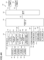
- FIG. 4A and 4B are block diagrams of the management system 100 according to this preferred embodiment. As illustrated in FIG. 4A and 4B , the controller 60 is connected to the main shaft 30, the retaining mechanism 40, the Xl-moving mechanism 51, the Y-moving mechanism 52, and the Zl-moving mechanism 53.
- the controller 60 is not limited to a specific configuration.
- the controller 60 is, for example, a microcomputer.
- the microcomputer is not limited to specific hardware configuration, but includes, for example, an interface (I/F) for receiving cutting data or other data from external equipment such as a host computer, a central processing unit (CPU) for executing an instruction of a control program, a read only memory (ROM) storing a program to be executed by the CPU, a random access memory (RAM) used as a working area where a program is to be developed, and a storage device, such as a memory, for storing the programs and the various types of data described above. All the functions of components of the controller 60 do not need to be implemented by hardware disposed inside the chassis 20, and a computer or another component connected to the controller 60 may implement some of the functions.
- I/F interface
- CPU central processing unit
- ROM read only memory
- RAM random access memory
- the controller 60 includes a cutting controller 61, an instruction receiver 62, a status information transmitter 63, and a machine information memory 64.
- the controller 60 may include other processors, but description thereof will be omitted.
- the cutting controller 61 controls the main shaft 30, the retaining mechanism 40, the Xl-moving mechanism 51, the Y-moving mechanism 52, and the Zl-moving mechanism 53 to perform a cutting process on the cutting workpiece W.
- the instruction receiver 62 is configured to receive an instruction from external equipment and cause the cutting controller 61, for example, to execute the instruction.
- the first cutting machine 10A is connected to the intermediary computer 120, and the instruction receiver 62 receives instructions from the intermediary computer 120. Examples of the instructions from the intermediary computer 120 include instructions for starting, suspending, skipping, and stopping a cutting process, an instruction for sending status information, and an instruction for transmitting machine information.
- the status information transmitter 63 transmits status information of the first cutting machine 10A.
- the status information transmitter 63 transmits status information to the intermediary computer 120.
- the status information includes, for example, information concerning a progress of a cutting process and error information.
- the machine information memory 64 stores information concerning the first cutting machine 10A itself.
- the machine information memory 64 includes a model information memory 64a and a product number information memory 64b, and stores model information and product number information.
- the model information memory 64a stores model information of the first cutting machine 10A.
- the model information is constituted by characters representing a type of the first cutting machine 10A, for example.
- the product number information memory 64b stores product number information of the first cutting machine 10A.
- the product number information is, for example, a serial number of the first cutting machine 10A.
- the first cutting machine 10A in this preferred embodiment is a cutting machine that does not have the function of enabling internet connection.
- the management system 100 for the cutting machines according to this preferred embodiment also enables an operation of a cutting machine not having the function of Internet connection, such as the first cutting machine 10A, through the Internet. It should be noted that the first cutting machine 10A may have the internet connection function.
- the second cutting machine 10B and the third cutting machine 10C may have cutting machines of the same model as the first cutting machine 10A, or may be cutting machines of models different from the first cutting machine 10A.
- the second cutting machine 10B and the third cutting machine 10C also need to store model information and product number information, and the intermediary computer 120 needs to be capable of reading the model information and the product number information.
- the configuration of the first cutting machine 10A described above is merely an example, and is not intended to limit the type of the cutting machines.
- the shooting system 110 is configured to enable shooting of images of the cutting machines 10A through 10C.
- the shooting system 110 in this preferred embodiment is directly connected to the intermediary computer 120 by the USB cable 202.
- the shooting system 110 captures images of the cutting machines 10A through 10C based on an instruction of the intermediary computer 120.
- the shooting system 110 includes a first camera 111, a second camera 112, and a third camera 113.
- the first camera 111 is disposed to capture an image of the first cutting machine 10A.
- the first camera 111 is configured to capture a moving image in the processing space 20a of the first cutting machine 10A, for example.
- Objects to be captured by the first camera 111 are not limited to the example above.
- the first camera 111 may capture an appearance of the first cutting machine 10A.
- the second camera 112 captures an image of the second cutting machine 10B based on an instruction of the intermediary computer 120.
- the third camera 113 captures an image of the third cutting machine 10C based on an instruction of the intermediary computer 120.
- one camera does not need to be provided to one cutting machine.
- the shooting system 110 may include cameras in a number smaller than the number of cutting machines, and may capture an image of a specified cutting machine by moving or rotating the cameras. The cameras may be incorporated in the cutting machines.
- the intermediary computer 120 is a computer to which the plurality of cutting machines 10A through 10C are directly connected, and performs transfer between the server device 150 and each of the plurality of cutting machines 10A through 10C.
- the intermediary computer 120 in this preferred embodiment is a general computer on which software for implementing functions is mounted.
- An intermediary device exemplified by the intermediary computer 120 of the preferred embodiment may not be a general computer, and may be dedicated hardware.
- the intermediary computer 120 includes an identifier generator 121, an identifier transmitter 122, a client generator 123, an instruction receiver 124, an instruction transmitter 125, a status information receiver 126, a status information transmitter 127, a shooting instruction receiver 128, a shooting instruction transmitter 129, a video receiver 130, and a video transmitter 131.
- the identifier generator 121 acquires machine information from each cutting machine connected to the intermediary computer 120, and based on the acquired machine information, generates an identification ID of the connected cutting machine. In the example configuration of FIG. 1 , the identifier generator 121 generates an identification ID of the first cutting machine 10A, an identification ID of the second cutting machine 10B, and an identification ID of the third cutting machine 10C.
- the identifier generator 121 generates identification IDs based on the machine information of the cutting machines.
- the identifier generator 121 includes an acquirer 121a and a generator 121b.
- the acquirer 121a acquires model information and product number information from each of the cutting machines 10A through 10C.
- the generator 121b generates identification IDs of the cutting machines 10A through 10C based on the model information and the product number information acquired by the acquirer 121a.
- the generator 121b generates, for example, characters serially representing a type and a serial number of a connected cutting machine, as an identification ID of this cutting machine. Such identification IDs can uniquely identify all the cutting machines.
- the method for generating identification IDs described above is an example, and is not intended to limit the present teaching.
- the identifier transmitter 122 transmits the identification IDs generated by the identifier generator 121 to the server device 150. Although specifically described later, the identification IDs generated by the identifier generator 121 are recorded in the server device 150. Thus, even when the cutting machine is not present any more, the identification IDs remain and are stored in the server device 150.
- the client generator 123 recognizes the connected cutting machines, and generates a client to communicate with the server device 150 for each connected cutting machine.
- the client in this preferred embodiment is an imaginary intermediator that is linked to each of the identification IDs of the cutting machines 10A through 10C and used for transmission between the server device 150 and the cutting machines 10A through 10C.
- an instruction specifying the identification ID of one cutting machine is issued from the operation terminal 160 through the server device 150, only the client of the cutting machine corresponding to this specification processes this instruction. Accordingly, the intermediary computer 120 performs transfer between the cutting machines 10A through 10C and the server device 150.
- the instruction receiver 124, the instruction transmitter 125, the status information receiver 126, the status information transmitter 127, the shooting instruction receiver 128, the shooting instruction transmitter 129, the video receiver 130, and the video transmitter 131 are provided in the client of each of the plurality of cutting machines 10A through 10C, and processes an instruction and information.
- Each client includes the instruction receiver 124, the instruction transmitter 125, the status information receiver 126, the status information transmitter 127, the shooting instruction receiver 128, the shooting instruction transmitter 129, the video receiver 130, and the video transmitter 131. Every when the cutting machine is connected to the intermediary computer 120, the client generator 123 generates a client of this connected cutting machine.
- the instruction receiver 124 receives an instruction from the server device 150.
- Examples of instructions from the server device 150 include start and stop instructions of a cutting process.
- the instruction from the server device 150 specifies the identification ID of the target cutting machine.
- the instruction transmitter 125 transmits an instruction received by the instruction receiver 124 to the cutting machine. At this time, the instruction transmitter 125 transmits an instruction to the client corresponding to the identification ID specified in the instruction received by the instruction receiver 124. Since the client in the intermediary computer 120 corresponds to the cutting machine in a one-to-one relationship, the instruction transmitter 125 transmits an instruction to the cutting machine corresponding to the identification ID specified in the instruction received by the instruction receiver 124. For example, in a case where the first cutting machine 10A is specified in the instruction received by the instruction receiver 124, the instruction transmitter 125 transmits this instruction to the first cutting machine 10A. Similarly, information such as status information is transmitted and received through the client.
- the status information receiver 126 receives status information from each of the cutting machines 10A through 10C.
- the status information may be actively transmitted from the cutting machines 10A through 10C, or may be transmitted in response to a transmission instruction of the intermediary computer 120.
- the status information transmitter 127 transmits status information on the cutting machines 10A through 10C to the server device 150. At this time, the status information transmitter 127 adds information on an identification ID of the cutting machine, to the status information.
- the transmitted status information includes information on the identification ID.
- the shooting instruction receiver 128 receives a shooting instruction from the server device 150.
- the shooting instruction from the server device 150 specifies an identification ID of a cutting machine whose image is to be captured.
- the shooting instruction transmitter 129 transmits the instruction received by the shooting instruction receiver 128 to the shooting system 110.
- the shooting system 110 captures an image of the cutting machine specified in this shooting instruction.
- the video receiver 130 receives data of the captured image from the shooting system 110.
- the video transmitter 131 transmits the image data transmitted from the shooting system 110 to the server device 150. At this time, the video transmitter 131 adds information on an identification ID of the cutting machine to the image data.
- the image data to be transmitted includes information on the identification ID.
- the server device 150 is connected to the intermediary computer 120 through the Internet.
- the server device 150 is a computer accessed by an administrator who manages the cutting machines 10A through 10C.
- the administrator accesses the server device 150 by using the operation terminals 160 capable of connecting the server device 150 through the Internet.
- the operation terminals 160 may be, for example, a computer at a remote location from the cutting machines 10A through 10C or may be a portable communication device.
- the server device 150 includes a register 151, an instruction receiver 152, an instruction transmitter 153, a shooting instruction receiver 154, a shooting instruction transmitter 155, a status information receiver 156, a status information transmitter 157, a video receiver 158, and a video transmitter 159.
- the register 151 is configured to register an identification ID transmitted by the identifier transmitter 122 of the intermediary computer 120. Identification IDs that have been already registered are not registered again. For example, in a case where a cutting machine connected to the intermediary computer 120 is disconnected from the intermediary computer 120 and then connected again, since the identification ID of this cutting machine has been registered, this identification ID is not registered again.
- the instruction receiver 152 receives an instruction specifying the identification ID of the cutting machine from the connected operation terminals 160.
- the instruction receiver 152 accepts the instruction if the identification ID specified by the operation terminal 160 coincides with one of identification IDs registered in the register 151.
- a method for providing such a limitation is not specifically limited.
- Identification IDs registered in the operation terminal 160 may be displayed so that the administrator can select the displayed identification IDs, for example.
- the instruction transmitter 153 transmits an instruction received by the instruction receiver 152 from the operation terminals 160, to the intermediary computer 120.
- the shooting instruction receiver 154 receives a shooting instruction from the operation terminal 160 connected to the server device 150.
- the shooting instruction from the operation terminal 160 specifies the identification ID of the cutting machine.
- the shooting instruction is an instruction for capturing an image of the cutting machine corresponding to the specified identification ID.
- the shooting instruction transmitter 155 transmits the shooting instruction received by the shooting instruction receiver 154 to the client in the intermediary computer 120.
- the status information receiver 156 receives status information of the cutting machines 10A through 10C from the intermediary computer 120.
- the status information may be actively transmitted from the intermediary computer 120, or may be transmitted in response to a transmission instruction of the server device 150.
- the status information transmitter 157 transmits the status information of the cutting machines 10A through 10C to the operation terminal 160, in response to a transmission instruction from the operation terminals 160 or at any time.
- the transmitted status information includes information on the identification IDs.
- the video receiver 158 receives data of an image captured by the shooting system 110, from the intermediary computer 120.
- the video transmitter 159 transmits the image data from the intermediary computer 120 to the operation terminal 160.
- the image data to be transmitted includes information on identification IDs.
- the identification ID is registered when the first cutting machine 10A is first connected to the intermediary computer 120. Then, an operation of the management system 100 according to this preferred embodiment will be described, using, as an example, a case where error information on the first cutting machine 10A is transmitted to the operation terminals 160, and in response to this, the administrator instructs video shooting and skipping of a process.
- FIG. 5 schematically illustrates a process for registering the identification ID of the first cutting machine 10A.
- the intermediary computer 120 acquires model information I01 and product number information 102 of the first cutting machine 10A in step S01.
- the intermediary computer 120 generates an identification ID of the first cutting machine 10A. This identification ID is generated based on the model information I01 and the product number information 102 of the first cutting machine 10A.
- the intermediary computer 120 generates characters serially representing a type and a serial number of the first cutting machine 10A, as the identification ID of the first cutting machine 10A.
- step S03 the identification ID of the first cutting machine 10A (represented as an ID in FIG. 5 ) is transmitted to the server device 150.
- the identification ID is transmitted through the Internet 201.
- step S04 the server device 150 registers the identification ID of the first cutting machine 10A transmitted from the intermediary computer 120.
- the identification ID of the first cutting machine 10A since the first cutting machine 10A is first connected to the intermediary computer 120, the identification ID of the first cutting machine 10A has not been registered in the server device 150.
- step S04 is skipped. Specifically, even in a case where the first cutting machine 10A is connected to another intermediary computer 120 after the registration, the identification ID of the first cutting machine 10A has been registered in the server device 150, and thus, step S04 is skipped.
- step S05 a client for recognizing the first cutting machine 10A and causing the server device 150 and the first cutting machine 10A to communicate with each other is generated in the intermediary computer 120.
- the intermediary computer 120 performs transfer between the first cutting machine 10A and the server device 150.
- the client is generated every when the intermediary computer 120 is connected to the cutting machine. Thus, even when the intermediary computer 120 is updated, the updated intermediary computer 120 does not need to be set again.
- FIG. 6 schematically illustrates a process for sending error information of the first cutting machine 10A to the operation terminal 160.
- the error information is one type of status information.
- step S11 a trouble occurs in the first cutting machine 10A during a cutting process, and the first cutting machine 10A issues an error.
- the first cutting machine 10A transmits error information 103 to the intermediary computer 120.
- the error information 103 is transmitted through the USB cable 202.
- the error information 103 is transmitted to the intermediary computer 120.
- the error information 103 is received by the intermediary computer 120.
- step S13 information 104 to which information on the identification ID of the first cutting machine 10A is added to error information is transmitted to the server device 150.
- the information 104 is transmitted through the Internet 201.
- step S14 the server device 150 receives the information 104.
- step S15 the server device 150 transmits information I05 indicating an error of the first cutting machine 10A to the operation terminals 160.
- the information I05 is also transmitted through the Internet 201.
- step S16 the error information I05 is received by the operation terminals 160. Accordingly, the administrator is capable of knowing occurrence of an error in the first cutting machine 10A during a cutting process and the type of the error.
- FIG. 7 schematically illustrates a process of remote control of the shooting system 110.
- an image of the first cutting machine 10A is transmitted to the administrator.
- the administrator issues a shooting instruction P1 of capturing an image of the first cutting machine 10A through the operation terminal 160.
- the shooting instruction P1 specifying the identification ID of the first cutting machine 10A is transmitted from the operation terminal 160 to the server device 150.
- the shooting instruction P1 is transmitted through the Internet 201.
- step S18 the shooting instruction P1 is received by the server device 150.
- the server device 150 transmits a shooting instruction P2 specifying the identification ID of the first cutting machine 10A to the intermediary computer 120.
- the shooting instruction P2 is transmitted through the Internet 201.
- step S20 the shooting instruction P2 is received by the intermediary computer 120.
- step S21 the intermediary computer 120 transmits a shooting instruction P3 of instructing capturing of an image of the first cutting machine 10A, to the shooting system 110. More specifically, the shooting instruction P3 is an instruction of instructing the first camera 111 to capture an image.
- the shooting instruction P3 is transmitted through the USB cable 202.
- Data D1 of an image (moving image in this preferred embodiment) captured by the shooting system 110 is transmitted to the intermediary computer 120 (step S22).
- the data D1 is received by the intermediary computer 120 in step S23.
- the image data D1 is transmitted through the USB cable 202.
- the intermediary computer 120 transmits, to the server device 150, image data D2 in which information on the identification ID of the first cutting machine 10A is added to the image data D1.
- the image data D2 is transmitted through the Internet 201.
- the server device 150 receives the image data D2.
- the server device 150 transmits image data D3 to the operation terminal 160.
- the image data D3 may be stored in the server device 150, and an URL or the like for accessing the image data D3 may be transmitted to the operation terminal 160.
- the operation terminal 160 receives the image data D3.
- the image data D3 is transmitted through the Internet 201. Accordingly, the administrator can determine the state of the first cutting machine 10A through the image.
- FIG. 8 schematically illustrates a process of remote control of the first cutting machine 10A.
- the administrator issues an instruction of skipping the process performed by the first cutting machine 10A and shifting to the next step.
- the first cutting machine 10A skips the process under execution.
- the administrator issues a skip instruction C1 through the operation terminal 160.
- the skip instruction C1 specifying the identification ID of the first cutting machine 10A is transmitted from the operation terminal 160 to the server device 150.
- the skip instruction C1 is transmitted through the Internet 201.
- step S29 the skip instruction C1 is received by the server device 150.
- the server device 150 transmits a skip instruction C2 specifying the identification ID of the first cutting machine 10A to the intermediary computer 120.
- the skip instruction C2 is transmitted through the Internet 201.
- the intermediary computer 120 receives the skip instruction C2.
- the intermediary computer 120 transmits a skip instruction C3 to the first cutting machine 10A specified by the identification ID.
- the skip instruction C3 is transmitted through the USB cable 202.
- step S33 the first cutting machine 10A receives the skip instruction C3.
- step S34 the first cutting machine 10A skips a process under execution, in accordance with an instruction from the administrator.
- status information indicating that the first cutting machine 10A has skipped a process may be then transmitted to the operation terminals 160.
- An image of the first cutting machine 10A captured by the shooting system 110 may be transmitted while the process is skipped.
- the management system 100 for a cutting machine includes the server device 150 configured to be connectable to the one or more operation terminals 160 through a network, and the intermediary computer 120 connected to the server device 150 through the network and directly connected to one or more cutting machines (the plurality of cutting machines 10A through 10C in this preferred embodiment).
- the intermediary computer 120 includes the identifier generator 121, the instruction receiver 124, and the instruction transmitter 125.
- the identifier generator 121 acquires machine information from each of the connected cutting machines 10A through 10C, and based on the acquired machine information, generates identification IDs of the connected cutting machines 10A through 10C.
- the instruction receiver 124 of the intermediary computer 120 receives an instruction from the server device 150.
- the instruction transmitter 125 of the intermediary computer 120 transmits the instruction received by the instruction receiver 124, to the cutting machines 10A through 10C. At this time, the instruction transmitter 125 of the intermediary computer 120 transmits an instruction to the cutting machine corresponding to the identification ID specified in the instruction received by the instruction receiver 124.
- the server device 150 includes the instruction receiver 152 and the instruction transmitter 153.
- the instruction receiver 152 of the server device 150 receives an instruction specifying the identification ID of the cutting machine, from the connected operation terminals 160.
- the instruction transmitter 153 of the server device 150 transmits the instruction received by the instruction receiver 152, to the intermediary computer 120.
- the intermediary computer 120 enables the cutting machines 10A through 10C to be treated as if the cutting machines 10A through 10C have addresses on the Internet.
- an instruction is issued from the operation terminal 160 connected to the server device 150 through the network can be transmitted to a specified cutting machine through the server device 150 and the intermediary computer 120 connected to the server device 150 through the network, as long as the instruction specifies the identification ID. Accordingly, even a cutting machine having no network connecting function, such as the cutting machines 10A through 10C described in this preferred embodiment as an example, can be managed by using the network.
- the management system 100 for a cutting machine can manage cutting machines having no network connecting function by using a network.
- the server device 150 is configured to be connectable to the one or more operation terminals 160 through the Internet. This configuration is convenient because the operation terminals 160 at any location can be connected to the server device 150 as long as the operation terminals 160 are in an Internet connection environment.
- the intermediary computer 120 is connected to the server device 150 through the Internet. This configuration is convenient because the intermediary computer 120 and the cutting machines can be moved as long as the intermediary computer 120 and the cutting machines are located in an internet connection environment.
- the intermediary computer 120 includes the identifier transmitter 122 for transmitting an identification ID generated in the identifier generator 121 to the server device 150, and the server device 150 includes the register 151 for registering the identification ID transmitted from the identifier transmitter 122.
- the instruction receiver 152 of the server device 150 accepts an instruction if an identification ID specified by the operation terminals 160 coincides with one of identification IDs registered in the register 151.
- the intermediary computer 120 every when the intermediary computer 120 is connected to a cutting machine, the intermediary computer 120 generates a client corresponding to this cutting machine.
- the identification ID is based on machine information acquired from the cutting machine at each connection. Thus, even when the intermediary computer 120 is changed to another intermediary computer 120, this intermediary computer 120 does not need to be set again.
- the identification IDs are generated based on model information and product number information of cutting machines.
- Each of one or more cutting machines connected to the intermediary computer 120 stores model information and product number information.
- the identifier generator 121 of the intermediary computer 120 includes the acquirer 121a for acquiring model information and product number information from each cutting machine, and the generator 121b for generating an identification ID of each cutting machine based on the model information and the product number information acquired by the acquirer 121a. With this configuration, the identification ID capable of uniquely identifying each cutting machine can be generated.
- the management system 100 for a cutting machine includes the shooting system 110, and a state of each cutting machine can be determined with an image.
- the shooting system 110 is connected to the intermediary computer 120, and configured to capture images of the cutting machines 10A through 10C.
- the server device 150 includes the shooting instruction receiver 154 for receiving a shooting instruction from the operation terminal 160 connected to the server device 150, and the shooting instruction transmitter 155 for transmitting the shooting instruction received by the shooting instruction receiver 154 to the intermediary computer 120.
- the shooting instruction specifies an identification ID of the cutting machine, and instructs to capture an image of the cutting machine corresponding to the specified identification ID.
- the intermediary computer 120 includes the shooting instruction receiver 128 for receiving the shooting instruction from the server device 150, and the shooting instruction transmitter 129 for transmitting the shooting instruction received by the shooting instruction receiver 128 to the shooting system 110.
- the states of the cutting machines 10A through 10C can be determined with images so that the states of the cutting machines can be well known even in remote control.
- the server device 150 is a server device in the cloud computing system 140, but may be any server device accessible by an operation terminal connected to a network.
- the network connecting the server device and the operation terminals, and the network connecting the server device and the intermediary computer may not be the Internet.
- One or both of these networks may be an original network disconnected from the Internet.
Landscapes
- Engineering & Computer Science (AREA)
- General Engineering & Computer Science (AREA)
- Manufacturing & Machinery (AREA)
- Quality & Reliability (AREA)
- Physics & Mathematics (AREA)
- General Physics & Mathematics (AREA)
- Automation & Control Theory (AREA)
- General Factory Administration (AREA)
- Machine Tool Sensing Apparatuses (AREA)
- Multi-Process Working Machines And Systems (AREA)
- Information Transfer Between Computers (AREA)
Description
- The present teaching relates to a management system and to a management method for a cutting machine.
- Cutting machines for producing artificial teeth and other products by cutting have been known to date. For example,
JP2017-94436A - A so-called Internet of Things (IoT) technique has also been known to date. The IoT technique provides not only information communication equipment but also various types of equipment with communication functions and connects the equipment to the Internet, thereby remotely controlling the equipment and managing operations of the equipment.
- To perform an IoT technique with a cutting machine, it is possible to provide the cutting machine with the function of connecting to a network such as the Internet. However, there are a large number of existing cutting machines having no function of connecting to a network, and a large number of cutting machines having no network connecting function for the purpose of avoiding a cost increase have been manufactured. A large number of such cutting machines have been out of a target of management using a network. However, management of a cutting machine using a network has advantages, such as remote operation and remote monitoring. It is very useful to manage cutting machines having no network connecting function by using networks.
US 2018/0059652 A1 describes module architecture for implementing commands in a welding or cutting system. A master node includes all modules for implementing a welding or cutting. The master node may be connected to a plurality of slave nodes representing non-welding or cutting peripherals like user interface panels, wire feeders, power sources etc. In a distributed system of a plurality of welding or cutting systems one device being the client device and the other the master device. -
EP3416004A1 describes a control of field devices installed in a factory by a central management apparatus. The central management apparatus includes a management application (FDT) and device controllers (DTM). The DTMs respectively manage the field devices in the factory while the FDT manages the DTMs and provides the user with an interface for enabling them to operate the DTMs. For this purpose, the FTM includes a device identifier acquirer which acquires form each of the DTMs a device identifier which identify the filed devices. Based on the acquired device identifier a device management screen is generated and displayed for providing data obtained from the respective filed device to the user. - The present teaching has been made in in view of the foregoing situations, and has an object of providing a management system and method for a cutting machine capable of managing even a cutting machine having no network connecting function by using a network.
- This is achieved by the features of the independent claim 1.
- In the management system and management method for the cutting machines, each cutting machine connected to the intermediary device is identified by the identifier generated by the intermediary device, and thus, the interposition of the intermediary device provides similar advantages as including an address on the network. Thus, as long as an instruction specifying an identifier, even an instruction issued to the server device from an operation terminal connected to the network can be transmitted to a specified cutting machine through the server device and the intermediary device connected to the server device through the network. The system described above can manage even cutting machines having no network connecting function by using a network.
-
-
FIG. 1 schematically illustrates a management system for a cutting machine according to one preferred embodiment. -
FIG. 2 is a perspective view illustrating an example of a cutting machine. -
FIG. 3 is a vertical cross-sectional view of the cutting machine. -
FIG. 4A and4B are block diagrams of the management system. -
FIG. 5 schematically illustrates a process for registering identification IDs of cutting machines. -
FIG. 6 schematically illustrates a process for sending error information of a cutting machine to an operation terminal. -
FIG. 7 schematically illustrates a process of remote control of a shooting system. -
FIG. 8 schematically illustrates a process of remote control of a cutting machine. - A management system and a corresponding management method for a cutting machine according to a preferred embodiment of the present teaching will be described hereinafter with reference to the drawings. The preferred embodiment described here is, of course, not intended to particularly limit the present teaching. Elements and features having the same functions are denoted by the same reference numerals, and description for the same members and parts will not be repeated or will be simplified as appropriate.
-
FIG. 1 schematically illustrates amanagement system 100 for a cutting machine according to one preferred embodiment (hereinafter referred to as a management system 100). As illustrated inFIG. 1 , themanagement system 100 according to this preferred embodiment includes aserver device 150, anintermediary computer 120, and ashooting system 110. Theintermediary computer 120 is connected to aserver device 150 through the Internet 201. A plurality ofcutting machines intermediary computer 120. Thetree cutting machines 10A through 10C are directly connected to theintermediary computer 120 byUSB cables 202. One or four or more cutting machines may be connected to theintermediary computer 120. Theshooting system 110 is also directly connected to theintermediary computer 120. - As illustrated in
FIG. 1 , a plurality ofintermediary computers 120 may be connected to theserver device 150. One or more cutting machines are connected to eachintermediary computer 120. Someintermediary computers 120 may not be connected to theshooting system 110. - The
server device 150 in this preferred embodiment is a server in acloud computing system 140, and is connected to the Internet 201. Theserver device 150 is configured to be connectable to a plurality ofoperation terminals 160 through the Internet. AlthoughFIG. 1 illustrates an example state in which the plurality ofoperation terminals 160 are connected to theserver device 150, theoperation terminals 160 do not need to be always connected to theserver device 150. Theoperation terminals 160 only need to be connected to necessary components when necessary. Theoperation terminals 160 are, for example, computers and/or smartphones. Theserver device 150 and theoperation terminals 160 are connected to each other through the Internet 201. The Internet 201 may be constituted by wires or wirelessly. -
FIG. 2 is a perspective view illustrating an example of afirst cutting machine 10A.FIG. 2 illustrates thefirst cutting machine 10A in a state where adoor 25 is open. In the following description, left, right, upward, and downward will be referred to as left, right, upward, and downward, respectively, when seen from a user at thedoor 25 of thefirst cutting machine 10A. A direction toward thefirst cutting machine 10A from the user will be referred to as rear, and a direction away from thefirst cutting machine 10A will be referred to as front. Characters F, Rr, L, R, U, and D in the drawings represent front, rear, left, right, upward, and downward, respectively. - As illustrated in
FIG. 2 , thefirst cutting machine 10A has a box shape. In this preferred embodiment, thefirst cutting machine 10A includes achassis 20 and thedoor 25. Thechassis 20 has a box shape having an opening at the front. The opening at the front of thechassis 20 is provided with thedoor 25. Thedoor 25 can be opened and closed. Thedoor 25 is vertically slidably attached to thechassis 20. The vertical sliding of thedoor 25 enables the inside and the outside of thechassis 20 to communicate with each other through the opening at the front of thechassis 20. -
FIG. 3 is a vertical cross-sectional view of thefirst cutting machine 10A. As illustrated inFIG. 3 , a floor surface 20a1 of aprocessing space 20a on which a cutting workpiece W is processed inside thechassis 20 is declined rearward. Amain shaft 30 for rotating a tool T is tilted to be perpendicular to the floor surface 20a1 of theprocessing space 20a. In the following description, the front-rear direction of the floor surface 20a1 of theprocessing space 20a will be referred to as a direction X1, and a direction in which themain shaft 30 extends will be referred to as a direction Z1. The left-right direction of thefirst cutting machine 10A will be referred to as a direction Y. In theprocessing space 20a of thechassis 20, themain shaft 30, aretaining mechanism 40, an Xl-movingmechanism 51, a Y-moving mechanism 52 (seeFIG. 4A and4B ), and a Zl-movingmechanism 53 are disposed. - The
main shaft 30 holds the tool T and rotates the tool T. As illustrated inFIG. 3 , themain shaft 30 includes adriver 31 and aholder 32. Theholder 32 holds the tool T at the tip of themain shaft 30. Thedriver 31 rotates the tool T held by theholder 32, together with theholder 32. - The retaining
mechanism 40 is configured to retain the cutting workpiece W. The cutting workpiece W is, for example, a material for artificial teeth. The retainingmechanism 40 retains the cutting workpiece W, and rotates the cutting workpiece W in directions A1 and A2 inFIG. 3 . This rotation can change the posture of the cutting workpiece W relative to the tool T variously. - The
main shaft 30 is moved in directions Y and Z1 by the Y-movingmechanism 52 and the Zl-movingmechanism 53. The tool T retained by themain shaft 30 moves in the directions Y and Z1 together with themain shaft 30. The retainingmechanism 40 is moved in the direction X1 by the Xl-movingmechanism 51. The cutting workpiece W retained by the retainingmechanism 40 moves in the direction X1 together with the retainingmechanism 40. Accordingly, a positional relationship between the tool T and the cutting workpiece W in three dimensions can be changed from moment to moment. - As illustrated in
FIG. 2 , thefirst cutting machine 10A includes acontroller 60.FIG. 4A and4B are block diagrams of themanagement system 100 according to this preferred embodiment. As illustrated inFIG. 4A and4B , thecontroller 60 is connected to themain shaft 30, the retainingmechanism 40, the Xl-movingmechanism 51, the Y-movingmechanism 52, and the Zl-movingmechanism 53. - The
controller 60 is not limited to a specific configuration. Thecontroller 60 is, for example, a microcomputer. The microcomputer is not limited to specific hardware configuration, but includes, for example, an interface (I/F) for receiving cutting data or other data from external equipment such as a host computer, a central processing unit (CPU) for executing an instruction of a control program, a read only memory (ROM) storing a program to be executed by the CPU, a random access memory (RAM) used as a working area where a program is to be developed, and a storage device, such as a memory, for storing the programs and the various types of data described above. All the functions of components of thecontroller 60 do not need to be implemented by hardware disposed inside thechassis 20, and a computer or another component connected to thecontroller 60 may implement some of the functions. - As illustrated in
FIG. 4A and4B , thecontroller 60 includes a cuttingcontroller 61, aninstruction receiver 62, astatus information transmitter 63, and amachine information memory 64. Thecontroller 60 may include other processors, but description thereof will be omitted. - The cutting
controller 61 controls themain shaft 30, the retainingmechanism 40, the Xl-movingmechanism 51, the Y-movingmechanism 52, and the Zl-movingmechanism 53 to perform a cutting process on the cutting workpiece W. - The
instruction receiver 62 is configured to receive an instruction from external equipment and cause the cuttingcontroller 61, for example, to execute the instruction. In this preferred embodiment, thefirst cutting machine 10A is connected to theintermediary computer 120, and theinstruction receiver 62 receives instructions from theintermediary computer 120. Examples of the instructions from theintermediary computer 120 include instructions for starting, suspending, skipping, and stopping a cutting process, an instruction for sending status information, and an instruction for transmitting machine information. - The
status information transmitter 63 transmits status information of thefirst cutting machine 10A. In this preferred embodiment, thestatus information transmitter 63 transmits status information to theintermediary computer 120. The status information includes, for example, information concerning a progress of a cutting process and error information. - The
machine information memory 64 stores information concerning thefirst cutting machine 10A itself. Themachine information memory 64 includes amodel information memory 64a and a productnumber information memory 64b, and stores model information and product number information. Themodel information memory 64a stores model information of thefirst cutting machine 10A. The model information is constituted by characters representing a type of thefirst cutting machine 10A, for example. The productnumber information memory 64b stores product number information of thefirst cutting machine 10A. The product number information is, for example, a serial number of thefirst cutting machine 10A. - The
first cutting machine 10A in this preferred embodiment is a cutting machine that does not have the function of enabling internet connection. Themanagement system 100 for the cutting machines according to this preferred embodiment also enables an operation of a cutting machine not having the function of Internet connection, such as thefirst cutting machine 10A, through the Internet. It should be noted that thefirst cutting machine 10A may have the internet connection function. - The
second cutting machine 10B and thethird cutting machine 10C may have cutting machines of the same model as thefirst cutting machine 10A, or may be cutting machines of models different from thefirst cutting machine 10A. Thesecond cutting machine 10B and thethird cutting machine 10C also need to store model information and product number information, and theintermediary computer 120 needs to be capable of reading the model information and the product number information. The configuration of thefirst cutting machine 10A described above is merely an example, and is not intended to limit the type of the cutting machines. - The
shooting system 110 is configured to enable shooting of images of thecutting machines 10A through 10C. Theshooting system 110 in this preferred embodiment is directly connected to theintermediary computer 120 by theUSB cable 202. Theshooting system 110 captures images of thecutting machines 10A through 10C based on an instruction of theintermediary computer 120. Theshooting system 110 includes afirst camera 111, asecond camera 112, and athird camera 113. - The
first camera 111 is disposed to capture an image of thefirst cutting machine 10A. Thefirst camera 111 is configured to capture a moving image in theprocessing space 20a of thefirst cutting machine 10A, for example. Objects to be captured by thefirst camera 111 are not limited to the example above. For example, thefirst camera 111 may capture an appearance of thefirst cutting machine 10A. - The
second camera 112 captures an image of thesecond cutting machine 10B based on an instruction of theintermediary computer 120. Thethird camera 113 captures an image of thethird cutting machine 10C based on an instruction of theintermediary computer 120. In theshooting system 110, however, one camera does not need to be provided to one cutting machine. For example, theshooting system 110 may include cameras in a number smaller than the number of cutting machines, and may capture an image of a specified cutting machine by moving or rotating the cameras. The cameras may be incorporated in the cutting machines. - The
intermediary computer 120 is a computer to which the plurality of cuttingmachines 10A through 10C are directly connected, and performs transfer between theserver device 150 and each of the plurality of cuttingmachines 10A through 10C. Theintermediary computer 120 in this preferred embodiment is a general computer on which software for implementing functions is mounted. An intermediary device exemplified by theintermediary computer 120 of the preferred embodiment may not be a general computer, and may be dedicated hardware. - As shown in
FIG. 4A and4B , theintermediary computer 120 includes anidentifier generator 121, anidentifier transmitter 122, aclient generator 123, aninstruction receiver 124, aninstruction transmitter 125, astatus information receiver 126, astatus information transmitter 127, ashooting instruction receiver 128, ashooting instruction transmitter 129, avideo receiver 130, and avideo transmitter 131. - The
identifier generator 121 acquires machine information from each cutting machine connected to theintermediary computer 120, and based on the acquired machine information, generates an identification ID of the connected cutting machine. In the example configuration ofFIG. 1 , theidentifier generator 121 generates an identification ID of thefirst cutting machine 10A, an identification ID of thesecond cutting machine 10B, and an identification ID of thethird cutting machine 10C. - The
identifier generator 121 generates identification IDs based on the machine information of the cutting machines. Theidentifier generator 121 includes anacquirer 121a and agenerator 121b. Theacquirer 121a acquires model information and product number information from each of thecutting machines 10A through 10C. Thegenerator 121b generates identification IDs of thecutting machines 10A through 10C based on the model information and the product number information acquired by theacquirer 121a. Thegenerator 121b generates, for example, characters serially representing a type and a serial number of a connected cutting machine, as an identification ID of this cutting machine. Such identification IDs can uniquely identify all the cutting machines. The method for generating identification IDs described above is an example, and is not intended to limit the present teaching. - The
identifier transmitter 122 transmits the identification IDs generated by theidentifier generator 121 to theserver device 150. Although specifically described later, the identification IDs generated by theidentifier generator 121 are recorded in theserver device 150. Thus, even when the cutting machine is not present any more, the identification IDs remain and are stored in theserver device 150. - The
client generator 123 recognizes the connected cutting machines, and generates a client to communicate with theserver device 150 for each connected cutting machine. The client in this preferred embodiment is an imaginary intermediator that is linked to each of the identification IDs of thecutting machines 10A through 10C and used for transmission between theserver device 150 and thecutting machines 10A through 10C. When an instruction specifying the identification ID of one cutting machine is issued from theoperation terminal 160 through theserver device 150, only the client of the cutting machine corresponding to this specification processes this instruction. Accordingly, theintermediary computer 120 performs transfer between the cuttingmachines 10A through 10C and theserver device 150. Theinstruction receiver 124, theinstruction transmitter 125, thestatus information receiver 126, thestatus information transmitter 127, theshooting instruction receiver 128, theshooting instruction transmitter 129, thevideo receiver 130, and thevideo transmitter 131 are provided in the client of each of the plurality of cuttingmachines 10A through 10C, and processes an instruction and information. Each client includes theinstruction receiver 124, theinstruction transmitter 125, thestatus information receiver 126, thestatus information transmitter 127, theshooting instruction receiver 128, theshooting instruction transmitter 129, thevideo receiver 130, and thevideo transmitter 131. Every when the cutting machine is connected to theintermediary computer 120, theclient generator 123 generates a client of this connected cutting machine. - The
instruction receiver 124 receives an instruction from theserver device 150. Examples of instructions from theserver device 150 include start and stop instructions of a cutting process. The instruction from theserver device 150 specifies the identification ID of the target cutting machine. Theinstruction transmitter 125 transmits an instruction received by theinstruction receiver 124 to the cutting machine. At this time, theinstruction transmitter 125 transmits an instruction to the client corresponding to the identification ID specified in the instruction received by theinstruction receiver 124. Since the client in theintermediary computer 120 corresponds to the cutting machine in a one-to-one relationship, theinstruction transmitter 125 transmits an instruction to the cutting machine corresponding to the identification ID specified in the instruction received by theinstruction receiver 124. For example, in a case where thefirst cutting machine 10A is specified in the instruction received by theinstruction receiver 124, theinstruction transmitter 125 transmits this instruction to thefirst cutting machine 10A. Similarly, information such as status information is transmitted and received through the client. - The
status information receiver 126 receives status information from each of thecutting machines 10A through 10C. The status information may be actively transmitted from thecutting machines 10A through 10C, or may be transmitted in response to a transmission instruction of theintermediary computer 120. Thestatus information transmitter 127 transmits status information on thecutting machines 10A through 10C to theserver device 150. At this time, thestatus information transmitter 127 adds information on an identification ID of the cutting machine, to the status information. The transmitted status information includes information on the identification ID. - The
shooting instruction receiver 128 receives a shooting instruction from theserver device 150. The shooting instruction from theserver device 150 specifies an identification ID of a cutting machine whose image is to be captured. Theshooting instruction transmitter 129 transmits the instruction received by theshooting instruction receiver 128 to theshooting system 110. Theshooting system 110 captures an image of the cutting machine specified in this shooting instruction. - The
video receiver 130 receives data of the captured image from theshooting system 110. Thevideo transmitter 131 transmits the image data transmitted from theshooting system 110 to theserver device 150. At this time, thevideo transmitter 131 adds information on an identification ID of the cutting machine to the image data. The image data to be transmitted includes information on the identification ID. - As shown in
FIG. 4A and4B , theserver device 150 is connected to theintermediary computer 120 through the Internet. Theserver device 150 is a computer accessed by an administrator who manages thecutting machines 10A through 10C. The administrator accesses theserver device 150 by using theoperation terminals 160 capable of connecting theserver device 150 through the Internet. Theoperation terminals 160 may be, for example, a computer at a remote location from thecutting machines 10A through 10C or may be a portable communication device. - As shown in
FIG. 4A and4B , theserver device 150 includes aregister 151, aninstruction receiver 152, aninstruction transmitter 153, ashooting instruction receiver 154, ashooting instruction transmitter 155, astatus information receiver 156, astatus information transmitter 157, avideo receiver 158, and avideo transmitter 159. - The
register 151 is configured to register an identification ID transmitted by theidentifier transmitter 122 of theintermediary computer 120. Identification IDs that have been already registered are not registered again. For example, in a case where a cutting machine connected to theintermediary computer 120 is disconnected from theintermediary computer 120 and then connected again, since the identification ID of this cutting machine has been registered, this identification ID is not registered again. - The
instruction receiver 152 receives an instruction specifying the identification ID of the cutting machine from the connectedoperation terminals 160. Theinstruction receiver 152 accepts the instruction if the identification ID specified by theoperation terminal 160 coincides with one of identification IDs registered in theregister 151. A method for providing such a limitation is not specifically limited. Identification IDs registered in theoperation terminal 160 may be displayed so that the administrator can select the displayed identification IDs, for example. Theinstruction transmitter 153 transmits an instruction received by theinstruction receiver 152 from theoperation terminals 160, to theintermediary computer 120. - The
shooting instruction receiver 154 receives a shooting instruction from theoperation terminal 160 connected to theserver device 150. The shooting instruction from theoperation terminal 160 specifies the identification ID of the cutting machine. The shooting instruction is an instruction for capturing an image of the cutting machine corresponding to the specified identification ID. Theshooting instruction transmitter 155 transmits the shooting instruction received by theshooting instruction receiver 154 to the client in theintermediary computer 120. - The
status information receiver 156 receives status information of thecutting machines 10A through 10C from theintermediary computer 120. The status information may be actively transmitted from theintermediary computer 120, or may be transmitted in response to a transmission instruction of theserver device 150. Thestatus information transmitter 157 transmits the status information of thecutting machines 10A through 10C to theoperation terminal 160, in response to a transmission instruction from theoperation terminals 160 or at any time. The transmitted status information includes information on the identification IDs. - The
video receiver 158 receives data of an image captured by theshooting system 110, from theintermediary computer 120. Thevideo transmitter 159 transmits the image data from theintermediary computer 120 to theoperation terminal 160. The image data to be transmitted includes information on identification IDs. - It will now be described how the identification ID is registered when the
first cutting machine 10A is first connected to theintermediary computer 120. Then, an operation of themanagement system 100 according to this preferred embodiment will be described, using, as an example, a case where error information on thefirst cutting machine 10A is transmitted to theoperation terminals 160, and in response to this, the administrator instructs video shooting and skipping of a process. -
FIG. 5 schematically illustrates a process for registering the identification ID of thefirst cutting machine 10A. As illustrated inFIG. 5 , when thefirst cutting machine 10A is first connected to theintermediary computer 120, theintermediary computer 120 acquires model information I01 andproduct number information 102 of thefirst cutting machine 10A in step S01. In step S02, theintermediary computer 120 generates an identification ID of thefirst cutting machine 10A. This identification ID is generated based on the model information I01 and theproduct number information 102 of thefirst cutting machine 10A. In this preferred embodiment, theintermediary computer 120 generates characters serially representing a type and a serial number of thefirst cutting machine 10A, as the identification ID of thefirst cutting machine 10A. - In subsequent step S03, the identification ID of the
first cutting machine 10A (represented as an ID inFIG. 5 ) is transmitted to theserver device 150. The identification ID is transmitted through theInternet 201. In step S04, theserver device 150 registers the identification ID of thefirst cutting machine 10A transmitted from theintermediary computer 120. In this example, since thefirst cutting machine 10A is first connected to theintermediary computer 120, the identification ID of thefirst cutting machine 10A has not been registered in theserver device 150. On the other hand, if the identification ID of thefirst cutting machine 10A has been registered, step S04 is skipped. Specifically, even in a case where thefirst cutting machine 10A is connected to anotherintermediary computer 120 after the registration, the identification ID of thefirst cutting machine 10A has been registered in theserver device 150, and thus, step S04 is skipped. - In step S05, a client for recognizing the
first cutting machine 10A and causing theserver device 150 and thefirst cutting machine 10A to communicate with each other is generated in theintermediary computer 120. When an instruction specifying thefirst cutting machine 10A is transmitted from theoperation terminals 160 through theserver device 150, only the client of thefirst cutting machine 10A processes this instruction. Accordingly, theintermediary computer 120 performs transfer between thefirst cutting machine 10A and theserver device 150. The client is generated every when theintermediary computer 120 is connected to the cutting machine. Thus, even when theintermediary computer 120 is updated, the updatedintermediary computer 120 does not need to be set again. - Next, an operation of the
management system 100 according to this preferred embodiment will be described, using, as an example, a case where error information on thefirst cutting machine 10A is transmitted to theoperation terminals 160, and in response to this, the administrator instructs video shooting and skipping of a process.FIG. 6 schematically illustrates a process for sending error information of thefirst cutting machine 10A to theoperation terminal 160. The error information is one type of status information. In step S11, a trouble occurs in thefirst cutting machine 10A during a cutting process, and thefirst cutting machine 10A issues an error. As illustrated inFIG. 6 , thefirst cutting machine 10A transmitserror information 103 to theintermediary computer 120. Theerror information 103 is transmitted through theUSB cable 202. In another case, in response to a transmission instruction from theintermediary computer 120, theerror information 103 is transmitted to theintermediary computer 120. In step S12, theerror information 103 is received by theintermediary computer 120. - In step S13,
information 104 to which information on the identification ID of thefirst cutting machine 10A is added to error information is transmitted to theserver device 150. Theinformation 104 is transmitted through theInternet 201. In step S14, theserver device 150 receives theinformation 104. In step S15, theserver device 150 transmits information I05 indicating an error of thefirst cutting machine 10A to theoperation terminals 160. The information I05 is also transmitted through theInternet 201. In step S16, the error information I05 is received by theoperation terminals 160. Accordingly, the administrator is capable of knowing occurrence of an error in thefirst cutting machine 10A during a cutting process and the type of the error. -
FIG. 7 schematically illustrates a process of remote control of theshooting system 110. In the step illustrated inFIG. 7 , in response to a request of the administrator, an image of thefirst cutting machine 10A is transmitted to the administrator. As illustrated inFIG. 7 , in step S17, the administrator issues a shooting instruction P1 of capturing an image of thefirst cutting machine 10A through theoperation terminal 160. In step S17, the shooting instruction P1 specifying the identification ID of thefirst cutting machine 10A is transmitted from theoperation terminal 160 to theserver device 150. The shooting instruction P1 is transmitted through theInternet 201. - In step S18, the shooting instruction P1 is received by the
server device 150. In response to the instruction, in step S19, theserver device 150 transmits a shooting instruction P2 specifying the identification ID of thefirst cutting machine 10A to theintermediary computer 120. The shooting instruction P2 is transmitted through theInternet 201. In step S20, the shooting instruction P2 is received by theintermediary computer 120. In step S21, theintermediary computer 120 transmits a shooting instruction P3 of instructing capturing of an image of thefirst cutting machine 10A, to theshooting system 110. More specifically, the shooting instruction P3 is an instruction of instructing thefirst camera 111 to capture an image. The shooting instruction P3 is transmitted through theUSB cable 202. - Data D1 of an image (moving image in this preferred embodiment) captured by the
shooting system 110 is transmitted to the intermediary computer 120 (step S22). The data D1 is received by theintermediary computer 120 in step S23. The image data D1 is transmitted through theUSB cable 202. In next step S24, theintermediary computer 120 transmits, to theserver device 150, image data D2 in which information on the identification ID of thefirst cutting machine 10A is added to the image data D1. The image data D2 is transmitted through theInternet 201. In step S25, theserver device 150 receives the image data D2. In step S26, theserver device 150 transmits image data D3 to theoperation terminal 160. Alternatively, for example, the image data D3 may be stored in theserver device 150, and an URL or the like for accessing the image data D3 may be transmitted to theoperation terminal 160. In step S27, theoperation terminal 160 receives the image data D3. The image data D3 is transmitted through theInternet 201. Accordingly, the administrator can determine the state of thefirst cutting machine 10A through the image. -
FIG. 8 schematically illustrates a process of remote control of thefirst cutting machine 10A. In the step illustrated inFIG. 8 , the administrator issues an instruction of skipping the process performed by thefirst cutting machine 10A and shifting to the next step. In response to this instruction, thefirst cutting machine 10A skips the process under execution. As illustrated inFIG. 8 , in step S28, the administrator issues a skip instruction C1 through theoperation terminal 160. In step S28, the skip instruction C1 specifying the identification ID of thefirst cutting machine 10A is transmitted from theoperation terminal 160 to theserver device 150. The skip instruction C1 is transmitted through theInternet 201. - In step S29, the skip instruction C1 is received by the
server device 150. In response to this instruction, in step S30, theserver device 150 transmits a skip instruction C2 specifying the identification ID of thefirst cutting machine 10A to theintermediary computer 120. The skip instruction C2 is transmitted through theInternet 201. In step S31, theintermediary computer 120 receives the skip instruction C2. In next step S32, theintermediary computer 120 transmits a skip instruction C3 to thefirst cutting machine 10A specified by the identification ID. The skip instruction C3 is transmitted through theUSB cable 202. In step S33, thefirst cutting machine 10A receives the skip instruction C3. Thereafter, in step S34, thefirst cutting machine 10A skips a process under execution, in accordance with an instruction from the administrator. - Although not specifically described and not shown, status information indicating that the
first cutting machine 10A has skipped a process may be then transmitted to theoperation terminals 160. An image of thefirst cutting machine 10A captured by theshooting system 110 may be transmitted while the process is skipped. - As described above, the
management system 100 for a cutting machine according to this preferred embodiment includes theserver device 150 configured to be connectable to the one ormore operation terminals 160 through a network, and theintermediary computer 120 connected to theserver device 150 through the network and directly connected to one or more cutting machines (the plurality of cuttingmachines 10A through 10C in this preferred embodiment). Theintermediary computer 120 includes theidentifier generator 121, theinstruction receiver 124, and theinstruction transmitter 125. Theidentifier generator 121 acquires machine information from each of theconnected cutting machines 10A through 10C, and based on the acquired machine information, generates identification IDs of theconnected cutting machines 10A through 10C. Theinstruction receiver 124 of theintermediary computer 120 receives an instruction from theserver device 150. Theinstruction transmitter 125 of theintermediary computer 120 transmits the instruction received by theinstruction receiver 124, to thecutting machines 10A through 10C. At this time, theinstruction transmitter 125 of theintermediary computer 120 transmits an instruction to the cutting machine corresponding to the identification ID specified in the instruction received by theinstruction receiver 124. Theserver device 150 includes theinstruction receiver 152 and theinstruction transmitter 153. Theinstruction receiver 152 of theserver device 150 receives an instruction specifying the identification ID of the cutting machine, from the connectedoperation terminals 160. Theinstruction transmitter 153 of theserver device 150 transmits the instruction received by theinstruction receiver 152, to theintermediary computer 120. - In the
management system 100 for a cutting machine, since each of thecutting machines 10A through 10C connected to theintermediary computer 120 is identified by the identification IDs generated by theintermediary computer 120, theintermediary computer 120 enables thecutting machines 10A through 10C to be treated as if thecutting machines 10A through 10C have addresses on the Internet. Thus, even an instruction is issued from theoperation terminal 160 connected to theserver device 150 through the network can be transmitted to a specified cutting machine through theserver device 150 and theintermediary computer 120 connected to theserver device 150 through the network, as long as the instruction specifies the identification ID. Accordingly, even a cutting machine having no network connecting function, such as thecutting machines 10A through 10C described in this preferred embodiment as an example, can be managed by using the network. With a conventional technique, existing cutting machines having no network connecting function and cutting machines having no network connecting function in order to avoid a cost increase have not been targets of management using network. Themanagement system 100 for a cutting machine according to this preferred embodiment can manage cutting machines having no network connecting function by using a network. - In this preferred embodiment, the
server device 150 is configured to be connectable to the one ormore operation terminals 160 through the Internet. This configuration is convenient because theoperation terminals 160 at any location can be connected to theserver device 150 as long as theoperation terminals 160 are in an Internet connection environment. In addition, in this preferred embodiment, theintermediary computer 120 is connected to theserver device 150 through the Internet. This configuration is convenient because theintermediary computer 120 and the cutting machines can be moved as long as theintermediary computer 120 and the cutting machines are located in an internet connection environment. - Further, in this preferred embodiment, the
intermediary computer 120 includes theidentifier transmitter 122 for transmitting an identification ID generated in theidentifier generator 121 to theserver device 150, and theserver device 150 includes theregister 151 for registering the identification ID transmitted from theidentifier transmitter 122. Theinstruction receiver 152 of theserver device 150 accepts an instruction if an identification ID specified by theoperation terminals 160 coincides with one of identification IDs registered in theregister 151. With this configuration, since the identification IDs of the cutting machines are registered in theserver device 150, even if theintermediary computers 120 are changed or the cutting machine is connected to anotherintermediary computer 120, for example, the same operation can still be performed. - Moreover, in this preferred embodiment, every when the
intermediary computer 120 is connected to a cutting machine, theintermediary computer 120 generates a client corresponding to this cutting machine. The identification ID is based on machine information acquired from the cutting machine at each connection. Thus, even when theintermediary computer 120 is changed to anotherintermediary computer 120, thisintermediary computer 120 does not need to be set again. - In this preferred embodiment, the identification IDs are generated based on model information and product number information of cutting machines. Each of one or more cutting machines connected to the
intermediary computer 120 stores model information and product number information. Theidentifier generator 121 of theintermediary computer 120 includes theacquirer 121a for acquiring model information and product number information from each cutting machine, and thegenerator 121b for generating an identification ID of each cutting machine based on the model information and the product number information acquired by theacquirer 121a. With this configuration, the identification ID capable of uniquely identifying each cutting machine can be generated. - Furthermore, the
management system 100 for a cutting machine according to this preferred embodiment includes theshooting system 110, and a state of each cutting machine can be determined with an image. In this preferred embodiment, theshooting system 110 is connected to theintermediary computer 120, and configured to capture images of thecutting machines 10A through 10C. Theserver device 150 includes theshooting instruction receiver 154 for receiving a shooting instruction from theoperation terminal 160 connected to theserver device 150, and theshooting instruction transmitter 155 for transmitting the shooting instruction received by theshooting instruction receiver 154 to theintermediary computer 120. The shooting instruction specifies an identification ID of the cutting machine, and instructs to capture an image of the cutting machine corresponding to the specified identification ID. Theintermediary computer 120 includes theshooting instruction receiver 128 for receiving the shooting instruction from theserver device 150, and theshooting instruction transmitter 129 for transmitting the shooting instruction received by theshooting instruction receiver 128 to theshooting system 110. In this manner, the states of thecutting machines 10A through 10C can be determined with images so that the states of the cutting machines can be well known even in remote control. - The management system for a cutting machine according to one preferred embodiment has been described. The foregoing preferred embodiment is merely a preferred example, and is not intended to limit the management system for a cutting machine disclosed here. For example, in the preferred embodiment described above, the
server device 150 is a server device in thecloud computing system 140, but may be any server device accessible by an operation terminal connected to a network. The network connecting the server device and the operation terminals, and the network connecting the server device and the intermediary computer may not be the Internet. One or both of these networks may be an original network disconnected from the Internet. - The functions of the remote control described in the above preferred embodiment is an example, and is not limited to implementation by remote control.
Claims (8)
- A management system for a cutting machine (10A, 10B, 10C), the management system comprising:a server device (150) configured to be connectable to one or more operation terminals (160) through a network (201); andan intermediary device (120) connected to the server device (150) through the network (201) and directly connected to one or more cutting machines (10A, 10B, 10C), characterized in that:the intermediary device (120) includesan identifier generator (121) for acquiring machine information from each of the one or more cutting machines (10A, 10B, 10C) connected to the intermediary device (120), and adapted to generate an identifier of the cutting machine (10A, 10B, 10C) based on the acquired machine information,a first receiver (124) for receiving an instruction from the server device (150), anda first transmitter (125) for transmitting the instruction received by the first receiver (124) to the cutting machine (10A, 10B, 10C),a client generator (123) for generating, for each of the one or more cutting machines (10A, 10B, 10C) connected to the intermediary device (120), a client including the first receiver and the first transmitter, andthe server device (150) includesa second receiver (152) for receiving an instruction specifying the identifier of the cutting machine (10A, 10B, 10C) from one of the one or more operation terminals (160) connected to the server device (150), anda second transmitter (153) for transmitting the instruction received by the second receiver (152) to the intermediary device (120), whereinthe first transmitter (125) is configured to transmit the instruction received by the first receiver (124) to one of the one or more cutting machines (10A, 10B, 10C) corresponding to the identifier specified by the instruction, andevery time when each of the one or more cutting machines (10A, 10B, 10C) is connected to the intermediary device (120), the client generator (123) is configured to generate a client of the cutting machine (10A, 10B, 10C) connected to the intermediary device (120).
- The management system according to claim 1, wherein
the server device (150) is configured to be connectable to the one or more operation terminals (160) through Internet. - The management system according to claim 1 or 2, wherein
the intermediary device (120) is connected to the server device (150) through Internet. - The management system according to any one of claims 1 to 3, whereinthe intermediary device (120) includes an identifier transmitter (122) for transmitting the identifier generated by the identifier generator (121) to the server device (150),the server device (150) includes a register (151) for registering the identifier transmitted by the identifier transmitter (122), andthe second receiver (152) is configured to accept an instruction if the identifier specified by one of the one or more operation terminals (160) coincides with one of identifiers registered in the register (151).
- The management system according to any one of claims 1 to 4, whereineach of the one or more cutting machines (10A, 10B, 10C) stores model information and product number information, as machine information, andthe identifier generator (121) includesan acquirer (121a) for acquiring model information and product number information from each of the one or more cutting machines (10A, 10B, 10C), anda generator (121b) for generating an identifier of each of the one or more cutting machines (10A, 10B, 10C) based on the model information and the product number information acquired by the acquirer (121a).
- The management system according to any one of claims 1 to 5, comprising a shooting device (110) connected to the intermediary device (120) and configured to capture an image of at least one of the one or more cutting machines (10A, 10B, 10C), wherein the server device (150) includesa first shooting instruction receiver (154) for receiving, from one of the one or more operation terminals (160) connected to the server device (150), a shooting instruction specifying an identifier of one of the one or more cutting machines (10A, 10B, 10C) and instructing to capture an image of one of the one or more cutting machines (10A, 10B, 10C) corresponding to the specified identifier, anda first shooting instruction transmitter (155) for transmitting the shooting instruction received by the first shooting instruction receiver (154) to the intermediary device (120), and
the intermediary device (120) includesa second shooting instruction receiver (128) for receiving the shooting instruction from the server device (120), anda second shooting instruction transmitter (129) for transmitting the shooting instruction received by the second shooting instruction receiver (128) to the shooting device (110). - The management system according to any one of claims 1 to 6, wherein
each of the client is an imaginary intermediator linked to the identifier of the corresponding cutting machine (10A, 10B, 10C) and used for transmission between the server device (150) and the corresponding cutting machine (10A, 10B, 10C). - The management system according to any one of claims 1 to 7, whereinthe identifier generator (121) is configured to acquire cutting machine information, when first connected to each of the one or more cutting machines (10A, 10B, 10C), from each of the one or more cutting machines (10A,10B, 10C) connected to the intermediary device (120), and generates the identifier of the cutting machine (10A, 10B, 10C) based on the acquired machine information,the intermediary device (120) includes an identifier transmitter (122) for transmitting the identifier generated by the identifier generator (121) to the server device (150), andthe server device (150) includes a register (151) for registering the identifier transmitted by the identifier transmitter (122).
Applications Claiming Priority (1)
| Application Number | Priority Date | Filing Date | Title |
|---|---|---|---|
| JP2019016065A JP7240192B2 (en) | 2019-01-31 | 2019-01-31 | Cutting machine management system |
Publications (2)
| Publication Number | Publication Date |
|---|---|
| EP3690577A1 EP3690577A1 (en) | 2020-08-05 |
| EP3690577B1 true EP3690577B1 (en) | 2021-09-29 |
Family
ID=69374243
Family Applications (1)
| Application Number | Title | Priority Date | Filing Date |
|---|---|---|---|
| EP20154117.4A Active EP3690577B1 (en) | 2019-01-31 | 2020-01-28 | Management system and management method for cutting machine |
Country Status (2)
| Country | Link |
|---|---|
| EP (1) | EP3690577B1 (en) |
| JP (1) | JP7240192B2 (en) |
Families Citing this family (2)
| Publication number | Priority date | Publication date | Assignee | Title |
|---|---|---|---|---|
| JP2023125164A (en) * | 2022-02-28 | 2023-09-07 | Dgshape株式会社 | Cutting system |
| CN118212188A (en) * | 2024-03-12 | 2024-06-18 | 广东兴艺数字印刷股份有限公司 | Animation card automatic detection control method, system, device and medium |
Family Cites Families (8)
| Publication number | Priority date | Publication date | Assignee | Title |
|---|---|---|---|---|
| JP2002268716A (en) | 2001-03-14 | 2002-09-20 | Inst Of Physical & Chemical Res | Remote monitoring / control apparatus and method for NC processing apparatus and manual pulse handle used for the same |
| JP4659077B2 (en) | 2002-02-26 | 2011-03-30 | 株式会社リコー | Mediation apparatus, image forming apparatus management system, image forming apparatus management method, image forming apparatus management program, and recording medium |
| JP2005252901A (en) | 2004-03-05 | 2005-09-15 | Sony Corp | Server apparatus, remote control system, and remote control method |
| JP6036643B2 (en) * | 2013-10-29 | 2016-11-30 | 株式会社安川電機 | Industrial equipment production system, industrial equipment production server, industrial equipment production method, program, and information storage medium |
| US9778651B2 (en) * | 2014-01-22 | 2017-10-03 | John Bean Technologies Corporation | System for cutting and unloading portions |
| JP6603110B2 (en) | 2015-11-24 | 2019-11-06 | ローランドディー.ジー.株式会社 | How to remove a cutting machine and a processing tool |
| US10520929B2 (en) * | 2016-08-31 | 2019-12-31 | Esab Ab | Techniques for implementing universal commands in a welding or cutting system |
| JP2019003492A (en) * | 2017-06-16 | 2019-01-10 | 横河電機株式会社 | Device management apparatus, device management program, and recording medium |
-
2019
- 2019-01-31 JP JP2019016065A patent/JP7240192B2/en active Active
-
2020
- 2020-01-28 EP EP20154117.4A patent/EP3690577B1/en active Active
Also Published As
| Publication number | Publication date |
|---|---|
| JP7240192B2 (en) | 2023-03-15 |
| JP2020123256A (en) | 2020-08-13 |
| EP3690577A1 (en) | 2020-08-05 |
Similar Documents
| Publication | Publication Date | Title |
|---|---|---|
| EP4002189A1 (en) | Industrial network communication emulation | |
| JP2015204615A (en) | Method and system for interacting between equipment and moving device | |
| US9399289B2 (en) | Robot control apparatus and robot system | |
| CN107526681B (en) | Robot test system and test method | |
| CN112073471A (en) | Device control method and apparatus, storage medium, and electronic apparatus | |
| EP3690577A1 (en) | Management system and management method for cutting machine | |
| Alvares et al. | WebTurning: Teleoperation of a CNC turning center through the Internet | |
| JP2019161388A (en) | Control device, control method, and control program | |
| Wagner et al. | Interaction between FeasibilityCheck, PreconditionCheck and SkillExecution in skill-based machining | |
| KR20180017074A (en) | Detection of the robot axial angles and selection of a robot by means of a camera | |
| CN114217540B (en) | Control method, device and equipment of nonstandard equipment and storage medium | |
| CN114090242B (en) | Model training method, device, equipment, storage medium and program product | |
| JP6086183B2 (en) | Information processing system, information processing method, server, control method thereof, and control program | |
| US20210266452A1 (en) | Image capturing apparatus, control method, and storage medium | |
| JP2017084143A (en) | Electronics | |
| US20170212821A1 (en) | Communication setting notification apparatus | |
| CN109995587B (en) | Communication method and simulation system | |
| TW202322006A (en) | Flexible workstation and message passing method thereof | |
| US20200236155A1 (en) | Display data providing apparatus | |
| Plewiński et al. | Remote control of 3D camera rig with embedded system | |
| CN117201610A (en) | Robot communication method, device, storage medium and equipment | |
| Josef | Augmented Reality approach for industrial process data monitoring using Microsoft HoloLens | |
| JP6352966B2 (en) | Control device and control system | |
| CN119635638B (en) | Robot control system configuration, remote control method and robot control system | |
| CN121245923B (en) | Method and device for robot to interact with environment and electronic equipment |
Legal Events
| Date | Code | Title | Description |
|---|---|---|---|
| PUAI | Public reference made under article 153(3) epc to a published international application that has entered the european phase |
Free format text: ORIGINAL CODE: 0009012 |
|
| STAA | Information on the status of an ep patent application or granted ep patent |
Free format text: STATUS: THE APPLICATION HAS BEEN PUBLISHED |
|
| AK | Designated contracting states |
Kind code of ref document: A1 Designated state(s): AL AT BE BG CH CY CZ DE DK EE ES FI FR GB GR HR HU IE IS IT LI LT LU LV MC MK MT NL NO PL PT RO RS SE SI SK SM TR |
|
| AX | Request for extension of the european patent |
Extension state: BA ME |
|
| STAA | Information on the status of an ep patent application or granted ep patent |
Free format text: STATUS: REQUEST FOR EXAMINATION WAS MADE |
|
| 17P | Request for examination filed |
Effective date: 20210203 |
|
| RBV | Designated contracting states (corrected) |
Designated state(s): AL AT BE BG CH CY CZ DE DK EE ES FI FR GB GR HR HU IE IS IT LI LT LU LV MC MK MT NL NO PL PT RO RS SE SI SK SM TR |
|
| GRAP | Despatch of communication of intention to grant a patent |
Free format text: ORIGINAL CODE: EPIDOSNIGR1 |
|
| STAA | Information on the status of an ep patent application or granted ep patent |
Free format text: STATUS: GRANT OF PATENT IS INTENDED |
|
| INTG | Intention to grant announced |
Effective date: 20210419 |
|
| GRAS | Grant fee paid |
Free format text: ORIGINAL CODE: EPIDOSNIGR3 |
|
| GRAA | (expected) grant |
Free format text: ORIGINAL CODE: 0009210 |
|
| STAA | Information on the status of an ep patent application or granted ep patent |
Free format text: STATUS: THE PATENT HAS BEEN GRANTED |
|
| AK | Designated contracting states |
Kind code of ref document: B1 Designated state(s): AL AT BE BG CH CY CZ DE DK EE ES FI FR GB GR HR HU IE IS IT LI LT LU LV MC MK MT NL NO PL PT RO RS SE SI SK SM TR |
|
| REG | Reference to a national code |
Ref country code: GB Ref legal event code: FG4D |
|
| REG | Reference to a national code |
Ref country code: CH Ref legal event code: EP Ref country code: AT Ref legal event code: REF Ref document number: 1434753 Country of ref document: AT Kind code of ref document: T Effective date: 20211015 |
|
| REG | Reference to a national code |
Ref country code: DE Ref legal event code: R096 Ref document number: 602020000608 Country of ref document: DE |
|
| REG | Reference to a national code |
Ref country code: IE Ref legal event code: FG4D |
|
| REG | Reference to a national code |
Ref country code: LT Ref legal event code: MG9D |
|
| PG25 | Lapsed in a contracting state [announced via postgrant information from national office to epo] |
Ref country code: BG Free format text: LAPSE BECAUSE OF FAILURE TO SUBMIT A TRANSLATION OF THE DESCRIPTION OR TO PAY THE FEE WITHIN THE PRESCRIBED TIME-LIMIT Effective date: 20211229 Ref country code: LT Free format text: LAPSE BECAUSE OF FAILURE TO SUBMIT A TRANSLATION OF THE DESCRIPTION OR TO PAY THE FEE WITHIN THE PRESCRIBED TIME-LIMIT Effective date: 20210929 Ref country code: NO Free format text: LAPSE BECAUSE OF FAILURE TO SUBMIT A TRANSLATION OF THE DESCRIPTION OR TO PAY THE FEE WITHIN THE PRESCRIBED TIME-LIMIT Effective date: 20211229 Ref country code: FI Free format text: LAPSE BECAUSE OF FAILURE TO SUBMIT A TRANSLATION OF THE DESCRIPTION OR TO PAY THE FEE WITHIN THE PRESCRIBED TIME-LIMIT Effective date: 20210929 Ref country code: HR Free format text: LAPSE BECAUSE OF FAILURE TO SUBMIT A TRANSLATION OF THE DESCRIPTION OR TO PAY THE FEE WITHIN THE PRESCRIBED TIME-LIMIT Effective date: 20210929 Ref country code: SE Free format text: LAPSE BECAUSE OF FAILURE TO SUBMIT A TRANSLATION OF THE DESCRIPTION OR TO PAY THE FEE WITHIN THE PRESCRIBED TIME-LIMIT Effective date: 20210929 Ref country code: RS Free format text: LAPSE BECAUSE OF FAILURE TO SUBMIT A TRANSLATION OF THE DESCRIPTION OR TO PAY THE FEE WITHIN THE PRESCRIBED TIME-LIMIT Effective date: 20210929 |
|
| REG | Reference to a national code |
Ref country code: NL Ref legal event code: MP Effective date: 20210929 |
|
| REG | Reference to a national code |
Ref country code: AT Ref legal event code: MK05 Ref document number: 1434753 Country of ref document: AT Kind code of ref document: T Effective date: 20210929 |
|
| PG25 | Lapsed in a contracting state [announced via postgrant information from national office to epo] |
Ref country code: LV Free format text: LAPSE BECAUSE OF FAILURE TO SUBMIT A TRANSLATION OF THE DESCRIPTION OR TO PAY THE FEE WITHIN THE PRESCRIBED TIME-LIMIT Effective date: 20210929 Ref country code: GR Free format text: LAPSE BECAUSE OF FAILURE TO SUBMIT A TRANSLATION OF THE DESCRIPTION OR TO PAY THE FEE WITHIN THE PRESCRIBED TIME-LIMIT Effective date: 20211230 |
|
| PG25 | Lapsed in a contracting state [announced via postgrant information from national office to epo] |
Ref country code: AT Free format text: LAPSE BECAUSE OF FAILURE TO SUBMIT A TRANSLATION OF THE DESCRIPTION OR TO PAY THE FEE WITHIN THE PRESCRIBED TIME-LIMIT Effective date: 20210929 |
|
| PG25 | Lapsed in a contracting state [announced via postgrant information from national office to epo] |
Ref country code: IS Free format text: LAPSE BECAUSE OF FAILURE TO SUBMIT A TRANSLATION OF THE DESCRIPTION OR TO PAY THE FEE WITHIN THE PRESCRIBED TIME-LIMIT Effective date: 20220129 Ref country code: SK Free format text: LAPSE BECAUSE OF FAILURE TO SUBMIT A TRANSLATION OF THE DESCRIPTION OR TO PAY THE FEE WITHIN THE PRESCRIBED TIME-LIMIT Effective date: 20210929 Ref country code: RO Free format text: LAPSE BECAUSE OF FAILURE TO SUBMIT A TRANSLATION OF THE DESCRIPTION OR TO PAY THE FEE WITHIN THE PRESCRIBED TIME-LIMIT Effective date: 20210929 Ref country code: PT Free format text: LAPSE BECAUSE OF FAILURE TO SUBMIT A TRANSLATION OF THE DESCRIPTION OR TO PAY THE FEE WITHIN THE PRESCRIBED TIME-LIMIT Effective date: 20220131 Ref country code: PL Free format text: LAPSE BECAUSE OF FAILURE TO SUBMIT A TRANSLATION OF THE DESCRIPTION OR TO PAY THE FEE WITHIN THE PRESCRIBED TIME-LIMIT Effective date: 20210929 Ref country code: NL Free format text: LAPSE BECAUSE OF FAILURE TO SUBMIT A TRANSLATION OF THE DESCRIPTION OR TO PAY THE FEE WITHIN THE PRESCRIBED TIME-LIMIT Effective date: 20210929 Ref country code: ES Free format text: LAPSE BECAUSE OF FAILURE TO SUBMIT A TRANSLATION OF THE DESCRIPTION OR TO PAY THE FEE WITHIN THE PRESCRIBED TIME-LIMIT Effective date: 20210929 Ref country code: EE Free format text: LAPSE BECAUSE OF FAILURE TO SUBMIT A TRANSLATION OF THE DESCRIPTION OR TO PAY THE FEE WITHIN THE PRESCRIBED TIME-LIMIT Effective date: 20210929 Ref country code: AL Free format text: LAPSE BECAUSE OF FAILURE TO SUBMIT A TRANSLATION OF THE DESCRIPTION OR TO PAY THE FEE WITHIN THE PRESCRIBED TIME-LIMIT Effective date: 20210929 |
|
| REG | Reference to a national code |
Ref country code: DE Ref legal event code: R097 Ref document number: 602020000608 Country of ref document: DE |
|
| PG25 | Lapsed in a contracting state [announced via postgrant information from national office to epo] |
Ref country code: DK Free format text: LAPSE BECAUSE OF FAILURE TO SUBMIT A TRANSLATION OF THE DESCRIPTION OR TO PAY THE FEE WITHIN THE PRESCRIBED TIME-LIMIT Effective date: 20210929 |
|
| REG | Reference to a national code |
Ref country code: DE Ref legal event code: R119 Ref document number: 602020000608 Country of ref document: DE |
|
| PLBE | No opposition filed within time limit |
Free format text: ORIGINAL CODE: 0009261 |
|
| STAA | Information on the status of an ep patent application or granted ep patent |
Free format text: STATUS: NO OPPOSITION FILED WITHIN TIME LIMIT |
|
| PG25 | Lapsed in a contracting state [announced via postgrant information from national office to epo] |
Ref country code: MC Free format text: LAPSE BECAUSE OF FAILURE TO SUBMIT A TRANSLATION OF THE DESCRIPTION OR TO PAY THE FEE WITHIN THE PRESCRIBED TIME-LIMIT Effective date: 20210929 |
|
| 26N | No opposition filed |
Effective date: 20220630 |
|
| REG | Reference to a national code |
Ref country code: BE Ref legal event code: MM Effective date: 20220131 |
|
| PG25 | Lapsed in a contracting state [announced via postgrant information from national office to epo] |
Ref country code: LU Free format text: LAPSE BECAUSE OF NON-PAYMENT OF DUE FEES Effective date: 20220128 Ref country code: DE Free format text: LAPSE BECAUSE OF NON-PAYMENT OF DUE FEES Effective date: 20220802 |
|
| PG25 | Lapsed in a contracting state [announced via postgrant information from national office to epo] |
Ref country code: SI Free format text: LAPSE BECAUSE OF FAILURE TO SUBMIT A TRANSLATION OF THE DESCRIPTION OR TO PAY THE FEE WITHIN THE PRESCRIBED TIME-LIMIT Effective date: 20210929 Ref country code: BE Free format text: LAPSE BECAUSE OF NON-PAYMENT OF DUE FEES Effective date: 20220131 |
|
| PG25 | Lapsed in a contracting state [announced via postgrant information from national office to epo] |
Ref country code: IE Free format text: LAPSE BECAUSE OF NON-PAYMENT OF DUE FEES Effective date: 20220128 |
|
| REG | Reference to a national code |
Ref country code: CH Ref legal event code: PL |
|
| PG25 | Lapsed in a contracting state [announced via postgrant information from national office to epo] |
Ref country code: LI Free format text: LAPSE BECAUSE OF NON-PAYMENT OF DUE FEES Effective date: 20230131 Ref country code: CH Free format text: LAPSE BECAUSE OF NON-PAYMENT OF DUE FEES Effective date: 20230131 |
|
| PG25 | Lapsed in a contracting state [announced via postgrant information from national office to epo] |
Ref country code: SM Free format text: LAPSE BECAUSE OF FAILURE TO SUBMIT A TRANSLATION OF THE DESCRIPTION OR TO PAY THE FEE WITHIN THE PRESCRIBED TIME-LIMIT Effective date: 20210929 Ref country code: MK Free format text: LAPSE BECAUSE OF FAILURE TO SUBMIT A TRANSLATION OF THE DESCRIPTION OR TO PAY THE FEE WITHIN THE PRESCRIBED TIME-LIMIT Effective date: 20210929 Ref country code: CY Free format text: LAPSE BECAUSE OF FAILURE TO SUBMIT A TRANSLATION OF THE DESCRIPTION OR TO PAY THE FEE WITHIN THE PRESCRIBED TIME-LIMIT Effective date: 20210929 |
|
| PGFP | Annual fee paid to national office [announced via postgrant information from national office to epo] |
Ref country code: CZ Payment date: 20240117 Year of fee payment: 5 |
|
| PG25 | Lapsed in a contracting state [announced via postgrant information from national office to epo] |
Ref country code: HU Free format text: LAPSE BECAUSE OF FAILURE TO SUBMIT A TRANSLATION OF THE DESCRIPTION OR TO PAY THE FEE WITHIN THE PRESCRIBED TIME-LIMIT; INVALID AB INITIO Effective date: 20200128 |
|
| GBPC | Gb: european patent ceased through non-payment of renewal fee |
Effective date: 20240128 |
|
| PG25 | Lapsed in a contracting state [announced via postgrant information from national office to epo] |
Ref country code: MT Free format text: LAPSE BECAUSE OF FAILURE TO SUBMIT A TRANSLATION OF THE DESCRIPTION OR TO PAY THE FEE WITHIN THE PRESCRIBED TIME-LIMIT Effective date: 20210929 |
|
| PG25 | Lapsed in a contracting state [announced via postgrant information from national office to epo] |
Ref country code: GB Free format text: LAPSE BECAUSE OF NON-PAYMENT OF DUE FEES Effective date: 20240128 |
|
| PG25 | Lapsed in a contracting state [announced via postgrant information from national office to epo] |
Ref country code: GB Free format text: LAPSE BECAUSE OF NON-PAYMENT OF DUE FEES Effective date: 20240128 |
|
| PG25 | Lapsed in a contracting state [announced via postgrant information from national office to epo] |
Ref country code: CZ Free format text: LAPSE BECAUSE OF NON-PAYMENT OF DUE FEES Effective date: 20250128 |
|
| PG25 | Lapsed in a contracting state [announced via postgrant information from national office to epo] |
Ref country code: TR Free format text: LAPSE BECAUSE OF FAILURE TO SUBMIT A TRANSLATION OF THE DESCRIPTION OR TO PAY THE FEE WITHIN THE PRESCRIBED TIME-LIMIT Effective date: 20210929 |
|
| PGFP | Annual fee paid to national office [announced via postgrant information from national office to epo] |
Ref country code: FR Payment date: 20251128 Year of fee payment: 7 |
|
| PGFP | Annual fee paid to national office [announced via postgrant information from national office to epo] |
Ref country code: IT Payment date: 20251219 Year of fee payment: 7 |