EP3690454A1 - System and method for ground fault detection using current measurement coils - Google Patents
System and method for ground fault detection using current measurement coils Download PDFInfo
- Publication number
- EP3690454A1 EP3690454A1 EP20154560.5A EP20154560A EP3690454A1 EP 3690454 A1 EP3690454 A1 EP 3690454A1 EP 20154560 A EP20154560 A EP 20154560A EP 3690454 A1 EP3690454 A1 EP 3690454A1
- Authority
- EP
- European Patent Office
- Prior art keywords
- current measurement
- phase
- phase current
- ground fault
- fault detection
- Prior art date
- Legal status (The legal status is an assumption and is not a legal conclusion. Google has not performed a legal analysis and makes no representation as to the accuracy of the status listed.)
- Granted
Links
Images


Classifications
-
- G—PHYSICS
- G01—MEASURING; TESTING
- G01R—MEASURING ELECTRIC VARIABLES; MEASURING MAGNETIC VARIABLES
- G01R19/00—Arrangements for measuring currents or voltages or for indicating presence or sign thereof
- G01R19/10—Measuring sum, difference or ratio
-
- G—PHYSICS
- G01—MEASURING; TESTING
- G01R—MEASURING ELECTRIC VARIABLES; MEASURING MAGNETIC VARIABLES
- G01R31/00—Arrangements for testing electric properties; Arrangements for locating electric faults; Arrangements for electrical testing characterised by what is being tested not provided for elsewhere
- G01R31/50—Testing of electric apparatus, lines, cables or components for short-circuits, continuity, leakage current or incorrect line connections
-
- G—PHYSICS
- G01—MEASURING; TESTING
- G01R—MEASURING ELECTRIC VARIABLES; MEASURING MAGNETIC VARIABLES
- G01R15/00—Details of measuring arrangements of the types provided for in groups G01R17/00 - G01R29/00, G01R33/00 - G01R33/26 or G01R35/00
- G01R15/14—Adaptations providing voltage or current isolation, e.g. for high-voltage or high-current networks
- G01R15/18—Adaptations providing voltage or current isolation, e.g. for high-voltage or high-current networks using inductive devices, e.g. transformers
-
- G—PHYSICS
- G01—MEASURING; TESTING
- G01R—MEASURING ELECTRIC VARIABLES; MEASURING MAGNETIC VARIABLES
- G01R31/00—Arrangements for testing electric properties; Arrangements for locating electric faults; Arrangements for electrical testing characterised by what is being tested not provided for elsewhere
- G01R31/50—Testing of electric apparatus, lines, cables or components for short-circuits, continuity, leakage current or incorrect line connections
- G01R31/52—Testing for short-circuits, leakage current or ground faults
-
- H—ELECTRICITY
- H02—GENERATION; CONVERSION OR DISTRIBUTION OF ELECTRIC POWER
- H02H—EMERGENCY PROTECTIVE CIRCUIT ARRANGEMENTS
- H02H3/00—Emergency protective circuit arrangements for automatic disconnection directly responsive to an undesired change from normal electric working condition with or without subsequent reconnection ; integrated protection
- H02H3/16—Emergency protective circuit arrangements for automatic disconnection directly responsive to an undesired change from normal electric working condition with or without subsequent reconnection ; integrated protection responsive to fault current to earth, frame or mass
- H02H3/162—Emergency protective circuit arrangements for automatic disconnection directly responsive to an undesired change from normal electric working condition with or without subsequent reconnection ; integrated protection responsive to fault current to earth, frame or mass for AC systems
- H02H3/165—Emergency protective circuit arrangements for automatic disconnection directly responsive to an undesired change from normal electric working condition with or without subsequent reconnection ; integrated protection responsive to fault current to earth, frame or mass for AC systems for three-phase systems
-
- H—ELECTRICITY
- H02—GENERATION; CONVERSION OR DISTRIBUTION OF ELECTRIC POWER
- H02H—EMERGENCY PROTECTIVE CIRCUIT ARRANGEMENTS
- H02H3/00—Emergency protective circuit arrangements for automatic disconnection directly responsive to an undesired change from normal electric working condition with or without subsequent reconnection ; integrated protection
- H02H3/26—Emergency protective circuit arrangements for automatic disconnection directly responsive to an undesired change from normal electric working condition with or without subsequent reconnection ; integrated protection responsive to difference between voltages or between currents; responsive to phase angle between voltages or between currents
- H02H3/32—Emergency protective circuit arrangements for automatic disconnection directly responsive to an undesired change from normal electric working condition with or without subsequent reconnection ; integrated protection responsive to difference between voltages or between currents; responsive to phase angle between voltages or between currents involving comparison of the voltage or current values at corresponding points in different conductors of a single system, e.g. of currents in go and return conductors
Definitions
- An oven may employ current measurement coils to measure the currents through respective phases of a multi-phase system that powers one or more components of the oven. These coils effectively implement transformers that divide the current by a fixed factor. The lower current can then be fed through a resistor (optionally with a rectifier in front) and the voltage over the resistor is then an indicator of the current flowing.
- Older ovens only make use of a current measurement per power phase. In newer ovens, it may be advantageous to also implement ground fault detection systems/circuitry to detect current leaking, for instance, through chassis.
- embodiments of the inventive concepts disclosed herein are directed to a system for current measurement and ground fault detection.
- the system includes a plurality of phase current measurement coils configured to detect phase currents associated with at least one portion of a multi-phase system.
- the system further includes a plurality of phase current measurement circuits and a ground fault detection circuit connected to the phase current measurement coils.
- the phase current measurement circuits are configured to measure the phase currents detected by the phase current measurement coils
- the ground fault detection circuit is configured to measure a summation of the phase currents detected by the phase current measurement coils.
- embodiments of the inventive concepts disclosed herein are directed to a device that includes circuitry for current measurement and ground fault detection.
- the device includes one or more components that are powered by a multi-phase system.
- the device further includes a plurality of phase current measurement coils configured to detect phase currents associated with at least one portion of a multi-phase system.
- the device further includes a plurality of phase current measurement circuits and a ground fault detection circuit connected to the phase current measurement coils.
- the phase current measurement circuits are configured to measure the phase currents detected by the phase current measurement coils
- the ground fault detection circuit is configured to measure a summation of the phase currents detected by the phase current measurement coils.
- implementations of the inventive concepts disclosed herein are directed to a method of current measurement and ground fault detection.
- the method includes steps of: detecting phase currents with a plurality of phase current measurement coils; measuring the phase currents detected by the phase current measurement coils with a plurality of phase current measurement circuits; and measuring a summation of the phase currents detected by the phase current measurement coils with a ground fault detection circuit.
- inventive concepts are not limited in their application to the details of construction and the arrangement of the components or steps or methodologies set forth in the following description or illustrated in the drawings.
- inventive concepts disclosed herein may be practiced without these specific details.
- well-known features may not be described in detail to avoid unnecessarily complicating the instant disclosure.
- inventive concepts disclosed herein are capable of other embodiments or of being practiced or carried out in various ways. Also, it is to be understood that the phraseology and terminology employed herein is for the purpose of description and should not be regarded as limiting.
- a letter following a reference numeral is intended to reference an embodiment of the feature or element that may be similar, but not necessarily identical, to a previously described element or feature bearing the same reference numeral (e.g., 1, 1a, 1b).
- reference numeral e.g. 1, 1a, 1b
- Such shorthand notations are used for purposes of convenience only, and should not be construed to limit the inventive concepts disclosed herein in any way unless expressly stated to the contrary.
- any reference to “one embodiment” or “some embodiments” means that a particular element, feature, structure, or characteristic described in connection with the embodiment is included in at least one embodiment of the inventive concepts disclosed herein.
- the appearances of the phrase “in some embodiments” in various places in the specification are not necessarily all referring to the same embodiment, and embodiments of the inventive concepts disclosed may include one or more of the features expressly described or inherently present herein, or any combination of sub-combination of two or more such features, along with any other features which may not necessarily be expressly described or inherently present in the instant disclosure.
- embodiments of the inventive concepts disclosed herein are directed to a system and method for current measurement and ground fault detection using current measurement coils.
- Older ovens only make use of a current measurement per power phase.
- newer ovens there is a desire to also implement ground fault detection systems/circuitry to detect current leaking.
- some ovens include a dedicated three-phase coil for ground fault detection. In such a configuration, all three power phases are fed through the three primary windings of a current measurement coil. The current trough the secondary winding will be the sum of the three primary currents divided by the winding ratio. When the system is functioning properly, the output equals zero.
- a current leak also known as a ground fault.
- This method works but requires the addition of another set of coils or multi-phase coil assembly (e.g., three-phase coil) for ground fault detection, that is, in addition to the current measurement coils.
- another set of coils or multi-phase coil assembly e.g., three-phase coil
- the embodiments described herein employ a common set of coils to measure phase currents and detect ground faults for a device that includes a multi-phase power system.
- a plurality of (e.g., three) phase current measurement coils are placed in series so that the current/voltage across the phase current measurement coils is equivalent to a summation of their respective outputs. The sum of these outputs is then amplified to obtain a measurement of the summation of the detected phase currents.
- the traditional output of the phase current measurement circuits with the rectifier in front of the resistor is replaced with a rectifier behind the sense resistor because, once rectified, the voltages added together will not be zero in a normal situation (without leakage current).
- the current measurement and ground fault detection system/circuitry with the rectifier behind the sense resistor also has the advantage of having higher precision at current levels below 1A.
- the offset created because the phase current measurement coils are placed in series must be removed to be able to read and handle three currents separately. This is accomplished by using three differential amplifiers, for example, by differential amplifiers in each of the phase current measurement circuits.
- the current measurement and ground fault detection system/circuitry allows for implementation of ground fault detection without the need of a separate large, heavy, three-phase coil. Instead, the current measurement and ground fault detection system/circuitry makes use of existing phase current measurement coils, only adding some small, light and inexpensive components. The current measurement and ground fault detection system/circuitry also provides improved implementation of the current measurement circuits, with more linear behavior.
- FIG. 1 is a block diagram illustrating a device 100 that may include a system/circuitry 200 for current measurement and ground fault detection, in accordance with example embodiments of this disclosure.
- the device 100 is coupled to a power supply 102 (e.g., a power supply unit (PSU), or the like) that is coupled to and/or part of a multi-phase system 104 (e.g., a three-phase power system).
- the multi-phase system 104 can be configured to power one or more of the device components 106.
- the device 100 may comprise an aircraft galley insert including components, such as sensors, actuators, interface devices, controllers, heating/cooling elements, and the like.
- the device 100 is an oven with one or more heating elements (components 106) powered by the multi-phase system 104.
- the current measurement and ground fault detection system/circuitry 200 may be coupled to a portion of the multi-phase system 104.
- the current measurement and ground fault detection system/circuitry 200 may be coupled to front-end portion of the multi-phase system 104 (e.g., to connectors or transmission lines of the power supply 102).
- current measurement and ground fault detection system/circuitry 200 may be coupled to an output portion of the multi-phase system 104 (e.g., to connectors or transmission lines of a component 106 powered by the multi-phase system 104).
- the current measurement and ground fault detection system/circuitry 200 may be coupled to any portion of the multi-phase system 104.
- the current measurement and ground fault detection system/circuitry 200 may be coupled to an intermedial portion of the multi-phase system 104 (e.g., to connectors or transmission lines between the front-end portion and the output portion of the multi-phase system 104).
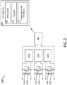
- the current measurement and ground fault detection system/circuitry 200 is illustrated in FIG. 2 , in accordance with example embodiments of this disclosure.
- the current measurement and ground fault detection system/circuitry 200 includes a plurality of phase current measurement coils 202 (e.g., coils 202A, 202B, 202C) configured to detect phase currents associated with at least one portion of the multi-phase system 104.
- the phase current measurement coils 202 may be configured to detect currents of respective phases of the multi-phase system 104 (e.g., currents running through respective connectors or transmission lines at the portion of the multi-phase system 104 that the system/circuitry 200 is coupled to).
- the current measurement and ground fault detection system/circuitry 200 further includes a plurality of phase current measurement circuits 300 (e.g., phase current measurement circuitry 300A, 300B, and 300C) and a ground fault detection circuit 400 connected to the phase current measurement coils 202.
- phase current measurement circuits 300 e.g., phase current measurement circuitry 300A, 300B, and 300C
- ground fault detection circuit 400 connected to the phase current measurement coils 202.
- the phase current measurement circuits 300 are configured to measure the phase currents detected by the phase current measurement coils 202.
- each of the phase current measurement coils 202 may be coupled to a respective phase current measurement circuit 300 configured to measure the phase current detected by that phase current measurement coil 202.
- phase current measurement circuits 300A, 300B, and 300C are coupled to and configured to measure the phase currents detected by phase current measurement coils 202A, 202B, and 202C, respectively.
- each of the phase current measurement circuits 300 may be coupled a first end and a second end of the secondary coil of a respective one of the phase current measurement coils 202.
- the ground fault detection circuit 400 is configured to measure a summation of the phase currents detected by the phase current measurement coils 202.
- the ground fault detection circuit 400 can be configured to measure the summation of three phase currents detected by phase current measurement coils 202A, 202B, and 202C.
- the secondary side (i.e., secondary coils) of the phase current measurement coils 202 are connected in series with one another, and the ground fault detection circuit 400 is configured to measure the summation of the phase currents by detecting the current/voltage across the series-connected phase current measurement coils 202. As shown in FIG.
- a first end of phase current measurement coil 202A is coupled to the ground fault detection circuit 400
- a second end of phase current measurement coil 202A is coupled to a first end of phase current measurement coil 202B
- a second end of phase current measurement coil 202B is coupled to a first end of phase current measurement coil 202C
- a second end of phase current measurement coils 202C is coupled to the ground fault detection circuit 400.
- the ground fault detection circuit 400 can measure a summation of the currents/voltages across phase current measurement coils 202A, 202B, and 202C by detecting the current/voltage between the first end of phase current measurement coil 202A and the second end of phase current measurement coils 202C.
- the current measurement and ground fault detection system/circuitry 200 further includes a plurality of shunt resistors 204 (e.g., shunt resistors 204A, 204B, and 204C) coupled to respective phase current measurement coils 202.
- shunt resistors 204 e.g., shunt resistors 204A, 204B, and 204C
- each of the phase current measurement coils 202 may be connected in parallel with a respective shunt resistor 204.
- phase current measurement coil 202A is connected in parallel with shunt resistor 204A
- phase current measurement coil 202B is connected in parallel with shunt resistor 204B
- phase current measurement coil 202C is connected in parallel with shunt resistor 204C.
- the voltage drop across each shunt resistor 204 is associated with the current detected by the phase current measurement coil 202 that is coupled to the shunt resistor 204.
- the voltage drop across shunt resistor 204A is associated with the current detected by phase current measurement coil 202A
- the voltage drop across shunt resistor 204B is associated with the current detected by phase current measurement coil 202B
- the voltage drop across shunt resistor 204C is associated with the current detected by phase current measurement coil 202C.
- each of the phase current measurement circuits 300 is configured to measure a phase current detected by a respective one of the phase current measurement coils 202 by detecting a voltage drop across the respective one of the shunt resistors 204 (sometimes referred to as the "sense" resistors).
- each of the phase current measurement circuits 300 includes a differential amplifier 302 configured to detect the voltage drop across the respective one of the shunt resistors 204.
- each of the phase current measurement circuits 300 further includes an active rectifier 304 (e.g., based on operational amplifiers) and a low pass filter 306 in series with the differential amplifier 302.
- each of the phase current measurement circuits 300 further includes a buffer amplifier 308 configured to amplify an output (DC) signal from the low pass filter 306 before the output signal is fed into the controller 206.
- the buffer amplifier 308 can be configured to adjust (e.g., amplify or attenuate) the output signal based on the application (e.g., for input to a controller, or for input to another circuit or system).
- the ground fault detection circuit 400 can measure a summation of the currents/voltages across the series-connected phase current measurement coils 202A, 202B, and 202C by detecting the current/voltage between the first end of phase current measurement coil 202A and the second end of phase current measurement coils 202C.
- the shunt resistors 204 are also connected in series with one another, and the ground fault detection circuit 400 is configured to measure the summation of the phase currents by detecting a voltage drop across the shunt resistors 204.
- the ground fault detection circuit 400 may include a differential amplifier 402 configured to detect the voltage drop across the phase current measurement coils 202 and/or their respective shunt resistors 204.
- the amplification level (e.g., gain or power level) of differential amplifier 402 of the ground fault detection circuit 400 may be higher than an amplification level of the differential amplifiers 302 of the current measurement circuits 300.
- the ground fault detection circuit 400 further includes an active rectifier 404 and a low pass filter 406 in series with the differential amplifier 402. The signal from the differential amplifier 402 may be fed through the active rectifier 404 to obtain a DC signal which is then filtered by the low pass filter 406 to an average voltage level to condition the signal for input to the controller 206.
- the ground fault detection circuit 400 further includes a buffer amplifier 408 configured to amplify an output signal (e.g., the DC signal) from the low pass filter 406 before the output signal is fed into the controller 206.
- the buffer amplifier 408 can be configured to adjust (e.g., amplify or attenuate) the output signal based on the application (e.g., for input to a controller, or for input to another circuit or system).
- the outputs of the phase current measurement circuits 300 and the ground fault detection circuit 400 are fed into the controller 206.
- the controller 206 can be configured to determine phase currents based on the outputs from the phase current measurement circuits 300.
- the controller 206 can also be configured to detect ground faults based on the output of the ground fault detection circuit 400. For example, the controller 206 may detect a ground fault when the output of the ground fault detection circuit 400 is a non-zero output or is indicative of a non-zero summation of currents detected by the phase current measurement coils 202.
- the controller 206 may include at least one processor 208, memory 210, and a communication interface 212.
- the processor 208 provides processing functionality for at least the controller 206 and can include any number of processors, micro-controllers, circuitry, field programmable gate array (FPGA) or other processing systems, and resident or external memory for storing data, executable code, and other information accessed or generated by the controller 206.
- the processor 208 can execute one or more software programs embodied in a non-transitory computer readable medium (e.g., memory 210) that implement techniques described herein.
- the processor 208 is not limited by the materials from which it is formed, or the processing mechanisms employed therein and, as such, can be implemented via semiconductor(s) and/or transistors (e.g., using electronic integrated circuit (IC) components), and so forth.
- the memory 210 can be an example of tangible, computer-readable storage medium that provides storage functionality to store various data and/or program code associated with operation of the controller 206/processor 208, such as software programs and/or code segments, or other data to instruct the processor 208, and possibly other components of the controller 206, to perform the functionality described herein.
- the memory 210 can store data, such as a program of instructions for operating the controller 206, including its components (e.g., processor 208, communication interface 212, etc.), and so forth.
- a single memory 210 is described, a wide variety of types and combinations of memory (e.g., tangible, non-transitory memory) can be employed.
- the memory 210 can be integral with the processor 208, can comprise stand-alone memory, or can be a combination of both. Some examples of the memory 210 can include removable and non-removable memory components, such as random-access memory (RAM), read-only memory (ROM), flash memory (e.g., a secure digital (SD) memory card, a mini-SD memory card, and/or a micro-SD memory card), solid-state drive (SSD) memory, magnetic memory, optical memory, universal serial bus (USB) memory devices, hard disk memory, external memory, and so forth.
- RAM random-access memory
- ROM read-only memory
- flash memory e.g., a secure digital (SD) memory card, a mini-SD memory card, and/or a micro-SD memory card
- SSD solid-state drive
- magnetic memory magnetic memory
- optical memory optical memory
- USB universal serial bus
- the communication interface 212 can be operatively configured to communicate with components of the controller 206.
- the communication interface 212 can be configured to retrieve data from the processor 208 or other devices (e.g., phase current measurement circuits 300, ground fault detection circuit 400, etc.), transmit data for storage in the memory 210, retrieve data from storage in the memory 210, and so forth.
- the communication interface 212 can also be communicatively coupled with the processor 208 to facilitate data transfer between components of the controller 206 and the processor 208. It should be noted that while the communication interface 212 is described as a component of the controller 206, one or more components of the communication interface 212 can be implemented as external components communicatively coupled to the controller 206 via a wired and/or wireless connection.
- the controller 206 can also include and/or connect to one or more input/output (I/O) devices (e.g., human machine interface (HMI) devices) via the communication interface 212.
- I/O input/output
- the communication interface 212 may include a transmitter, receiver, transceiver, physical connection interface, or any combination thereof.
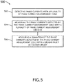
- FIG. 5 illustrates an example implementation of a method 500 that employs the current measurement and ground fault detection system/circuitry 200 described herein.
- operations of disclosed processes e.g., method 500 may be performed in an arbitrary order, unless otherwise provided in the claims.
- the method 500 includes detecting phase currents with a plurality of phase current measurement coils 202.
- the phase current measurement coils 202 may be configured to detect currents of respective phases of a multi-phase system 104 (e.g., currents running through respective connectors or transmission lines at a portion of the multi-phase system 104 that the phase current measurement coils 202 are coupled to).
- the method 500 includes measuring the phase currents detected by the phase current measurement coils 202 with a plurality of phase current measurement circuits 300.
- the phase current measurement circuits 300 may output current measurement signals to a controller 206.
- the controller 206 may determine phase current measurements based on the current measurement signals from the phase current measurement circuits 300.
- the method 500 includes measuring a summation of the phase currents detected by the phase current measurement coils 202 with a ground fault detection circuit 400.
- a ground fault may be detected when the summation of the phase currents is a non-zero value (indicating the presence of a leakage current).
- the ground fault detection circuit 400 may output a signal associated with a detected voltage drop or current across all the phase current measurement coils 202 to the controller 206.
- the controller 206 may detect a ground fault when the output of the ground fault detection circuit 400 is a non-zero output or is indicative of a non-zero summation of currents detected by the phase current measurement coils 202.
- the method 500 may further include any step or operation implied or required by the embodiments of the current measurement and ground fault detection system/circuitry 200 described herein.
- the current measurement and ground fault detection system/circuitry 200 can also include any additional component or functionality expressed or implied by the method 500.
- embodiments of the methods according to the inventive concepts disclosed herein may include one or more of the steps described herein. Further, such steps may be carried out in any desired order and two or more of the steps may be carried out simultaneously with one another. Two or more of the steps disclosed herein may be combined in a single step, and in some embodiments, one or more of the steps may be carried out as two or more sub-steps. Further, other steps or sub-steps may be carried in addition to, or as substitutes to one or more of the steps disclosed herein.
- inventive concepts disclosed herein are well adapted to achieve the objectives and to attain the advantages mentioned herein as well as those inherent in the inventive concepts disclosed herein. While presently preferred embodiments of the inventive concepts disclosed herein have been described for purposes of this disclosure, it will be understood that numerous changes may be made which will readily suggest themselves to those skilled in the art and which are accomplished within the scope of the invention as defined by the claims.
Landscapes
- Physics & Mathematics (AREA)
- General Physics & Mathematics (AREA)
- Engineering & Computer Science (AREA)
- Power Engineering (AREA)
- Testing Of Short-Circuits, Discontinuities, Leakage, Or Incorrect Line Connections (AREA)
- Emergency Protection Circuit Devices (AREA)
Abstract
Description
- An oven (or any other device) may employ current measurement coils to measure the currents through respective phases of a multi-phase system that powers one or more components of the oven. These coils effectively implement transformers that divide the current by a fixed factor. The lower current can then be fed through a resistor (optionally with a rectifier in front) and the voltage over the resistor is then an indicator of the current flowing.
- Older ovens only make use of a current measurement per power phase. In newer ovens, it may be advantageous to also implement ground fault detection systems/circuitry to detect current leaking, for instance, through chassis.
- In an aspect, embodiments of the inventive concepts disclosed herein are directed to a system for current measurement and ground fault detection. In embodiments, the system includes a plurality of phase current measurement coils configured to detect phase currents associated with at least one portion of a multi-phase system. The system further includes a plurality of phase current measurement circuits and a ground fault detection circuit connected to the phase current measurement coils. The phase current measurement circuits are configured to measure the phase currents detected by the phase current measurement coils, and the ground fault detection circuit is configured to measure a summation of the phase currents detected by the phase current measurement coils.
- In another aspect, embodiments of the inventive concepts disclosed herein are directed to a device that includes circuitry for current measurement and ground fault detection. In embodiments, the device includes one or more components that are powered by a multi-phase system. The device further includes a plurality of phase current measurement coils configured to detect phase currents associated with at least one portion of a multi-phase system. The device further includes a plurality of phase current measurement circuits and a ground fault detection circuit connected to the phase current measurement coils. The phase current measurement circuits are configured to measure the phase currents detected by the phase current measurement coils, and the ground fault detection circuit is configured to measure a summation of the phase currents detected by the phase current measurement coils.
- In another aspect, implementations of the inventive concepts disclosed herein are directed to a method of current measurement and ground fault detection. In implementations, the method includes steps of: detecting phase currents with a plurality of phase current measurement coils; measuring the phase currents detected by the phase current measurement coils with a plurality of phase current measurement circuits; and measuring a summation of the phase currents detected by the phase current measurement coils with a ground fault detection circuit.
- This Summary is provided solely as an introduction to subject matter that is fully described in the Detailed Description and Drawings. The Summary should not be considered to describe essential features nor be used to determine the scope of the Claims. Moreover, it is to be understood that both the foregoing Summary and the following Detailed Description are example and explanatory only and are not necessarily restrictive of the subject matter claimed.
- Implementations of the inventive concepts disclosed herein may be better understood when consideration is given to the following detailed description thereof. Such description makes reference to the included drawings, which are not necessarily to scale, and in which some features may be exaggerated and some features may be omitted or may be represented schematically in the interest of clarity. Like reference numerals in the drawings may represent and refer to the same or similar element, feature, or function. In the drawings:
-
FIG. 1 is a block diagram illustrating a device that includes circuitry for current measurement and ground fault detection, in accordance with example embodiments of this disclosure; -
FIG. 2 is a schematic illustration of a system/circuitry for current measurement and ground fault detection, in accordance with example embodiments of this disclosure; -
FIG. 3 is a schematic illustration of a phase current measurement circuit of the system/circuitry illustrated inFIG. 2 , in accordance with example embodiments of this disclosure; -
FIG. 4 is a schematic illustration of a ground fault detection circuit of the system/circuitry illustrated inFIG. 2 , in accordance with example embodiments of this disclosure; and -
FIG. 5 is a flow diagram illustrating an example implementation of a method of current measurement and ground fault detection. - Before explaining at least one embodiment of the inventive concepts disclosed herein in detail, it is to be understood that the inventive concepts are not limited in their application to the details of construction and the arrangement of the components or steps or methodologies set forth in the following description or illustrated in the drawings. In the following detailed description of embodiments of the instant inventive concepts, numerous specific details are set forth in order to provide a more thorough understanding of the inventive concepts. However, it will be apparent to one of ordinary skill in the art having the benefit of the instant disclosure that the inventive concepts disclosed herein may be practiced without these specific details. In other instances, well-known features may not be described in detail to avoid unnecessarily complicating the instant disclosure. The inventive concepts disclosed herein are capable of other embodiments or of being practiced or carried out in various ways. Also, it is to be understood that the phraseology and terminology employed herein is for the purpose of description and should not be regarded as limiting.
- As used herein a letter following a reference numeral is intended to reference an embodiment of the feature or element that may be similar, but not necessarily identical, to a previously described element or feature bearing the same reference numeral (e.g., 1, 1a, 1b). Such shorthand notations are used for purposes of convenience only, and should not be construed to limit the inventive concepts disclosed herein in any way unless expressly stated to the contrary.
- Further, unless expressly stated to the contrary, "or" refers to an inclusive or and not to an exclusive or. For example, a condition A or B is satisfied by anyone of the following: A is true (or present) and B is false (or not present), A is false (or not present) and B is true (or present), and both A and B are true (or present).
- In addition, use of the "a" or "an" are employed to describe elements and components of embodiments of the instant inventive concepts. This is done merely for convenience and to give a general sense of the inventive concepts, and "a" and "an" are intended to include one or at least one and the singular also includes the plural unless it is obvious that it is meant otherwise.
- Finally, as used herein any reference to "one embodiment" or "some embodiments" means that a particular element, feature, structure, or characteristic described in connection with the embodiment is included in at least one embodiment of the inventive concepts disclosed herein. The appearances of the phrase "in some embodiments" in various places in the specification are not necessarily all referring to the same embodiment, and embodiments of the inventive concepts disclosed may include one or more of the features expressly described or inherently present herein, or any combination of sub-combination of two or more such features, along with any other features which may not necessarily be expressly described or inherently present in the instant disclosure.
- Broadly, embodiments of the inventive concepts disclosed herein are directed to a system and method for current measurement and ground fault detection using current measurement coils. Older ovens only make use of a current measurement per power phase. In newer ovens, there is a desire to also implement ground fault detection systems/circuitry to detect current leaking. To do this, some ovens include a dedicated three-phase coil for ground fault detection. In such a configuration, all three power phases are fed through the three primary windings of a current measurement coil. The current trough the secondary winding will be the sum of the three primary currents divided by the winding ratio. When the system is functioning properly, the output equals zero. If there is an unbalance and the output is not equal to zero, this indicates the presence a current leak (also known as a ground fault). This method works but requires the addition of another set of coils or multi-phase coil assembly (e.g., three-phase coil) for ground fault detection, that is, in addition to the current measurement coils. To implement current measurement and ground fault detection functions with a reduced set of hardware, the embodiments described herein employ a common set of coils to measure phase currents and detect ground faults for a device that includes a multi-phase power system.
- In embodiments, a plurality of (e.g., three) phase current measurement coils are placed in series so that the current/voltage across the phase current measurement coils is equivalent to a summation of their respective outputs. The sum of these outputs is then amplified to obtain a measurement of the summation of the detected phase currents. In order for this configuration to operate properly, the traditional output of the phase current measurement circuits with the rectifier in front of the resistor is replaced with a rectifier behind the sense resistor because, once rectified, the voltages added together will not be zero in a normal situation (without leakage current). In addition to functioning with less/smaller components, the current measurement and ground fault detection system/circuitry with the rectifier behind the sense resistor also has the advantage of having higher precision at current levels below 1A. The offset created because the phase current measurement coils are placed in series must be removed to be able to read and handle three currents separately. This is accomplished by using three differential amplifiers, for example, by differential amplifiers in each of the phase current measurement circuits.
- Some advantages of the disclosed current measurement and ground fault detection system/circuitry include the following. The current measurement and ground fault detection system/circuitry allows for implementation of ground fault detection without the need of a separate large, heavy, three-phase coil. Instead, the current measurement and ground fault detection system/circuitry makes use of existing phase current measurement coils, only adding some small, light and inexpensive components. The current measurement and ground fault detection system/circuitry also provides improved implementation of the current measurement circuits, with more linear behavior.
-
FIG. 1 is a block diagram illustrating adevice 100 that may include a system/circuitry 200 for current measurement and ground fault detection, in accordance with example embodiments of this disclosure. In embodiments, thedevice 100 is coupled to a power supply 102 (e.g., a power supply unit (PSU), or the like) that is coupled to and/or part of a multi-phase system 104 (e.g., a three-phase power system). Themulti-phase system 104 can be configured to power one or more of thedevice components 106. For example, thedevice 100 may comprise an aircraft galley insert including components, such as sensors, actuators, interface devices, controllers, heating/cooling elements, and the like. In an example embodiment, thedevice 100 is an oven with one or more heating elements (components 106) powered by themulti-phase system 104. - The current measurement and ground fault detection system/
circuitry 200 may be coupled to a portion of themulti-phase system 104. For example, in some embodiments, the current measurement and ground fault detection system/circuitry 200 may be coupled to front-end portion of the multi-phase system 104 (e.g., to connectors or transmission lines of the power supply 102). In other embodiments, current measurement and ground fault detection system/circuitry 200 may be coupled to an output portion of the multi-phase system 104 (e.g., to connectors or transmission lines of acomponent 106 powered by the multi-phase system 104). The current measurement and ground fault detection system/circuitry 200 may be coupled to any portion of themulti-phase system 104. For example, in some embodiments, the current measurement and ground fault detection system/circuitry 200 may be coupled to an intermedial portion of the multi-phase system 104 (e.g., to connectors or transmission lines between the front-end portion and the output portion of the multi-phase system 104). - The current measurement and ground fault detection system/
circuitry 200 is illustrated inFIG. 2 , in accordance with example embodiments of this disclosure. In embodiments, the current measurement and ground fault detection system/circuitry 200 includes a plurality of phase current measurement coils 202 (e.g., coils 202A, 202B, 202C) configured to detect phase currents associated with at least one portion of themulti-phase system 104. For example, the phase current measurement coils 202 may be configured to detect currents of respective phases of the multi-phase system 104 (e.g., currents running through respective connectors or transmission lines at the portion of themulti-phase system 104 that the system/circuitry 200 is coupled to). The current measurement and ground fault detection system/circuitry 200 further includes a plurality of phase current measurement circuits 300 (e.g., phasecurrent measurement circuitry fault detection circuit 400 connected to the phase current measurement coils 202. - The phase
current measurement circuits 300 are configured to measure the phase currents detected by the phase current measurement coils 202. For example, each of the phase current measurement coils 202 may be coupled to a respective phasecurrent measurement circuit 300 configured to measure the phase current detected by that phase current measurement coil 202. In an example embodiment, phasecurrent measurement circuits FIG. 2 , each of the phasecurrent measurement circuits 300 may be coupled a first end and a second end of the secondary coil of a respective one of the phase current measurement coils 202. - The ground
fault detection circuit 400 is configured to measure a summation of the phase currents detected by the phase current measurement coils 202. For example, the groundfault detection circuit 400 can be configured to measure the summation of three phase currents detected by phase current measurement coils 202A, 202B, and 202C. In embodiments, the secondary side (i.e., secondary coils) of the phase current measurement coils 202 are connected in series with one another, and the groundfault detection circuit 400 is configured to measure the summation of the phase currents by detecting the current/voltage across the series-connected phase current measurement coils 202. As shown inFIG. 2 , in an example embodiment, a first end of phasecurrent measurement coil 202A is coupled to the groundfault detection circuit 400, a second end of phasecurrent measurement coil 202A is coupled to a first end of phasecurrent measurement coil 202B, a second end of phasecurrent measurement coil 202B is coupled to a first end of phasecurrent measurement coil 202C, and a second end of phase current measurement coils 202C is coupled to the groundfault detection circuit 400. In this configuration, the groundfault detection circuit 400 can measure a summation of the currents/voltages across phase current measurement coils 202A, 202B, and 202C by detecting the current/voltage between the first end of phasecurrent measurement coil 202A and the second end of phase current measurement coils 202C. - In embodiments, the current measurement and ground fault detection system/
circuitry 200 further includes a plurality of shunt resistors 204 (e.g.,shunt resistors respective shunt resistor 204. In an example embodiment, phasecurrent measurement coil 202A is connected in parallel withshunt resistor 204A, phasecurrent measurement coil 202B is connected in parallel withshunt resistor 204B, phasecurrent measurement coil 202C is connected in parallel withshunt resistor 204C. In this configuration, the voltage drop across eachshunt resistor 204 is associated with the current detected by the phase current measurement coil 202 that is coupled to theshunt resistor 204. For example, the voltage drop acrossshunt resistor 204A is associated with the current detected by phasecurrent measurement coil 202A, the voltage drop acrossshunt resistor 204B is associated with the current detected by phasecurrent measurement coil 202B, and the voltage drop acrossshunt resistor 204C is associated with the current detected by phasecurrent measurement coil 202C. - Referring now to
FIG. 3 , each of the phasecurrent measurement circuits 300 is configured to measure a phase current detected by a respective one of the phase current measurement coils 202 by detecting a voltage drop across the respective one of the shunt resistors 204 (sometimes referred to as the "sense" resistors). In embodiments, each of the phasecurrent measurement circuits 300 includes adifferential amplifier 302 configured to detect the voltage drop across the respective one of theshunt resistors 204. A positive consequence of this implementation is a more linear behavior of the circuit (as compared to old methods) due to the replacement of rectifying diodes by electronic rectification with an operational amplifier that creates a high impedance input and the location of the rectification placed behind the sense resistor that improves the linearity of the resistive load (Rshunt 204) visible for the current measurement coils 202 to reduce the measurement error in the current measurement and ground fault detection circuitry/system 200. In embodiments, each of the phasecurrent measurement circuits 300 further includes an active rectifier 304 (e.g., based on operational amplifiers) and alow pass filter 306 in series with thedifferential amplifier 302. The signal from thedifferential amplifier 302 may be fed through theactive rectifier 304 to obtain a DC signal which is then filtered by thelow pass filter 306 to an average voltage level to condition the signal for input to a controller 206 (e.g., a microcontroller, microprocessor, or the like). In some embodiments, each of the phasecurrent measurement circuits 300 further includes abuffer amplifier 308 configured to amplify an output (DC) signal from thelow pass filter 306 before the output signal is fed into thecontroller 206. In general, thebuffer amplifier 308 can be configured to adjust (e.g., amplify or attenuate) the output signal based on the application (e.g., for input to a controller, or for input to another circuit or system). - As indicated above, the ground
fault detection circuit 400 can measure a summation of the currents/voltages across the series-connected phase current measurement coils 202A, 202B, and 202C by detecting the current/voltage between the first end of phasecurrent measurement coil 202A and the second end of phase current measurement coils 202C. In embodiments, theshunt resistors 204 are also connected in series with one another, and the groundfault detection circuit 400 is configured to measure the summation of the phase currents by detecting a voltage drop across theshunt resistors 204. As shown inFIG. 4 , the groundfault detection circuit 400 may include adifferential amplifier 402 configured to detect the voltage drop across the phase current measurement coils 202 and/or theirrespective shunt resistors 204. The amplification level (e.g., gain or power level) ofdifferential amplifier 402 of the groundfault detection circuit 400 may be higher than an amplification level of thedifferential amplifiers 302 of thecurrent measurement circuits 300. In embodiments, the groundfault detection circuit 400 further includes anactive rectifier 404 and alow pass filter 406 in series with thedifferential amplifier 402. The signal from thedifferential amplifier 402 may be fed through theactive rectifier 404 to obtain a DC signal which is then filtered by thelow pass filter 406 to an average voltage level to condition the signal for input to thecontroller 206. In some embodiments, the groundfault detection circuit 400 further includes abuffer amplifier 408 configured to amplify an output signal (e.g., the DC signal) from thelow pass filter 406 before the output signal is fed into thecontroller 206. In general, thebuffer amplifier 408 can be configured to adjust (e.g., amplify or attenuate) the output signal based on the application (e.g., for input to a controller, or for input to another circuit or system). - In some embodiments, the outputs of the phase
current measurement circuits 300 and the groundfault detection circuit 400 are fed into thecontroller 206. Thecontroller 206 can be configured to determine phase currents based on the outputs from the phasecurrent measurement circuits 300. Thecontroller 206 can also be configured to detect ground faults based on the output of the groundfault detection circuit 400. For example, thecontroller 206 may detect a ground fault when the output of the groundfault detection circuit 400 is a non-zero output or is indicative of a non-zero summation of currents detected by the phase current measurement coils 202. - As shown in
FIG. 2 , in some embodiments, thecontroller 206 may include at least oneprocessor 208,memory 210, and acommunication interface 212. Theprocessor 208 provides processing functionality for at least thecontroller 206 and can include any number of processors, micro-controllers, circuitry, field programmable gate array (FPGA) or other processing systems, and resident or external memory for storing data, executable code, and other information accessed or generated by thecontroller 206. Theprocessor 208 can execute one or more software programs embodied in a non-transitory computer readable medium (e.g., memory 210) that implement techniques described herein. Theprocessor 208 is not limited by the materials from which it is formed, or the processing mechanisms employed therein and, as such, can be implemented via semiconductor(s) and/or transistors (e.g., using electronic integrated circuit (IC) components), and so forth. - The
memory 210 can be an example of tangible, computer-readable storage medium that provides storage functionality to store various data and/or program code associated with operation of thecontroller 206/processor 208, such as software programs and/or code segments, or other data to instruct theprocessor 208, and possibly other components of thecontroller 206, to perform the functionality described herein. Thus, thememory 210 can store data, such as a program of instructions for operating thecontroller 206, including its components (e.g.,processor 208,communication interface 212, etc.), and so forth. It should be noted that while asingle memory 210 is described, a wide variety of types and combinations of memory (e.g., tangible, non-transitory memory) can be employed. Thememory 210 can be integral with theprocessor 208, can comprise stand-alone memory, or can be a combination of both. Some examples of thememory 210 can include removable and non-removable memory components, such as random-access memory (RAM), read-only memory (ROM), flash memory (e.g., a secure digital (SD) memory card, a mini-SD memory card, and/or a micro-SD memory card), solid-state drive (SSD) memory, magnetic memory, optical memory, universal serial bus (USB) memory devices, hard disk memory, external memory, and so forth. - The
communication interface 212 can be operatively configured to communicate with components of thecontroller 206. For example, thecommunication interface 212 can be configured to retrieve data from theprocessor 208 or other devices (e.g., phasecurrent measurement circuits 300, groundfault detection circuit 400, etc.), transmit data for storage in thememory 210, retrieve data from storage in thememory 210, and so forth. Thecommunication interface 212 can also be communicatively coupled with theprocessor 208 to facilitate data transfer between components of thecontroller 206 and theprocessor 208. It should be noted that while thecommunication interface 212 is described as a component of thecontroller 206, one or more components of thecommunication interface 212 can be implemented as external components communicatively coupled to thecontroller 206 via a wired and/or wireless connection. Thecontroller 206 can also include and/or connect to one or more input/output (I/O) devices (e.g., human machine interface (HMI) devices) via thecommunication interface 212. In embodiments, thecommunication interface 212 may include a transmitter, receiver, transceiver, physical connection interface, or any combination thereof. -
FIG. 5 illustrates an example implementation of amethod 500 that employs the current measurement and ground fault detection system/circuitry 200 described herein. In general, operations of disclosed processes (e.g., method 500) may be performed in an arbitrary order, unless otherwise provided in the claims. - At
step 502, themethod 500 includes detecting phase currents with a plurality of phase current measurement coils 202. For example, the phase current measurement coils 202 may be configured to detect currents of respective phases of a multi-phase system 104 (e.g., currents running through respective connectors or transmission lines at a portion of themulti-phase system 104 that the phase current measurement coils 202 are coupled to). - At
step 504, themethod 500 includes measuring the phase currents detected by the phase current measurement coils 202 with a plurality of phasecurrent measurement circuits 300. In some implementations, the phasecurrent measurement circuits 300 may output current measurement signals to acontroller 206. Thecontroller 206 may determine phase current measurements based on the current measurement signals from the phasecurrent measurement circuits 300. - At
step 506, themethod 500 includes measuring a summation of the phase currents detected by the phase current measurement coils 202 with a groundfault detection circuit 400. In implementations, a ground fault may be detected when the summation of the phase currents is a non-zero value (indicating the presence of a leakage current). For example, the groundfault detection circuit 400 may output a signal associated with a detected voltage drop or current across all the phase current measurement coils 202 to thecontroller 206. Thecontroller 206 may detect a ground fault when the output of the groundfault detection circuit 400 is a non-zero output or is indicative of a non-zero summation of currents detected by the phase current measurement coils 202. - The
method 500 may further include any step or operation implied or required by the embodiments of the current measurement and ground fault detection system/circuitry 200 described herein. The current measurement and ground fault detection system/circuitry 200 can also include any additional component or functionality expressed or implied by themethod 500. - It is to be understood that embodiments of the methods according to the inventive concepts disclosed herein may include one or more of the steps described herein. Further, such steps may be carried out in any desired order and two or more of the steps may be carried out simultaneously with one another. Two or more of the steps disclosed herein may be combined in a single step, and in some embodiments, one or more of the steps may be carried out as two or more sub-steps. Further, other steps or sub-steps may be carried in addition to, or as substitutes to one or more of the steps disclosed herein.
- From the above description, it is clear that the inventive concepts disclosed herein are well adapted to achieve the objectives and to attain the advantages mentioned herein as well as those inherent in the inventive concepts disclosed herein. While presently preferred embodiments of the inventive concepts disclosed herein have been described for purposes of this disclosure, it will be understood that numerous changes may be made which will readily suggest themselves to those skilled in the art and which are accomplished within the scope of the invention as defined by the claims.
Claims (12)
- A system for current measurement and ground fault detection, comprising:a plurality of phase current measurement coils (202) configured to detect phase currents associated with at least one portion of a multi-phase system;a plurality of phase current measurement circuits (300) connected to the phase current measurement coils and configured to measure the phase currents detected by the phase current measurement coils; anda ground fault detection circuit (400) connected to the phase current measurement coils and configured to measure a summation of the phase currents detected by the phase current measurement coils.
- The system of claim 1, wherein the multi-phase system is a three-phase system.
- The system of claim 1 or 2, further comprising a plurality of shunt resistors (204), wherein each of the phase current measurement coils is connected in parallel with a respective one of the shunt resistors.
- The system of claim 3, wherein each of the phase current measurement circuits is configured to measure a phase current detected by a respective one of the phase current measurement coils by detecting a voltage drop across the respective one of the shunt resistors.
- The system of claim 4, wherein each of the phase current measurement circuits includes:a differential amplifier (302) configured to detect the voltage drop across the respective one of the shunt resistors; andan active rectifier (304) and a low pass filter (306) in series with the differential amplifier.
- The system of claim 5, wherein each of the phase current measurement circuits further includes a buffer amplifier (408) configured to amplify an output signal from the low pass filter before the output signal is fed into a controller.
- The system of claim 3, 4, 5 or 6, wherein the shunt resistors are connected in series with one another, and the ground fault detection circuit is configured to measure the summation of the phase currents by detecting a voltage drop across the shunt resistors.
- The system of claim 7, wherein the ground fault detection circuit includes:a differential amplifier (402) configured to detect the voltage drop across the shunt resistors; andan active rectifier (404) and a low pass filter (406) in series with the differential amplifier.
- The system of claim 8, wherein the ground fault detection circuit further includes a buffer amplifier (408) configured to amplify an output signal from the low pass filter before the output signal is fed into a controller (206).
- A device, comprising:one or more components; anda system (200) as claimed in any preceding claim for current measurement and ground fault detection.
- The device of claim 10, wherein the device is an oven, and the one or more components comprise one or more heating elements.
- A method of current measurement and ground fault detection, comprising:detecting phase currents with a plurality of phase current measurement coils;measuring the phase currents detected by the phase current measurement coils with a plurality of phase current measurement circuits; andmeasuring a summation of the phase currents detected by the phase current measurement coils with a ground fault detection circuit.
Applications Claiming Priority (1)
| Application Number | Priority Date | Filing Date | Title |
|---|---|---|---|
| US16/261,755 US10884070B2 (en) | 2019-01-30 | 2019-01-30 | System and method for ground fault detection using current measurement coils |
Publications (2)
| Publication Number | Publication Date |
|---|---|
| EP3690454A1 true EP3690454A1 (en) | 2020-08-05 |
| EP3690454B1 EP3690454B1 (en) | 2023-10-11 |
Family
ID=69411300
Family Applications (1)
| Application Number | Title | Priority Date | Filing Date |
|---|---|---|---|
| EP20154560.5A Active EP3690454B1 (en) | 2019-01-30 | 2020-01-30 | System and method for ground fault detection using current measurement coils |
Country Status (3)
| Country | Link |
|---|---|
| US (1) | US10884070B2 (en) |
| EP (1) | EP3690454B1 (en) |
| CN (1) | CN111505528B (en) |
Families Citing this family (1)
| Publication number | Priority date | Publication date | Assignee | Title |
|---|---|---|---|---|
| FI130150B (en) * | 2022-02-11 | 2023-03-15 | Safegrid Oy | METHOD AND DEVICE FOR FAULT DETECTION IN A DISTRIBUTION NETWORK |
Citations (3)
| Publication number | Priority date | Publication date | Assignee | Title |
|---|---|---|---|---|
| JPH01243816A (en) * | 1988-03-23 | 1989-09-28 | Kawamura Denki Sangyo Kk | Earth leakage breaker |
| US20070182401A1 (en) * | 2004-03-04 | 2007-08-09 | Siemens Aktiengesellschaft | Three- or four-pole low-voltage power switch with rogowski coils operating as current sensors |
| US20120176120A1 (en) * | 2011-01-12 | 2012-07-12 | Schneider Electric USA, Inc. | System and method for monitoring current drawn by a protected load in a self-powered electronic protection device |
Family Cites Families (7)
| Publication number | Priority date | Publication date | Assignee | Title |
|---|---|---|---|---|
| US5206587A (en) * | 1990-03-30 | 1993-04-27 | Mitchell Rose | Inductive displacement transducer having telescoping probe assembly |
| CN102577070B (en) * | 2009-09-28 | 2014-08-27 | 大金工业株式会社 | Phase current detection device and power conversion device using same |
| GB201120295D0 (en) * | 2011-11-24 | 2012-01-04 | Metroic Ltd | Current measurement apparatus |
| US8796982B2 (en) * | 2011-12-15 | 2014-08-05 | Eaton Corporation | System and method for detecting phase loss and diagnosing DC link capacitor health in an adjustable speed drive |
| DE102014224639A1 (en) * | 2014-12-02 | 2016-06-02 | Robert Bosch Gmbh | Method and monitoring device for detecting a fault current for a control device for controlling a multiphase actuator |
| US10274530B2 (en) * | 2015-07-22 | 2019-04-30 | Honeywell International Inc. | System and method for dynamic ground fault detection |
| US10845393B2 (en) * | 2017-09-11 | 2020-11-24 | Analog Devices International Limited Company | Current measurement |
-
2019
- 2019-01-30 US US16/261,755 patent/US10884070B2/en active Active
- 2019-12-13 CN CN201911278481.1A patent/CN111505528B/en active Active
-
2020
- 2020-01-30 EP EP20154560.5A patent/EP3690454B1/en active Active
Patent Citations (3)
| Publication number | Priority date | Publication date | Assignee | Title |
|---|---|---|---|---|
| JPH01243816A (en) * | 1988-03-23 | 1989-09-28 | Kawamura Denki Sangyo Kk | Earth leakage breaker |
| US20070182401A1 (en) * | 2004-03-04 | 2007-08-09 | Siemens Aktiengesellschaft | Three- or four-pole low-voltage power switch with rogowski coils operating as current sensors |
| US20120176120A1 (en) * | 2011-01-12 | 2012-07-12 | Schneider Electric USA, Inc. | System and method for monitoring current drawn by a protected load in a self-powered electronic protection device |
Non-Patent Citations (1)
| Title |
|---|
| LEHTONEN MATTI ET AL: "Simple fault path indication techniques for earth faults", 2014 ELECTRIC POWER QUALITY AND SUPPLY RELIABILITY CONFERENCE (PQ), IEEE, 11 June 2014 (2014-06-11), pages 371 - 378, XP032625903, ISBN: 978-1-4799-5020-1, [retrieved on 20140725], DOI: 10.1109/PQ.2014.6866844 * |
Also Published As
| Publication number | Publication date |
|---|---|
| EP3690454B1 (en) | 2023-10-11 |
| US20200241064A1 (en) | 2020-07-30 |
| US10884070B2 (en) | 2021-01-05 |
| CN111505528A (en) | 2020-08-07 |
| CN111505528B (en) | 2025-05-16 |
Similar Documents
| Publication | Publication Date | Title |
|---|---|---|
| EP3690464A1 (en) | System and method for ground fault detection using hall effect sensors | |
| EP3130931B1 (en) | Leakage current detection circuit, direct-current high-voltage system, and leakage current detection method and device | |
| US9046431B2 (en) | Single ear stator antenna for wireless torque measurement system | |
| US10054648B2 (en) | Power source voltage detection apparatus | |
| US9268347B2 (en) | Implementing dynamic regulator output current limiting | |
| CN105425007A (en) | Shunt Current Measurement With Temperature Compensation | |
| TW201606493A (en) | USB power port control | |
| JP2015129704A (en) | Motor drive device having insulation deterioration detection function and motor insulation resistance detection method | |
| EP3690454B1 (en) | System and method for ground fault detection using current measurement coils | |
| CN103827676A (en) | System for measuring current and method of manufacturing same | |
| CN105242104A (en) | Current detection method, current detection device, and current detector | |
| US9638734B2 (en) | Electrical current system including voltage drop component | |
| US20160025790A1 (en) | Short detection bus | |
| US10581348B2 (en) | Speed detection circuits for permanent magnet alternators | |
| MY197715A (en) | Voltage sensor diagnostic device and voltage sensor diagnostic method | |
| CN106885965B (en) | Device and method for fault detection of frequency converter | |
| US11442092B2 (en) | Power conversion device and method for detecting magnetic saturation of common-mode reactor | |
| CN115524528A (en) | Device and method for detecting motor current | |
| KR20160071480A (en) | Method and apparatus for measuring current of motor | |
| KR102562500B1 (en) | Methods and Apparatuses for sensing current using Op Amp | |
| EP3599716B1 (en) | Fault isolation for pulse width modulated three phase motor systems | |
| EP2667469A1 (en) | High precision clipping regulator circuit | |
| WO2024040626A1 (en) | Temperature measurement method and apparatus based on synchronous detection | |
| US12085594B2 (en) | Method and circuit arrangement for ascertaining a type and value of an input voltage | |
| CN105846852A (en) | Radio frequency device and adjusting method thereof |
Legal Events
| Date | Code | Title | Description |
|---|---|---|---|
| PUAI | Public reference made under article 153(3) epc to a published international application that has entered the european phase |
Free format text: ORIGINAL CODE: 0009012 |
|
| STAA | Information on the status of an ep patent application or granted ep patent |
Free format text: STATUS: THE APPLICATION HAS BEEN PUBLISHED |
|
| AK | Designated contracting states |
Kind code of ref document: A1 Designated state(s): AL AT BE BG CH CY CZ DE DK EE ES FI FR GB GR HR HU IE IS IT LI LT LU LV MC MK MT NL NO PL PT RO RS SE SI SK SM TR |
|
| AX | Request for extension of the european patent |
Extension state: BA ME |
|
| STAA | Information on the status of an ep patent application or granted ep patent |
Free format text: STATUS: REQUEST FOR EXAMINATION WAS MADE |
|
| 17P | Request for examination filed |
Effective date: 20210205 |
|
| RBV | Designated contracting states (corrected) |
Designated state(s): AL AT BE BG CH CY CZ DE DK EE ES FI FR GB GR HR HU IE IS IT LI LT LU LV MC MK MT NL NO PL PT RO RS SE SI SK SM TR |
|
| RAP1 | Party data changed (applicant data changed or rights of an application transferred) |
Owner name: B/E AEROSPACE, INC. |
|
| RIC1 | Information provided on ipc code assigned before grant |
Ipc: H02H 3/32 20060101ALI20230323BHEP Ipc: H02H 3/16 20060101ALI20230323BHEP Ipc: H02H 3/00 20060101ALI20230323BHEP Ipc: G01R 31/52 20200101ALI20230323BHEP Ipc: G01R 19/10 20060101AFI20230323BHEP |
|
| GRAP | Despatch of communication of intention to grant a patent |
Free format text: ORIGINAL CODE: EPIDOSNIGR1 |
|
| STAA | Information on the status of an ep patent application or granted ep patent |
Free format text: STATUS: GRANT OF PATENT IS INTENDED |
|
| INTG | Intention to grant announced |
Effective date: 20230509 |
|
| GRAS | Grant fee paid |
Free format text: ORIGINAL CODE: EPIDOSNIGR3 |
|
| GRAA | (expected) grant |
Free format text: ORIGINAL CODE: 0009210 |
|
| STAA | Information on the status of an ep patent application or granted ep patent |
Free format text: STATUS: THE PATENT HAS BEEN GRANTED |
|
| AK | Designated contracting states |
Kind code of ref document: B1 Designated state(s): AL AT BE BG CH CY CZ DE DK EE ES FI FR GB GR HR HU IE IS IT LI LT LU LV MC MK MT NL NO PL PT RO RS SE SI SK SM TR |
|
| REG | Reference to a national code |
Ref country code: GB Ref legal event code: FG4D |
|
| REG | Reference to a national code |
Ref country code: CH Ref legal event code: EP |
|
| REG | Reference to a national code |
Ref country code: DE Ref legal event code: R096 Ref document number: 602020018871 Country of ref document: DE |
|
| P01 | Opt-out of the competence of the unified patent court (upc) registered |
Effective date: 20230922 |
|
| REG | Reference to a national code |
Ref country code: NL Ref legal event code: FP |
|
| REG | Reference to a national code |
Ref country code: IE Ref legal event code: FG4D |
|
| REG | Reference to a national code |
Ref country code: LT Ref legal event code: MG9D |
|
| REG | Reference to a national code |
Ref country code: AT Ref legal event code: MK05 Ref document number: 1620703 Country of ref document: AT Kind code of ref document: T Effective date: 20231011 |
|
| PG25 | Lapsed in a contracting state [announced via postgrant information from national office to epo] |
Ref country code: GR Free format text: LAPSE BECAUSE OF FAILURE TO SUBMIT A TRANSLATION OF THE DESCRIPTION OR TO PAY THE FEE WITHIN THE PRESCRIBED TIME-LIMIT Effective date: 20240112 |
|
| PG25 | Lapsed in a contracting state [announced via postgrant information from national office to epo] |
Ref country code: IS Free format text: LAPSE BECAUSE OF FAILURE TO SUBMIT A TRANSLATION OF THE DESCRIPTION OR TO PAY THE FEE WITHIN THE PRESCRIBED TIME-LIMIT Effective date: 20240211 |
|
| PG25 | Lapsed in a contracting state [announced via postgrant information from national office to epo] |
Ref country code: LT Free format text: LAPSE BECAUSE OF FAILURE TO SUBMIT A TRANSLATION OF THE DESCRIPTION OR TO PAY THE FEE WITHIN THE PRESCRIBED TIME-LIMIT Effective date: 20231011 |
|
| PG25 | Lapsed in a contracting state [announced via postgrant information from national office to epo] |
Ref country code: AT Free format text: LAPSE BECAUSE OF FAILURE TO SUBMIT A TRANSLATION OF THE DESCRIPTION OR TO PAY THE FEE WITHIN THE PRESCRIBED TIME-LIMIT Effective date: 20231011 |
|
| PG25 | Lapsed in a contracting state [announced via postgrant information from national office to epo] |
Ref country code: ES Free format text: LAPSE BECAUSE OF FAILURE TO SUBMIT A TRANSLATION OF THE DESCRIPTION OR TO PAY THE FEE WITHIN THE PRESCRIBED TIME-LIMIT Effective date: 20231011 |
|
| PG25 | Lapsed in a contracting state [announced via postgrant information from national office to epo] |
Ref country code: LT Free format text: LAPSE BECAUSE OF FAILURE TO SUBMIT A TRANSLATION OF THE DESCRIPTION OR TO PAY THE FEE WITHIN THE PRESCRIBED TIME-LIMIT Effective date: 20231011 Ref country code: IS Free format text: LAPSE BECAUSE OF FAILURE TO SUBMIT A TRANSLATION OF THE DESCRIPTION OR TO PAY THE FEE WITHIN THE PRESCRIBED TIME-LIMIT Effective date: 20240211 Ref country code: GR Free format text: LAPSE BECAUSE OF FAILURE TO SUBMIT A TRANSLATION OF THE DESCRIPTION OR TO PAY THE FEE WITHIN THE PRESCRIBED TIME-LIMIT Effective date: 20240112 Ref country code: ES Free format text: LAPSE BECAUSE OF FAILURE TO SUBMIT A TRANSLATION OF THE DESCRIPTION OR TO PAY THE FEE WITHIN THE PRESCRIBED TIME-LIMIT Effective date: 20231011 Ref country code: BG Free format text: LAPSE BECAUSE OF FAILURE TO SUBMIT A TRANSLATION OF THE DESCRIPTION OR TO PAY THE FEE WITHIN THE PRESCRIBED TIME-LIMIT Effective date: 20240111 Ref country code: AT Free format text: LAPSE BECAUSE OF FAILURE TO SUBMIT A TRANSLATION OF THE DESCRIPTION OR TO PAY THE FEE WITHIN THE PRESCRIBED TIME-LIMIT Effective date: 20231011 Ref country code: PT Free format text: LAPSE BECAUSE OF FAILURE TO SUBMIT A TRANSLATION OF THE DESCRIPTION OR TO PAY THE FEE WITHIN THE PRESCRIBED TIME-LIMIT Effective date: 20240212 |
|
| PG25 | Lapsed in a contracting state [announced via postgrant information from national office to epo] |
Ref country code: SE Free format text: LAPSE BECAUSE OF FAILURE TO SUBMIT A TRANSLATION OF THE DESCRIPTION OR TO PAY THE FEE WITHIN THE PRESCRIBED TIME-LIMIT Effective date: 20231011 Ref country code: RS Free format text: LAPSE BECAUSE OF FAILURE TO SUBMIT A TRANSLATION OF THE DESCRIPTION OR TO PAY THE FEE WITHIN THE PRESCRIBED TIME-LIMIT Effective date: 20231011 Ref country code: PL Free format text: LAPSE BECAUSE OF FAILURE TO SUBMIT A TRANSLATION OF THE DESCRIPTION OR TO PAY THE FEE WITHIN THE PRESCRIBED TIME-LIMIT Effective date: 20231011 Ref country code: NO Free format text: LAPSE BECAUSE OF FAILURE TO SUBMIT A TRANSLATION OF THE DESCRIPTION OR TO PAY THE FEE WITHIN THE PRESCRIBED TIME-LIMIT Effective date: 20240111 Ref country code: LV Free format text: LAPSE BECAUSE OF FAILURE TO SUBMIT A TRANSLATION OF THE DESCRIPTION OR TO PAY THE FEE WITHIN THE PRESCRIBED TIME-LIMIT Effective date: 20231011 Ref country code: HR Free format text: LAPSE BECAUSE OF FAILURE TO SUBMIT A TRANSLATION OF THE DESCRIPTION OR TO PAY THE FEE WITHIN THE PRESCRIBED TIME-LIMIT Effective date: 20231011 |
|
| PG25 | Lapsed in a contracting state [announced via postgrant information from national office to epo] |
Ref country code: DK Free format text: LAPSE BECAUSE OF FAILURE TO SUBMIT A TRANSLATION OF THE DESCRIPTION OR TO PAY THE FEE WITHIN THE PRESCRIBED TIME-LIMIT Effective date: 20231011 |
|
| REG | Reference to a national code |
Ref country code: DE Ref legal event code: R097 Ref document number: 602020018871 Country of ref document: DE |
|
| PG25 | Lapsed in a contracting state [announced via postgrant information from national office to epo] |
Ref country code: CZ Free format text: LAPSE BECAUSE OF FAILURE TO SUBMIT A TRANSLATION OF THE DESCRIPTION OR TO PAY THE FEE WITHIN THE PRESCRIBED TIME-LIMIT Effective date: 20231011 |
|
| PG25 | Lapsed in a contracting state [announced via postgrant information from national office to epo] |
Ref country code: SK Free format text: LAPSE BECAUSE OF FAILURE TO SUBMIT A TRANSLATION OF THE DESCRIPTION OR TO PAY THE FEE WITHIN THE PRESCRIBED TIME-LIMIT Effective date: 20231011 |
|
| PG25 | Lapsed in a contracting state [announced via postgrant information from national office to epo] |
Ref country code: SM Free format text: LAPSE BECAUSE OF FAILURE TO SUBMIT A TRANSLATION OF THE DESCRIPTION OR TO PAY THE FEE WITHIN THE PRESCRIBED TIME-LIMIT Effective date: 20231011 Ref country code: SK Free format text: LAPSE BECAUSE OF FAILURE TO SUBMIT A TRANSLATION OF THE DESCRIPTION OR TO PAY THE FEE WITHIN THE PRESCRIBED TIME-LIMIT Effective date: 20231011 Ref country code: RO Free format text: LAPSE BECAUSE OF FAILURE TO SUBMIT A TRANSLATION OF THE DESCRIPTION OR TO PAY THE FEE WITHIN THE PRESCRIBED TIME-LIMIT Effective date: 20231011 Ref country code: IT Free format text: LAPSE BECAUSE OF FAILURE TO SUBMIT A TRANSLATION OF THE DESCRIPTION OR TO PAY THE FEE WITHIN THE PRESCRIBED TIME-LIMIT Effective date: 20231011 Ref country code: EE Free format text: LAPSE BECAUSE OF FAILURE TO SUBMIT A TRANSLATION OF THE DESCRIPTION OR TO PAY THE FEE WITHIN THE PRESCRIBED TIME-LIMIT Effective date: 20231011 Ref country code: DK Free format text: LAPSE BECAUSE OF FAILURE TO SUBMIT A TRANSLATION OF THE DESCRIPTION OR TO PAY THE FEE WITHIN THE PRESCRIBED TIME-LIMIT Effective date: 20231011 Ref country code: CZ Free format text: LAPSE BECAUSE OF FAILURE TO SUBMIT A TRANSLATION OF THE DESCRIPTION OR TO PAY THE FEE WITHIN THE PRESCRIBED TIME-LIMIT Effective date: 20231011 |
|
| PLBE | No opposition filed within time limit |
Free format text: ORIGINAL CODE: 0009261 |
|
| STAA | Information on the status of an ep patent application or granted ep patent |
Free format text: STATUS: NO OPPOSITION FILED WITHIN TIME LIMIT |
|
| PG25 | Lapsed in a contracting state [announced via postgrant information from national office to epo] |
Ref country code: MC Free format text: LAPSE BECAUSE OF FAILURE TO SUBMIT A TRANSLATION OF THE DESCRIPTION OR TO PAY THE FEE WITHIN THE PRESCRIBED TIME-LIMIT Effective date: 20231011 |
|
| PG25 | Lapsed in a contracting state [announced via postgrant information from national office to epo] |
Ref country code: MC Free format text: LAPSE BECAUSE OF FAILURE TO SUBMIT A TRANSLATION OF THE DESCRIPTION OR TO PAY THE FEE WITHIN THE PRESCRIBED TIME-LIMIT Effective date: 20231011 |
|
| REG | Reference to a national code |
Ref country code: CH Ref legal event code: PL |
|
| PG25 | Lapsed in a contracting state [announced via postgrant information from national office to epo] |
Ref country code: LU Free format text: LAPSE BECAUSE OF NON-PAYMENT OF DUE FEES Effective date: 20240130 |
|
| 26N | No opposition filed |
Effective date: 20240712 |
|
| PG25 | Lapsed in a contracting state [announced via postgrant information from national office to epo] |
Ref country code: LU Free format text: LAPSE BECAUSE OF NON-PAYMENT OF DUE FEES Effective date: 20240130 |
|
| PG25 | Lapsed in a contracting state [announced via postgrant information from national office to epo] |
Ref country code: BE Free format text: LAPSE BECAUSE OF NON-PAYMENT OF DUE FEES Effective date: 20240131 |
|
| PG25 | Lapsed in a contracting state [announced via postgrant information from national office to epo] |
Ref country code: CH Free format text: LAPSE BECAUSE OF NON-PAYMENT OF DUE FEES Effective date: 20240131 |
|
| PG25 | Lapsed in a contracting state [announced via postgrant information from national office to epo] |
Ref country code: SI Free format text: LAPSE BECAUSE OF FAILURE TO SUBMIT A TRANSLATION OF THE DESCRIPTION OR TO PAY THE FEE WITHIN THE PRESCRIBED TIME-LIMIT Effective date: 20231011 |
|
| PG25 | Lapsed in a contracting state [announced via postgrant information from national office to epo] |
Ref country code: SI Free format text: LAPSE BECAUSE OF FAILURE TO SUBMIT A TRANSLATION OF THE DESCRIPTION OR TO PAY THE FEE WITHIN THE PRESCRIBED TIME-LIMIT Effective date: 20231011 Ref country code: CH Free format text: LAPSE BECAUSE OF NON-PAYMENT OF DUE FEES Effective date: 20240131 Ref country code: BE Free format text: LAPSE BECAUSE OF NON-PAYMENT OF DUE FEES Effective date: 20240131 |
|
| REG | Reference to a national code |
Ref country code: BE Ref legal event code: MM Effective date: 20240131 |
|
| PG25 | Lapsed in a contracting state [announced via postgrant information from national office to epo] |
Ref country code: IE Free format text: LAPSE BECAUSE OF NON-PAYMENT OF DUE FEES Effective date: 20240130 |
|
| PG25 | Lapsed in a contracting state [announced via postgrant information from national office to epo] |
Ref country code: IE Free format text: LAPSE BECAUSE OF NON-PAYMENT OF DUE FEES Effective date: 20240130 |
|
| PG25 | Lapsed in a contracting state [announced via postgrant information from national office to epo] |
Ref country code: CY Free format text: LAPSE BECAUSE OF FAILURE TO SUBMIT A TRANSLATION OF THE DESCRIPTION OR TO PAY THE FEE WITHIN THE PRESCRIBED TIME-LIMIT; INVALID AB INITIO Effective date: 20200130 |
|
| PG25 | Lapsed in a contracting state [announced via postgrant information from national office to epo] |
Ref country code: HU Free format text: LAPSE BECAUSE OF FAILURE TO SUBMIT A TRANSLATION OF THE DESCRIPTION OR TO PAY THE FEE WITHIN THE PRESCRIBED TIME-LIMIT; INVALID AB INITIO Effective date: 20200130 |
|
| PG25 | Lapsed in a contracting state [announced via postgrant information from national office to epo] |
Ref country code: FI Free format text: LAPSE BECAUSE OF FAILURE TO SUBMIT A TRANSLATION OF THE DESCRIPTION OR TO PAY THE FEE WITHIN THE PRESCRIBED TIME-LIMIT Effective date: 20231011 |
|
| PG25 | Lapsed in a contracting state [announced via postgrant information from national office to epo] |
Ref country code: TR Free format text: LAPSE BECAUSE OF FAILURE TO SUBMIT A TRANSLATION OF THE DESCRIPTION OR TO PAY THE FEE WITHIN THE PRESCRIBED TIME-LIMIT Effective date: 20231011 |
|
| PGFP | Annual fee paid to national office [announced via postgrant information from national office to epo] |
Ref country code: GB Payment date: 20251220 Year of fee payment: 7 |
|
| PGFP | Annual fee paid to national office [announced via postgrant information from national office to epo] |
Ref country code: NL Payment date: 20251217 Year of fee payment: 7 Ref country code: FR Payment date: 20251217 Year of fee payment: 7 |
|
| PGFP | Annual fee paid to national office [announced via postgrant information from national office to epo] |
Ref country code: DE Payment date: 20251217 Year of fee payment: 7 |