EP3690401A1 - Arithmetic apparatus - Google Patents
Arithmetic apparatus Download PDFInfo
- Publication number
- EP3690401A1 EP3690401A1 EP20154329.5A EP20154329A EP3690401A1 EP 3690401 A1 EP3690401 A1 EP 3690401A1 EP 20154329 A EP20154329 A EP 20154329A EP 3690401 A1 EP3690401 A1 EP 3690401A1
- Authority
- EP
- European Patent Office
- Prior art keywords
- road edge
- vehicle
- presumed
- unit
- road
- Prior art date
- Legal status (The legal status is an assumption and is not a legal conclusion. Google has not performed a legal analysis and makes no representation as to the accuracy of the status listed.)
- Withdrawn
Links
Images



Classifications
-
- B—PERFORMING OPERATIONS; TRANSPORTING
- B62—LAND VEHICLES FOR TRAVELLING OTHERWISE THAN ON RAILS
- B62D—MOTOR VEHICLES; TRAILERS
- B62D6/00—Arrangements for automatically controlling steering depending on driving conditions sensed and responded to, e.g. control circuits
- B62D6/002—Arrangements for automatically controlling steering depending on driving conditions sensed and responded to, e.g. control circuits computing target steering angles for front or rear wheels
- B62D6/006—Arrangements for automatically controlling steering depending on driving conditions sensed and responded to, e.g. control circuits computing target steering angles for front or rear wheels using a measured or estimated road friction coefficient
-
- G—PHYSICS
- G01—MEASURING; TESTING
- G01C—MEASURING DISTANCES, LEVELS OR BEARINGS; SURVEYING; NAVIGATION; GYROSCOPIC INSTRUMENTS; PHOTOGRAMMETRY OR VIDEOGRAMMETRY
- G01C21/00—Navigation; Navigational instruments not provided for in groups G01C1/00 - G01C19/00
- G01C21/26—Navigation; Navigational instruments not provided for in groups G01C1/00 - G01C19/00 specially adapted for navigation in a road network
- G01C21/34—Route searching; Route guidance
- G01C21/36—Input/output arrangements for on-board computers
- G01C21/3602—Input other than that of destination using image analysis, e.g. detection of road signs, lanes, buildings, real preceding vehicles using a camera
-
- G—PHYSICS
- G01—MEASURING; TESTING
- G01D—MEASURING NOT SPECIALLY ADAPTED FOR A SPECIFIC VARIABLE; ARRANGEMENTS FOR MEASURING TWO OR MORE VARIABLES NOT COVERED IN A SINGLE OTHER SUBCLASS; TARIFF METERING APPARATUS; MEASURING OR TESTING NOT OTHERWISE PROVIDED FOR
- G01D21/00—Measuring or testing not otherwise provided for
- G01D21/02—Measuring two or more variables by means not covered by a single other subclass
-
- G—PHYSICS
- G01—MEASURING; TESTING
- G01S—RADIO DIRECTION-FINDING; RADIO NAVIGATION; DETERMINING DISTANCE OR VELOCITY BY USE OF RADIO WAVES; LOCATING OR PRESENCE-DETECTING BY USE OF THE REFLECTION OR RERADIATION OF RADIO WAVES; ANALOGOUS ARRANGEMENTS USING OTHER WAVES
- G01S17/00—Systems using the reflection or reradiation of electromagnetic waves other than radio waves, e.g. lidar systems
- G01S17/02—Systems using the reflection of electromagnetic waves other than radio waves
- G01S17/06—Systems determining position data of a target
- G01S17/42—Simultaneous measurement of distance and other co-ordinates
-
- G—PHYSICS
- G01—MEASURING; TESTING
- G01S—RADIO DIRECTION-FINDING; RADIO NAVIGATION; DETERMINING DISTANCE OR VELOCITY BY USE OF RADIO WAVES; LOCATING OR PRESENCE-DETECTING BY USE OF THE REFLECTION OR RERADIATION OF RADIO WAVES; ANALOGOUS ARRANGEMENTS USING OTHER WAVES
- G01S17/00—Systems using the reflection or reradiation of electromagnetic waves other than radio waves, e.g. lidar systems
- G01S17/86—Combinations of lidar systems with systems other than lidar, radar or sonar, e.g. with direction finders
-
- G—PHYSICS
- G01—MEASURING; TESTING
- G01S—RADIO DIRECTION-FINDING; RADIO NAVIGATION; DETERMINING DISTANCE OR VELOCITY BY USE OF RADIO WAVES; LOCATING OR PRESENCE-DETECTING BY USE OF THE REFLECTION OR RERADIATION OF RADIO WAVES; ANALOGOUS ARRANGEMENTS USING OTHER WAVES
- G01S17/00—Systems using the reflection or reradiation of electromagnetic waves other than radio waves, e.g. lidar systems
- G01S17/88—Lidar systems specially adapted for specific applications
- G01S17/93—Lidar systems specially adapted for specific applications for anti-collision purposes
- G01S17/931—Lidar systems specially adapted for specific applications for anti-collision purposes of land vehicles
-
- G—PHYSICS
- G01—MEASURING; TESTING
- G01S—RADIO DIRECTION-FINDING; RADIO NAVIGATION; DETERMINING DISTANCE OR VELOCITY BY USE OF RADIO WAVES; LOCATING OR PRESENCE-DETECTING BY USE OF THE REFLECTION OR RERADIATION OF RADIO WAVES; ANALOGOUS ARRANGEMENTS USING OTHER WAVES
- G01S7/00—Details of systems according to groups G01S13/00, G01S15/00, G01S17/00
- G01S7/48—Details of systems according to groups G01S13/00, G01S15/00, G01S17/00 of systems according to group G01S17/00
- G01S7/4808—Evaluating distance, position or velocity data
-
- G—PHYSICS
- G06—COMPUTING OR CALCULATING; COUNTING
- G06V—IMAGE OR VIDEO RECOGNITION OR UNDERSTANDING
- G06V10/00—Arrangements for image or video recognition or understanding
- G06V10/40—Extraction of image or video features
- G06V10/46—Descriptors for shape, contour or point-related descriptors, e.g. scale invariant feature transform [SIFT] or bags of words [BoW]; Salient regional features
- G06V10/462—Salient features, e.g. scale invariant feature transforms [SIFT]
-
- G—PHYSICS
- G06—COMPUTING OR CALCULATING; COUNTING
- G06V—IMAGE OR VIDEO RECOGNITION OR UNDERSTANDING
- G06V10/00—Arrangements for image or video recognition or understanding
- G06V10/40—Extraction of image or video features
- G06V10/56—Extraction of image or video features relating to colour
-
- G—PHYSICS
- G06—COMPUTING OR CALCULATING; COUNTING
- G06V—IMAGE OR VIDEO RECOGNITION OR UNDERSTANDING
- G06V20/00—Scenes; Scene-specific elements
- G06V20/50—Context or environment of the image
- G06V20/56—Context or environment of the image exterior to a vehicle by using sensors mounted on the vehicle
- G06V20/588—Recognition of the road, e.g. of lane markings; Recognition of the vehicle driving pattern in relation to the road
Definitions
- the present invention relates to an arithmetic apparatus.
- PTL 1 discloses a mine machine including: a traveling apparatus capable of running on tracks of a mine; a car body supported by the traveling apparatus; a noncontact sensor which is provided at a front part of the car body and is capable of detecting an object(s) in a detection area in a noncontact manner, wherein the track in front of the car body and side edges of the track are located in the detection area while the traveling apparatus is traveling; an obstacle detection unit that detects an obstacle(s) on the track in front of the car body on the basis of an output signal of the noncontact sensor; a distance detection unit that detects a distance to a wall part beside the track on the basis of the output signal of the noncontact sensor; and a traveling control unit that controls the traveling apparatus on the basis of a detection result of at least one of the obstacle detection unit and the distance detection unit.
- the invention described in PTL 1 can be improved in a case when sufficient information about the wall surface cannot be obtained.
- An arithmetic apparatus includes: a sensor information acquisition unit that acquires sensor information from a sensor which is mounted in a vehicle and collects information about surroundings of the vehicle as the sensor information; a feature point extraction unit that extracts feature points of an object by using the sensor information; a target point detection unit that expresses positions of the feature points extracted by the feature point extraction unit with spatial coordinates and detects them as target points; a road edge presumption unit that presumes a segment between the target points, which are continuously aligned, as a road edge; and a blockade judgment unit that judges whether or not to cancel the road edge presumed by the road edge presumption unit, on the basis of information about an area behind the presumed road edge, which is obtained from the sensor information, wherein the area behind the road edge is an area opposite is an area opposite the sensor at the other side of the presumed road edge.
- Whether the presumed road edge is true or false can be determined in a simplified manner according to the present invention when sufficient information about the wall surface cannot be obtained.
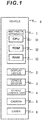
- Fig. 1 is a hardware configuration diagram of a vehicle 9 in which an arithmetic apparatus 1 is mounted.
- the vehicle 9 includes the arithmetic apparatus 1, a display device 2, a vehicle sensor 3, a vehicle control unit 4, a camera 5, and a laser 6.
- the vehicle 9 will be hereinafter sometimes referred to as the "driver's own vehicle” 9 in order to distinguish it from other vehicles.
- the arithmetic apparatus 1 includes a CPU 11 which is a central processing unit, a ROM 12 which is a read-only storage device, and a RAM 13 which is a readable/writable storage device; and implements a plurality of functions described later by the CPU 11 expanding and executing programs, which are stored in the ROM 12, on the RAM 13.
- the arithmetic apparatus 1 presumes walls existing around the vehicle 9 by using outputs from the camera 5 and the laser 6 and outputs the existence of the walls to the display device 2 and the vehicle control unit 4.
- the arithmetic apparatus 1 may be implemented by an FPGA (Field ProgrAmmAble GAte ArrAy) which is a rewritable logical circuit or an ASIC (ApplicAtion Specific IntegrAted Circuit) which is an integrated circuit for specified usage, instead of the combination of the CPU 11, the ROM 12, and the RAM 13.
- the arithmetic apparatus 1 may be implemented by a combination with a different configuration such as a combination of the CPU 11, the ROM 12, the RAM 13, and the FPGA instead of the combination of the CPU 11, the ROM 12, and the RAM 13.
- the display device 2 is, for example, a liquid crystal display and displays pictures based on operating commands of the arithmetic apparatus 1.
- the vehicle sensor 3 is a sensor for measuring the operations of the vehicle 9 and includes, for example, a speedometer for measuring the speed of the vehicle 9 and an angle meter for measuring a rotation angle of a steering wheel.
- the vehicle sensor 3 may only be required to be capable of obtaining information which enables the calculation of the position and attitude of the vehicle 9; and may be configured of, for example, a receiver which configures a satellite navigation system such as a GPS, and a gyroscope for measuring an attitude angle.
- the vehicle sensor 3 outputs the information obtained by measurement to the arithmetic apparatus 1.
- the vehicle control unit 4 controls power sources such as an engine and a motor, a braking system, and a steering gear of the vehicle 9. However, the vehicle control unit 4 may be operated effectively only when specifically indicated by a user; and the vehicle control unit 4 does not have to be included the vehicle 9. The vehicle control unit 4 controls the vehicle 9 based on the existence of a wall(s), which exists around the vehicle 9, by using outputs from the arithmetic apparatus 1.
- the camera 5 outputs an image(s) obtained by photographing the surroundings of the vehicle 9 as a captured image(s) to the arithmetic apparatus 1.
- the laser 6 is a laser range finder and emits a laser light at least at a plurality of angles in a horizontal direction and outputs the distance to an obstacle at each angle as obstacle information to the arithmetic apparatus 1.
- the captured image(s) and the obstacle information will be hereinafter also referred to as the "sensor information.”
- Fig. 2 is a functional configuration diagram of the arithmetic apparatus 1.
- the arithmetic apparatus 1 includes, as its functions, a sensor information acquisition unit 111, a vehicle momentum acquisition unit 112, a feature point extraction unit 113, a target point detection unit 115, a road edge presumption unit 116, a road surface presumption unit 117, a blockade judgment unit 118, and an output control unit 119.
- the sensor information acquisition unit 111 acquires the sensor information from the camera 5 and the laser 6.
- the main sensor information of the camera 5 is camera images captured by photographing the scenery in front of the camera.
- the laser 6 acquires laser information, which is obtained by collecting the position and reflection intensity of an object(s) existing in a laser light emission direction from the reflection of the laser light emitted to the surroundings, as its main sensor information.
- the vehicle momentum acquisition unit 112 acquires information of the speed and steering angle of the vehicle from the vehicle sensor 3. Specifically, the vehicle momentum acquisition unit 112 can identify a traveling trajectory of the driver's own vehicle 9 and the position and attitude of the driver's own vehicle 9 at each time of day.
- the vehicle momentum acquisition unit 112 saves the position and attitude of the driver's own vehicle 9 in a storage area which is not illustrated in the drawing so that they can be checked against the sensor information. For example, if a time stamp is included in the sensor information, the vehicle momentum acquisition unit 112 records the position and attitude of the driver's own vehicle 9 together with the time-of-day information. Furthermore, if a serial number indicating the acquisition timing is included in the sensor information, the position and attitude of the driver's own vehicle 9 and the serial number are recorded together with the time-of-day information.
- the feature point extraction unit 113 extracts feature points from images captured by the camera 5.
- the feature point(s) is a characteristic part(s) in an image and is, for example, a corner point of an object which appears in an image.
- the feature point(s) can be identified to a certain degree depending on its characteristics. For example, regarding the corner point(s), the direction of the corner and its outline strength become identifiers of that feature point.
- the Harris operator which is a known technique can be applied to the feature point extraction unit 113.
- the feature point extraction unit 113 may use the obstacle information, which is output from the laser 6, directly as the feature point(s).
- the target point detection unit 115 identifies the spatial coordinates of a feature point(s) extracted by the feature point extraction unit 113 and detects it as a target point.
- a movement of the camera 5 or the laser 6 belonging to the driver's own vehicle 9 a movement of the feature point extracted from the images captured by the camera 5 or the laser information of the laser 6 is determined by its spatial coordinates. So, the target point detection unit 115: derives the spatial coordinates of the relevant feature point by referring to a travel amount of the driver's own vehicle 9, which is acquired from the vehicle sensor 3, and tracking the movement of the feature point extracted by the feature point extraction unit 113; and outputs the feature point, to which this coordinate information is assigned, as the target point.
- the laser 6 can acquire the spatial coordinates of the object as the sensor information, so this may be used as the spatial coordinates to be assigned to the target point.
- the target point detection unit 115 defines a spatial coordinate system by setting, for example, the center position of the vehicle 9 at certain time of day as its origin, the north as a Y-axis, the east as an X-axis, and a vertical upward direction as a Z-axis. Then, every time the feature point extraction unit 113 extracts a feature point, the coordinates of that feature point in the spatial coordinate system are identified according to the position and attitude of the vehicle 9 acquired by the sensor information acquisition unit 111.
- the road edge presumption unit 116 presumes a road edge by using target points detected by the target point detection unit 115.
- the road edge presumption unit 116 presumes a segment(s) between a plurality of target points, which are continuously aligned in the spatial coordinate system, as the road edge. Not only when the plurality of the target points are aligned along a straight line, but also even when the target points are a specified distance away from the straight line, the road edge presumption unit 116 presumes the segment(s) between these target points as the road edge.
- the specified distance may be a fixed value or a variable value. In a case of the variable value, for example, it may be set according to the resolving power of the sensor.
- the road edge presumption result by the road edge presumption unit 116 may sometimes be reversed by the blockade judgment unit 118 and its detailed explanation will be provided later.
- the road surface presumption unit 117 presumes a road surface area by using the sensor information. For example, colors, patterns, shapes, and a light reflection factor can be used for the presumption of the road surface area.
- the road surface presumption unit 117 may presume an area which matches a specified color and/or a specified pattern in an image captured by the camera 5, as the road surface.
- the road surface presumption unit 117 may presume an area which has substantially the same height as that of a bottom face of a tire of the vehicle 9 and extends in a horizontal direction, as the road surface on the basis of height information of the target point.
- a reflection factor of the laser is included in the sensor information which is output from the laser 6, the road surface presumption unit 117 may presume an area within a specified range of the reflection factor as the road surface.
- the blockade judgment unit 118 judges whether blockade characteristics of the road edge presumed by the road edge presumption unit 116 are true or false. In other words, the blockade judgment unit 118 judges whether the segment between the target points, which is determined as the road edge by the road edge presumption unit 116, is truly blocked or not.
- the blockade judgment unit 118 judges the blockade of the road by three methods. The first method is a method to determine that the road is not blocked if another target point is detected in the back side of the presumed road edge. The second method is a method to determine that the road is not blocked if information of the plane of the presumed road edge changes along with the movement of the driver's own vehicle 9.
- the third method is a method to use the presumption result by the road surface presumption unit 117 and determine that the road is not blocked if both the front side and the back side of the presumed road edge are presumed as the road surface. The details of the three methods will be explained later in detail.
- the output control unit 119 outputs the road edge information about the road edge presumed by the road edge presumption unit 116, regarding which the presumption result has not been reversed by the blockade judgment unit 118, to the display device 2 and the vehicle control unit 4. For example, even if the road edge presumption unit 116 presumes the existence of a certain road edge, the output control unit 119 does not output the road edge information if the blockade judgment unit 118 determines that such presumption is erroneous.
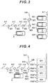
- Fig. 3 to Fig. 5 are schematic diagrams illustrating the operation of the road edge presumption unit 116.
- Fig. 3 is a diagram of a parking facility where the driver's own vehicle 9 is running, as viewed from above;
- Fig. 4 is the target point recognition result by the arithmetic apparatus 1;
- Fig. 5 is the road edge presumption result by the road edge presumption unit 116.
- Walls h11 to h17, pillars h21 to h25, and vehicles h31 to h34 exist in the parking facility illustrated in Fig. 3 .
- the pillars h21 to h25 are illustrated to be relatively large in order to emphasize their existence.
- the walls h11 to h17 are uniform walls without any asperities or patterns.
- the walls h11 to h14 are aligned along a straight line, which turns at the pillar 24 at an angle of 90 degrees and then the wall h15 and the wall h16 exist.
- the driver's own vehicle 9 exists in the center of the lower part of Fig. 3 and travels to the right direction in the drawing.
- the wall h17 exists ahead of the driver's own vehicle 9 and the vehicles h31 to h34 are parked side by side in front of that wall h17 and with their front parts facing the wall h17.
- the right side face of the vehicle h32 is located almost along an extension line from the walls h11 to h14.
- the "wall” will be hereinafter used as having the same meaning as the "road edge.”
- the respective circles illustrated in Fig. 4 are target points detected by the target point detection unit 115.
- FIG. 4 broken lines are used to indicate objects other than the target points in order to show the correspondence with Fig. 3 .
- a plurality of target points can be detected from each pillar h21 to h24, but an explanation will be provided here by assuming, for the purpose of simple explanation, that one target point is detected from each pillar.
- the target points P21 to P24 correspond to the pillars h21 to h24, respectively.
- target points P321 and P322 are recognized for the vehicle h32
- target points P331 and P332 are recognized for the vehicle h33
- target points P341 and P342 are recognized for the vehicle h34.
- the road edge presumption result by the road edge presumption unit 116 is indicated with bold lines and broken lines indicate the correspondence with Fig. 3 and Fig. 4 . All the target points are indicated with the broken lines.
- the road edge presumption unit 116 detects the plurality of target points which are continuously aligned, it presumes segments between these target points as road edges. Therefore, not only the segments between the target points P21 to P24 are presumed as the road edges, but also the segment between the target points P24 and P322 which are accidentally aligned along a straight line is also presumed as the road edge h99.
- the presumed road edge h99 is a road edge which does not actually exist, and this presumption will be canceled by the processing of the blockade judgment unit 118 described later.
- the blockade judgment unit 118 determines that the relevant road edge is not blocked, that is, the presumption by the road edge presumption unit 116 is erroneous if a target point exists behind the road edge presumed by the road edge presumption unit 116.
- the area behind the road edge is an area is opposite the camera 5 and the laser 6 at the other side of the presumed road edge.
- the blockade judgment unit 118 can identify the position of the vehicle 9 when each target point is acquired, that is, the positions of the camera 5 and the laser 6.
- Fig. 6 is a schematic diagram for explaining the first method of the blockade judgment unit 118.
- circles represent target points detected by the target point detection unit 115
- bold lines represent road edges presumed by the road edge presumption unit 116
- long dashed short dashed lines represent auxiliary lines for explanation.
- the vehicle 9 is running in the lower part of the drawing and was located at position 9A at a certain time of day and at position 9B at another time of day.
- target points P411 to P414 and P420 are detected by the target point detection unit 115 and the road edge presumption unit 116 presumes h91 to h93 as road edges is assumed.
- the blockade judgment unit 118 determines that the presumption of the road edges by the road edge presumption unit 116 is erroneous. If the blockade judgment unit 118 determines based on the sensor information obtained when the vehicle 9 is located at the position 9A that the target point P420 is detected, it determines that the presumption of the road edge h91, which is the road edge intersecting with a straight line connecting the positions of the camera 5 and the laser 6 at that time and the target point P420, is erroneous.
- the blockade judgment unit 118 determines based on the sensor information obtained when the vehicle 9 is located at the position 9B that the target point P420 is detected, it determines that the presumption of the road edge h92 is erroneous.
- the auxiliary line extends from the left-side face of the vehicle 9 in Fig. 6 because it is assumed that the camera 5 and the laser 6 for acquiring the information of the left side of the vehicle 9 are mounted on the left side of the vehicle 9. If the camera 5 and the laser 6 were mounted on the front side of the vehicle 9, the auxiliary line would extend from the front side of the vehicle 9.
- Fig. 7 is a diagram illustrating the result obtained by applying the first method of the blockade judgment unit 118 to the road edge presumption result by the road edge presumption unit 116 illustrated in Fig. 5 .
- the target point P321 is detected and the target point P321 exists in the back side of the road edge h99 presumed by the road edge presumption unit 116.
- Fig. 7 shows that a line segment connecting the vehicle 9 and the target point P321 intersects with the road edge h99. Therefore, the blockade judgment unit 118 determines that the presumption regarding the road edge h99 by the road edge presumption unit 116 is erroneous.
- the first method has been explained above.
- the blockade judgment unit 118 calculates a change in the sensor information based on the movement of the vehicle 9 by assuming that the road edge presumed by the road edge presumption unit 116 is a plane which stands perpendicularly to the road surface; and judges whether the road edge presumed by the road edge presumption unit 116 is true or false, on the basis of deviation from a change in the sensor information which is actually obtained. For example, an image of the plane area of the presumed road edge in the captured image obtained before the movement of the vehicle 9 is set as a processing target and an image of that road edge area obtained at the position after the movement is calculated based on the positional relationship and attitude relationship with the vehicle 9 after the movement.
- the blockade judgment unit 118 compares the calculated image with the actually obtained captured image; and if the deviation between them exceeds a specified threshold value, the blockade judgment unit 118 determines that the presumed road edge is false, that is, the presumption of that road edge is erroneous.
- the blockade judgment unit 118 uses the presumption result by the road surface presumption unit 117. If both the front side and the back side of the presumed road edge are presumed as the road surface by the road surface presumption unit 117, the blockade judgment unit 118 determines that the road edge is not blocked.
- Fig. 8 is a schematic diagram for explaining the third method of the blockade judgment unit 118. Since the reference numerals indicated in Fig. 8 are the same as those in Fig. 6 , an explanation about them has been omitted. However, hatching in Fig. 8 indicates an area presumed as the road surface by the road surface presumption unit 117. In this case, since the front side and the back side of the presumed road edge h92 are presumed as the road surface by the road surface presumption unit 117, the blockade judgment unit 118 determines that the presumed road edge h92 is not blocked, that is, the presumption by the road surface presumption unit 117 is erroneous.
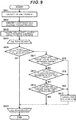
- Fig. 9 is a flowchart illustrating the road edge estimation processing by the arithmetic apparatus 1. This processing is always executed repeatedly in a scene where the road edge is estimated. A subject of each step explained below is the CPU 11.
- the arithmetic apparatus 1 firstly has the sensor information acquisition unit 111 acquire the sensor information. Specifically speaking, the camera 5 captures camera images and the laser 6 acquires the laser information. Then, the feature point extraction unit 113 is used to extract feature points from these camera images and the laser information. Subsequently, the target point detection unit 115 is used to derive the spatial coordinates of the feature points and detects target points. Then, the road edge presumption unit 116: identifies the target points which are aligned continuously in the three-dimensional space or in the two-dimensional plane without heights (S602); and presumes segments between the identified target points as a road edge(s) (S603).
- the arithmetic apparatus 1 executes the processing from S605 to S615 by setting all the segments between the target points presumed as the road edges in S603 and switching the processing target one by one. For example, in the example of Fig. 5 , the arithmetic apparatus 1 sets the road edge h11 as the processing target for the first time and executes the processing of S605 to S615 and then sets the road edge h12 as the processing target and executes the processing of S605 to S615, and then sets all nine road edges as the processing targets in the same manner.
- the arithmetic apparatus 1 judges whether the segment between the target points, which is the processing target, is wider than the width of the driver's own vehicle 9; and if the arithmetic apparatus 1 determines that the segment is wider than the width of the driver's own vehicle 9, the processing proceeds to S611; and if the arithmetic apparatus 1 determines that the width of the segment is equal to or less than the width of the driver's own vehicle 9, the processing proceeds to S620.
- the arithmetic apparatus 1 judges whether another target point exists in the back side of the segment between the target points; and if the arithmetic apparatus 1 determines that another target point exists, the processing proceeds to S615; and if the arithmetic apparatus 1 determines that another target point does not exist, the processing proceeds to S612.
- the arithmetic apparatus 1 assumes that the presumed road edge is a plane perpendicular to the road surface and recognizes that any object appearing in this road edge direction from among the sensor information is located on this plane, and thereby calculates the sensor information after the movement of the vehicle 9 on the basis of the vehicle travel amount. The arithmetic apparatus 1 evaluates deviation between the above calculation result and the actual sensor information.
- the processing proceeds to S615; and if the arithmetic apparatus 1 determines that the deviation between them is equal to or less than the threshold value, the processing proceeds to S613.
- the arithmetic apparatus 1 uses the presumption result by the road surface presumption unit 117 and judges whether both the front side and the back side of the segment between the target points, which is the processing target, are presumed as the road surface or not. If the arithmetic apparatus 1 determines that both of them are presumed as the road surface, the processing proceeds to S615; and if the arithmetic apparatus 1 determines that at least either one of them is not presumed as the road surface, the processing proceeds to S620. In S615, the blockade judgment unit 118 cancels the presumption of the segment between the target points, which is the processing target, as the road edge by the road edge presumption unit 116 and proceeds to S620. Incidentally, S611, S612, and S613 correspond to the first method , the second method, and the third method of the blockade judgment unit 118, respectively.
- the arithmetic apparatus 1 judges whether all the segments between the target points, which were presumed as the road edges in S603, have become the processing targets for S605 to S615. If the arithmetic apparatus 1 determines that there are unprocessed segments between the target points, it sets any one of the unprocessed segments between the target points as the processing target and returns to S605; and if the arithmetic apparatus 1 determines that all the segments between the target points have become the processing targets, it terminates the processing illustrated in Fig. 9 .
- the blockade judgment unit 118 includes the first, second, and third methods. However, the blockade judgment unit 118 may only be required to include at least any one of the above-mentioned methods.
- the blockade judgment unit 118 cancels the presumption by the road edge presumption unit 116.
- the presumption by the road edge presumption unit 116 may be canceled only if the presumption by the road edge presumption unit 116 is denied by the two or more methods.
- the blockade judgment unit 118 may determine according to the second method that the road edge presumed by the road edge presumption unit 116 is false, that, the presumed road edge is not a true road edge. This is because it can be presumed that, for example, if images of a uniform wall without any patterns are captured from different angles, similar pictures would be obtained.
- the blockade judgment unit 118 assumes that the presumed road edge is a plane perpendicular to a road surface; recognizes that an image in a direction of the plane from among the captured images exists at spatial coordinates on the plane; calculates the image on the plane after the vehicle has moved on the basis of the vehicle travel amount; and judges whether or not to cancel the presumed road edge, on the basis of the above-mentioned image and a captured images actually photographed after the vehicle has moved regarding before and after the movement of the vehicle. Therefore, the blockade judgment unit 118 can judge whether the presumed road edge is true or false in a simplified manner.
- the blockade judgment unit 118 may consider the height direction by the first method.
- the road edge presumption unit 116 firstly estimates the height of the road edge by a known method. Then, the blockade judgment unit 118 judges whether or not a straight line connecting the sensor mounted in the vehicle 9 and a target point existing at the back side of the presumed road edge intersects with the presumed road edge.
- the blockade judgment unit 118 determines that the presumption by the road edge presumption unit 116 is erroneous; and if they do not intersect with each other, the blockade judgment unit 118 does not determine that the presumption by the road edge presumption unit 116 is erroneous.
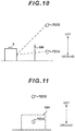
- Fig. 10 and Fig. 11 are diagrams for explaining the first method of the blockade judgment unit 118 according to Variation 4.
- Fig. 10 is a diagram showing the situation in Fig. 7 according to the embodiment as viewed from the lateral side. If the target point P321 is located at the position indicated as P321A at a lower part of the diagram, a line segment connecting the target point P321 and the sensor intersects with the road edge h99 and, therefore, the presumption of the road edge h99 by the road edge presumption unit 116 is determined to be erroneous.
- the target point P321 is located at the position indicated as P321 B in an upper part of the diagram, a line segment connecting the target point P321 and the sensor does not intersect with the road edge h99 and, therefore, the presumption of the road edge h99 by the road edge presumption unit 116 is determined to be not erroneous.
- Fig. 11 is a diagram showing the same situation as that of Fig. 10 as viewed from a different angle and corresponds to an image obtained by cutting off an area around the target point P321 from the image captured by the camera 5.
- the camera 5 is used as the sensor as illustrated in Fig. 11 , it may be only necessary to judge whether or not the area of the presumed road edge h99 overlaps the position of the target point P321 in the captured image.
- the vehicle 9 may not include at least one of the display device 2 and the vehicle control unit 4.
- the vehicle 9 may not include at least one of the camera 5 and the laser 6.
- the vehicle 9 may include other sensors such as an ultrasonic sensor instead of the camera 5 and the laser 6.
Landscapes
- Engineering & Computer Science (AREA)
- Physics & Mathematics (AREA)
- General Physics & Mathematics (AREA)
- Remote Sensing (AREA)
- Radar, Positioning & Navigation (AREA)
- Multimedia (AREA)
- Theoretical Computer Science (AREA)
- Electromagnetism (AREA)
- Computer Networks & Wireless Communication (AREA)
- Computer Vision & Pattern Recognition (AREA)
- Mechanical Engineering (AREA)
- Transportation (AREA)
- Combustion & Propulsion (AREA)
- Chemical & Material Sciences (AREA)
- Mathematical Physics (AREA)
- Automation & Control Theory (AREA)
- Traffic Control Systems (AREA)
- Image Analysis (AREA)
- Optical Radar Systems And Details Thereof (AREA)
- Image Processing (AREA)
Abstract
Description
- The present invention relates to an arithmetic apparatus.
- Technology that detects a road edge(s) such as a wall(s) where a vehicle cannot run by using information collected by a sensor(s) for the purpose of attention reminder for drivers or automatic driving has been being developed. It would be ideal if the detailed information of a wall surface could be obtained by the sensor; however, sufficient information cannot sometimes be obtained depending on the sensor's spatial resolution or the positional relationship between the wall surface and the sensor.
PTL 1 discloses a mine machine including: a traveling apparatus capable of running on tracks of a mine; a car body supported by the traveling apparatus; a noncontact sensor which is provided at a front part of the car body and is capable of detecting an object(s) in a detection area in a noncontact manner, wherein the track in front of the car body and side edges of the track are located in the detection area while the traveling apparatus is traveling; an obstacle detection unit that detects an obstacle(s) on the track in front of the car body on the basis of an output signal of the noncontact sensor; a distance detection unit that detects a distance to a wall part beside the track on the basis of the output signal of the noncontact sensor; and a traveling control unit that controls the traveling apparatus on the basis of a detection result of at least one of the obstacle detection unit and the distance detection unit. - PTL 1:
WO2015/102096 - The invention described in
PTL 1 can be improved in a case when sufficient information about the wall surface cannot be obtained. - An arithmetic apparatus according to a first aspect of the present invention includes: a sensor information acquisition unit that acquires sensor information from a sensor which is mounted in a vehicle and collects information about surroundings of the vehicle as the sensor information; a feature point extraction unit that extracts feature points of an object by using the sensor information; a target point detection unit that expresses positions of the feature points extracted by the feature point extraction unit with spatial coordinates and detects them as target points; a road edge presumption unit that presumes a segment between the target points, which are continuously aligned, as a road edge; and a blockade judgment unit that judges whether or not to cancel the road edge presumed by the road edge presumption unit, on the basis of information about an area behind the presumed road edge, which is obtained from the sensor information, wherein the area behind the road edge is an area opposite is an area opposite the sensor at the other side of the presumed road edge.
- Whether the presumed road edge is true or false can be determined in a simplified manner according to the present invention when sufficient information about the wall surface cannot be obtained.
-
-
Fig. 1 is a hardware configuration diagram of avehicle 9; -
Fig. 2 is a functional configuration diagram of anarithmetic apparatus 1; -
Fig. 3 is a diagram of a parking facility where thevehicle 9 is running, as viewed from above; -
Fig. 4 is a diagram illustrating a target point recognition result by thearithmetic apparatus 1; -
Fig. 5 is a diagram illustrating a road edge presumption result by a roadedge presumption unit 116; -
Fig. 6 is a schematic diagram for explaining a first method of a blockade judgment unit 118; -
Fig. 7 is a diagram illustrating the result obtained by applying the first method of the blockade judgment unit 118 to the road edge presumption result by the roadedge presumption unit 116 illustrated inFig. 5 ; -
Fig. 8 is a schematic diagram for explaining a third method of the blockade judgment unit 118; -
Fig. 9 is a flowchart illustrating road edge estimation processing by thearithmetic apparatus 1; -
Fig. 10 is a diagram for explaining the first method inVariation 4; and -
Fig. 11 is a diagram illustrating the same situation as that ofFig. 10 as viewed from a different angle from that ofFig. 10 . - Embodiments of an arithmetic apparatus will be explained with reference to
Fig. 1 to Fig. 9 . -
Fig. 1 is a hardware configuration diagram of avehicle 9 in which anarithmetic apparatus 1 is mounted. Thevehicle 9 includes thearithmetic apparatus 1, adisplay device 2, avehicle sensor 3, avehicle control unit 4, acamera 5, and alaser 6. Incidentally, thevehicle 9 will be hereinafter sometimes referred to as the "driver's own vehicle" 9 in order to distinguish it from other vehicles. - The arithmetic apparatus 1: includes a
CPU 11 which is a central processing unit, aROM 12 which is a read-only storage device, and aRAM 13 which is a readable/writable storage device; and implements a plurality of functions described later by theCPU 11 expanding and executing programs, which are stored in theROM 12, on theRAM 13. Thearithmetic apparatus 1 presumes walls existing around thevehicle 9 by using outputs from thecamera 5 and thelaser 6 and outputs the existence of the walls to thedisplay device 2 and thevehicle control unit 4. - However, the
arithmetic apparatus 1 may be implemented by an FPGA (Field ProgrAmmAble GAte ArrAy) which is a rewritable logical circuit or an ASIC (ApplicAtion Specific IntegrAted Circuit) which is an integrated circuit for specified usage, instead of the combination of theCPU 11, theROM 12, and theRAM 13. Furthermore, thearithmetic apparatus 1 may be implemented by a combination with a different configuration such as a combination of theCPU 11, theROM 12, theRAM 13, and the FPGA instead of the combination of theCPU 11, theROM 12, and theRAM 13. - The
display device 2 is, for example, a liquid crystal display and displays pictures based on operating commands of thearithmetic apparatus 1. Thevehicle sensor 3 is a sensor for measuring the operations of thevehicle 9 and includes, for example, a speedometer for measuring the speed of thevehicle 9 and an angle meter for measuring a rotation angle of a steering wheel. However, the vehicle sensor 3: may only be required to be capable of obtaining information which enables the calculation of the position and attitude of thevehicle 9; and may be configured of, for example, a receiver which configures a satellite navigation system such as a GPS, and a gyroscope for measuring an attitude angle. Thevehicle sensor 3 outputs the information obtained by measurement to thearithmetic apparatus 1. - The
vehicle control unit 4 controls power sources such as an engine and a motor, a braking system, and a steering gear of thevehicle 9. However, thevehicle control unit 4 may be operated effectively only when specifically indicated by a user; and thevehicle control unit 4 does not have to be included thevehicle 9. Thevehicle control unit 4 controls thevehicle 9 based on the existence of a wall(s), which exists around thevehicle 9, by using outputs from thearithmetic apparatus 1. - The
camera 5 outputs an image(s) obtained by photographing the surroundings of thevehicle 9 as a captured image(s) to thearithmetic apparatus 1. Thelaser 6 is a laser range finder and emits a laser light at least at a plurality of angles in a horizontal direction and outputs the distance to an obstacle at each angle as obstacle information to thearithmetic apparatus 1. Incidentally, the captured image(s) and the obstacle information will be hereinafter also referred to as the "sensor information." -
Fig. 2 is a functional configuration diagram of thearithmetic apparatus 1. Thearithmetic apparatus 1 includes, as its functions, a sensorinformation acquisition unit 111, a vehiclemomentum acquisition unit 112, a featurepoint extraction unit 113, a targetpoint detection unit 115, a roadedge presumption unit 116, a road surface presumption unit 117, a blockade judgment unit 118, and an output control unit 119. - The sensor
information acquisition unit 111 acquires the sensor information from thecamera 5 and thelaser 6. The main sensor information of thecamera 5 is camera images captured by photographing the scenery in front of the camera. Thelaser 6 acquires laser information, which is obtained by collecting the position and reflection intensity of an object(s) existing in a laser light emission direction from the reflection of the laser light emitted to the surroundings, as its main sensor information. The vehiclemomentum acquisition unit 112 acquires information of the speed and steering angle of the vehicle from thevehicle sensor 3. Specifically, the vehiclemomentum acquisition unit 112 can identify a traveling trajectory of the driver'sown vehicle 9 and the position and attitude of the driver'sown vehicle 9 at each time of day. The vehiclemomentum acquisition unit 112 saves the position and attitude of the driver'sown vehicle 9 in a storage area which is not illustrated in the drawing so that they can be checked against the sensor information. For example, if a time stamp is included in the sensor information, the vehiclemomentum acquisition unit 112 records the position and attitude of the driver'sown vehicle 9 together with the time-of-day information. Furthermore, if a serial number indicating the acquisition timing is included in the sensor information, the position and attitude of the driver'sown vehicle 9 and the serial number are recorded together with the time-of-day information. - The feature
point extraction unit 113 extracts feature points from images captured by thecamera 5. The feature point(s) is a characteristic part(s) in an image and is, for example, a corner point of an object which appears in an image. Furthermore, the feature point(s) can be identified to a certain degree depending on its characteristics. For example, regarding the corner point(s), the direction of the corner and its outline strength become identifiers of that feature point. For example, the Harris operator which is a known technique can be applied to the featurepoint extraction unit 113. However, the featurepoint extraction unit 113 may use the obstacle information, which is output from thelaser 6, directly as the feature point(s). - The target
point detection unit 115 identifies the spatial coordinates of a feature point(s) extracted by the featurepoint extraction unit 113 and detects it as a target point. Regarding a movement of thecamera 5 or thelaser 6 belonging to the driver'sown vehicle 9, a movement of the feature point extracted from the images captured by thecamera 5 or the laser information of thelaser 6 is determined by its spatial coordinates. So, the target point detection unit 115: derives the spatial coordinates of the relevant feature point by referring to a travel amount of the driver'sown vehicle 9, which is acquired from thevehicle sensor 3, and tracking the movement of the feature point extracted by the featurepoint extraction unit 113; and outputs the feature point, to which this coordinate information is assigned, as the target point. Incidentally, thelaser 6 can acquire the spatial coordinates of the object as the sensor information, so this may be used as the spatial coordinates to be assigned to the target point. Under this circumstances, the targetpoint detection unit 115 defines a spatial coordinate system by setting, for example, the center position of thevehicle 9 at certain time of day as its origin, the north as a Y-axis, the east as an X-axis, and a vertical upward direction as a Z-axis. Then, every time the featurepoint extraction unit 113 extracts a feature point, the coordinates of that feature point in the spatial coordinate system are identified according to the position and attitude of thevehicle 9 acquired by the sensorinformation acquisition unit 111. - The road
edge presumption unit 116 presumes a road edge by using target points detected by the targetpoint detection unit 115. The roadedge presumption unit 116 presumes a segment(s) between a plurality of target points, which are continuously aligned in the spatial coordinate system, as the road edge. Not only when the plurality of the target points are aligned along a straight line, but also even when the target points are a specified distance away from the straight line, the roadedge presumption unit 116 presumes the segment(s) between these target points as the road edge. Incidentally, the specified distance may be a fixed value or a variable value. In a case of the variable value, for example, it may be set according to the resolving power of the sensor. Furthermore, even if the distance between the target points is wider than the width of thevehicle 9, the segment between these target points may be presumed as the road edge. Incidentally, the road edge presumption result by the roadedge presumption unit 116 may sometimes be reversed by the blockade judgment unit 118 and its detailed explanation will be provided later. - The road surface presumption unit 117 presumes a road surface area by using the sensor information. For example, colors, patterns, shapes, and a light reflection factor can be used for the presumption of the road surface area. The road surface presumption unit 117 may presume an area which matches a specified color and/or a specified pattern in an image captured by the
camera 5, as the road surface. The road surface presumption unit 117 may presume an area which has substantially the same height as that of a bottom face of a tire of thevehicle 9 and extends in a horizontal direction, as the road surface on the basis of height information of the target point. When a reflection factor of the laser is included in the sensor information which is output from thelaser 6, the road surface presumption unit 117 may presume an area within a specified range of the reflection factor as the road surface. - The blockade judgment unit 118 judges whether blockade characteristics of the road edge presumed by the road
edge presumption unit 116 are true or false. In other words, the blockade judgment unit 118 judges whether the segment between the target points, which is determined as the road edge by the roadedge presumption unit 116, is truly blocked or not. The blockade judgment unit 118 judges the blockade of the road by three methods. The first method is a method to determine that the road is not blocked if another target point is detected in the back side of the presumed road edge. The second method is a method to determine that the road is not blocked if information of the plane of the presumed road edge changes along with the movement of the driver'sown vehicle 9. The third method is a method to use the presumption result by the road surface presumption unit 117 and determine that the road is not blocked if both the front side and the back side of the presumed road edge are presumed as the road surface. The details of the three methods will be explained later in detail. - The output control unit 119 outputs the road edge information about the road edge presumed by the road
edge presumption unit 116, regarding which the presumption result has not been reversed by the blockade judgment unit 118, to thedisplay device 2 and thevehicle control unit 4. For example, even if the roadedge presumption unit 116 presumes the existence of a certain road edge, the output control unit 119 does not output the road edge information if the blockade judgment unit 118 determines that such presumption is erroneous. -
Fig. 3 to Fig. 5 are schematic diagrams illustrating the operation of the roadedge presumption unit 116.Fig. 3 is a diagram of a parking facility where the driver'sown vehicle 9 is running, as viewed from above;Fig. 4 is the target point recognition result by thearithmetic apparatus 1; andFig. 5 is the road edge presumption result by the roadedge presumption unit 116. - Walls h11 to h17, pillars h21 to h25, and vehicles h31 to h34 exist in the parking facility illustrated in
Fig. 3 . Incidentally, the pillars h21 to h25 are illustrated to be relatively large in order to emphasize their existence. The walls h11 to h17 are uniform walls without any asperities or patterns. The walls h11 to h14 are aligned along a straight line, which turns at thepillar 24 at an angle of 90 degrees and then the wall h15 and the wall h16 exist. The driver'sown vehicle 9 exists in the center of the lower part ofFig. 3 and travels to the right direction in the drawing. The wall h17 exists ahead of the driver'sown vehicle 9 and the vehicles h31 to h34 are parked side by side in front of that wall h17 and with their front parts facing the wall h17. Incidentally, the right side face of the vehicle h32 is located almost along an extension line from the walls h11 to h14. Incidentally, the "wall" will be hereinafter used as having the same meaning as the "road edge." - The respective circles illustrated in
Fig. 4 are target points detected by the targetpoint detection unit 115. Incidentally, inFig. 4 , broken lines are used to indicate objects other than the target points in order to show the correspondence withFig. 3 . Furthermore, a plurality of target points can be detected from each pillar h21 to h24, but an explanation will be provided here by assuming, for the purpose of simple explanation, that one target point is detected from each pillar. The target points P21 to P24 correspond to the pillars h21 to h24, respectively. - Since the pillar h25 and the vehicle h31 cannot be recognized from the driver's
own vehicle 9 due to the existence of, for example, the wall h14, they are indicated with broken lines. Regarding the vehicles h32 to h34, at least both widthwise ends of the rear parts of the vehicles are recognized as target points. Specifically speaking, target points P321 and P322 are recognized for the vehicle h32, target points P331 and P332 are recognized for the vehicle h33, and target points P341 and P342 are recognized for the vehicle h34. - Referring to
Fig. 5 , the road edge presumption result by the roadedge presumption unit 116 is indicated with bold lines and broken lines indicate the correspondence withFig. 3 and Fig. 4 . All the target points are indicated with the broken lines. When the roadedge presumption unit 116 detects the plurality of target points which are continuously aligned, it presumes segments between these target points as road edges. Therefore, not only the segments between the target points P21 to P24 are presumed as the road edges, but also the segment between the target points P24 and P322 which are accidentally aligned along a straight line is also presumed as the road edge h99. Specifically speaking, the presumed road edge h99 is a road edge which does not actually exist, and this presumption will be canceled by the processing of the blockade judgment unit 118 described later. - The three methods for estimating whether the road edge presumed by the blockade judgment unit 118 is true or false will be explained with reference to the relevant drawings. Incidentally, every method uses information about an area behind the road edge.
- Regarding the first method, the blockade judgment unit 118 determines that the relevant road edge is not blocked, that is, the presumption by the road
edge presumption unit 116 is erroneous if a target point exists behind the road edge presumed by the roadedge presumption unit 116. Incidentally, the area behind the road edge is an area is opposite thecamera 5 and thelaser 6 at the other side of the presumed road edge. Furthermore, "behind the road edge" can be also expressed as "the back side of the road edge." Since the vehiclemomentum acquisition unit 112 saves the position and attitude of the driver'sown vehicle 9 so that they can be checked against the sensor information as described earlier, the blockade judgment unit 118 can identify the position of thevehicle 9 when each target point is acquired, that is, the positions of thecamera 5 and thelaser 6. -
Fig. 6 is a schematic diagram for explaining the first method of the blockade judgment unit 118. Referring toFig. 6 , circles represent target points detected by the targetpoint detection unit 115, bold lines represent road edges presumed by the roadedge presumption unit 116, and long dashed short dashed lines represent auxiliary lines for explanation. Thevehicle 9 is running in the lower part of the drawing and was located atposition 9A at a certain time of day and atposition 9B at another time of day. A case where target points P411 to P414 and P420 are detected by the targetpoint detection unit 115 and the roadedge presumption unit 116 presumes h91 to h93 as road edges is assumed. - In this case, since the target point P420 exists behind the road edges presumed by the road
edge presumption unit 116, the blockade judgment unit 118 determines that the presumption of the road edges by the roadedge presumption unit 116 is erroneous. If the blockade judgment unit 118 determines based on the sensor information obtained when thevehicle 9 is located at theposition 9A that the target point P420 is detected, it determines that the presumption of the road edge h91, which is the road edge intersecting with a straight line connecting the positions of thecamera 5 and thelaser 6 at that time and the target point P420, is erroneous. Furthermore, if the blockade judgment unit 118 determines based on the sensor information obtained when thevehicle 9 is located at theposition 9B that the target point P420 is detected, it determines that the presumption of the road edge h92 is erroneous. - Incidentally, the auxiliary line extends from the left-side face of the
vehicle 9 inFig. 6 because it is assumed that thecamera 5 and thelaser 6 for acquiring the information of the left side of thevehicle 9 are mounted on the left side of thevehicle 9. If thecamera 5 and thelaser 6 were mounted on the front side of thevehicle 9, the auxiliary line would extend from the front side of thevehicle 9. -
Fig. 7 is a diagram illustrating the result obtained by applying the first method of the blockade judgment unit 118 to the road edge presumption result by the roadedge presumption unit 116 illustrated inFig. 5 . In the examples illustrated inFig. 3 to Fig. 5 , the target point P321 is detected and the target point P321 exists in the back side of the road edge h99 presumed by the roadedge presumption unit 116.Fig. 7 shows that a line segment connecting thevehicle 9 and the target point P321 intersects with the road edge h99. Therefore, the blockade judgment unit 118 determines that the presumption regarding the road edge h99 by the roadedge presumption unit 116 is erroneous. The first method has been explained above. - Regarding the second method, the blockade judgment unit 118: calculates a change in the sensor information based on the movement of the
vehicle 9 by assuming that the road edge presumed by the roadedge presumption unit 116 is a plane which stands perpendicularly to the road surface; and judges whether the road edge presumed by the roadedge presumption unit 116 is true or false, on the basis of deviation from a change in the sensor information which is actually obtained. For example, an image of the plane area of the presumed road edge in the captured image obtained before the movement of thevehicle 9 is set as a processing target and an image of that road edge area obtained at the position after the movement is calculated based on the positional relationship and attitude relationship with thevehicle 9 after the movement. Then, the blockade judgment unit 118 compares the calculated image with the actually obtained captured image; and if the deviation between them exceeds a specified threshold value, the blockade judgment unit 118 determines that the presumed road edge is false, that is, the presumption of that road edge is erroneous. - Regarding the third method, the blockade judgment unit 118 uses the presumption result by the road surface presumption unit 117. If both the front side and the back side of the presumed road edge are presumed as the road surface by the road surface presumption unit 117, the blockade judgment unit 118 determines that the road edge is not blocked.
-
Fig. 8 is a schematic diagram for explaining the third method of the blockade judgment unit 118. Since the reference numerals indicated inFig. 8 are the same as those inFig. 6 , an explanation about them has been omitted. However, hatching inFig. 8 indicates an area presumed as the road surface by the road surface presumption unit 117. In this case, since the front side and the back side of the presumed road edge h92 are presumed as the road surface by the road surface presumption unit 117, the blockade judgment unit 118 determines that the presumed road edge h92 is not blocked, that is, the presumption by the road surface presumption unit 117 is erroneous. -
Fig. 9 is a flowchart illustrating the road edge estimation processing by thearithmetic apparatus 1. This processing is always executed repeatedly in a scene where the road edge is estimated. A subject of each step explained below is theCPU 11. - In S601, the
arithmetic apparatus 1 firstly has the sensorinformation acquisition unit 111 acquire the sensor information. Specifically speaking, thecamera 5 captures camera images and thelaser 6 acquires the laser information. Then, the featurepoint extraction unit 113 is used to extract feature points from these camera images and the laser information. Subsequently, the targetpoint detection unit 115 is used to derive the spatial coordinates of the feature points and detects target points. Then, the road edge presumption unit 116: identifies the target points which are aligned continuously in the three-dimensional space or in the two-dimensional plane without heights (S602); and presumes segments between the identified target points as a road edge(s) (S603). Thearithmetic apparatus 1 executes the processing from S605 to S615 by setting all the segments between the target points presumed as the road edges in S603 and switching the processing target one by one. For example, in the example ofFig. 5 , thearithmetic apparatus 1 sets the road edge h11 as the processing target for the first time and executes the processing of S605 to S615 and then sets the road edge h12 as the processing target and executes the processing of S605 to S615, and then sets all nine road edges as the processing targets in the same manner. - In S605, the
arithmetic apparatus 1 judges whether the segment between the target points, which is the processing target, is wider than the width of the driver'sown vehicle 9; and if thearithmetic apparatus 1 determines that the segment is wider than the width of the driver'sown vehicle 9, the processing proceeds to S611; and if thearithmetic apparatus 1 determines that the width of the segment is equal to or less than the width of the driver'sown vehicle 9, the processing proceeds to S620. In S611, thearithmetic apparatus 1 judges whether another target point exists in the back side of the segment between the target points; and if thearithmetic apparatus 1 determines that another target point exists, the processing proceeds to S615; and if thearithmetic apparatus 1 determines that another target point does not exist, the processing proceeds to S612. In S612, thearithmetic apparatus 1 assumes that the presumed road edge is a plane perpendicular to the road surface and recognizes that any object appearing in this road edge direction from among the sensor information is located on this plane, and thereby calculates the sensor information after the movement of thevehicle 9 on the basis of the vehicle travel amount. Thearithmetic apparatus 1 evaluates deviation between the above calculation result and the actual sensor information. If there is any deviation, it means that the sensor information in this road edge direction is not located on the plane of the road edge. If thearithmetic apparatus 1 determines that the deviation between them is more than a threshold value, the processing proceeds to S615; and if thearithmetic apparatus 1 determines that the deviation between them is equal to or less than the threshold value, the processing proceeds to S613. - In S613, the
arithmetic apparatus 1 uses the presumption result by the road surface presumption unit 117 and judges whether both the front side and the back side of the segment between the target points, which is the processing target, are presumed as the road surface or not. If thearithmetic apparatus 1 determines that both of them are presumed as the road surface, the processing proceeds to S615; and if thearithmetic apparatus 1 determines that at least either one of them is not presumed as the road surface, the processing proceeds to S620. In S615, the blockade judgment unit 118 cancels the presumption of the segment between the target points, which is the processing target, as the road edge by the roadedge presumption unit 116 and proceeds to S620. Incidentally, S611, S612, and S613 correspond to the first method , the second method, and the third method of the blockade judgment unit 118, respectively. - In S620, the
arithmetic apparatus 1 judges whether all the segments between the target points, which were presumed as the road edges in S603, have become the processing targets for S605 to S615. If thearithmetic apparatus 1 determines that there are unprocessed segments between the target points, it sets any one of the unprocessed segments between the target points as the processing target and returns to S605; and if thearithmetic apparatus 1 determines that all the segments between the target points have become the processing targets, it terminates the processing illustrated inFig. 9 . - The following operational advantages can be obtained according to the above-described embodiment.
- (1) The
arithmetic apparatus 1 includes: the sensorinformation acquisition unit 111 that acquires the sensor information from thecamera 5 and thelaser 6 which are mounted in thevehicle 9 and collects information about the surroundings of thevehicle 9 as the sensor information; the featurepoint extraction unit 113 that extracts a feature point(s) of an object(s) by using the sensor information; the targetpoint detection unit 115 that expresses the position(s) of the feature point(s) extracted by the featurepoint extraction unit 113 with spatial coordinates and detects it/them as a target point(s); the roadedge presumption unit 116 that presumes a segment between the target points, which are continuously aligned, as a road edge; and the blockade judgment unit 118 that judges whether or not to cancel the road edge presumed by the roadedge presumption unit 116, on the basis of information about an area behind the presumed road edge, which is obtained from the sensor information. The area behind the road edge is an area opposite the sensor at the other side of the presumed road edge. Therefore, when sufficient information about the wall surface cannot be obtained, whether the presumed road edge is true or false can be judged in a simplified manner. - (2) The blockade judgment unit 118 determines, according to the first method, to cancel the presumed road edge when a target point(s) exist in the area behind the presumed road edge. Therefore, the presumption by the road
edge presumption unit 116 can be evaluated by using the positional relationship between the target points and the vehicle. - (3) The blockade judgment unit 118 determines an area from the road edge presumed by the road
edge presumption unit 116, such as the road edge h99 as illustrated inFig. 7 , to the target points such as the target point P321 in the area behind the presumed road edge as a travelable area. Therefore, the blockade judgment unit 118 not only judges whether the road edge exists or not, but also outputs information about the area where thevehicle 9 can travel, so that it can contribute to the control of thevehicle 9 and the provision of information to the driver. - (4) The
arithmetic apparatus 1 includes the vehiclemomentum acquisition unit 112 which acquires the moving direction and distance of thevehicle 9 as the vehicle travel amount. According to the second method, the blockade judgment unit 118 assumes that the presumed road edge is a plane perpendicular to a road surface; recognizes that an object which appears in a direction of the road edge from among the sensor information is located on that plane; and judges whether the road edge presumed by the road edge presumption unit is true or false, on the basis of the sensor information on the plane after the vehicle has moved, which is calculated based on the vehicle travel amount, and the sensor information which is actually obtained. Therefore, even if any feature point cannot be obtained, it is possible to judge whether or not to cancel the road edge. - (5) The
arithmetic apparatus 1 includes the road surface presumption unit 117 which presumes the position of the road surface, on which thevehicle 9 can run, around the vehicle on the basis of the sensor information. When the front side and the back side of the road edge presumed by the roadedge presumption unit 116 are presumed as the road surface by the road surface presumption unit 117, the blockade judgment unit 118 determines to cancel the presumed road edge. Consequently, whether the road edge is true or false can be judged by using the road surface presumption technology. - In the aforementioned embodiment, the blockade judgment unit 118 includes the first, second, and third methods. However, the blockade judgment unit 118 may only be required to include at least any one of the above-mentioned methods.
- If the presumption by the road
edge presumption unit 116 is denied by any one of the first to third methods as indicated in S611 to S613 inFig. 9 , the blockade judgment unit 118 cancels the presumption by the roadedge presumption unit 116. However, the presumption by the roadedge presumption unit 116 may be canceled only if the presumption by the roadedge presumption unit 116 is denied by the two or more methods. - If the captured image which is output from the
camera 5 before the movement of thevehicle 9 does not match the captured image after the movement of thevehicle 9, the blockade judgment unit 118 may determine according to the second method that the road edge presumed by the roadedge presumption unit 116 is false, that, the presumed road edge is not a true road edge. This is because it can be presumed that, for example, if images of a uniform wall without any patterns are captured from different angles, similar pictures would be obtained. - The following operational advantage can be obtained according to this variation.
(6) The blockade judgment unit 118: assumes that the presumed road edge is a plane perpendicular to a road surface; recognizes that an image in a direction of the plane from among the captured images exists at spatial coordinates on the plane; calculates the image on the plane after the vehicle has moved on the basis of the vehicle travel amount; and judges whether or not to cancel the presumed road edge, on the basis of the above-mentioned image and a captured images actually photographed after the vehicle has moved regarding before and after the movement of the vehicle. Therefore, the blockade judgment unit 118 can judge whether the presumed road edge is true or false in a simplified manner. - In the aforementioned embodiment, no consideration is given to a height direction by the first method of the blockade judgment unit 118. However, the blockade judgment unit 118 may consider the height direction by the first method. In this case, the road
edge presumption unit 116 firstly estimates the height of the road edge by a known method. Then, the blockade judgment unit 118 judges whether or not a straight line connecting the sensor mounted in thevehicle 9 and a target point existing at the back side of the presumed road edge intersects with the presumed road edge. If they intersect with each other, the blockade judgment unit 118 determines that the presumption by the roadedge presumption unit 116 is erroneous; and if they do not intersect with each other, the blockade judgment unit 118 does not determine that the presumption by the roadedge presumption unit 116 is erroneous. -
Fig. 10 and Fig. 11 are diagrams for explaining the first method of the blockade judgment unit 118 according toVariation 4.Fig. 10 is a diagram showing the situation inFig. 7 according to the embodiment as viewed from the lateral side. If the target point P321 is located at the position indicated as P321A at a lower part of the diagram, a line segment connecting the target point P321 and the sensor intersects with the road edge h99 and, therefore, the presumption of the road edge h99 by the roadedge presumption unit 116 is determined to be erroneous. If the target point P321 is located at the position indicated as P321 B in an upper part of the diagram, a line segment connecting the target point P321 and the sensor does not intersect with the road edge h99 and, therefore, the presumption of the road edge h99 by the roadedge presumption unit 116 is determined to be not erroneous. -
Fig. 11 is a diagram showing the same situation as that ofFig. 10 as viewed from a different angle and corresponds to an image obtained by cutting off an area around the target point P321 from the image captured by thecamera 5. When thecamera 5 is used as the sensor as illustrated inFig. 11 , it may be only necessary to judge whether or not the area of the presumed road edge h99 overlaps the position of the target point P321 in the captured image. - The
vehicle 9 may not include at least one of thedisplay device 2 and thevehicle control unit 4. Thevehicle 9 may not include at least one of thecamera 5 and thelaser 6. Thevehicle 9 may include other sensors such as an ultrasonic sensor instead of thecamera 5 and thelaser 6. - The above-described respective embodiments and variations may be combined with each other. Various embodiments and variations have been explained above, but the present invention is not limited to the content of these embodiments and variations. Other aspects which can be thought of within the scope of the technical idea of the present invention are also included within the scope of the present invention.
-
- 1:
- arithmetic apparatus
- 2:
- display device
- 3:
- vehicle sensor
- 4:
- vehicle control unit
- 5:
- camera
- 6:
- laser
- 9:
- vehicle
- 111:
- sensor information acquisition unit
- 112:
- vehicle momentum acquisition unit
- 113:
- feature point extraction unit
- 114:
- feature point tracking unit
- 115:
- target point detection unit
- 116:
- road edge presumption unit
- 117:
- road surface presumption unit
- 118:
- blockade judgment unit
- 119:
- output control unit
Claims (6)
- An arithmetic apparatus comprising:a sensor information acquisition unit that acquires sensor information from a sensor which is mounted in a vehicle and collects information about surroundings of the vehicle as the sensor information;a feature point extraction unit that extracts feature points of an object by using the sensor information;a target point detection unit that expresses positions of the feature points extracted by the feature point extraction unit with spatial coordinates and detects them as target points;a road edge presumption unit that presumes a segment between the target points, which are continuously aligned, as a road edge; anda blockade judgment unit that judges whether or not to cancel the road edge presumed by the road edge presumption unit, on the basis of information about an area behind the presumed road edge, which is obtained from the sensor information,wherein the area behind the road edge is an area opposite is an area opposite the sensor at the other side of the presumed road edge.
- The arithmetic apparatus according to claim 1,
wherein the blockade judgment unit determines to cancel the presumed road edge when the target point exists in the area behind the presumed road edge. - The arithmetic apparatus according to claim 1,
wherein the blockade judgment unit determines an area from the presumed road edge to the target point in the area behind the presumed road edge as a travelable area. - The arithmetic apparatus according to claim 1,
further comprising a vehicle momentum acquisition unit that acquires a moving direction and distance of the vehicle as a vehicle travel amount,
wherein the blockade judgment unit: assumes that the presumed road edge is a plane perpendicular to a road surface; recognizes that an object which appears in a direction of the road edge from among the sensor information is located on the plane; and judges whether or not to cancel the road edge presumed by the road edge presumption unit, on the basis of the sensor information on the plane after the vehicle has moved, which is calculated based on the vehicle travel amount, and the sensor information which is actually obtained. - The arithmetic apparatus according to claim 1,
further comprising a vehicle momentum acquisition unit that acquires a moving direction and distance of the vehicle as a vehicle travel amount,
wherein the sensor is a camera;
wherein the sensor information is captured images obtained by photographing by the camera; and
wherein the blockade judgment unit: assumes that the presumed road edge is a plane perpendicular to a road surface; recognizes that an image in a direction of the plane from among the captured images exists at spatial coordinates on the plane; calculates the image on the plane after the vehicle has moved on the basis of the vehicle travel amount;
and judges whether or not to cancel the presumed road edge, on the basis of the above-calculated image and the captured images actually photographed after the vehicle has moved. - The arithmetic apparatus according to claim 1,
further comprising a road surface presumption unit that presumes a position of a road surface, on which the vehicle can run, around the vehicle on the basis of the sensor information,
wherein the blockade judgment unit determines to cancel the presumed road edge when a front side and back side of the presumed road edge are presumed as the road surface by the road surface presumption unit.
Applications Claiming Priority (1)
| Application Number | Priority Date | Filing Date | Title |
|---|---|---|---|
| JP2019014740A JP7281289B2 (en) | 2019-01-30 | 2019-01-30 | Arithmetic unit |
Publications (1)
| Publication Number | Publication Date |
|---|---|
| EP3690401A1 true EP3690401A1 (en) | 2020-08-05 |
Family
ID=69400420
Family Applications (1)
| Application Number | Title | Priority Date | Filing Date |
|---|---|---|---|
| EP20154329.5A Withdrawn EP3690401A1 (en) | 2019-01-30 | 2020-01-29 | Arithmetic apparatus |
Country Status (4)
| Country | Link |
|---|---|
| US (1) | US11205081B2 (en) |
| EP (1) | EP3690401A1 (en) |
| JP (1) | JP7281289B2 (en) |
| CN (1) | CN111507173B (en) |
Families Citing this family (4)
| Publication number | Priority date | Publication date | Assignee | Title |
|---|---|---|---|---|
| JP7337741B2 (en) * | 2020-03-25 | 2023-09-04 | 日立Astemo株式会社 | Information processing equipment, in-vehicle control equipment |
| WO2022014714A1 (en) | 2020-07-17 | 2022-01-20 | 日精エー・エス・ビー機械株式会社 | Operation abnormality detection method, method for manufacturing resin container, operation abnormality detection device, device for manufacturing resin container, and device for manufacturing resin preform |
| DE102021117227A1 (en) * | 2021-07-05 | 2023-01-05 | Connaught Electronics Ltd. | Analyzing a roundabout |
| JP7572980B2 (en) * | 2022-02-15 | 2024-10-24 | ウーブン・バイ・トヨタ株式会社 | Roadside estimation device, roadside estimation method, and computer program for roadside estimation |
Citations (3)
| Publication number | Priority date | Publication date | Assignee | Title |
|---|---|---|---|---|
| EP2390745A1 (en) * | 2010-05-26 | 2011-11-30 | Mitsubishi Electric Corporation | Road configuration estimation apparatus, computer program, and road configuration estimation method |
| WO2015102096A1 (en) | 2014-12-26 | 2015-07-09 | 株式会社小松製作所 | Mining machine, management system for mining machine, and management method for mining machine |
| CN108519605A (en) * | 2018-04-09 | 2018-09-11 | 重庆邮电大学 | Road edge detection method based on lidar and camera |
Family Cites Families (12)
| Publication number | Priority date | Publication date | Assignee | Title |
|---|---|---|---|---|
| JP3645177B2 (en) * | 2000-11-29 | 2005-05-11 | 三菱電機株式会社 | Vehicle periphery monitoring device |
| DE10218924A1 (en) * | 2002-04-27 | 2003-11-06 | Bosch Gmbh Robert | Method and device for course prediction in motor vehicles |
| JP2008191781A (en) * | 2007-02-01 | 2008-08-21 | Hitachi Ltd | Collision avoidance system |
| JP2011517632A (en) * | 2008-02-20 | 2011-06-16 | コンチネンタル・テーヴエス・アクチエンゲゼルシヤフト・ウント・コンパニー・オツフエネハンデルスゲゼルシヤフト | Method and assistance system for detecting objects in the vicinity of a vehicle |
| US8670592B2 (en) * | 2008-04-24 | 2014-03-11 | GM Global Technology Operations LLC | Clear path detection using segmentation-based method |
| JP5830876B2 (en) * | 2011-02-18 | 2015-12-09 | 富士通株式会社 | Distance calculation program, distance calculation method, and distance calculation device |
| JP5682757B2 (en) * | 2011-04-28 | 2015-03-11 | トヨタ自動車株式会社 | Road shape estimation device |
| JP5974923B2 (en) * | 2013-02-15 | 2016-08-23 | アイシン・エィ・ダブリュ株式会社 | Road edge detection system, method and program |
| JP5892129B2 (en) * | 2013-08-29 | 2016-03-23 | 株式会社デンソー | Road shape recognition method, road shape recognition device, program, and recording medium |
| JP6399100B2 (en) * | 2014-10-22 | 2018-10-03 | 日産自動車株式会社 | Travel route calculation device |
| JP6447639B2 (en) * | 2015-01-05 | 2019-01-09 | 日産自動車株式会社 | Target route generation device and travel control device |
| JP7111634B2 (en) * | 2019-01-21 | 2022-08-02 | 株式会社Soken | OBJECT DETECTION DEVICE, OBJECT DETECTION SYSTEM AND OBJECT DETECTION METHOD IN VEHICLE |
-
2019
- 2019-01-30 JP JP2019014740A patent/JP7281289B2/en active Active
-
2020
- 2020-01-23 CN CN202010076310.7A patent/CN111507173B/en not_active Expired - Fee Related
- 2020-01-29 US US16/776,165 patent/US11205081B2/en active Active
- 2020-01-29 EP EP20154329.5A patent/EP3690401A1/en not_active Withdrawn
Patent Citations (3)
| Publication number | Priority date | Publication date | Assignee | Title |
|---|---|---|---|---|
| EP2390745A1 (en) * | 2010-05-26 | 2011-11-30 | Mitsubishi Electric Corporation | Road configuration estimation apparatus, computer program, and road configuration estimation method |
| WO2015102096A1 (en) | 2014-12-26 | 2015-07-09 | 株式会社小松製作所 | Mining machine, management system for mining machine, and management method for mining machine |
| CN108519605A (en) * | 2018-04-09 | 2018-09-11 | 重庆邮电大学 | Road edge detection method based on lidar and camera |
Also Published As
| Publication number | Publication date |
|---|---|
| CN111507173B (en) | 2024-04-05 |
| JP7281289B2 (en) | 2023-05-25 |
| CN111507173A (en) | 2020-08-07 |
| US11205081B2 (en) | 2021-12-21 |
| JP2020123154A (en) | 2020-08-13 |
| US20200242372A1 (en) | 2020-07-30 |
Similar Documents
| Publication | Publication Date | Title |
|---|---|---|
| EP3690401A1 (en) | Arithmetic apparatus | |
| US9074906B2 (en) | Road shape recognition device | |
| CN105984464B (en) | Controller of vehicle | |
| EP3650315B1 (en) | Parking assistance method and parking assistance device | |
| KR101670847B1 (en) | Apparatus and method for peripheral image generation of vehicle | |
| JP5399027B2 (en) | A device having a system capable of capturing a stereoscopic image to assist driving of an automobile | |
| US9896098B2 (en) | Vehicle travel control device | |
| US20140240502A1 (en) | Device for Assisting a Driver Driving a Vehicle or for Independently Driving a Vehicle | |
| EP3842294B1 (en) | Parking assistance method and parking assistance device | |
| JP7416114B2 (en) | Display control device and display control program | |
| CN107111741B (en) | Method, apparatus and system for a motor vehicle with a camera | |
| CN107826168A (en) | Distance measuring method for determining the position of a motor vehicle, control device and motor vehicle | |
| EP3650287A1 (en) | Parking assistance method and parking assistance device | |
| CN105480227A (en) | A method based on fusion of infrared radar and video image information in active driving technology | |
| JP2007505377A (en) | Method and apparatus for determining position of automobile on road | |
| EP3471408B1 (en) | Inter-vehicle distance estimation method and inter-vehicle distance estimation device | |
| JP6604052B2 (en) | Runway boundary estimation device and runway boundary estimation method | |
| JP7056379B2 (en) | Vehicle driving control device | |
| KR102919547B1 (en) | How to adjust the headlight system | |
| JP2023109519A (en) | Display controller and display control program |
Legal Events
| Date | Code | Title | Description |
|---|---|---|---|
| PUAI | Public reference made under article 153(3) epc to a published international application that has entered the european phase |
Free format text: ORIGINAL CODE: 0009012 |
|
| STAA | Information on the status of an ep patent application or granted ep patent |
Free format text: STATUS: REQUEST FOR EXAMINATION WAS MADE |
|
| 17P | Request for examination filed |
Effective date: 20200129 |
|
| AK | Designated contracting states |
Kind code of ref document: A1 Designated state(s): AL AT BE BG CH CY CZ DE DK EE ES FI FR GB GR HR HU IE IS IT LI LT LU LV MC MK MT NL NO PL PT RO RS SE SI SK SM TR |
|
| AX | Request for extension of the european patent |
Extension state: BA ME |
|
| RBV | Designated contracting states (corrected) |
Designated state(s): AL AT BE BG CH CY CZ DE DK EE ES FI FR GB GR HR HU IE IS IT LI LT LU LV MC MK MT NL NO PL PT RO RS SE SI SK SM TR |
|
| STAA | Information on the status of an ep patent application or granted ep patent |
Free format text: STATUS: EXAMINATION IS IN PROGRESS |
|
| 17Q | First examination report despatched |
Effective date: 20221219 |
|
| RIC1 | Information provided on ipc code assigned before grant |
Ipc: G06V 20/56 20220101ALI20240531BHEP Ipc: G06V 10/56 20220101ALI20240531BHEP Ipc: G06V 10/46 20220101ALI20240531BHEP Ipc: G01S 17/931 20200101ALI20240531BHEP Ipc: G01S 17/42 20060101ALI20240531BHEP Ipc: G01S 17/48 20060101ALI20240531BHEP Ipc: G01S 17/86 20200101ALI20240531BHEP Ipc: G01C 21/36 20060101ALI20240531BHEP Ipc: G01C 21/32 20060101AFI20240531BHEP |
|
| GRAP | Despatch of communication of intention to grant a patent |
Free format text: ORIGINAL CODE: EPIDOSNIGR1 |
|
| STAA | Information on the status of an ep patent application or granted ep patent |
Free format text: STATUS: GRANT OF PATENT IS INTENDED |
|
| INTG | Intention to grant announced |
Effective date: 20240717 |
|
| STAA | Information on the status of an ep patent application or granted ep patent |
Free format text: STATUS: THE APPLICATION IS DEEMED TO BE WITHDRAWN |
|
| 18D | Application deemed to be withdrawn |
Effective date: 20241119 |