EP3650287A1 - Parking assistance method and parking assistance device - Google Patents
Parking assistance method and parking assistance device Download PDFInfo
- Publication number
- EP3650287A1 EP3650287A1 EP17917079.0A EP17917079A EP3650287A1 EP 3650287 A1 EP3650287 A1 EP 3650287A1 EP 17917079 A EP17917079 A EP 17917079A EP 3650287 A1 EP3650287 A1 EP 3650287A1
- Authority
- EP
- European Patent Office
- Prior art keywords
- host vehicle
- image
- assistance
- parking
- speed
- Prior art date
- Legal status (The legal status is an assumption and is not a legal conclusion. Google has not performed a legal analysis and makes no representation as to the accuracy of the status listed.)
- Granted
Links
- 238000000034 method Methods 0.000 title claims description 47
- 238000012545 processing Methods 0.000 claims abstract description 21
- 239000000203 mixture Substances 0.000 description 67
- 238000004364 calculation method Methods 0.000 description 7
- 238000001514 detection method Methods 0.000 description 4
- 238000010586 diagram Methods 0.000 description 4
- 238000005259 measurement Methods 0.000 description 3
- 238000013459 approach Methods 0.000 description 2
- 238000004891 communication Methods 0.000 description 2
- 239000002131 composite material Substances 0.000 description 2
- 230000006870 function Effects 0.000 description 2
- 230000001133 acceleration Effects 0.000 description 1
- 230000000295 complement effect Effects 0.000 description 1
- 238000004590 computer program Methods 0.000 description 1
- 239000000470 constituent Substances 0.000 description 1
- 230000000694 effects Effects 0.000 description 1
- 229910044991 metal oxide Inorganic materials 0.000 description 1
- 150000004706 metal oxides Chemical class 0.000 description 1
- 239000004065 semiconductor Substances 0.000 description 1
Images


Classifications
-
- B—PERFORMING OPERATIONS; TRANSPORTING
- B60—VEHICLES IN GENERAL
- B60Q—ARRANGEMENT OF SIGNALLING OR LIGHTING DEVICES, THE MOUNTING OR SUPPORTING THEREOF OR CIRCUITS THEREFOR, FOR VEHICLES IN GENERAL
- B60Q1/00—Arrangement of optical signalling or lighting devices, the mounting or supporting thereof or circuits therefor
- B60Q1/26—Arrangement of optical signalling or lighting devices, the mounting or supporting thereof or circuits therefor the devices being primarily intended to indicate the vehicle, or parts thereof, or to give signals, to other traffic
- B60Q1/48—Arrangement of optical signalling or lighting devices, the mounting or supporting thereof or circuits therefor the devices being primarily intended to indicate the vehicle, or parts thereof, or to give signals, to other traffic for parking purposes
-
- B—PERFORMING OPERATIONS; TRANSPORTING
- B60—VEHICLES IN GENERAL
- B60R—VEHICLES, VEHICLE FITTINGS, OR VEHICLE PARTS, NOT OTHERWISE PROVIDED FOR
- B60R1/00—Optical viewing arrangements; Real-time viewing arrangements for drivers or passengers using optical image capturing systems, e.g. cameras or video systems specially adapted for use in or on vehicles
- B60R1/20—Real-time viewing arrangements for drivers or passengers using optical image capturing systems, e.g. cameras or video systems specially adapted for use in or on vehicles
- B60R1/22—Real-time viewing arrangements for drivers or passengers using optical image capturing systems, e.g. cameras or video systems specially adapted for use in or on vehicles for viewing an area outside the vehicle, e.g. the exterior of the vehicle
- B60R1/23—Real-time viewing arrangements for drivers or passengers using optical image capturing systems, e.g. cameras or video systems specially adapted for use in or on vehicles for viewing an area outside the vehicle, e.g. the exterior of the vehicle with a predetermined field of view
- B60R1/27—Real-time viewing arrangements for drivers or passengers using optical image capturing systems, e.g. cameras or video systems specially adapted for use in or on vehicles for viewing an area outside the vehicle, e.g. the exterior of the vehicle with a predetermined field of view providing all-round vision, e.g. using omnidirectional cameras
-
- B—PERFORMING OPERATIONS; TRANSPORTING
- B60—VEHICLES IN GENERAL
- B60W—CONJOINT CONTROL OF VEHICLE SUB-UNITS OF DIFFERENT TYPE OR DIFFERENT FUNCTION; CONTROL SYSTEMS SPECIALLY ADAPTED FOR HYBRID VEHICLES; ROAD VEHICLE DRIVE CONTROL SYSTEMS FOR PURPOSES NOT RELATED TO THE CONTROL OF A PARTICULAR SUB-UNIT
- B60W50/00—Details of control systems for road vehicle drive control not related to the control of a particular sub-unit, e.g. process diagnostic or vehicle driver interfaces
- B60W50/08—Interaction between the driver and the control system
- B60W50/14—Means for informing the driver, warning the driver or prompting a driver intervention
-
- B—PERFORMING OPERATIONS; TRANSPORTING
- B60—VEHICLES IN GENERAL
- B60K—ARRANGEMENT OR MOUNTING OF PROPULSION UNITS OR OF TRANSMISSIONS IN VEHICLES; ARRANGEMENT OR MOUNTING OF PLURAL DIVERSE PRIME-MOVERS IN VEHICLES; AUXILIARY DRIVES FOR VEHICLES; INSTRUMENTATION OR DASHBOARDS FOR VEHICLES; ARRANGEMENTS IN CONNECTION WITH COOLING, AIR INTAKE, GAS EXHAUST OR FUEL SUPPLY OF PROPULSION UNITS IN VEHICLES
- B60K35/00—Instruments specially adapted for vehicles; Arrangement of instruments in or on vehicles
- B60K35/20—Output arrangements, i.e. from vehicle to user, associated with vehicle functions or specially adapted therefor
- B60K35/21—Output arrangements, i.e. from vehicle to user, associated with vehicle functions or specially adapted therefor using visual output, e.g. blinking lights or matrix displays
- B60K35/22—Display screens
-
- B—PERFORMING OPERATIONS; TRANSPORTING
- B60—VEHICLES IN GENERAL
- B60R—VEHICLES, VEHICLE FITTINGS, OR VEHICLE PARTS, NOT OTHERWISE PROVIDED FOR
- B60R21/00—Arrangements or fittings on vehicles for protecting or preventing injuries to occupants or pedestrians in case of accidents or other traffic risks
-
- B—PERFORMING OPERATIONS; TRANSPORTING
- B60—VEHICLES IN GENERAL
- B60W—CONJOINT CONTROL OF VEHICLE SUB-UNITS OF DIFFERENT TYPE OR DIFFERENT FUNCTION; CONTROL SYSTEMS SPECIALLY ADAPTED FOR HYBRID VEHICLES; ROAD VEHICLE DRIVE CONTROL SYSTEMS FOR PURPOSES NOT RELATED TO THE CONTROL OF A PARTICULAR SUB-UNIT
- B60W10/00—Conjoint control of vehicle sub-units of different type or different function
- B60W10/18—Conjoint control of vehicle sub-units of different type or different function including control of braking systems
- B60W10/182—Conjoint control of vehicle sub-units of different type or different function including control of braking systems including control of parking brakes
-
- B—PERFORMING OPERATIONS; TRANSPORTING
- B60—VEHICLES IN GENERAL
- B60W—CONJOINT CONTROL OF VEHICLE SUB-UNITS OF DIFFERENT TYPE OR DIFFERENT FUNCTION; CONTROL SYSTEMS SPECIALLY ADAPTED FOR HYBRID VEHICLES; ROAD VEHICLE DRIVE CONTROL SYSTEMS FOR PURPOSES NOT RELATED TO THE CONTROL OF A PARTICULAR SUB-UNIT
- B60W30/00—Purposes of road vehicle drive control systems not related to the control of a particular sub-unit, e.g. of systems using conjoint control of vehicle sub-units
- B60W30/18—Propelling the vehicle
- B60W30/18009—Propelling the vehicle related to particular drive situations
- B60W30/18054—Propelling the vehicle related to particular drive situations at stand still, e.g. engine in idling state
-
- B—PERFORMING OPERATIONS; TRANSPORTING
- B60—VEHICLES IN GENERAL
- B60W—CONJOINT CONTROL OF VEHICLE SUB-UNITS OF DIFFERENT TYPE OR DIFFERENT FUNCTION; CONTROL SYSTEMS SPECIALLY ADAPTED FOR HYBRID VEHICLES; ROAD VEHICLE DRIVE CONTROL SYSTEMS FOR PURPOSES NOT RELATED TO THE CONTROL OF A PARTICULAR SUB-UNIT
- B60W40/00—Estimation or calculation of non-directly measurable driving parameters for road vehicle drive control systems not related to the control of a particular sub unit, e.g. by using mathematical models
- B60W40/02—Estimation or calculation of non-directly measurable driving parameters for road vehicle drive control systems not related to the control of a particular sub unit, e.g. by using mathematical models related to ambient conditions
-
- B—PERFORMING OPERATIONS; TRANSPORTING
- B60—VEHICLES IN GENERAL
- B60W—CONJOINT CONTROL OF VEHICLE SUB-UNITS OF DIFFERENT TYPE OR DIFFERENT FUNCTION; CONTROL SYSTEMS SPECIALLY ADAPTED FOR HYBRID VEHICLES; ROAD VEHICLE DRIVE CONTROL SYSTEMS FOR PURPOSES NOT RELATED TO THE CONTROL OF A PARTICULAR SUB-UNIT
- B60W40/00—Estimation or calculation of non-directly measurable driving parameters for road vehicle drive control systems not related to the control of a particular sub unit, e.g. by using mathematical models
- B60W40/10—Estimation or calculation of non-directly measurable driving parameters for road vehicle drive control systems not related to the control of a particular sub unit, e.g. by using mathematical models related to vehicle motion
- B60W40/105—Speed
-
- B—PERFORMING OPERATIONS; TRANSPORTING
- B62—LAND VEHICLES FOR TRAVELLING OTHERWISE THAN ON RAILS
- B62D—MOTOR VEHICLES; TRAILERS
- B62D15/00—Steering not otherwise provided for
- B62D15/02—Steering position indicators ; Steering position determination; Steering aids
- B62D15/027—Parking aids, e.g. instruction means
- B62D15/0285—Parking performed automatically
-
- G—PHYSICS
- G06—COMPUTING; CALCULATING OR COUNTING
- G06V—IMAGE OR VIDEO RECOGNITION OR UNDERSTANDING
- G06V20/00—Scenes; Scene-specific elements
- G06V20/50—Context or environment of the image
- G06V20/56—Context or environment of the image exterior to a vehicle by using sensors mounted on the vehicle
- G06V20/58—Recognition of moving objects or obstacles, e.g. vehicles or pedestrians; Recognition of traffic objects, e.g. traffic signs, traffic lights or roads
- G06V20/586—Recognition of moving objects or obstacles, e.g. vehicles or pedestrians; Recognition of traffic objects, e.g. traffic signs, traffic lights or roads of parking space
-
- G—PHYSICS
- G08—SIGNALLING
- G08G—TRAFFIC CONTROL SYSTEMS
- G08G1/00—Traffic control systems for road vehicles
- G08G1/14—Traffic control systems for road vehicles indicating individual free spaces in parking areas
-
- G—PHYSICS
- G08—SIGNALLING
- G08G—TRAFFIC CONTROL SYSTEMS
- G08G1/00—Traffic control systems for road vehicles
- G08G1/14—Traffic control systems for road vehicles indicating individual free spaces in parking areas
- G08G1/141—Traffic control systems for road vehicles indicating individual free spaces in parking areas with means giving the indication of available parking spaces
- G08G1/143—Traffic control systems for road vehicles indicating individual free spaces in parking areas with means giving the indication of available parking spaces inside the vehicles
-
- G—PHYSICS
- G08—SIGNALLING
- G08G—TRAFFIC CONTROL SYSTEMS
- G08G1/00—Traffic control systems for road vehicles
- G08G1/14—Traffic control systems for road vehicles indicating individual free spaces in parking areas
- G08G1/145—Traffic control systems for road vehicles indicating individual free spaces in parking areas where the indication depends on the parking areas
- G08G1/146—Traffic control systems for road vehicles indicating individual free spaces in parking areas where the indication depends on the parking areas where the parking area is a limited parking space, e.g. parking garage, restricted space
-
- G—PHYSICS
- G08—SIGNALLING
- G08G—TRAFFIC CONTROL SYSTEMS
- G08G1/00—Traffic control systems for road vehicles
- G08G1/16—Anti-collision systems
-
- G—PHYSICS
- G08—SIGNALLING
- G08G—TRAFFIC CONTROL SYSTEMS
- G08G1/00—Traffic control systems for road vehicles
- G08G1/16—Anti-collision systems
- G08G1/168—Driving aids for parking, e.g. acoustic or visual feedback on parking space
-
- H—ELECTRICITY
- H04—ELECTRIC COMMUNICATION TECHNIQUE
- H04N—PICTORIAL COMMUNICATION, e.g. TELEVISION
- H04N23/00—Cameras or camera modules comprising electronic image sensors; Control thereof
- H04N23/60—Control of cameras or camera modules
- H04N23/698—Control of cameras or camera modules for achieving an enlarged field of view, e.g. panoramic image capture
-
- B—PERFORMING OPERATIONS; TRANSPORTING
- B60—VEHICLES IN GENERAL
- B60R—VEHICLES, VEHICLE FITTINGS, OR VEHICLE PARTS, NOT OTHERWISE PROVIDED FOR
- B60R2300/00—Details of viewing arrangements using cameras and displays, specially adapted for use in a vehicle
- B60R2300/30—Details of viewing arrangements using cameras and displays, specially adapted for use in a vehicle characterised by the type of image processing
- B60R2300/304—Details of viewing arrangements using cameras and displays, specially adapted for use in a vehicle characterised by the type of image processing using merged images, e.g. merging camera image with stored images
- B60R2300/305—Details of viewing arrangements using cameras and displays, specially adapted for use in a vehicle characterised by the type of image processing using merged images, e.g. merging camera image with stored images merging camera image with lines or icons
-
- B—PERFORMING OPERATIONS; TRANSPORTING
- B60—VEHICLES IN GENERAL
- B60R—VEHICLES, VEHICLE FITTINGS, OR VEHICLE PARTS, NOT OTHERWISE PROVIDED FOR
- B60R2300/00—Details of viewing arrangements using cameras and displays, specially adapted for use in a vehicle
- B60R2300/60—Details of viewing arrangements using cameras and displays, specially adapted for use in a vehicle characterised by monitoring and displaying vehicle exterior scenes from a transformed perspective
- B60R2300/607—Details of viewing arrangements using cameras and displays, specially adapted for use in a vehicle characterised by monitoring and displaying vehicle exterior scenes from a transformed perspective from a bird's eye viewpoint
-
- B—PERFORMING OPERATIONS; TRANSPORTING
- B60—VEHICLES IN GENERAL
- B60R—VEHICLES, VEHICLE FITTINGS, OR VEHICLE PARTS, NOT OTHERWISE PROVIDED FOR
- B60R2300/00—Details of viewing arrangements using cameras and displays, specially adapted for use in a vehicle
- B60R2300/80—Details of viewing arrangements using cameras and displays, specially adapted for use in a vehicle characterised by the intended use of the viewing arrangement
- B60R2300/806—Details of viewing arrangements using cameras and displays, specially adapted for use in a vehicle characterised by the intended use of the viewing arrangement for aiding parking
-
- B—PERFORMING OPERATIONS; TRANSPORTING
- B60—VEHICLES IN GENERAL
- B60W—CONJOINT CONTROL OF VEHICLE SUB-UNITS OF DIFFERENT TYPE OR DIFFERENT FUNCTION; CONTROL SYSTEMS SPECIALLY ADAPTED FOR HYBRID VEHICLES; ROAD VEHICLE DRIVE CONTROL SYSTEMS FOR PURPOSES NOT RELATED TO THE CONTROL OF A PARTICULAR SUB-UNIT
- B60W50/00—Details of control systems for road vehicle drive control not related to the control of a particular sub-unit, e.g. process diagnostic or vehicle driver interfaces
- B60W50/08—Interaction between the driver and the control system
- B60W50/14—Means for informing the driver, warning the driver or prompting a driver intervention
- B60W2050/146—Display means
-
- B—PERFORMING OPERATIONS; TRANSPORTING
- B60—VEHICLES IN GENERAL
- B60W—CONJOINT CONTROL OF VEHICLE SUB-UNITS OF DIFFERENT TYPE OR DIFFERENT FUNCTION; CONTROL SYSTEMS SPECIALLY ADAPTED FOR HYBRID VEHICLES; ROAD VEHICLE DRIVE CONTROL SYSTEMS FOR PURPOSES NOT RELATED TO THE CONTROL OF A PARTICULAR SUB-UNIT
- B60W2520/00—Input parameters relating to overall vehicle dynamics
- B60W2520/10—Longitudinal speed
-
- B—PERFORMING OPERATIONS; TRANSPORTING
- B60—VEHICLES IN GENERAL
- B60Y—INDEXING SCHEME RELATING TO ASPECTS CROSS-CUTTING VEHICLE TECHNOLOGY
- B60Y2300/00—Purposes or special features of road vehicle drive control systems
- B60Y2300/18—Propelling the vehicle
- B60Y2300/18008—Propelling the vehicle related to particular drive situations
- B60Y2300/1805—Propelling the vehicle related to particular drive situations at stand still, e.g. engine in idling state
-
- H—ELECTRICITY
- H04—ELECTRIC COMMUNICATION TECHNIQUE
- H04N—PICTORIAL COMMUNICATION, e.g. TELEVISION
- H04N23/00—Cameras or camera modules comprising electronic image sensors; Control thereof
- H04N23/90—Arrangement of cameras or camera modules, e.g. multiple cameras in TV studios or sports stadiums
Definitions
- the present invention relates to parking assistance methods and parking assistance devices.
- Patent Literature 1 There have been known inventions for assisting parking operation of the occupant (Patent Literature 1).
- Patent Literature 1 an empty parking space is searched for while the vehicle is traveling.
- an image indicating the empty parking space is displayed on a display.
- Patent Literature 1 Japanese Patent Application Publication No. 2008-96362
- the present invention has been made in light of the above problem, and an object thereof is to provide a parking assistance method and parking assistance device capable of displaying an image indicating an empty parking space, at an appropriate position.
- a parking assistance method includes: determining whether a host vehicle has stopped; and in a case where it is determined that the host vehicle has stopped, displaying an image at a position of an empty parking space in a surrounding image that is a view of an area including the host vehicle from above, the image indicating the empty parking space.
- the present invention makes it possible to display an image indicating an empty parking space, at an appropriate position.
- a parking assistance device is applied to a vehicle in which its driving mode can be switched between automated driving and manual driving.
- automated driving in the present embodiment means, for example, the state where at least one of the actuators including the brakes, accelerator, and steering is being controlled without operation by the occupant. It means that the other actuators may be being operated by the occupant.
- the automated driving also means the state where at least one kind of control such as acceleration-deceleration control or lateral position control is being executed.
- Manual driving in the present embodiment means, for example, the state where the occupant is operating the brakes, accelerator, and steering.
- the embodiment of the present invention can be applied to both automated driving and manual driving.
- the embodiment of the present invention can be applied to any case of traveling in a parking lot having parking spaces, including when detecting an empty parking space, when having detected an empty parking space, when parking in (moving to) an empty parking space, when traveling near an empty parking space, and when traveling in a parking lot although there is no empty parking space.
- the configuration of a parking assistance device according to the present embodiment will be described with reference to Fig. 1 .
- the parking assistance device includes a controller 1, cameras 2a to 2d, a steering angle sensor 3, a wheel speed sensor 6, a spatial recognition sensor 7, an input interface 8, a display 9, a vehicle control ECU10, and an actuator 11.
- the cameras 2a to 2d each have an image capturing device, such as a charge-coupled device (CCD) or a complementary metal oxide semiconductor (CMOS) and capture images around the host vehicle.
- the camera 2a is mounted at a front portion of the host vehicle to capture images ahead of the host vehicle.
- the camera 2b is mounted at a rear portion of the host vehicle to capture images behind the host vehicle.
- the camera 2c is mounted at a left side of the host vehicle to capture images on the left side of the host vehicle.
- the camera 2d is mounted at a right side of the host vehicle to capture images on the right side of the host vehicle.
- the cameras 2a to 2d output captured images to the controller 1. Note that the cameras 2a to 2d capture images of the surroundings of the host vehicle and do not capture the host vehicle itself.
- an image composition unit 1023 described later displays a downward view image
- the image composition unit 1023 uses an icon (an image imitating the host vehicle) stored in an icon storing unit 103.
- the steering angle sensor 3 detects the steering angle of the host vehicle and outputs the detected steering angle to the controller 1.
- the wheel speed sensor 6 detects the speed of the host vehicle and outputs the detected speed to a speed determination unit 106.
- the spatial recognition sensor 7 is a sensor for detecting objects around the host vehicle, which is, for example, a laser range finder.
- the laser range finder projects infrared laser light toward a target object and measures the distance to the target object using the intensity of the reflected light.
- the laser range finder obtains the measured distance as point cloud information and outputs the point cloud information to a sensor-information processing unit 104.
- Objects around the host vehicle mean moving objects including other vehicles, motorbikes, bicycles, and pedestrians and stationary objects including parked vehicles. Note that the spatial recognition sensor 7 is not limited to a laser range finder.
- the spatial recognition sensor 7 only needs to detect the distance to a target object and the presence of the target object, and hence the spatial recognition sensor 7 may be, for example, a clearance sonar utilizing ultrasonic, a monocular camera, or a stereo camera having a pair of cameras.
- the input interface 8 is a device that receives input from the occupant of the host vehicle.
- the input interface 8 is, for example, a touch panel provided on the display 9. Note that the input interface 8 may be a joystick or an operation switch or may be a voice input device.
- the controller 1 is circuitry that processes data obtained from various sensors and is, for example, a general-purpose microcomputer including a central processing unit (CPU), memory, and an input-output unit.
- a computer program that causes the microcomputer to function as the controller 1 is installed in and executed by the microcomputer. This makes the microcomputer function as the controller 1. Note that although here, description is made of an example in which the controller 1 is implemented by software, dedicated hardware for executing information processes described below, as a matter of course, may be used to configure the controller 1.
- the controller 1 includes multiple information process circuits, which are a surrounding-image generation unit 101, a composite-image generation unit 102, the icon storing unit 103, the sensor-information processing unit 104, a parking-assistance calculation unit 105, and the speed determination unit 106.
- the composite-image generation unit 102 includes an assistance-image generation unit 1021, a display-switching control unit 1022, and the image composition unit 1023.
- the surrounding-image generation unit 101 (surrounding-image generation circuit) generates a downward view image (surrounding image) which is a view of the host vehicle from above, using images captured by the four cameras 2a to 2d.
- the surrounding image may be any form from which the positional relationship between the host vehicle and the parking spaces can be seen, such as a downward view image and a bird's view image.
- a downward view image and a bird's view image since how to generate the downward view image or the bird's view image is a known technique, detailed description thereof is omitted.
- the sensor-information processing unit 104 (sensor-information processing circuit) estimates a travel path along which the host vehicle is to travel, using information obtained from the spatial recognition sensor 7.
- the sensor-information processing unit 104 estimates a parking area (parking spot) in the vicinities of the estimated travel path.
- the sensor-information processing unit 104 detects empty parking spaces around the host vehicle.
- the sensor-information processing unit 104 estimates the range in which the host vehicle can travel based on the estimated travel path and parking spots.
- the sensor-information processing unit 104 may detect parking spots using white lines on the ground.
- the speed determination unit 106 determines the speed of the host vehicle, using the speed obtained from the wheel speed sensor 6.
- the speed determination unit 106 outputs the determination result to the display-switching control unit 1022.
- the assistance-image generation unit 1021 generates assistance images for assisting parking.
- the assistance images may be stored in the icon storing unit 103 in advance.
- the assistance-image generation unit 1021 can read the assistance images from the icon storing unit 103.
- the assistance-image generation unit 1021 outputs the generated assistance images to the display-switching control unit 1022.
- the display-switching control unit 1022 determines whether to output assistance images obtained from the assistance-image generation unit 1021 to the image composition unit 1023, depending on the determination result by the speed determination unit 106. For example, in the case where the speed of the host vehicle is 0 km/h, the display-switching control unit 1022 outputs an assistance image to the image composition unit 1023. Details will be described later.
- the image composition unit 1023 (image display circuit) superimposes the icon (the image imitating the host vehicle) obtained from the icon storing unit 103 on the surrounding image generated by the surrounding-image generation unit 101 to make a composite image.
- the image composition unit 1023 obtains the assistance image from the display-switching control unit 1022
- the image composition unit 1023 superimposes the assistance image on the surrounding image.
- the image composition unit 1023 outputs the composed image to the display 9.
- the parking-assistance calculation unit 105 calculates a control signal for the host vehicle based on information inputted to the input interface 8, data obtained by the sensor-information processing unit 104, the steering angle detected by the steering angle sensor 3, and the vehicle speed detected by the wheel speed sensor 6.
- the parking-assistance calculation unit 105 outputs the calculated control signal to the vehicle control ECU10.
- the vehicle control ECU10 automatically controls driving of the actuator 11 on driving, braking, and steering the host vehicle, based on the control signal and the like obtained from the parking-assistance calculation unit 105.
- the display 9 is a device for displaying various kinds of information for the occupant, which is, for example, a display for navigation provided in the passenger compartment.
- the parking-assistance calculation unit 105 includes a target-parking-spot setting unit 1051, parking-start-position setting unit 1052, self-position estimation unit 1053, parking-trajectory generation unit 1054, parking-trajectory tracking-control unit 1055, and target-speed generation unit 1056.
- the target-parking-spot setting unit 1051 sets the target parking position to a parking position that the occupant input to the input interface 8.
- the target-parking-spot setting unit 1051 outputs the set target parking position to the parking-start-position setting unit 1052 and the parking-trajectory generation unit 1054.
- the parking-start-position setting unit 1052 determines a parking method suitable for parking at the target parking position and sets a parking start position suitable for the determined parking method. Examples of the parking method include parallel parking and perpendicular parking, and reverse parking and forward parking.
- the parking-start-position setting unit 1052 outputs the set parking start position to the parking-trajectory generation unit 1054.
- the self-position estimation unit 1053 estimates the current position of the host vehicle, based on detection data and the like of the wheel speed sensor 6 and steering angle sensor 3. For a front-wheel-steering vehicle traveling at a low speed, it is common to use a dead reckoning approach in which the position and orientation of the host vehicle are estimated based on the relationship between the travel distance of the center of the rear wheel axle and the front-wheel steering angle.
- the dead reckoning approach is useful for the case of considering traveling in a limited section such as parking operation.
- the self-position estimation unit 1053 can also estimate the self-position based on the positional relationship of the host vehicle relative to detection data detected by the spatial recognition sensor 7, the positional relationship of the host vehicle relative to white lines on the ground captured by the cameras 2a to 2d and object recognition results, or the like.
- the self-position estimation unit 1053 may estimate the absolute position of the host vehicle, in other words, the position of the host vehicle relative to a specified reference point, using a position detection sensor.
- the position detection sensor is a device mounted on the host vehicle for measuring the absolute position of the host vehicle using a global positioning system (GPS), odometry, or the like.
- GPS global positioning system
- the self-position estimation unit 1053 outputs the estimated self-position to the parking-trajectory tracking-control unit 1055.
- the parking-trajectory generation unit 1054 generates a parking trajectory from the parking start position set by the parking-start-position setting unit 1052 to the target parking position.
- the parking-trajectory generation unit 1054 generates a parking trajectory, for example, such that the number of forward and backward movements and the amount of steering are minimized, so that the occupant does not feel discomfort.
- the parking-trajectory generation unit 1054 outputs the generated parking trajectory to the parking-trajectory tracking-control unit 1055 and the target-speed generation unit 1056.
- the parking-trajectory tracking-control unit 1055 generates a control signal for performing automatic parking control along the parking trajectory, based on the parking trajectory generated by the parking-trajectory generation unit 1054 and the self-position estimated by the self-position estimation unit 1053. For example, the parking-trajectory tracking-control unit 1055 generates a control signal related to the steering angle and the shift position. The parking-trajectory tracking-control unit 1055 outputs the generated control signal to the vehicle control ECU10.
- the target-speed generation unit 1056 generates a control signal for performing automatic parking control along the parking trajectory generated by the parking-trajectory generation unit 1054. For example, the target-speed generation unit 1056 generates a control signal related to the speed (the amount of acceleration and the amount of braking). The target-speed generation unit 1056 outputs the generated control signal to the vehicle control ECU10.
- the vehicle control ECU10 controls the actuator 11 based on the control signals generated by the parking-trajectory tracking-control unit 1055 and the target-speed generation unit 1056 to achieve automatic parking control.
- the scene illustrated in Fig. 3A is a scene in which the host vehicle 22 is traveling in a parking lot while detecting an empty parking space. In the scene illustrated in Fig. 3A , it is assumed that the speed of the host vehicle 22 is more than 0 km/h.
- the scene illustrated in Fig. 3B is also a scene of detecting an empty parking space, and in the scene illustrated in Fig. 3B , it is assumed that the speed of the host vehicle 22 is 0 km/h.
- the speed determination unit 106 determines whether the host vehicle 22 is traveling. Specifically, in the case where the speed determination unit 106 determines whether the speed of the host vehicle 22 is more than 0 km/h and determines that the speed of the host vehicle 22 is more than 0 km/h, the speed determination unit 106 determines that the host vehicle 22 is traveling.
- the image composition unit 1023 In the case where the speed determination unit 106 determines that the host vehicle 22 is traveling, the image composition unit 1023 superimposes an assistance image 26 (the second assistance image) on the surrounding image 20 as illustrated in Fig. 3A . Then, the image composition unit 1023 displays the composite image with the assistance image 26 superimposed, on the display 9.
- the assistance image 26 is an image indicating an empty parking space 23 is detected around the host vehicle 22.
- the assistance image 26 is not an image showing the empty parking space 23 itself.
- the assistance image 26 is superimposed at a fixed position different from the position of the empty parking space 23.
- the assistance image 26 is superimposed at an upper center of the surrounding image 20.
- the assistance image 26 is displayed at a position different from the empty parking space 23 as described above while the host vehicle 22 is traveling, the occupant can easily understand by seeing the assistance image 26 that there are empty parking spaces 23. This allows the occupant to take actions to park in an empty parking space 23.
- the speed determination unit 106 determines whether the host vehicle 22 is at a standstill. Specifically, the speed determination unit 106 determines whether the speed of the host vehicle 22 is 0 km/h. If the speed of the host vehicle 22 is 0 km/h, the speed determination unit 106 determines that the host vehicle 22 is at a standstill.
- the image composition unit 1023 superimposes an assistance image 24 or assistance image 25 (a first assistance image) on each empty parking space 23.
- the assistance image 24 and the assistance image 25 are images indicating that the parking space is empty.
- the assistance image 25 shows that the parking space is empty and that this place is a recommended parking space.
- the recommended parking space means, for example, a space that is easy to park in.
- the recommended parking space may be a space that requires a shorter time to park there or may be a space the parking trajectory to which is short.
- the recommended parking space may also be a space the parking trajectory to which includes no sharp turn, a space into which reverse parking is possible, or a space that is easy to exit from.
- the assistance image 24 only indicates that the parking space is empty.
- the assistance image 24 or the assistance image 25 is displayed at an appropriate position at the empty parking space 23 as described above while the host vehicle 22 is at a standstill, the occupant can easily understand that the empty parking spaces 23 are empty. This allows the occupant to take actions to park in a desired empty parking space.
- the occupant's touch on the assistance image 25 (recommended parking space) initiates parking control to the target parking position automatically.
- the image composition unit 1023 does not superimpose the assistance image 26 illustrated in Fig. 3A .
- the image composition unit 1023 superimposes the assistance images 24 and the assistance image 25 on the empty parking spaces 23, so that the occupant can easily understand that there are empty parking spaces 23, without an assistance image 26 superimposed.
- the image composition unit 1023 does not superimpose the assistance image 26, but the present invention is not limited to this example.
- the image composition unit 1023 may superimpose the assistance image 26, for example, with its color made fainter (by adjusting its transparency) or with its color changed (for example, from blue to gray).
- the image composition unit 1023 when the host vehicle 22 is traveling, the image composition unit 1023 does not superimpose the assistance image 24 or the assistance image 25 illustrated in Fig. 3B on the surrounding image 20. In other words, when the host vehicle 22 is traveling, the image composition unit 1023 prohibits the assistance image 24 or the assistance image 25 from being superimposed. The reason will be explained below.
- the image composition unit 1023 recognizes empty parking spaces 23 in the surrounding image 20.
- the image composition unit 1023 superimposes the assistance images 24 and the assistance image 25 on the recognized empty parking spaces 23. If the host vehicle 22 moves while the image composition unit 1023 is performing such processes, the empty parking spaces 23 in the surrounding image 20 that the image composition unit 1023 has recognized also move. Specifically, the image composition unit 1023 recognizes the empty parking spaces 23, and at the next moment when the image composition unit 1023 is about to superimpose the assistance images 24 and the assistance image 25 on the recognized empty parking spaces 23, the empty parking spaces 23 have already moved from the positions when they were recognized.
- a time lag occurs between the time when the image composition unit 1023 recognizes the empty parking spaces 23 and the time when the image composition unit 1023 superimposes the assistance images 24 and the assistance image 25 on the recognized empty parking spaces 23.
- This time lag may cause positional deviation between the positions of the empty parking spaces 23 and the positions of the assistance images 24 and the assistance image 25.
- the image composition unit 1023 superimposes the assistance images 24 and the assistance image 25 on the empty parking spaces 23 in the surrounding image 20 while the host vehicle 22 is traveling, it is possible that the assistance images 24 and the assistance image 25 cannot be superimposed at appropriate positions. Note that such positional deviation becomes larger as the speed of the host vehicle 22 increases.
- the image composition unit 1023 when the host vehicle 22 is traveling, the image composition unit 1023 does not display the assistance image 24 or the assistance image 25 at the empty parking spaces 23. This prevents positional deviation between the positions of the empty parking spaces 23 and the positions of the assistance images 24 and the assistance image 25.
- the parking assistance device prevents providing uncertain information to the occupant.
- the image composition unit 1023 when the host vehicle 22 is traveling, the image composition unit 1023 superimposes the assistance image 26 at a position different from the empty parking spaces 23, instead of displaying the assistance images 24 and the assistance image 25 at the empty parking spaces 23 as illustrated in Fig. 3A . This allows the occupant to understand that there are empty parking spaces 23 by seeing the assistance image 26. Since the assistance image 26 is displayed at a position different from the empty parking spaces 23, the image composition unit 1023 does not need to take the foregoing time lag into an account.
- the image composition unit 1023 displays the assistance images 24 and the assistance image 25 at the empty parking spaces 23 as illustrated in Fig. 3B . Since the host vehicle 22 is at a standstill, the foregoing time lag does not occur, and thus, positional deviation does not occur between the positions of the parking spaces 23 and the positions of the assistance images 24 and the assistance image 25. Since the image composition unit 1023 displays the assistance images 24 and the assistance image 25 at the empty parking space 23 when the host vehicle 22 is at a standstill, the image composition unit 1023 can display the assistance images 24 and the assistance image 25at appropriate positions.
- the image composition unit 1023 After the image composition unit 1023 displays the assistance images 24 and the assistance image 25 at the positions of the empty parking spaces 23, the image composition unit 1023 keeps displaying the assistance images 24 and the assistance image 25 until the speed of the host vehicle 22 becomes higher than or equal to a specified speed. Thus, the occupant can select a desired empty parking space until the speed of the host vehicle 22 becomes higher than or equal to a specified speed.
- the reason why the image composition unit 1023 keeps displaying the assistance images 24 and the assistance image 25 until the speed of the host vehicle 22 becomes higher than or equal to a specified speed is that positional deviation between the positions of the empty parking spaces 23 and the positions of the assistance images 24 and the assistance image 25 is suppressed until the speed of the host vehicle 22 becomes higher than or equal to the specified speed. In other words, until the speed of the host vehicle 22 becomes higher than or equal to the specified speed, the image composition unit 1023 can track the empty parking spaces 23 accurately.
- the image composition unit 1023 can track position data indicating the empty parking spaces 23 as time series data.
- the position data indicating the empty parking spaces 23 is stored on a map.
- the image composition unit 1023 can obtain the position data indicating the empty parking spaces 23 accurately, compared to the time when the host vehicle 22 is traveling.
- the image composition unit 1023 can accurately display the assistance images 24 and the assistance image 25, having the positional relationship relative to the positions indicating the empty parking spaces 23, at the empty parking spaces 23.
- the image composition unit 1023 can track the empty parking spaces 23 accurately by moving the host vehicle 22 on the map according to the movement of the host vehicle 22.
- the image composition unit 1023 can display the assistance images 24 and the assistance image 25 accurately at the empty parking spaces 23.
- errors such as measurement errors of the wheel speed sensor 6, self-position estimation errors of the odometry, and errors in detecting the empty parking spaces 23, the foregoing positional deviation may occur.
- the image composition unit 1023 does not display the assistance image 24 or the assistance image 25.
- the image composition unit 1023 prevents providing uncertain information to the occupant.
- the foregoing map data may be stored in advance in the parking assistance device or may be obtained from an external map data server through cloud computing.
- the image composition unit 1023 may obtain map data through inter-vehicle communication or road-vehicle communication.
- the specified speed is not limited to any specific speed, it can be, for example, 3 km/h to 5 km/h.
- the sensor-information processing unit 104 detects empty parking spaces based on information obtained from the spatial recognition sensor 7.
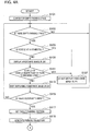
- the process proceeds to step S103, at which if the sensor-information processing unit 104 detects an empty parking space around the host vehicle 22 (Yes at step S103), the process proceeds to step S105.
- step S103 if the sensor-information processing unit 104 does not detect an empty parking space around the host vehicle 22 (No at step S103), the process keeps waiting.
- step S105 the speed determination unit 106 determines whether the speed of the host vehicle 22 is 0 km/h in order to determine whether the host vehicle 22 is at a standstill. If the speed determination unit 106 determines that the host vehicle 22 is not at a standstill (No at step S105), the process proceeds to step S107, and accordingly the image composition unit 1023 does not superimpose the assistance image 24 or the assistance image 25 at the empty parking space 23. The reason is that positional deviation may occur between the position of the empty parking space 23 and the position of the assistance image 24 or the assistance image 25 in the case where the image composition unit 1023 displays the assistance image 24 or the assistance image 25 at the empty parking space 23 while the host vehicle 22 is traveling.
- step S105 determines that the host vehicle 22 is at a standstill (Yes at step S105)
- the process proceeds to step S109, where the image composition unit 1023 displays the assistance image 24 or the assistance image 25 at the empty parking space 23, as illustrated in Fig. 3B . Since the host vehicle 22 is at a standstill, a time lag does not occur, and thus, positional deviation does not occur between the position of the parking space 23 and the position of the assistance image 24 or the assistance image 25. This allows the image composition unit 1023 to superimpose the assistance image 24 or the assistance image 25 at an appropriate position.
- step Sill the speed determination unit 106 determines whether the speed of the host vehicle 22 is higher than or equal to a specified speed. If the speed of the host vehicle 22 is lower than the specified speed (No at step S111), the process proceeds to step S113, where the image composition unit 1023 keeps displaying the assistance image 24 or the assistance image 25. This is because the image composition unit 1023 can track the empty parking space 23 accurately until the speed of the host vehicle 22 becomes higher than or equal to the specified speed, which suppresses positional deviation between the positions of the parking space 23 and the position of the assistance image 24 or the assistance image 25.
- step S111 if the speed of the host vehicle 22 is higher than or equal to the specified speed (Yes at step S111), the process proceeds to step S107, where the image composition unit 1023 does not display the assistance image 24 or the assistance image 25 at the empty parking space.
- errors are accumulated, such as measurement errors of the wheel speed sensor 6, self-position estimation errors of the odometry, errors in detecting the empty parking space 23, so that positional deviation may occur between the position of the parking space 23 and the position of the assistance image 24 or the assistance image 25.
- step S115 if the occupant selects a desired empty parking space via the input interface 8 (Yes at step S115), the process proceeds to step S117. On the other hand, if there is no input from the occupant, the process returns to step S103.
- the target-parking-spot setting unit 1051 sets the target parking position to the empty parking space selected by the occupant.
- the parking-start-position setting unit 1052 determines the parking method and sets a parking start position suitable for the determined parking method. Note that in this flowchart, description is made assuming that the parking method is reverse parking.
- the process proceeds to step S119, where the parking-trajectory generation unit 1054 generates a parking trajectory from the parking start position set at step S117 to the target parking position.
- the process proceeds to step S121, where the vehicle control ECU10 starts the automatic parking control.
- step S123 the self-position estimation unit 1053 determines whether the host vehicle 22 has reached the position at which the shift position is to be switched. If the host vehicle 22 has reached the position at which the shift position is to be switched (Yes at step S123), the process proceeds to step S125, where the vehicle control ECU10 performs shift switching control. After that, the vehicle control ECU10 continues the automatic parking control, and the process proceeds to step S127. On the other hand, if the host vehicle 22 has not reached the position at which the shift position is to be switched (No at step S123), the process keeps waiting.
- step S127 the self-position estimation unit 1053 determines whether the host vehicle 22 has reached the target parking position. If the host vehicle 22 has reached the target parking position (Yes at step S127), the process proceeds to step S129, where the vehicle control ECU10 performs control such as changing the shift position to the parking position, and then the automatic parking control ends.
- the parking assistance device provides the following operational advantages.
- the speed determination unit 106 determines whether the host vehicle 22 is at a standstill. If the speed determination unit 106 determines that the host vehicle 22 is at a standstill, the image composition unit 1023 displays the assistance image 24 or the assistance image 25,indicating that the parking space is empty, at the position of the empty parking space 23 in the surrounding image 20, as illustrated in Fig. 3B . Then, the image composition unit 1023 displays the composed image on the display 9. When the host vehicle 22 is at a standstill, no time lag occurs, and thus, no positional deviation occurs between the position of the parking space 23 and the position of the assistance image 24 or the assistance image 25. In this way, the parking assistance device can display the assistance image 24 or the assistance image 25 at an appropriate position.
- the speed determination unit 106 determines that the host vehicle 22 is at a standstill. The determination in this way allows the speed determination unit 106 to determine swiftly that the host vehicle 22 is at a standstill.
- the image composition unit 1023 After the image composition unit 1023 displays the assistance image 24 or the assistance image 25, the image composition unit 1023 keeps displaying the assistance image 24 or the assistance image 25 until the speed of the host vehicle 22 becomes higher than or equal to a specified speed. This is because the image composition unit 1023 can track the empty parking space 23 accurately until the speed of the host vehicle 22 becomes higher than or equal to the specified speed, which prevents positional deviation between the position of the parking space 23 and the position of the assistance image 24 or the assistance image 25.
- the image composition unit 1023 displays the assistance image 24 or the assistance image 25, in the case where the speed of the host vehicle 22 becomes higher than or equal to the specified speed, the image composition unit 1023 prohibits the assistance image 24 or the assistance image 25 from being displayed. This is because when the speed of the host vehicle 22 is higher than or equal to the specified speed, errors are accumulated, such as measurement errors of the wheel speed sensor 6, self-position estimation errors of the odometry, and errors in detecting the empty parking space 23, so that positional deviation may occur between the position of the parking space 23 and the position of the assistance image 24 or the assistance image 25. Since the image composition unit 1023 prohibits the assistance image 24 or the assistance image 25 from being displayed, it is possible to prevent providing uncertain information to the occupant.
- the image composition unit 1023 displays the assistance image 26 at a fixed position different from the position of the empty parking space 23 as illustrated in Fig. 3A . This allows the occupant to easily understand that there is an empty parking spaces 23.
- the image composition unit 1023 switches the display from the assistance image 26 to the assistance image 24 or the assistance image 25 as illustrated in Fig. 3B . This allows the occupant to easily understand the position of the empty parking space 23.
- the image composition unit 1023 prohibits the assistance image 24 or the assistance image 25 from being displayed. This is because positional deviation may occur between the position of the empty parking space 23 and the position of the assistance image 24 or the assistance image 25 in the case where the image composition unit 1023 displays the assistance image 24 or the assistance image 25 at the empty parking space 23 while the host vehicle 22 is traveling. Since the image composition unit 1023 prohibits the assistance image 24 or the assistance image 25 from being displayed, it is possible to prevent providing uncertain information to the occupant.
- the assistance image 26 illustrated in Fig. 3A is represented in a quadrangle shape, and the assistance image 24 and the assistance image 25 illustrated in Fig. 3B are each represented in a round shape, the shapes are not limited to these examples.
- the assistance image 26, the assistance image 24, and the assistance image 25 may have any shape that can be distinguished one from the others.
- the speed determination unit 106 determines that the host vehicle 22 is at a standstill in the case where the speed of the host vehicle 22 is 0 km/h
- the present invention is not limited to this operation. It is not always true that when the speed of the host vehicle 22 is 0 km/h, the host vehicle 22 is at a standstill. For example, even when the occupant steps on the brake pedal, and the speed of the host vehicle 22 has become 0 km/h, there is a possibility that the host vehicle 22 may be slipping when the ground is wet or when the tires are worn. In other words, even when the speed meter indicates 0 km/h, the speed detected by the wheel speed sensor 6 is not always 0 km/h.
- the speed determination unit 106 may set a margin and determine that the host vehicle 22 has stopped when the speed of the host vehicle 22 is lower than or equal to a specified speed. The determination in this way allows the speed determination unit 106 to determine in various road environments whether the host vehicle 22 is at a standstill.
- the speed determination unit 106 may determine whether the parking brake of the host vehicle 22 is applied and may determine that the host vehicle 22 is at a standstill when the parking brake is applied. The determination in this way allows the speed determination unit 106 to determine in various road environments whether the host vehicle 22 is at a standstill.
- the parking brake referred to above includes a hand brake and a foot brake.
- the speed determination unit 106 may determine whether the shift lever of the host vehicle 22 is at the park position and determine that the host vehicle 22 is at a standstill when the shift lever is at the park position. The determination in this way allows the speed determination unit 106 to determine in various road environments whether the host vehicle 22 is at a standstill. Although in this example, it is determined whether the shift lever is at the park position, it may be determined in this determination that the shift lever is at the park position in the case where the parking button for moving into the parking mode is pressed and the vehicle has been put into the parking mode.
- the speed determination unit 106 may determine whether the speed of the host vehicle is lower than or equal to a specified speed (for example, 5 km or less) set in advance and may determine that the host vehicle is at a standstill when it is determined that the vehicle speed is lower than or equal to the specified speed. The determination in this way allows the speed determination unit 106 to display the first assistance image when the speed becomes lower than or equal to the specified speed even before the host vehicle stops. Thus, it is possible to display the first assistance image for the occupant at an appropriate timing.
- a specified speed for example, 5 km or less
- the speed determination unit 106 may determine whether the speed of the host vehicle is lower than or equal to a specified speed (for example, 5 km or less) set in advance and, in the case where it is determined that the vehicle speed is lower than or equal to the specified speed, may determine whether deceleration operation is being performed in the host vehicle. In the case where it is determined that deceleration operation is being performed, the speed determination unit 106 may estimate that the host vehicle is stopping and determine that the host vehicle has stopped. The determination in this way allows the speed determination unit 106 to display the first assistance image in the case where deceleration operation is performed at a speed lower than or equal to the specified speed even before the host vehicle stops. Thus, it is possible to display the first assistance image for the occupant at an appropriate timing.
- the deceleration operation in the present embodiment means the state where the brake actuator is operating and thus includes not only operation of the brake actuator by the occupant but also the case where the brake actuator is operating without the occupant' operation.
- the driving mode at the time when the sensor-information processing unit 104 detects an empty parking space may be either manual driving by the occupant or automated driving.
Landscapes
- Engineering & Computer Science (AREA)
- Mechanical Engineering (AREA)
- Transportation (AREA)
- Physics & Mathematics (AREA)
- Multimedia (AREA)
- General Physics & Mathematics (AREA)
- Automation & Control Theory (AREA)
- Combustion & Propulsion (AREA)
- Chemical & Material Sciences (AREA)
- Mathematical Physics (AREA)
- Human Computer Interaction (AREA)
- Theoretical Computer Science (AREA)
- Signal Processing (AREA)
- Traffic Control Systems (AREA)
- Closed-Circuit Television Systems (AREA)
- Image Processing (AREA)
Abstract
Description
- The present invention relates to parking assistance methods and parking assistance devices.
- There have been known inventions for assisting parking operation of the occupant (Patent Literature 1). In the invention disclosed in
Patent Literature 1, an empty parking space is searched for while the vehicle is traveling. In the case where an empty parking space is detected, an image indicating the empty parking space is displayed on a display. - Patent Literature 1: Japanese Patent Application Publication No.
2008-96362 - Unfortunately, in the case where an image indicating an empty parking space is displayed while the vehicle is travelling, as in the invention disclosed in
Patent Literature 1, the image may not be displayed at an appropriate position because of processing delay or other factors. - The present invention has been made in light of the above problem, and an object thereof is to provide a parking assistance method and parking assistance device capable of displaying an image indicating an empty parking space, at an appropriate position.
- A parking assistance method according to an aspect of the present invention includes: determining whether a host vehicle has stopped; and in a case where it is determined that the host vehicle has stopped, displaying an image at a position of an empty parking space in a surrounding image that is a view of an area including the host vehicle from above, the image indicating the empty parking space.
- The present invention makes it possible to display an image indicating an empty parking space, at an appropriate position.
-
- [
Fig. 1] Fig. 1 is an overall configuration diagram a parking assistance device according to an embodiment of the present invention. - [
Fig. 2] Fig. 2 is a configuration diagram of part of the parking assistance device according to the embodiment of the present invention. - [
Fig. 3A] Fig. 3A is a diagram for explaining an operation example of the parking assistance device according to the embodiment of the present invention. - [
Fig. 3B] Fig. 3B is a diagram for explaining another operation example of the parking assistance device according to the embodiment of the present invention. - [
Fig. 4A] Fig. 4A is a flowchart for explaining an operation example of the parking assistance device according to the embodiment of the present invention. - [
Fig. 4B] Fig. 4B is a flowchart for explaining an operation example of the parking assistance device according to the embodiment of the present invention. - Hereinafter, an embodiment of the present invention will be described with reference to the drawings. The same constituents in the drawings are denoted by the same symbols, and description thereof is omitted. A parking assistance device according to the present embodiment is applied to a vehicle in which its driving mode can be switched between automated driving and manual driving. Note that automated driving in the present embodiment means, for example, the state where at least one of the actuators including the brakes, accelerator, and steering is being controlled without operation by the occupant. It means that the other actuators may be being operated by the occupant. The automated driving also means the state where at least one kind of control such as acceleration-deceleration control or lateral position control is being executed. Manual driving in the present embodiment means, for example, the state where the occupant is operating the brakes, accelerator, and steering. Note that the embodiment of the present invention can be applied to both automated driving and manual driving. In addition, the embodiment of the present invention can be applied to any case of traveling in a parking lot having parking spaces, including when detecting an empty parking space, when having detected an empty parking space, when parking in (moving to) an empty parking space, when traveling near an empty parking space, and when traveling in a parking lot although there is no empty parking space.
- The configuration of a parking assistance device according to the present embodiment will be described with reference to
Fig. 1 . The parking assistance device includes acontroller 1,cameras 2a to 2d, asteering angle sensor 3, awheel speed sensor 6, a spatial recognition sensor 7, aninput interface 8, adisplay 9, a vehicle control ECU10, and anactuator 11. - The
cameras 2a to 2d each have an image capturing device, such as a charge-coupled device (CCD) or a complementary metal oxide semiconductor (CMOS) and capture images around the host vehicle. Thecamera 2a is mounted at a front portion of the host vehicle to capture images ahead of the host vehicle. Thecamera 2b is mounted at a rear portion of the host vehicle to capture images behind the host vehicle. Thecamera 2c is mounted at a left side of the host vehicle to capture images on the left side of the host vehicle. Thecamera 2d is mounted at a right side of the host vehicle to capture images on the right side of the host vehicle. Thecameras 2a to 2d output captured images to thecontroller 1. Note that thecameras 2a to 2d capture images of the surroundings of the host vehicle and do not capture the host vehicle itself. Hence, when animage composition unit 1023 described later displays a downward view image, theimage composition unit 1023 uses an icon (an image imitating the host vehicle) stored in anicon storing unit 103. - The
steering angle sensor 3 detects the steering angle of the host vehicle and outputs the detected steering angle to thecontroller 1. Thewheel speed sensor 6 detects the speed of the host vehicle and outputs the detected speed to aspeed determination unit 106. - The spatial recognition sensor 7 is a sensor for detecting objects around the host vehicle, which is, for example, a laser range finder. The laser range finder projects infrared laser light toward a target object and measures the distance to the target object using the intensity of the reflected light. The laser range finder obtains the measured distance as point cloud information and outputs the point cloud information to a sensor-
information processing unit 104. Objects around the host vehicle mean moving objects including other vehicles, motorbikes, bicycles, and pedestrians and stationary objects including parked vehicles. Note that the spatial recognition sensor 7 is not limited to a laser range finder. The spatial recognition sensor 7 only needs to detect the distance to a target object and the presence of the target object, and hence the spatial recognition sensor 7 may be, for example, a clearance sonar utilizing ultrasonic, a monocular camera, or a stereo camera having a pair of cameras. - The
input interface 8 is a device that receives input from the occupant of the host vehicle. Theinput interface 8 is, for example, a touch panel provided on thedisplay 9. Note that theinput interface 8 may be a joystick or an operation switch or may be a voice input device. - The
controller 1 is circuitry that processes data obtained from various sensors and is, for example, a general-purpose microcomputer including a central processing unit (CPU), memory, and an input-output unit. A computer program that causes the microcomputer to function as thecontroller 1 is installed in and executed by the microcomputer. This makes the microcomputer function as thecontroller 1. Note that although here, description is made of an example in which thecontroller 1 is implemented by software, dedicated hardware for executing information processes described below, as a matter of course, may be used to configure thecontroller 1. Thecontroller 1 includes multiple information process circuits, which are a surrounding-image generation unit 101, a composite-image generation unit 102, theicon storing unit 103, the sensor-information processing unit 104, a parking-assistance calculation unit 105, and thespeed determination unit 106. The composite-image generation unit 102 includes an assistance-image generation unit 1021, a display-switchingcontrol unit 1022, and theimage composition unit 1023. - The surrounding-image generation unit 101 (surrounding-image generation circuit) generates a downward view image (surrounding image) which is a view of the host vehicle from above, using images captured by the four
cameras 2a to 2d. Note that the surrounding image may be any form from which the positional relationship between the host vehicle and the parking spaces can be seen, such as a downward view image and a bird's view image. In addition, since how to generate the downward view image or the bird's view image is a known technique, detailed description thereof is omitted. - The sensor-information processing unit 104 (sensor-information processing circuit) estimates a travel path along which the host vehicle is to travel, using information obtained from the spatial recognition sensor 7. The sensor-
information processing unit 104 estimates a parking area (parking spot) in the vicinities of the estimated travel path. The sensor-information processing unit 104 detects empty parking spaces around the host vehicle. The sensor-information processing unit 104 estimates the range in which the host vehicle can travel based on the estimated travel path and parking spots. The sensor-information processing unit 104 may detect parking spots using white lines on the ground. - The speed determination unit 106 (stop determination circuit) determines the speed of the host vehicle, using the speed obtained from the
wheel speed sensor 6. Thespeed determination unit 106 outputs the determination result to the display-switchingcontrol unit 1022. - The assistance-
image generation unit 1021 generates assistance images for assisting parking. Note that the assistance images may be stored in theicon storing unit 103 in advance. In the case where the assistance images are stored in theicon storing unit 103, the assistance-image generation unit 1021 can read the assistance images from theicon storing unit 103. The assistance-image generation unit 1021 outputs the generated assistance images to the display-switchingcontrol unit 1022. - The display-switching
control unit 1022 determines whether to output assistance images obtained from the assistance-image generation unit 1021 to theimage composition unit 1023, depending on the determination result by thespeed determination unit 106. For example, in the case where the speed of the host vehicle is 0 km/h, the display-switchingcontrol unit 1022 outputs an assistance image to theimage composition unit 1023. Details will be described later. - The image composition unit 1023 (image display circuit) superimposes the icon (the image imitating the host vehicle) obtained from the
icon storing unit 103 on the surrounding image generated by the surrounding-image generation unit 101 to make a composite image. In the case where theimage composition unit 1023 obtains the assistance image from the display-switchingcontrol unit 1022, theimage composition unit 1023 superimposes the assistance image on the surrounding image. Theimage composition unit 1023 outputs the composed image to thedisplay 9. - The parking-
assistance calculation unit 105 calculates a control signal for the host vehicle based on information inputted to theinput interface 8, data obtained by the sensor-information processing unit 104, the steering angle detected by thesteering angle sensor 3, and the vehicle speed detected by thewheel speed sensor 6. The parking-assistance calculation unit 105 outputs the calculated control signal to the vehicle control ECU10. - The vehicle control ECU10 automatically controls driving of the
actuator 11 on driving, braking, and steering the host vehicle, based on the control signal and the like obtained from the parking-assistance calculation unit 105. - The
display 9 is a device for displaying various kinds of information for the occupant, which is, for example, a display for navigation provided in the passenger compartment. - Next, the parking-
assistance calculation unit 105 will be described in detail with reference toFig. 2 . As illustrated inFig. 2 , the parking-assistance calculation unit 105 includes a target-parking-spot setting unit 1051, parking-start-position setting unit 1052, self-position estimation unit 1053, parking-trajectory generation unit 1054, parking-trajectory tracking-control unit 1055, and target-speed generation unit 1056. - The target-parking-
spot setting unit 1051 sets the target parking position to a parking position that the occupant input to theinput interface 8. The target-parking-spot setting unit 1051 outputs the set target parking position to the parking-start-position setting unit 1052 and the parking-trajectory generation unit 1054. - The parking-start-
position setting unit 1052 determines a parking method suitable for parking at the target parking position and sets a parking start position suitable for the determined parking method. Examples of the parking method include parallel parking and perpendicular parking, and reverse parking and forward parking. The parking-start-position setting unit 1052 outputs the set parking start position to the parking-trajectory generation unit 1054. - The self-
position estimation unit 1053 estimates the current position of the host vehicle, based on detection data and the like of thewheel speed sensor 6 andsteering angle sensor 3. For a front-wheel-steering vehicle traveling at a low speed, it is common to use a dead reckoning approach in which the position and orientation of the host vehicle are estimated based on the relationship between the travel distance of the center of the rear wheel axle and the front-wheel steering angle. The dead reckoning approach is useful for the case of considering traveling in a limited section such as parking operation. As another example, the self-position estimation unit 1053 can also estimate the self-position based on the positional relationship of the host vehicle relative to detection data detected by the spatial recognition sensor 7, the positional relationship of the host vehicle relative to white lines on the ground captured by thecameras 2a to 2d and object recognition results, or the like. Alternatively, the self-position estimation unit 1053 may estimate the absolute position of the host vehicle, in other words, the position of the host vehicle relative to a specified reference point, using a position detection sensor. The position detection sensor is a device mounted on the host vehicle for measuring the absolute position of the host vehicle using a global positioning system (GPS), odometry, or the like. The self-position estimation unit 1053 outputs the estimated self-position to the parking-trajectory tracking-control unit 1055. - The parking-
trajectory generation unit 1054 generates a parking trajectory from the parking start position set by the parking-start-position setting unit 1052 to the target parking position. The parking-trajectory generation unit 1054 generates a parking trajectory, for example, such that the number of forward and backward movements and the amount of steering are minimized, so that the occupant does not feel discomfort. The parking-trajectory generation unit 1054 outputs the generated parking trajectory to the parking-trajectory tracking-control unit 1055 and the target-speed generation unit 1056. - The parking-trajectory tracking-
control unit 1055 generates a control signal for performing automatic parking control along the parking trajectory, based on the parking trajectory generated by the parking-trajectory generation unit 1054 and the self-position estimated by the self-position estimation unit 1053. For example, the parking-trajectory tracking-control unit 1055 generates a control signal related to the steering angle and the shift position. The parking-trajectory tracking-control unit 1055 outputs the generated control signal to the vehicle control ECU10. - The target-
speed generation unit 1056 generates a control signal for performing automatic parking control along the parking trajectory generated by the parking-trajectory generation unit 1054. For example, the target-speed generation unit 1056 generates a control signal related to the speed (the amount of acceleration and the amount of braking). The target-speed generation unit 1056 outputs the generated control signal to the vehicle control ECU10. - The vehicle control ECU10 controls the
actuator 11 based on the control signals generated by the parking-trajectory tracking-control unit 1055 and the target-speed generation unit 1056 to achieve automatic parking control. - Next, an operation example of a parking assistance device will be described with reference to surrounding
images 20 illustrated inFigs. 3A and 3B . - The scene illustrated in
Fig. 3A is a scene in which thehost vehicle 22 is traveling in a parking lot while detecting an empty parking space. In the scene illustrated inFig. 3A , it is assumed that the speed of thehost vehicle 22 is more than 0 km/h. The scene illustrated inFig. 3B is also a scene of detecting an empty parking space, and in the scene illustrated inFig. 3B , it is assumed that the speed of thehost vehicle 22 is 0 km/h. - In the case where the sensor-
information processing unit 104 detectsempty parking spaces 23 as a result of detecting empty parking spaces around thehost vehicle 22 as illustrated inFig. 3A , thespeed determination unit 106 determines whether thehost vehicle 22 is traveling. Specifically, in the case where thespeed determination unit 106 determines whether the speed of thehost vehicle 22 is more than 0 km/h and determines that the speed of thehost vehicle 22 is more than 0 km/h, thespeed determination unit 106 determines that thehost vehicle 22 is traveling. - In the case where the
speed determination unit 106 determines that thehost vehicle 22 is traveling, theimage composition unit 1023 superimposes an assistance image 26 (the second assistance image) on the surroundingimage 20 as illustrated inFig. 3A . Then, theimage composition unit 1023 displays the composite image with theassistance image 26 superimposed, on thedisplay 9. Theassistance image 26 is an image indicating anempty parking space 23 is detected around thehost vehicle 22. Theassistance image 26 is not an image showing theempty parking space 23 itself. Hence, theassistance image 26 is superimposed at a fixed position different from the position of theempty parking space 23. For example, in the present embodiment, theassistance image 26 is superimposed at an upper center of the surroundingimage 20. - Since the
assistance image 26 is displayed at a position different from theempty parking space 23 as described above while thehost vehicle 22 is traveling, the occupant can easily understand by seeing theassistance image 26 that there areempty parking spaces 23. This allows the occupant to take actions to park in anempty parking space 23. - Next, with reference to
Fig. 3B , description will be made for the case where the speed of thehost vehicle 22 is 0 km/h. In the case where the sensor-information processing unit 104 detectsempty parking spaces 23 around thehost vehicle 22 as illustrated inFig. 3B , thespeed determination unit 106 determines whether thehost vehicle 22 is at a standstill. Specifically, thespeed determination unit 106 determines whether the speed of thehost vehicle 22 is 0 km/h. If the speed of thehost vehicle 22 is 0 km/h, thespeed determination unit 106 determines that thehost vehicle 22 is at a standstill. - In the case where the
speed determination unit 106 determines that thehost vehicle 22 is at a standstill as illustrated inFig. 3B , theimage composition unit 1023 superimposes anassistance image 24 or assistance image 25 (a first assistance image) on eachempty parking space 23. Theassistance image 24 and theassistance image 25 are images indicating that the parking space is empty. Note that theassistance image 25 shows that the parking space is empty and that this place is a recommended parking space. The recommended parking space means, for example, a space that is easy to park in. The recommended parking space may be a space that requires a shorter time to park there or may be a space the parking trajectory to which is short. In addition, the recommended parking space may also be a space the parking trajectory to which includes no sharp turn, a space into which reverse parking is possible, or a space that is easy to exit from. Theassistance image 24 only indicates that the parking space is empty. - Since the
assistance image 24 or theassistance image 25 is displayed at an appropriate position at theempty parking space 23 as described above while thehost vehicle 22 is at a standstill, the occupant can easily understand that theempty parking spaces 23 are empty. This allows the occupant to take actions to park in a desired empty parking space. In addition, for example, in the case where automatic parking control is available as in the present embodiment, the occupant's touch on the assistance image 25 (recommended parking space) initiates parking control to the target parking position automatically. - Note that as illustrated in
Fig. 3B , in the case where thehost vehicle 22 is at a standstill, theimage composition unit 1023 does not superimpose theassistance image 26 illustrated inFig. 3A . This is because when thehost vehicle 22 is at a standstill, theimage composition unit 1023 superimposes theassistance images 24 and theassistance image 25 on theempty parking spaces 23, so that the occupant can easily understand that there areempty parking spaces 23, without anassistance image 26 superimposed. Note that it was stated that when thehost vehicle 22 is at a standstill, theimage composition unit 1023 does not superimpose theassistance image 26, but the present invention is not limited to this example. For example, theimage composition unit 1023 may superimpose theassistance image 26, for example, with its color made fainter (by adjusting its transparency) or with its color changed (for example, from blue to gray). - Meanwhile, as illustrated in
Fig. 3A , when thehost vehicle 22 is traveling, theimage composition unit 1023 does not superimpose theassistance image 24 or theassistance image 25 illustrated inFig. 3B on the surroundingimage 20. In other words, when thehost vehicle 22 is traveling, theimage composition unit 1023 prohibits theassistance image 24 or theassistance image 25 from being superimposed. The reason will be explained below. - First of all, description will be made of the order in which the
image composition unit 1023 superimposes theassistance image 24 or theassistance image 25 on anempty parking space 23. First, theimage composition unit 1023 recognizesempty parking spaces 23 in the surroundingimage 20. Next, theimage composition unit 1023 superimposes theassistance images 24 and theassistance image 25 on the recognizedempty parking spaces 23. If thehost vehicle 22 moves while theimage composition unit 1023 is performing such processes, theempty parking spaces 23 in the surroundingimage 20 that theimage composition unit 1023 has recognized also move. Specifically, theimage composition unit 1023 recognizes theempty parking spaces 23, and at the next moment when theimage composition unit 1023 is about to superimpose theassistance images 24 and theassistance image 25 on the recognizedempty parking spaces 23, theempty parking spaces 23 have already moved from the positions when they were recognized. As above, a time lag occurs between the time when theimage composition unit 1023 recognizes theempty parking spaces 23 and the time when theimage composition unit 1023 superimposes theassistance images 24 and theassistance image 25 on the recognizedempty parking spaces 23. This time lag may cause positional deviation between the positions of theempty parking spaces 23 and the positions of theassistance images 24 and theassistance image 25. Specifically, in the case where theimage composition unit 1023 superimposes theassistance images 24 and theassistance image 25 on theempty parking spaces 23 in the surroundingimage 20 while thehost vehicle 22 is traveling, it is possible that theassistance images 24 and theassistance image 25 cannot be superimposed at appropriate positions. Note that such positional deviation becomes larger as the speed of thehost vehicle 22 increases. - In light of the above, in the present embodiment, when the
host vehicle 22 is traveling, theimage composition unit 1023 does not display theassistance image 24 or theassistance image 25 at theempty parking spaces 23. This prevents positional deviation between the positions of theempty parking spaces 23 and the positions of theassistance images 24 and theassistance image 25. Thus, the parking assistance device prevents providing uncertain information to the occupant. Note that when thehost vehicle 22 is traveling, theimage composition unit 1023 superimposes theassistance image 26 at a position different from theempty parking spaces 23, instead of displaying theassistance images 24 and theassistance image 25 at theempty parking spaces 23 as illustrated inFig. 3A . This allows the occupant to understand that there areempty parking spaces 23 by seeing theassistance image 26. Since theassistance image 26 is displayed at a position different from theempty parking spaces 23, theimage composition unit 1023 does not need to take the foregoing time lag into an account. - When the
host vehicle 22 is at a standstill, theimage composition unit 1023 displays theassistance images 24 and theassistance image 25 at theempty parking spaces 23 as illustrated inFig. 3B . Since thehost vehicle 22 is at a standstill, the foregoing time lag does not occur, and thus, positional deviation does not occur between the positions of theparking spaces 23 and the positions of theassistance images 24 and theassistance image 25. Since theimage composition unit 1023 displays theassistance images 24 and theassistance image 25 at theempty parking space 23 when thehost vehicle 22 is at a standstill, theimage composition unit 1023 can display theassistance images 24 and the assistance image 25at appropriate positions. - After the
image composition unit 1023 displays theassistance images 24 and theassistance image 25 at the positions of theempty parking spaces 23, theimage composition unit 1023 keeps displaying theassistance images 24 and theassistance image 25 until the speed of thehost vehicle 22 becomes higher than or equal to a specified speed. Thus, the occupant can select a desired empty parking space until the speed of thehost vehicle 22 becomes higher than or equal to a specified speed. - The reason why the
image composition unit 1023 keeps displaying theassistance images 24 and theassistance image 25 until the speed of thehost vehicle 22 becomes higher than or equal to a specified speed is that positional deviation between the positions of theempty parking spaces 23 and the positions of theassistance images 24 and theassistance image 25 is suppressed until the speed of thehost vehicle 22 becomes higher than or equal to the specified speed. In other words, until the speed of thehost vehicle 22 becomes higher than or equal to the specified speed, theimage composition unit 1023 can track theempty parking spaces 23 accurately. - The
image composition unit 1023 can track position data indicating theempty parking spaces 23 as time series data. The position data indicating theempty parking spaces 23 is stored on a map. When thehost vehicle 22 is at a standstill, theimage composition unit 1023 can obtain the position data indicating theempty parking spaces 23 accurately, compared to the time when thehost vehicle 22 is traveling. Thus, theimage composition unit 1023 can accurately display theassistance images 24 and theassistance image 25, having the positional relationship relative to the positions indicating theempty parking spaces 23, at theempty parking spaces 23. After that, when thehost vehicle 22 starts moving from its standstill state, theimage composition unit 1023 can track theempty parking spaces 23 accurately by moving thehost vehicle 22 on the map according to the movement of thehost vehicle 22. Thus, theimage composition unit 1023 can display theassistance images 24 and theassistance image 25 accurately at theempty parking spaces 23. However, in the case where errors are accumulated, such as measurement errors of thewheel speed sensor 6, self-position estimation errors of the odometry, and errors in detecting theempty parking spaces 23, the foregoing positional deviation may occur. Hence, when the speed of thehost vehicle 22 is higher than or equal to a specified speed, theimage composition unit 1023 does not display theassistance image 24 or theassistance image 25. Thus, theimage composition unit 1023 prevents providing uncertain information to the occupant. Note that the foregoing map data may be stored in advance in the parking assistance device or may be obtained from an external map data server through cloud computing. Alternatively, theimage composition unit 1023 may obtain map data through inter-vehicle communication or road-vehicle communication. Note that although the specified speed is not limited to any specific speed, it can be, for example, 3 km/h to 5 km/h. - Next, an operation example will be described with reference to the flowchart in
Fig. 4 . - At step S101, the sensor-
information processing unit 104 detects empty parking spaces based on information obtained from the spatial recognition sensor 7. The process proceeds to step S103, at which if the sensor-information processing unit 104 detects an empty parking space around the host vehicle 22 (Yes at step S103), the process proceeds to step S105. At step S103, if the sensor-information processing unit 104 does not detect an empty parking space around the host vehicle 22 (No at step S103), the process keeps waiting. - At step S105 the
speed determination unit 106 determines whether the speed of thehost vehicle 22 is 0 km/h in order to determine whether thehost vehicle 22 is at a standstill. If thespeed determination unit 106 determines that thehost vehicle 22 is not at a standstill (No at step S105), the process proceeds to step S107, and accordingly theimage composition unit 1023 does not superimpose theassistance image 24 or theassistance image 25 at theempty parking space 23. The reason is that positional deviation may occur between the position of theempty parking space 23 and the position of theassistance image 24 or theassistance image 25 in the case where theimage composition unit 1023 displays theassistance image 24 or theassistance image 25 at theempty parking space 23 while thehost vehicle 22 is traveling. - On the other hand, if the
speed determination unit 106 determines that thehost vehicle 22 is at a standstill (Yes at step S105), the process proceeds to step S109, where theimage composition unit 1023 displays theassistance image 24 or theassistance image 25 at theempty parking space 23, as illustrated inFig. 3B . Since thehost vehicle 22 is at a standstill, a time lag does not occur, and thus, positional deviation does not occur between the position of theparking space 23 and the position of theassistance image 24 or theassistance image 25. This allows theimage composition unit 1023 to superimpose theassistance image 24 or theassistance image 25 at an appropriate position. - The process proceeds to step Sill, where the
speed determination unit 106 determines whether the speed of thehost vehicle 22 is higher than or equal to a specified speed. If the speed of thehost vehicle 22 is lower than the specified speed (No at step S111), the process proceeds to step S113, where theimage composition unit 1023 keeps displaying theassistance image 24 or theassistance image 25. This is because theimage composition unit 1023 can track theempty parking space 23 accurately until the speed of thehost vehicle 22 becomes higher than or equal to the specified speed, which suppresses positional deviation between the positions of theparking space 23 and the position of theassistance image 24 or theassistance image 25. On the other hand, if the speed of thehost vehicle 22 is higher than or equal to the specified speed (Yes at step S111), the process proceeds to step S107, where theimage composition unit 1023 does not display theassistance image 24 or theassistance image 25 at the empty parking space. This is because when the speed of thehost vehicle 22 is higher than or equal to the specified speed, errors are accumulated, such as measurement errors of thewheel speed sensor 6, self-position estimation errors of the odometry, errors in detecting theempty parking space 23, so that positional deviation may occur between the position of theparking space 23 and the position of theassistance image 24 or theassistance image 25. - The process proceeds to step S115, where if the occupant selects a desired empty parking space via the input interface 8 (Yes at step S115), the process proceeds to step S117. On the other hand, if there is no input from the occupant, the process returns to step S103.
- At step S117, the target-parking-
spot setting unit 1051 sets the target parking position to the empty parking space selected by the occupant. The parking-start-position setting unit 1052 determines the parking method and sets a parking start position suitable for the determined parking method. Note that in this flowchart, description is made assuming that the parking method is reverse parking. After that, the process proceeds to step S119, where the parking-trajectory generation unit 1054 generates a parking trajectory from the parking start position set at step S117 to the target parking position. Next, the process proceeds to step S121, where the vehicle control ECU10 starts the automatic parking control. - Next, the process proceeds to step S123, where the self-
position estimation unit 1053 determines whether thehost vehicle 22 has reached the position at which the shift position is to be switched. If thehost vehicle 22 has reached the position at which the shift position is to be switched (Yes at step S123), the process proceeds to step S125, where the vehicle control ECU10 performs shift switching control. After that, the vehicle control ECU10 continues the automatic parking control, and the process proceeds to step S127. On the other hand, if thehost vehicle 22 has not reached the position at which the shift position is to be switched (No at step S123), the process keeps waiting. At step S127, the self-position estimation unit 1053 determines whether thehost vehicle 22 has reached the target parking position. If thehost vehicle 22 has reached the target parking position (Yes at step S127), the process proceeds to step S129, where the vehicle control ECU10 performs control such as changing the shift position to the parking position, and then the automatic parking control ends. - As has been described above, the parking assistance device according to the present embodiment provides the following operational advantages.
- When the sensor-
information processing unit 104 has detected anempty parking space 23 around thehost vehicle 22, thespeed determination unit 106 determines whether thehost vehicle 22 is at a standstill. If thespeed determination unit 106 determines that thehost vehicle 22 is at a standstill, theimage composition unit 1023 displays theassistance image 24 or theassistance image 25,indicating that the parking space is empty, at the position of theempty parking space 23 in the surroundingimage 20, as illustrated inFig. 3B . Then, theimage composition unit 1023 displays the composed image on thedisplay 9. When thehost vehicle 22 is at a standstill, no time lag occurs, and thus, no positional deviation occurs between the position of theparking space 23 and the position of theassistance image 24 or theassistance image 25. In this way, the parking assistance device can display theassistance image 24 or theassistance image 25 at an appropriate position. - In the case where the speed of the
host vehicle 22 is 0 km/h, thespeed determination unit 106 determines that thehost vehicle 22 is at a standstill. The determination in this way allows thespeed determination unit 106 to determine swiftly that thehost vehicle 22 is at a standstill. - After the
image composition unit 1023 displays theassistance image 24 or theassistance image 25, theimage composition unit 1023 keeps displaying theassistance image 24 or theassistance image 25 until the speed of thehost vehicle 22 becomes higher than or equal to a specified speed. This is because theimage composition unit 1023 can track theempty parking space 23 accurately until the speed of thehost vehicle 22 becomes higher than or equal to the specified speed, which prevents positional deviation between the position of theparking space 23 and the position of theassistance image 24 or theassistance image 25. - After the
image composition unit 1023 displays theassistance image 24 or theassistance image 25, in the case where the speed of thehost vehicle 22 becomes higher than or equal to the specified speed, theimage composition unit 1023 prohibits theassistance image 24 or theassistance image 25 from being displayed. This is because when the speed of thehost vehicle 22 is higher than or equal to the specified speed, errors are accumulated, such as measurement errors of thewheel speed sensor 6, self-position estimation errors of the odometry, and errors in detecting theempty parking space 23, so that positional deviation may occur between the position of theparking space 23 and the position of theassistance image 24 or theassistance image 25. Since theimage composition unit 1023 prohibits theassistance image 24 or theassistance image 25 from being displayed, it is possible to prevent providing uncertain information to the occupant. - When the
host vehicle 22 is not at a standstill, in other words, when thehost vehicle 22 is traveling, theimage composition unit 1023 displays theassistance image 26 at a fixed position different from the position of theempty parking space 23 as illustrated inFig. 3A . This allows the occupant to easily understand that there is anempty parking spaces 23. - In the case where the
host vehicle 22 stops while theassistance image 26 is displayed as illustrated inFig. 3A , theimage composition unit 1023 switches the display from theassistance image 26 to theassistance image 24 or theassistance image 25 as illustrated inFig. 3B . This allows the occupant to easily understand the position of theempty parking space 23. - When the
host vehicle 22 is not at a standstill, theimage composition unit 1023 prohibits theassistance image 24 or theassistance image 25 from being displayed. This is because positional deviation may occur between the position of theempty parking space 23 and the position of theassistance image 24 or theassistance image 25 in the case where theimage composition unit 1023 displays theassistance image 24 or theassistance image 25 at theempty parking space 23 while thehost vehicle 22 is traveling. Since theimage composition unit 1023 prohibits theassistance image 24 or theassistance image 25 from being displayed, it is possible to prevent providing uncertain information to the occupant. - Although an embodiment of the present invention has been described as above, it should not be understood that the descriptions and drawings constituting part of this disclosure limit this invention. From this disclosure, various alternative embodiments, examples, and operational techniques will be apparent to those skilled in the art.
- Although in the present embodiment, the
assistance image 26 illustrated inFig. 3A is represented in a quadrangle shape, and theassistance image 24 and theassistance image 25 illustrated inFig. 3B are each represented in a round shape, the shapes are not limited to these examples. Theassistance image 26, theassistance image 24, and theassistance image 25 may have any shape that can be distinguished one from the others. - Although in the present embodiment, the
speed determination unit 106 determines that thehost vehicle 22 is at a standstill in the case where the speed of thehost vehicle 22 is 0 km/h, the present invention is not limited to this operation. It is not always true that when the speed of thehost vehicle 22 is 0 km/h, thehost vehicle 22 is at a standstill. For example, even when the occupant steps on the brake pedal, and the speed of thehost vehicle 22 has become 0 km/h, there is a possibility that thehost vehicle 22 may be slipping when the ground is wet or when the tires are worn. In other words, even when the speed meter indicates 0 km/h, the speed detected by thewheel speed sensor 6 is not always 0 km/h. Accordingly, thespeed determination unit 106 may set a margin and determine that thehost vehicle 22 has stopped when the speed of thehost vehicle 22 is lower than or equal to a specified speed. The determination in this way allows thespeed determination unit 106 to determine in various road environments whether thehost vehicle 22 is at a standstill. - Here, the
speed determination unit 106 may determine whether the parking brake of thehost vehicle 22 is applied and may determine that thehost vehicle 22 is at a standstill when the parking brake is applied. The determination in this way allows thespeed determination unit 106 to determine in various road environments whether thehost vehicle 22 is at a standstill. Here, the parking brake referred to above includes a hand brake and a foot brake. - As an alternative, the
speed determination unit 106 may determine whether the shift lever of thehost vehicle 22 is at the park position and determine that thehost vehicle 22 is at a standstill when the shift lever is at the park position. The determination in this way allows thespeed determination unit 106 to determine in various road environments whether thehost vehicle 22 is at a standstill. Although in this example, it is determined whether the shift lever is at the park position, it may be determined in this determination that the shift lever is at the park position in the case where the parking button for moving into the parking mode is pressed and the vehicle has been put into the parking mode. - Alternatively, the
speed determination unit 106 may determine whether the speed of the host vehicle is lower than or equal to a specified speed (for example, 5 km or less) set in advance and may determine that the host vehicle is at a standstill when it is determined that the vehicle speed is lower than or equal to the specified speed. The determination in this way allows thespeed determination unit 106 to display the first assistance image when the speed becomes lower than or equal to the specified speed even before the host vehicle stops. Thus, it is possible to display the first assistance image for the occupant at an appropriate timing. - As an alternative, the
speed determination unit 106 may determine whether the speed of the host vehicle is lower than or equal to a specified speed (for example, 5 km or less) set in advance and, in the case where it is determined that the vehicle speed is lower than or equal to the specified speed, may determine whether deceleration operation is being performed in the host vehicle. In the case where it is determined that deceleration operation is being performed, thespeed determination unit 106 may estimate that the host vehicle is stopping and determine that the host vehicle has stopped. The determination in this way allows thespeed determination unit 106 to display the first assistance image in the case where deceleration operation is performed at a speed lower than or equal to the specified speed even before the host vehicle stops. Thus, it is possible to display the first assistance image for the occupant at an appropriate timing. Note that the deceleration operation in the present embodiment means the state where the brake actuator is operating and thus includes not only operation of the brake actuator by the occupant but also the case where the brake actuator is operating without the occupant' operation. - Note that in the present embodiment, the driving mode at the time when the sensor-
information processing unit 104 detects an empty parking space may be either manual driving by the occupant or automated driving. -
- 1
- controller
- 2a to 2d
- camera
- 3
- steering angle sensor
- 6
- wheel speed sensor
- 7
- spatial recognition sensor
- 8
- input interface
- 9
- display
- 10
- vehicle control ECU
- 11
- actuator
- 101
- surrounding-image generation unit
- 102
- composite-image generation unit
- 103
- icon storing unit
- 104
- sensor-information processing unit
- 105
- parking-assistance calculation unit
- 106
- speed determination unit
- 1021
- assistance-image generation unit
- 1022
- display-switching control unit
- 1023
- image composition unit
Claims (12)
- A parking assistance method for a parking assistance device that detects an empty parking space around a host vehicle and displays a first assistance image at a position of the empty parking space in a surrounding image that is a view of an area including the host vehicle from above, the first assistance image indicating the empty parking space, the parking assistance method comprising:determining whether the host vehicle has stopped; andin a case where it is determined that the host vehicle has stopped, displaying the first assistance image.
- The parking assistance method according to claim 1, wherein it is determined whether a speed of the host vehicle is 0, and
in a case where the speed of the host vehicle is 0, it is determined that the host vehicle has stopped. - The parking assistance method according to claim 1 or 2, wherein it is determined whether a parking brake of the host vehicle is applied, and
in a case where the parking brake is applied, it is determined that the host vehicle has stopped. - The parking assistance method according to any one of claims 1 to 3, wherein
it is determined whether a shift lever of the host vehicle is at a park position, and
in a case where the shift lever is at the park position, it is determined that the host vehicle has stopped. - The parking assistance method according to any one of claims 1 to 4, wherein
it is determined whether a speed of the host vehicle is lower than or equal to a specified speed set in advance, and
in a case where it is determined that the speed of the host vehicle is lower than or equal to the specified speed, it is determined that the host vehicle has stopped. - The parking assistance method according to any one of claims 1 to 5, wherein
it is determined whether a speed of the host vehicle is lower than or equal to a specified speed set in advance,
in a case where it is determined that the speed of the host vehicle is lower than or equal to the specified speed, it is determined whether deceleration operation is being performed in the host vehicle, and
in a case where it is determined that the deceleration operation is being performed, it is estimated that the host vehicle is stopping, and it is determined that the host vehicle has stopped. - The parking assistance method according to any one of claims 1 to 6, wherein
after the first assistance image is displayed, the first assistance image remains displayed until a speed of the host vehicle becomes higher than or equal to a specified speed. - The parking assistance method according claim 7, wherein
after the first assistance image is displayed, in a case where the speed of the host vehicle becomes higher than or equal to the specified speed, displaying the first assistance image is prohibited. - The parking assistance method according to any one of claims 1 to 8, wherein
in a case where an empty parking space around the host vehicle is detected when the host vehicle is not at a standstill, a second assistance image indicating that the empty parking space has been detected is displayed at a position different from the position of the empty parking space in the surrounding image. - The parking assistance method according claim 9, wherein
in a case where the host vehicle has stopped while the second assistance image is displayed, the second assistance image is switched to the first assistance image. - A parking assistance method for a parking assistance device that detects an empty parking space around a host vehicle and displays a first assistance image at a position of the empty parking space in a surrounding image that is a view of an area including the host vehicle from above, the first assistance image indicating the empty parking space, the parking assistance method comprising:determining whether the host vehicle has stopped; andin a case where it is determined that the host vehicle is not at a standstill, prohibiting the first assistance image from being displayed.
- A parking assistance device comprising:a sensor-information processing circuit that detects an empty parking space around a host vehicle;a surrounding-image generation circuit that generates a surrounding image that is a view of surroundings of the host vehicle from above;an image display circuit that displays a first assistance image at a position of the empty parking space in the surrounding image, the first assistance image indicating the empty parking space; anda stop determination circuit that determines whether the host vehicle has stopped, whereinin a case where it is determined by the stop determination circuit that the host vehicle has stopped, the image display circuit displays the first assistance image.
Priority Applications (1)
| Application Number | Priority Date | Filing Date | Title |
|---|---|---|---|
| EP22156789.4A EP4019342A1 (en) | 2017-07-07 | 2017-07-07 | Parking assistance method and parking assistance device |
Applications Claiming Priority (1)
| Application Number | Priority Date | Filing Date | Title |
|---|---|---|---|
| PCT/JP2017/025003 WO2019008759A1 (en) | 2017-07-07 | 2017-07-07 | Parking assistance method and parking assistance device |
Related Child Applications (2)
| Application Number | Title | Priority Date | Filing Date |
|---|---|---|---|
| EP22156789.4A Division-Into EP4019342A1 (en) | 2017-07-07 | 2017-07-07 | Parking assistance method and parking assistance device |
| EP22156789.4A Division EP4019342A1 (en) | 2017-07-07 | 2017-07-07 | Parking assistance method and parking assistance device |
Publications (3)
| Publication Number | Publication Date |
|---|---|
| EP3650287A1 true EP3650287A1 (en) | 2020-05-13 |
| EP3650287A4 EP3650287A4 (en) | 2020-07-01 |
| EP3650287B1 EP3650287B1 (en) | 2022-05-04 |
Family
ID=64949824
Family Applications (2)
| Application Number | Title | Priority Date | Filing Date |
|---|---|---|---|
| EP22156789.4A Pending EP4019342A1 (en) | 2017-07-07 | 2017-07-07 | Parking assistance method and parking assistance device |
| EP17917079.0A Active EP3650287B1 (en) | 2017-07-07 | 2017-07-07 | Parking assistance method and parking assistance device |
Family Applications Before (1)
| Application Number | Title | Priority Date | Filing Date |
|---|---|---|---|
| EP22156789.4A Pending EP4019342A1 (en) | 2017-07-07 | 2017-07-07 | Parking assistance method and parking assistance device |
Country Status (10)
| Country | Link |
|---|---|
| US (1) | US20200180510A1 (en) |
| EP (2) | EP4019342A1 (en) |
| JP (3) | JP6901000B2 (en) |
| KR (2) | KR20210144945A (en) |
| CN (1) | CN110869245B (en) |
| BR (1) | BR112020000280B1 (en) |
| CA (1) | CA3069112A1 (en) |
| MX (1) | MX2020000066A (en) |
| RU (1) | RU2737641C1 (en) |
| WO (1) | WO2019008759A1 (en) |
Families Citing this family (3)
| Publication number | Priority date | Publication date | Assignee | Title |
|---|---|---|---|---|
| JP6958117B2 (en) * | 2017-08-29 | 2021-11-02 | 株式会社アイシン | Parking support device |
| CN111867893B (en) * | 2018-03-22 | 2022-09-09 | 日立安斯泰莫株式会社 | Parking assist apparatus |
| JP7176421B2 (en) * | 2019-01-25 | 2022-11-22 | トヨタ自動車株式会社 | parking assist device |
Family Cites Families (20)
| Publication number | Priority date | Publication date | Assignee | Title |
|---|---|---|---|---|
| JP4156214B2 (en) * | 2001-06-13 | 2008-09-24 | 株式会社デンソー | Vehicle periphery image processing apparatus and recording medium |
| US7085634B2 (en) * | 2003-04-11 | 2006-08-01 | Toyota Jidosha Kabushiki Kaisha | Parking assist apparatus and parking assist method for vehicle |
| JP2007176244A (en) * | 2005-12-27 | 2007-07-12 | Aisin Seiki Co Ltd | Parking support system |
| JP4817015B2 (en) | 2006-10-13 | 2011-11-16 | 株式会社デンソー | In-vehicle navigation device and navigation program |
| JP5115782B2 (en) * | 2006-11-07 | 2013-01-09 | アイシン精機株式会社 | Parking assistance device |
| JP5340800B2 (en) * | 2009-05-08 | 2013-11-13 | アルパイン株式会社 | Vehicle driving support device |
| WO2011141971A1 (en) * | 2010-05-14 | 2011-11-17 | 三菱電機株式会社 | Parking support apparatus, parking support system, and parking-support camera unit |
| JP5440867B2 (en) * | 2010-06-18 | 2014-03-12 | アイシン精機株式会社 | Parking assistance device |
| KR101438941B1 (en) * | 2012-12-11 | 2014-11-03 | 현대자동차주식회사 | Apparatus and method for controlling parking assistance |
| JP6044334B2 (en) * | 2012-12-27 | 2016-12-14 | 日産自動車株式会社 | Parking assistance device, parking assistance system, and parking assistance method |
| US10179543B2 (en) * | 2013-02-27 | 2019-01-15 | Magna Electronics Inc. | Multi-camera dynamic top view vision system |
| KR20140144906A (en) * | 2013-06-12 | 2014-12-22 | 현대모비스 주식회사 | Paking assistance system for vehicle |
| US9286803B2 (en) * | 2014-06-28 | 2016-03-15 | Volkswagen Ag | Directional parking availability visualization system |
| JP6275007B2 (en) * | 2014-09-12 | 2018-02-07 | アイシン精機株式会社 | Parking assistance device |
| US9592826B2 (en) * | 2015-02-13 | 2017-03-14 | Ford Global Technologies, Llc | System and method for parallel parking a vehicle |
| JP6517561B2 (en) * | 2015-03-27 | 2019-05-22 | クラリオン株式会社 | Vehicle control device |
| KR101795151B1 (en) * | 2015-10-05 | 2017-12-01 | 현대자동차주식회사 | Parking guidance apparatus and method for vehicle |
| BR112018007862A2 (en) * | 2015-10-22 | 2018-10-30 | Nissan Motor Co., Ltd. | parking support method and parking support device |
| MY191078A (en) * | 2015-10-22 | 2022-05-30 | Nissan Motor | Parking space detection method and device |
| MX2018004890A (en) * | 2015-10-22 | 2018-07-06 | Nissan Motor | Parking support information display method and parking support device. |
-
2017
- 2017-07-07 KR KR1020217038095A patent/KR20210144945A/en not_active IP Right Cessation
- 2017-07-07 BR BR112020000280-1A patent/BR112020000280B1/en active IP Right Grant
- 2017-07-07 KR KR1020197038738A patent/KR102362485B1/en active IP Right Grant
- 2017-07-07 CN CN201780092884.XA patent/CN110869245B/en active Active
- 2017-07-07 US US16/627,129 patent/US20200180510A1/en active Pending
- 2017-07-07 WO PCT/JP2017/025003 patent/WO2019008759A1/en active Application Filing
- 2017-07-07 RU RU2020105661A patent/RU2737641C1/en active
- 2017-07-07 JP JP2019528317A patent/JP6901000B2/en active Active
- 2017-07-07 EP EP22156789.4A patent/EP4019342A1/en active Pending
- 2017-07-07 CA CA3069112A patent/CA3069112A1/en active Pending
- 2017-07-07 EP EP17917079.0A patent/EP3650287B1/en active Active
- 2017-07-07 MX MX2020000066A patent/MX2020000066A/en unknown
-
2021
- 2021-04-12 JP JP2021067088A patent/JP2021119074A/en active Pending
-
2024
- 2024-02-09 JP JP2024018729A patent/JP2024054292A/en active Pending
Also Published As
| Publication number | Publication date |
|---|---|
| CN110869245A (en) | 2020-03-06 |
| KR20210144945A (en) | 2021-11-30 |
| WO2019008759A1 (en) | 2019-01-10 |
| BR112020000280A2 (en) | 2020-07-14 |
| KR102362485B1 (en) | 2022-02-15 |
| EP3650287A4 (en) | 2020-07-01 |
| JP2024054292A (en) | 2024-04-16 |
| US20200180510A1 (en) | 2020-06-11 |
| RU2737641C1 (en) | 2020-12-01 |
| KR20200014366A (en) | 2020-02-10 |
| JP6901000B2 (en) | 2021-07-14 |
| JP2021119074A (en) | 2021-08-12 |
| JPWO2019008759A1 (en) | 2020-09-24 |
| MX2020000066A (en) | 2020-02-17 |
| CN110869245B (en) | 2022-06-21 |
| CA3069112A1 (en) | 2019-01-10 |
| EP3650287B1 (en) | 2022-05-04 |
| EP4019342A1 (en) | 2022-06-29 |
| BR112020000280B1 (en) | 2023-02-14 |
Similar Documents
| Publication | Publication Date | Title |
|---|---|---|
| CN107792061B (en) | Parking assist apparatus | |
| EP3842294B1 (en) | Parking assistance method and parking assistance device | |
| EP3650315B1 (en) | Parking assistance method and parking assistance device | |
| JP2024054292A (en) | Parking assistance method and parking assistance device | |
| JP6970215B2 (en) | Vehicle control device, vehicle with it, and control method | |
| CN112644476B (en) | Vehicle parking assist device | |
| WO2024033967A1 (en) | Parking assistance method and parking assistance device | |
| CN116890842A (en) | Vehicle control device, storage medium, and method | |
| JP2023130127A (en) | Parking support method and parking support device |
Legal Events
| Date | Code | Title | Description |
|---|---|---|---|
| STAA | Information on the status of an ep patent application or granted ep patent |
Free format text: STATUS: THE INTERNATIONAL PUBLICATION HAS BEEN MADE |
|
| PUAI | Public reference made under article 153(3) epc to a published international application that has entered the european phase |
Free format text: ORIGINAL CODE: 0009012 |
|
| STAA | Information on the status of an ep patent application or granted ep patent |
Free format text: STATUS: REQUEST FOR EXAMINATION WAS MADE |
|
| 17P | Request for examination filed |
Effective date: 20200206 |
|
| AK | Designated contracting states |
Kind code of ref document: A1 Designated state(s): AL AT BE BG CH CY CZ DE DK EE ES FI FR GB GR HR HU IE IS IT LI LT LU LV MC MK MT NL NO PL PT RO RS SE SI SK SM TR |
|
| AX | Request for extension of the european patent |
Extension state: BA ME |
|
| A4 | Supplementary search report drawn up and despatched |
Effective date: 20200604 |
|
| RIC1 | Information provided on ipc code assigned before grant |
Ipc: G08G 1/14 20060101ALI20200528BHEP Ipc: B60R 1/00 20060101ALI20200528BHEP Ipc: G06K 9/00 20060101ALI20200528BHEP Ipc: G08G 1/16 20060101ALI20200528BHEP Ipc: B62D 15/02 20060101ALI20200528BHEP Ipc: B60R 21/00 20060101AFI20200528BHEP |
|
| DAV | Request for validation of the european patent (deleted) | ||
| DAX | Request for extension of the european patent (deleted) | ||
| STAA | Information on the status of an ep patent application or granted ep patent |
Free format text: STATUS: EXAMINATION IS IN PROGRESS |
|
| 17Q | First examination report despatched |
Effective date: 20210304 |
|
| STAA | Information on the status of an ep patent application or granted ep patent |
Free format text: STATUS: EXAMINATION IS IN PROGRESS |
|
| GRAP | Despatch of communication of intention to grant a patent |
Free format text: ORIGINAL CODE: EPIDOSNIGR1 |
|
| STAA | Information on the status of an ep patent application or granted ep patent |
Free format text: STATUS: GRANT OF PATENT IS INTENDED |
|
| INTG | Intention to grant announced |
Effective date: 20211215 |
|
| GRAS | Grant fee paid |
Free format text: ORIGINAL CODE: EPIDOSNIGR3 |
|
| GRAA | (expected) grant |
Free format text: ORIGINAL CODE: 0009210 |
|
| STAA | Information on the status of an ep patent application or granted ep patent |
Free format text: STATUS: THE PATENT HAS BEEN GRANTED |
|
| AK | Designated contracting states |
Kind code of ref document: B1 Designated state(s): AL AT BE BG CH CY CZ DE DK EE ES FI FR GB GR HR HU IE IS IT LI LT LU LV MC MK MT NL NO PL PT RO RS SE SI SK SM TR |
|
| REG | Reference to a national code |
Ref country code: GB Ref legal event code: FG4D |
|
| REG | Reference to a national code |
Ref country code: CH Ref legal event code: EP |
|
| REG | Reference to a national code |
Ref country code: AT Ref legal event code: REF Ref document number: 1488744 Country of ref document: AT Kind code of ref document: T Effective date: 20220515 |
|
| REG | Reference to a national code |
Ref country code: DE Ref legal event code: R096 Ref document number: 602017057165 Country of ref document: DE |
|
| REG | Reference to a national code |
Ref country code: IE Ref legal event code: FG4D |
|
| REG | Reference to a national code |
Ref country code: LT Ref legal event code: MG9D |
|
| REG | Reference to a national code |
Ref country code: NL Ref legal event code: MP Effective date: 20220504 |
|
| REG | Reference to a national code |
Ref country code: AT Ref legal event code: MK05 Ref document number: 1488744 Country of ref document: AT Kind code of ref document: T Effective date: 20220504 |
|
| PG25 | Lapsed in a contracting state [announced via postgrant information from national office to epo] |
Ref country code: SE Free format text: LAPSE BECAUSE OF FAILURE TO SUBMIT A TRANSLATION OF THE DESCRIPTION OR TO PAY THE FEE WITHIN THE PRESCRIBED TIME-LIMIT Effective date: 20220504 Ref country code: PT Free format text: LAPSE BECAUSE OF FAILURE TO SUBMIT A TRANSLATION OF THE DESCRIPTION OR TO PAY THE FEE WITHIN THE PRESCRIBED TIME-LIMIT Effective date: 20220905 Ref country code: NO Free format text: LAPSE BECAUSE OF FAILURE TO SUBMIT A TRANSLATION OF THE DESCRIPTION OR TO PAY THE FEE WITHIN THE PRESCRIBED TIME-LIMIT Effective date: 20220804 Ref country code: NL Free format text: LAPSE BECAUSE OF FAILURE TO SUBMIT A TRANSLATION OF THE DESCRIPTION OR TO PAY THE FEE WITHIN THE PRESCRIBED TIME-LIMIT Effective date: 20220504 Ref country code: LT Free format text: LAPSE BECAUSE OF FAILURE TO SUBMIT A TRANSLATION OF THE DESCRIPTION OR TO PAY THE FEE WITHIN THE PRESCRIBED TIME-LIMIT Effective date: 20220504 Ref country code: HR Free format text: LAPSE BECAUSE OF FAILURE TO SUBMIT A TRANSLATION OF THE DESCRIPTION OR TO PAY THE FEE WITHIN THE PRESCRIBED TIME-LIMIT Effective date: 20220504 Ref country code: GR Free format text: LAPSE BECAUSE OF FAILURE TO SUBMIT A TRANSLATION OF THE DESCRIPTION OR TO PAY THE FEE WITHIN THE PRESCRIBED TIME-LIMIT Effective date: 20220805 Ref country code: FI Free format text: LAPSE BECAUSE OF FAILURE TO SUBMIT A TRANSLATION OF THE DESCRIPTION OR TO PAY THE FEE WITHIN THE PRESCRIBED TIME-LIMIT Effective date: 20220504 Ref country code: ES Free format text: LAPSE BECAUSE OF FAILURE TO SUBMIT A TRANSLATION OF THE DESCRIPTION OR TO PAY THE FEE WITHIN THE PRESCRIBED TIME-LIMIT Effective date: 20220504 Ref country code: BG Free format text: LAPSE BECAUSE OF FAILURE TO SUBMIT A TRANSLATION OF THE DESCRIPTION OR TO PAY THE FEE WITHIN THE PRESCRIBED TIME-LIMIT Effective date: 20220804 Ref country code: AT Free format text: LAPSE BECAUSE OF FAILURE TO SUBMIT A TRANSLATION OF THE DESCRIPTION OR TO PAY THE FEE WITHIN THE PRESCRIBED TIME-LIMIT Effective date: 20220504 |
|
| PG25 | Lapsed in a contracting state [announced via postgrant information from national office to epo] |
Ref country code: RS Free format text: LAPSE BECAUSE OF FAILURE TO SUBMIT A TRANSLATION OF THE DESCRIPTION OR TO PAY THE FEE WITHIN THE PRESCRIBED TIME-LIMIT Effective date: 20220504 Ref country code: PL Free format text: LAPSE BECAUSE OF FAILURE TO SUBMIT A TRANSLATION OF THE DESCRIPTION OR TO PAY THE FEE WITHIN THE PRESCRIBED TIME-LIMIT Effective date: 20220504 Ref country code: LV Free format text: LAPSE BECAUSE OF FAILURE TO SUBMIT A TRANSLATION OF THE DESCRIPTION OR TO PAY THE FEE WITHIN THE PRESCRIBED TIME-LIMIT Effective date: 20220504 Ref country code: IS Free format text: LAPSE BECAUSE OF FAILURE TO SUBMIT A TRANSLATION OF THE DESCRIPTION OR TO PAY THE FEE WITHIN THE PRESCRIBED TIME-LIMIT Effective date: 20220904 |
|
| PG25 | Lapsed in a contracting state [announced via postgrant information from national office to epo] |
Ref country code: SM Free format text: LAPSE BECAUSE OF FAILURE TO SUBMIT A TRANSLATION OF THE DESCRIPTION OR TO PAY THE FEE WITHIN THE PRESCRIBED TIME-LIMIT Effective date: 20220504 Ref country code: SK Free format text: LAPSE BECAUSE OF FAILURE TO SUBMIT A TRANSLATION OF THE DESCRIPTION OR TO PAY THE FEE WITHIN THE PRESCRIBED TIME-LIMIT Effective date: 20220504 Ref country code: RO Free format text: LAPSE BECAUSE OF FAILURE TO SUBMIT A TRANSLATION OF THE DESCRIPTION OR TO PAY THE FEE WITHIN THE PRESCRIBED TIME-LIMIT Effective date: 20220504 Ref country code: EE Free format text: LAPSE BECAUSE OF FAILURE TO SUBMIT A TRANSLATION OF THE DESCRIPTION OR TO PAY THE FEE WITHIN THE PRESCRIBED TIME-LIMIT Effective date: 20220504 Ref country code: DK Free format text: LAPSE BECAUSE OF FAILURE TO SUBMIT A TRANSLATION OF THE DESCRIPTION OR TO PAY THE FEE WITHIN THE PRESCRIBED TIME-LIMIT Effective date: 20220504 Ref country code: CZ Free format text: LAPSE BECAUSE OF FAILURE TO SUBMIT A TRANSLATION OF THE DESCRIPTION OR TO PAY THE FEE WITHIN THE PRESCRIBED TIME-LIMIT Effective date: 20220504 |
|
| REG | Reference to a national code |
Ref country code: DE Ref legal event code: R097 Ref document number: 602017057165 Country of ref document: DE |
|
| PG25 | Lapsed in a contracting state [announced via postgrant information from national office to epo] |
Ref country code: MC Free format text: LAPSE BECAUSE OF FAILURE TO SUBMIT A TRANSLATION OF THE DESCRIPTION OR TO PAY THE FEE WITHIN THE PRESCRIBED TIME-LIMIT Effective date: 20220504 |
|
| REG | Reference to a national code |
Ref country code: CH Ref legal event code: PL |
|
| PLBE | No opposition filed within time limit |
Free format text: ORIGINAL CODE: 0009261 |
|
| STAA | Information on the status of an ep patent application or granted ep patent |
Free format text: STATUS: NO OPPOSITION FILED WITHIN TIME LIMIT |
|
| REG | Reference to a national code |
Ref country code: BE Ref legal event code: MM Effective date: 20220731 |
|
| PG25 | Lapsed in a contracting state [announced via postgrant information from national office to epo] |
Ref country code: AL Free format text: LAPSE BECAUSE OF FAILURE TO SUBMIT A TRANSLATION OF THE DESCRIPTION OR TO PAY THE FEE WITHIN THE PRESCRIBED TIME-LIMIT Effective date: 20220504 |
|
| 26N | No opposition filed |
Effective date: 20230207 |
|
| PG25 | Lapsed in a contracting state [announced via postgrant information from national office to epo] |
Ref country code: LU Free format text: LAPSE BECAUSE OF NON-PAYMENT OF DUE FEES Effective date: 20220707 Ref country code: LI Free format text: LAPSE BECAUSE OF NON-PAYMENT OF DUE FEES Effective date: 20220731 Ref country code: CH Free format text: LAPSE BECAUSE OF NON-PAYMENT OF DUE FEES Effective date: 20220731 |
|
| PG25 | Lapsed in a contracting state [announced via postgrant information from national office to epo] |
Ref country code: SI Free format text: LAPSE BECAUSE OF FAILURE TO SUBMIT A TRANSLATION OF THE DESCRIPTION OR TO PAY THE FEE WITHIN THE PRESCRIBED TIME-LIMIT Effective date: 20220504 Ref country code: BE Free format text: LAPSE BECAUSE OF NON-PAYMENT OF DUE FEES Effective date: 20220731 |
|
| PG25 | Lapsed in a contracting state [announced via postgrant information from national office to epo] |
Ref country code: IE Free format text: LAPSE BECAUSE OF NON-PAYMENT OF DUE FEES Effective date: 20220707 |
|
| PGFP | Annual fee paid to national office [announced via postgrant information from national office to epo] |
Ref country code: GB Payment date: 20230620 Year of fee payment: 7 |
|
| PGFP | Annual fee paid to national office [announced via postgrant information from national office to epo] |
Ref country code: FR Payment date: 20230724 Year of fee payment: 7 Ref country code: DE Payment date: 20230620 Year of fee payment: 7 |
|
| PG25 | Lapsed in a contracting state [announced via postgrant information from national office to epo] |
Ref country code: IT Free format text: LAPSE BECAUSE OF FAILURE TO SUBMIT A TRANSLATION OF THE DESCRIPTION OR TO PAY THE FEE WITHIN THE PRESCRIBED TIME-LIMIT Effective date: 20220504 |
|
| PG25 | Lapsed in a contracting state [announced via postgrant information from national office to epo] |
Ref country code: MK Free format text: LAPSE BECAUSE OF FAILURE TO SUBMIT A TRANSLATION OF THE DESCRIPTION OR TO PAY THE FEE WITHIN THE PRESCRIBED TIME-LIMIT Effective date: 20220504 Ref country code: CY Free format text: LAPSE BECAUSE OF FAILURE TO SUBMIT A TRANSLATION OF THE DESCRIPTION OR TO PAY THE FEE WITHIN THE PRESCRIBED TIME-LIMIT Effective date: 20220504 |