EP3690277A1 - Couplings that actively stabilize vibrations - Google Patents
Couplings that actively stabilize vibrations Download PDFInfo
- Publication number
- EP3690277A1 EP3690277A1 EP19209923.2A EP19209923A EP3690277A1 EP 3690277 A1 EP3690277 A1 EP 3690277A1 EP 19209923 A EP19209923 A EP 19209923A EP 3690277 A1 EP3690277 A1 EP 3690277A1
- Authority
- EP
- European Patent Office
- Prior art keywords
- vibration
- coupling
- engines
- countervibration
- frequency
- Prior art date
- Legal status (The legal status is an assumption and is not a legal conclusion. Google has not performed a legal analysis and makes no representation as to the accuracy of the status listed.)
- Granted
Links
- 230000008878 coupling Effects 0.000 title claims abstract description 141
- 238000010168 coupling process Methods 0.000 title claims abstract description 141
- 238000005859 coupling reaction Methods 0.000 title claims abstract description 141
- 238000000034 method Methods 0.000 claims abstract description 73
- 238000013016 damping Methods 0.000 claims abstract description 19
- 238000004519 manufacturing process Methods 0.000 claims description 55
- 238000001514 detection method Methods 0.000 claims description 18
- 238000006073 displacement reaction Methods 0.000 claims description 14
- 230000015654 memory Effects 0.000 claims description 12
- 230000033001 locomotion Effects 0.000 claims description 11
- 238000004590 computer program Methods 0.000 claims description 10
- 230000000295 complement effect Effects 0.000 claims description 9
- 238000004891 communication Methods 0.000 claims description 5
- 230000001360 synchronised effect Effects 0.000 claims description 5
- 239000012636 effector Substances 0.000 description 24
- 238000010586 diagram Methods 0.000 description 14
- 230000004044 response Effects 0.000 description 7
- 230000010354 integration Effects 0.000 description 6
- 238000012423 maintenance Methods 0.000 description 5
- 238000009987 spinning Methods 0.000 description 5
- 230000006870 function Effects 0.000 description 4
- 239000000463 material Substances 0.000 description 4
- 238000003860 storage Methods 0.000 description 4
- 230000004323 axial length Effects 0.000 description 3
- 230000008859 change Effects 0.000 description 3
- 230000007613 environmental effect Effects 0.000 description 3
- 230000008569 process Effects 0.000 description 3
- 238000004630 atomic force microscopy Methods 0.000 description 2
- 230000008901 benefit Effects 0.000 description 2
- 238000013461 design Methods 0.000 description 2
- 238000005553 drilling Methods 0.000 description 2
- 230000037361 pathway Effects 0.000 description 2
- 229910001030 Iron–nickel alloy Inorganic materials 0.000 description 1
- 229910000831 Steel Inorganic materials 0.000 description 1
- 230000009471 action Effects 0.000 description 1
- 230000004913 activation Effects 0.000 description 1
- 230000002411 adverse Effects 0.000 description 1
- 230000009286 beneficial effect Effects 0.000 description 1
- 230000005540 biological transmission Effects 0.000 description 1
- 238000013500 data storage Methods 0.000 description 1
- 230000002708 enhancing effect Effects 0.000 description 1
- 230000008595 infiltration Effects 0.000 description 1
- 238000001764 infiltration Methods 0.000 description 1
- 238000002955 isolation Methods 0.000 description 1
- 230000004048 modification Effects 0.000 description 1
- 238000012986 modification Methods 0.000 description 1
- 230000008520 organization Effects 0.000 description 1
- 238000009419 refurbishment Methods 0.000 description 1
- 238000005070 sampling Methods 0.000 description 1
- 230000006641 stabilisation Effects 0.000 description 1
- 238000011105 stabilization Methods 0.000 description 1
- 239000010959 steel Substances 0.000 description 1
- 238000003466 welding Methods 0.000 description 1
Images


Classifications
-
- F—MECHANICAL ENGINEERING; LIGHTING; HEATING; WEAPONS; BLASTING
- F16—ENGINEERING ELEMENTS AND UNITS; GENERAL MEASURES FOR PRODUCING AND MAINTAINING EFFECTIVE FUNCTIONING OF MACHINES OR INSTALLATIONS; THERMAL INSULATION IN GENERAL
- F16F—SPRINGS; SHOCK-ABSORBERS; MEANS FOR DAMPING VIBRATION
- F16F15/00—Suppression of vibrations in systems; Means or arrangements for avoiding or reducing out-of-balance forces, e.g. due to motion
- F16F15/10—Suppression of vibrations in rotating systems by making use of members moving with the system
- F16F15/14—Suppression of vibrations in rotating systems by making use of members moving with the system using masses freely rotating with the system, i.e. uninvolved in transmitting driveline torque, e.g. rotative dynamic dampers
- F16F15/1485—Suppression of vibrations in rotating systems by making use of members moving with the system using masses freely rotating with the system, i.e. uninvolved in transmitting driveline torque, e.g. rotative dynamic dampers the rotation being unlimited with respect to driving means
-
- F—MECHANICAL ENGINEERING; LIGHTING; HEATING; WEAPONS; BLASTING
- F16—ENGINEERING ELEMENTS AND UNITS; GENERAL MEASURES FOR PRODUCING AND MAINTAINING EFFECTIVE FUNCTIONING OF MACHINES OR INSTALLATIONS; THERMAL INSULATION IN GENERAL
- F16F—SPRINGS; SHOCK-ABSORBERS; MEANS FOR DAMPING VIBRATION
- F16F15/00—Suppression of vibrations in systems; Means or arrangements for avoiding or reducing out-of-balance forces, e.g. due to motion
- F16F15/005—Suppression of vibrations in systems; Means or arrangements for avoiding or reducing out-of-balance forces, e.g. due to motion using electro- or magnetostrictive actuation means
-
- F—MECHANICAL ENGINEERING; LIGHTING; HEATING; WEAPONS; BLASTING
- F16—ENGINEERING ELEMENTS AND UNITS; GENERAL MEASURES FOR PRODUCING AND MAINTAINING EFFECTIVE FUNCTIONING OF MACHINES OR INSTALLATIONS; THERMAL INSULATION IN GENERAL
- F16F—SPRINGS; SHOCK-ABSORBERS; MEANS FOR DAMPING VIBRATION
- F16F15/00—Suppression of vibrations in systems; Means or arrangements for avoiding or reducing out-of-balance forces, e.g. due to motion
- F16F15/10—Suppression of vibrations in rotating systems by making use of members moving with the system
- F16F15/12—Suppression of vibrations in rotating systems by making use of members moving with the system using elastic members or friction-damping members, e.g. between a rotating shaft and a gyratory mass mounted thereon
- F16F15/1201—Suppression of vibrations in rotating systems by making use of members moving with the system using elastic members or friction-damping members, e.g. between a rotating shaft and a gyratory mass mounted thereon for damping of axial or radial, i.e. non-torsional vibrations
-
- B—PERFORMING OPERATIONS; TRANSPORTING
- B25—HAND TOOLS; PORTABLE POWER-DRIVEN TOOLS; MANIPULATORS
- B25J—MANIPULATORS; CHAMBERS PROVIDED WITH MANIPULATION DEVICES
- B25J19/00—Accessories fitted to manipulators, e.g. for monitoring, for viewing; Safety devices combined with or specially adapted for use in connection with manipulators
-
- B—PERFORMING OPERATIONS; TRANSPORTING
- B25—HAND TOOLS; PORTABLE POWER-DRIVEN TOOLS; MANIPULATORS
- B25J—MANIPULATORS; CHAMBERS PROVIDED WITH MANIPULATION DEVICES
- B25J9/00—Programme-controlled manipulators
- B25J9/16—Programme controls
- B25J9/1628—Programme controls characterised by the control loop
- B25J9/1641—Programme controls characterised by the control loop compensation for backlash, friction, compliance, elasticity in the joints
-
- B—PERFORMING OPERATIONS; TRANSPORTING
- B64—AIRCRAFT; AVIATION; COSMONAUTICS
- B64C—AEROPLANES; HELICOPTERS
- B64C17/00—Aircraft stabilisation not otherwise provided for
-
- B—PERFORMING OPERATIONS; TRANSPORTING
- B64—AIRCRAFT; AVIATION; COSMONAUTICS
- B64F—GROUND OR AIRCRAFT-CARRIER-DECK INSTALLATIONS SPECIALLY ADAPTED FOR USE IN CONNECTION WITH AIRCRAFT; DESIGNING, MANUFACTURING, ASSEMBLING, CLEANING, MAINTAINING OR REPAIRING AIRCRAFT, NOT OTHERWISE PROVIDED FOR; HANDLING, TRANSPORTING, TESTING OR INSPECTING AIRCRAFT COMPONENTS, NOT OTHERWISE PROVIDED FOR
- B64F5/00—Designing, manufacturing, assembling, cleaning, maintaining or repairing aircraft, not otherwise provided for; Handling, transporting, testing or inspecting aircraft components, not otherwise provided for
- B64F5/10—Manufacturing or assembling aircraft, e.g. jigs therefor
-
- F—MECHANICAL ENGINEERING; LIGHTING; HEATING; WEAPONS; BLASTING
- F16—ENGINEERING ELEMENTS AND UNITS; GENERAL MEASURES FOR PRODUCING AND MAINTAINING EFFECTIVE FUNCTIONING OF MACHINES OR INSTALLATIONS; THERMAL INSULATION IN GENERAL
- F16F—SPRINGS; SHOCK-ABSORBERS; MEANS FOR DAMPING VIBRATION
- F16F15/00—Suppression of vibrations in systems; Means or arrangements for avoiding or reducing out-of-balance forces, e.g. due to motion
- F16F15/002—Suppression of vibrations in systems; Means or arrangements for avoiding or reducing out-of-balance forces, e.g. due to motion characterised by the control method or circuitry
-
- F—MECHANICAL ENGINEERING; LIGHTING; HEATING; WEAPONS; BLASTING
- F16—ENGINEERING ELEMENTS AND UNITS; GENERAL MEASURES FOR PRODUCING AND MAINTAINING EFFECTIVE FUNCTIONING OF MACHINES OR INSTALLATIONS; THERMAL INSULATION IN GENERAL
- F16F—SPRINGS; SHOCK-ABSORBERS; MEANS FOR DAMPING VIBRATION
- F16F15/00—Suppression of vibrations in systems; Means or arrangements for avoiding or reducing out-of-balance forces, e.g. due to motion
- F16F15/10—Suppression of vibrations in rotating systems by making use of members moving with the system
- F16F15/18—Suppression of vibrations in rotating systems by making use of members moving with the system using electric, magnetic or electromagnetic means
-
- F—MECHANICAL ENGINEERING; LIGHTING; HEATING; WEAPONS; BLASTING
- F16—ENGINEERING ELEMENTS AND UNITS; GENERAL MEASURES FOR PRODUCING AND MAINTAINING EFFECTIVE FUNCTIONING OF MACHINES OR INSTALLATIONS; THERMAL INSULATION IN GENERAL
- F16F—SPRINGS; SHOCK-ABSORBERS; MEANS FOR DAMPING VIBRATION
- F16F15/00—Suppression of vibrations in systems; Means or arrangements for avoiding or reducing out-of-balance forces, e.g. due to motion
- F16F15/30—Flywheels
- F16F15/315—Flywheels characterised by their supporting arrangement, e.g. mountings, cages, securing inertia member to shaft
-
- F—MECHANICAL ENGINEERING; LIGHTING; HEATING; WEAPONS; BLASTING
- F16—ENGINEERING ELEMENTS AND UNITS; GENERAL MEASURES FOR PRODUCING AND MAINTAINING EFFECTIVE FUNCTIONING OF MACHINES OR INSTALLATIONS; THERMAL INSULATION IN GENERAL
- F16F—SPRINGS; SHOCK-ABSORBERS; MEANS FOR DAMPING VIBRATION
- F16F7/00—Vibration-dampers; Shock-absorbers
- F16F7/10—Vibration-dampers; Shock-absorbers using inertia effect
- F16F7/1005—Vibration-dampers; Shock-absorbers using inertia effect characterised by active control of the mass
-
- G—PHYSICS
- G01—MEASURING; TESTING
- G01H—MEASUREMENT OF MECHANICAL VIBRATIONS OR ULTRASONIC, SONIC OR INFRASONIC WAVES
- G01H11/00—Measuring mechanical vibrations or ultrasonic, sonic or infrasonic waves by detecting changes in electric or magnetic properties
- G01H11/06—Measuring mechanical vibrations or ultrasonic, sonic or infrasonic waves by detecting changes in electric or magnetic properties by electric means
- G01H11/08—Measuring mechanical vibrations or ultrasonic, sonic or infrasonic waves by detecting changes in electric or magnetic properties by electric means using piezoelectric devices
-
- F—MECHANICAL ENGINEERING; LIGHTING; HEATING; WEAPONS; BLASTING
- F16—ENGINEERING ELEMENTS AND UNITS; GENERAL MEASURES FOR PRODUCING AND MAINTAINING EFFECTIVE FUNCTIONING OF MACHINES OR INSTALLATIONS; THERMAL INSULATION IN GENERAL
- F16F—SPRINGS; SHOCK-ABSORBERS; MEANS FOR DAMPING VIBRATION
- F16F2228/00—Functional characteristics, e.g. variability, frequency-dependence
- F16F2228/04—Frequency effects
Definitions
- the disclosure relates to the field of stabilization, and in particular, to damping mechanical vibrations.
- Mechanical vibrations may be encountered in a variety of vehicles and fabrication environments. For example, a robot in a fabrication environment may encounter vibrations resulting from the travel of nearby heavy vehicles, may encounter vibrations caused by generators or other machinery operating in the fabrication environment, and may even encounter vibrations caused by its own internal components. These vibrations are transmitted from the base of the robot along a kinematic chain of the robot to an end effector. Upon reaching the end effector, the vibrations may displace the end effector. This may adversely impact a locational precision of the end effector, or may otherwise hinder the ability of the end effector to operate effectively. Many of these vibrations are unexpected, and the range of frequencies and amplitudes for these vibrations may vary substantially.
- Mechanical vibrations may also be encountered in vehicles ranging from automobiles to mobile hospital beds. Damping mechanical vibrations for such vehicles may increase an amount of comfort and stability of those vehicles. Mechanical vibrations may even be encountered by scientific devices such as at the tip of an Atomic Force Microscopy (AFM) device. In such environments, it is desirable to reduce or control the transmission of unexpected vibrations to an end effector, in order to increase device accuracy.
- AFM Atomic Force Microscopy
- Examples described herein actively detect and damp mechanical vibrations via a coupling that utilizes vibration engines (e.g., magnetically actuated flywheels, solenoid motors, etc.) in order to generate countervibrations in response to detected vibrations. These countervibrations damp the vibrations encountered by the coupling, which enables a device affixed to the coupling (e.g., an end effector) to be stabilized and protected from unexpected vibration.
- vibration engines e.g., magnetically actuated flywheels, solenoid motors, etc.
- One example is a method for damping vibration in a mechanical system.
- the method includes detecting a vibration at a coupling of the mechanical system, generating a countervibration based on the detected vibration, and operating the mechanical system while generating the countervibration.
- a further example is a non-transitory computer readable medium embodying programmed instructions which, when executed by a processor, are operable for performing a method for damping vibration in a mechanical system.
- the method includes detecting a vibration at a coupling of the mechanical system, generating a countervibration based on the detected vibration, and operating the mechanical system while generating the countervibration.
- the apparatus includes a coupling which includes vibration detection sensors at the coupling, vibration engines at the coupling, and a controller that is coupled for communication with the vibration sensors and the vibration engines, and is configured to determine a magnitude and a frequency of a vibration detected by the vibration detection sensors, and to direct the vibration engines to generate a countervibration based on the magnitude and the frequency.
- FIG. 1 is a perspective view of a coupling 100 that actively damps mechanical vibration in an illustrative example.
- Coupling 100 comprises any system, device, or component operable to actively detect and damp mechanical vibrations in an operating mechanical system (e.g., a robot).
- an operating mechanical system e.g., a robot
- coupling 100 is capable of detecting incoming vibrations, and generating countervibrations that reduce the detected vibrations and may cancel or substantially cancel out the detected vibrations. This prevents the coupling from moving in response to received external vibrations.
- a countervibration may match or substantially match the frequency and magnitude of a detected vibration, but be applied in the opposite or substantially the opposite direction.
- countervibrations at the coupling are generated substantially to cancel out the detected vibrations such that in any given instant, the coupling experiences less than a threshold amount of displacement (e.g., less than one millimeter, less than ten percent of an original magnitude of the vibrations, etc.).
- a threshold amount of displacement e.g., less than one millimeter, less than ten percent of an original magnitude of the vibrations, etc.
- coupling 100 includes casing 110, which mechanically protects and houses a drive unit 120.
- Vibration detection sensors 160 at coupling 100 may detect the frequency, direction, and/or magnitude of incoming vibrations.
- Drive unit 120 includes a core 130 of motors 132, and vibration engines 140 which are arranged in multiple rings 150. As vibrations are detected by drive unit 120, motors 132 are activated in order to selectively drive the vibration engines 140 to generate countervibrations (which result in vibration cancellation).
- the vibration engines 140 may comprise electromagnetically actuated flywheels, Eccentric Rotating Mass (ERM) vibration motors, Linear Resonant Actuator (LRA) vibration motors, solenoid vibration motors, etc.
- Motors 132 may comprise magnetic field generators that apply torque to the vibration engines 140, or other components that apply forces which drive the vibration engines 140.
- coupling 100 has been mounted to a mechanical system in the form of a robot.
- coupling 100 may be disposed between a base of the robot and an end effector of the robot, in order to prevent vibrations received at the base of the robot from being transmitted to the end effector.
- the robot is intended to perform work at precise locations on a part.
- the robot is located within a factory that is subject to vibrations caused by moving vehicles or other equipment. Vibrations travel from a base of the robot through the coupling and into an end effector, which impacts a positional accuracy of the end effector during operations.
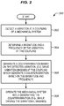
- FIG. 2 is a flowchart illustrating a method 200 for operating the coupling of FIG. 1 in an illustrative example.
- the steps of method 200 are described with reference to coupling 100 of FIG. 1 , but those skilled in the art will appreciate that method 200 may be performed in other systems.
- the steps of the flowcharts described herein are not all inclusive and may include other steps not shown. The steps described herein may also be performed in an alternative order.
- drive unit 120 detects a vibration at coupling 100.
- drive unit 120 may detect changes in resistance at one or more cantilevered piezoelectric sensors that are internally disposed within coupling 100 (e.g., as depicted in FIG. 10 ).
- drive unit 120 further determines a magnitude and a frequency of the vibration at coupling 100.
- the frequency is the rate at which the vibration cycles through the coupling 100, while the magnitude is the force or amount of displacement caused by the vibration at its peak.
- Drive unit 120 may further determine a direction of the vibration based on input from the sensors (e.g., as described with regard to FIG. 10 ). Based on this information, drive unit 120 identifies a countervibration that will cancel out the detected vibration.
- drive unit 120 In step 206, drive unit 120 generates a countervibration based on the detected vibration.
- drive unit 120 may drive vibration engines 140 at the coupling 100.
- the vibration engines 140 When driven, the vibration engines 140 generate a countervibration that corresponds with (e.g., matches) the magnitude and frequency of the vibration, yet is opposed to the direction of the vibration.
- the magnitude and the frequency of the countervibration may also be detected on an ongoing basis by any sensors at the coupling 100 in order to control the countervibration.
- the countervibration combines with the vibration to prevent the coupling from displacing during operation. Specifically, the countervibration generates a force at the coupling 100 that cancels out a force caused by the vibration. This continues in an ongoing process, such that at each instant during which the vibration is being experienced, the drive unit 120 generates countervibration to prevent displacement.
- Countervibrations of a desired direction are generated by selectively operating groups of the vibration engines 140 based on their spatial arrangement. Countervibrations of a desired frequency are created by operating the vibration engines 140 at that frequency.
- the vibration engines may be operated to apply forces vertically downwards and then upwards at the same rate, in synchrony with the vibration (i.e. the vibration engines 140 are driven to be in anti-phase with the vibrations such that the upward motion caused by the vibration is reduced or cancelled (including substantially cancelled).
- the vibration engines 140 producing a simultaneous equal (or substantially equal) and opposite downward motion driven by the vibration engines, and the downward motion caused by the vibration is cancelled by a synchronized equal (or substantially equal) and opposite upward motion driven by the vibration engines, such that the vibration is cancelled or substantially cancelled).
- this includes applying electrical energy intermittently at a frequency to a motor 132 (e.g., a solenoid motor), causing the motor to generate the countervibration at the frequency. While a slight delay (e.g., several microseconds, or several milliseconds) may exist between detection of a vibration and generation of a countervibration, the technique remains effective at damping vibrations received over time.
- a motor 132 e.g., a solenoid motor
- a slight delay e.g., several microseconds, or several milliseconds
- coupling 100 operates as a reactive system that detects, analyzes, and damps incoming vibrations.
- the mechanical system i.e., the robot
- countervibration is being generating (e.g., while the vibration engines 140 are driven).
- the vibration engines 140 provide damping, the mechanical system may operate without being affected by external vibrations.
- the robot may perform drilling via an end effector while vibration engines 140 are driven.
- This provides a technical benefit by enabling the mechanical system to operate an end effector without that end effector being displaced by mechanical vibration.
- the principles described herein may also be utilized to damp vibrations caused by an end effector, in order to prevent the end effector from generating vibrations at a base of a robot. This may be particularly beneficial for robots that utilize multiple end effectors at once.
- FIG. 3 is a perspective view of the coupling of FIG. 1 , wherein casing 110 has been removed in an illustrative example.
- FIG. 3 corresponds with view arrows 3 of FIG. 1 .
- drive unit 120 includes at least two of rings 150.
- Each ring 150 includes vibration engines 140. Rings 150 enable a geometric arrangement of vibration engines 140 that permits damping of vibrations received from a wide range of directions. Vibration engines 140 along each ring 150 are disposed at different angular positions.
- Each vibration engine 140 is depicted in the form of an eccentric flywheel (e.g., as depicted by eccentric flywheels 450 of FIG. 4 ) or cam.
- Each vibration engine 140 is magnetically shielded from other vibration engines 140 by shields 310.
- Shields 310 may be made of any suitable material that is opaque to magnetic fields, such as steel or an iron-nickel alloy.
- the shields 310 are rectangular in order to deflect a variety of potential angles of infiltration of magnetic fields. For example, shields 310 may deflect a magnetic pulse M from a motor 132 depicted in FIG. 3 , preventing the magnetic pulse M from driving more than one vibration engine.
- the shields 310 are thin in order to reduce weight at the coupling.
- vibration engines 140 selected from both rings 150 may be driven synchronously clockwise or counterclockwise.
- vibration engines 140 in one of rings 150 may be driven in the opposite direction as vibration engines 140 in another of rings 150, but at the same rate. That is, vibration engines 140 in one of ring 150 may be driven clockwise 320, while vibration engines 140 in the other ring may be driven counterclockwise 330 at the same rate. This prevents the vibration engines 140 from generating forces in line with the axial length L of drive unit 120.
- vibration engines 140 within a ring 150 in order to control displacement in directions 340 that are perpendicular to axial length L.
- components of vibration generated by one vibration engine 140 may be countered or amplified by actions of other vibration engines 140 in order to create a countervibration of desired direction, frequency, and amplitude.
- Selective activation of vibration engines 140 enables drive unit 120 to apply not just displacement, but also torque to coupling 100 in a controlled manner.
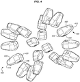
- FIG. 4 is a perspective view of an arrangement of vibration engines 140 within the coupling 100 of FIG. 1 in an illustrative example.
- FIG. 4 corresponds with view arrows 3 of FIG. 1 .
- This FIG. shows the vibration engines 140 without the other structural components shown in FIG. 3 ).
- each vibration engine 140 comprises an eccentric flywheel 450 having a magnetic portion having a tip 410 and a base 420.
- rings 150 to which eccentric flywheels 450 are attached, are omitted for the sake of enhancing clarity.
- the base 420 includes a hole 440 for receiving a ring 150. Tip 410 is distal from the hole 440, and therefore spins about ring 150 when eccentric flywheel 450 is operated.
- Tip 410 includes a magnetic portion 430 which may receive magnetic forces in order to initiate spinning, halt spinning, or change the direction of spinning for the eccentric flywheel 450. While in operation, one eccentric flywheel 450 may rotate in one direction, while a neighboring flywheel may rotate in the same or a different direction.
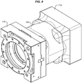
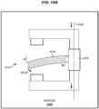
- FIG. 5 is a section cut side view of the coupling 100 of FIG. 1 in an illustrative example.
- FIG. 5 corresponds with view arrows 5 of FIG. 1 , and illustrates motors 132, vibration engines 140, and shields 310 within casing 110 from a different viewpoint.
- FIG. 6 is a section cut front view of the coupling of FIG. 1 in an illustrative example.
- FIG. 6 corresponds with view arrows 6 of FIG. 5 .
- FIG. 6 illustrates that the vibration engines 140 are arranged symmetrically within a ring 150.
- first vibration engine 610 and second vibration engine 620 are symmetrically disposed with respect to core 130.
- first vibration engine 610 and the second vibration engine 620 may be used in a coordinated fashion in order to apply countervibrations along or against direction D. Forces generated by the first vibration engine 610 and the second vibration engine 620 into or out of the page may be compensated by a similarly oriented pair of vibration engines in another ring 150.
- FIG. 7 is an exploded perspective view of the coupling of FIG. 1 accompanied by adapter 710 and adapter 730 in an illustrative example.
- Adapter 710 and adapter 730 enable coupling 700 to be attached between a kinematic chain of a robot (e.g., integrated into a robot arm) or other mechanical system and an end effector, in order to perform damping of mechanical vibrations between these elements.
- the coupling 100 may be positioned to damp vibrations at any location within any suitable mechanical system.
- coupling may be placed beneath the base of a robot in some examples.
- FIG. 7 also depicts a variety of mounting holes 720, which may receive bolts or other fasteners in order to affix adapter 710 and adapter 730 to coupling 100 and/or each other.
- FIG. 8 adapter 710 and adapter 730 have been attached to coupling 700 in order to facilitate integration of coupling 100 within a mechanical system.
- FIG. 9 is a diagram illustrating a robot 910 utilizing a coupling in an illustrative example.
- Robot 910 is disposed within fabrication environment 900, and performs work upon parts in order to fabricate those parts. For example, robot 910 may perform drilling, welding, riveting, etc. via an end effector 916. While robot 910 operates, vibrations 914 caused by vehicles 920 traveling within fabrication environment 900 are transferred along a kinematic chain 912 and travel towards end effector 916. The vibrations 914 combine with any vibrations created at the robot 910 to result in vibrations 915, which reach coupling 918.
- Coupling 918 is disposed between elements of the kinematic chain 912 and end effector 916, and generates countervibrations 930 that damp the vibrations 915. This stabilizes end effector 916 by preventing its displacement.
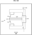
- FIG. 10A depicts further details of sensors that may be utilized within a coupling.
- the coupling actively damps mechanical vibration.
- FIG. 10 is a diagram illustrating a sensor 1010 within a coupling 1000.
- the sensor 1010 oscillates 1014 in response to vibrations in some examples.
- sensor 1010 comprises a cantilevered piezoelectric hair sensor 1016 that projects from base 1020 and exhibits a changing amount of electrical resistance R in response to deflection of its tip 1012.
- Sensor 1010 may be integrated, for example, into a Wheatstone bridge.
- the vibrations cause the tip 1012 to deflect an amount D as shown in FIG. 10B , the resistance of current pathway 1030 changes to R2.
- Changes in resistance caused by multiple sensors 1010 at different locations and orientations within the coupling 1000 may be electrically detected and analyzed in order to determine the magnitude and frequency of incoming vibrations. Because the orientations of sensors 1010 are known within the coupling, amounts of vibration from sensors 1010 at different orientations may be compared in order to determine a direction in which the vibration is occurring. This information may then be used to drive vibration engines disposed at the coupling.
- the coupling is configured to prevent itself from self-exciting in response to its own vibrations.
- a self-exciting state may occur, for example, if there are no external vibrations, the vibration engines comprise flywheels spinning at a steady state, and one of the flywheels becomes imbalanced. In such a circumstance, the vibrations of the imbalanced flywheel may be perceived by the hair sensors as external, which may speed up the imbalanced flywheel, resulting in an even greater increase in vibration.
- each of vibration detection sensors 160 depicted in FIG. 1 may monitor vibrations along a different axis, and each of motors 132 within FIG. 1 may include its own internal sensor.
- the overall current supplied to the drive unit may be controlled by input from the vibration detection sensors 160, while individual motors may be controlled by their own internal sensors.
- FIG. 11 is a flowchart illustrating a method 1100 of electrical control of a coupling to dynamically generate countervibration in an illustrative example.
- motors within a core of the coupling are electrically coupled with sensors such as those described above in FIG. 10 .
- one or more of the sensors receive mechanical vibrations which cause them to vibrate, resulting in an oscillating change in resistance.
- one or more motors at the coupling generate magnetic pulses at a rate corresponding with the rate of vibration of the sensors.
- the magnetic pulses cause eccentric flywheels to spin at the rate of the received mechanical vibration, but in the opposite direction to the received mechanical vibration. This results in a countervibration that stabilizes the coupling.
- the sampling rate of the sensors may be chosen to be at least the rate at which vibration engines at the coupling may oscillate.
- the sensors may sample at a rate of hundreds of times per second, or hundreds of thousands of times per second.
- FIG. 12 is a diagram 1200 illustrating a magnetically driven eccentric flywheel in an illustrative example.
- Eccentric flywheel 450 includes a magnetic portion 430, and is mounted to a ring 150, and is driven into motion by a motor 132 that generates magnetic pulses.
- motor 132 When eccentric flywheel 450 spins in direction 1250, in response to a pulsed magnetic force P from field generator 1230, it generates vibrations V in a controlled manner that counter detected vibrations at a coupling.
- Motor 132 is powered by power supply 1240.
- FIG. 13 is a diagram 1300 illustrating a vertical component 1310 of forces F applied by an eccentric flywheel 450 at various positions in an illustrative example.
- FIG. 13 illustrates that as an eccentric flywheel spins, it generates oscillating forces in the vertical direction.
- FIG. 14 is a diagram 1400 illustrating complementary eccentric flywheels in an illustrative example.
- FIG. 14 specifically illustrates how complementary flywheels may spin in a synchronized manner in order to generate forces in specific directions.
- FIG. 14 depicts a flywheel 1410 that generates a force F1 downward and to the left, and a flywheel 1420 that generates a force F2 upward and to the left.
- Flywheel 1410 spins counterclockwise, resulting in a moment A, while flywheel 1420 spins clockwise at the same rate, resulting in moment B of equal magnitude.
- Combined force F1+F2 generates net momentum laterally towards the left of the page in an oscillating fashion.
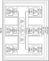
- FIG. 15 is a block diagram of a coupling 1500 in an illustrative example.
- Coupling 1500 includes a casing 1510 which surrounds a drive unit 1520.
- Motors 1532 within a core 1530 of drive unit 1520 are used to drive vibration engines 1540.
- Vibration engines 1540 are arranged in rings 1550, and are separated by shields 1560.
- Vibration engines 1540 may be implemented, for example, as flywheels.
- Shields 1560 prevent motors 1532 from driving multiple vibration engines 1540 at once, and hence enable vibration engines 1540 to be independently controlled.
- Controller 1570 receives input from sensors 1580, and controls operations of motors 1532 based on this input in order to generate countervibrations.
- controller 1570 may determine the magnitude, direction, and frequency of a received vibration at coupling 1500 based on input from sensors 1580. Controller 1570 may further drive complementary flywheels at rates equal to the frequency, in a direction opposed to the direction of the vibration, in order to counter the vibration. Controller 1570 may be implemented, for example, as custom circuitry, as a hardware processor executing programmed instructions, or some combination thereof.
- method 1600 may include specification and design 1604 of the aircraft 1602 and material procurement 1606.
- component and subassembly manufacturing 1608 and system integration 1610 of the aircraft 1602 takes place.
- the aircraft 1602 may go through certification and delivery 1612 in order to be placed in service 1614.
- the aircraft 1602 is scheduled for routine work in maintenance and service 1616 (which may also include modification, reconfiguration, refurbishment, and so on).
- Apparatus and methods embodied herein may be employed during any one or more suitable stages of the production and service described in method 1600 (e.g., specification and design 1604, material procurement 1606, component and subassembly manufacturing 1608, system integration 1610, certification and delivery 1612, service 1614, maintenance and service 1616) and/or any suitable component of aircraft 1602 (e.g., airframe 1618, systems 1620, interior 1622, propulsion system 1624, electrical system 1626, hydraulic system 1628, environmental system 1630).
- the apparatus described herein may facilitate vibrational isolation of systems 1620 from each other within an aircraft in service, may be used to damp vibrations in production and service, etc.
- a system integrator may include without limitation any number of aircraft manufacturers and major-system subcontractors; a third party may include without limitation any number of vendors, subcontractors, and suppliers; and an operator may be an airline, leasing company, military entity, service organization, and so on.
- the aircraft 1602 produced by method 1600 may include an airframe 1618 with a plurality of systems 1620 and an interior 1622.
- systems 1620 include one or more of a propulsion system 1624, an electrical system 1626, a hydraulic system 1628, and an environmental system 1630. Any number of other systems may be included.
- an aerospace example is shown, the principles of the disclosure may be applied to other industries, such as the automotive industry.
- apparatus and methods embodied herein may be employed during any one or more of the stages of the production and service described in method 1600.
- components or subassemblies corresponding to component and subassembly manufacturing 1608 may be fabricated or manufactured in a manner similar to components or subassemblies produced while the aircraft 1602 is in service.
- one or more apparatus examples, method examples, or a combination thereof may be utilized during the subassembly manufacturing 1608 and system integration 1610, for example, by expediting or substantially expediting assembly of or reducing the cost of an aircraft 1602.
- one or more of apparatus examples, method examples, or a combination thereof may be utilized while the aircraft 1602 is in service, for example and without limitation during the maintenance and service 1616.
- the techniques and systems described herein may be used for material procurement 1606, component and subassembly manufacturing 1608, system integration 1610, service 1614, and/or maintenance and service 1616, and/or may be used for airframe 1618 and/or interior 1622.
- systems 1620 including, for example, propulsion system 1624, electrical system 1626, hydraulic system 1628, and/or environmental system 1630.
- a part comprises a portion of airframe 1618, and is manufactured during component and subassembly manufacturing 1608.
- the part may then be assembled into an aircraft in system integration 1610, and then be utilized in service 1614 until wear renders the part unusable. Then, in maintenance and service 1616, the part may be discarded and replaced with a newly manufactured part.
- Inventive components and methods may be utilized throughout component and subassembly manufacturing 1608 in order to manufacture new parts.
- control elements e.g., electrical or electronic components
- a processor implementing software
- a processor implementing firmware or some combination of these.
- an element may be implemented as dedicated hardware.
- Dedicated hardware elements may be referred to as "processors", “controllers”, or some similar terminology.
- the functions may be provided by a single dedicated processor, by a single shared processor, or by a plurality of individual processors, some of which may be shared.
- processor or “controller” should not be construed to refer exclusively to hardware capable of executing software, and may implicitly include, without limitation, digital signal processor (DSP) hardware, a network processor, application specific integrated circuit (ASIC) or other circuitry, field programmable gate array (FPGA), read only memory (ROM) for storing software, random access memory (RAM), non-volatile storage, logic, or some other physical hardware component or module.
- DSP digital signal processor
- ASIC application specific integrated circuit
- FPGA field programmable gate array
- ROM read only memory
- RAM random access memory
- non-volatile storage logic, or some other physical hardware component or module.
- a control element may be implemented as instructions executable by a processor or a computer to perform the functions of the element.
- instructions are software, program code, and firmware.
- the instructions are operational when executed by the processor to direct the processor to perform the functions of the element.
- the instructions may be stored on storage devices that are readable by the processor. Some examples of the storage devices are digital or solid-state memories, magnetic storage media such as a magnetic disks and magnetic tapes, hard drives, or optically readable digital data storage media.
Abstract
Description
- The disclosure relates to the field of stabilization, and in particular, to damping mechanical vibrations.
- Mechanical vibrations may be encountered in a variety of vehicles and fabrication environments. For example, a robot in a fabrication environment may encounter vibrations resulting from the travel of nearby heavy vehicles, may encounter vibrations caused by generators or other machinery operating in the fabrication environment, and may even encounter vibrations caused by its own internal components. These vibrations are transmitted from the base of the robot along a kinematic chain of the robot to an end effector. Upon reaching the end effector, the vibrations may displace the end effector. This may adversely impact a locational precision of the end effector, or may otherwise hinder the ability of the end effector to operate effectively. Many of these vibrations are unexpected, and the range of frequencies and amplitudes for these vibrations may vary substantially.
- Mechanical vibrations may also be encountered in vehicles ranging from automobiles to mobile hospital beds. Damping mechanical vibrations for such vehicles may increase an amount of comfort and stability of those vehicles. Mechanical vibrations may even be encountered by scientific devices such as at the tip of an Atomic Force Microscopy (AFM) device. In such environments, it is desirable to reduce or control the transmission of unexpected vibrations to an end effector, in order to increase device accuracy.
- Therefore, it would be desirable to have a method and apparatus that take into account at least some of the issues discussed above, as well as other possible issues.
- Examples described herein actively detect and damp mechanical vibrations via a coupling that utilizes vibration engines (e.g., magnetically actuated flywheels, solenoid motors, etc.) in order to generate countervibrations in response to detected vibrations. These countervibrations damp the vibrations encountered by the coupling, which enables a device affixed to the coupling (e.g., an end effector) to be stabilized and protected from unexpected vibration.
- One example is a method for damping vibration in a mechanical system. The method includes detecting a vibration at a coupling of the mechanical system, generating a countervibration based on the detected vibration, and operating the mechanical system while generating the countervibration.
- A further example is a non-transitory computer readable medium embodying programmed instructions which, when executed by a processor, are operable for performing a method for damping vibration in a mechanical system. The method includes detecting a vibration at a coupling of the mechanical system, generating a countervibration based on the detected vibration, and operating the mechanical system while generating the countervibration.
- Yet another example is an apparatus for damping vibration in a mechanical system. The apparatus includes a coupling which includes vibration detection sensors at the coupling, vibration engines at the coupling, and a controller that is coupled for communication with the vibration sensors and the vibration engines, and is configured to determine a magnitude and a frequency of a vibration detected by the vibration detection sensors, and to direct the vibration engines to generate a countervibration based on the magnitude and the frequency.
- Other illustrative examples (e.g., methods and computer-readable media relating to the foregoing examples) may be described below. The features, functions, and advantages that have been discussed can be achieved independently in various examples or may be combined in yet other examples further details of which can be seen with reference to the following description and drawings.
- Some examples of the present disclosure are now described, by way of example only, and with reference to the accompanying drawings. The same reference number represents the same element or the same type of element on all drawings.
-
FIG. 1 is a perspective view of a coupling that actively damps vibration in an illustrative example. -
FIG. 2 is a flowchart illustrating a method for operating the coupling ofFIG. 1 in an illustrative example. -
FIG. 3 is a perspective view of the coupling ofFIG. 1 wherein a casing has been removed in an illustrative example. -
FIG. 4 is a perspective view of an arrangement of vibration engines within the coupling ofFIG. 1 in an illustrative example. -
FIG. 5 is a section cut side view of the coupling ofFIG. 1 in an illustrative example. -
FIG. 6 is a section cut front view of the coupling ofFIG. 1 in an illustrative example. -
FIG. 7 is an exploded perspective view of the coupling ofFIG. 1 accompanied by adapters in an illustrative example. -
FIG. 8 is a perspective view of the coupling ofFIG. 1 accompanied by adapters in an illustrative example. -
FIG. 9 is a diagram illustrating a robot utilizing a coupling in an illustrative example. -
FIGS. 10A-10B are diagrams illustrating a sensor within a coupling that oscillates in response to vibrations in an illustrative example. -
FIG. 11 is a flowchart illustrating electrical control of a coupling to dynamically generate countervibration in an illustrative example. -
FIG. 12 is a diagram illustrating a magnetically driven eccentric flywheel in an illustrative example. -
FIG. 13 is a diagram illustrating a vertical component of forces applied by an eccentric flywheel at various positions in an illustrative example. -
FIG. 14 is a diagram illustrating complementary eccentric flywheels in an illustrative example. -
FIG. 15 is a block diagram of a coupling within a fabrication environment in an illustrative example. -
FIG. 16 is a flow diagram of aircraft production and service methodology in an illustrative example. -
FIG. 17 is a block diagram of an aircraft in an illustrative example. - The figures and the following description provide specific illustrative examples of the disclosure. It will thus be appreciated that those skilled in the art will be able to devise various arrangements that, although not explicitly described or shown herein, embody the principles of the disclosure and are included within the scope of the disclosure. Furthermore, any examples described herein are intended to aid in understanding the principles of the disclosure, and are to be construed as being without limitation to such specifically recited examples and conditions. As a result, the disclosure is not limited to the specific examples or examples described below, but by the claims and their equivalents.
-
FIG. 1 is a perspective view of acoupling 100 that actively damps mechanical vibration in an illustrative example.Coupling 100 comprises any system, device, or component operable to actively detect and damp mechanical vibrations in an operating mechanical system (e.g., a robot). Unlike a passive damping device such as a mass of rubber,coupling 100 is capable of detecting incoming vibrations, and generating countervibrations that reduce the detected vibrations and may cancel or substantially cancel out the detected vibrations. This prevents the coupling from moving in response to received external vibrations. For example, a countervibration may match or substantially match the frequency and magnitude of a detected vibration, but be applied in the opposite or substantially the opposite direction. In this example, countervibrations at the coupling are generated substantially to cancel out the detected vibrations such that in any given instant, the coupling experiences less than a threshold amount of displacement (e.g., less than one millimeter, less than ten percent of an original magnitude of the vibrations, etc.). - In this example,
coupling 100 includescasing 110, which mechanically protects and houses adrive unit 120.Vibration detection sensors 160 atcoupling 100 may detect the frequency, direction, and/or magnitude of incoming vibrations.Drive unit 120 includes acore 130 ofmotors 132, andvibration engines 140 which are arranged inmultiple rings 150. As vibrations are detected bydrive unit 120,motors 132 are activated in order to selectively drive thevibration engines 140 to generate countervibrations (which result in vibration cancellation). Thevibration engines 140 may comprise electromagnetically actuated flywheels, Eccentric Rotating Mass (ERM) vibration motors, Linear Resonant Actuator (LRA) vibration motors, solenoid vibration motors, etc.Motors 132 may comprise magnetic field generators that apply torque to thevibration engines 140, or other components that apply forces which drive thevibration engines 140. - Illustrative details of the operation of
coupling 100 will be discussed with regard toFIG. 2 . Assume, for this example, thatcoupling 100 has been mounted to a mechanical system in the form of a robot. For example,coupling 100 may be disposed between a base of the robot and an end effector of the robot, in order to prevent vibrations received at the base of the robot from being transmitted to the end effector. The robot is intended to perform work at precise locations on a part. Further, assume that the robot is located within a factory that is subject to vibrations caused by moving vehicles or other equipment. Vibrations travel from a base of the robot through the coupling and into an end effector, which impacts a positional accuracy of the end effector during operations. -
FIG. 2 is a flowchart illustrating amethod 200 for operating the coupling ofFIG. 1 in an illustrative example. The steps ofmethod 200 are described with reference tocoupling 100 ofFIG. 1 , but those skilled in the art will appreciate thatmethod 200 may be performed in other systems. The steps of the flowcharts described herein are not all inclusive and may include other steps not shown. The steps described herein may also be performed in an alternative order. - In
step 202,drive unit 120 detects a vibration atcoupling 100. For example,drive unit 120 may detect changes in resistance at one or more cantilevered piezoelectric sensors that are internally disposed within coupling 100 (e.g., as depicted inFIG. 10 ). - In
step 204,drive unit 120 further determines a magnitude and a frequency of the vibration atcoupling 100. The frequency is the rate at which the vibration cycles through thecoupling 100, while the magnitude is the force or amount of displacement caused by the vibration at its peak.Drive unit 120 may further determine a direction of the vibration based on input from the sensors (e.g., as described with regard toFIG. 10 ). Based on this information,drive unit 120 identifies a countervibration that will cancel out the detected vibration. - In
step 206,drive unit 120 generates a countervibration based on the detected vibration. For example,drive unit 120 may drivevibration engines 140 at thecoupling 100. When driven, thevibration engines 140 generate a countervibration that corresponds with (e.g., matches) the magnitude and frequency of the vibration, yet is opposed to the direction of the vibration. The magnitude and the frequency of the countervibration may also be detected on an ongoing basis by any sensors at thecoupling 100 in order to control the countervibration. - The countervibration combines with the vibration to prevent the coupling from displacing during operation. Specifically, the countervibration generates a force at the
coupling 100 that cancels out a force caused by the vibration. This continues in an ongoing process, such that at each instant during which the vibration is being experienced, thedrive unit 120 generates countervibration to prevent displacement. Countervibrations of a desired direction are generated by selectively operating groups of thevibration engines 140 based on their spatial arrangement. Countervibrations of a desired frequency are created by operating thevibration engines 140 at that frequency. For example, if a vibration proceeds vertically upwards and then downwards at a known rate, then the vibration engines may be operated to apply forces vertically downwards and then upwards at the same rate, in synchrony with the vibration (i.e. thevibration engines 140 are driven to be in anti-phase with the vibrations such that the upward motion caused by the vibration is reduced or cancelled (including substantially cancelled). This is achieved by thevibration engines 140 producing a simultaneous equal (or substantially equal) and opposite downward motion driven by the vibration engines, and the downward motion caused by the vibration is cancelled by a synchronized equal (or substantially equal) and opposite upward motion driven by the vibration engines, such that the vibration is cancelled or substantially cancelled). In some examples, this includes applying electrical energy intermittently at a frequency to a motor 132 (e.g., a solenoid motor), causing the motor to generate the countervibration at the frequency. While a slight delay (e.g., several microseconds, or several milliseconds) may exist between detection of a vibration and generation of a countervibration, the technique remains effective at damping vibrations received over time. Hence,coupling 100 operates as a reactive system that detects, analyzes, and damps incoming vibrations. - In
step 208, the mechanical system (i.e., the robot) is operated while countervibration is being generating (e.g., while thevibration engines 140 are driven). Because thevibration engines 140 provide damping, the mechanical system may operate without being affected by external vibrations. For example, the robot may perform drilling via an end effector whilevibration engines 140 are driven. This provides a technical benefit by enabling the mechanical system to operate an end effector without that end effector being displaced by mechanical vibration. The principles described herein may also be utilized to damp vibrations caused by an end effector, in order to prevent the end effector from generating vibrations at a base of a robot. This may be particularly beneficial for robots that utilize multiple end effectors at once. -
FIG. 3 is a perspective view of the coupling ofFIG. 1 , wherein casing 110 has been removed in an illustrative example.FIG. 3 corresponds withview arrows 3 ofFIG. 1 . As shown inFIG. 3 ,drive unit 120 includes at least two ofrings 150. Eachring 150 includesvibration engines 140.Rings 150 enable a geometric arrangement ofvibration engines 140 that permits damping of vibrations received from a wide range of directions.Vibration engines 140 along eachring 150 are disposed at different angular positions. Eachvibration engine 140 is depicted in the form of an eccentric flywheel (e.g., as depicted byeccentric flywheels 450 ofFIG. 4 ) or cam. Eachvibration engine 140 is magnetically shielded fromother vibration engines 140 byshields 310. This allows eachvibration engine 140 to be independently driven by a different one ofmotors 132.Shields 310 may be made of any suitable material that is opaque to magnetic fields, such as steel or an iron-nickel alloy. Theshields 310 are rectangular in order to deflect a variety of potential angles of infiltration of magnetic fields. For example, shields 310 may deflect a magnetic pulse M from amotor 132 depicted inFIG. 3 , preventing the magnetic pulse M from driving more than one vibration engine. Theshields 310 are thin in order to reduce weight at the coupling. - In order to generate vibrations back and forth along the axial length L of
drive unit 120,vibration engines 140 selected from bothrings 150 may be driven synchronously clockwise or counterclockwise. Alternatively, in order to generate vibrations without movingdrive unit 120 back and forth axially,vibration engines 140 in one ofrings 150 may be driven in the opposite direction asvibration engines 140 in another ofrings 150, but at the same rate. That is,vibration engines 140 in one ofring 150 may be driven clockwise 320, whilevibration engines 140 in the other ring may be driven counterclockwise 330 at the same rate. This prevents thevibration engines 140 from generating forces in line with the axial length L ofdrive unit 120. Similar techniques may be used forvibration engines 140 within aring 150 in order to control displacement indirections 340 that are perpendicular to axial length L. Stated succinctly, components of vibration generated by onevibration engine 140 may be countered or amplified by actions ofother vibration engines 140 in order to create a countervibration of desired direction, frequency, and amplitude. Selective activation ofvibration engines 140 enablesdrive unit 120 to apply not just displacement, but also torque tocoupling 100 in a controlled manner. -
FIG. 4 is a perspective view of an arrangement ofvibration engines 140 within thecoupling 100 ofFIG. 1 in an illustrative example.FIG. 4 corresponds withview arrows 3 ofFIG. 1 . This FIG. shows thevibration engines 140 without the other structural components shown inFIG. 3 ). InFIG. 4 , eachvibration engine 140 comprises aneccentric flywheel 450 having a magnetic portion having atip 410 and abase 420. Note that rings 150, to whicheccentric flywheels 450 are attached, are omitted for the sake of enhancing clarity. Thebase 420 includes ahole 440 for receiving aring 150.Tip 410 is distal from thehole 440, and therefore spins aboutring 150 wheneccentric flywheel 450 is operated.Tip 410 includes amagnetic portion 430 which may receive magnetic forces in order to initiate spinning, halt spinning, or change the direction of spinning for theeccentric flywheel 450. While in operation, oneeccentric flywheel 450 may rotate in one direction, while a neighboring flywheel may rotate in the same or a different direction. -
FIG. 5 is a section cut side view of thecoupling 100 ofFIG. 1 in an illustrative example.FIG. 5 corresponds withview arrows 5 ofFIG. 1 , and illustratesmotors 132,vibration engines 140, and shields 310 within casing 110 from a different viewpoint.FIG. 6 is a section cut front view of the coupling ofFIG. 1 in an illustrative example.FIG. 6 corresponds withview arrows 6 ofFIG. 5 .FIG. 6 illustrates that thevibration engines 140 are arranged symmetrically within aring 150. For example,first vibration engine 610 andsecond vibration engine 620 are symmetrically disposed with respect tocore 130. Hence, thefirst vibration engine 610 and thesecond vibration engine 620 may be used in a coordinated fashion in order to apply countervibrations along or against direction D. Forces generated by thefirst vibration engine 610 and thesecond vibration engine 620 into or out of the page may be compensated by a similarly oriented pair of vibration engines in anotherring 150. -
FIG. 7 is an exploded perspective view of the coupling ofFIG. 1 accompanied byadapter 710 andadapter 730 in an illustrative example.Adapter 710 andadapter 730 enablecoupling 700 to be attached between a kinematic chain of a robot (e.g., integrated into a robot arm) or other mechanical system and an end effector, in order to perform damping of mechanical vibrations between these elements. However, in further examples thecoupling 100 may be positioned to damp vibrations at any location within any suitable mechanical system. For example, coupling may be placed beneath the base of a robot in some examples.FIG. 7 also depicts a variety of mountingholes 720, which may receive bolts or other fasteners in order to affixadapter 710 andadapter 730 tocoupling 100 and/or each other. InFIG. 8 ,adapter 710 andadapter 730 have been attached tocoupling 700 in order to facilitate integration ofcoupling 100 within a mechanical system. -
FIG. 9 is a diagram illustrating arobot 910 utilizing a coupling in an illustrative example.Robot 910 is disposed withinfabrication environment 900, and performs work upon parts in order to fabricate those parts. For example,robot 910 may perform drilling, welding, riveting, etc. via anend effector 916. Whilerobot 910 operates,vibrations 914 caused byvehicles 920 traveling withinfabrication environment 900 are transferred along akinematic chain 912 and travel towardsend effector 916. Thevibrations 914 combine with any vibrations created at therobot 910 to result invibrations 915, which reachcoupling 918. This may affect positional control atend effector 916, which may impact the accuracy ofend effector 916 during operation or otherwise impair the quality of fabrication of parts being worked on. Coupling 918 is disposed between elements of thekinematic chain 912 andend effector 916, and generatescountervibrations 930 that damp thevibrations 915. This stabilizesend effector 916 by preventing its displacement. -
FIG. 10A depicts further details of sensors that may be utilized within a coupling. The coupling actively damps mechanical vibration. Specifically,FIG. 10 is a diagram illustrating asensor 1010 within a coupling 1000. Thesensor 1010 oscillates 1014 in response to vibrations in some examples. In this example,sensor 1010 comprises a cantileveredpiezoelectric hair sensor 1016 that projects frombase 1020 and exhibits a changing amount of electrical resistance R in response to deflection of itstip 1012.Sensor 1010 may be integrated, for example, into a Wheatstone bridge. When mechanical vibrations travel through the coupling, the vibrations cause thetip 1012 to deflect an amount D as shown inFIG. 10B , the resistance ofcurrent pathway 1030 changes to R2. In short, when the hair sensor vibrates, its resistance changes. In a suitably designed system, this leads to a change in current alongcurrent pathway 1030. The increase in current causes magnetic pulse generators to apply more force to vibration engines, which spin faster since there is more magnetic force being applied to their tips. - Changes in resistance caused by
multiple sensors 1010 at different locations and orientations within the coupling 1000 may be electrically detected and analyzed in order to determine the magnitude and frequency of incoming vibrations. Because the orientations ofsensors 1010 are known within the coupling, amounts of vibration fromsensors 1010 at different orientations may be compared in order to determine a direction in which the vibration is occurring. This information may then be used to drive vibration engines disposed at the coupling. - In further examples, the coupling is configured to prevent itself from self-exciting in response to its own vibrations. A self-exciting state may occur, for example, if there are no external vibrations, the vibration engines comprise flywheels spinning at a steady state, and one of the flywheels becomes imbalanced. In such a circumstance, the vibrations of the imbalanced flywheel may be perceived by the hair sensors as external, which may speed up the imbalanced flywheel, resulting in an even greater increase in vibration.
- In order to prevent such self-excited states, in some examples, there are three more hair sensors than the total number of vibration engines. These additional hair sensors govern the overall current being supplied to the rest of the drive unit within the coupling. They each are orientated to monitor one of the three axes along which vibrations are received at the coupling, and may be used to distinguish external from self-induced internal vibrations. For example, each of
vibration detection sensors 160 depicted inFIG. 1 may monitor vibrations along a different axis, and each ofmotors 132 withinFIG. 1 may include its own internal sensor. The overall current supplied to the drive unit may be controlled by input from thevibration detection sensors 160, while individual motors may be controlled by their own internal sensors. -
FIG. 11 is a flowchart illustrating amethod 1100 of electrical control of a coupling to dynamically generate countervibration in an illustrative example. Assume, for this example, that motors within a core of the coupling are electrically coupled with sensors such as those described above inFIG. 10 . Instep 1102, one or more of the sensors receive mechanical vibrations which cause them to vibrate, resulting in an oscillating change in resistance. Instep 1104, one or more motors at the coupling generate magnetic pulses at a rate corresponding with the rate of vibration of the sensors. Instep 1106, the magnetic pulses cause eccentric flywheels to spin at the rate of the received mechanical vibration, but in the opposite direction to the received mechanical vibration. This results in a countervibration that stabilizes the coupling. Input from the sensors is used to adjust countervibrations on an ongoing basis. Thus, the sampling rate of the sensors may be chosen to be at least the rate at which vibration engines at the coupling may oscillate. For example, the sensors may sample at a rate of hundreds of times per second, or hundreds of thousands of times per second. -
FIG. 12 is a diagram 1200 illustrating a magnetically driven eccentric flywheel in an illustrative example.Eccentric flywheel 450 includes amagnetic portion 430, and is mounted to aring 150, and is driven into motion by amotor 132 that generates magnetic pulses. Wheneccentric flywheel 450 spins indirection 1250, in response to a pulsed magnetic force P from field generator 1230, it generates vibrations V in a controlled manner that counter detected vibrations at a coupling.Motor 132 is powered bypower supply 1240. -
FIG. 13 is a diagram 1300 illustrating avertical component 1310 of forces F applied by aneccentric flywheel 450 at various positions in an illustrative example.FIG. 13 illustrates that as an eccentric flywheel spins, it generates oscillating forces in the vertical direction. -
FIG. 14 is a diagram 1400 illustrating complementary eccentric flywheels in an illustrative example.FIG. 14 specifically illustrates how complementary flywheels may spin in a synchronized manner in order to generate forces in specific directions.FIG. 14 depicts aflywheel 1410 that generates a force F1 downward and to the left, and aflywheel 1420 that generates a force F2 upward and to the left.Flywheel 1410 spins counterclockwise, resulting in a moment A, whileflywheel 1420 spins clockwise at the same rate, resulting in moment B of equal magnitude. When synchronized as shown inFIG. 14 , this means that the flywheels cancel out each other's moments, yet generate a combined force F1+F2 composed of force F1 and force F2 while spinning. Combined force F1+F2 generates net momentum laterally towards the left of the page in an oscillating fashion. These principles may be expanded out to couplings such ascoupling 100 ofFIG. 1 in order to programmatically generate vibrations in any desired direction. - In the following examples, additional processes, systems, and methods are described in the context of a coupling that actively damps mechanical vibration.
-
FIG. 15 is a block diagram of acoupling 1500 in an illustrative example.Coupling 1500 includes acasing 1510 which surrounds adrive unit 1520.Motors 1532 within acore 1530 ofdrive unit 1520 are used to drivevibration engines 1540.Vibration engines 1540 are arranged inrings 1550, and are separated byshields 1560.Vibration engines 1540 may be implemented, for example, as flywheels.Shields 1560 preventmotors 1532 from drivingmultiple vibration engines 1540 at once, and hence enablevibration engines 1540 to be independently controlled.Controller 1570 receives input fromsensors 1580, and controls operations ofmotors 1532 based on this input in order to generate countervibrations. For example,controller 1570 may determine the magnitude, direction, and frequency of a received vibration atcoupling 1500 based on input fromsensors 1580.Controller 1570 may further drive complementary flywheels at rates equal to the frequency, in a direction opposed to the direction of the vibration, in order to counter the vibration.Controller 1570 may be implemented, for example, as custom circuitry, as a hardware processor executing programmed instructions, or some combination thereof. - Referring more particularly to the drawings, examples of the disclosure may be described in the context of aircraft manufacturing and service in
method 1600 as shown inFIG. 16 and anaircraft 1602 as shown inFIG. 17 . During pre-production,method 1600 may include specification anddesign 1604 of theaircraft 1602 andmaterial procurement 1606. During production, component andsubassembly manufacturing 1608 andsystem integration 1610 of theaircraft 1602 takes place. Thereafter, theaircraft 1602 may go through certification anddelivery 1612 in order to be placed inservice 1614. While in service by a customer, theaircraft 1602 is scheduled for routine work in maintenance and service 1616 (which may also include modification, reconfiguration, refurbishment, and so on). Apparatus and methods embodied herein may be employed during any one or more suitable stages of the production and service described in method 1600 (e.g., specification anddesign 1604,material procurement 1606, component andsubassembly manufacturing 1608,system integration 1610, certification anddelivery 1612,service 1614, maintenance and service 1616) and/or any suitable component of aircraft 1602 (e.g.,airframe 1618,systems 1620, interior 1622,propulsion system 1624,electrical system 1626,hydraulic system 1628, environmental system 1630). For example, the apparatus described herein may facilitate vibrational isolation ofsystems 1620 from each other within an aircraft in service, may be used to damp vibrations in production and service, etc. - Each of the processes of
method 1600 may be performed or carried out by a system integrator, a third party, and/or an operator (e.g., a customer). For the purposes of this description, a system integrator may include without limitation any number of aircraft manufacturers and major-system subcontractors; a third party may include without limitation any number of vendors, subcontractors, and suppliers; and an operator may be an airline, leasing company, military entity, service organization, and so on. - As shown in
FIG. 17 , theaircraft 1602 produced bymethod 1600 may include anairframe 1618 with a plurality ofsystems 1620 and an interior 1622. Examples ofsystems 1620 include one or more of apropulsion system 1624, anelectrical system 1626, ahydraulic system 1628, and anenvironmental system 1630. Any number of other systems may be included. Although an aerospace example is shown, the principles of the disclosure may be applied to other industries, such as the automotive industry. - As already mentioned above, apparatus and methods embodied herein may be employed during any one or more of the stages of the production and service described in
method 1600. For example, components or subassemblies corresponding to component andsubassembly manufacturing 1608 may be fabricated or manufactured in a manner similar to components or subassemblies produced while theaircraft 1602 is in service. Also, one or more apparatus examples, method examples, or a combination thereof may be utilized during thesubassembly manufacturing 1608 andsystem integration 1610, for example, by expediting or substantially expediting assembly of or reducing the cost of anaircraft 1602. Similarly, one or more of apparatus examples, method examples, or a combination thereof may be utilized while theaircraft 1602 is in service, for example and without limitation during the maintenance andservice 1616. For example, the techniques and systems described herein may be used formaterial procurement 1606, component andsubassembly manufacturing 1608,system integration 1610,service 1614, and/or maintenance andservice 1616, and/or may be used forairframe 1618 and/or interior 1622. These techniques and systems may even be utilized forsystems 1620, including, for example,propulsion system 1624,electrical system 1626,hydraulic system 1628, and/orenvironmental system 1630. - In some examples, a part comprises a portion of
airframe 1618, and is manufactured during component andsubassembly manufacturing 1608. The part may then be assembled into an aircraft insystem integration 1610, and then be utilized inservice 1614 until wear renders the part unusable. Then, in maintenance andservice 1616, the part may be discarded and replaced with a newly manufactured part. Inventive components and methods may be utilized throughout component andsubassembly manufacturing 1608 in order to manufacture new parts. - Any of the various control elements (e.g., electrical or electronic components) shown in the figures or described herein may be implemented as hardware, a processor implementing software, a processor implementing firmware, or some combination of these. For example, an element may be implemented as dedicated hardware. Dedicated hardware elements may be referred to as "processors", "controllers", or some similar terminology. When provided by a processor, the functions may be provided by a single dedicated processor, by a single shared processor, or by a plurality of individual processors, some of which may be shared. Moreover, explicit use of the term "processor" or "controller" should not be construed to refer exclusively to hardware capable of executing software, and may implicitly include, without limitation, digital signal processor (DSP) hardware, a network processor, application specific integrated circuit (ASIC) or other circuitry, field programmable gate array (FPGA), read only memory (ROM) for storing software, random access memory (RAM), non-volatile storage, logic, or some other physical hardware component or module.
- Also, a control element may be implemented as instructions executable by a processor or a computer to perform the functions of the element. Some examples of instructions are software, program code, and firmware. The instructions are operational when executed by the processor to direct the processor to perform the functions of the element. The instructions may be stored on storage devices that are readable by the processor. Some examples of the storage devices are digital or solid-state memories, magnetic storage media such as a magnetic disks and magnetic tapes, hard drives, or optically readable digital data storage media.
- Clause 1: A method for damping vibration in a mechanical system, the method comprising detecting a vibration at a coupling of the mechanical system; generating a countervibration based on the detected vibration; and operating the mechanical system while generating the countervibration.
- Clause 2: The method of Clause 1 further comprising determining a magnitude and a frequency of the vibration at the coupling, wherein generating the countervibration comprises driving vibration engines at the coupling based on the magnitude and the frequency of the detected vibration.
- Clause 3: The method of Clause 2 wherein generating the countervibration comprises driving the vibration engines at the coupling with the magnitude and the frequency of the detected vibration so as to reduce, cancel out or substantially cancel out the detected vibration.
- Clause 4: The method of
Clause 2 or 3 further comprising determining a direction of the vibration at the coupling, and wherein generating the countervibration comprises driving vibration engines at the coupling such that the countervibration matches or substantially matches the frequency and magnitude of the detected vibration and is applied in the opposite direction or substantially the opposite direction to the direction of the vibration at the coupling. - Clause 5: The method of any of Clauses 2-4 wherein generating the countervibration comprises driving the vibration engines to be in anti-phase with the detected vibration.
- Clause 6: The method of
Clause 4 or 5 wherein a first motion in a first direction caused by the detected vibration is reduced, cancelled or substantially cancelled by driving the vibration engines to cause a synchronized, second motion in a second direction, wherein the first and second motions are of equal or substantially magnitude and the second direction is opposite or substantially opposite to the first direction. - Clause 7: The method of any of Clauses 2-6 wherein determining the magnitude and the frequency of the vibration comprises detecting changes in resistance at piezoelectric sensors disposed at the coupling, and calculating the magnitude and the frequency based on the changes in resistance over time.
- Clause 8: The method of any of Clauses 2-7 further comprising any of: (a) driving the vibration engines prior to detecting the vibration to generate complementary vibrations that combine at the coupling without or substantially without displacing the coupling, (b) driving the vibration engines prior to detecting the vibration to generate vibrations that combine destructively at the coupling such that there is no displacement or substantially no displacement of the coupling, (c) driving the vibration engines when no vibration is detected to generate complementary vibrations that combine at the coupling without or substantially without displacing the coupling or (d) driving the vibration engines when no vibration is detected to generate vibrations that combine destructively at the coupling such that there is no displacement or substantially no displacement of the coupling.
- Clause 9: The method of any of Clauses 6-8 wherein driving the vibration engines comprises applying magnetic forces to flywheels disposed at the coupling.
- Clause 10: The method of Clause 9 wherein the magnetic forces are applied intermittently to the flywheels to generate the countervibration.
- Clause 11: The method of any of Clauses 6-10 wherein driving the vibration engines comprises applying electrical energy to a solenoid motor disposed at the coupling.
- Clause 12: The method of Clause 11 wherein the electrical energy is applied at a frequency to the solenoid motor, causing the solenoid motor to generate the countervibration at the frequency.
- Clause 13: The method of any of Clauses 6-12 wherein driving the vibration engines comprises selectively rotating flywheels that are disposed at different angular positions along a ring within the coupling.
- Clause 14: A portion of an aircraft assembled according to the method of any of Clauses 1-13.
- Clause 15: A non-transitory computer readable medium embodying programmed instructions which, when executed by a processor, are operable for performing a method for damping vibration in a mechanical system, the method comprising detecting a vibration at a coupling of the mechanical system; generating a countervibration based on the detected vibration; and operating the mechanical system while generating the countervibration.
- Clause 16: The medium of Clause 15 wherein the method further comprises determining a magnitude and a frequency of the vibration at the coupling, wherein generating the countervibration comprises driving vibration engines at the coupling based on the magnitude and the frequency of the detected vibration.
- Clause 17: The medium of Clause 16 wherein determining the magnitude and the frequency of the vibration comprises detecting changes in resistance at piezoelectric sensors disposed at the coupling and calculating the magnitude and the frequency based on the changes in resistance over time.
- Clause 18: The medium of Clause 16 or Clause 17 wherein the method further comprises driving the vibration engines prior to detecting the vibration to generate complementary vibrations that combine at the coupling without displacing the coupling.
- Clause 19: The medium of any of Clauses 16-18 wherein driving the vibration engines comprises applying magnetic forces to flywheels disposed at the coupling.
- Clause 20: The medium of Clause 19 wherein the magnetic forces are applied intermittently to the flywheels to generate the countervibration.
- Clause 21: The medium of any of Clauses 16-20 wherein the method further comprises driving the vibration engines comprises applying electrical energy to a solenoid motor disposed at the coupling.
- Clause 22: The medium of Clause 21 wherein the electrical energy is applied at a frequency to the solenoid motor, causing the solenoid motor to generate the countervibration at the frequency.
- Clause 23: The medium of any of Clauses 16-22 wherein driving the vibration engines comprises selectively rotating flywheels that are disposed at different angular positions along a ring within the coupling.
- Clause 24: A portion of an aircraft assembled according to the method defined by the instructions stored on the computer readable medium of any of Clauses 15-23.
- Clause 25: An apparatus for damping vibration in a mechanical system, the apparatus comprising a coupling comprising vibration detection sensors at the coupling; vibration engines at the coupling; and a controller that is coupled for communication with the vibration detection sensors and the vibration engines, and is configured to determine a magnitude and a frequency of a vibration detected by the vibration detection sensors, and to direct the vibration engines to generate a countervibration based on the magnitude and the frequency.
- Clause 26: The apparatus of Clause 25 wherein the vibration engines are arranged in multiple rings, each ring including vibration engines disposed at different angular positions.
- Clause 27: The apparatus of Clause 25 or Clause 26 further comprising pulse generators that apply magnetic forces to the vibration engines.
- Clause 28: The apparatus of Clause 27 wherein each pulse generator applies magnetic forces to a different vibration engine, and the apparatus further comprises magnetic shielding that isolates each vibration engine and corresponding pulse generator from other engines and pulse generators.
- Clause 29: Fabricating a portion of an aircraft using the apparatus of any of Clauses 25-28.
- Clause 30: A method of manufacturing a part, sub-assembly, product or vehicle using a mechanical system, comprising the method for damping vibration of any of Clauses 1 to 13 while using the mechanical system to manufacture the part, sub-assembly, product or vehicle.
- Clause 31: A method of manufacturing an aircraft part, an aircraft sub-assembly or an aircraft using a mechanical system, comprising the method for damping vibration of any of Clauses 1 to 13 while using the mechanical system to manufacture the aircraft part, aircraft sub-assembly or aircraft.
- Clause 32: A computer program comprising computer program instructions that, when executed by a computer processor, cause the computer processor to perform the method of any of Clauses 1 to 13.
- Clause 33: A non-transitory computer readable medium having stored therein the computer program of Clause 32.
- Clause 34: A computer system comprising a computer processor and a memory, wherein the memory has stored therein computer program instructions that, when executed by the computer processor, cause the computer system to perform the method of any of Clauses 1 to 13.
- Clause 35: Manufacturing equipment comprising a mechanical system for manufacturing a part, sub-assembly, product or vehicle, and a computer system comprising a computer processor and a memory, wherein the memory has stored therein computer program instructions that, when executed by the computer processor, cause the manufacturing equipment to perform the method of any of Clauses 1 to 13.
- Clause 36: The manufacturing equipment of Clause 35 comprising a coupling, vibration detection sensors at the coupling; and vibration engines at the coupling; and wherein the computer system is coupled for communication with the vibration detection sensors and the vibration engines, and is configured to determine a magnitude and a frequency of a vibration detected by the vibration detection sensors, and to direct the vibration engines to generate the countervibration based on the magnitude and the frequency.
- Clause 37: The manufacturing equipment of Clause 36 wherein the vibration engines are arranged in multiple rings, each ring including vibration engines disposed at different angular positions.
- Clause 38: The manufacturing equipment of Clause 36 or Clause 37 further comprising pulse generators that apply magnetic forces to the vibration engines.
- Clause 39: The manufacturing equipment of Clause 38 wherein each pulse generator applies magnetic forces to a different vibration engine, and the manufacturing equipment further comprises magnetic shielding that isolates each vibration engine and corresponding pulse generator from other engines and pulse generators.
- Clause 40: Aircraft manufacturing equipment comprising a mechanical system for manufacturing an aircraft part, an aircraft sub-assembly or an aircraft, and a computer system comprising a computer processor and a memory, wherein the memory has stored therein computer program instructions that, when executed by the computer processor, cause the aircraft manufacturing equipment to perform the method of any of Clauses 1 to 13.
- Clause 41: The aircraft manufacturing equipment of Clause 40, comprising a coupling, vibration detection sensors at the coupling, and vibration engines at the coupling; and wherein the computer system is coupled for communication with the vibration detection sensors and the vibration engines, and is configured to determine a magnitude and a frequency of a vibration detected by the vibration detection sensors, and to direct the vibration engines to generate the countervibration based on the magnitude and the frequency.
- Clause 42: The aircraft manufacturing equipment of Clause 41 wherein the vibration engines are arranged in multiple rings, each ring including vibration engines disposed at different angular positions.
- Clause 43: The aircraft manufacturing equipment of Clause 41 or Clause 42 further comprising pulse generators that apply magnetic forces to the vibration engines.
- Clause 44: The aircraft manufacturing equipment of Clause 43 wherein each pulse generator applies magnetic forces to a different vibration engine, and the aircraft manufacturing equipment further comprises magnetic shielding that isolates each vibration engine and corresponding pulse generator from other engines and pulse generators.
- Although specific examples are described herein, the scope of the disclosure is not limited to those specific examples. The scope of the disclosure is defined by the following claims and any equivalents thereof.
Claims (15)
- A method for damping vibration in a mechanical system, the method comprising:detecting a vibration at a coupling of the mechanical system;generating a countervibration based on the detected vibration; andoperating the mechanical system while generating the countervibration.
- The method of claim 1 further comprising:determining a magnitude and a frequency of the vibration at the coupling, whereingenerating the countervibration comprises driving vibration engines at the coupling based on the magnitude and the frequency of the detected vibration;and, optionally, wherein generating the countervibration comprises:
driving the vibration engines at the coupling with the magnitude and the frequency of the detected vibration so as to reduce, cancel out or substantially cancel out the detected vibration. - The method of claim 2 further comprising:determining a direction of the vibration at the coupling; andwherein generating the countervibration comprises driving the vibration engines at the coupling such that the countervibration matches or substantially matches the frequency and the magnitude of the detected vibration and is applied in the opposite direction or substantially the opposite direction to the direction of the vibration at the coupling;and, optionally, wherein:
generating the countervibration comprises driving the vibration engines to be in anti-phase with the detected vibration. - The method of claim 3 wherein:
a first motion in a first direction caused by the detected vibration is reduced, cancelled substantially cancelled by driving the vibration engines to cause a synchronized, second motion in a second direction, wherein the first and second motions are of equal or substantially magnitude and the second direction is opposite or substantially opposite to the first direction. - The method of any of claims 2-4 wherein:
determining the magnitude and the frequency of the vibration comprises:detecting changes in resistance at piezoelectric sensors disposed at the coupling; andcalculating the magnitude and the frequency based on the changes in resistance over time. - The method of any of claims 2-5 further comprising any of:(a) driving the vibration engines prior to detecting the vibration to generate complementary vibrations that combine at the coupling without or substantially without displacing the coupling;(b) driving the vibration engines prior to detecting the vibration to generate vibrations that combine destructively at the coupling such that there is no displacement or substantially no displacement of the coupling;(c) driving the vibration engines when no vibration is detected to generate complementary vibrations that combine at the coupling without or substantially without displacing the coupling; or(d) driving the vibration engines when no vibration is detected to generate vibrations that combine destructively at the coupling such that there is no displacement or substantially no displacement of the coupling.
- The method of any of claims 2-6 wherein:driving the vibration engines comprises applying magnetic forces to flywheels disposed at the coupling, and wherein the magnetic forces are applied intermittently to the flywheels to generate the countervibration; ordriving the vibration engines comprises applying electrical energy to a solenoid motor disposed at the coupling, and wherein the electrical energy is applied at the frequency to the solenoid motor, causing the solenoid motor to generate the countervibration at the frequency.
- A method of manufacturing an aircraft part, an aircraft sub-assembly or an aircraft using a mechanical system, comprising:
the method for damping vibration of any of claims 1 to 7 while using the mechanical system to manufacture the aircraft part, the aircraft sub-assembly or the aircraft. - A computer program comprising computer program instructions that, when executed by a computer processor, cause the computer processor to perform the method of any of claims 1 to 7.
- A computer system comprising:a computer processor; anda memory;wherein the memory has stored therein computer program instructions that, when executed by the computer processor, cause the computer system to perform the method of any of claims 1 to 7.
- Manufacturing equipment comprising:a mechanical system for manufacturing a part, sub-assembly, product or vehicle; anda computer system comprising:a computer processor; anda memory;wherein the memory has stored therein computer program instructions that, when executed by the computer processor, cause the manufacturing equipment to perform the method of any of claims 1 to 7.
- The manufacturing equipment of claim 11 comprising:a coupling;vibration detection sensors at the coupling; andvibration engines at the coupling; and wherein:
the computer system is coupled for communication with the vibration detection sensors and the vibration engines, and is configured:to determine a magnitude and a frequency of a vibration detected by the vibration detection sensors, andto direct the vibration engines to generate the countervibration based on the magnitude and the frequency. - The manufacturing equipment of claim 12 wherein:
the vibration engines are arranged in multiple rings, each ring including vibration engines disposed at different angular positions. - The manufacturing equipment of claim 12 or claim 13 further comprising:
pulse generators that apply magnetic forces to the vibration engines; and wherein:each pulse generator applies magnetic forces to a different vibration engine; andthe manufacturing equipment further comprises magnetic shielding that isolates each vibration engine and corresponding pulse generator from other engines and pulse generators. - The manufacturing equipment of any of claims 12 to 14, wherein:
the manufacturing equipment is aircraft manufacturing equipment comprising a mechanical system for manufacturing an aircraft part, an aircraft sub-assembly or an aircraft.
Applications Claiming Priority (1)
| Application Number | Priority Date | Filing Date | Title |
|---|---|---|---|
| US16/245,972 US11028898B2 (en) | 2019-01-11 | 2019-01-11 | Couplings that actively stabilize vibrations |
Publications (2)
| Publication Number | Publication Date |
|---|---|
| EP3690277A1 true EP3690277A1 (en) | 2020-08-05 |
| EP3690277B1 EP3690277B1 (en) | 2022-04-13 |
Family
ID=68618013
Family Applications (1)
| Application Number | Title | Priority Date | Filing Date |
|---|---|---|---|
| EP19209923.2A Active EP3690277B1 (en) | 2019-01-11 | 2019-11-19 | Couplings that actively stabilize vibrations |
Country Status (5)
| Country | Link |
|---|---|
| US (1) | US11028898B2 (en) |
| EP (1) | EP3690277B1 (en) |
| JP (1) | JP2020122571A (en) |
| KR (1) | KR20200088203A (en) |
| CN (1) | CN111434946B (en) |
Families Citing this family (1)
| Publication number | Priority date | Publication date | Assignee | Title |
|---|---|---|---|---|
| US11028898B2 (en) * | 2019-01-11 | 2021-06-08 | The Boeing Company | Couplings that actively stabilize vibrations |
Citations (5)
| Publication number | Priority date | Publication date | Assignee | Title |
|---|---|---|---|---|
| US5761940A (en) * | 1994-11-09 | 1998-06-09 | Amada Company, Ltd. | Methods and apparatuses for backgaging and sensor-based control of bending operations |
| EP1001184A2 (en) * | 1998-11-09 | 2000-05-17 | Lord Corporation | Vibration-damped machine and control method therefor |
| EP1621794A1 (en) * | 2004-07-29 | 2006-02-01 | Anorad Corporation | Damping and stabilization for linear motor stage |
| DE102008005300A1 (en) * | 2007-05-25 | 2008-11-27 | Wulfsberg, Jens Peter, Prof. Dr.-Ing. | Kinematics method and device for stabilizing serial and parallel kinematics combines multiple flywheels in a flywheel system arranged offset at an angle to each other in their axes |
| EP2016921A2 (en) * | 2007-07-20 | 2009-01-21 | Carl Zeiss Surgical GmbH | Tripod assembly and tripod for a medical-optical instrument |
Family Cites Families (12)
| Publication number | Priority date | Publication date | Assignee | Title |
|---|---|---|---|---|
| US5693990A (en) * | 1994-09-06 | 1997-12-02 | Bridgestone Corporation | Vibration isolating apparatus and vibration isolating table |
| US6095547A (en) * | 1995-08-01 | 2000-08-01 | K-2 Corporation | Active piezoelectric damper for a snow ski or snowboard |
| FR2781938B1 (en) * | 1998-07-30 | 2003-09-19 | Hutchinson | ELECTROMAGNETIC MOTOR AND ACTIVE VIBRATION CONTROL DEVICE INCLUDING AT LEAST ONE SUCH MOTOR |
| JP2002221249A (en) * | 2000-11-27 | 2002-08-09 | Canon Inc | Active damping unit, its controlling method, and exposure system having active damping unit |
| CN102338191B (en) * | 2011-07-01 | 2013-06-05 | 三一重工股份有限公司 | Arm support vibration suppression method and system as well as arm-support-type engineering machinery |
| KR20130055472A (en) * | 2011-11-18 | 2013-05-28 | 현대자동차주식회사 | Vibration controling system of power train for vehicle and controlling method thereof |
| US9233753B2 (en) * | 2013-07-24 | 2016-01-12 | Sikorsky Aircraft Corporation | Helicopter rotor load reduction and tip clearance control |
| US10486803B2 (en) * | 2014-04-15 | 2019-11-26 | Lord Corporation | Systems and methods for structural health monitoring and protection |
| MX2017000021A (en) * | 2014-06-27 | 2017-05-01 | Spm Flow Control Inc | Pump drivetrain damper system and control systems and methods for same. |
| US9663236B1 (en) * | 2016-03-28 | 2017-05-30 | Amazon Technologies, Inc. | Selectively thrusting propulsion units for aerial vehicles |
| CN107389287B (en) * | 2017-07-18 | 2023-03-21 | 华南理工大学 | Flexible arm vibration measurement and control device and method based on laser displacement sensor |
| US11028898B2 (en) * | 2019-01-11 | 2021-06-08 | The Boeing Company | Couplings that actively stabilize vibrations |
-
2019
- 2019-01-11 US US16/245,972 patent/US11028898B2/en active Active
- 2019-10-24 KR KR1020190132644A patent/KR20200088203A/en active Search and Examination
- 2019-11-19 EP EP19209923.2A patent/EP3690277B1/en active Active
-
2020
- 2020-01-08 JP JP2020001235A patent/JP2020122571A/en active Pending
- 2020-01-10 CN CN202010025527.5A patent/CN111434946B/en active Active
Patent Citations (5)
| Publication number | Priority date | Publication date | Assignee | Title |
|---|---|---|---|---|
| US5761940A (en) * | 1994-11-09 | 1998-06-09 | Amada Company, Ltd. | Methods and apparatuses for backgaging and sensor-based control of bending operations |
| EP1001184A2 (en) * | 1998-11-09 | 2000-05-17 | Lord Corporation | Vibration-damped machine and control method therefor |
| EP1621794A1 (en) * | 2004-07-29 | 2006-02-01 | Anorad Corporation | Damping and stabilization for linear motor stage |
| DE102008005300A1 (en) * | 2007-05-25 | 2008-11-27 | Wulfsberg, Jens Peter, Prof. Dr.-Ing. | Kinematics method and device for stabilizing serial and parallel kinematics combines multiple flywheels in a flywheel system arranged offset at an angle to each other in their axes |
| EP2016921A2 (en) * | 2007-07-20 | 2009-01-21 | Carl Zeiss Surgical GmbH | Tripod assembly and tripod for a medical-optical instrument |
Also Published As
| Publication number | Publication date |
|---|---|
| US11028898B2 (en) | 2021-06-08 |
| CN111434946A (en) | 2020-07-21 |
| EP3690277B1 (en) | 2022-04-13 |
| CN111434946B (en) | 2023-06-06 |
| KR20200088203A (en) | 2020-07-22 |
| JP2020122571A (en) | 2020-08-13 |
| US20200224746A1 (en) | 2020-07-16 |
Similar Documents
| Publication | Publication Date | Title |
|---|---|---|
| US10539201B2 (en) | Semi-active tuned mass damper to eliminate limit-cycle oscillation | |
| US20220111521A1 (en) | Vibration reduction system for precision robotics applications | |
| US11028898B2 (en) | Couplings that actively stabilize vibrations | |
| EP3646148A2 (en) | Haptic actuator and haptic interface comprising at least one of such actuators | |
| Ruderman | Modeling of elastic robot joints with nonlinear damping and hysteresis | |
| Jalili et al. | Study of a piezo-electric actuated vibratory micro-robot in stick-slip mode and investigating the design parameters | |
| Gordaninejad et al. | Magneto-rheological fluid dampers for control of bridges | |
| CN109571138A (en) | The control method of system of processing and processing machine | |
| Cai et al. | Modeling and tracking control of a novel XYθz stage | |
| Takemura et al. | Characteristics of an ultrasonic motor capable of generating a multi-degrees of freedom motion | |
| Ghodsi et al. | A new active anti-vibration system using a magnetostrictive bimetal actuator | |
| US7259496B2 (en) | Tunable vibratory actuator | |
| Baicu et al. | Backstepping boundary control of flexible-link electrically driven gantry robots | |
| Ferreira et al. | Dynamic modeling and control of a conveyance microrobotic system using active friction drive | |
| Yatim et al. | Development of an experimental single-link flexible manipulator system | |
| Takemura et al. | Development of a Bar-shaped Ultrasonic Motor for Multi-degrees of freedom Motion | |
| JPH01234106A (en) | Ultrasonic vibration core drilling machine | |
| Kang et al. | Dynamic modeling and vibration control of high speed planar parallel manipulator | |
| Njeri et al. | Two degree-of-freedom vibration control of a 3d, 2 link flexible manipulator | |
| Wang et al. | Experimental identification and active control of configuration dependent linkage vibration in a planar parallel robot | |
| Santhosh et al. | Experimental design for single degree of freedom vibration system | |
| Foldager et al. | Electrical-Mechanical Dynamic Modelling and Testing of a Lightweight-Link Robot Manipulator | |
| Agostini et al. | Command shaping nonlinear inputs using basis functions | |
| Bartel et al. | Modelling of an Active Mounted Plate by means of the Superposition of a Rigid Body and an Elastic Model | |
| LT6503B (en) | Piezoelectric robot drive |
Legal Events
| Date | Code | Title | Description |
|---|---|---|---|
| PUAI | Public reference made under article 153(3) epc to a published international application that has entered the european phase |
Free format text: ORIGINAL CODE: 0009012 |
|
| STAA | Information on the status of an ep patent application or granted ep patent |
Free format text: STATUS: THE APPLICATION HAS BEEN PUBLISHED |
|
| AK | Designated contracting states |
Kind code of ref document: A1 Designated state(s): AL AT BE BG CH CY CZ DE DK EE ES FI FR GB GR HR HU IE IS IT LI LT LU LV MC MK MT NL NO PL PT RO RS SE SI SK SM TR |
|
| AX | Request for extension of the european patent |
Extension state: BA ME |
|
| STAA | Information on the status of an ep patent application or granted ep patent |
Free format text: STATUS: REQUEST FOR EXAMINATION WAS MADE |
|
| 17P | Request for examination filed |
Effective date: 20210204 |
|
| RBV | Designated contracting states (corrected) |
Designated state(s): AL AT BE BG CH CY CZ DE DK EE ES FI FR GB GR HR HU IE IS IT LI LT LU LV MC MK MT NL NO PL PT RO RS SE SI SK SM TR |
|
| GRAP | Despatch of communication of intention to grant a patent |
Free format text: ORIGINAL CODE: EPIDOSNIGR1 |
|
| STAA | Information on the status of an ep patent application or granted ep patent |
Free format text: STATUS: GRANT OF PATENT IS INTENDED |
|
| GRAJ | Information related to disapproval of communication of intention to grant by the applicant or resumption of examination proceedings by the epo deleted |
Free format text: ORIGINAL CODE: EPIDOSDIGR1 |
|
| GRAP | Despatch of communication of intention to grant a patent |
Free format text: ORIGINAL CODE: EPIDOSNIGR1 |
|
| RIC1 | Information provided on ipc code assigned before grant |
Ipc: B25J 9/16 20060101ALI20210924BHEP Ipc: F16F 7/10 20060101ALI20210924BHEP Ipc: B25J 19/00 20060101ALI20210924BHEP Ipc: B25J 9/00 20060101ALI20210924BHEP Ipc: F16F 15/00 20060101AFI20210924BHEP |
|
| INTG | Intention to grant announced |
Effective date: 20211011 |
|
| INTG | Intention to grant announced |
Effective date: 20211027 |
|
| GRAS | Grant fee paid |
Free format text: ORIGINAL CODE: EPIDOSNIGR3 |
|
| GRAA | (expected) grant |
Free format text: ORIGINAL CODE: 0009210 |
|
| STAA | Information on the status of an ep patent application or granted ep patent |
Free format text: STATUS: THE PATENT HAS BEEN GRANTED |
|
| AK | Designated contracting states |
Kind code of ref document: B1 Designated state(s): AL AT BE BG CH CY CZ DE DK EE ES FI FR GB GR HR HU IE IS IT LI LT LU LV MC MK MT NL NO PL PT RO RS SE SI SK SM TR |
|
| REG | Reference to a national code |
Ref country code: GB Ref legal event code: FG4D |
|
| REG | Reference to a national code |
Ref country code: CH Ref legal event code: EP |
|
| REG | Reference to a national code |
Ref country code: DE Ref legal event code: R096 Ref document number: 602019013650 Country of ref document: DE |
|
| REG | Reference to a national code |
Ref country code: IE Ref legal event code: FG4D |
|
| REG | Reference to a national code |
Ref country code: AT Ref legal event code: REF Ref document number: 1483634 Country of ref document: AT Kind code of ref document: T Effective date: 20220515 |
|
| REG | Reference to a national code |
Ref country code: LT Ref legal event code: MG9D |
|
| REG | Reference to a national code |
Ref country code: NL Ref legal event code: MP Effective date: 20220413 |
|
| REG | Reference to a national code |
Ref country code: AT Ref legal event code: MK05 Ref document number: 1483634 Country of ref document: AT Kind code of ref document: T Effective date: 20220413 |
|
| PG25 | Lapsed in a contracting state [announced via postgrant information from national office to epo] |
Ref country code: NL Free format text: LAPSE BECAUSE OF FAILURE TO SUBMIT A TRANSLATION OF THE DESCRIPTION OR TO PAY THE FEE WITHIN THE PRESCRIBED TIME-LIMIT Effective date: 20220413 |
|
| PG25 | Lapsed in a contracting state [announced via postgrant information from national office to epo] |
Ref country code: SE Free format text: LAPSE BECAUSE OF FAILURE TO SUBMIT A TRANSLATION OF THE DESCRIPTION OR TO PAY THE FEE WITHIN THE PRESCRIBED TIME-LIMIT Effective date: 20220413 Ref country code: PT Free format text: LAPSE BECAUSE OF FAILURE TO SUBMIT A TRANSLATION OF THE DESCRIPTION OR TO PAY THE FEE WITHIN THE PRESCRIBED TIME-LIMIT Effective date: 20220816 Ref country code: NO Free format text: LAPSE BECAUSE OF FAILURE TO SUBMIT A TRANSLATION OF THE DESCRIPTION OR TO PAY THE FEE WITHIN THE PRESCRIBED TIME-LIMIT Effective date: 20220713 Ref country code: LT Free format text: LAPSE BECAUSE OF FAILURE TO SUBMIT A TRANSLATION OF THE DESCRIPTION OR TO PAY THE FEE WITHIN THE PRESCRIBED TIME-LIMIT Effective date: 20220413 Ref country code: HR Free format text: LAPSE BECAUSE OF FAILURE TO SUBMIT A TRANSLATION OF THE DESCRIPTION OR TO PAY THE FEE WITHIN THE PRESCRIBED TIME-LIMIT Effective date: 20220413 Ref country code: GR Free format text: LAPSE BECAUSE OF FAILURE TO SUBMIT A TRANSLATION OF THE DESCRIPTION OR TO PAY THE FEE WITHIN THE PRESCRIBED TIME-LIMIT Effective date: 20220714 Ref country code: FI Free format text: LAPSE BECAUSE OF FAILURE TO SUBMIT A TRANSLATION OF THE DESCRIPTION OR TO PAY THE FEE WITHIN THE PRESCRIBED TIME-LIMIT Effective date: 20220413 Ref country code: ES Free format text: LAPSE BECAUSE OF FAILURE TO SUBMIT A TRANSLATION OF THE DESCRIPTION OR TO PAY THE FEE WITHIN THE PRESCRIBED TIME-LIMIT Effective date: 20220413 Ref country code: BG Free format text: LAPSE BECAUSE OF FAILURE TO SUBMIT A TRANSLATION OF THE DESCRIPTION OR TO PAY THE FEE WITHIN THE PRESCRIBED TIME-LIMIT Effective date: 20220713 Ref country code: AT Free format text: LAPSE BECAUSE OF FAILURE TO SUBMIT A TRANSLATION OF THE DESCRIPTION OR TO PAY THE FEE WITHIN THE PRESCRIBED TIME-LIMIT Effective date: 20220413 |
|
| PG25 | Lapsed in a contracting state [announced via postgrant information from national office to epo] |
Ref country code: RS Free format text: LAPSE BECAUSE OF FAILURE TO SUBMIT A TRANSLATION OF THE DESCRIPTION OR TO PAY THE FEE WITHIN THE PRESCRIBED TIME-LIMIT Effective date: 20220413 Ref country code: PL Free format text: LAPSE BECAUSE OF FAILURE TO SUBMIT A TRANSLATION OF THE DESCRIPTION OR TO PAY THE FEE WITHIN THE PRESCRIBED TIME-LIMIT Effective date: 20220413 Ref country code: LV Free format text: LAPSE BECAUSE OF FAILURE TO SUBMIT A TRANSLATION OF THE DESCRIPTION OR TO PAY THE FEE WITHIN THE PRESCRIBED TIME-LIMIT Effective date: 20220413 Ref country code: IS Free format text: LAPSE BECAUSE OF FAILURE TO SUBMIT A TRANSLATION OF THE DESCRIPTION OR TO PAY THE FEE WITHIN THE PRESCRIBED TIME-LIMIT Effective date: 20220813 |
|
| REG | Reference to a national code |
Ref country code: DE Ref legal event code: R097 Ref document number: 602019013650 Country of ref document: DE |
|
| PG25 | Lapsed in a contracting state [announced via postgrant information from national office to epo] |
Ref country code: SM Free format text: LAPSE BECAUSE OF FAILURE TO SUBMIT A TRANSLATION OF THE DESCRIPTION OR TO PAY THE FEE WITHIN THE PRESCRIBED TIME-LIMIT Effective date: 20220413 Ref country code: SK Free format text: LAPSE BECAUSE OF FAILURE TO SUBMIT A TRANSLATION OF THE DESCRIPTION OR TO PAY THE FEE WITHIN THE PRESCRIBED TIME-LIMIT Effective date: 20220413 Ref country code: RO Free format text: LAPSE BECAUSE OF FAILURE TO SUBMIT A TRANSLATION OF THE DESCRIPTION OR TO PAY THE FEE WITHIN THE PRESCRIBED TIME-LIMIT Effective date: 20220413 Ref country code: EE Free format text: LAPSE BECAUSE OF FAILURE TO SUBMIT A TRANSLATION OF THE DESCRIPTION OR TO PAY THE FEE WITHIN THE PRESCRIBED TIME-LIMIT Effective date: 20220413 Ref country code: DK Free format text: LAPSE BECAUSE OF FAILURE TO SUBMIT A TRANSLATION OF THE DESCRIPTION OR TO PAY THE FEE WITHIN THE PRESCRIBED TIME-LIMIT Effective date: 20220413 Ref country code: CZ Free format text: LAPSE BECAUSE OF FAILURE TO SUBMIT A TRANSLATION OF THE DESCRIPTION OR TO PAY THE FEE WITHIN THE PRESCRIBED TIME-LIMIT Effective date: 20220413 |
|
| PLBE | No opposition filed within time limit |
Free format text: ORIGINAL CODE: 0009261 |
|
| STAA | Information on the status of an ep patent application or granted ep patent |
Free format text: STATUS: NO OPPOSITION FILED WITHIN TIME LIMIT |
|
| 26N | No opposition filed |
Effective date: 20230116 |
|
| PG25 | Lapsed in a contracting state [announced via postgrant information from national office to epo] |
Ref country code: AL Free format text: LAPSE BECAUSE OF FAILURE TO SUBMIT A TRANSLATION OF THE DESCRIPTION OR TO PAY THE FEE WITHIN THE PRESCRIBED TIME-LIMIT Effective date: 20220413 |
|
| PG25 | Lapsed in a contracting state [announced via postgrant information from national office to epo] |
Ref country code: SI Free format text: LAPSE BECAUSE OF FAILURE TO SUBMIT A TRANSLATION OF THE DESCRIPTION OR TO PAY THE FEE WITHIN THE PRESCRIBED TIME-LIMIT Effective date: 20220413 |
|
| P01 | Opt-out of the competence of the unified patent court (upc) registered |
Effective date: 20230516 |
|
| PG25 | Lapsed in a contracting state [announced via postgrant information from national office to epo] |
Ref country code: MC Free format text: LAPSE BECAUSE OF FAILURE TO SUBMIT A TRANSLATION OF THE DESCRIPTION OR TO PAY THE FEE WITHIN THE PRESCRIBED TIME-LIMIT Effective date: 20220413 |
|
| REG | Reference to a national code |
Ref country code: CH Ref legal event code: PL |
|
| REG | Reference to a national code |
Ref country code: BE Ref legal event code: MM Effective date: 20221130 |
|
| PG25 | Lapsed in a contracting state [announced via postgrant information from national office to epo] |
Ref country code: LI Free format text: LAPSE BECAUSE OF NON-PAYMENT OF DUE FEES Effective date: 20221130 Ref country code: CH Free format text: LAPSE BECAUSE OF NON-PAYMENT OF DUE FEES Effective date: 20221130 |
|
| PG25 | Lapsed in a contracting state [announced via postgrant information from national office to epo] |
Ref country code: LU Free format text: LAPSE BECAUSE OF NON-PAYMENT OF DUE FEES Effective date: 20221119 |
|
| PG25 | Lapsed in a contracting state [announced via postgrant information from national office to epo] |
Ref country code: IE Free format text: LAPSE BECAUSE OF NON-PAYMENT OF DUE FEES Effective date: 20221119 |
|
| PG25 | Lapsed in a contracting state [announced via postgrant information from national office to epo] |
Ref country code: BE Free format text: LAPSE BECAUSE OF NON-PAYMENT OF DUE FEES Effective date: 20221130 |
|
| PGFP | Annual fee paid to national office [announced via postgrant information from national office to epo] |
Ref country code: GB Payment date: 20231127 Year of fee payment: 5 |
|
| PG25 | Lapsed in a contracting state [announced via postgrant information from national office to epo] |
Ref country code: IT Free format text: LAPSE BECAUSE OF FAILURE TO SUBMIT A TRANSLATION OF THE DESCRIPTION OR TO PAY THE FEE WITHIN THE PRESCRIBED TIME-LIMIT Effective date: 20220413 |
|
| PGFP | Annual fee paid to national office [announced via postgrant information from national office to epo] |
Ref country code: FR Payment date: 20231127 Year of fee payment: 5 Ref country code: DE Payment date: 20231129 Year of fee payment: 5 |
|
| PG25 | Lapsed in a contracting state [announced via postgrant information from national office to epo] |
Ref country code: HU Free format text: LAPSE BECAUSE OF FAILURE TO SUBMIT A TRANSLATION OF THE DESCRIPTION OR TO PAY THE FEE WITHIN THE PRESCRIBED TIME-LIMIT; INVALID AB INITIO Effective date: 20191119 |
|
| PG25 | Lapsed in a contracting state [announced via postgrant information from national office to epo] |
Ref country code: CY Free format text: LAPSE BECAUSE OF FAILURE TO SUBMIT A TRANSLATION OF THE DESCRIPTION OR TO PAY THE FEE WITHIN THE PRESCRIBED TIME-LIMIT Effective date: 20220413 |