EP3690189B1 - Contoured endwall for a gas turbine engine - Google Patents
Contoured endwall for a gas turbine engine Download PDFInfo
- Publication number
- EP3690189B1 EP3690189B1 EP20155024.1A EP20155024A EP3690189B1 EP 3690189 B1 EP3690189 B1 EP 3690189B1 EP 20155024 A EP20155024 A EP 20155024A EP 3690189 B1 EP3690189 B1 EP 3690189B1
- Authority
- EP
- European Patent Office
- Prior art keywords
- section
- vanes
- blades
- gas turbine
- turbine engine
- Prior art date
- Legal status (The legal status is an assumption and is not a legal conclusion. Google has not performed a legal analysis and makes no representation as to the accuracy of the status listed.)
- Active
Links
Images


Classifications
-
- F—MECHANICAL ENGINEERING; LIGHTING; HEATING; WEAPONS; BLASTING
- F01—MACHINES OR ENGINES IN GENERAL; ENGINE PLANTS IN GENERAL; STEAM ENGINES
- F01D—NON-POSITIVE DISPLACEMENT MACHINES OR ENGINES, e.g. STEAM TURBINES
- F01D5/00—Blades; Blade-carrying members; Heating, heat-insulating, cooling or antivibration means on the blades or the members
- F01D5/12—Blades
- F01D5/14—Form or construction
- F01D5/141—Shape, i.e. outer, aerodynamic form
- F01D5/142—Shape, i.e. outer, aerodynamic form of the blades of successive rotor or stator blade-rows
- F01D5/143—Contour of the outer or inner working fluid flow path wall, i.e. shroud or hub contour
-
- F—MECHANICAL ENGINEERING; LIGHTING; HEATING; WEAPONS; BLASTING
- F01—MACHINES OR ENGINES IN GENERAL; ENGINE PLANTS IN GENERAL; STEAM ENGINES
- F01D—NON-POSITIVE DISPLACEMENT MACHINES OR ENGINES, e.g. STEAM TURBINES
- F01D9/00—Stators
- F01D9/02—Nozzles; Nozzle boxes; Stator blades; Guide conduits, e.g. individual nozzles
- F01D9/04—Nozzles; Nozzle boxes; Stator blades; Guide conduits, e.g. individual nozzles forming ring or sector
- F01D9/041—Nozzles; Nozzle boxes; Stator blades; Guide conduits, e.g. individual nozzles forming ring or sector using blades
-
- F—MECHANICAL ENGINEERING; LIGHTING; HEATING; WEAPONS; BLASTING
- F04—POSITIVE - DISPLACEMENT MACHINES FOR LIQUIDS; PUMPS FOR LIQUIDS OR ELASTIC FLUIDS
- F04D—NON-POSITIVE-DISPLACEMENT PUMPS
- F04D29/00—Details, component parts, or accessories
- F04D29/40—Casings; Connections of working fluid
- F04D29/52—Casings; Connections of working fluid for axial pumps
- F04D29/54—Fluid-guiding means, e.g. diffusers
- F04D29/541—Specially adapted for elastic fluid pumps
- F04D29/542—Bladed diffusers
-
- F—MECHANICAL ENGINEERING; LIGHTING; HEATING; WEAPONS; BLASTING
- F05—INDEXING SCHEMES RELATING TO ENGINES OR PUMPS IN VARIOUS SUBCLASSES OF CLASSES F01-F04
- F05D—INDEXING SCHEME FOR ASPECTS RELATING TO NON-POSITIVE-DISPLACEMENT MACHINES OR ENGINES, GAS-TURBINES OR JET-PROPULSION PLANTS
- F05D2220/00—Application
- F05D2220/30—Application in turbines
- F05D2220/36—Application in turbines specially adapted for the fan of turbofan engines
-
- F—MECHANICAL ENGINEERING; LIGHTING; HEATING; WEAPONS; BLASTING
- F05—INDEXING SCHEMES RELATING TO ENGINES OR PUMPS IN VARIOUS SUBCLASSES OF CLASSES F01-F04
- F05D—INDEXING SCHEME FOR ASPECTS RELATING TO NON-POSITIVE-DISPLACEMENT MACHINES OR ENGINES, GAS-TURBINES OR JET-PROPULSION PLANTS
- F05D2240/00—Components
- F05D2240/10—Stators
- F05D2240/12—Fluid guiding means, e.g. vanes
-
- F—MECHANICAL ENGINEERING; LIGHTING; HEATING; WEAPONS; BLASTING
- F05—INDEXING SCHEMES RELATING TO ENGINES OR PUMPS IN VARIOUS SUBCLASSES OF CLASSES F01-F04
- F05D—INDEXING SCHEME FOR ASPECTS RELATING TO NON-POSITIVE-DISPLACEMENT MACHINES OR ENGINES, GAS-TURBINES OR JET-PROPULSION PLANTS
- F05D2250/00—Geometry
- F05D2250/10—Two-dimensional
- F05D2250/18—Two-dimensional patterned
- F05D2250/184—Two-dimensional patterned sinusoidal
-
- F—MECHANICAL ENGINEERING; LIGHTING; HEATING; WEAPONS; BLASTING
- F05—INDEXING SCHEMES RELATING TO ENGINES OR PUMPS IN VARIOUS SUBCLASSES OF CLASSES F01-F04
- F05D—INDEXING SCHEME FOR ASPECTS RELATING TO NON-POSITIVE-DISPLACEMENT MACHINES OR ENGINES, GAS-TURBINES OR JET-PROPULSION PLANTS
- F05D2250/00—Geometry
- F05D2250/50—Inlet or outlet
- F05D2250/51—Inlet
-
- F—MECHANICAL ENGINEERING; LIGHTING; HEATING; WEAPONS; BLASTING
- F05—INDEXING SCHEMES RELATING TO ENGINES OR PUMPS IN VARIOUS SUBCLASSES OF CLASSES F01-F04
- F05D—INDEXING SCHEME FOR ASPECTS RELATING TO NON-POSITIVE-DISPLACEMENT MACHINES OR ENGINES, GAS-TURBINES OR JET-PROPULSION PLANTS
- F05D2250/00—Geometry
- F05D2250/70—Shape
- F05D2250/71—Shape curved
- F05D2250/713—Shape curved inflexed
-
- F—MECHANICAL ENGINEERING; LIGHTING; HEATING; WEAPONS; BLASTING
- F05—INDEXING SCHEMES RELATING TO ENGINES OR PUMPS IN VARIOUS SUBCLASSES OF CLASSES F01-F04
- F05D—INDEXING SCHEME FOR ASPECTS RELATING TO NON-POSITIVE-DISPLACEMENT MACHINES OR ENGINES, GAS-TURBINES OR JET-PROPULSION PLANTS
- F05D2250/00—Geometry
- F05D2250/70—Shape
- F05D2250/72—Shape symmetric
-
- Y—GENERAL TAGGING OF NEW TECHNOLOGICAL DEVELOPMENTS; GENERAL TAGGING OF CROSS-SECTIONAL TECHNOLOGIES SPANNING OVER SEVERAL SECTIONS OF THE IPC; TECHNICAL SUBJECTS COVERED BY FORMER USPC CROSS-REFERENCE ART COLLECTIONS [XRACs] AND DIGESTS
- Y02—TECHNOLOGIES OR APPLICATIONS FOR MITIGATION OR ADAPTATION AGAINST CLIMATE CHANGE
- Y02T—CLIMATE CHANGE MITIGATION TECHNOLOGIES RELATED TO TRANSPORTATION
- Y02T50/00—Aeronautics or air transport
- Y02T50/60—Efficient propulsion technologies, e.g. for aircraft
Definitions
- This disclosure relates to gas paths of a gas turbine engine, including endwalls that bound the gas paths.
- Gas turbine engines can include a fan section having a fan for propulsion air and to cool components.
- the fan also delivers air into a core engine where it is compressed.
- the compressed air is then delivered into a combustion section, where it is mixed with fuel and ignited.
- the combustion gas expands downstream over and drives turbine blades.
- Static vanes are positioned adjacent to the turbine blades to control the flow of the products of combustion.
- the fan or compressor sections may include one or more rows of vanes that are dimensioned to change an orientation of airflow in a gas path from an upstream blade row to prepare the airflow for delivery to a downstream blade row.
- US 5 397 215 A discloses a vane for a gas turbine engine according to the preamble of claim 1.
- US 2012/315136 A1 discloses an inner peripheral surface shape of a casing of an axial-flow compressor.
- WO 2016/032506 A1 discloses a controlled convergence compressor flowpath for a gas turbine engine.
- the present invention provides a vane for a gas turbine engine as set forth in claim 1.
- a gas turbine engine 10 includes a fan section 11, a compressor section 12, a combustor section 13, and a turbine section 14.
- the turbine section 14 is rotationally coupled to the fan section 11 and compressor section 12 with at least one shaft 15. Air entering into the fan section 11 is initially compressed and fed to the compressor section 12. In the compressor section 12, the incoming air from the fan section 11 is further compressed and communicated to the combustor section 13. In the combustor section 13, the compressed air is mixed with gas and ignited to generate a hot exhaust stream E. The hot exhaust stream E is expanded through the turbine section 14 to drive the fan section 11 and the compressor section 12. The exhaust gasses E flow from the turbine section 14 through an exhaust liner assembly 18.
- FIG. 2 schematically illustrates a gas turbine engine 20.
- the gas turbine engine 20 is disclosed herein as a two-spool turbofan that generally incorporates a fan section 22, a compressor section 24, a combustor section 26 and a turbine section 28.
- the fan section 22 drives air along a bypass flow path B in a bypass duct defined within a nacelle 15, and also drives air along a core flow path C for compression and communication into the combustor section 26 then expansion through the turbine section 28.
- FIG. 2 schematic
- the exemplary engine 20 generally includes a low speed spool 30 and a high speed spool 32 mounted for rotation about an engine central longitudinal axis A relative to an engine static structure 36 via several bearing systems 38. It should be understood that various bearing systems 38 at various locations may alternatively or additionally be provided, and the location of bearing systems 38 may be varied as appropriate to the application.
- the low speed spool 30 generally includes an inner shaft 40 that interconnects, a first (or low) pressure compressor 44 and a first (or low) pressure turbine 46.
- the inner shaft 40 is connected to the fan 42 through a speed change mechanism, which in exemplary gas turbine engine 20 is illustrated as a geared architecture 48 to drive a fan 42 at a lower speed than the low speed spool 30.
- the high speed spool 32 includes an outer shaft 50 that interconnects a second (or high) pressure compressor 52 and a second (or high) pressure turbine 54.
- a combustor 56 is arranged in exemplary gas turbine 20 between the high pressure compressor 52 and the high pressure turbine 54.
- a mid-turbine frame 57 of the engine static structure 36 may be arranged generally between the high pressure turbine 54 and the low pressure turbine 46.
- the mid-turbine frame 57 further supports bearing systems 38 in the turbine section 28.
- the inner shaft 40 and the outer shaft 50 are concentric and rotate via bearing systems 38 about the engine central longitudinal axis A which is colline
- the core airflow is compressed by the low pressure compressor 44 then the high pressure compressor 52, mixed and burned with fuel in the combustor 56, then expanded over the high pressure turbine 54 and low pressure turbine 46.
- the mid-turbine frame 57 includes airfoils 59 which are in the core airflow path C.
- the turbines 46, 54 rotationally drive the respective low speed spool 30 and high speed spool 32 in response to the expansion.
- gear system 48 may be located aft of the low pressure compressor, or aft of the combustor section 26 or even aft of turbine section 28, and fan 42 may be positioned forward or aft of the location of gear system 48.
- the engine 20 in one example is a high-bypass geared aircraft engine.
- the engine 20 bypass ratio is greater than about six, with an example embodiment being greater than about ten
- the geared architecture 48 is an epicyclic gear train, such as a planetary gear system or other gear system, with a gear reduction ratio of greater than about 2.3 and the low pressure turbine 46 has a pressure ratio that is greater than about five.
- the engine 20 bypass ratio is greater than about ten
- the fan diameter is significantly larger than that of the low pressure compressor 44
- the low pressure turbine 46 has a pressure ratio that is greater than about five.
- Low pressure turbine 46 pressure ratio is pressure measured prior to inlet of low pressure turbine 46 as related to the pressure at the outlet of the low pressure turbine 46 prior to an exhaust nozzle.
- the geared architecture 48 may be an epicycle gear train, such as a planetary gear system or other gear system, with a gear reduction ratio of greater than about 2.3:1 and less than about 5:1. It should be understood, however, that the above parameters are only exemplary of one embodiment of a geared architecture engine and that the present invention is applicable to other gas turbine engines including direct drive turbofans.
- the fan section 22 of the engine 20 is designed for a particular flight condition -- typically cruise at about 0.8 Mach and about 35,000 feet (10,668 meters).
- the flight condition of 0.8 Mach and 35,000 ft (10,668 meters), with the engine at its best fuel consumption - also known as "bucket cruise Thrust Specific Fuel Consumption ('TSFC')" - is the industry standard parameter of lbm of fuel being burned divided by lbf of thrust the engine produces at that minimum point.
- "Low fan pressure ratio” is the pressure ratio across the fan blade alone, without a Fan Exit Guide Vane (“FEGV”) system.
- the low fan pressure ratio as disclosed herein according to one non-limiting embodiment is less than about 1.45.
- the "Low corrected fan tip speed” as disclosed herein according to one non-limiting embodiment is less than about 1150 ft / second (350.5 meters/second).
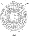
- FIG. 3 illustrates a stator assembly 60 for a gas turbine engine according to an example.
- the stator assembly 60 can be incorporated into a portion of the engines 10, 20, such as the fan sections 11, 22 and compressor sections 12, 24.
- the engines 10, 20, including blade and vane arrangements, and other systems such as land-based turbines may benefit from the teachings disclosed herein.
- the stator assembly 60 includes an array of stators or vanes 62 that are distributed about a longitudinal axis LX.
- the longitudinal axis LX can be collinear with or parallel to the engine longitudinal axis A of Figures 1 and 2 .
- the stator assembly 60 includes an inner (or first) endwall 64 and an outer (or second) endwall 66 circumferentially extending about the longitudinal axis LX to bound inner and outer diameters of a gas path GP.
- Each of the vanes 62 includes an airfoil section 62A extending in a spanwise or radial direction R between the inner and outer endwalls 64, 66.
- Each of the endwalls 64, 66 can have a generally elliptical or hoop-shaped geometry.
- each airfoil section 62A extends in an axial direction X between an airfoil leading edge 62LE and an airfoil trailing edge 62TE.
- Each airfoil section 62A extends in a circumferential or thickness direction T between pressure and suction sides 62P, 62S ( Figures 3 and 5 ).
- the rotor assembly 67 includes rotors 68 each carrying an array of blades 69 that extend into the gas path GP.
- the blades 69 are arranged into at least an upstream (or first) blade row 69-1 and a downstream (or second) blade row 69-2 relative to a general direction of flow in the gas path GP.
- the rotors 68 and blades 69 are rotatable about the longitudinal axis LX.
- the stator assembly 60 is positioned between, or is otherwise adjacent to, the first and second blade rows 69-1, 69-2 such that the upstream blade row 69-1 communicates flow in the gas path GP to the vanes 62 and such that the vanes 62 communicate the flow to the downstream blade row 69-2.
- the vanes 62 can serve as fan stators.
- the upstream blade row 69-1 and the row of vanes 62 of the stator assembly 60 can be incorporated into the fan sections 11, 22 and can comprise an axially forwardmost stage of the engines 10, 20 relative to the engine longitudinal axis A (see, e.g., stage 11A of Figure 1 ).
- the stator assembly 60 is incorporated into downstream fan or compressor stage(s) of the engines 10, 20.
- the vanes 62 are axially forward of the downstream blade row 69-2 such that the vanes 62 and blade row 69-2 can comprise adjacent stages of a section of the engine 10, 20.
- the inner endwall 64 includes a radially facing surface 70.
- the outer endwall 66 includes a radially facing surface 72 that is radially opposed to the radially facing surface 70 of the inner endwall 64 to radially bound the gas path GP (see also Figure 3 ).
- the radially facing surfaces 70, 72 have a major component that extends generally parallel to the longitudinal axis LX.
- the radially facing surfaces 70, 72 are axially sloped, converge or are otherwise dimensioned to converge in the axial direction X relative to the longitudinal axis LX to define a converging portion 78 of the gas path GP, including at the airfoil trailing edge 62LE relative to the airfoil leading edge 62TE.
- the converging portion 78 is dimensioned such that a cross-sectional area of the gas path GP at the airfoil leading edges 62LE is greater than a cross-sectional area of the gas path GP at the airfoil trailing edges 62TE.
- the cross-sectional area of the gas path GP at the airfoil trailing edges 62TE is less than 95% of the cross-sectional area of the gas path GP at the airfoil leading edges 62LE.
- Both of the radially facing surfaces 70, 72 can be axially sloped in the axial direction X between the airfoil leading and trailing edges 62LE, 62TE to define the converging portion 78.
- each vane 62 can be integrally formed with the inner and/or outer endwalls 64, 66.
- the airfoil section 62A and inner and/or outer endwalls 64, 66 are separate and distinct components that are mounted to or otherwise fixedly secured to each other.
- the endwalls 64, 66 are segmented such that the endwalls 64, 66 extend in the circumferential direction T between opposed mate faces 65 (shown in dashed lines in Figure 5 for illustrative purposes).
- At least one of the radially facing surfaces 70, 72 can be contoured to direct or orient flow in a predefined direction along the gas path GP.
- the radially facing surface 72 of the outer endwall 66 includes an axisymmetric contour 74 that bounds or otherwise defines the gas path GP.
- the contour 74 can be defined along the converging portion 78 of the gas path GP.
- axisymmetric contour means a contour that is axisymmetric relative to a respective axis (e.g., engine centerline axis) and excludes minor interruptions and manufacturing imperfections in the surface and filleting at a base of the respective airfoil.
- An axial position of the contour 74 can be defined relative to expected aerodynamic loading on the airfoil sections 62A.
- the axisymmetric contour 74 is at least partially swept in the circumferential direction T about the longitudinal axis LX (also shown in dashed lines in Figure 3 for illustrative purposes).
- the contour 74 is at least partially swept in the circumferential direction T from the pressure and suction sides 62P, 62S of the airfoil sections 62A.
- the contour 74 includes a plurality of sections 76 that extend between the pressure and suction sides 62P, 62S of adjacent airfoil sections 62A such that the contour 74 is swept in the circumferential direction T along the outer endwall 66 between the pressure and suction sides 62P, 62S of adjacent airfoils 62A and between each of the vanes 62 to bound the converging portion 78 of the gas path GP.
- the contour 74 is swept in the circumferential direction T between the pressure and suction sides 62P, 62S and respective ones of the mate faces 65.
- the axisymmetric contour 74 is a depression in the radially facing surface 72 extends inwardly from a reference plane RF (shown in dashed lines in Figure 4 ).
- the reference plane RF extends between junctions of the leading and trailing edges 62LE, 62TE and the outer endwall 66.
- the contour 74 has an arcuate, concave cross-sectional geometry that is circumferentially swept about the longitudinal axis LX to define an annular trench or groove in the outer endwall 66.
- the contour 74 can reduce a circumferential velocity of flow in the gas path GP, which can reduce aerodynamic loading on the airfoil sections 62A and increase loading on the endwall 66 adjacent the pressure side 62P of the airfoil section 62A to turn the flow without a net increase in loss and exit angle deviation.
- Figure 6 illustrates a stator assembly 160 including an endwall contour according to an example.
- like reference numerals designate like elements where appropriate and reference numerals with the addition of one-hundred or multiples thereof designate modified elements that are understood to incorporate the same features and benefits of the corresponding original elements.
- a stator or vane 162 includes an airfoil section 162A extending in a radial direction R from an endwall 166.
- a radially facing surface 172 of endwall 166 includes an axisymmetric contour 174 having an arcuate cross sectional geometry.
- the arcuate cross sectional geometry includes an apex A1 that is skewed in an axial direction X toward one of the airfoil leading and trailing edges 162LE, 162TE.
- the apex A1 is skewed towards the airfoil leading edge 162LE.
- contour 274 has an arcuate cross sectional geometry and is dimensioned such that apex A1 is skewed in an axial direction X towards an airfoil trailing edge 262TE.
- Figure 8 illustrates a stator assembly 360 including an endwall contour according to an example.
- axisymmetric contour 374 is a protrusion that extends outwardly from radially facing surface 372 and into gas path GP.
- the axisymmetric contour 374 has an arcuate, convex cross-sectional geometry defining an apex A1 that is radially outward of reference plane RF.
- the apex A1 can be skewed towards airfoil trailing edge 362TE, as illustrated in Figure 8 , or towards airfoil leading edge 362LE.
- the axisymmetric contours disclosed herein can include complex and other cross sectional geometries.
- Figure 9 illustrates a stator assembly 460 including an endwall contour according to an example.
- a radially facing surface 472 of endwall 466 includes an axisymmetric contour 474 having a sinusoidal cross sectional geometry.
- the sinusoidal cross sectional geometry includes a concave portion 474-1 and a convex portion 474-2 defining apexes A1, A2, respectively.
- the concave portion 474-1 extends inwardly from radially facing surface 472 with respect to a radial direction R.
- the convex portion 474-2 extends outwardly from the radially facing surface 472 with respect to the radially direction R.
- the concave portion 474-1 is defined between airfoil leading edge 462LE and the convex portion 474-2 with respect to an axial direction X.
- the convex portion 474-2 can reduce aerodynamic loading on the downstream blade row(s).
- the contours 74/174/274/374/474 disclosed herein can be utilized to change a radius of flow from upstream blades that may operate at relatively high Mach numbers. The change in radius can reduce swirl and secondary flow losses in the respective gas path.
- the contours 74/174/274/374/474 can be utilized to reduce peak Mach numbers and aerodynamic loading on the adjacent airfoil sections and downstream blade rows.
- the contours 74/174/274/374/474 disclosed herein primarily refer to an outer endwall, it should be appreciated that any of the contours 74/174/274/374/474 can be utilized for an inner endwall in view of the teachings disclosed herein.
Landscapes
- Engineering & Computer Science (AREA)
- Mechanical Engineering (AREA)
- General Engineering & Computer Science (AREA)
- Physics & Mathematics (AREA)
- Fluid Mechanics (AREA)
- Structures Of Non-Positive Displacement Pumps (AREA)
- Turbine Rotor Nozzle Sealing (AREA)
Description
- This disclosure relates to gas paths of a gas turbine engine, including endwalls that bound the gas paths.
- Gas turbine engines can include a fan section having a fan for propulsion air and to cool components. The fan also delivers air into a core engine where it is compressed. The compressed air is then delivered into a combustion section, where it is mixed with fuel and ignited. The combustion gas expands downstream over and drives turbine blades. Static vanes are positioned adjacent to the turbine blades to control the flow of the products of combustion.
- The fan or compressor sections may include one or more rows of vanes that are dimensioned to change an orientation of airflow in a gas path from an upstream blade row to prepare the airflow for delivery to a downstream blade row.
-
US 5 397 215 A discloses a vane for a gas turbine engine according to the preamble of claim 1. -
US 7 011 495 B2 discloses a turbomachine with increased rotor-stator ratio. -
US 2012/315136 A1 discloses an inner peripheral surface shape of a casing of an axial-flow compressor. -
WO 2016/032506 A1 discloses a controlled convergence compressor flowpath for a gas turbine engine. - The present invention provides a vane for a gas turbine engine as set forth in claim 1.
- Embodiments of the disclosure are set forth in the dependent claims.
- The various features and advantages of this disclosure will become apparent to those skilled in the art from the following detailed description. The drawings that accompany the detailed description can be briefly described as follows.
-
-
Figure 1 illustrates an example turbine engine. -
Figure 2 illustrates a turbine engine according to another example. -
Figure 3 illustrates an exemplary stator assembly. -
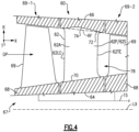
Figure 4 illustrates the stator assembly taken along line 4-4 ofFigure 3 . -
Figure 5 illustrates the stator assembly taken along line 5-5 ofFigure 3 . -
Figure 6 illustrates a stator assembly including an endwall contour outside the wording of the claims. -
Figure 7 illustrates a stator assembly including an endwall contour outside the wording of the claims. -
Figure 8 illustrates a stator assembly including an endwall contour outside the wording of the claims. -
Figure 9 illustrates a stator assembly including an endwall contour according to another example. - Referring to
Figure 1 , agas turbine engine 10 includes afan section 11, acompressor section 12, acombustor section 13, and aturbine section 14. Theturbine section 14 is rotationally coupled to thefan section 11 andcompressor section 12 with at least oneshaft 15. Air entering into thefan section 11 is initially compressed and fed to thecompressor section 12. In thecompressor section 12, the incoming air from thefan section 11 is further compressed and communicated to thecombustor section 13. In thecombustor section 13, the compressed air is mixed with gas and ignited to generate a hot exhaust stream E. The hot exhaust stream E is expanded through theturbine section 14 to drive thefan section 11 and thecompressor section 12. The exhaust gasses E flow from theturbine section 14 through anexhaust liner assembly 18. -
Figure 2 schematically illustrates agas turbine engine 20. Thegas turbine engine 20 is disclosed herein as a two-spool turbofan that generally incorporates afan section 22, acompressor section 24, a combustor section 26 and aturbine section 28. Thefan section 22 drives air along a bypass flow path B in a bypass duct defined within anacelle 15, and also drives air along a core flow path C for compression and communication into the combustor section 26 then expansion through theturbine section 28. Although depicted as a two-spool turbofan gas turbine engine in the disclosed non-limiting embodiment, it should be understood that the concepts described herein are not limited to use with two-spool turbofans as the teachings may be applied to other types of turbine engines including three-spool architectures. - The
exemplary engine 20 generally includes alow speed spool 30 and ahigh speed spool 32 mounted for rotation about an engine central longitudinal axis A relative to an enginestatic structure 36 viaseveral bearing systems 38. It should be understood thatvarious bearing systems 38 at various locations may alternatively or additionally be provided, and the location ofbearing systems 38 may be varied as appropriate to the application. - The
low speed spool 30 generally includes aninner shaft 40 that interconnects, a first (or low) pressure compressor 44 and a first (or low)pressure turbine 46. Theinner shaft 40 is connected to thefan 42 through a speed change mechanism, which in exemplarygas turbine engine 20 is illustrated as a gearedarchitecture 48 to drive afan 42 at a lower speed than thelow speed spool 30. Thehigh speed spool 32 includes anouter shaft 50 that interconnects a second (or high)pressure compressor 52 and a second (or high)pressure turbine 54. Acombustor 56 is arranged inexemplary gas turbine 20 between thehigh pressure compressor 52 and thehigh pressure turbine 54. Amid-turbine frame 57 of the enginestatic structure 36 may be arranged generally between thehigh pressure turbine 54 and thelow pressure turbine 46. Themid-turbine frame 57 further supports bearingsystems 38 in theturbine section 28. Theinner shaft 40 and theouter shaft 50 are concentric and rotate viabearing systems 38 about the engine central longitudinal axis A which is collinear with their longitudinal axes. - The core airflow is compressed by the low pressure compressor 44 then the
high pressure compressor 52, mixed and burned with fuel in thecombustor 56, then expanded over thehigh pressure turbine 54 andlow pressure turbine 46. Themid-turbine frame 57 includesairfoils 59 which are in the core airflow path C. Theturbines low speed spool 30 andhigh speed spool 32 in response to the expansion. It will be appreciated that each of the positions of thefan section 22,compressor section 24, combustor section 26,turbine section 28, and fandrive gear system 48 may be varied. For example,gear system 48 may be located aft of the low pressure compressor, or aft of the combustor section 26 or even aft ofturbine section 28, andfan 42 may be positioned forward or aft of the location ofgear system 48. - The
engine 20 in one example is a high-bypass geared aircraft engine. In a further example, theengine 20 bypass ratio is greater than about six, with an example embodiment being greater than about ten, the gearedarchitecture 48 is an epicyclic gear train, such as a planetary gear system or other gear system, with a gear reduction ratio of greater than about 2.3 and thelow pressure turbine 46 has a pressure ratio that is greater than about five. In one disclosed embodiment, theengine 20 bypass ratio is greater than about ten, the fan diameter is significantly larger than that of the low pressure compressor 44, and thelow pressure turbine 46 has a pressure ratio that is greater than about five.Low pressure turbine 46 pressure ratio is pressure measured prior to inlet oflow pressure turbine 46 as related to the pressure at the outlet of thelow pressure turbine 46 prior to an exhaust nozzle. The gearedarchitecture 48 may be an epicycle gear train, such as a planetary gear system or other gear system, with a gear reduction ratio of greater than about 2.3:1 and less than about 5:1. It should be understood, however, that the above parameters are only exemplary of one embodiment of a geared architecture engine and that the present invention is applicable to other gas turbine engines including direct drive turbofans. - A significant amount of thrust is provided by the bypass flow B due to the high bypass ratio. The
fan section 22 of theengine 20 is designed for a particular flight condition -- typically cruise at about 0.8 Mach and about 35,000 feet (10,668 meters). The flight condition of 0.8 Mach and 35,000 ft (10,668 meters), with the engine at its best fuel consumption - also known as "bucket cruise Thrust Specific Fuel Consumption ('TSFC')" - is the industry standard parameter of lbm of fuel being burned divided by lbf of thrust the engine produces at that minimum point. "Low fan pressure ratio" is the pressure ratio across the fan blade alone, without a Fan Exit Guide Vane ("FEGV") system. The low fan pressure ratio as disclosed herein according to one non-limiting embodiment is less than about 1.45. "Low corrected fan tip speed" is the actual fan tip speed in ft/sec divided by an industry standard temperature correction of [(Tram °R) / (518.7 °R)]0.5(where °R = K × 9/5). The "Low corrected fan tip speed" as disclosed herein according to one non-limiting embodiment is less than about 1150 ft / second (350.5 meters/second). -
Figure 3 illustrates astator assembly 60 for a gas turbine engine according to an example. Thestator assembly 60 can be incorporated into a portion of theengines fan sections compressor sections engines - The
stator assembly 60 includes an array of stators orvanes 62 that are distributed about a longitudinal axis LX. The longitudinal axis LX can be collinear with or parallel to the engine longitudinal axis A ofFigures 1 and2 . Thestator assembly 60 includes an inner (or first) endwall 64 and an outer (or second) endwall 66 circumferentially extending about the longitudinal axis LX to bound inner and outer diameters of a gas path GP. Each of thevanes 62 includes anairfoil section 62A extending in a spanwise or radial direction R between the inner andouter endwalls endwalls - Referring to
Figure 4 , with continuing reference toFigure 3 , thestator assembly 60 is shown adjacent to arotor assembly 67. Eachairfoil section 62A extends in an axial direction X between an airfoil leading edge 62LE and an airfoil trailing edge 62TE. Eachairfoil section 62A extends in a circumferential or thickness direction T between pressure andsuction sides Figures 3 and5 ). - The
rotor assembly 67 includesrotors 68 each carrying an array ofblades 69 that extend into the gas path GP. In the illustrative example ofFigure 4 , theblades 69 are arranged into at least an upstream (or first) blade row 69-1 and a downstream (or second) blade row 69-2 relative to a general direction of flow in the gas path GP. Therotors 68 andblades 69 are rotatable about the longitudinal axis LX. Thestator assembly 60 is positioned between, or is otherwise adjacent to, the first and second blade rows 69-1, 69-2 such that the upstream blade row 69-1 communicates flow in the gas path GP to thevanes 62 and such that thevanes 62 communicate the flow to the downstream blade row 69-2. - The
vanes 62 can serve as fan stators. For example, the upstream blade row 69-1 and the row ofvanes 62 of thestator assembly 60 can be incorporated into thefan sections engines stage 11A ofFigure 1 ). In other examples, thestator assembly 60 is incorporated into downstream fan or compressor stage(s) of theengines vanes 62 are axially forward of the downstream blade row 69-2 such that thevanes 62 and blade row 69-2 can comprise adjacent stages of a section of theengine - The
inner endwall 64 includes aradially facing surface 70. Theouter endwall 66 includes aradially facing surface 72 that is radially opposed to theradially facing surface 70 of theinner endwall 64 to radially bound the gas path GP (see alsoFigure 3 ). Theradially facing surfaces - In the illustrative example of
Figure 4 , theradially facing surfaces portion 78 of the gas path GP, including at the airfoil trailing edge 62LE relative to the airfoil leading edge 62TE. The convergingportion 78 is dimensioned such that a cross-sectional area of the gas path GP at the airfoil leading edges 62LE is greater than a cross-sectional area of the gas path GP at the airfoil trailing edges 62TE. In examples, the cross-sectional area of the gas path GP at the airfoil trailing edges 62TE is less than 95% of the cross-sectional area of the gas path GP at the airfoil leading edges 62LE. Both of theradially facing surfaces portion 78. - The
airfoil section 62A of eachvane 62 can be integrally formed with the inner and/orouter endwalls airfoil section 62A and inner and/orouter endwalls endwalls endwalls Figure 5 for illustrative purposes). - At least one of the
radially facing surfaces Figure 4 , theradially facing surface 72 of theouter endwall 66 includes anaxisymmetric contour 74 that bounds or otherwise defines the gas path GP. Thecontour 74 can be defined along the convergingportion 78 of the gas path GP. For the purposes of this disclosure, the term "axisymmetric contour" means a contour that is axisymmetric relative to a respective axis (e.g., engine centerline axis) and excludes minor interruptions and manufacturing imperfections in the surface and filleting at a base of the respective airfoil. An axial position of thecontour 74 can be defined relative to expected aerodynamic loading on theairfoil sections 62A. - Referring to
Figure 5 , with continuing reference toFigure 4 , theaxisymmetric contour 74 is at least partially swept in the circumferential direction T about the longitudinal axis LX (also shown in dashed lines inFigure 3 for illustrative purposes). Thecontour 74 is at least partially swept in the circumferential direction T from the pressure andsuction sides airfoil sections 62A. In the illustrative example ofFigure 5 , thecontour 74 includes a plurality ofsections 76 that extend between the pressure andsuction sides adjacent airfoil sections 62A such that thecontour 74 is swept in the circumferential direction T along theouter endwall 66 between the pressure andsuction sides adjacent airfoils 62A and between each of thevanes 62 to bound the convergingportion 78 of the gas path GP. In examples, including mate faces 65, thecontour 74 is swept in the circumferential direction T between the pressure andsuction sides - In the illustrative example of
Figure 5 , theaxisymmetric contour 74 is a depression in theradially facing surface 72 extends inwardly from a reference plane RF (shown in dashed lines inFigure 4 ). The reference plane RF extends between junctions of the leading and trailing edges 62LE, 62TE and theouter endwall 66. Thecontour 74 has an arcuate, concave cross-sectional geometry that is circumferentially swept about the longitudinal axis LX to define an annular trench or groove in theouter endwall 66. Thecontour 74 can reduce a circumferential velocity of flow in the gas path GP, which can reduce aerodynamic loading on theairfoil sections 62A and increase loading on theendwall 66 adjacent thepressure side 62P of theairfoil section 62A to turn the flow without a net increase in loss and exit angle deviation. -
Figure 6 illustrates astator assembly 160 including an endwall contour according to an example. In this disclosure, like reference numerals designate like elements where appropriate and reference numerals with the addition of one-hundred or multiples thereof designate modified elements that are understood to incorporate the same features and benefits of the corresponding original elements. - A stator or
vane 162 includes anairfoil section 162A extending in a radial direction R from anendwall 166. Aradially facing surface 172 ofendwall 166 includes anaxisymmetric contour 174 having an arcuate cross sectional geometry. The arcuate cross sectional geometry includes an apex A1 that is skewed in an axial direction X toward one of the airfoil leading and trailing edges 162LE, 162TE. In the illustrative example ofFigure 6 , the apex A1 is skewed towards the airfoil leading edge 162LE. In the illustrative example ofFigure 7 ,contour 274 has an arcuate cross sectional geometry and is dimensioned such that apex A1 is skewed in an axial direction X towards an airfoil trailing edge 262TE. -
Figure 8 illustrates astator assembly 360 including an endwall contour according to an example. In the illustrative example ofFigure 8 ,axisymmetric contour 374 is a protrusion that extends outwardly from radially facingsurface 372 and into gas path GP. Theaxisymmetric contour 374 has an arcuate, convex cross-sectional geometry defining an apex A1 that is radially outward of reference plane RF. The apex A1 can be skewed towards airfoil trailing edge 362TE, as illustrated inFigure 8 , or towards airfoil leading edge 362LE. It should be appreciated that the axisymmetric contours disclosed herein can include complex and other cross sectional geometries. -
Figure 9 illustrates astator assembly 460 including an endwall contour according to an example. Aradially facing surface 472 ofendwall 466 includes anaxisymmetric contour 474 having a sinusoidal cross sectional geometry. The sinusoidal cross sectional geometry includes a concave portion 474-1 and a convex portion 474-2 defining apexes A1, A2, respectively. The concave portion 474-1 extends inwardly from radially facingsurface 472 with respect to a radial direction R. The convex portion 474-2 extends outwardly from theradially facing surface 472 with respect to the radially direction R. In the illustrative example ofFigure 9 , the concave portion 474-1 is defined between airfoil leading edge 462LE and the convex portion 474-2 with respect to an axial direction X. The convex portion 474-2 can reduce aerodynamic loading on the downstream blade row(s). - The
contours 74/174/274/374/474 disclosed herein can be utilized to change a radius of flow from upstream blades that may operate at relatively high Mach numbers. The change in radius can reduce swirl and secondary flow losses in the respective gas path. Thecontours 74/174/274/374/474 can be utilized to reduce peak Mach numbers and aerodynamic loading on the adjacent airfoil sections and downstream blade rows. Although thecontours 74/174/274/374/474 disclosed herein primarily refer to an outer endwall, it should be appreciated that any of thecontours 74/174/274/374/474 can be utilized for an inner endwall in view of the teachings disclosed herein. - It should be understood that relative positional terms such as "forward," "aft," "upper," "lower," "above," "below," and the like are with reference to the normal operational attitude of the vehicle and should not be considered otherwise limiting.
- Although the different examples have the specific components shown in the illustrations, embodiments of this disclosure are not limited to those particular combinations. It is possible to use some of the components or features from one of the examples in combination with features or components from another one of the examples.
- Although particular step sequences are shown, described, and claimed, it should be understood that steps may be performed in any order, separated or combined unless otherwise indicated and will still benefit from the present disclosure.
- The foregoing description is exemplary rather than defined by the limitations within. Various non-limiting embodiments are disclosed herein, however, one of ordinary skill in the art would recognize that various modifications and variations in light of the above teachings will fall within the scope of the appended claims. It is therefore to be understood that within the scope of the appended claims, the disclosure may be practiced other than as specifically described. For that reason the appended claims should be studied to determine true scope and content.
Claims (7)
- A vane (62; 162; 262; 362; 462) for a gas turbine engine (10; 20) comprising:first and second endwalls (66, 64) each including a radially facing surface (70, 72) that bounds a gas path (GP); andan airfoil section (62A) extending in a radial direction (R) between the first and second endwalls (66, 64), extending in an axial direction (X) between an airfoil leading edge (62LE) and an airfoil trailing edge (62TE), and extending in a circumferential direction between pressure and suction sides (62P, 62S), wherein the radially facing surface (70, 72) of each of the first and second endwalls (66, 64) is axially sloped such that the gas (GP) path converges in the axial direction (X) between the airfoil leading and trailing edges (62LE, 62TE), and the first endwall (66, 64) includes an axisymmetric contour (74) extending in the circumferential direction between the pressure and suction sides (62PS, 62SS), wherein the first endwall (66, 64) extends in the circumferential direction between opposed mate faces (65),characterised in that:the axisymmetric contour (74) is swept in the circumferential direction between the pressure and suction sides (62PS, 62SS) and respective ones of the opposed mate faces (65); andthe axisymmetric contour (474) has a sinusoidal cross sectional geometry.
- The vane as recited in claim 1, wherein the sinusoidal cross sectional geometry includes a concave portion (474-1) and a convex portion (474-2), the concave portion (474-1) extends inwardly from the radially facing surface (472) with respect to the radial direction (R), the convex portion (474-2) extends outwardly from the radially facing surface (472) with respect to the radially direction (R), and the concave portion (474-1) is defined between the airfoil leading edge (462-LE) and the convex portion (474-2) with respect to the axial direction (X).
- The vane as recited in any preceding claim, wherein the vane (62...462) is a fan stator (62...462).
- A section for a gas turbine engine (10; 20) comprising:a rotor (68) carrying an array of blades (69) that extend into a gas path (GP), the rotor (68) rotatable about a longitudinal axis (LX); andan array of vanes (62; 162; 262; 362; 462) distributed about the longitudinal axis (LX), each vane (62; 162; 262; 362; 462) as set forth in claim 1.
- The section as recited in claim 4, wherein the array of vanes (62...462) are axially forward of the array of blades (62) relative to the longitudinal axis (LX) such that the array of vanes (62...462) and the array of blades (62) comprise adjacent stages of the section.
- A gas turbine engine (10; 20) comprising:a fan section;a combustor in fluid communication with the fan section; anda turbine section rotationally coupled to the fan section, wherein the fan section includes a row of blades (69) rotatable about an engine longitudinal axis (LE), a stator assembly (60) including a row of vanes (62; 162; 262; 362; 462) adjacent the row of blades (69), each of the vanes (62...462) as set forth in claim 1.
- The gas turbine engine as recited in claim 6, wherein the row of blades (69) and the row of vanes (62...462) comprise an axially forwardmost stage of the gas turbine engine (10; 20) relative to the engine longitudinal axis (LE).
Applications Claiming Priority (1)
| Application Number | Priority Date | Filing Date | Title |
|---|---|---|---|
| US16/263,063 US10920599B2 (en) | 2019-01-31 | 2019-01-31 | Contoured endwall for a gas turbine engine |
Publications (2)
| Publication Number | Publication Date |
|---|---|
| EP3690189A1 EP3690189A1 (en) | 2020-08-05 |
| EP3690189B1 true EP3690189B1 (en) | 2023-04-05 |
Family
ID=69467336
Family Applications (1)
| Application Number | Title | Priority Date | Filing Date |
|---|---|---|---|
| EP20155024.1A Active EP3690189B1 (en) | 2019-01-31 | 2020-01-31 | Contoured endwall for a gas turbine engine |
Country Status (2)
| Country | Link |
|---|---|
| US (1) | US10920599B2 (en) |
| EP (1) | EP3690189B1 (en) |
Families Citing this family (5)
| Publication number | Priority date | Publication date | Assignee | Title |
|---|---|---|---|---|
| DE102020209586A1 (en) | 2020-07-30 | 2022-02-03 | MTU Aero Engines AG | GUIDE VANE FOR A FLOW MACHINE |
| US12196110B2 (en) | 2022-03-04 | 2025-01-14 | MTU Aero Engines AG | Blisk for a gas turbine |
| DE102022117268A1 (en) * | 2022-07-12 | 2024-01-18 | MTU Aero Engines AG | Rotor blade and rotor blade arrangement for a turbomachine |
| US20250297571A1 (en) * | 2024-03-19 | 2025-09-25 | General Electric Company | System and apparatus for reducing bow waves in gas turbine engines |
| US12442304B1 (en) | 2025-03-12 | 2025-10-14 | General Electric Company | Gas turbine engine with bow wave mitigation |
Citations (5)
| Publication number | Priority date | Publication date | Assignee | Title |
|---|---|---|---|---|
| US5466123A (en) | 1993-08-20 | 1995-11-14 | Rolls-Royce Plc | Gas turbine engine turbine |
| US20100172749A1 (en) | 2007-03-29 | 2010-07-08 | Mitsuhashi Katsunori | Wall of turbo machine and turbo machine |
| WO2018004583A1 (en) | 2016-06-30 | 2018-01-04 | Siemens Aktiengesellschaft | Stator vane assembly having mate face seal with cooling holes |
| EP3683403A1 (en) | 2013-03-12 | 2020-07-22 | Pratt & Whitney Canada Corp. | Compressor stator |
| EP3090143B1 (en) | 2013-12-09 | 2021-03-10 | United Technologies Corporation | Array of components in a gas turbine engine |
Family Cites Families (13)
| Publication number | Priority date | Publication date | Assignee | Title |
|---|---|---|---|---|
| US5397215A (en) | 1993-06-14 | 1995-03-14 | United Technologies Corporation | Flow directing assembly for the compression section of a rotary machine |
| US5653580A (en) * | 1995-03-06 | 1997-08-05 | Solar Turbines Incorporated | Nozzle and shroud assembly mounting structure |
| DE19650656C1 (en) | 1996-12-06 | 1998-06-10 | Mtu Muenchen Gmbh | Turbo machine with transonic compressor stage |
| DE10233033A1 (en) | 2002-07-20 | 2004-01-29 | Rolls-Royce Deutschland Ltd & Co Kg | Fluid flow machine with excessive rotor-stator contraction ratio |
| US8734096B2 (en) * | 2010-07-26 | 2014-05-27 | Snecma | Optimized aerodynamic profile for a turbine vane, in particular for a nozzle of the second stage of a turbine |
| US20120051930A1 (en) * | 2010-08-31 | 2012-03-01 | General Electric Company | Shrouded turbine blade with contoured platform and axial dovetail |
| EP2458148A1 (en) | 2010-11-25 | 2012-05-30 | Siemens Aktiengesellschaft | Turbo-machine component with a surface for cooling |
| DE102011076804B4 (en) * | 2011-05-31 | 2019-04-25 | Honda Motor Co., Ltd. | Inner peripheral surface shape of a fan housing of an axial compressor |
| WO2015077067A1 (en) | 2013-11-21 | 2015-05-28 | United Technologies Corporation | Axisymmetric offset of three-dimensional contoured endwalls |
| CN106574505B (en) | 2014-08-29 | 2018-06-19 | 西门子公司 | For the controlled convergence compressor flow path of gas-turbine unit |
| ES2743501T3 (en) | 2014-12-12 | 2020-02-19 | MTU Aero Engines AG | Exit guide grid and dual flow turbojet with an exit guide grid |
| US10125623B2 (en) | 2016-02-09 | 2018-11-13 | General Electric Company | Turbine nozzle profile |
| WO2018219611A1 (en) | 2017-06-01 | 2018-12-06 | Siemens Aktiengesellschaft | Compressor stator vane for axial compressors having a corrugated tip contour |
-
2019
- 2019-01-31 US US16/263,063 patent/US10920599B2/en active Active
-
2020
- 2020-01-31 EP EP20155024.1A patent/EP3690189B1/en active Active
Patent Citations (5)
| Publication number | Priority date | Publication date | Assignee | Title |
|---|---|---|---|---|
| US5466123A (en) | 1993-08-20 | 1995-11-14 | Rolls-Royce Plc | Gas turbine engine turbine |
| US20100172749A1 (en) | 2007-03-29 | 2010-07-08 | Mitsuhashi Katsunori | Wall of turbo machine and turbo machine |
| EP3683403A1 (en) | 2013-03-12 | 2020-07-22 | Pratt & Whitney Canada Corp. | Compressor stator |
| EP3090143B1 (en) | 2013-12-09 | 2021-03-10 | United Technologies Corporation | Array of components in a gas turbine engine |
| WO2018004583A1 (en) | 2016-06-30 | 2018-01-04 | Siemens Aktiengesellschaft | Stator vane assembly having mate face seal with cooling holes |
Non-Patent Citations (4)
| Title |
|---|
| "The Jet engine", 1 January 1986, ROLLS-ROYCE PLC , ISBN: 978-0-902121-23-2, article ANONYMOUS: "3: Compressors", pages: 19 - 34, XP093153365 |
| "The Jet engine", 1 January 1986, ROLLS-ROYCE PLC , ISBN: 978-0-902121-23-2, article ANONYMOUS: "5: Turbines ", pages: 45 - 58, XP093153366 |
| ANONYMOUS: "Turboréacteur", WIKIPÉDIA, 7 December 2023 (2023-12-07), pages 1 - 33, XP093153372, Retrieved from the Internet <URL:https://fr.wikipedia.org/w/index.php?title=Turboréacteur&oldid=210331662> |
| OWENS R., HASEL K., MAPES D.: "Ultra high bypass turbofan technologies for the twenty-first century", 26TH JOINT PROPULSION CONFERENCE, AMERICAN INSTITUTE OF AERONAUTICS AND ASTRONAUTICS, 16 July 1990 (1990-07-16), pages 1 - 9, XP093270949 |
Also Published As
| Publication number | Publication date |
|---|---|
| EP3690189A1 (en) | 2020-08-05 |
| US20200248572A1 (en) | 2020-08-06 |
| US10920599B2 (en) | 2021-02-16 |
Similar Documents
| Publication | Publication Date | Title |
|---|---|---|
| EP3613950B1 (en) | Blade outer air seal formed of laminate and having radial support hooks | |
| EP3690189B1 (en) | Contoured endwall for a gas turbine engine | |
| US11421558B2 (en) | Gas turbine engine component | |
| EP3064711B1 (en) | Component for a gas turbine engine, corresponding gas turbine engine and method of forming an airfoil | |
| EP3071796B1 (en) | Gas turbine engine variable area vane with contoured endwalls | |
| WO2014011246A2 (en) | Integrated inlet vane and strut | |
| EP3587740B1 (en) | Seal assembly for a gas turbine engine and method of assembling | |
| EP3112606B1 (en) | A seal for a gas turbine engine | |
| EP3009616B1 (en) | Gas turbine component with platform cooling | |
| EP3094823B1 (en) | Gas turbine engine component and corresponding gas turbine engine | |
| EP2998509B1 (en) | Endwall contouring for airfoil rows with varying airfoil geometries | |
| EP3461993B1 (en) | Gas turbine engine blade | |
| EP3623585B1 (en) | Pressure side cover for a variable camber vane assembly for a compressor of a gas turbine engine | |
| EP3467260B1 (en) | Turbine blade with bowed tip | |
| EP3450685B1 (en) | Gas turbine engine component | |
| EP3623587B1 (en) | Airfoil assembly for a gas turbine engine | |
| EP3039247B1 (en) | Gas turbine engine airfoil crossover and pedestal rib cooling arrangement | |
| EP3470627B1 (en) | Gas turbine engine airfoil | |
| EP3477055B1 (en) | Component for a gas turbine engine comprising an airfoil | |
| US10378363B2 (en) | Resupply hole of cooling air into gas turbine blade serpentine passage | |
| EP2885503B1 (en) | Integrally bladed rotor |
Legal Events
| Date | Code | Title | Description |
|---|---|---|---|
| PUAI | Public reference made under article 153(3) epc to a published international application that has entered the european phase |
Free format text: ORIGINAL CODE: 0009012 |
|
| STAA | Information on the status of an ep patent application or granted ep patent |
Free format text: STATUS: THE APPLICATION HAS BEEN PUBLISHED |
|
| AK | Designated contracting states |
Kind code of ref document: A1 Designated state(s): AL AT BE BG CH CY CZ DE DK EE ES FI FR GB GR HR HU IE IS IT LI LT LU LV MC MK MT NL NO PL PT RO RS SE SI SK SM TR |
|
| AX | Request for extension of the european patent |
Extension state: BA ME |
|
| RIN1 | Information on inventor provided before grant (corrected) |
Inventor name: ADHATE, ABHIR A. Inventor name: PRIOR, FRANK M. Inventor name: WAGNER, KALMAN V. |
|
| STAA | Information on the status of an ep patent application or granted ep patent |
Free format text: STATUS: REQUEST FOR EXAMINATION WAS MADE |
|
| 17P | Request for examination filed |
Effective date: 20210205 |
|
| RBV | Designated contracting states (corrected) |
Designated state(s): AL AT BE BG CH CY CZ DE DK EE ES FI FR GB GR HR HU IE IS IT LI LT LU LV MC MK MT NL NO PL PT RO RS SE SI SK SM TR |
|
| RAP1 | Party data changed (applicant data changed or rights of an application transferred) |
Owner name: RAYTHEON TECHNOLOGIES CORPORATION |
|
| GRAP | Despatch of communication of intention to grant a patent |
Free format text: ORIGINAL CODE: EPIDOSNIGR1 |
|
| STAA | Information on the status of an ep patent application or granted ep patent |
Free format text: STATUS: GRANT OF PATENT IS INTENDED |
|
| INTG | Intention to grant announced |
Effective date: 20221010 |
|
| RIN1 | Information on inventor provided before grant (corrected) |
Inventor name: WAGNER, KALMAN V. Inventor name: PRIOR, FRANK M. Inventor name: ADHATE, ABHIR A. |
|
| GRAS | Grant fee paid |
Free format text: ORIGINAL CODE: EPIDOSNIGR3 |
|
| GRAA | (expected) grant |
Free format text: ORIGINAL CODE: 0009210 |
|
| STAA | Information on the status of an ep patent application or granted ep patent |
Free format text: STATUS: THE PATENT HAS BEEN GRANTED |
|
| AK | Designated contracting states |
Kind code of ref document: B1 Designated state(s): AL AT BE BG CH CY CZ DE DK EE ES FI FR GB GR HR HU IE IS IT LI LT LU LV MC MK MT NL NO PL PT RO RS SE SI SK SM TR |
|
| REG | Reference to a national code |
Ref country code: GB Ref legal event code: FG4D |
|
| REG | Reference to a national code |
Ref country code: CH Ref legal event code: EP |
|
| REG | Reference to a national code |
Ref country code: AT Ref legal event code: REF Ref document number: 1558385 Country of ref document: AT Kind code of ref document: T Effective date: 20230415 |
|
| REG | Reference to a national code |
Ref country code: DE Ref legal event code: R096 Ref document number: 602020009336 Country of ref document: DE |
|
| REG | Reference to a national code |
Ref country code: IE Ref legal event code: FG4D |
|
| P01 | Opt-out of the competence of the unified patent court (upc) registered |
Effective date: 20230521 |
|
| REG | Reference to a national code |
Ref country code: LT Ref legal event code: MG9D |
|
| REG | Reference to a national code |
Ref country code: NL Ref legal event code: MP Effective date: 20230405 |
|
| REG | Reference to a national code |
Ref country code: AT Ref legal event code: MK05 Ref document number: 1558385 Country of ref document: AT Kind code of ref document: T Effective date: 20230405 |
|
| PG25 | Lapsed in a contracting state [announced via postgrant information from national office to epo] |
Ref country code: NL Free format text: LAPSE BECAUSE OF FAILURE TO SUBMIT A TRANSLATION OF THE DESCRIPTION OR TO PAY THE FEE WITHIN THE PRESCRIBED TIME-LIMIT Effective date: 20230405 |
|
| PG25 | Lapsed in a contracting state [announced via postgrant information from national office to epo] |
Ref country code: SE Free format text: LAPSE BECAUSE OF FAILURE TO SUBMIT A TRANSLATION OF THE DESCRIPTION OR TO PAY THE FEE WITHIN THE PRESCRIBED TIME-LIMIT Effective date: 20230405 Ref country code: PT Free format text: LAPSE BECAUSE OF FAILURE TO SUBMIT A TRANSLATION OF THE DESCRIPTION OR TO PAY THE FEE WITHIN THE PRESCRIBED TIME-LIMIT Effective date: 20230807 Ref country code: NO Free format text: LAPSE BECAUSE OF FAILURE TO SUBMIT A TRANSLATION OF THE DESCRIPTION OR TO PAY THE FEE WITHIN THE PRESCRIBED TIME-LIMIT Effective date: 20230705 Ref country code: ES Free format text: LAPSE BECAUSE OF FAILURE TO SUBMIT A TRANSLATION OF THE DESCRIPTION OR TO PAY THE FEE WITHIN THE PRESCRIBED TIME-LIMIT Effective date: 20230405 Ref country code: AT Free format text: LAPSE BECAUSE OF FAILURE TO SUBMIT A TRANSLATION OF THE DESCRIPTION OR TO PAY THE FEE WITHIN THE PRESCRIBED TIME-LIMIT Effective date: 20230405 |
|
| RAP4 | Party data changed (patent owner data changed or rights of a patent transferred) |
Owner name: RTX CORPORATION |
|
| PG25 | Lapsed in a contracting state [announced via postgrant information from national office to epo] |
Ref country code: RS Free format text: LAPSE BECAUSE OF FAILURE TO SUBMIT A TRANSLATION OF THE DESCRIPTION OR TO PAY THE FEE WITHIN THE PRESCRIBED TIME-LIMIT Effective date: 20230405 Ref country code: PL Free format text: LAPSE BECAUSE OF FAILURE TO SUBMIT A TRANSLATION OF THE DESCRIPTION OR TO PAY THE FEE WITHIN THE PRESCRIBED TIME-LIMIT Effective date: 20230405 Ref country code: LV Free format text: LAPSE BECAUSE OF FAILURE TO SUBMIT A TRANSLATION OF THE DESCRIPTION OR TO PAY THE FEE WITHIN THE PRESCRIBED TIME-LIMIT Effective date: 20230405 Ref country code: LT Free format text: LAPSE BECAUSE OF FAILURE TO SUBMIT A TRANSLATION OF THE DESCRIPTION OR TO PAY THE FEE WITHIN THE PRESCRIBED TIME-LIMIT Effective date: 20230405 Ref country code: IS Free format text: LAPSE BECAUSE OF FAILURE TO SUBMIT A TRANSLATION OF THE DESCRIPTION OR TO PAY THE FEE WITHIN THE PRESCRIBED TIME-LIMIT Effective date: 20230805 Ref country code: HR Free format text: LAPSE BECAUSE OF FAILURE TO SUBMIT A TRANSLATION OF THE DESCRIPTION OR TO PAY THE FEE WITHIN THE PRESCRIBED TIME-LIMIT Effective date: 20230405 Ref country code: GR Free format text: LAPSE BECAUSE OF FAILURE TO SUBMIT A TRANSLATION OF THE DESCRIPTION OR TO PAY THE FEE WITHIN THE PRESCRIBED TIME-LIMIT Effective date: 20230706 Ref country code: AL Free format text: LAPSE BECAUSE OF FAILURE TO SUBMIT A TRANSLATION OF THE DESCRIPTION OR TO PAY THE FEE WITHIN THE PRESCRIBED TIME-LIMIT Effective date: 20230405 |
|
| PG25 | Lapsed in a contracting state [announced via postgrant information from national office to epo] |
Ref country code: FI Free format text: LAPSE BECAUSE OF FAILURE TO SUBMIT A TRANSLATION OF THE DESCRIPTION OR TO PAY THE FEE WITHIN THE PRESCRIBED TIME-LIMIT Effective date: 20230405 |
|
| REG | Reference to a national code |
Ref country code: DE Ref legal event code: R026 Ref document number: 602020009336 Country of ref document: DE |
|
| PLBI | Opposition filed |
Free format text: ORIGINAL CODE: 0009260 |
|
| PG25 | Lapsed in a contracting state [announced via postgrant information from national office to epo] |
Ref country code: SK Free format text: LAPSE BECAUSE OF FAILURE TO SUBMIT A TRANSLATION OF THE DESCRIPTION OR TO PAY THE FEE WITHIN THE PRESCRIBED TIME-LIMIT Effective date: 20230405 |
|
| PLAX | Notice of opposition and request to file observation + time limit sent |
Free format text: ORIGINAL CODE: EPIDOSNOBS2 |
|
| PG25 | Lapsed in a contracting state [announced via postgrant information from national office to epo] |
Ref country code: SM Free format text: LAPSE BECAUSE OF FAILURE TO SUBMIT A TRANSLATION OF THE DESCRIPTION OR TO PAY THE FEE WITHIN THE PRESCRIBED TIME-LIMIT Effective date: 20230405 Ref country code: SK Free format text: LAPSE BECAUSE OF FAILURE TO SUBMIT A TRANSLATION OF THE DESCRIPTION OR TO PAY THE FEE WITHIN THE PRESCRIBED TIME-LIMIT Effective date: 20230405 Ref country code: RO Free format text: LAPSE BECAUSE OF FAILURE TO SUBMIT A TRANSLATION OF THE DESCRIPTION OR TO PAY THE FEE WITHIN THE PRESCRIBED TIME-LIMIT Effective date: 20230405 Ref country code: EE Free format text: LAPSE BECAUSE OF FAILURE TO SUBMIT A TRANSLATION OF THE DESCRIPTION OR TO PAY THE FEE WITHIN THE PRESCRIBED TIME-LIMIT Effective date: 20230405 Ref country code: DK Free format text: LAPSE BECAUSE OF FAILURE TO SUBMIT A TRANSLATION OF THE DESCRIPTION OR TO PAY THE FEE WITHIN THE PRESCRIBED TIME-LIMIT Effective date: 20230405 Ref country code: CZ Free format text: LAPSE BECAUSE OF FAILURE TO SUBMIT A TRANSLATION OF THE DESCRIPTION OR TO PAY THE FEE WITHIN THE PRESCRIBED TIME-LIMIT Effective date: 20230405 |
|
| 26 | Opposition filed |
Opponent name: SAFRAN AIRCRAFT ENGINES Effective date: 20240105 |
|
| PG25 | Lapsed in a contracting state [announced via postgrant information from national office to epo] |
Ref country code: SI Free format text: LAPSE BECAUSE OF FAILURE TO SUBMIT A TRANSLATION OF THE DESCRIPTION OR TO PAY THE FEE WITHIN THE PRESCRIBED TIME-LIMIT Effective date: 20230405 |
|
| PLBB | Reply of patent proprietor to notice(s) of opposition received |
Free format text: ORIGINAL CODE: EPIDOSNOBS3 |
|
| PG25 | Lapsed in a contracting state [announced via postgrant information from national office to epo] |
Ref country code: SI Free format text: LAPSE BECAUSE OF FAILURE TO SUBMIT A TRANSLATION OF THE DESCRIPTION OR TO PAY THE FEE WITHIN THE PRESCRIBED TIME-LIMIT Effective date: 20230405 Ref country code: IT Free format text: LAPSE BECAUSE OF FAILURE TO SUBMIT A TRANSLATION OF THE DESCRIPTION OR TO PAY THE FEE WITHIN THE PRESCRIBED TIME-LIMIT Effective date: 20230405 |
|
| PG25 | Lapsed in a contracting state [announced via postgrant information from national office to epo] |
Ref country code: MC Free format text: LAPSE BECAUSE OF FAILURE TO SUBMIT A TRANSLATION OF THE DESCRIPTION OR TO PAY THE FEE WITHIN THE PRESCRIBED TIME-LIMIT Effective date: 20230405 |
|
| PG25 | Lapsed in a contracting state [announced via postgrant information from national office to epo] |
Ref country code: MC Free format text: LAPSE BECAUSE OF FAILURE TO SUBMIT A TRANSLATION OF THE DESCRIPTION OR TO PAY THE FEE WITHIN THE PRESCRIBED TIME-LIMIT Effective date: 20230405 |
|
| REG | Reference to a national code |
Ref country code: CH Ref legal event code: PL |
|
| PG25 | Lapsed in a contracting state [announced via postgrant information from national office to epo] |
Ref country code: LU Free format text: LAPSE BECAUSE OF NON-PAYMENT OF DUE FEES Effective date: 20240131 |
|
| PG25 | Lapsed in a contracting state [announced via postgrant information from national office to epo] |
Ref country code: LU Free format text: LAPSE BECAUSE OF NON-PAYMENT OF DUE FEES Effective date: 20240131 |
|
| PG25 | Lapsed in a contracting state [announced via postgrant information from national office to epo] |
Ref country code: BE Free format text: LAPSE BECAUSE OF NON-PAYMENT OF DUE FEES Effective date: 20240131 |
|
| PG25 | Lapsed in a contracting state [announced via postgrant information from national office to epo] |
Ref country code: CH Free format text: LAPSE BECAUSE OF NON-PAYMENT OF DUE FEES Effective date: 20240131 |
|
| PG25 | Lapsed in a contracting state [announced via postgrant information from national office to epo] |
Ref country code: CH Free format text: LAPSE BECAUSE OF NON-PAYMENT OF DUE FEES Effective date: 20240131 Ref country code: BE Free format text: LAPSE BECAUSE OF NON-PAYMENT OF DUE FEES Effective date: 20240131 |
|
| REG | Reference to a national code |
Ref country code: BE Ref legal event code: MM Effective date: 20240131 |
|
| PG25 | Lapsed in a contracting state [announced via postgrant information from national office to epo] |
Ref country code: BG Free format text: LAPSE BECAUSE OF FAILURE TO SUBMIT A TRANSLATION OF THE DESCRIPTION OR TO PAY THE FEE WITHIN THE PRESCRIBED TIME-LIMIT Effective date: 20230405 |
|
| PG25 | Lapsed in a contracting state [announced via postgrant information from national office to epo] |
Ref country code: BG Free format text: LAPSE BECAUSE OF FAILURE TO SUBMIT A TRANSLATION OF THE DESCRIPTION OR TO PAY THE FEE WITHIN THE PRESCRIBED TIME-LIMIT Effective date: 20230405 |
|
| PG25 | Lapsed in a contracting state [announced via postgrant information from national office to epo] |
Ref country code: IE Free format text: LAPSE BECAUSE OF NON-PAYMENT OF DUE FEES Effective date: 20240131 |
|
| PG25 | Lapsed in a contracting state [announced via postgrant information from national office to epo] |
Ref country code: IE Free format text: LAPSE BECAUSE OF NON-PAYMENT OF DUE FEES Effective date: 20240131 |
|
| PGFP | Annual fee paid to national office [announced via postgrant information from national office to epo] |
Ref country code: DE Payment date: 20241218 Year of fee payment: 6 |
|
| PG25 | Lapsed in a contracting state [announced via postgrant information from national office to epo] |
Ref country code: CY Free format text: LAPSE BECAUSE OF FAILURE TO SUBMIT A TRANSLATION OF THE DESCRIPTION OR TO PAY THE FEE WITHIN THE PRESCRIBED TIME-LIMIT; INVALID AB INITIO Effective date: 20200131 |
|
| PG25 | Lapsed in a contracting state [announced via postgrant information from national office to epo] |
Ref country code: HU Free format text: LAPSE BECAUSE OF FAILURE TO SUBMIT A TRANSLATION OF THE DESCRIPTION OR TO PAY THE FEE WITHIN THE PRESCRIBED TIME-LIMIT; INVALID AB INITIO Effective date: 20200131 |
|
| REG | Reference to a national code |
Ref country code: DE Ref legal event code: R081 Ref document number: 602020009336 Country of ref document: DE Owner name: RTX CORPORATION (N.D.GES.D. STAATES DELAWARE),, US Free format text: FORMER OWNER: RAYTHEON TECHNOLOGIES CORPORATION, FARMINGTON, CT, US |
|
| APBP | Date of receipt of notice of appeal recorded |
Free format text: ORIGINAL CODE: EPIDOSNNOA2O |
|
| APAH | Appeal reference modified |
Free format text: ORIGINAL CODE: EPIDOSCREFNO |
|
| APAW | Appeal reference deleted |
Free format text: ORIGINAL CODE: EPIDOSDREFNO |
|
| PG25 | Lapsed in a contracting state [announced via postgrant information from national office to epo] |
Ref country code: TR Free format text: LAPSE BECAUSE OF FAILURE TO SUBMIT A TRANSLATION OF THE DESCRIPTION OR TO PAY THE FEE WITHIN THE PRESCRIBED TIME-LIMIT Effective date: 20230405 |
|
| PGFP | Annual fee paid to national office [announced via postgrant information from national office to epo] |
Ref country code: GB Payment date: 20251219 Year of fee payment: 7 |
|
| PGFP | Annual fee paid to national office [announced via postgrant information from national office to epo] |
Ref country code: FR Payment date: 20251217 Year of fee payment: 7 |
|
| APBU | Appeal procedure closed |
Free format text: ORIGINAL CODE: EPIDOSNNOA9O |