EP3690164A1 - Metal wall material and wall construction method using same - Google Patents
Metal wall material and wall construction method using same Download PDFInfo
- Publication number
- EP3690164A1 EP3690164A1 EP18862807.7A EP18862807A EP3690164A1 EP 3690164 A1 EP3690164 A1 EP 3690164A1 EP 18862807 A EP18862807 A EP 18862807A EP 3690164 A1 EP3690164 A1 EP 3690164A1
- Authority
- EP
- European Patent Office
- Prior art keywords
- wall material
- protruding rib
- body portion
- metal wall
- metal
- Prior art date
- Legal status (The legal status is an assumption and is not a legal conclusion. Google has not performed a legal analysis and makes no representation as to the accuracy of the status listed.)
- Withdrawn
Links
Images


Classifications
-
- E—FIXED CONSTRUCTIONS
- E04—BUILDING
- E04F—FINISHING WORK ON BUILDINGS, e.g. STAIRS, FLOORS
- E04F13/00—Coverings or linings, e.g. for walls or ceilings
- E04F13/07—Coverings or linings, e.g. for walls or ceilings composed of covering or lining elements; Sub-structures therefor; Fastening means therefor
- E04F13/08—Coverings or linings, e.g. for walls or ceilings composed of covering or lining elements; Sub-structures therefor; Fastening means therefor composed of a plurality of similar covering or lining elements
- E04F13/0801—Separate fastening elements
- E04F13/0832—Separate fastening elements without load-supporting elongated furring elements between wall and covering elements
- E04F13/0833—Separate fastening elements without load-supporting elongated furring elements between wall and covering elements not adjustable
- E04F13/0835—Separate fastening elements without load-supporting elongated furring elements between wall and covering elements not adjustable the fastening elements extending into the back side of the covering elements
- E04F13/0837—Separate fastening elements without load-supporting elongated furring elements between wall and covering elements not adjustable the fastening elements extending into the back side of the covering elements extending completely through the covering elements
-
- E—FIXED CONSTRUCTIONS
- E04—BUILDING
- E04F—FINISHING WORK ON BUILDINGS, e.g. STAIRS, FLOORS
- E04F13/00—Coverings or linings, e.g. for walls or ceilings
- E04F13/07—Coverings or linings, e.g. for walls or ceilings composed of covering or lining elements; Sub-structures therefor; Fastening means therefor
- E04F13/08—Coverings or linings, e.g. for walls or ceilings composed of covering or lining elements; Sub-structures therefor; Fastening means therefor composed of a plurality of similar covering or lining elements
- E04F13/0801—Separate fastening elements
- E04F13/0832—Separate fastening elements without load-supporting elongated furring elements between wall and covering elements
-
- E—FIXED CONSTRUCTIONS
- E04—BUILDING
- E04C—STRUCTURAL ELEMENTS; BUILDING MATERIALS
- E04C2/00—Building elements of relatively thin form for the construction of parts of buildings, e.g. sheet materials, slabs, or panels
- E04C2/02—Building elements of relatively thin form for the construction of parts of buildings, e.g. sheet materials, slabs, or panels characterised by specified materials
- E04C2/26—Building elements of relatively thin form for the construction of parts of buildings, e.g. sheet materials, slabs, or panels characterised by specified materials composed of materials covered by two or more of groups E04C2/04, E04C2/08, E04C2/10 or of materials covered by one of these groups with a material not specified in one of the groups
- E04C2/284—Building elements of relatively thin form for the construction of parts of buildings, e.g. sheet materials, slabs, or panels characterised by specified materials composed of materials covered by two or more of groups E04C2/04, E04C2/08, E04C2/10 or of materials covered by one of these groups with a material not specified in one of the groups at least one of the materials being insulating
- E04C2/292—Building elements of relatively thin form for the construction of parts of buildings, e.g. sheet materials, slabs, or panels characterised by specified materials composed of materials covered by two or more of groups E04C2/04, E04C2/08, E04C2/10 or of materials covered by one of these groups with a material not specified in one of the groups at least one of the materials being insulating composed of insulating material and sheet metal
-
- E—FIXED CONSTRUCTIONS
- E04—BUILDING
- E04D—ROOF COVERINGS; SKY-LIGHTS; GUTTERS; ROOF-WORKING TOOLS
- E04D1/00—Roof covering by making use of tiles, slates, shingles, or other small roofing elements
- E04D1/12—Roofing elements shaped as plain tiles or shingles, i.e. with flat outer surface
- E04D1/18—Roofing elements shaped as plain tiles or shingles, i.e. with flat outer surface of metal
-
- E—FIXED CONSTRUCTIONS
- E04—BUILDING
- E04D—ROOF COVERINGS; SKY-LIGHTS; GUTTERS; ROOF-WORKING TOOLS
- E04D1/00—Roof covering by making use of tiles, slates, shingles, or other small roofing elements
- E04D1/24—Roofing elements with cavities, e.g. hollow tiles
-
- E—FIXED CONSTRUCTIONS
- E04—BUILDING
- E04D—ROOF COVERINGS; SKY-LIGHTS; GUTTERS; ROOF-WORKING TOOLS
- E04D1/00—Roof covering by making use of tiles, slates, shingles, or other small roofing elements
- E04D1/28—Roofing elements comprising two or more layers, e.g. for insulation
-
- E—FIXED CONSTRUCTIONS
- E04—BUILDING
- E04F—FINISHING WORK ON BUILDINGS, e.g. STAIRS, FLOORS
- E04F13/00—Coverings or linings, e.g. for walls or ceilings
- E04F13/07—Coverings or linings, e.g. for walls or ceilings composed of covering or lining elements; Sub-structures therefor; Fastening means therefor
- E04F13/08—Coverings or linings, e.g. for walls or ceilings composed of covering or lining elements; Sub-structures therefor; Fastening means therefor composed of a plurality of similar covering or lining elements
- E04F13/0864—Coverings or linings, e.g. for walls or ceilings composed of covering or lining elements; Sub-structures therefor; Fastening means therefor composed of a plurality of similar covering or lining elements composed of superposed elements which overlap each other and of which the flat outer surface includes an acute angle with the surface to cover
-
- E—FIXED CONSTRUCTIONS
- E04—BUILDING
- E04F—FINISHING WORK ON BUILDINGS, e.g. STAIRS, FLOORS
- E04F13/00—Coverings or linings, e.g. for walls or ceilings
- E04F13/07—Coverings or linings, e.g. for walls or ceilings composed of covering or lining elements; Sub-structures therefor; Fastening means therefor
- E04F13/08—Coverings or linings, e.g. for walls or ceilings composed of covering or lining elements; Sub-structures therefor; Fastening means therefor composed of a plurality of similar covering or lining elements
- E04F13/0866—Coverings or linings, e.g. for walls or ceilings composed of covering or lining elements; Sub-structures therefor; Fastening means therefor composed of a plurality of similar covering or lining elements composed of several layers, e.g. sandwich panels or layered panels
-
- E—FIXED CONSTRUCTIONS
- E04—BUILDING
- E04F—FINISHING WORK ON BUILDINGS, e.g. STAIRS, FLOORS
- E04F13/00—Coverings or linings, e.g. for walls or ceilings
- E04F13/07—Coverings or linings, e.g. for walls or ceilings composed of covering or lining elements; Sub-structures therefor; Fastening means therefor
- E04F13/08—Coverings or linings, e.g. for walls or ceilings composed of covering or lining elements; Sub-structures therefor; Fastening means therefor composed of a plurality of similar covering or lining elements
- E04F13/0875—Coverings or linings, e.g. for walls or ceilings composed of covering or lining elements; Sub-structures therefor; Fastening means therefor composed of a plurality of similar covering or lining elements having a basic insulating layer and at least one covering layer
-
- E—FIXED CONSTRUCTIONS
- E04—BUILDING
- E04F—FINISHING WORK ON BUILDINGS, e.g. STAIRS, FLOORS
- E04F13/00—Coverings or linings, e.g. for walls or ceilings
- E04F13/07—Coverings or linings, e.g. for walls or ceilings composed of covering or lining elements; Sub-structures therefor; Fastening means therefor
- E04F13/08—Coverings or linings, e.g. for walls or ceilings composed of covering or lining elements; Sub-structures therefor; Fastening means therefor composed of a plurality of similar covering or lining elements
- E04F13/12—Coverings or linings, e.g. for walls or ceilings composed of covering or lining elements; Sub-structures therefor; Fastening means therefor composed of a plurality of similar covering or lining elements of metal or with an outer layer of metal or enameled metal
-
- E—FIXED CONSTRUCTIONS
- E04—BUILDING
- E04D—ROOF COVERINGS; SKY-LIGHTS; GUTTERS; ROOF-WORKING TOOLS
- E04D1/00—Roof covering by making use of tiles, slates, shingles, or other small roofing elements
- E04D1/34—Fastenings for attaching roof-covering elements to the supporting elements
- E04D2001/3408—Fastenings for attaching roof-covering elements to the supporting elements characterised by the fastener type or material
- E04D2001/3423—Nails, rivets, staples or straps piercing or perforating the roof covering material
-
- E—FIXED CONSTRUCTIONS
- E04—BUILDING
- E04D—ROOF COVERINGS; SKY-LIGHTS; GUTTERS; ROOF-WORKING TOOLS
- E04D1/00—Roof covering by making use of tiles, slates, shingles, or other small roofing elements
- E04D1/34—Fastenings for attaching roof-covering elements to the supporting elements
- E04D2001/347—Fastenings for attaching roof-covering elements to the supporting elements characterised by the fastening pattern
- E04D2001/3473—Fastenings for attaching roof-covering elements to the supporting elements characterised by the fastening pattern fastening single roof elements to the roof structure with or without indirect clamping of neighbouring roof covering elements
-
- E—FIXED CONSTRUCTIONS
- E04—BUILDING
- E04D—ROOF COVERINGS; SKY-LIGHTS; GUTTERS; ROOF-WORKING TOOLS
- E04D1/00—Roof covering by making use of tiles, slates, shingles, or other small roofing elements
- E04D1/34—Fastenings for attaching roof-covering elements to the supporting elements
- E04D2001/3488—Fastenings for attaching roof-covering elements to the supporting elements characterised by the type of roof covering elements being fastened
- E04D2001/3494—Fastenings for attaching roof-covering elements to the supporting elements characterised by the type of roof covering elements being fastened made of rigid material having a flat external surface
-
- E—FIXED CONSTRUCTIONS
- E04—BUILDING
- E04F—FINISHING WORK ON BUILDINGS, e.g. STAIRS, FLOORS
- E04F13/00—Coverings or linings, e.g. for walls or ceilings
- E04F13/07—Coverings or linings, e.g. for walls or ceilings composed of covering or lining elements; Sub-structures therefor; Fastening means therefor
- E04F13/08—Coverings or linings, e.g. for walls or ceilings composed of covering or lining elements; Sub-structures therefor; Fastening means therefor composed of a plurality of similar covering or lining elements
- E04F13/0801—Separate fastening elements
- E04F13/0832—Separate fastening elements without load-supporting elongated furring elements between wall and covering elements
- E04F13/0833—Separate fastening elements without load-supporting elongated furring elements between wall and covering elements not adjustable
- E04F13/0851—Hooking means on the back side of the covering elements
Definitions
- the present invention relates to a metal wall material that is tightened on a wall base by driving a tightening member, and a wall construction method using the same.
- Patent Document 1 a surface member for overlap roofing
- a metal wall material including a metal front substrate; a back substrate disposed on a back side of the front substrate; and a core material made of a foamed resin filled between the front substrate and the back substrate.
- a metal wall material is tightened to the wall base by driving a tightening member such as a nail or a screw.
- a pressure caused by the driving of the binding member may lead to a depression or buckling around the driven position of the tightening member.
- a depression or buckling will cause retention of moisture such as rain water that will cause corrosion of the metal wall material, and deterioration of the design of the metal wall material.
- a method of increasing a sheet thickness of the front substrate can be considered. However, such a method results in an increase in the weight of the wall.
- An object of the present invention is to provide a metal wall material that can decrease a depression and buckling in the front substrate due to the driving of the tightening member, and a wall construction method using the same.
- the present invention relates to a metal wall material comprising: a front substrate made of a metal sheet, the front substrate comprising a body portion formed into a box shape; a back substrate arranged on a back side of the front substrate so as to cover an opening of the body portion; and a core material filled between the body portion and the back substrate, the metal wall material being tightened to a wall base by driving at least one tightening member into the body portion, wherein a top plate portion of the body portion comprises at least one protruding rib comprised of at least one protrusion disposed along a side of a polygon or along a circle, and wherein the metal wall material is configured such that the tightening member is driven into an inner region of the protruding rib.
- the present invention also relates to a wall construction method using a metal wall material comprising: a front substrate made of a metal sheet, the front substrate comprising a body portion formed into a box shape; a back substrate arranged on a back side of the front substrate so as to cover an opening of the body portion; and a core material filled between the body portion and the back substrate, a top plate portion of the body portion comprising at least one protruding rib comprised of at least one protrusion disposed along a side of a polygon or along a circle, wherein the wall construction method comprises the steps of: placing the metal wall material on a wall base; and driving at least one tightening member into an inner region of the protruding rib to tighten the metal wall material to the wall base.
- the protruding rib comprised of at least one protrusion disposed along a side of a polygon or along a circle is provided on the top plate portion of the body portion and the tightening member is driven into the inner region of the protruding rib, thereby enabling the depression or buckling in the front substrate due to the driving of the tightening members to be reduced.
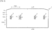
- FIG. 1 is a front view showing a metal wall material 1 according to an embodiment of the present invention
- FIG. 2 is a back view showing the metal wall material 1 in FIG. 1
- FIG. 3 is a cross-sectional view of the metal wall material 1 taken along the line III-III in FIG. 1
- FIG. 4 is an explanatory view showing another aspect of the body portion in FIG. 1
- FIG. 5 is explanatory view showing a wall construction structure and wall construction method using the metal wall material 1 in FIG 1 .
- a metal wall member 1 as shown in FIGS. 1 to 3 is arranged together with other metal wall members on a wall base of a building such as a house, as shown in FIG. 5 .
- the metal wall member 1 includes a front substrate 10, a back substrate 11, and a core material 12.
- the front substrate 10 is made of a metal sheet and appears on the outer surface of the wall as the metal wall material 1 is placed on the wall base.
- the metal sheet making up the front substrate 10 that can be used includes a hot-dip Zn plated steel sheet, a hot-dip Al plated steel sheet, a hot-dip Zn plated stainless steel sheet, a hot-dip Al plated stainless steel sheet, a stainless steel sheet, an Al sheet, a Ti sheet, a coated hot-dip Zn plated steel sheet, a coated hot-dip Al plated steel sheet, a coated hot-dip Zn plated stainless steel sheet, a coated hot-dip Al plated stainless steel sheet, a coated hot-dip Al plated stainless steel sheet, a coated stainless steel sheet, a coated Al sheet or a coated Ti sheet.
- the thickness of the metal sheet is 0.5 mm or less.
- An increasing thickness of the metal sheet will result in increased strength of the wall material, while resulting in increased weight of the wall material.
- the thickness of the metal sheet of 0.5 mm or less can prevent the weight of the metal wall material 1 from becoming excessive.
- the metal sheet has a thickness of 0.27 mm or more.
- the thickness of the metal sheet of 0.27 mm or more can ensure strength required for the wall, and sufficiently provide wind pressure resistance performance.
- the wind pressure resistance performance refers to performance for which the metal wall material 1 can withstand strong wind without buckling of the metal wall material 1.
- the front substrate 10 includes a box-shaped body portion 100 having a top plate portion 101 and peripheral wall portions 102.
- the body portion 100 is preferably formed by performing drawing or bulging processing on a metal sheet.
- each of the side wall portions 102 can have a wall surface that is continuous in the circumferential direction of the front substrate 10, and any likelihood that water enters the inside of the body portion 100 can be reduced.
- the steel sheet (the hot-dip Zn plated steel sheet, the hot-dip Al plated steel sheet, the hot-dip Zn plated stainless steel sheet, the hot-dip Al plated stainless steel sheet, the stainless steel sheet, the Al sheet, the Ti sheet, the coated hot-dip Zn plated steel sheet, the coated hot-dip Al plated steel sheet, the coated hot-dip Zn plated stainless steel sheet, the coated hot-dip Al plated stainless steel sheet or the coated stainless steel sheet) is used as the metal sheet of the front substrate 10 and when the body portion 100 is formed by the drawing or bulging processing, the hardness of the peripheral wall portions 102 are increased by work hardening.
- each peripheral wall portion 102 can be increased to about 1.4 to 1.6 times the hardness before the working.
- the wind pressure resistance performance of the metal wall member 1 is significantly improved by virtue of the fact that each peripheral wall portion 102 has the wall surface that is continuous in the circumferential direction of the front substrate 10, as described above, and by virtue of the fact that the hardness of each peripheral wall portion 102 is increased by work hardening.
- the back substrate 11 is a member that is arranged on the back side of the front substrate 10 so as to covert an opening of the body portion 100.
- the back substrate 11 that can be used include lightweight materials such as an aluminum foil, aluminum vapor deposited paper, aluminum hydroxide paper, calcium carbonate paper, resin films or glass fiber paper and the like. The use of these lightweight materials for the back substrate 11 allows prevention of an increase in the weight of the metal wall material 1.
- the core material 12 is made of, for example a foamed resin or the like, and is filled between the body portion 100 of the front substrate 10 and the back substrate 11.
- the filling of the core material 12 between the body portion 100 of the front substrate 10 and the back substrate 11 can lead to a stronger adhesion of the core material 12 to the inside of the body portion 100 as compared with an embodiment where a backing material such as a resin sheet or the like is attached onto the back side of the front substrate 11, so that the performance required for the wall materials, such as rainfall noise reduction, and heat insulation, can be improved.
- the material of the core material 12 includes, but not limited to, for example, urethane, phenol and cyanurate resins.
- certified noncombustible materials are suitably used.
- the test for certification of noncombustible material is conducted by a heat release test according to the cone calorimeter test method defined in ISO 5660-1. If the foamed resin for forming the core material 12 is urethane having a higher calorific value or the like, the thickness of the core material 12 may be decreased, or inorganic expandable particles may be incorporated into the foamed resin.
- a height h of the body portion 100 filled with the core material 12 is preferably 4 mm or more and 8 mm or less.
- the height h of the body portion 100 of 4 mm or more enables sufficiently higher strength of the body portion 100, and improved wind pressure resistance.
- the height h of 4 mm or more can also provide improved heat insulation properties.
- the height h of the body portion 100 of 8 mm or less can prevent the organic mass of the core material 12 from becoming excessive, and can allow certification of noncombustible material to be more reliably obtained.
- the metal wall material 1 is adapted such that a width direction 100a (a longitudinal direction) of the body portion 100 extends along a direction 4 parallel to an eave of the wall, and a depth direction 100b (a short direction) of the body portion 100 as described below extends along an upper-lower direction 5 of the wall.
- Each metal wall material 1 is fastened to the wall base by driving fastening members such as screws or nails.
- the metal wall material 1 on the lower side is arranged on the wall base while being overlapped onto the metal wall material 1 on the lower side.
- the top plate portion 101 of the body portion 100 includes a plurality of tightening indicators 2 spaced apart from each other along the width direction 100a of the body portion 100, and a protruding rib 3 arranged around each tightening indicator 2.
- the tightening indicators 2 and the protruding ribs 3 are described below in more detail.
- FIG. 6 is an enlarged plan view of the region VI in FIG. 1
- FIG. 7 is a cross-sectional view taken along the line VII-VII in FIG. 6
- FIG. 8 is a plan view showing a circle that falls within the inner region in FIG. 6 .
- the tightening indicators 2 indicate positions for driving the tightening members into the metal wall material 1. As shown in FIGS. 6 and 7 , each of the tightening indicators 2 of this embodiment is composed of a concave portion having a circular shape in plan view.
- each of the tightening indicators 2 may present any other form in which the operator can visually or tactually recognize the tightening position of the tightening member, such as, for example, a convex body, an opening, or a printed or engraved symbol.
- Each protruding rib 3 is formed by a plurality of protrusions 30 disposed along a side of a rectangle extending in the depth direction 100b of the body portion 100.
- Each tightening indicator 2 is disposed in an inner region 3a of each protruding rib 3. That is, the metal wall material 1 according to the present embodiment is configured such that the tightening member is driven into the inner region 3a of the protruding rib 3, and the tightening member is driven into the inner region 3a of the protruding rib 3 when carrying out wall construction (creating a wall) as shown in FIG. 5 .
- each protrusion 30 is structured by allowing a part of the metal sheet forming the top plate portion 101 to protrude.
- a vertical inner wall 30a of each protrusion 30 extends in a direction intersecting with a wall surface of the inner region 3a of the protruding rib 3, and can be resistant to deformation of the inner region 3a when the tightening member is tightened to the inner region 3a (the tightening indicator 2) of the protruding rib 3. That is, the tightening member is driven into the inner region 3a (the tightening indicator 2) of the protruding rib 3, thereby reducing a depression or buckling of the front substrate 10 due to the driving of the tightening member.
- each protruding rib 3 is provided with a plurality of opening portions 31 that communicate an outer region 3b with the inner region 3a of the protruding rib 3.
- the four opening portions 31 are formed by lacking the protrusions 30 at both ends of the upper and lower sides of the rectangle.
- surfaces under the same conditions as those of the surfaces of the inner region 3a and the outer region 3b of the protruding rib 3 preferably extend.
- the opening portions 31 positioned at both ends of the lower side of the rectangle form lower side opening portions 31E positioned on the lower sides of the protruding rib 3 when the metal wall material 1 is disposed on the wall base.
- the lower side means a downstream side in a flow direction of the wall.
- a ratio of the opening portions 31 in each protruding rib 3 (hereinafter referred to as an opening ratio) is preferably 50% or less.
- the center angles corresponding to the opening portions are angles ⁇ 1 to ⁇ n between straight lines corresponding to the respective opening portions 31a when a circle having the largest radius that falls within the inner region 3a is drawn as shown in FIG. 8 , and the straight lines passing through the center of the circle and both inner ends of each opening portion 31a are drawn.
- the opening ratio (%) ⁇ ( ⁇ 1 + ⁇ 2 + ⁇ 3 + ⁇ 4) / 360 ⁇ ⁇ 100.
- the circle that falls within the inner region 3a means a circle that is located inside the protruding rib 3 and that does not extend beyond the vertical inner wall 30a of all the protruding portions 30.
- the symbol n is an arbitrary positive number corresponding to the number of opening portions 31.
- the opening ratio of the protruding rib 3 of 50% or less can suppress deformation of the front substrate 10 due to the driving of the tightening member to a smaller level.
- Each protrusion 30 preferably has a height H of 0.2 mm or more.
- the height H corresponds to a distance between a surface of the inner region 3a or the outer region 3b of the protruding rib 3 and a top of the protruding portion 30.
- the height of each protrusion 30 of 0.2 mm or more can suppress the deformation of the front substrate 10 due to the driving of the tightening member to a smaller level.
- a value (W/H) obtained by dividing a width W of each protrusion 30 by the height H of each protrusion 30 is preferably 3 or more.
- the width W corresponds to a distance between the vertical inner wall 30a and a vertical outer wall of the protrusion 30.
- the value of W/H of 3 or more can avoid the processing of forming the protrusions 30 from being severe, and more reliably avoid cracks from occurring in a coated film formed on the surface of the metal sheet forming the top plate portion 101.
- a shortest distance L from the center position of the inner region 3a to each protrusion 30 is 5 mm or more and 20 mm or less.
- the shortest distance L from the center position of the inner region 3a to each protrusion 30 can be defined by a radius of a circle having the largest radius that falls within the inner region 3a (see FIG. 8 ).
- the shortest distance L of 5 mm or more and 20 mm or less can suppress the deformation of the front substrate 10 due to the driving of the tightening member to a smaller level.
- FIG. 9 is explanatory view showing a variation of the protruding rib 3 in FIG. 6 .
- the protrusion(s) 30 forming each protruding rib 3 may be arranged along a circle.
- the protruding rib 3 may be structured by one protruding portion 30, and as shown in FIGS. 9(b) to (d) and (h) , the protruding rib 3 may be structured by a plurality of protruding portions 30.
- a plurality of opening portions 31 may be arranged to face each other with the center positions of the protruding rib 3 interposed therebetween, or as shown in FIG. 9(e) and (f) , one opening portion 31 may be provided such that the opening rate of the protruding rib 3 is 50%. As shown in FIG. 9(h) , a part of the opening portions 31 may be the lower side opening portion 31E while the opening ratio of the protruding rib 3 is 50%.
- FIG. 10 is explanatory view showing a further variation of the protruding rib 3 in FIG. 6 .
- the protrusion(s) 30 forming each protruding rib 3 may be disposed along a side of a square.
- the protruding rib 3 may be structured by one protrusion 30.
- the protruding rib 3 may be structured by a plurality of protrusions 30.
- a plurality of opening portions 31 may be arranged to face each other with the center positions of the protruding rib 3 interposed therebetween, or as shown in FIG. 10(e) , one opening portion 31 may be provided such that the opening ratio of the protruding rib 3 is 50%. As shown in FIG. 10(h) , a part of the opening portions 31 may be the lower opening portion 31E while the opening ratio of the protruding rib 3 is 50%.
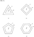
- FIG. 11 is explanatory view showing other variation of the protruding rib 3 in FIG. 6 .
- the protruding portion 30 forming the protruding rib 3 may be disposed along sides of a triangle, a rhombus (quadrangle), a pentagon and an octagon. Further, the protrusion 30 may be arrange along sides of a polygon having twist angles. Even if the protrusions 30 are arranged along the sides of the triangle, rhombus (quadrangle), pentagon and octagon as shown in FIGS. 11(a) to (e) , the opening portion(s) can be provided as shown in FIGS. 9 and 10 .
- Glass fiber paper having a size of 0.2 mm, Al metallized paper having a size of 0.2 mm, a PE resin film having a size of 0.2 mm, an Al foil having a size of 0.1 mm or a coated hot-dip Zn plated steel sheet having a size of 0.27 mm was used as the back substrate 11.
- a two-liquid mixture type foam resin was used as the core material 12.
- the mixing ratio of a polyol component and isocyanate, phenol or cyanurate component was 1:1, in a ratio by weight.
- the front substrate 10 was processed to have a predetermined thickness and shape of the wall material.
- the back substrate 11 was then disposed on the back side of the front substrate 10 so as to cover the opening of the body portion 100, and the foam resin was injected into the gap between the body portion 100 of the front substrate 10 and the back substrate 11, using a commercially available high-pressure injection machine. Foaming of the resin was accomplished by maintaining the resin for 2 minutes in a mold at which the temperature was adjusted to 70°C by circulating hot water; subsequently, the wall material was removed from the mold, and was allowed to stand for 5 minutes at room temperature of 20°C, to complete foaming of the resin.
- the metal sheet extending from a lower edge of the body portion 100 toward the outer direction of the body portion 100 was cut such that a protruding width of a flange was 5 mm, and the cut metal sheet was subjected to a bending process by means of a bender to have a predetermined shape.
- the dimensions of the final metal wall member 1 were 414 mm ⁇ 910 mm.
- the thickness of the final wall material was in the range of from 3 mm to 8 mm.
- the unit weight of each wall material was measured and evaluated from construction properties in accordance with the following criteria.
- a commercially available best screw (a diameter of 4.0 mm ⁇ ⁇ a length of 35 mm) from YAMAKI SANGYO co., ltd., and an impact driver (TD136D from Makita Corporation) were used to tighten two wall material sheets stacked to each other.
- an impact driver (TD136D from Makita Corporation) were used to tighten two wall material sheets stacked to each other.
- the depression of the tightened wall material on the upper side were measured by means of a gap gauge and evaluated according to the following evaluation criteria:
- the wall material was inclined at a gradient of 15°, 1000 mL of tap water was allowed to flow over the wall material, and a situation where the water remained in the inner region 3a of the protruding rib 3 was visually evaluated according to the following evaluation criteria:
- the unit weight of the wall material was 250 N/m 2 or more, and the weight of the wall material was evaluated as ⁇ .
- the unit weight of the wall material was able to be less than 20 N/sheet by the thickness of the metal sheet forming the front substrate 10 being 0.5 mm or less.
- the shortest distance L from the center position of the inner region 3a to the protrusion 30 was more than 20 mm, the depression during tightening was 2 mm or more, and the depression during tightening was evaluated as ⁇ .
- the shortest distance L is preferably 20 mm or less.
- the protrusion 30 may become a barrier and hinder the fastening work when the wall material is fastened by a nail or a screw using a hammer, a driver, or an electric tool.
- the shortest distance L is preferably 5 mm or more.
- the depression during tightening was 2 mm or more, and the depression during tightening was evaluated as ⁇ .
- the depression during tightening could be less than 2 mm.
- the top plate portion 101 of the body portion 100 comprises at least one protruding rib 3 composed of at least one protruding portion 30 disposed along the side of the polygon or along the circle, and the tightening member is driven into the inner region 3a of the protruding rib 3, so that the depression or buckling of the front substrate 10 due to the driving of the tightening member can be reduced.
- the protruding rib 3 is provided with at least one opening portion 31 for communicating the outer region 3b with the inner region 3a of the protruding rib 3, so that the flow of air passing inside and outside the protruding rib 3 can be ensured even if the upper portion of the projected rib 3 is blocked by the other metal wall material.
- moisture such as rainwater enters the inner region 3a of the protruding rib 3
- evaporation of the water can be promoted, thereby reducing a risk where moisture remains in the inner region 3a of the protruding rib 3.
- At least one opening portion 31 includes an lower side opening portion 31E located on the lower side of the protruding rib 3 when the metal wall material 1 is disposed on the wall base, so that moisture that has entered the inner region 3a can escape through the lower side opening portion 31E to the outer region 3b of the protruding rib 3, thereby reducing a risk where the moisture will remain in the inner region 3a of the protruding rib 3.
- the ratio (opening ratio) of the opening portions 31 in the protruding rib 3 is 50% or less, so that deformation of the front substrate 10 due to the driving of the tightening member can be suppressed to a smaller level.
- the height H of the protrusion 30 is 0.2 mm or more, so that deformation of the front substrate 10 due to the driving of the tightening member can be suppressed to a smaller level.
- the value (W/H) obtained by dividing the width W of the protrusion 30 by the height H of the protrusion 30 is 3 or more, so that cracking can be more reliably prevented from occurring on the coated film formed on the surface of the metal sheet forming the top plate portion 101.
- the shortest distance from the center position of the inner region 3a to the protrusion 30 is 5 mm or more and 20 mm or less, so that deformation of the front substrate 10 due to the driving of the tightening member can be suppressed to a smaller level.
- the sheet thickness of the metal sheet forming the front substrate 10 is 0.5 mm or less, so that excessively increased weight of the metal wall material 1 can be more reliably avoided.
Landscapes
- Engineering & Computer Science (AREA)
- Architecture (AREA)
- Civil Engineering (AREA)
- Structural Engineering (AREA)
- Finishing Walls (AREA)
Abstract
Description
- The present invention relates to a metal wall material that is tightened on a wall base by driving a tightening member, and a wall construction method using the same.
- The present inventors have attempted implementation of a surface member for overlap roofing as disclosed in the following Patent Document 1, i.e., a metal wall material including a metal front substrate; a back substrate disposed on a back side of the front substrate; and a core material made of a foamed resin filled between the front substrate and the back substrate. After being disposed on a wall base, such a metal wall material is tightened to the wall base by driving a tightening member such as a nail or a screw.
- Japanese Patent Application Publication No.
S64-37826 A - When the tightening member is driven into the metal wall material as described above, a pressure caused by the driving of the binding member may lead to a depression or buckling around the driven position of the tightening member. Such a depression or buckling will cause retention of moisture such as rain water that will cause corrosion of the metal wall material, and deterioration of the design of the metal wall material. In order to prevent the depression or buckling, a method of increasing a sheet thickness of the front substrate can be considered. However, such a method results in an increase in the weight of the wall.
- The present invention has been made to solve the above problems. An object of the present invention is to provide a metal wall material that can decrease a depression and buckling in the front substrate due to the driving of the tightening member, and a wall construction method using the same.
- The present invention relates to a metal wall material comprising: a front substrate made of a metal sheet, the front substrate comprising a body portion formed into a box shape; a back substrate arranged on a back side of the front substrate so as to cover an opening of the body portion; and a core material filled between the body portion and the back substrate, the metal wall material being tightened to a wall base by driving at least one tightening member into the body portion, wherein a top plate portion of the body portion comprises at least one protruding rib comprised of at least one protrusion disposed along a side of a polygon or along a circle, and wherein the metal wall material is configured such that the tightening member is driven into an inner region of the protruding rib.
- The present invention also relates to a wall construction method using a metal wall material comprising: a front substrate made of a metal sheet, the front substrate comprising a body portion formed into a box shape; a back substrate arranged on a back side of the front substrate so as to cover an opening of the body portion; and a core material filled between the body portion and the back substrate, a top plate portion of the body portion comprising at least one protruding rib comprised of at least one protrusion disposed along a side of a polygon or along a circle, wherein the wall construction method comprises the steps of: placing the metal wall material on a wall base; and driving at least one tightening member into an inner region of the protruding rib to tighten the metal wall material to the wall base.
- According to the metal wall material and the wall construction method using the same according to the present invention, the protruding rib comprised of at least one protrusion disposed along a side of a polygon or along a circle is provided on the top plate portion of the body portion and the tightening member is driven into the inner region of the protruding rib, thereby enabling the depression or buckling in the front substrate due to the driving of the tightening members to be reduced.
-
-
FIG. 1 is a front view showing a metal wall material according to an embodiment of the present invention. -
FIG. 2 is a back view showing the metal wall material 1 inFIG. 1 . -
FIG. 3 is a cross-sectional view of the metal wall material taken along the line III-III in -
FIG. 1 . -
FIG. 4 is an explanatory view showing another aspect of the body portion inFIG. 1 . -
FIG. 5 is explanatory view showing a wall construction structure and wall construction method using the metal wall material 1 inFIG 1 . -
FIG. 6 is an enlarged plan view of the region VI inFIG. 1 . -
FIG. 7 is a cross-sectional view taken along the line VII-VII inFIG. 6 . -
FIG. 8 is a plan view showing a circle that falls within the inner region inFIG. 6 . -
FIG. 9 is explanatory view showing a variation of the protruding rib inFIG. 6 . -
FIG. 10 is explanatory view showing a further variation of the protruding rib inFIG. 6 . -
FIG. 11 is an explanatory view showing a still another variation of the protruding rib inFIG. 6 . - Embodiments for carrying out the present invention will be described with reference to the drawings.
-
FIG. 1 is a front view showing a metal wall material 1 according to an embodiment of the present invention,FIG. 2 is a back view showing the metal wall material 1 inFIG. 1 ,FIG. 3 is a cross-sectional view of the metal wall material 1 taken along the line III-III inFIG. 1 ,FIG. 4 is an explanatory view showing another aspect of the body portion inFIG. 1 , andFIG. 5 is explanatory view showing a wall construction structure and wall construction method using the metal wall material 1 inFIG 1 . - A metal wall member 1 as shown in
FIGS. 1 to 3 is arranged together with other metal wall members on a wall base of a building such as a house, as shown inFIG. 5 . As particularly shown inFIG. 3 , the metal wall member 1 includes afront substrate 10, aback substrate 11, and acore material 12. - The
front substrate 10 is made of a metal sheet and appears on the outer surface of the wall as the metal wall material 1 is placed on the wall base. The metal sheet making up thefront substrate 10 that can be used includes a hot-dip Zn plated steel sheet, a hot-dip Al plated steel sheet, a hot-dip Zn plated stainless steel sheet, a hot-dip Al plated stainless steel sheet, a stainless steel sheet, an Al sheet, a Ti sheet, a coated hot-dip Zn plated steel sheet, a coated hot-dip Al plated steel sheet, a coated hot-dip Zn plated stainless steel sheet, a coated hot-dip Al plated stainless steel sheet, a coated stainless steel sheet, a coated Al sheet or a coated Ti sheet. - Preferably, the thickness of the metal sheet is 0.5 mm or less. An increasing thickness of the metal sheet will result in increased strength of the wall material, while resulting in increased weight of the wall material. The thickness of the metal sheet of 0.5 mm or less can prevent the weight of the metal wall material 1 from becoming excessive. In addition, the metal sheet has a thickness of 0.27 mm or more. The thickness of the metal sheet of 0.27 mm or more can ensure strength required for the wall, and sufficiently provide wind pressure resistance performance. The wind pressure resistance performance refers to performance for which the metal wall material 1 can withstand strong wind without buckling of the metal wall material 1.
- The
front substrate 10 includes a box-shaped body portion 100 having atop plate portion 101 andperipheral wall portions 102. Thebody portion 100 is preferably formed by performing drawing or bulging processing on a metal sheet. By forming the box-shaped body portion 100 by performing the drawing or bulging processing, each of theside wall portions 102 can have a wall surface that is continuous in the circumferential direction of thefront substrate 10, and any likelihood that water enters the inside of thebody portion 100 can be reduced. However, it is also possible to bend the metal sheet having a shape as shown inFIG. 4 along the dashed lines in the figure to form the box-shaped body portion 100. - When the steel sheet (the hot-dip Zn plated steel sheet, the hot-dip Al plated steel sheet, the hot-dip Zn plated stainless steel sheet, the hot-dip Al plated stainless steel sheet, the stainless steel sheet, the Al sheet, the Ti sheet, the coated hot-dip Zn plated steel sheet, the coated hot-dip Al plated steel sheet, the coated hot-dip Zn plated stainless steel sheet, the coated hot-dip Al plated stainless steel sheet or the coated stainless steel sheet) is used as the metal sheet of the
front substrate 10 and when thebody portion 100 is formed by the drawing or bulging processing, the hardness of theperipheral wall portions 102 are increased by work hardening. More particularly, the Vickers hardness of eachperipheral wall portion 102 can be increased to about 1.4 to 1.6 times the hardness before the working. The wind pressure resistance performance of the metal wall member 1 is significantly improved by virtue of the fact that eachperipheral wall portion 102 has the wall surface that is continuous in the circumferential direction of thefront substrate 10, as described above, and by virtue of the fact that the hardness of eachperipheral wall portion 102 is increased by work hardening. - The
back substrate 11 is a member that is arranged on the back side of thefront substrate 10 so as to covert an opening of thebody portion 100. Theback substrate 11 that can be used include lightweight materials such as an aluminum foil, aluminum vapor deposited paper, aluminum hydroxide paper, calcium carbonate paper, resin films or glass fiber paper and the like. The use of these lightweight materials for theback substrate 11 allows prevention of an increase in the weight of the metal wall material 1. - The
core material 12 is made of, for example a foamed resin or the like, and is filled between thebody portion 100 of thefront substrate 10 and theback substrate 11. The filling of thecore material 12 between thebody portion 100 of thefront substrate 10 and theback substrate 11 can lead to a stronger adhesion of thecore material 12 to the inside of thebody portion 100 as compared with an embodiment where a backing material such as a resin sheet or the like is attached onto the back side of thefront substrate 11, so that the performance required for the wall materials, such as rainfall noise reduction, and heat insulation, can be improved. - The material of the
core material 12 includes, but not limited to, for example, urethane, phenol and cyanurate resins. For wall materials, however, certified noncombustible materials are suitably used. The test for certification of noncombustible material is conducted by a heat release test according to the cone calorimeter test method defined in ISO 5660-1. If the foamed resin for forming thecore material 12 is urethane having a higher calorific value or the like, the thickness of thecore material 12 may be decreased, or inorganic expandable particles may be incorporated into the foamed resin. - A height h of the
body portion 100 filled with thecore material 12 is preferably 4 mm or more and 8 mm or less. The height h of thebody portion 100 of 4 mm or more enables sufficiently higher strength of thebody portion 100, and improved wind pressure resistance. The height h of 4 mm or more can also provide improved heat insulation properties. The height h of thebody portion 100 of 8 mm or less can prevent the organic mass of thecore material 12 from becoming excessive, and can allow certification of noncombustible material to be more reliably obtained. - As shown in
FIG. 5 , the metal wall material 1 is adapted such that awidth direction 100a (a longitudinal direction) of thebody portion 100 extends along adirection 4 parallel to an eave of the wall, and adepth direction 100b (a short direction) of thebody portion 100 as described below extends along an upper-lower direction 5 of the wall. Each metal wall material 1 is fastened to the wall base by driving fastening members such as screws or nails. Further, in the upper-lower direction 5, the metal wall material 1 on the lower side is arranged on the wall base while being overlapped onto the metal wall material 1 on the lower side. - Returning to
FIG. 1 , thetop plate portion 101 of thebody portion 100 includes a plurality of tighteningindicators 2 spaced apart from each other along thewidth direction 100a of thebody portion 100, and aprotruding rib 3 arranged around each tighteningindicator 2. The tighteningindicators 2 and theprotruding ribs 3 are described below in more detail. -
FIG. 6 is an enlarged plan view of the region VI inFIG. 1 ,FIG. 7 is a cross-sectional view taken along the line VII-VII inFIG. 6 , andFIG. 8 is a plan view showing a circle that falls within the inner region inFIG. 6 . The tighteningindicators 2 indicate positions for driving the tightening members into the metal wall material 1. As shown inFIGS. 6 and7 , each of the tighteningindicators 2 of this embodiment is composed of a concave portion having a circular shape in plan view. However, each of the tighteningindicators 2 may present any other form in which the operator can visually or tactually recognize the tightening position of the tightening member, such as, for example, a convex body, an opening, or a printed or engraved symbol. - Each protruding
rib 3 is formed by a plurality ofprotrusions 30 disposed along a side of a rectangle extending in thedepth direction 100b of thebody portion 100. Each tighteningindicator 2 is disposed in aninner region 3a of eachprotruding rib 3. That is, the metal wall material 1 according to the present embodiment is configured such that the tightening member is driven into theinner region 3a of theprotruding rib 3, and the tightening member is driven into theinner region 3a of theprotruding rib 3 when carrying out wall construction (creating a wall) as shown inFIG. 5 . - As shown in
FIG. 7 , eachprotrusion 30 is structured by allowing a part of the metal sheet forming thetop plate portion 101 to protrude. A verticalinner wall 30a of eachprotrusion 30 extends in a direction intersecting with a wall surface of theinner region 3a of theprotruding rib 3, and can be resistant to deformation of theinner region 3a when the tightening member is tightened to theinner region 3a (the tightening indicator 2) of theprotruding rib 3. That is, the tightening member is driven into theinner region 3a (the tightening indicator 2) of theprotruding rib 3, thereby reducing a depression or buckling of thefront substrate 10 due to the driving of the tightening member. - As shown in
FIG. 6 , each protrudingrib 3 is provided with a plurality of openingportions 31 that communicate anouter region 3b with theinner region 3a of theprotruding rib 3. For the protrudingrib 3 according to the present embodiment, the four openingportions 31 are formed by lacking theprotrusions 30 at both ends of the upper and lower sides of the rectangle. In theopening portion 31, surfaces under the same conditions as those of the surfaces of theinner region 3a and theouter region 3b of theprotruding rib 3 preferably extend. By providing the openingportion 31 in the protrudingrib 3, a flow of air passing inside and outside the protrudingrib 3 can be ensured even if an upper portion of theprotruding rib 3 is blocked by the other metal wall material as shown inFIG. 5 . This can allow evaporation of moisture such as rainwater to be facilitated even if the moisture enters theinner region 3a of theprotruding rib 3, thereby reducing any risk where moisture will remain in theinner region 3a of theprotruding rib 3. - Here, the opening
portions 31 positioned at both ends of the lower side of the rectangle form lowerside opening portions 31E positioned on the lower sides of theprotruding rib 3 when the metal wall material 1 is disposed on the wall base. The lower side means a downstream side in a flow direction of the wall. By providing such lowerside opening portions 31E, the moisture that has entered theinner region 3a of theprotruding rib 3 can escape through the lowerside opening portions 31E to theouter region 3b of theprotruding rib 3, thereby enabling a risk where the moisture will remain in theinner region 3a of theprotruding rib 3 to be reduced. - A ratio of the opening
portions 31 in each protruding rib 3 (hereinafter referred to as an opening ratio) is preferably 50% or less. The opening ratio can be defined by the following equation:
- The center angles corresponding to the opening portions are angles θ1 to θn between straight lines corresponding to the respective opening portions 31a when a circle having the largest radius that falls within the
inner region 3a is drawn as shown inFIG. 8 , and the straight lines passing through the center of the circle and both inner ends of each opening portion 31a are drawn. In the case of the embodiment where the four opening portions 31a are provided on the protrudingrib 3 as shown inFIG. 8 , it is expressed as the opening ratio (%) = {(θ1 + θ2 + θ3 + θ4) / 360} × 100. The circle that falls within theinner region 3a means a circle that is located inside the protrudingrib 3 and that does not extend beyond the verticalinner wall 30a of all the protrudingportions 30. Further, the symbol n is an arbitrary positive number corresponding to the number of openingportions 31. As will be described later with reference to Examples, the opening ratio of theprotruding rib 3 of 50% or less can suppress deformation of thefront substrate 10 due to the driving of the tightening member to a smaller level. - Each
protrusion 30 preferably has a height H of 0.2 mm or more. The height H corresponds to a distance between a surface of theinner region 3a or theouter region 3b of theprotruding rib 3 and a top of the protrudingportion 30. As will be described later with reference to Examples, the height of eachprotrusion 30 of 0.2 mm or more can suppress the deformation of thefront substrate 10 due to the driving of the tightening member to a smaller level. - A value (W/H) obtained by dividing a width W of each
protrusion 30 by the height H of eachprotrusion 30 is preferably 3 or more. The width W corresponds to a distance between the verticalinner wall 30a and a vertical outer wall of theprotrusion 30. As will be described later with reference to Examples, the value of W/H of 3 or more can avoid the processing of forming theprotrusions 30 from being severe, and more reliably avoid cracks from occurring in a coated film formed on the surface of the metal sheet forming thetop plate portion 101. - It is preferable that a shortest distance L from the center position of the
inner region 3a to eachprotrusion 30 is 5 mm or more and 20 mm or less. The shortest distance L from the center position of theinner region 3a to eachprotrusion 30 can be defined by a radius of a circle having the largest radius that falls within theinner region 3a (seeFIG. 8 ). As will be described later with reference to Examples, the shortest distance L of 5 mm or more and 20 mm or less can suppress the deformation of thefront substrate 10 due to the driving of the tightening member to a smaller level. - Next,
FIG. 9 is explanatory view showing a variation of theprotruding rib 3 inFIG. 6 . As shown inFIGS. 9(a) to 9(h) , the protrusion(s) 30 forming eachprotruding rib 3 may be arranged along a circle. As shown inFIGS. 9(a), (e), (f) and (g) , the protrudingrib 3 may be structured by one protrudingportion 30, and as shown inFIGS. 9(b) to (d) and (h) , the protrudingrib 3 may be structured by a plurality of protrudingportions 30. - As shown in
FIGS. 9(b) to 9(d) , a plurality of openingportions 31 may be arranged to face each other with the center positions of theprotruding rib 3 interposed therebetween, or as shown inFIG. 9(e) and (f) , oneopening portion 31 may be provided such that the opening rate of theprotruding rib 3 is 50%. As shown inFIG. 9(h) , a part of the openingportions 31 may be the lowerside opening portion 31E while the opening ratio of theprotruding rib 3 is 50%. - Next,
FIG. 10 is explanatory view showing a further variation of theprotruding rib 3 inFIG. 6 . As shown inFIGS. 10(a) to 10(h) , the protrusion(s) 30 forming eachprotruding rib 3 may be disposed along a side of a square. As shown inFIGS. 10(a) and 10(e) , the protrudingrib 3 may be structured by oneprotrusion 30. As shown inFIGS. 10(b) to 10(d) and FIGS. 10(f) to (h) , the protrudingrib 3 may be structured by a plurality ofprotrusions 30. - As shown in
FIGS. 10(b) to (d), (f) and (g) , a plurality of openingportions 31 may be arranged to face each other with the center positions of theprotruding rib 3 interposed therebetween, or as shown inFIG. 10(e) , oneopening portion 31 may be provided such that the opening ratio of theprotruding rib 3 is 50%. As shown inFIG. 10(h) , a part of the openingportions 31 may be thelower opening portion 31E while the opening ratio of theprotruding rib 3 is 50%. - Next,
FIG. 11 is explanatory view showing other variation of theprotruding rib 3 inFIG. 6 . As shown inFIGS. 11(a) to 11(e) , the protrudingportion 30 forming theprotruding rib 3 may be disposed along sides of a triangle, a rhombus (quadrangle), a pentagon and an octagon. Further, theprotrusion 30 may be arrange along sides of a polygon having twist angles. Even if theprotrusions 30 are arranged along the sides of the triangle, rhombus (quadrangle), pentagon and octagon as shown inFIGS. 11(a) to (e) , the opening portion(s) can be provided as shown inFIGS. 9 and10 . - Examples are now illustrated. The inventors experimentally produced samples of the metal wall material 1 under conditions given below.
- A coated hot-dip Zn-55% Al plated steel sheet, a coated hot-dip Zn-6% AI-3% Mg plated steel sheet or a coated hot-dip Al plated steel sheet, which had a size of 0.20 mm to 0.6 mm, was used as the material of the
front substrate 10.
Glass fiber paper having a size of 0.2 mm, Al metallized paper having a size of 0.2 mm, a PE resin film having a size of 0.2 mm, an Al foil having a size of 0.1 mm or a coated hot-dip Zn plated steel sheet having a size of 0.27 mm was used as theback substrate 11.
A two-liquid mixture type foam resin was used as thecore material 12. The mixing ratio of a polyol component and isocyanate, phenol or cyanurate component was 1:1, in a ratio by weight. - The
front substrate 10 was processed to have a predetermined thickness and shape of the wall material. Theback substrate 11 was then disposed on the back side of thefront substrate 10 so as to cover the opening of thebody portion 100, and the foam resin was injected into the gap between thebody portion 100 of thefront substrate 10 and theback substrate 11, using a commercially available high-pressure injection machine. Foaming of the resin was accomplished by maintaining the resin for 2 minutes in a mold at which the temperature was adjusted to 70°C by circulating hot water; subsequently, the wall material was removed from the mold, and was allowed to stand for 5 minutes at room temperature of 20°C, to complete foaming of the resin. - After complete of the foaming of the resin, the metal sheet extending from a lower edge of the
body portion 100 toward the outer direction of thebody portion 100 was cut such that a protruding width of a flange was 5 mm, and the cut metal sheet was subjected to a bending process by means of a bender to have a predetermined shape. The dimensions of the final metal wall member 1 were 414 mm × 910 mm. The thickness of the final wall material was in the range of from 3 mm to 8 mm. - Such samples were subjected to the following evaluations: (1) evaluation of the weight of the wall material; (2) evaluation of a depression during tightening; (3) evaluation of cracking on the coated film; and (4) evaluation of ease of rainwater flow, while changing the shape of each
protruding rib 3, the presence or absence of the lowerside opening portion 31E, the height H of the protrudingportion 30, the shortest distance L from the center position of theinner region 3a to the protrudingportion 30, the value obtained by dividing the width W of theprotrusion 30 by the height H of theprotrusion 30, and the opening ratio (a ratio of the openingportions 31 in the protruding rib 3). The results are shown in the Table as shown below. -
Table 1: Details of Samples and Performance Evaluation Results Classification Details of Samples Performance Evaluation Results Thickness (mm) Rib Shape Presence or Absence of Eave Lower Side Opening Protrusion Height H (mm) Shortest Distance L (mm) 
Opening Ratio (%) Wall Material Weight Depression during Tightening Cracking on Coated Film Ease of Rainwater Flow Examples 1 0.3 Circular Present 0.3 10 17 10 ○ ○ ○ ○ 2 0.3 Rectangular Present 0.3 10 17 12.5 ○ ○ ○ ○ 3 0.3 Triangular Present 0.8 15 19 20 ○ ○ ○ ○ 4 0.35 Pentagonal Present 1 20 10 40 ○ ○ ○ ○ 5 0.35 Hexagonal Present 1 20 10 40 ○ ○ ○ ○ 6 0.5 Hexagonal Present 1 20 3 40 ○ ○ ○ ○ 7 0.4 Circular Present 0.5 10 10 15 ○ ○ ○ ○ Comparative Examples 1 0.6 Triangular Present 0.5 10 10 30 Δ ○ ○ ○ 2 0.3 Square Absent 0.3 10 10 52 ○ Δ ○ Δ 3 0.3 Square Present 0.3 23 15 15 ○ Δ ○ ○ 4 0.4 Pentagonal Present 0.1 10 10 15 ○ Δ ○ ○ 5 0.4 Hexagonal Present 0.3 10 2 15 ○ ○ Δ ○ 6 0.4 Circular Present 1.1 10 2.7 15 ○ ○ Δ ○ 7 0.27 Circular Absent 0.2 5 15 0 ○ ○ ○ Δ 8 0.3 Square Absent 0.3 5 10 0 ○ ○ ○ Δ - The unit weight of each wall material was measured and evaluated from construction properties in accordance with the following criteria.
- ○: unit weight of wall material of less than 20 N/sheet; and
- Δ: unit weight of wall material of 20 N/sheet or more.
- As the tightening member, a commercially available best screw (a diameter of 4.0 mmϕ × a length of 35 mm) from YAMAKI SANGYO co., ltd., and an impact driver (TD136D from Makita Corporation) were used to tighten two wall material sheets stacked to each other. For the depression during the tightening, the depression of the tightened wall material on the upper side were measured by means of a gap gauge and evaluated according to the following evaluation criteria:
- ○: Depression of less than 2mm during tightening; and
- Δ: Depression of 2mm or more during tightening.
- The cracking on the coated film which occurred on a coated steel sheet when forming the
protrusion 30 was visually observed with a magnifying glass at magnitudes of 10 times, and evaluated according to the following evaluation criteria: - ○: No cracking on the coated film was observed or minor cracking was observed; and
- Δ: Significant cracking on the coated film was observed.
- The wall material was inclined at a gradient of 15°, 1000 mL of tap water was allowed to flow over the wall material, and a situation where the water remained in the
inner region 3a of theprotruding rib 3 was visually evaluated according to the following evaluation criteria: - ○: Water fluently flowed and almost no water remained in the inner region;
- Δ: Water remained.
- As shown in Comparative Example 1, when the thickness of the metal sheet forming the
front substrate 10 was 0.6 mm, the unit weight of the wall material was 250 N/m2 or more, and the weight of the wall material was evaluated as Δ. On the other hand, as shown in the Examples, the unit weight of the wall material was able to be less than 20 N/sheet by the thickness of the metal sheet forming thefront substrate 10 being 0.5 mm or less. These results indicated that the thickness of the metal sheet forming thefront substrate 10 is preferably 0.5 mm or less. - As shown in Comparative Example 2, when the opening ratio of the
protruding rib 3 was more than 50%, the depression during tightening was 2 mm or more, and the depression during tightening was evaluated as Δ. On the other hand, as shown in Examples, when the opening ratio was 50% or less, the depression during tightening could be less than 2 mm. These results indicated that the opening ratio is preferably 50% or less. - As shown in Comparative Example 3, when the shortest distance L from the center position of the
inner region 3a to theprotrusion 30 was more than 20 mm, the depression during tightening was 2 mm or more, and the depression during tightening was evaluated as Δ. On the other hand, as shown in Examples, when the shortest distance L was 20 mm or less, the depression during tightening could be less than 2 mm. These result indicated that the shortest distance L is preferably 20 mm or less. In addition, when the shortest distance L is decreased, theprotrusion 30 may become a barrier and hinder the fastening work when the wall material is fastened by a nail or a screw using a hammer, a driver, or an electric tool. For this reason, the shortest distance L is preferably 5 mm or more. - As shown in Comparative Example 4, when the height H of the
protrusion 30 was less than 0.2 mm, the depression during tightening was 2 mm or more, and the depression during tightening was evaluated as Δ. On the other hand, as shown in Examples, when the height H of theprotrusion 30 was 0.2 mm or more, the depression during tightening could be less than 2 mm. These result indicated that the height H of theprotrusion 30 is preferably 0.2 mm or more. - As shown in Comparative Examples 5 and 6, when the value obtained by dividing the width W of the
protrusion 30 by the height H of theprotrusion 30 was less than 3, cracking occurred on the coated film, and the cracking on the coated film was evaluated as Δ. On the other hand, as shown in Examples, when the value obtained by dividing the width W of theprotrusion 30 by the height H of theprotrusion 30 was 3 or more, the cracking on the coated film could be avoided. These results indicated that the value obtained by dividing the width W of theprotrusion 30 by the height H of theprotrusion 30 is preferably 3 or more. - As shown in Comparative Examples 2, 7, and 8, when the lower
side opening portion 31E was not provided, water remained in theinner region 3a of theprotruding rib 3, and the ease of rainwater flow was evaluated as Δ. On the other hand, as shown in the Examples, when the lower side opening portion(s) 31E was/were provided, water remaining in theinner region 3a of theprotruding rib 3 could be avoided. These results indicated that it is preferable to provide the lower side opening portion(s) 31E. - In the metal wall material 1 and the wall construction method using the metal wall material 1, the
top plate portion 101 of thebody portion 100 comprises at least one protrudingrib 3 composed of at least one protrudingportion 30 disposed along the side of the polygon or along the circle, and the tightening member is driven into theinner region 3a of theprotruding rib 3, so that the depression or buckling of thefront substrate 10 due to the driving of the tightening member can be reduced. - Further, the protruding
rib 3 is provided with at least oneopening portion 31 for communicating theouter region 3b with theinner region 3a of theprotruding rib 3, so that the flow of air passing inside and outside the protrudingrib 3 can be ensured even if the upper portion of the projectedrib 3 is blocked by the other metal wall material. Thus, even if moisture such as rainwater enters theinner region 3a of theprotruding rib 3, evaporation of the water can be promoted, thereby reducing a risk where moisture remains in theinner region 3a of theprotruding rib 3. - Furthermore, at least one
opening portion 31 includes an lowerside opening portion 31E located on the lower side of theprotruding rib 3 when the metal wall material 1 is disposed on the wall base, so that moisture that has entered theinner region 3a can escape through the lowerside opening portion 31E to theouter region 3b of theprotruding rib 3, thereby reducing a risk where the moisture will remain in theinner region 3a of theprotruding rib 3. - Moreover, the ratio (opening ratio) of the opening
portions 31 in the protrudingrib 3 is 50% or less, so that deformation of thefront substrate 10 due to the driving of the tightening member can be suppressed to a smaller level. - Also, the height H of the
protrusion 30 is 0.2 mm or more, so that deformation of thefront substrate 10 due to the driving of the tightening member can be suppressed to a smaller level. - Further, the value (W/H) obtained by dividing the width W of the
protrusion 30 by the height H of theprotrusion 30 is 3 or more, so that cracking can be more reliably prevented from occurring on the coated film formed on the surface of the metal sheet forming thetop plate portion 101. - Furthermore, the shortest distance from the center position of the
inner region 3a to theprotrusion 30 is 5 mm or more and 20 mm or less, so that deformation of thefront substrate 10 due to the driving of the tightening member can be suppressed to a smaller level. - Moreover, the sheet thickness of the metal sheet forming the
front substrate 10 is 0.5 mm or less, so that excessively increased weight of the metal wall material 1 can be more reliably avoided.
Claims (9)
- A metal wall material comprising: a front substrate made of a metal sheet, the front substrate comprising a body portion formed into a box shape; a back substrate arranged on a back side of the front substrate so as to cover an opening of the body portion; and a core material filled between the body portion and the back substrate, the metal wall material being tightened to a wall base by driving at least one tightening member into the body portion,
wherein a top plate portion of the body portion comprises a protruding rib comprised of at least one protrusion disposed along a side of a polygon or along a circle, and wherein the metal wall material is configured such that the tightening member is driven into an inner region of the protruding rib. - The metal wall material according to claim 1, wherein the protruding rib comprises at least one opening portion that communicates an outer region with the inner region of the protruding rib.
- The metal wall material according to claim 2, wherein the at least one opening portion includes a lower side opening portion located on a lower side of the protruding rib when the metal wall material is disposed on the wall base.
- The metal wall material according to claim 2 or 3, wherein a ratio of the opening portions in the protruding rib is 50% or less.
- The metal wall material according to any one of claims 1 to 4, wherein the protrusion has a height of 0.2 mm or more.
- The metal wall material according to claim 5, wherein a value obtained by dividing a width of the protrusion by the height of the protrusion is 3 or more.
- The metal wall material according to any one of claims 1 to 6, wherein a shortest distance from a center position of the inner region to the protrusion is 5 mm or more and 20 mm or less.
- The metal wall material according to any one of claims 1 to 7, wherein the metal sheet forming the front substrate has a thickness of 0.5 mm or less.
- A wall construction method using a metal wall material comprising: a front substrate made of a metal sheet, the front substrate comprising a body portion formed into a box shape; a back substrate arranged on a back side of the front substrate so as to cover an opening of the body portion; and a core material filled between the body portion and the back substrate, a top plate portion of the body portion comprising a protruding rib comprised of at least one protrusion disposed along a side of a polygon or along a circle, the wall construction method comprising the steps of:placing the metal wall material on a wall base; anddriving at least one tightening member into an inner region of the protruding rib to tighten the metal wall material to the wall base.
Applications Claiming Priority (2)
| Application Number | Priority Date | Filing Date | Title |
|---|---|---|---|
| JP2017188623A JP6981147B2 (en) | 2017-09-28 | 2017-09-28 | Metal wall material and wall construction method using it |
| PCT/JP2018/035136 WO2019065524A1 (en) | 2017-09-28 | 2018-09-21 | Metal wall material and wall construction method using same |
Publications (2)
| Publication Number | Publication Date |
|---|---|
| EP3690164A1 true EP3690164A1 (en) | 2020-08-05 |
| EP3690164A4 EP3690164A4 (en) | 2021-06-09 |
Family
ID=65903118
Family Applications (1)
| Application Number | Title | Priority Date | Filing Date |
|---|---|---|---|
| EP18862807.7A Withdrawn EP3690164A4 (en) | 2017-09-28 | 2018-09-21 | METAL WALL MATERIAL AND METHOD OF CONSTRUCTING THE WALL USING IT |
Country Status (10)
| Country | Link |
|---|---|
| US (1) | US20200256064A1 (en) |
| EP (1) | EP3690164A4 (en) |
| JP (1) | JP6981147B2 (en) |
| KR (1) | KR20200053488A (en) |
| CN (1) | CN111148884A (en) |
| AU (1) | AU2018343395A1 (en) |
| PH (1) | PH12020550150A1 (en) |
| RU (1) | RU2020114710A (en) |
| TW (1) | TW201932689A (en) |
| WO (1) | WO2019065524A1 (en) |
Cited By (1)
| Publication number | Priority date | Publication date | Assignee | Title |
|---|---|---|---|---|
| CN112554396A (en) * | 2020-12-11 | 2021-03-26 | 李兴 | Wind-resistant building curtain wall with inner and outer layers capable of being mutually eliminated |
Families Citing this family (2)
| Publication number | Priority date | Publication date | Assignee | Title |
|---|---|---|---|---|
| EA201992465A1 (en) | 2017-05-23 | 2020-05-08 | Ниппон Стил Ниссин Ко., Лтд. | METAL ROOFING MATERIAL AND METHOD FOR EXECUTING ROOF USING THE MENTIONED MATERIAL |
| WO2025122742A1 (en) * | 2023-12-05 | 2025-06-12 | GAF Energy LLC | Roofing system for prevention of roofing shingle deformation |
Family Cites Families (16)
| Publication number | Priority date | Publication date | Assignee | Title |
|---|---|---|---|---|
| FR927992A (en) * | 1946-04-27 | 1947-11-14 | plate element forming material for roofs and terraces | |
| US4712351A (en) * | 1986-11-10 | 1987-12-15 | The Celotex Corporation | Vinyl siding |
| JPS6437826A (en) | 1987-08-04 | 1989-02-08 | Matsushita Electric Industrial Co Ltd | Electrolyte for driving electrolytic capacitor |
| JP2826334B2 (en) * | 1989-01-24 | 1998-11-18 | 株式会社アイジー技術研究所 | Panel joint structure |
| JPH0967901A (en) * | 1995-08-31 | 1997-03-11 | Furukawa Electric Co Ltd:The | Building materials for roofs and exteriors |
| JPH10238069A (en) * | 1997-02-25 | 1998-09-08 | Ig Tech Res Inc | Outer wall structure |
| JP2001288854A (en) * | 2000-04-07 | 2001-10-19 | Mtr Business Corporation:Kk | Roofing material, its manufacturing method and roofing material construction method |
| JP2008240321A (en) * | 2007-03-27 | 2008-10-09 | Ig Kogyo Kk | Roofing material |
| JP5393958B2 (en) * | 2007-06-08 | 2014-01-22 | アイジー工業株式会社 | External wall material connection structure |
| ES2373894B1 (en) * | 2009-10-08 | 2012-12-17 | Asturiana De Laminados, S.A. | PLATE FOR COVERS AND FACADES AND COVERING OBTAINED THROUGH THE USE OF SUCH PLATE. |
| US8307599B2 (en) * | 2010-07-12 | 2012-11-13 | Certainteed Corporation | Molded shingles with moisture guards for fasteners and with shingle alignment features |
| CN203008284U (en) * | 2012-12-27 | 2013-06-19 | 上海合富建筑科技有限公司 | Modeling lattice bar wall plate |
| JP6110973B1 (en) * | 2015-10-02 | 2017-04-05 | 日新製鋼株式会社 | Metal roofing material and roofing method |
| JP5999824B1 (en) * | 2015-11-27 | 2016-09-28 | 日新製鋼株式会社 | Metal roofing material, roofing structure and roofing method using the same |
| EA201992465A1 (en) * | 2017-05-23 | 2020-05-08 | Ниппон Стил Ниссин Ко., Лтд. | METAL ROOFING MATERIAL AND METHOD FOR EXECUTING ROOF USING THE MENTIONED MATERIAL |
| CN207700591U (en) * | 2018-01-04 | 2018-08-07 | 郝振欣 | The wallboard of decorations |
-
2017
- 2017-09-28 JP JP2017188623A patent/JP6981147B2/en not_active Expired - Fee Related
-
2018
- 2018-09-21 WO PCT/JP2018/035136 patent/WO2019065524A1/en not_active Ceased
- 2018-09-21 EP EP18862807.7A patent/EP3690164A4/en not_active Withdrawn
- 2018-09-21 CN CN201880062603.0A patent/CN111148884A/en active Pending
- 2018-09-21 AU AU2018343395A patent/AU2018343395A1/en not_active Abandoned
- 2018-09-21 RU RU2020114710A patent/RU2020114710A/en unknown
- 2018-09-21 KR KR1020207006563A patent/KR20200053488A/en not_active Ceased
- 2018-09-21 US US16/647,253 patent/US20200256064A1/en not_active Abandoned
- 2018-09-28 TW TW107134376A patent/TW201932689A/en unknown
-
2020
- 2020-03-26 PH PH12020550150A patent/PH12020550150A1/en unknown
Cited By (1)
| Publication number | Priority date | Publication date | Assignee | Title |
|---|---|---|---|---|
| CN112554396A (en) * | 2020-12-11 | 2021-03-26 | 李兴 | Wind-resistant building curtain wall with inner and outer layers capable of being mutually eliminated |
Also Published As
| Publication number | Publication date |
|---|---|
| AU2018343395A1 (en) | 2020-03-19 |
| WO2019065524A1 (en) | 2019-04-04 |
| RU2020114710A (en) | 2021-10-28 |
| KR20200053488A (en) | 2020-05-18 |
| EP3690164A4 (en) | 2021-06-09 |
| JP2019065466A (en) | 2019-04-25 |
| CN111148884A (en) | 2020-05-12 |
| PH12020550150A1 (en) | 2021-02-08 |
| RU2020114710A3 (en) | 2021-12-09 |
| JP6981147B2 (en) | 2021-12-15 |
| TW201932689A (en) | 2019-08-16 |
| US20200256064A1 (en) | 2020-08-13 |
Similar Documents
| Publication | Publication Date | Title |
|---|---|---|
| US11261603B2 (en) | Metallic roof material and roofing method using same | |
| EP3342951B1 (en) | Metal roofing material and roofing method | |
| EP3690164A1 (en) | Metal wall material and wall construction method using same | |
| EP3269895B1 (en) | Metal roofing member, and roofing structure and roofing method using same | |
| US20160207236A1 (en) | Composite member and composite-member manufacturing method | |
| US9797142B1 (en) | Lath device, assembly and method | |
| US10597874B2 (en) | Metal roofing material, and roofing structure and roofing method using same | |
| TW201930700A (en) | Roof repair method and roof structure for same | |
| JP6378237B2 (en) | Metal roofing material and roofing method using the same | |
| US20230046179A1 (en) | Gripping cornerbead | |
| KR20190025016A (en) | Metal roofing material | |
| US10400455B2 (en) | Metal roofing member, production method thereof, roofing structure and roofing method | |
| EP2712790A1 (en) | Curved vehicle roof with reinforcement and damping element | |
| JP6545328B2 (en) | Metal roofing material, method of manufacturing the same, roofing structure and roofing method | |
| TW201900995A (en) | Metal roofing member and roof laying method using the same | |
| AU2016330878B2 (en) | Metal roofing material and roofing method | |
| US20200407970A1 (en) | Facade support system | |
| RU2699290C1 (en) | Polymer panel for picket fence, method of its manufacturing and picket fence with polymer panel | |
| KR20260050048A (en) | Plated steel sheet and method for manufacturing the same | |
| TW202611367A (en) | Steel safety fence, beam for steel safety fence, and method for selecting beam material for steel safety fence | |
| DE29606573U1 (en) | Deformable stiffeners for rounded cover plates |
Legal Events
| Date | Code | Title | Description |
|---|---|---|---|
| STAA | Information on the status of an ep patent application or granted ep patent |
Free format text: STATUS: THE INTERNATIONAL PUBLICATION HAS BEEN MADE |
|
| PUAI | Public reference made under article 153(3) epc to a published international application that has entered the european phase |
Free format text: ORIGINAL CODE: 0009012 |
|
| STAA | Information on the status of an ep patent application or granted ep patent |
Free format text: STATUS: REQUEST FOR EXAMINATION WAS MADE |
|
| 17P | Request for examination filed |
Effective date: 20200310 |
|
| AK | Designated contracting states |
Kind code of ref document: A1 Designated state(s): AL AT BE BG CH CY CZ DE DK EE ES FI FR GB GR HR HU IE IS IT LI LT LU LV MC MK MT NL NO PL PT RO RS SE SI SK SM TR |
|
| AX | Request for extension of the european patent |
Extension state: BA ME |
|
| RAP1 | Party data changed (applicant data changed or rights of an application transferred) |
Owner name: NIPPON STEEL CORPORATION |
|
| DAV | Request for validation of the european patent (deleted) | ||
| DAX | Request for extension of the european patent (deleted) | ||
| A4 | Supplementary search report drawn up and despatched |
Effective date: 20210511 |
|
| RIC1 | Information provided on ipc code assigned before grant |
Ipc: E04F 13/12 20060101AFI20210504BHEP Ipc: E04F 13/08 20060101ALI20210504BHEP Ipc: E04D 1/18 20060101ALI20210504BHEP Ipc: E04D 1/24 20060101ALI20210504BHEP Ipc: E04D 1/28 20060101ALI20210504BHEP |
|
| STAA | Information on the status of an ep patent application or granted ep patent |
Free format text: STATUS: THE APPLICATION IS DEEMED TO BE WITHDRAWN |
|
| 18D | Application deemed to be withdrawn |
Effective date: 20211211 |