EP3690140A1 - Process and apparatus for the treatment of the roughness of a road surface - Google Patents
Process and apparatus for the treatment of the roughness of a road surface Download PDFInfo
- Publication number
- EP3690140A1 EP3690140A1 EP19216982.9A EP19216982A EP3690140A1 EP 3690140 A1 EP3690140 A1 EP 3690140A1 EP 19216982 A EP19216982 A EP 19216982A EP 3690140 A1 EP3690140 A1 EP 3690140A1
- Authority
- EP
- European Patent Office
- Prior art keywords
- mpd
- profile depth
- mean profile
- road surface
- predetermined value
- Prior art date
- Legal status (The legal status is an assumption and is not a legal conclusion. Google has not performed a legal analysis and makes no representation as to the accuracy of the status listed.)
- Granted
Links
Images




Classifications
-
- E—FIXED CONSTRUCTIONS
- E01—CONSTRUCTION OF ROADS, RAILWAYS, OR BRIDGES
- E01C—CONSTRUCTION OF, OR SURFACES FOR, ROADS, SPORTS GROUNDS, OR THE LIKE; MACHINES OR AUXILIARY TOOLS FOR CONSTRUCTION OR REPAIR
- E01C7/00—Coherent pavings made in situ
- E01C7/08—Coherent pavings made in situ made of road-metal and binders
- E01C7/18—Coherent pavings made in situ made of road-metal and binders of road-metal and bituminous binders
- E01C7/187—Repairing bituminous covers, e.g. regeneration of the covering material in situ, application of a new bituminous topping
-
- E—FIXED CONSTRUCTIONS
- E01—CONSTRUCTION OF ROADS, RAILWAYS, OR BRIDGES
- E01C—CONSTRUCTION OF, OR SURFACES FOR, ROADS, SPORTS GROUNDS, OR THE LIKE; MACHINES OR AUXILIARY TOOLS FOR CONSTRUCTION OR REPAIR
- E01C1/00—Design or layout of roads, e.g. for noise abatement, for gas absorption
- E01C1/002—Design or lay-out of roads, e.g. street systems, cross-sections ; Design for noise abatement, e.g. sunken road
-
- E—FIXED CONSTRUCTIONS
- E01—CONSTRUCTION OF ROADS, RAILWAYS, OR BRIDGES
- E01C—CONSTRUCTION OF, OR SURFACES FOR, ROADS, SPORTS GROUNDS, OR THE LIKE; MACHINES OR AUXILIARY TOOLS FOR CONSTRUCTION OR REPAIR
- E01C23/00—Auxiliary devices or arrangements for constructing, repairing, reconditioning, or taking-up road or like surfaces
- E01C23/06—Devices or arrangements for working the finished surface; Devices for repairing or reconditioning the surface of damaged paving; Recycling in place or on the road
- E01C23/08—Devices or arrangements for working the finished surface; Devices for repairing or reconditioning the surface of damaged paving; Recycling in place or on the road for roughening or patterning; for removing the surface down to a predetermined depth high spots or material bonded to the surface, e.g. markings; for maintaining earth roads, clay courts or like surfaces by means of surface working tools, e.g. scarifiers, levelling blades
-
- E—FIXED CONSTRUCTIONS
- E01—CONSTRUCTION OF ROADS, RAILWAYS, OR BRIDGES
- E01C—CONSTRUCTION OF, OR SURFACES FOR, ROADS, SPORTS GROUNDS, OR THE LIKE; MACHINES OR AUXILIARY TOOLS FOR CONSTRUCTION OR REPAIR
- E01C23/00—Auxiliary devices or arrangements for constructing, repairing, reconditioning, or taking-up road or like surfaces
- E01C23/06—Devices or arrangements for working the finished surface; Devices for repairing or reconditioning the surface of damaged paving; Recycling in place or on the road
- E01C23/09—Devices or arrangements for working the finished surface; Devices for repairing or reconditioning the surface of damaged paving; Recycling in place or on the road for forming cuts, grooves, or recesses, e.g. for making joints or channels for markings, for cutting-out sections to be removed; for cleaning, treating, or filling cuts, grooves, recesses, or fissures; for trimming paving edges
- E01C23/0906—Devices or arrangements for working the finished surface; Devices for repairing or reconditioning the surface of damaged paving; Recycling in place or on the road for forming cuts, grooves, or recesses, e.g. for making joints or channels for markings, for cutting-out sections to be removed; for cleaning, treating, or filling cuts, grooves, recesses, or fissures; for trimming paving edges for forming, opening-out, cleaning, drying or heating cuts, grooves, recesses or, excluding forming, cracks, e.g. cleaning by sand-blasting or air-jet ; for trimming paving edges
Definitions
- the present invention relates to a process and an apparatus for the treatment of the roughness (in particular of the macro-roughness) of a road surface, in particular of an asphalt road surfacing.
- the roughness depends upon the asperities present upon the rolling surface of a pavement (road surface). These asperities can be classified into micro-roughness and macro-roughness.
- the macro-roughness depends upon the entirety of the intergranular surface asperities; the micro-roughness is instead linked to the roughness of the individual stone elements of which the mixture is composed.
- the measurement and characterization of the roughness is performed by means of the analysis and measurement of the surface profile of the pavement.
- the present invention lies in the construction of road surfaces sector. More particularly, the invention is relevant with regard to the problems of the control and/or reduction of noise due to the rolling of the tyres of vehicles transiting upon the road surface.
- an aspect of particular importance is that of being able to construct a road surface that can reduce the noise emitted by certain types of tyres, and it is a strongly felt problem.
- WO2004/067847 discloses a method for repairing defects due to the wear of a road surface, in particular permanent deformations and losses in roughness.
- US2008/193214 discloses an apparatus for road reconstruction and, in particular, a method for the depositing of road surface reconditioning material.
- the purpose of the present invention is, therefore, to resolve the problems left open by the prior art in providing a process as defined in claim 1.
- a further object of the present invention is an apparatus as defined in claim 7.
- mean profile depth refers to the average depth of the road surface calculated as the arithmetic mean of the individual depths of such a surface.
- a road surface which is the object of the treatment according to the present invention, is characterized by a mean profile depth (MPD) of a predetermined value.
- CA coefficient of absorption
- cavities V function according to the Helmholtz Resonator model illustrated in Figure 2 , resulting in an increase in the acoustic coefficient of absorption CA of the surface S.
- the system described by this model is equivalent to that comprising an oscillating mass (air within the neck D), an elastic element (air within the cavity V) and a damping element (the friction of the air against the walls of the neck D).
- Such a system behaves as a set of Helmholtz resonators insofar as it is the holes that are producing a sound absorption effect based upon the principle of Helmholtz.
- Such a resonator is able to dissipate acoustic energy as heat by the effect of viscous friction, which is generated due to the oscillations of the air contained within the neck D and of the friction of the air with the walls of the neck D itself.
- this shows schematically a formation of the road surface before applying the method according to the present invention.
- the laying of asphalt results in an irregular alternation of ridges and valleys upon the surface profile of the road surface S; the valleys correspond to the profile view of the cavities V within the road surface S.
- the first part of the methodology consists in increasing the mean profile depth MPD of the surface S and this can be implemented by accentuating the pre-existing cavities V upon the surface S and/or in generating new cavities T.
- such a result can be obtained in directing a jet of fluid J at high pressure and thereby generating cavities V, and/or in accentuating pre-existing cavities V within the texture of the surface S.
- Such cavities V have the function of absorbing the acoustic waves according to the Helmholtz Resonator model explained above.
- the pre-existing cavities V show a greater depth, therefore a greater MPD value, due to the jet of fluid J.
- the dotted line indicates the initial profile of each cavity V, i.e., the profile shown in Figure 1A .
- the jet of fluid J is at a pressure of between about 1,500 bar and 3,500 bar. More preferably a pressure of about 2500 bar is used.
- the fluid used is water; in this case, this first step of the process will be called “ Jet water. " It is however to be understood that such an indication should not be considered in a limiting sense.
- the dotted line P indicates the plane on which the second step of the treatment is performed, i.e., the smoothing. This process renders the surface S completely planar, making it contemporaneously possible to maintain the cavities V obtained by means of the first treatment, for example the jet water.
- a graph is shown in Figure 4 that instead reports the MPD values: three curves A, B and C are shown here that vary depending upon the type of asphalt; for each type of asphalt, prior to being treated, the respective MPD value is measured subsequent to the first step (for example, after the water jet ) and at the end of the second step of smoothing (i.e., at the end of the complete treatment process); the dotted line represents the limiting MPD value imposed by the ISO 10844 standard.
- the CA values are shown measured as a function of varying the frequency band of the stress exerted by the tyre, for a vehicle that travels along a road surface treated with a process according to the present invention; these also are falling within the limits of acceptability ( ⁇ 8%) according to the aforementioned ISO standard.
- a process according to the present invention may also envisage that both the increase and the reduction in the mean profile depth (MPD) are between 60% and 120% of the initial predetermined value.
- the process described, according to the present invention can provide for both the increase and the reduction in the mean profile depth (MPD) being approximately 100% of the initial predetermined value.
- a further object of the present invention is that of describing an apparatus for the treatment of a road surface S having a mean profile depth MPD of a predetermined value.
- Such an apparatus is able to perform a treatment process as described thus far and comprises:
- Figure 7 shows an exemplary design of a possible embodiment of the means for increasing the depth MPD for an apparatus according to the present invention.
- the means to increase the MPD may be a means of the type conventionally used within the industry.
- the means for increasing the MPD are implemented in the form of a lance 10 for delivering high pressure fluid onto the asphalt in order to generate new cavities V and/or to accentuate pre-existing cavities V upon the surface S.
- the means for increasing the MPD comprise a movement mechanism 11 which allows the lance 10 for high pressure fluid to slide along at least one axis on a plane parallel to the surface S of the road surface to be treated.
- the means for increasing the MPD comprise a movement mechanism 11 which allows the lance 10 for high pressure fluid to be independently, and possibly also contemporaneously, moved along two axes orthogonal therebetween on a plane parallel to the surface S of the road surface to be treated.
- a movement mechanism 11 may provide for an ergonomic seat 12 in order to accommodate the operator assigned to the maneuvering and operation of the lance for high pressure fluid in such a way as to facilitate the performance of tasks.
- Figure 8 shows an exemplary design of a possible embodiment of the means for reducing the MPD for an apparatus according to the present invention.
- such means for reducing the MPD can be a sanding machine 13 of the type conventionally used within the industry.
- a treatment apparatus comprises within a single system the means to increase the MPD and the means to reduce the MPD.
- a treatment apparatus comprises within a single system the means to increase the MPD illustrated in Figure 7 and the means to reduce the MPD illustrated in Figure 8 .
- a treatment apparatus can be implemented in the form of a vehicle (such as, for example, a car or a truck), which, at the front, provides for means to increase the MPD, for example in the form a lance 10 for high pressure fluid, and, at the rear, means for reducing the MPD and for performing smoothing processes, for example in the form of a sanding machine 13.
Landscapes
- Engineering & Computer Science (AREA)
- Architecture (AREA)
- Civil Engineering (AREA)
- Structural Engineering (AREA)
- Mining & Mineral Resources (AREA)
- Road Repair (AREA)
Abstract
Description
- The present invention relates to a process and an apparatus for the treatment of the roughness (in particular of the macro-roughness) of a road surface, in particular of an asphalt road surfacing.
- The roughness depends upon the asperities present upon the rolling surface of a pavement (road surface). These asperities can be classified into micro-roughness and macro-roughness. The macro-roughness depends upon the entirety of the intergranular surface asperities; the micro-roughness is instead linked to the roughness of the individual stone elements of which the mixture is composed.
- The measurement and characterization of the roughness is performed by means of the analysis and measurement of the surface profile of the pavement.
- The present invention lies in the construction of road surfaces sector. More particularly, the invention is relevant with regard to the problems of the control and/or reduction of noise due to the rolling of the tyres of vehicles transiting upon the road surface.
- It is well known that the emission of noise on the part of the tyres depends strongly upon the type of road surface upon which the vehicle moves. It is for this purpose that standards (for example ISO10844) are provided for that regulate these aspects and also for the purposes of the type-approval of tyres.
- Therefore, an aspect of particular importance is that of being able to construct a road surface that can reduce the noise emitted by certain types of tyres, and it is a strongly felt problem.
-
WO2004/067847 discloses a method for repairing defects due to the wear of a road surface, in particular permanent deformations and losses in roughness. -
US2008/193214 discloses an apparatus for road reconstruction and, in particular, a method for the depositing of road surface reconditioning material. - The purpose of the present invention is, therefore, to resolve the problems left open by the prior art in providing a process as defined in
claim 1. - A further object of the present invention is an apparatus as defined in claim 7.
- Further characteristics of the present invention are defined in the corresponding dependent claims.
- The present invention involves numerous and evident advantages over the known art that, together with the characteristics and usage of the present invention, will become clear from the following detailed description of preferred embodiments thereof, given purely by way of non-limiting examples.
- Reference will be made to the drawings shown in the attached figures, wherein:
-
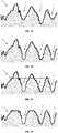
Figure 1A schematically illustrates a profile of a road surface prior to the application of a process according to the present invention; -
Figure 1B schematically illustrates a profile of a road surface after the first step of a process according to the present invention; -
Figure 1C schematically illustrates a profile of a road surface and a plane on which to perform the second stage (smoothing) of a process according to the present invention; -
Figure 1D schematically illustrates a profile of a road surface at the termination of a process according to the present invention (after the smoothing); -
Figure 2 shows a diagram of the Helmholtz Resonator Model; -
Figure 3 illustrates a progression of the profile of the road surface after treatment with a process according to the present invention; -
Figure 4 is a graph that shows the values of the mean profile depth (MPD) before, during and after treatment with a process according to the present invention, with three different types of asphalt; -
Figure 5 illustrates a progression of the MPD value along a section of road surface following treatment with a process according to the present invention; -
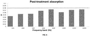
Figure 6 shows values of the coefficient of absorption (or CA) measured on a road surface after treatment with a process according to the present invention as a function of varying the frequency band; -
Figure 7 shows examples of means for increasing the mean profile depth (MPD) in a treatment apparatus according to the present invention; and -
Figure 8 shows, by way of example, means for reducing the mean profile depth (MPD) in a treatment apparatus according to the present invention. - The present invention will hereinafter be described with reference to the above indicated figures.
- The term mean profile depth, or MPD, refers to the average depth of the road surface calculated as the arithmetic mean of the individual depths of such a surface. A road surface, which is the object of the treatment according to the present invention, is characterized by a mean profile depth (MPD) of a predetermined value.
- The term coefficient of absorption, or CA, refers to the ability of a material to absorb sound energy and wherein the value is between 0 and 1.00, where zero represents an absolute lack of absorption (complete reflection) and 1.00 represents the total absorption of incident sound.
- Overall, the Figures from 1A to 1 D schematically illustrate the steps of a treatment process of a road surface S according to the present invention; these steps are:
- increasing the mean profile depth MPD of the surface S in generating new cavities V and/or in accentuating pre-existing cavities V on the surface S; and
- reducing the mean profile depth MPD of the surface S in order to return it to approximately the predetermined value in performing the smoothing of said surface S such as to reduce the asperities that emerge from the surface S.
- These cavities V function according to the Helmholtz Resonator model illustrated in
Figure 2 , resulting in an increase in the acoustic coefficient of absorption CA of the surface S. The system described by this model is equivalent to that comprising an oscillating mass (air within the neck D), an elastic element (air within the cavity V) and a damping element (the friction of the air against the walls of the neck D). Such a system behaves as a set of Helmholtz resonators insofar as it is the holes that are producing a sound absorption effect based upon the principle of Helmholtz. Such a resonator is able to dissipate acoustic energy as heat by the effect of viscous friction, which is generated due to the oscillations of the air contained within the neck D and of the friction of the air with the walls of the neck D itself. - With initial reference to
Figure 1A , this shows schematically a formation of the road surface before applying the method according to the present invention. As is known, the laying of asphalt results in an irregular alternation of ridges and valleys upon the surface profile of the road surface S; the valleys correspond to the profile view of the cavities V within the road surface S. - According to the present invention, the first part of the methodology consists in increasing the mean profile depth MPD of the surface S and this can be implemented by accentuating the pre-existing cavities V upon the surface S and/or in generating new cavities T.
- According to a preferred embodiment of the invention, such a result can be obtained in directing a jet of fluid J at high pressure and thereby generating cavities V, and/or in accentuating pre-existing cavities V within the texture of the surface S. Such cavities V have the function of absorbing the acoustic waves according to the Helmholtz Resonator model explained above.
- As can in fact be appreciated from
Figure 1B , the pre-existing cavities V show a greater depth, therefore a greater MPD value, due to the jet of fluid J. The dotted line indicates the initial profile of each cavity V, i.e., the profile shown inFigure 1A . - Preferably, the jet of fluid J is at a pressure of between about 1,500 bar and 3,500 bar. More preferably a pressure of about 2500 bar is used.
- According to a most preferred embodiment, the fluid used is water; in this case, this first step of the process will be called "Jet water." It is however to be understood that such an indication should not be considered in a limiting sense.
- In
Figure 1C , the dotted line P indicates the plane on which the second step of the treatment is performed, i.e., the smoothing. This process renders the surface S completely planar, making it contemporaneously possible to maintain the cavities V obtained by means of the first treatment, for example the jet water. - The result of this step of the process is appreciable in
Figure 1D : having cut away part of the surface asperities of the surface S, the mean profile depth MPD has been accordingly reduced. In this way, one part of the acoustic waves will be absorbed by the cavities V of the surface S and the other part will be reflected by the "flat" part (the cut part). - This effect produces acoustic absorption at high frequencies and reflection of the lower frequencies. From the graph of
Figure 3 , the measurement can be observed of a progression of the profile of the surface S along a section X of road surface, similarly to that exemplified inFigures 1A to 1D . - A graph is shown in
Figure 4 that instead reports the MPD values: three curves A, B and C are shown here that vary depending upon the type of asphalt; for each type of asphalt, prior to being treated, the respective MPD value is measured subsequent to the first step (for example, after the water jet) and at the end of the second step of smoothing (i.e., at the end of the complete treatment process); the dotted line represents the limiting MPD value imposed by the ISO 10844 standard. - In
Figure 5 it is possible to appreciate the progression of the MPD value measured along a section X of road surface traveled by a vehicle for a road surface treated with a process according to the present invention; it can be seen how the MPD value falls entirely within the range of values accepted by the aforementioned ISO standard (between 0.3 and 0.7 mm). - In
Figure 6 , instead, the CA values are shown measured as a function of varying the frequency band of the stress exerted by the tyre, for a vehicle that travels along a road surface treated with a process according to the present invention; these also are falling within the limits of acceptability (<8%) according to the aforementioned ISO standard. - A process according to the present invention, as described heretofore in the possible embodiments thereof, may also envisage that both the increase and the reduction in the mean profile depth (MPD) are between 60% and 120% of the initial predetermined value.
- More particularly, the process described, according to the present invention, can provide for both the increase and the reduction in the mean profile depth (MPD) being approximately 100% of the initial predetermined value.
- A further object of the present invention is that of describing an apparatus for the treatment of a road surface S having a mean profile depth MPD of a predetermined value. Such an apparatus is able to perform a treatment process as described thus far and comprises:
- means for increasing the mean profile depth MPD of the surface S generating new cavities V and/or accentuating pre-existing cavities V upon the surface S;
- means for reducing the mean profile depth MPD of the surface S in order to return it to approximately the predetermined value in performing the smoothing of said surface S such as to reduce the asperities that emerge from the surface S.
-
Figure 7 shows an exemplary design of a possible embodiment of the means for increasing the depth MPD for an apparatus according to the present invention. The means to increase the MPD may be a means of the type conventionally used within the industry. In the example shown inFigure 7 , the means for increasing the MPD are implemented in the form of alance 10 for delivering high pressure fluid onto the asphalt in order to generate new cavities V and/or to accentuate pre-existing cavities V upon the surface S. - In a preferred embodiment according to a treatment apparatus of the present invention, the means for increasing the MPD comprise a
movement mechanism 11 which allows thelance 10 for high pressure fluid to slide along at least one axis on a plane parallel to the surface S of the road surface to be treated. - In an even more preferred embodiment according to a treatment apparatus of the present invention, the means for increasing the MPD comprise a
movement mechanism 11 which allows thelance 10 for high pressure fluid to be independently, and possibly also contemporaneously, moved along two axes orthogonal therebetween on a plane parallel to the surface S of the road surface to be treated. Moreover, such amovement mechanism 11, according to the latter two embodiments, may provide for anergonomic seat 12 in order to accommodate the operator assigned to the maneuvering and operation of the lance for high pressure fluid in such a way as to facilitate the performance of tasks. -
Figure 8 shows an exemplary design of a possible embodiment of the means for reducing the MPD for an apparatus according to the present invention. In the example shown inFigure 8 , such means for reducing the MPD can be a sandingmachine 13 of the type conventionally used within the industry. - In a further embodiment, a treatment apparatus according to the present invention comprises within a single system the means to increase the MPD and the means to reduce the MPD.
- In a further preferred embodiment, a treatment apparatus according to the present invention comprises within a single system the means to increase the MPD illustrated in
Figure 7 and the means to reduce the MPD illustrated inFigure 8 . Purely by way of example, a treatment apparatus according to that described heretofore can be implemented in the form of a vehicle (such as, for example, a car or a truck), which, at the front, provides for means to increase the MPD, for example in the form alance 10 for high pressure fluid, and, at the rear, means for reducing the MPD and for performing smoothing processes, for example in the form of a sandingmachine 13. - The present invention has heretofore been described with reference to the preferred embodiments thereof. It is intended that each of the technical characteristics implemented in the preferred embodiments described herein, purely by way of example, can advantageously be combined, in ways other than that described heretofore, also with other characteristics in order to give form to other embodiments which also belong to the same inventive nucleus and that all fall within the scope of protection afforded by the claims recited hereinafter.
Claims (9)
- Treatment process for the roughness of a road surface (S) having a mean profile depth (MPD) of a predetermined value for increasing the acoustic coefficient of absorption of the road surface (S), comprising the following steps:- increasing the mean profile depth (MPD) of said surface (S) in generating new cavities (V) and/or in accentuating pre-existing cavities (V) upon the surface (S);- reducing the mean profile depth (MPD) of said surface (S), in order to return it to approximately the predetermined value, in performing a smoothing of said surface (S) such as to reduce the asperities that emerge from said surface (S).wherein said cavities (V), functioning as Helmholtz resonators, determine an increase in the acoustic coefficient of absorption (CA) of the surface (S),
wherein said step of increasing the mean profile depth (MPD) comprises the directing of a jet of fluid (J) at high pressure towards said surface (S),
wherein said mean profile depth (MPD) is defined by the arithmetic mean of individual values of depth of said road surface (S). - Process according to claim 1, wherein said increase and said reduction in the mean profile depth (MPD) are between 60% and 120% of the initial predetermined value.
- Process according to claim 2, wherein said increase and said reduction in the mean profile depth (MPD) are approximately 100% of the initial predetermined value.
- Process according to one of claims 1 to 3, wherein said jet of fluid (J) is at a pressure of between 1,500 bar and 3,500 bar, preferably equal to about 2500 bar.
- Process according to one of the claims from 1 to 4, wherein said fluid is water.
- Treatment apparatus according to a process of one of the claims from 1 to 5, for the roughness of a road surface (S) having a mean profile depth (MPD) of a predetermined value, comprising:- means for increasing the mean profile depth (MPD) of said surface (S) in generating new cavities (V) and/or in accentuating pre-existing cavities (V) upon the surface (S);- means for reducing the mean profile depth (MPD) of said surface S, in order to return it to approximately the predetermined value, in implementing a smoothing of said surface (S) such as to reduce the asperities that emerge from said surface (S).
- Apparatus according to claim 6, wherein said means for increasing the mean profile depth (MPD) comprise a lance (10) for high pressure fluid.
- Apparatus according to claim 7, wherein said lance (10) is suitable for producing a jet of fluid at a pressure of between about 1,500 bar and 3,500 bar, preferably equal to about 2,500 bar.
- Apparatus according to one of the claims from 6 to 8, wherein said means for reducing the mean profile depth (MPD) comprise a sanding machine (13).
Applications Claiming Priority (1)
| Application Number | Priority Date | Filing Date | Title |
|---|---|---|---|
| IT102018000021352A IT201800021352A1 (en) | 2018-12-28 | 2018-12-28 | PROCEDURE AND APPARATUS FOR THE TREATMENT OF ROUGH ROAD SURFACES |
Publications (2)
| Publication Number | Publication Date |
|---|---|
| EP3690140A1 true EP3690140A1 (en) | 2020-08-05 |
| EP3690140B1 EP3690140B1 (en) | 2021-11-17 |
Family
ID=66379985
Family Applications (1)
| Application Number | Title | Priority Date | Filing Date |
|---|---|---|---|
| EP19216982.9A Active EP3690140B1 (en) | 2018-12-28 | 2019-12-17 | Process and apparatus for the treatment of the roughness of a road surface |
Country Status (3)
| Country | Link |
|---|---|
| EP (1) | EP3690140B1 (en) |
| ES (1) | ES2900659T3 (en) |
| IT (1) | IT201800021352A1 (en) |
Cited By (1)
| Publication number | Priority date | Publication date | Assignee | Title |
|---|---|---|---|---|
| EP4257749A1 (en) * | 2022-04-05 | 2023-10-11 | OAT green tech solutions GmbH | Method for producing a road surface with reduced emission of microplastics |
Citations (3)
| Publication number | Priority date | Publication date | Assignee | Title |
|---|---|---|---|---|
| DE29922773U1 (en) * | 1998-12-30 | 2000-05-25 | Blastrak-Morava, spol. s.r.o., Brno | Road surface |
| WO2004067847A1 (en) | 2003-01-27 | 2004-08-12 | Blastrak_Morava, Spol. S R.O. | Method of repairing defects of a wearing course of road surface, particularly permanent deformations of its surface and roughness loss |
| US20080193214A1 (en) | 2007-02-13 | 2008-08-14 | Hall David R | Method for Adding Foaming Agents to Pavement Aggregate |
-
2018
- 2018-12-28 IT IT102018000021352A patent/IT201800021352A1/en unknown
-
2019
- 2019-12-17 EP EP19216982.9A patent/EP3690140B1/en active Active
- 2019-12-17 ES ES19216982T patent/ES2900659T3/en active Active
Patent Citations (3)
| Publication number | Priority date | Publication date | Assignee | Title |
|---|---|---|---|---|
| DE29922773U1 (en) * | 1998-12-30 | 2000-05-25 | Blastrak-Morava, spol. s.r.o., Brno | Road surface |
| WO2004067847A1 (en) | 2003-01-27 | 2004-08-12 | Blastrak_Morava, Spol. S R.O. | Method of repairing defects of a wearing course of road surface, particularly permanent deformations of its surface and roughness loss |
| US20080193214A1 (en) | 2007-02-13 | 2008-08-14 | Hall David R | Method for Adding Foaming Agents to Pavement Aggregate |
Cited By (1)
| Publication number | Priority date | Publication date | Assignee | Title |
|---|---|---|---|---|
| EP4257749A1 (en) * | 2022-04-05 | 2023-10-11 | OAT green tech solutions GmbH | Method for producing a road surface with reduced emission of microplastics |
Also Published As
| Publication number | Publication date |
|---|---|
| IT201800021352A1 (en) | 2020-06-28 |
| ES2900659T3 (en) | 2022-03-17 |
| EP3690140B1 (en) | 2021-11-17 |
Similar Documents
| Publication | Publication Date | Title |
|---|---|---|
| Wang et al. | Study on the system matching of ultrasonic vibration assisted grinding for hard and brittle materials processing | |
| Buj-Corral et al. | Acoustic emission analysis for the detection of appropriate cutting operations in honing processes | |
| CN105307817B (en) | For preparing and the method and facility on coating workpieces surface | |
| JP5149204B2 (en) | A method to clarify the characteristics of fatigue strength of a part from the contour of its surface | |
| Hartikainen et al. | Frequency-wise correlation of the power spectral density of asphalt surface roughness and tire wet friction | |
| EP3690140B1 (en) | Process and apparatus for the treatment of the roughness of a road surface | |
| EP3060721B1 (en) | Grinding motor and method of operating the same for rail applications | |
| JP2007067110A5 (en) | ||
| WO2004101297A1 (en) | Tire designing method and program | |
| JPH07195364A (en) | Method and apparatus for pretreatment for adhesion of vulcanized rubber surface | |
| Wang et al. | Effects of inclination angles of disc cutter on machining quality of Nomex honeycomb core in ultrasonic cutting | |
| Li et al. | An artificial neural network model to predict tread pattern-related tire noise | |
| Shiliang et al. | Investigation on surface micro-crack evaluation of engineering ceramics by rotary ultrasonic grinding machining | |
| JPH07299390A (en) | Super high pressure fan jet nozzle | |
| Gardziejczyk | Influence of road pavement macrotexture on tyre/road noise of vehicles | |
| Rajczyk et al. | The influence of surface topography on the safety of road and utility surfaces | |
| Wang et al. | Profile cutting on alumina ceramics by abrasive waterjet. Part 2: cutting performance models | |
| Wang | Depth of cut models for multipass abrasive waterjet cutting of alumina ceramics with nozzle oscillation | |
| US20200164479A1 (en) | Method of abrading a test track with a bituminous surface | |
| US2514626A (en) | Smoothing or finishing trowel | |
| Azlan et al. | Experimental investigation of surface roughness using ultrasonic assisted machining of hardened steel | |
| JP6827342B2 (en) | Compaction machine | |
| Haider et al. | Road traffic noise emission: recent developments and future prospects | |
| JP6855911B2 (en) | Evaluation method of tire performance on snow | |
| Kim et al. | Noise reduction capacity of a composite pavement system |
Legal Events
| Date | Code | Title | Description |
|---|---|---|---|
| PUAI | Public reference made under article 153(3) epc to a published international application that has entered the european phase |
Free format text: ORIGINAL CODE: 0009012 |
|
| STAA | Information on the status of an ep patent application or granted ep patent |
Free format text: STATUS: THE APPLICATION HAS BEEN PUBLISHED |
|
| AK | Designated contracting states |
Kind code of ref document: A1 Designated state(s): AL AT BE BG CH CY CZ DE DK EE ES FI FR GB GR HR HU IE IS IT LI LT LU LV MC MK MT NL NO PL PT RO RS SE SI SK SM TR |
|
| AX | Request for extension of the european patent |
Extension state: BA ME |
|
| STAA | Information on the status of an ep patent application or granted ep patent |
Free format text: STATUS: REQUEST FOR EXAMINATION WAS MADE |
|
| 17P | Request for examination filed |
Effective date: 20210202 |
|
| RBV | Designated contracting states (corrected) |
Designated state(s): AL AT BE BG CH CY CZ DE DK EE ES FI FR GB GR HR HU IE IS IT LI LT LU LV MC MK MT NL NO PL PT RO RS SE SI SK SM TR |
|
| GRAP | Despatch of communication of intention to grant a patent |
Free format text: ORIGINAL CODE: EPIDOSNIGR1 |
|
| STAA | Information on the status of an ep patent application or granted ep patent |
Free format text: STATUS: GRANT OF PATENT IS INTENDED |
|
| INTG | Intention to grant announced |
Effective date: 20210607 |
|
| GRAS | Grant fee paid |
Free format text: ORIGINAL CODE: EPIDOSNIGR3 |
|
| GRAA | (expected) grant |
Free format text: ORIGINAL CODE: 0009210 |
|
| STAA | Information on the status of an ep patent application or granted ep patent |
Free format text: STATUS: THE PATENT HAS BEEN GRANTED |
|
| AK | Designated contracting states |
Kind code of ref document: B1 Designated state(s): AL AT BE BG CH CY CZ DE DK EE ES FI FR GB GR HR HU IE IS IT LI LT LU LV MC MK MT NL NO PL PT RO RS SE SI SK SM TR |
|
| REG | Reference to a national code |
Ref country code: GB Ref legal event code: FG4D |
|
| REG | Reference to a national code |
Ref country code: DE Ref legal event code: R096 Ref document number: 602019009360 Country of ref document: DE |
|
| REG | Reference to a national code |
Ref country code: IE Ref legal event code: FG4D |
|
| REG | Reference to a national code |
Ref country code: AT Ref legal event code: REF Ref document number: 1448152 Country of ref document: AT Kind code of ref document: T Effective date: 20211215 |
|
| REG | Reference to a national code |
Ref country code: LT Ref legal event code: MG9D |
|
| REG | Reference to a national code |
Ref country code: ES Ref legal event code: FG2A Ref document number: 2900659 Country of ref document: ES Kind code of ref document: T3 Effective date: 20220317 |
|
| REG | Reference to a national code |
Ref country code: NL Ref legal event code: MP Effective date: 20211117 |
|
| REG | Reference to a national code |
Ref country code: AT Ref legal event code: MK05 Ref document number: 1448152 Country of ref document: AT Kind code of ref document: T Effective date: 20211117 |
|
| PG25 | Lapsed in a contracting state [announced via postgrant information from national office to epo] |
Ref country code: RS Free format text: LAPSE BECAUSE OF FAILURE TO SUBMIT A TRANSLATION OF THE DESCRIPTION OR TO PAY THE FEE WITHIN THE PRESCRIBED TIME-LIMIT Effective date: 20211117 Ref country code: LT Free format text: LAPSE BECAUSE OF FAILURE TO SUBMIT A TRANSLATION OF THE DESCRIPTION OR TO PAY THE FEE WITHIN THE PRESCRIBED TIME-LIMIT Effective date: 20211117 Ref country code: FI Free format text: LAPSE BECAUSE OF FAILURE TO SUBMIT A TRANSLATION OF THE DESCRIPTION OR TO PAY THE FEE WITHIN THE PRESCRIBED TIME-LIMIT Effective date: 20211117 Ref country code: BG Free format text: LAPSE BECAUSE OF FAILURE TO SUBMIT A TRANSLATION OF THE DESCRIPTION OR TO PAY THE FEE WITHIN THE PRESCRIBED TIME-LIMIT Effective date: 20220217 Ref country code: AT Free format text: LAPSE BECAUSE OF FAILURE TO SUBMIT A TRANSLATION OF THE DESCRIPTION OR TO PAY THE FEE WITHIN THE PRESCRIBED TIME-LIMIT Effective date: 20211117 |
|
| PG25 | Lapsed in a contracting state [announced via postgrant information from national office to epo] |
Ref country code: IS Free format text: LAPSE BECAUSE OF FAILURE TO SUBMIT A TRANSLATION OF THE DESCRIPTION OR TO PAY THE FEE WITHIN THE PRESCRIBED TIME-LIMIT Effective date: 20220317 Ref country code: SE Free format text: LAPSE BECAUSE OF FAILURE TO SUBMIT A TRANSLATION OF THE DESCRIPTION OR TO PAY THE FEE WITHIN THE PRESCRIBED TIME-LIMIT Effective date: 20211117 Ref country code: PT Free format text: LAPSE BECAUSE OF FAILURE TO SUBMIT A TRANSLATION OF THE DESCRIPTION OR TO PAY THE FEE WITHIN THE PRESCRIBED TIME-LIMIT Effective date: 20220317 Ref country code: PL Free format text: LAPSE BECAUSE OF FAILURE TO SUBMIT A TRANSLATION OF THE DESCRIPTION OR TO PAY THE FEE WITHIN THE PRESCRIBED TIME-LIMIT Effective date: 20211117 Ref country code: NO Free format text: LAPSE BECAUSE OF FAILURE TO SUBMIT A TRANSLATION OF THE DESCRIPTION OR TO PAY THE FEE WITHIN THE PRESCRIBED TIME-LIMIT Effective date: 20220217 Ref country code: NL Free format text: LAPSE BECAUSE OF FAILURE TO SUBMIT A TRANSLATION OF THE DESCRIPTION OR TO PAY THE FEE WITHIN THE PRESCRIBED TIME-LIMIT Effective date: 20211117 Ref country code: LV Free format text: LAPSE BECAUSE OF FAILURE TO SUBMIT A TRANSLATION OF THE DESCRIPTION OR TO PAY THE FEE WITHIN THE PRESCRIBED TIME-LIMIT Effective date: 20211117 Ref country code: HR Free format text: LAPSE BECAUSE OF FAILURE TO SUBMIT A TRANSLATION OF THE DESCRIPTION OR TO PAY THE FEE WITHIN THE PRESCRIBED TIME-LIMIT Effective date: 20211117 Ref country code: GR Free format text: LAPSE BECAUSE OF FAILURE TO SUBMIT A TRANSLATION OF THE DESCRIPTION OR TO PAY THE FEE WITHIN THE PRESCRIBED TIME-LIMIT Effective date: 20220218 |
|
| PG25 | Lapsed in a contracting state [announced via postgrant information from national office to epo] |
Ref country code: SM Free format text: LAPSE BECAUSE OF FAILURE TO SUBMIT A TRANSLATION OF THE DESCRIPTION OR TO PAY THE FEE WITHIN THE PRESCRIBED TIME-LIMIT Effective date: 20211117 Ref country code: SK Free format text: LAPSE BECAUSE OF FAILURE TO SUBMIT A TRANSLATION OF THE DESCRIPTION OR TO PAY THE FEE WITHIN THE PRESCRIBED TIME-LIMIT Effective date: 20211117 Ref country code: RO Free format text: LAPSE BECAUSE OF FAILURE TO SUBMIT A TRANSLATION OF THE DESCRIPTION OR TO PAY THE FEE WITHIN THE PRESCRIBED TIME-LIMIT Effective date: 20211117 Ref country code: EE Free format text: LAPSE BECAUSE OF FAILURE TO SUBMIT A TRANSLATION OF THE DESCRIPTION OR TO PAY THE FEE WITHIN THE PRESCRIBED TIME-LIMIT Effective date: 20211117 Ref country code: DK Free format text: LAPSE BECAUSE OF FAILURE TO SUBMIT A TRANSLATION OF THE DESCRIPTION OR TO PAY THE FEE WITHIN THE PRESCRIBED TIME-LIMIT Effective date: 20211117 Ref country code: CZ Free format text: LAPSE BECAUSE OF FAILURE TO SUBMIT A TRANSLATION OF THE DESCRIPTION OR TO PAY THE FEE WITHIN THE PRESCRIBED TIME-LIMIT Effective date: 20211117 |
|
| REG | Reference to a national code |
Ref country code: DE Ref legal event code: R097 Ref document number: 602019009360 Country of ref document: DE |
|
| PG25 | Lapsed in a contracting state [announced via postgrant information from national office to epo] |
Ref country code: MC Free format text: LAPSE BECAUSE OF FAILURE TO SUBMIT A TRANSLATION OF THE DESCRIPTION OR TO PAY THE FEE WITHIN THE PRESCRIBED TIME-LIMIT Effective date: 20211117 |
|
| PLBE | No opposition filed within time limit |
Free format text: ORIGINAL CODE: 0009261 |
|
| STAA | Information on the status of an ep patent application or granted ep patent |
Free format text: STATUS: NO OPPOSITION FILED WITHIN TIME LIMIT |
|
| REG | Reference to a national code |
Ref country code: BE Ref legal event code: MM Effective date: 20211231 |
|
| 26N | No opposition filed |
Effective date: 20220818 |
|
| PG25 | Lapsed in a contracting state [announced via postgrant information from national office to epo] |
Ref country code: LU Free format text: LAPSE BECAUSE OF NON-PAYMENT OF DUE FEES Effective date: 20211217 Ref country code: IE Free format text: LAPSE BECAUSE OF NON-PAYMENT OF DUE FEES Effective date: 20211217 Ref country code: AL Free format text: LAPSE BECAUSE OF FAILURE TO SUBMIT A TRANSLATION OF THE DESCRIPTION OR TO PAY THE FEE WITHIN THE PRESCRIBED TIME-LIMIT Effective date: 20211117 |
|
| PG25 | Lapsed in a contracting state [announced via postgrant information from national office to epo] |
Ref country code: SI Free format text: LAPSE BECAUSE OF FAILURE TO SUBMIT A TRANSLATION OF THE DESCRIPTION OR TO PAY THE FEE WITHIN THE PRESCRIBED TIME-LIMIT Effective date: 20211117 Ref country code: BE Free format text: LAPSE BECAUSE OF NON-PAYMENT OF DUE FEES Effective date: 20211231 |
|
| PG25 | Lapsed in a contracting state [announced via postgrant information from national office to epo] |
Ref country code: IT Free format text: LAPSE BECAUSE OF FAILURE TO SUBMIT A TRANSLATION OF THE DESCRIPTION OR TO PAY THE FEE WITHIN THE PRESCRIBED TIME-LIMIT Effective date: 20211117 |
|
| PG25 | Lapsed in a contracting state [announced via postgrant information from national office to epo] |
Ref country code: CY Free format text: LAPSE BECAUSE OF FAILURE TO SUBMIT A TRANSLATION OF THE DESCRIPTION OR TO PAY THE FEE WITHIN THE PRESCRIBED TIME-LIMIT Effective date: 20211117 |
|
| PG25 | Lapsed in a contracting state [announced via postgrant information from national office to epo] |
Ref country code: HU Free format text: LAPSE BECAUSE OF FAILURE TO SUBMIT A TRANSLATION OF THE DESCRIPTION OR TO PAY THE FEE WITHIN THE PRESCRIBED TIME-LIMIT; INVALID AB INITIO Effective date: 20191217 |
|
| REG | Reference to a national code |
Ref country code: CH Ref legal event code: PL |
|
| PG25 | Lapsed in a contracting state [announced via postgrant information from national office to epo] |
Ref country code: LI Free format text: LAPSE BECAUSE OF NON-PAYMENT OF DUE FEES Effective date: 20221231 Ref country code: CH Free format text: LAPSE BECAUSE OF NON-PAYMENT OF DUE FEES Effective date: 20221231 |
|
| PG25 | Lapsed in a contracting state [announced via postgrant information from national office to epo] |
Ref country code: MK Free format text: LAPSE BECAUSE OF FAILURE TO SUBMIT A TRANSLATION OF THE DESCRIPTION OR TO PAY THE FEE WITHIN THE PRESCRIBED TIME-LIMIT Effective date: 20211117 |
|
| PG25 | Lapsed in a contracting state [announced via postgrant information from national office to epo] |
Ref country code: TR Free format text: LAPSE BECAUSE OF FAILURE TO SUBMIT A TRANSLATION OF THE DESCRIPTION OR TO PAY THE FEE WITHIN THE PRESCRIBED TIME-LIMIT Effective date: 20211117 |
|
| PG25 | Lapsed in a contracting state [announced via postgrant information from national office to epo] |
Ref country code: MT Free format text: LAPSE BECAUSE OF FAILURE TO SUBMIT A TRANSLATION OF THE DESCRIPTION OR TO PAY THE FEE WITHIN THE PRESCRIBED TIME-LIMIT Effective date: 20211117 |
|
| PGFP | Annual fee paid to national office [announced via postgrant information from national office to epo] |
Ref country code: DE Payment date: 20251126 Year of fee payment: 7 |
|
| PGFP | Annual fee paid to national office [announced via postgrant information from national office to epo] |
Ref country code: GB Payment date: 20251119 Year of fee payment: 7 |
|
| PGFP | Annual fee paid to national office [announced via postgrant information from national office to epo] |
Ref country code: FR Payment date: 20251120 Year of fee payment: 7 |
|
| PGFP | Annual fee paid to national office [announced via postgrant information from national office to epo] |
Ref country code: ES Payment date: 20260102 Year of fee payment: 7 |