EP3690118A1 - Dual drain system with y-hose - Google Patents
Dual drain system with y-hose Download PDFInfo
- Publication number
- EP3690118A1 EP3690118A1 EP20153259.5A EP20153259A EP3690118A1 EP 3690118 A1 EP3690118 A1 EP 3690118A1 EP 20153259 A EP20153259 A EP 20153259A EP 3690118 A1 EP3690118 A1 EP 3690118A1
- Authority
- EP
- European Patent Office
- Prior art keywords
- drain
- recirculating
- appliance
- valve
- coupled
- Prior art date
- Legal status (The legal status is an assumption and is not a legal conclusion. Google has not performed a legal analysis and makes no representation as to the accuracy of the status listed.)
- Withdrawn
Links
Images


Classifications
-
- D—TEXTILES; PAPER
- D06—TREATMENT OF TEXTILES OR THE LIKE; LAUNDERING; FLEXIBLE MATERIALS NOT OTHERWISE PROVIDED FOR
- D06F—LAUNDERING, DRYING, IRONING, PRESSING OR FOLDING TEXTILE ARTICLES
- D06F39/00—Details of washing machines not specific to a single type of machines covered by groups D06F9/00 - D06F27/00
- D06F39/08—Liquid supply or discharge arrangements
- D06F39/083—Liquid discharge or recirculation arrangements
-
- A—HUMAN NECESSITIES
- A47—FURNITURE; DOMESTIC ARTICLES OR APPLIANCES; COFFEE MILLS; SPICE MILLS; SUCTION CLEANERS IN GENERAL
- A47L—DOMESTIC WASHING OR CLEANING; SUCTION CLEANERS IN GENERAL
- A47L15/00—Washing or rinsing machines for crockery or tableware
- A47L15/42—Details
- A47L15/4214—Water supply, recirculation or discharge arrangements; Devices therefor
- A47L15/4219—Water recirculation
-
- A—HUMAN NECESSITIES
- A47—FURNITURE; DOMESTIC ARTICLES OR APPLIANCES; COFFEE MILLS; SPICE MILLS; SUCTION CLEANERS IN GENERAL
- A47L—DOMESTIC WASHING OR CLEANING; SUCTION CLEANERS IN GENERAL
- A47L15/00—Washing or rinsing machines for crockery or tableware
- A47L15/42—Details
- A47L15/4214—Water supply, recirculation or discharge arrangements; Devices therefor
- A47L15/4223—Devices for water discharge, e.g. devices to prevent siphoning, non-return valves
-
- D—TEXTILES; PAPER
- D06—TREATMENT OF TEXTILES OR THE LIKE; LAUNDERING; FLEXIBLE MATERIALS NOT OTHERWISE PROVIDED FOR
- D06F—LAUNDERING, DRYING, IRONING, PRESSING OR FOLDING TEXTILE ARTICLES
- D06F39/00—Details of washing machines not specific to a single type of machines covered by groups D06F9/00 - D06F27/00
- D06F39/20—Arrangements for water recovery
-
- F—MECHANICAL ENGINEERING; LIGHTING; HEATING; WEAPONS; BLASTING
- F16—ENGINEERING ELEMENTS AND UNITS; GENERAL MEASURES FOR PRODUCING AND MAINTAINING EFFECTIVE FUNCTIONING OF MACHINES OR INSTALLATIONS; THERMAL INSULATION IN GENERAL
- F16K—VALVES; TAPS; COCKS; ACTUATING-FLOATS; DEVICES FOR VENTING OR AERATING
- F16K11/00—Multiple-way valves, e.g. mixing valves; Pipe fittings incorporating such valves
- F16K11/10—Multiple-way valves, e.g. mixing valves; Pipe fittings incorporating such valves with two or more closure members not moving as a unit
- F16K11/20—Multiple-way valves, e.g. mixing valves; Pipe fittings incorporating such valves with two or more closure members not moving as a unit operated by separate actuating members
- F16K11/24—Multiple-way valves, e.g. mixing valves; Pipe fittings incorporating such valves with two or more closure members not moving as a unit operated by separate actuating members with an electromagnetically-operated valve, e.g. for washing machines
-
- F—MECHANICAL ENGINEERING; LIGHTING; HEATING; WEAPONS; BLASTING
- F16—ENGINEERING ELEMENTS AND UNITS; GENERAL MEASURES FOR PRODUCING AND MAINTAINING EFFECTIVE FUNCTIONING OF MACHINES OR INSTALLATIONS; THERMAL INSULATION IN GENERAL
- F16L—PIPES; JOINTS OR FITTINGS FOR PIPES; SUPPORTS FOR PIPES, CABLES OR PROTECTIVE TUBING; MEANS FOR THERMAL INSULATION IN GENERAL
- F16L41/00—Branching pipes; Joining pipes to walls
- F16L41/02—Branch units, e.g. made in one piece, welded, riveted
- F16L41/023—Y- pieces
-
- Y—GENERAL TAGGING OF NEW TECHNOLOGICAL DEVELOPMENTS; GENERAL TAGGING OF CROSS-SECTIONAL TECHNOLOGIES SPANNING OVER SEVERAL SECTIONS OF THE IPC; TECHNICAL SUBJECTS COVERED BY FORMER USPC CROSS-REFERENCE ART COLLECTIONS [XRACs] AND DIGESTS
- Y10—TECHNICAL SUBJECTS COVERED BY FORMER USPC
- Y10T—TECHNICAL SUBJECTS COVERED BY FORMER US CLASSIFICATION
- Y10T137/00—Fluid handling
- Y10T137/8593—Systems
- Y10T137/877—With flow control means for branched passages
- Y10T137/87877—Single inlet with multiple distinctly valved outlets
Definitions
- the present disclosure generally relates to an appliance drain system, and more specifically, to a drain system for a washing machine.
- the disclosure provides for a drain system for an appliance.
- the drain system can include a Y-hose having a flexible end coupled to a supply of water from an appliance, a recirculating end, and a drain end, a recirculating valve having a recirculating inlet coupled to the recirculating end at a recirculating inlet side and a recirculating outlet coupled to a first hose at a recirculating outlet side, a drain valve spaced from the recirculating valve having a drain inlet coupled to the drain end at a drain inlet side and a drain outlet coupled to a second hose at a drain outlet side, a recirculating solenoid coupled to the recirculating valve on a recirculating solenoid side of the recirculating valve, and a drain solenoid coupled to the drain valve on a drain solenoid side of the drain valve.
- the disclosure provides for a drain system for an appliance.
- the drain system can include a Y-hose having a flexible end coupled to a supply of water from a tub, a recirculating end, and a drain end, a recirculating valve coupled with the recirculating end, a drain valve spaced from the recirculating valve and coupled with the drain end, and wherein the recirculating end and the drain end are connected via a continuous connecting wall defining a hollow arc.
- the disclosure provides for a drain system for an appliance.
- the drain system can include a Y-hose having a flexible end coupled to a supply of water from a tub, a recirculating end, and a drain end, a recirculating valve having a recirculating inlet rigidly coupled to the recirculating end at a recirculating inlet side and a recirculating outlet coupled to a first hose at a recirculating outlet side, a drain valve spaced from the recirculating valve having a drain inlet rigidly coupled to the drain end at a drain inlet side and a drain outlet coupled to a second hose at a drain outlet side, a recirculating solenoid coupled to the recirculating valve on a recirculating solenoid side of the recirculating valve, a drain solenoid coupled to the drain valve on a drain solenoid side of the drain valve, and wherein the recirculating outlet and the drain outlet are arranged on opposite sides of the recirculating valve and the drain valve and the first hose is
- the terms "upper,” “lower,” “right,” “left,” “rear,” “front,” “vertical,” “horizontal,” and derivatives thereof shall relate to the device as oriented in FIG. 1 .
- the device may assume various alternative orientations and step sequences, except where expressly specified to the contrary.
- the specific devices and processes illustrated in the attached drawings, and described in the following specification are simply exemplary embodiments of the inventive concepts defined in the appended claims. Hence, specific dimensions and other physical characteristics relating to the embodiments disclosed herein are not to be considered as limiting, unless the claims expressly state otherwise.
- the present disclosure provides various structures and components for a drain system for an appliance, such as a laundry appliance 10 shown in the illustrated embodiment.
- the drain system may include structures to facilitate the movement and evacuation of a supply of water from the appliance 10.
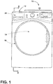
- FIG. 1 is a schematic illustration of a washing machine 10, which will not be described in detail except as necessary for a complete understanding of the disclosure.
- the washing machine 10 can include any suitable washing appliance, including a vertical-axis clothes washer, horizontal-axis clothes washer, combination washer-dryer, freestanding dishwasher, or under-counter dishwasher, in non-limiting examples on which various aspects of the presently disclosed drain system may be used.
- the washing machine 10, can include a cabinet 12 defining an interior of the washing machine 10, and a tub 14 provided within the cabinet 12 at least partially defining a treating chamber for receiving articles for treatment, such laundry.
- the tub 14 may be rotationally operable within the cabinet 12 that serves as a housing for the components of the washing machine 10.
- the washing machine 10 may further include a door 16 for accessing the tub 14 and one or more controls 18 for initiating a washing function of the washing machine 10.
- the controls 18 can be electrically coupled with a controller 20 located within the cabinet 12.
- the controller 20 can include the machine controller and any additional controllers provided for controlling any of the components of the washing machine 10. Many known types of controllers can be used for the controller 20. It is contemplated that the controller 20 is a microprocessor-based controller that implements control software and sends/receives one or more electrical signals to/from each of the various working components to effect the control software.
- FIG. 2 illustrates a partial cross-sectional view of the washing machine 10 taken along line II of FIG. 1 and showing only the lower portion of the appliance.
- the cabinet 12 can be a housing having a chassis and/or a frame, enclosing components typically found in a conventional washing machine, such as a motors, pumps, fluid lines, controls, sensors, transducers, and the like. Such components will not be described further herein except as necessary for a complete understanding of the disclosure.
- the tub 14 may be supported within the cabinet 12 by any suitable suspension system.
- the washing machine 10 can further include a recirculation system and drain system 100 for recirculating liquid back to the tub 14 and draining liquid from the tub 14, respectively.
- the drain system 100 may include an over-flow tube 30 for draining any over-flow liquid or suds that may occur.
- a coupler may be configured to couple the drain system 100 to a supply of water from the washing machine 10, which may include water from the tub 14.
- a supply of water can include fresh water, wash water, laundry chemistry, and the like.
- the coupler may be in the form of a Y-hose 110 having a flexible end 112 coupled to the tub 14.
- the flexible end 112 can be directly, or indirectly coupled to the tub 14 and may provide for sufficient tolerance of movement of the tub 14.
- the drain system 100 can further include a first hose 140 and a second hose 142, or dual hoses, configured to allow the passage of water from the Y-hose 110 for a variety of purposes such as draining, recirculating, or storing.
- the Y-hose 110 may be arranged towards a front of the washing machine 10, adjacent the door 16, such that the first hose 140 and second hose 142 are directed from the front of the washing machine 10 towards a rear of the washing machine 10.
- FIG. 3 is a perspective view of the drain system 100.
- the drain system 100 can further include a recirculating valve 130 spaced from a drain valve 144.
- the recirculating valve 130 and the drain valve 144 may be used for a variety of applications and are not limited to recirculating and draining only.
- the drain valve 144 may be fluidly coupled to a storage container.
- the recirculating valve 130 can include a body having at least a recirculating inlet side 134, a recirculating outlet side 138, and a recirculating solenoid side 156.
- the recirculating inlet side 134 may include an inlet port, or a recirculating inlet 132 and the recirculating outlet side 138 may include an outlet port, or a recirculating outlet 136.
- the drain valve 144 can include a body having at least a drain inlet side 148, a drain outlet side 152, and a drain solenoid side 160.
- the drain inlet side 148 may include an inlet port, or a drain inlet 146 and the drain outlet side 152 may include an outlet port, or a drain outlet 150.
- the recirculating valve 130 and the drain valve 144 include identical or mirrored configurations.
- the Y-hose 110 may further include a recirculating end 114 spaced from an outlet end, or drain end 116.
- the recirculating end 114 may be coupled with the recirculating inlet 132 and the drain end 116 may be coupled with the drain inlet 146 such that the recirculating valve 130 and the drain valve 144 are in fluid communication with the tub 14 via the Y-hose 110 and are arranged in a side-by-side configuration.
- the recirculating end 114 is rigidly coupled with the recirculating inlet 132 and the drain end 116 is rigidly coupled with the drain inlet 146 such that the spacing between the recirculating valve 130 and the drain valve 144 can be substantially maintained.
- first hose 140 may be coupled to the recirculating outlet 136 and the second hose 142 may be coupled to the drain outlet 150.
- the recirculating outlet 136 and the drain outlet 150 are arranged on opposite, or opposing sides of the recirculating valve 130 and the drain valve 144 such that the first hose 140 and the second hose 142 are arranged at outer sides of the drain system 100. It is also contemplated that the recirculating outlet 136 and the drain outlet 150 are the same, or corresponding sides, of the recirculating valve 130 and the drain valve 144 such that the first hose 140 and the second hose 142 are arranged in a side-by-side configuration.
- At least one of the first hose 140 and the second hose 142 may be coupled with the over-flow tube 30.
- the first hose 140 and the second hose 142 may include an outlet end 141 and an outlet end 143, respectively, downstream of the recirculating outlet 136 and the drain outlet 150, which may be coupled with further components of the washing machine 10 for draining water, recirculating water, storing water, etc.
- a recirculating solenoid 154 may be coupled to the recirculating valve 130 on the recirculating solenoid side 156 and a drain solenoid 158 may be coupled to the drain valve 144 on the drain solenoid side 160.
- the recirculating solenoid 154 and the drain solenoid 158 may be generally perpendicular to the recirculating outlet 136 and the drain outlet 150, respectively.
- the recirculating solenoid 154 and the drain solenoid 158 may be positioned near the front of the washing machine 10.
- the recirculating solenoid 154 and the drain solenoid 158 may be in electrical communication with the controller 20 in order to control water flow in and out of the recirculating valve 130 and the drain valve 144, respectively.
- the recirculating valve 130 and the drain valve 144 include gates, or valves, within their respective bodies, which are normally closed.
- the controller 20 may send a signal to one or both of the recirculating valve 130 and the drain valve 144 that triggers the "gate" to open such that water can flow into the recirculating inlet 132 and/or the drain inlet 146 and continue through to the recirculating outlet 136 and/or the drain outlet 150.
- the "gate" of the recirculating valve 130 or the drain valve 144 is closed, water flow is typically restricted.
- recirculating valve 130 and the drain valve 144 have been described as normally closed, any suitable valve and valve mechanism may be used and any combination thereof.
- the recirculating valve 130 and/or the drain valve 144 may be normally open, and may include a plunger actuator, a linear actuator, etc.
- FIG. 4 illustrates a front elevational view of the Y-hose 110.
- the recirculating end 114 and the drain end 116 may be connected, or fluidly coupled, via a continuous wall 122.
- the continuous wall 122 may be in the form of a hollow arc, or arch, where at least a portion of the continuous wall 122 includes an elliptical cross-section 120.
- the recirculating end 114 and the drain end 116 are a reflected duplication of each other.
- at least a portion of the recirculating end 114 and at least a portion of the drain end 116 may include the elliptical cross-section.
- FIG. 4A illustrates an exemplary cross-sectional view of line IVA showing the elliptical cross-section 120 of the continuous wall 122 having a hollow interior 128.
- the cross-section along line IVA on the recirculating end 114, and the corresponding cross-section on the drain end 116 may be the smallest cross-sectional area of the Y-hose 110.
- the flexible end 112 may further include corrugation 118 and may be positioned at a center 124 of the continuous wall 122.
- the flexible end 112 includes an apex 126 formed at the center 124 of the continuous wall 122.
- the continuous wall 122 typically cooperates with the flexible end 112 to produce a laminar flow of fluid through the recirculating end 114, the drain end 116, or both. Additionally, the continuous wall 122 includes a generally smooth arch that traverses between and separates the recirculating and drain ends 114, 116. This configuration of the Y-hose 110 produces the laminar flow of fluid that provides efficient draining of fluid from the tub 14 and to the recirculating and drain outlets 136, 150. The smooth arch of the continuous wall 122 also provides sufficient separation between the recirculating and drain ends 114, 116 so that the recirculating and drain valves 130, 144 can be positioned for convenient attachment to the Y-hose 110.
- the dual drain system 100 can be assembled from a single drain system as a field-installed kit.
- the washing machine 10 may originally include a single valve and a single hose.
- a second valve and a second hose may be installed.
- two new valves which may be identical, are installed such that a user can keep the original valve as a spare part.
- the dual drain system 100 may be factory installed.
- a drain system for an appliance includes a Y-hose having a flexible end coupled to a supply of water from an appliance, a recirculating end and a drain end.
- a recirculating valve has a recirculating inlet coupled to the recirculating end at a recirculating inlet side and a recirculating outlet coupled to a first hose at a recirculating outlet side.
- a drain valve is spaced from the recirculating valve and has a drain inlet coupled to the drain end at a drain inlet side and a drain outlet coupled to a second hose at a drain outlet side.
- a recirculating solenoid is coupled to the recirculating valve on a recirculating solenoid side of the recirculating valve and a drain solenoid is coupled to the drain valve on a drain solenoid side of the drain valve.
- the flexible end includes corrugation.
- the recirculating outlet and the drain outlet are arranged on opposite sides of the recirculating valve and the drain valve.
- the first hose is coupled to a recirculation hose fluidly coupled with the appliance.
- the at least a portion of the recirculating end and at least a portion of the drain end include a hollow elliptical cross section.
- the recirculating end and the drain end are connected via a continuous connecting wall defining an arc.
- the flexible end is positioned at a center of the continuous connecting wall.
- the recirculating end is spaced from the drain end.
- the recirculating outlet is generally perpendicular to the recirculating solenoid and the drain outlet is generally perpendicular to the drain solenoid.
- the recirculating solenoid and the drain solenoid are positioned towards a front of the appliance and the appliance includes a washing machine.
- the first and second hoses are directed towards a rear of the appliance and the appliance includes a washing machine.
- a drain system for an appliance includes a Y-hose having a flexible end coupled to a supply of water from a tub, a recirculating end and a drain end.
- a recirculating valve is coupled with the recirculating end and a drain valve is spaced from the recirculating valve and coupled with the drain end.
- the recirculating end and the drain end are connected via a continuous connecting wall defining a hollow arc.
- At least a portion of the arc comprises an elliptical cross section.
- the flexible end is positioned at a center of the continuous connecting wall.
- the recirculating valve includes a recirculating inlet coupled to the recirculating end at a recirculating inlet side and a recirculating outlet coupled to a first hose at a recirculating outlet side and the drain valve includes a drain inlet coupled to the drain end at a drain inlet side and a drain outlet coupled to a second hose at a drain outlet side.
- a recirculating solenoid is coupled to the recirculating valve on a recirculating solenoid side of the recirculating valve and a drain solenoid is coupled to the drain valve on a drain solenoid side of the drain valve.
- the flexible end comprises corrugation.
- the recirculating outlet and the drain outlet are arranged on opposite sides of the recirculating valve and the drain valve.
- the first hose is coupled to a recirculation hose fluidly coupled with the appliance.
- the at least a portion of the recirculating end and at least a portion of the drain end comprise a hollow elliptical cross section.
- the flexible end is positioned at a center of the continuous connecting wall.
- the recirculating end is spaced from the drain end.
- the recirculating outlet is generally perpendicular to the recirculating solenoid and the drain outlet is generally perpendicular to the drain solenoid.
- the recirculating solenoid and the drain solenoid are positioned towards a front of the appliance and the appliance comprises a washing machine.
- the first and second hoses are directed towards a rear of the appliance and the appliance comprises a washing machine.
- the recirculating inlet is rigidly coupled to the recirculating end at the recirculating inlet side and the drain inlet is rigidly coupled to the drain end at the drain inlet side.
- the flexible end includes an apex formed at the center of the continuous wall.
- a drain system for an appliance includes a Y-hose having a flexible end coupled to a supply of water from a tub, a recirculating end and a drain end.
- a recirculating valve has a recirculating inlet rigidly coupled to the recirculating end at a recirculating inlet side and a recirculating outlet coupled to a first hose at a recirculating outlet side.
- a drain valve is spaced from the recirculating valve and has a drain inlet rigidly coupled to the drain end at a drain inlet side and a drain outlet coupled to a second hose at a drain outlet side, a recirculating solenoid coupled to the recirculating valve on a recirculating solenoid side of the recirculating valve and a drain solenoid coupled to the drain valve on a drain solenoid side of the drain valve.
- the recirculating outlet and the drain outlet are arranged on opposite sides of the recirculating valve and the drain valve and the first hose is coupled to a recirculation hose fluidly coupled with the appliance.
- the flexible end includes corrugation.
- the recirculating outlet is generally perpendicular to the recirculating solenoid and the drain outlet is generally perpendicular to the drain solenoid.
- the at least a portion of the recirculating end and at least a portion of the drain end include a hollow elliptical cross section.
- the recirculating end and the drain end are connected via a continuous connecting wall defining an arc.
- the flexible end is positioned at a center of the continuous connecting wall.
Landscapes
- Engineering & Computer Science (AREA)
- Textile Engineering (AREA)
- Water Supply & Treatment (AREA)
- Detail Structures Of Washing Machines And Dryers (AREA)
Abstract
The disclosure provides for a drain system (100) for an appliance (10). The drain system (100) can include a Y-hose (110) having a flexible end (112) coupled to a supply of water from a tub (14), a recirculating end (114), and a drain end (116), a recirculating valve (130) coupled with the recirculating end (114), a drain valve (144) spaced from the recirculating valve (130) and coupled with the drain end (116), and wherein the recirculating end (114) and the drain end (116) are connected via a continuous connecting wall (122).
Description
- The present disclosure generally relates to an appliance drain system, and more specifically, to a drain system for a washing machine.
- In at least one aspect, the disclosure provides for a drain system for an appliance. The drain system can include a Y-hose having a flexible end coupled to a supply of water from an appliance, a recirculating end, and a drain end, a recirculating valve having a recirculating inlet coupled to the recirculating end at a recirculating inlet side and a recirculating outlet coupled to a first hose at a recirculating outlet side, a drain valve spaced from the recirculating valve having a drain inlet coupled to the drain end at a drain inlet side and a drain outlet coupled to a second hose at a drain outlet side, a recirculating solenoid coupled to the recirculating valve on a recirculating solenoid side of the recirculating valve, and a drain solenoid coupled to the drain valve on a drain solenoid side of the drain valve.
- In at least another aspect, the disclosure provides for a drain system for an appliance. The drain system can include a Y-hose having a flexible end coupled to a supply of water from a tub, a recirculating end, and a drain end, a recirculating valve coupled with the recirculating end, a drain valve spaced from the recirculating valve and coupled with the drain end, and wherein the recirculating end and the drain end are connected via a continuous connecting wall defining a hollow arc.
- In at least another aspect, the disclosure provides for a drain system for an appliance. The drain system can include a Y-hose having a flexible end coupled to a supply of water from a tub, a recirculating end, and a drain end, a recirculating valve having a recirculating inlet rigidly coupled to the recirculating end at a recirculating inlet side and a recirculating outlet coupled to a first hose at a recirculating outlet side, a drain valve spaced from the recirculating valve having a drain inlet rigidly coupled to the drain end at a drain inlet side and a drain outlet coupled to a second hose at a drain outlet side, a recirculating solenoid coupled to the recirculating valve on a recirculating solenoid side of the recirculating valve, a drain solenoid coupled to the drain valve on a drain solenoid side of the drain valve, and wherein the recirculating outlet and the drain outlet are arranged on opposite sides of the recirculating valve and the drain valve and the first hose is coupled to a recirculation hose fluidly coupled with the appliance.
- These and other features, advantages, and objects of the present device will be further understood and appreciated by those skilled in the art upon studying the following specification, claims, and appended drawings.
- In the drawings:
-
FIG. 1 is a front elevational view of a laundry appliance, according to various aspects described herein; -
FIG. 2 is a partial cross-sectional view of the laundry appliance taken along line II ofFIG. 1 ; -
FIG. 3 is a perspective view of a drain system according to various aspects described herein; -
FIG. 4 is a front elevational view of a Y-hose according to various aspects described herein; and -
FIG. 4A is a cross-sectional view of line IVA ofFIG. 4 . - For purposes of description herein the terms "upper," "lower," "right," "left," "rear," "front," "vertical," "horizontal," and derivatives thereof shall relate to the device as oriented in
FIG. 1 . However, it is to be understood that the device may assume various alternative orientations and step sequences, except where expressly specified to the contrary. It is also to be understood that the specific devices and processes illustrated in the attached drawings, and described in the following specification are simply exemplary embodiments of the inventive concepts defined in the appended claims. Hence, specific dimensions and other physical characteristics relating to the embodiments disclosed herein are not to be considered as limiting, unless the claims expressly state otherwise. - The present disclosure provides various structures and components for a drain system for an appliance, such as a
laundry appliance 10 shown in the illustrated embodiment. According to aspects described herein, the drain system may include structures to facilitate the movement and evacuation of a supply of water from theappliance 10. -
FIG. 1 is a schematic illustration of awashing machine 10, which will not be described in detail except as necessary for a complete understanding of the disclosure. It should be understood that thewashing machine 10 can include any suitable washing appliance, including a vertical-axis clothes washer, horizontal-axis clothes washer, combination washer-dryer, freestanding dishwasher, or under-counter dishwasher, in non-limiting examples on which various aspects of the presently disclosed drain system may be used. Thewashing machine 10, can include acabinet 12 defining an interior of thewashing machine 10, and atub 14 provided within thecabinet 12 at least partially defining a treating chamber for receiving articles for treatment, such laundry. Thetub 14 may be rotationally operable within thecabinet 12 that serves as a housing for the components of thewashing machine 10. Thewashing machine 10 may further include adoor 16 for accessing thetub 14 and one ormore controls 18 for initiating a washing function of thewashing machine 10. - The
controls 18 can be electrically coupled with acontroller 20 located within thecabinet 12. Thecontroller 20 can include the machine controller and any additional controllers provided for controlling any of the components of thewashing machine 10. Many known types of controllers can be used for thecontroller 20. It is contemplated that thecontroller 20 is a microprocessor-based controller that implements control software and sends/receives one or more electrical signals to/from each of the various working components to effect the control software. -
FIG. 2 illustrates a partial cross-sectional view of thewashing machine 10 taken along line II ofFIG. 1 and showing only the lower portion of the appliance. Thecabinet 12 can be a housing having a chassis and/or a frame, enclosing components typically found in a conventional washing machine, such as a motors, pumps, fluid lines, controls, sensors, transducers, and the like. Such components will not be described further herein except as necessary for a complete understanding of the disclosure. Thetub 14 may be supported within thecabinet 12 by any suitable suspension system. - Referring now to
FIGS. 2 and3 , thewashing machine 10 can further include a recirculation system anddrain system 100 for recirculating liquid back to thetub 14 and draining liquid from thetub 14, respectively. Thedrain system 100 may include an over-flowtube 30 for draining any over-flow liquid or suds that may occur. A coupler may be configured to couple thedrain system 100 to a supply of water from thewashing machine 10, which may include water from thetub 14. A supply of water can include fresh water, wash water, laundry chemistry, and the like. The coupler may be in the form of a Y-hose 110 having aflexible end 112 coupled to thetub 14. Theflexible end 112 can be directly, or indirectly coupled to thetub 14 and may provide for sufficient tolerance of movement of thetub 14. Thedrain system 100 can further include afirst hose 140 and asecond hose 142, or dual hoses, configured to allow the passage of water from the Y-hose 110 for a variety of purposes such as draining, recirculating, or storing. In some examples, the Y-hose 110 may be arranged towards a front of thewashing machine 10, adjacent thedoor 16, such that thefirst hose 140 andsecond hose 142 are directed from the front of thewashing machine 10 towards a rear of thewashing machine 10. -
FIG. 3 is a perspective view of thedrain system 100. Thedrain system 100 can further include a recirculatingvalve 130 spaced from adrain valve 144. The recirculatingvalve 130 and thedrain valve 144 may be used for a variety of applications and are not limited to recirculating and draining only. For example, thedrain valve 144 may be fluidly coupled to a storage container. The recirculatingvalve 130 can include a body having at least a recirculatinginlet side 134, a recirculatingoutlet side 138, and a recirculatingsolenoid side 156. Therecirculating inlet side 134 may include an inlet port, or arecirculating inlet 132 and the recirculatingoutlet side 138 may include an outlet port, or a recirculatingoutlet 136. Thedrain valve 144 can include a body having at least adrain inlet side 148, adrain outlet side 152, and adrain solenoid side 160. Thedrain inlet side 148 may include an inlet port, or adrain inlet 146 and thedrain outlet side 152 may include an outlet port, or adrain outlet 150. In some examples, the recirculatingvalve 130 and thedrain valve 144 include identical or mirrored configurations. - The Y-
hose 110 may further include arecirculating end 114 spaced from an outlet end, ordrain end 116. Therecirculating end 114 may be coupled with the recirculatinginlet 132 and thedrain end 116 may be coupled with thedrain inlet 146 such that the recirculatingvalve 130 and thedrain valve 144 are in fluid communication with thetub 14 via the Y-hose 110 and are arranged in a side-by-side configuration. In some examples, therecirculating end 114 is rigidly coupled with the recirculatinginlet 132 and thedrain end 116 is rigidly coupled with thedrain inlet 146 such that the spacing between the recirculatingvalve 130 and thedrain valve 144 can be substantially maintained. - Furthermore, the
first hose 140 may be coupled to the recirculatingoutlet 136 and thesecond hose 142 may be coupled to thedrain outlet 150. In some examples, the recirculatingoutlet 136 and thedrain outlet 150 are arranged on opposite, or opposing sides of the recirculatingvalve 130 and thedrain valve 144 such that thefirst hose 140 and thesecond hose 142 are arranged at outer sides of thedrain system 100. It is also contemplated that the recirculatingoutlet 136 and thedrain outlet 150 are the same, or corresponding sides, of the recirculatingvalve 130 and thedrain valve 144 such that thefirst hose 140 and thesecond hose 142 are arranged in a side-by-side configuration. At least one of thefirst hose 140 and thesecond hose 142 may be coupled with the over-flowtube 30. Thefirst hose 140 and thesecond hose 142 may include anoutlet end 141 and anoutlet end 143, respectively, downstream of the recirculatingoutlet 136 and thedrain outlet 150, which may be coupled with further components of thewashing machine 10 for draining water, recirculating water, storing water, etc. - A recirculating
solenoid 154 may be coupled to the recirculatingvalve 130 on the recirculatingsolenoid side 156 and adrain solenoid 158 may be coupled to thedrain valve 144 on thedrain solenoid side 160. In some examples, therecirculating solenoid 154 and thedrain solenoid 158 may be generally perpendicular to the recirculatingoutlet 136 and thedrain outlet 150, respectively. Furthermore, therecirculating solenoid 154 and thedrain solenoid 158 may be positioned near the front of thewashing machine 10. - The
recirculating solenoid 154 and thedrain solenoid 158 may be in electrical communication with thecontroller 20 in order to control water flow in and out of therecirculating valve 130 and thedrain valve 144, respectively. In some examples, therecirculating valve 130 and thedrain valve 144 include gates, or valves, within their respective bodies, which are normally closed. Thecontroller 20 may send a signal to one or both of therecirculating valve 130 and thedrain valve 144 that triggers the "gate" to open such that water can flow into therecirculating inlet 132 and/or thedrain inlet 146 and continue through to therecirculating outlet 136 and/or thedrain outlet 150. When the "gate" of therecirculating valve 130 or thedrain valve 144 is closed, water flow is typically restricted. While therecirculating valve 130 and thedrain valve 144 have been described as normally closed, any suitable valve and valve mechanism may be used and any combination thereof. For example, therecirculating valve 130 and/or thedrain valve 144 may be normally open, and may include a plunger actuator, a linear actuator, etc. -
FIG. 4 illustrates a front elevational view of the Y-hose 110. Therecirculating end 114 and thedrain end 116 may be connected, or fluidly coupled, via acontinuous wall 122. Thecontinuous wall 122 may be in the form of a hollow arc, or arch, where at least a portion of thecontinuous wall 122 includes anelliptical cross-section 120. In some examples, therecirculating end 114 and thedrain end 116 are a reflected duplication of each other. Furthermore, at least a portion of therecirculating end 114 and at least a portion of thedrain end 116 may include the elliptical cross-section.FIG. 4A illustrates an exemplary cross-sectional view of line IVA showing theelliptical cross-section 120 of thecontinuous wall 122 having ahollow interior 128. In some examples, the cross-section along line IVA on therecirculating end 114, and the corresponding cross-section on thedrain end 116, may be the smallest cross-sectional area of the Y-hose 110. Referring back toFIG. 4 , theflexible end 112 may further includecorrugation 118 and may be positioned at acenter 124 of thecontinuous wall 122. In some examples, theflexible end 112 includes an apex 126 formed at thecenter 124 of thecontinuous wall 122. - The
continuous wall 122 typically cooperates with theflexible end 112 to produce a laminar flow of fluid through therecirculating end 114, thedrain end 116, or both. Additionally, thecontinuous wall 122 includes a generally smooth arch that traverses between and separates the recirculating and drain ends 114, 116. This configuration of the Y-hose 110 produces the laminar flow of fluid that provides efficient draining of fluid from thetub 14 and to the recirculating anddrain outlets continuous wall 122 also provides sufficient separation between the recirculating and drain ends 114, 116 so that the recirculating and drainvalves hose 110. - Benefits of the
drain system 100 according to aspects described herein can include improved drain performance such that drain time is reduced. Thedual drain system 100 can be assembled from a single drain system as a field-installed kit. In this way, thewashing machine 10 may originally include a single valve and a single hose. By replacing an original inlet hose with the Y-hose, a second valve and a second hose may be installed. It is also contemplated that two new valves, which may be identical, are installed such that a user can keep the original valve as a spare part. Alternatively, thedual drain system 100 may be factory installed. - According to one aspect of the present disclosure, a drain system for an appliance includes a Y-hose having a flexible end coupled to a supply of water from an appliance, a recirculating end and a drain end. A recirculating valve has a recirculating inlet coupled to the recirculating end at a recirculating inlet side and a recirculating outlet coupled to a first hose at a recirculating outlet side. A drain valve is spaced from the recirculating valve and has a drain inlet coupled to the drain end at a drain inlet side and a drain outlet coupled to a second hose at a drain outlet side. A recirculating solenoid is coupled to the recirculating valve on a recirculating solenoid side of the recirculating valve and a drain solenoid is coupled to the drain valve on a drain solenoid side of the drain valve.
- According to another aspect of the present disclosure, the flexible end includes corrugation.
- According to another aspect of the present disclosure, the recirculating outlet and the drain outlet are arranged on opposite sides of the recirculating valve and the drain valve.
- According to another aspect of the present disclosure, the first hose is coupled to a recirculation hose fluidly coupled with the appliance.
- According to another aspect of the present disclosure, the at least a portion of the recirculating end and at least a portion of the drain end include a hollow elliptical cross section.
- According to another aspect of the present disclosure, the recirculating end and the drain end are connected via a continuous connecting wall defining an arc.
- According to another aspect of the present disclosure, the flexible end is positioned at a center of the continuous connecting wall.
- According to another aspect of the present disclosure, the recirculating end is spaced from the drain end.
- According to another aspect of the present disclosure, the recirculating outlet is generally perpendicular to the recirculating solenoid and the drain outlet is generally perpendicular to the drain solenoid.
- According to another aspect of the present disclosure, the recirculating solenoid and the drain solenoid are positioned towards a front of the appliance and the appliance includes a washing machine.
- According to another aspect of the present disclosure, the first and second hoses are directed towards a rear of the appliance and the appliance includes a washing machine.
- According to one aspect of the present disclosure, a drain system for an appliance includes a Y-hose having a flexible end coupled to a supply of water from a tub, a recirculating end and a drain end. A recirculating valve is coupled with the recirculating end and a drain valve is spaced from the recirculating valve and coupled with the drain end. The recirculating end and the drain end are connected via a continuous connecting wall defining a hollow arc.
- According to another aspect of the present disclosure, at least a portion of the arc comprises an elliptical cross section.
- According to another aspect of the present disclosure, the flexible end is positioned at a center of the continuous connecting wall.
- According to another aspect of the present disclosure, the recirculating valve includes a recirculating inlet coupled to the recirculating end at a recirculating inlet side and a recirculating outlet coupled to a first hose at a recirculating outlet side and the drain valve includes a drain inlet coupled to the drain end at a drain inlet side and a drain outlet coupled to a second hose at a drain outlet side.
- According to another aspect of the present disclosure, a recirculating solenoid is coupled to the recirculating valve on a recirculating solenoid side of the recirculating valve and a drain solenoid is coupled to the drain valve on a drain solenoid side of the drain valve.
- According to another aspect of the present disclosure, the flexible end comprises corrugation.
- According to another aspect of the present disclosure, the recirculating outlet and the drain outlet are arranged on opposite sides of the recirculating valve and the drain valve.
- According to another aspect of the present disclosure, the first hose is coupled to a recirculation hose fluidly coupled with the appliance.
- According to another aspect of the present disclosure, the at least a portion of the recirculating end and at least a portion of the drain end comprise a hollow elliptical cross section.
- According to another aspect of the present disclosure, the flexible end is positioned at a center of the continuous connecting wall.
- According to another aspect of the present disclosure, the recirculating end is spaced from the drain end.
- According to another aspect of the present disclosure, the recirculating outlet is generally perpendicular to the recirculating solenoid and the drain outlet is generally perpendicular to the drain solenoid.
- According to another aspect of the present disclosure, the recirculating solenoid and the drain solenoid are positioned towards a front of the appliance and the appliance comprises a washing machine.
- According to another aspect of the present disclosure, the first and second hoses are directed towards a rear of the appliance and the appliance comprises a washing machine.
- According to another aspect of the present disclosure, the recirculating inlet is rigidly coupled to the recirculating end at the recirculating inlet side and the drain inlet is rigidly coupled to the drain end at the drain inlet side.
- According to another aspect of the present disclosure, the flexible end includes an apex formed at the center of the continuous wall.
- According to one aspect of the present disclosure, a drain system for an appliance includes a Y-hose having a flexible end coupled to a supply of water from a tub, a recirculating end and a drain end. A recirculating valve has a recirculating inlet rigidly coupled to the recirculating end at a recirculating inlet side and a recirculating outlet coupled to a first hose at a recirculating outlet side. A drain valve is spaced from the recirculating valve and has a drain inlet rigidly coupled to the drain end at a drain inlet side and a drain outlet coupled to a second hose at a drain outlet side, a recirculating solenoid coupled to the recirculating valve on a recirculating solenoid side of the recirculating valve and a drain solenoid coupled to the drain valve on a drain solenoid side of the drain valve. The recirculating outlet and the drain outlet are arranged on opposite sides of the recirculating valve and the drain valve and the first hose is coupled to a recirculation hose fluidly coupled with the appliance.
- According to another aspect of the present disclosure, the flexible end includes corrugation.
- According to another aspect of the present disclosure, the recirculating outlet is generally perpendicular to the recirculating solenoid and the drain outlet is generally perpendicular to the drain solenoid.
- According to another aspect of the present disclosure, the at least a portion of the recirculating end and at least a portion of the drain end include a hollow elliptical cross section.
- According to another aspect of the present disclosure, the recirculating end and the drain end are connected via a continuous connecting wall defining an arc.
- According to another aspect of the present disclosure, the flexible end is positioned at a center of the continuous connecting wall.
Claims (15)
- A drain system (100) for an appliance (10) comprising:a Y-hose (110) having a flexible end (112) coupled to a supply of water from a tub (14), a recirculating end (114) and a drain end (116);a recirculating valve (130) coupled with the recirculating end (114);a drain valve (144) spaced from the recirculating valve (130) and coupled with the drain end (116); andwherein the recirculating end (114) and the drain end (116) are connected via a continuous connecting wall (122) defining a hollow arc.
- The drain system (100) for an appliance (10) according to claim 1, wherein at least a portion of the arc comprises an elliptical cross section (120).
- The drain system (100) for an appliance (10) according to any one or more of the preceding claims, wherein the flexible end (112) is positioned at a center (124) of the continuous connecting wall (122).
- The drain system (100) for an appliance (10) according to any one or more of the preceding claims, wherein the recirculating valve (130) comprises a recirculating inlet (132) coupled to the recirculating end (114) at a recirculating inlet side (134) and a recirculating outlet (136) coupled to a first hose (140) at a recirculating outlet side (138) and the drain valve (144) comprises a drain inlet (146) coupled to the drain end (116) at a drain inlet side (148) and a drain outlet (150) coupled to a second hose (142) at a drain outlet side (152).
- The drain system (100) for an appliance according to any one or more of the preceding claims, further comprising:a recirculating solenoid (154) coupled to the recirculating valve (130) on a recirculating solenoid side (156) of the recirculating valve (130); anda drain solenoid (158) coupled to the drain valve (144) on a drain solenoid side (160) of the drain valve (144).
- The drain system (100) for an appliance (10) according to any one or more of the preceding claims, wherein the flexible end (112) comprises corrugation (118).
- The drain system (100) for an appliance (10) according to any one or more of claims 4-6, wherein the recirculating outlet (136) and the drain outlet (150) are arranged on opposite sides of the recirculating valve (130) and the drain valve (144).
- The drain system (100) for an appliance (10) according to any one or more of claims 4-7, wherein the first hose (140) is coupled to a recirculation hose fluidly coupled with the appliance (10).
- The drain system (100) for an appliance (10) according to any one or more of the preceding claims, wherein at least a portion of the recirculating end (114) and at least a portion of the drain end (116) comprise a hollow elliptical cross section.
- The drain system (100) for an appliance (10) according to any one or more of the preceding claims, wherein the recirculating end (114) is spaced from the drain end (116).
- The drain system (100) for an appliance (10) according to any one or more of claims 5-10, wherein the recirculating outlet (136) is generally perpendicular to the recirculating solenoid (154) and the drain outlet (150) is generally perpendicular to the drain solenoid (158).
- The drain system (100) for an appliance (10) according to any one or more of claims 5-11, wherein the recirculating solenoid (154) and the drain solenoid (158) are positioned towards a front of the appliance (10) and the appliance (10) comprises a washing machine (10).
- The drain system (100) for an appliance (10) according to any one or more of claims 4-12, wherein the first and second hoses (140, 142) are directed towards a rear of the appliance (10) and the appliance (10) comprises a washing machine (10).
- The drain system (100) for an appliance (10) according to any one or more of claims 4-13, wherein the recirculating inlet (132) is rigidly coupled to the recirculating end (114) at the recirculating inlet side (134) and the drain inlet (146) is rigidly coupled to the drain end (116) at the drain inlet side (148).
- The drain system (100) for an appliance (10) according to any one or more of claims 3-14, wherein the flexible end 112 includes an apex 126 formed at the center 124 of the continuous wall 122.
Applications Claiming Priority (1)
| Application Number | Priority Date | Filing Date | Title |
|---|---|---|---|
| US16/263,598 US10781549B2 (en) | 2019-01-31 | 2019-01-31 | Dual drain system with Y-hose |
Publications (1)
| Publication Number | Publication Date |
|---|---|
| EP3690118A1 true EP3690118A1 (en) | 2020-08-05 |
Family
ID=69190628
Family Applications (1)
| Application Number | Title | Priority Date | Filing Date |
|---|---|---|---|
| EP20153259.5A Withdrawn EP3690118A1 (en) | 2019-01-31 | 2020-01-22 | Dual drain system with y-hose |
Country Status (2)
| Country | Link |
|---|---|
| US (2) | US10781549B2 (en) |
| EP (1) | EP3690118A1 (en) |
Families Citing this family (1)
| Publication number | Priority date | Publication date | Assignee | Title |
|---|---|---|---|---|
| US10781549B2 (en) * | 2019-01-31 | 2020-09-22 | Whirlpool Corporation | Dual drain system with Y-hose |
Citations (7)
| Publication number | Priority date | Publication date | Assignee | Title |
|---|---|---|---|---|
| US5031427A (en) * | 1990-01-05 | 1991-07-16 | Whirlpool Corporation | Sump for an automatic washer |
| US5199281A (en) * | 1990-12-28 | 1993-04-06 | Whirlpool Corporation | Centrally mounted spray inlet for automatic washer laundry basket |
| WO2013073407A2 (en) * | 2011-11-18 | 2013-05-23 | シャープ株式会社 | Washer dryer |
| CN104452170A (en) * | 2013-09-25 | 2015-03-25 | 日立空调·家用电器株式会社 | Drum type washing machine |
| CN105350264A (en) * | 2015-09-26 | 2016-02-24 | 佛山市大吉大利电子商务有限公司 | Drainage device and method capable of utilizing water discharged by washing machine in the third time |
| CN105803734A (en) * | 2016-05-09 | 2016-07-27 | 中科院合肥技术创新工程院 | Energy-saving drainage detection device of intelligent washing machine and detection method of energy-saving drainage detection device |
| CN106996013A (en) * | 2017-04-19 | 2017-08-01 | 无锡小天鹅股份有限公司 | Washing machine and its control method |
Family Cites Families (28)
| Publication number | Priority date | Publication date | Assignee | Title |
|---|---|---|---|---|
| US2962048A (en) * | 1959-05-27 | 1960-11-29 | Gorman Rupp Ind Inc | Recirculating and drain system |
| US3480040A (en) | 1965-10-20 | 1969-11-25 | Dole Valve Co | Single-inlet,double outlet valve |
| US3575020A (en) * | 1969-01-14 | 1971-04-13 | Philco Ford Corp | Laundry apparatus |
| FR2152478B1 (en) | 1971-09-17 | 1974-01-04 | Europ Manufacturing | |
| US4637230A (en) * | 1985-06-06 | 1987-01-20 | General Electric Company | Clothes washing machine |
| US5154071A (en) * | 1990-12-28 | 1992-10-13 | Whirlpool Corporation | Centrifugal valve for jet selection in an automatic washer |
| DE19621885A1 (en) | 1996-05-31 | 1997-12-04 | Miele & Cie | Laundry treatment machine for drying and washing |
| US5795459A (en) * | 1996-07-29 | 1998-08-18 | Sweeney; Charles T. | Apparatus and method for water purification |
| US6125881A (en) | 1999-04-12 | 2000-10-03 | Lsp Products Group, Inc. | Dual drain outlet box |
| US6148850A (en) | 1999-04-21 | 2000-11-21 | Oatey Co. | Washing machine outlet box with common tailpiece for two drain outlets |
| CN2463426Y (en) | 2001-02-15 | 2001-12-05 | 杭州松下家用电器有限公司 | Washing machine with dual drain function |
| US6792776B2 (en) | 2001-10-26 | 2004-09-21 | Maytag Corporation | High efficiency water valve for washing appliance |
| KR20040011978A (en) | 2002-07-31 | 2004-02-11 | 엘지전자 주식회사 | Washing machine can be controled drain direction |
| DE202005019491U1 (en) | 2005-01-26 | 2006-02-23 | BSH Bosch und Siemens Hausgeräte GmbH | A water inlet valve system for domestic appliances has a common frame holding three solenoid valves with to inlets and three outlets for hot, cold and mixed water |
| CN200961207Y (en) | 2005-12-02 | 2007-10-17 | 鲁小鸣 | washing machine with two drains |
| CN200988917Y (en) | 2006-11-18 | 2007-12-12 | 杭州松下家用电器有限公司 | Top drain fully automatic washing machine |
| CN201704552U (en) | 2010-06-25 | 2011-01-12 | 刘光宇 | Three-way type water drainage valve for washing machine |
| CN202000150U (en) | 2010-12-31 | 2011-10-05 | 无锡小天鹅股份有限公司 | Two-stroke drain valve for washing machine |
| EP2540896B1 (en) * | 2011-06-30 | 2016-04-13 | Electrolux Home Products Corporation N.V. | Method for washing laundry in a laundry washing machine |
| EP2703547A1 (en) * | 2012-08-29 | 2014-03-05 | Electrolux Home Products Corporation N.V. | Laundry washing machine |
| CN102995715B (en) | 2012-12-23 | 2014-01-15 | 衢州市依科达节能技术有限公司 | Combination type water-saving washing cabinet |
| WO2015197109A1 (en) * | 2014-06-24 | 2015-12-30 | Electrolux Appliances Aktiebolag | Method for operating a washing appliance and washing appliance |
| DE102014114062B4 (en) | 2014-09-29 | 2016-04-21 | Etimex Technical Components Gmbh | Water distribution device for a dishwasher or a washing machine |
| US10240704B2 (en) * | 2014-12-31 | 2019-03-26 | Saint-Gobain Performance Plastics Corporation | Molded fluid transfer assemblies having increased working pressures and burst pressures |
| CN105986427B (en) | 2015-01-27 | 2019-10-01 | 青岛海尔洗衣机有限公司 | A kind of washing machine double-ended draining pump |
| US10422279B2 (en) * | 2016-11-04 | 2019-09-24 | Senior Ip Gmbh | Spherical compensator junction assembly for high pressure ducting system |
| US11053622B2 (en) * | 2017-07-17 | 2021-07-06 | Whirlpool Corporation | Laundry treating appliance with removable basket |
| US10781549B2 (en) * | 2019-01-31 | 2020-09-22 | Whirlpool Corporation | Dual drain system with Y-hose |
-
2019
- 2019-01-31 US US16/263,598 patent/US10781549B2/en active Active
-
2020
- 2020-01-22 EP EP20153259.5A patent/EP3690118A1/en not_active Withdrawn
- 2020-08-24 US US17/000,598 patent/US11814768B2/en active Active
Patent Citations (7)
| Publication number | Priority date | Publication date | Assignee | Title |
|---|---|---|---|---|
| US5031427A (en) * | 1990-01-05 | 1991-07-16 | Whirlpool Corporation | Sump for an automatic washer |
| US5199281A (en) * | 1990-12-28 | 1993-04-06 | Whirlpool Corporation | Centrally mounted spray inlet for automatic washer laundry basket |
| WO2013073407A2 (en) * | 2011-11-18 | 2013-05-23 | シャープ株式会社 | Washer dryer |
| CN104452170A (en) * | 2013-09-25 | 2015-03-25 | 日立空调·家用电器株式会社 | Drum type washing machine |
| CN105350264A (en) * | 2015-09-26 | 2016-02-24 | 佛山市大吉大利电子商务有限公司 | Drainage device and method capable of utilizing water discharged by washing machine in the third time |
| CN105803734A (en) * | 2016-05-09 | 2016-07-27 | 中科院合肥技术创新工程院 | Energy-saving drainage detection device of intelligent washing machine and detection method of energy-saving drainage detection device |
| CN106996013A (en) * | 2017-04-19 | 2017-08-01 | 无锡小天鹅股份有限公司 | Washing machine and its control method |
Also Published As
| Publication number | Publication date |
|---|---|
| US20200385913A1 (en) | 2020-12-10 |
| US10781549B2 (en) | 2020-09-22 |
| US11814768B2 (en) | 2023-11-14 |
| US20200248380A1 (en) | 2020-08-06 |
Similar Documents
| Publication | Publication Date | Title |
|---|---|---|
| US10000884B2 (en) | Washing machine | |
| CN111727284B (en) | Washing machine with liquid supply line | |
| US10422072B2 (en) | Laundry treatment apparatus | |
| CN109281131A (en) | laundry treatment device | |
| CN105442273A (en) | Water feed system used for washing machine and washing machine | |
| AU2018212138B2 (en) | Dishwasher | |
| WO2017107359A1 (en) | Multiple laundry machine | |
| CN105088686A (en) | Washing machine and automatic throwing-in system thereof | |
| KR20220011896A (en) | Dishwasher | |
| EP3069648B1 (en) | Household washing machine, in particular a dishwasher, comprising a washing agents dispensing device, and operation method thereof | |
| US11814768B2 (en) | Dual drain system with Y-hose | |
| US11214913B2 (en) | Household appliance | |
| US11118301B2 (en) | Detergent supply device for washing machine | |
| CN111748974A (en) | Detergent feeding system, clothes treatment device and washing control method | |
| CN112709052A (en) | Roller washing machine and control method | |
| KR102111618B1 (en) | Laundry Treating Apparatus | |
| CN219690103U (en) | Cleaning machine | |
| CN110578237A (en) | Drum washing machine and its water inlet system | |
| CN220024951U (en) | Cleaning machine | |
| US11406243B2 (en) | Drainage device and dishwasher having the same | |
| CN218552288U (en) | A drainage structures and cleaning machine for cleaning machine | |
| WO2018007340A1 (en) | A household appliance having a discharge line | |
| KR200462492Y1 (en) | washer | |
| KR200150336Y1 (en) | Water supply valve of the washing machine | |
| KR950001927Y1 (en) | Adapter for supplying cleaner or rinse into tableware washing machine |
Legal Events
| Date | Code | Title | Description |
|---|---|---|---|
| PUAI | Public reference made under article 153(3) epc to a published international application that has entered the european phase |
Free format text: ORIGINAL CODE: 0009012 |
|
| STAA | Information on the status of an ep patent application or granted ep patent |
Free format text: STATUS: THE APPLICATION HAS BEEN PUBLISHED |
|
| AK | Designated contracting states |
Kind code of ref document: A1 Designated state(s): AL AT BE BG CH CY CZ DE DK EE ES FI FR GB GR HR HU IE IS IT LI LT LU LV MC MK MT NL NO PL PT RO RS SE SI SK SM TR |
|
| AX | Request for extension of the european patent |
Extension state: BA ME |
|
| STAA | Information on the status of an ep patent application or granted ep patent |
Free format text: STATUS: THE APPLICATION IS DEEMED TO BE WITHDRAWN |
|
| 18D | Application deemed to be withdrawn |
Effective date: 20210206 |