EP3690077A1 - Carburizing device - Google Patents
Carburizing device Download PDFInfo
- Publication number
- EP3690077A1 EP3690077A1 EP18861380.6A EP18861380A EP3690077A1 EP 3690077 A1 EP3690077 A1 EP 3690077A1 EP 18861380 A EP18861380 A EP 18861380A EP 3690077 A1 EP3690077 A1 EP 3690077A1
- Authority
- EP
- European Patent Office
- Prior art keywords
- carburizing
- heater
- gas
- chamber
- inert gas
- Prior art date
- Legal status (The legal status is an assumption and is not a legal conclusion. Google has not performed a legal analysis and makes no representation as to the accuracy of the status listed.)
- Granted
Links
Images


Classifications
-
- F—MECHANICAL ENGINEERING; LIGHTING; HEATING; WEAPONS; BLASTING
- F27—FURNACES; KILNS; OVENS; RETORTS
- F27B—FURNACES, KILNS, OVENS OR RETORTS IN GENERAL; OPEN SINTERING OR LIKE APPARATUS
- F27B5/00—Muffle furnaces; Retort furnaces; Other furnaces in which the charge is held completely isolated
- F27B5/06—Details, accessories or equipment specially adapted for furnaces of these types
- F27B5/14—Arrangements of heating devices
-
- C—CHEMISTRY; METALLURGY
- C23—COATING METALLIC MATERIAL; COATING MATERIAL WITH METALLIC MATERIAL; CHEMICAL SURFACE TREATMENT; DIFFUSION TREATMENT OF METALLIC MATERIAL; COATING BY VACUUM EVAPORATION, BY SPUTTERING, BY ION IMPLANTATION OR BY CHEMICAL VAPOUR DEPOSITION, IN GENERAL; INHIBITING CORROSION OF METALLIC MATERIAL OR INCRUSTATION IN GENERAL
- C23C—COATING METALLIC MATERIAL; COATING MATERIAL WITH METALLIC MATERIAL; SURFACE TREATMENT OF METALLIC MATERIAL BY DIFFUSION INTO THE SURFACE, BY CHEMICAL CONVERSION OR SUBSTITUTION; COATING BY VACUUM EVAPORATION, BY SPUTTERING, BY ION IMPLANTATION OR BY CHEMICAL VAPOUR DEPOSITION, IN GENERAL
- C23C8/00—Solid state diffusion of only non-metal elements into metallic material surfaces; Chemical surface treatment of metallic material by reaction of the surface with a reactive gas, leaving reaction products of surface material in the coating, e.g. conversion coatings, passivation of metals
- C23C8/06—Solid state diffusion of only non-metal elements into metallic material surfaces; Chemical surface treatment of metallic material by reaction of the surface with a reactive gas, leaving reaction products of surface material in the coating, e.g. conversion coatings, passivation of metals using gases
- C23C8/08—Solid state diffusion of only non-metal elements into metallic material surfaces; Chemical surface treatment of metallic material by reaction of the surface with a reactive gas, leaving reaction products of surface material in the coating, e.g. conversion coatings, passivation of metals using gases only one element being applied
- C23C8/20—Carburising
-
- F—MECHANICAL ENGINEERING; LIGHTING; HEATING; WEAPONS; BLASTING
- F27—FURNACES; KILNS; OVENS; RETORTS
- F27B—FURNACES, KILNS, OVENS OR RETORTS IN GENERAL; OPEN SINTERING OR LIKE APPARATUS
- F27B5/00—Muffle furnaces; Retort furnaces; Other furnaces in which the charge is held completely isolated
- F27B5/06—Details, accessories or equipment specially adapted for furnaces of these types
Definitions
- the present disclosure relates to a carburizing device.
- Patent Document 1 describes burnout in a carburizing device. That is, when an object to be treated is carburized, a carbon content (that is, soot) due to a carburizing gas adheres to an inside of a carburizing device.
- the burnout is processing which combusts carbon (soot) adhering to the inside (particularly, a heater or the like) of the carburizing device by introducing air into the carburizing device to remove the carbon (soot).
- the burnout may be a cause of reducing an operating rate (that is, processing efficiency of the object to be treated) of the carburizing device. Therefore, an operator of the carburizing device is required to reduce a time or frequency of the burnout as much as possible.
- a heater of the carburizing device has a surface temperature higher than those other parts, adhesion of carbon (soot) to the heater is more considerable than those of other parts. Therefore, the operating rate (processing efficiency of object to be treated) of the carburizing device is likely to be reduced by the adhesion of the carbon (soot) to the heater.
- the present disclosure is made in consideration of the above-described circumstances, and an object thereof is to suppress or prevent adhesion of carbon (soot) to a heater.
- a carburizing device including: a furnace body which accommodates an object to be treated; a plurality of heaters which are provided in the furnace body; a plurality of protective members which cover the plurality of heaters; a carburizing gas supply unit which is configured to supply a carburizing gas into the furnace body; an inert gas supply unit which is configured to supply an inert gas to a gap between the heater and the protective member; and an air supply unit which is configured to supply air for burnout to the gap between the heater and the protective member.
- the plurality of heaters may be rod-shaped members extending in a horizontal direction in the furnace body and may be disposed such that the object to be treated is interposed therebetween in a vertical direction.
- the plurality of heaters may be rod-shaped members extending in a vertical direction in the furnace body and are disposed such that the object to be treated is interposed therebetween in a horizontal direction.
- the heater may be an electric heater having a first end connected to a power source and a grounded second end, and the inert gas supply unit may be configured to supply the inert gas from the first end of the heater toward the second end of the heater.
- the inert gas is supplied to the gap between the heater and the protective member, and thus, it is possible to suppress or prevent adhesion of carbon (soot) to the heater.
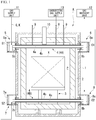
- a carburizing device A includes a chamber 1, a heat insulating container 2, a hearth 3, a plurality of heater units 4, an upper electrode portion 5, an upper ground portion 6, a lower electrode portion 7, a lower ground portion 8, carburizing gas pipes 9, an exhaust pipe 10, a gas supply unit 11, a gas recovery unit 12, a carburizing gas supply unit 13, and the like.
- the chamber 1 corresponds to a furnace body of the present disclosure.
- the gas supply unit 11 corresponds to an inert gas supply unit and an air supply unit of the present disclosure.
- the carburizing device A carburizes an object X to be treated which is accommodated in the chamber 1. That is, the carburizing device A heats the object X to be treated to a high temperature exceeding 500°C and sets an atmosphere in a carburizing chamber to a carburizing gas atmosphere. Accordingly, carbon (carbon atoms) enters a surface of the object X to be treated to form a carburized layer having a predetermined depth.
- the object X to be treated which is a processing target of the carburizing device A is a metal part whose surface hardness is increased by the carburized layer.
- the chamber 1 is a main body container (metal container) having a rectangular parallelepiped shape, and an opening/closing door (not shown) is provided on one side surface (front surface in FIG. 1 ) of the chamber 1.
- the chamber 1 is electrically grounded (earthed).
- the heat insulating container 2 is provided in the chamber 1, has a rectangular parallelepiped shape, and is formed of a heat insulating material (ceramic material) having a predetermined heat insulating performance.
- An internal space (rectangular parallelepiped space) of the heat insulating container 2 serves as a carburizing chamber P which accommodates the object X to be treated.
- the hearth 3 is a placement table on which the object X to be treated is placed, and is provided inside the heat insulating container 2 at a lower portion of the heat insulating container 2.
- the hearth 3 is formed of a ceramic material such as alumina.
- a heat insulating plate which forms one side surface of the heat insulating container 2 is provided inside the above-described opening/closing door. That is, the heat insulating container 2 includes the heat insulating plate which is provided inside the opening/closing door and can be freely opened and closed, and five heat insulating plates which are fixedly installed.
- the object X to be treated is accommodated in the carburizing chamber P by opening the opening/closing door provided on a front side of FIG. 1 .
- a right-left direction in FIG. 1 is a width direction of the carburizing device A, that is, a width direction of the chamber 1 and the heat insulating container 2
- an up-down direction in FIG. 1 is a height direction of the carburizing device A
- a direction orthogonal to the right-left direction and the up-down direction in FIG. 1 is a depth direction of the carburizing device A.
- the plurality of heater units 4 are rod-shaped members having a predetermined length and extending in a horizontal direction, and are disposed at upper and lower portions such that the object X to be treated is interposed therebetween in a vertical direction. That is, as shown in FIG. 1 , the plurality of heater units 4 are provided at the upper and lower portions in the heat insulating container 2 in a posture in which an axial direction thereof is the width direction of the carburizing device A (chamber 1 and heat insulating container 2). As shown in FIGS. 2A and 2B and FIGS. 3A and 3B , the heater units 4 are provided at a predetermined interval in the depth direction of the carburizing device A (chamber 1 and heat insulating container 2).
- each heater unit 4 is provided in the depth direction of the upper portion (upper portion of the carburizing chamber P) in the heat insulating container 2, and as shown in FIGS. 3A and 3B , eight heater units 4 are provided in the depth direction of the lower portion in the heat insulating container 2.
- the seven heater units 4 provided in the upper portion of the carburizing chamber P are upper heater units 4A.
- Each upper heater unit 4A has a first end (left end) supported by the upper electrode portion 5 and a second end (right end) supported by the upper ground portion 6.
- the eight heater units 4 provided in the lower portion of the carburizing chamber P are lower heater units 4B.
- Each lower heater unit 4B has a first end (left end) supported by the lower electrode portion 7 and a second end (right end) supported by the lower ground portion 8.
- Each heater unit 4 (upper heater unit 4A and lower heater unit 4B) includes a heater body 4a and a protective tube 4b.
- the heater body 4a has a first end located on the upper electrode portion 5 side or the lower electrode portion 7 side and connected to a power source, and a grounded second end located on the upper ground portion 6 side or the lower ground portion 8 side.
- the heater body 4a is a cylindrical electric heater (resistance heating element) which generates heat by energization from the power source to the first end, and is a ceramic heater formed of ceramic or a graphite heater formed of graphite, for example.
- the heater body 4a corresponds to a heater of the present disclosure
- the protective tube 4b corresponds to a protective member of the present disclosure.
- the protective tube 4b is a ceramic tubular member (straight tube) having an inner diameter larger than a diameter of the heater body 4a, and is provided so as to cover the heater body 4a.
- An inner surface of the protective tube 4b and a surface of the heater body 4a respectively are an annular surface and a columnar surface which are concentric and face each other at a predetermined interval.
- an inert gas G or a compressed air K for burnout flows between the inner surface of the protective tube 4b and the surface of the heater body 4a.
- the upper electrode portion 5 is a structure which mechanically supports the first ends (left ends) of the upper heater units 4A, and is provided to cover the first ends (left ends) of the seven upper heater units 4A as a whole at a left upper portion of the chamber 1, as shown in FIGS. 1 , 2A , and 2B .
- the upper electrode portion 5 includes an enclosing member 5a, seven receiving members 5b, and the like.
- the enclosing member 5a is a metal member formed in a substantially rectangular parallelepiped shape, and is provided on the left upper portion of the chamber 1 so as to enclose the first ends (left ends) of the seven upper heater units 4A as a whole.
- An inside of the enclosing member 5a, that is, a space which accommodates the first ends (left ends) of the seven upper heater units 4A is a substantially hermetically sealed space, and serves as a gas supply chamber S1 to which the inert gas G or the compressed air K for burnout is supplied from the gas supply unit 11.
- the receiving member 5b is provided corresponding to each upper heater unit 4A, and is an insulating material which receives a load of the first end (left end) of the upper heater unit 4A. As shown in FIG. 2A , the receiving member 5b is a substantially rectangular parallelepiped shaped body having a V-shaped groove formed in an upper portion of the receiving member 5b, and the first end (left end) of the upper heater unit 4A is placed on the receiving member 5b and is engaged with the V-shaped groove.
- the upper ground portion 6 is a structure which supports the second ends (right ends) of the upper heater units 4A, and is provided to cover the second ends (right ends) of the seven upper heater units 4A as a whole at a right upper portion of the chamber 1, as shown in FIG. 1 .
- the upper ground portion 6 includes an enclosing member 6a, seven receiving members 6b which are provided to corresponding to the upper heater units 4A, and the like.
- the enclosing member 6a is a metal member formed in a substantially rectangular parallelepiped shape, and is provided on the right upper portion of the chamber 1 so as to enclose the second ends (right ends) of the seven upper heater units 4A as a whole.
- An inside of the enclosing member 6a, that is, a space which accommodates the second ends (right ends) of the seven upper heater units 4A is a substantially hermetically sealed space, and serves as a gas recovery chamber C1 from which the inert gas G or the compressed air K for burnout is recovered.
- the receiving member 6b is an insulating material which receives a load of the second end (right end) of the upper heater unit 4A.
- the receiving member 6b is a substantially rectangular parallelepiped shaped body having a V-shaped groove formed in an upper portion of the receiving member 6b, and the second end (right end) of the upper heater unit 4A is placed on the receiving member 6b and is engaged with the V-shaped groove.
- the lower electrode portion 7 is a structure which supports the first ends (left ends) of the lower heater units 4B, and is provided to cover the first ends (left ends) of the eight lower heater units 4B as a whole at a left lower portion of the chamber 1, as shown in FIGS. 1 , 3A , and 3B .
- the lower electrode portion 7 includes an enclosing member 7a, eight receiving members 7b, and the like.
- the enclosing member 7a is a metal member formed in a substantially rectangular parallelepiped shape, and is provided on the left lower portion of the chamber 1 so as to enclose the first ends (left ends) of the eight lower heater units 4B as a whole.
- An inside of the enclosing member 7a, that is, a space which accommodates the first ends (left ends) of the eight lower heater units 4B is a substantially hermetically sealed space, and serves as a gas supply chamber S2 to which the inert gas G or the compressed air K for burnout is supplied from the gas supply unit 11.
- the receiving member 7b is provided corresponding to each lower heater unit 4B, and is an insulating material which receives a load of the first end (left end) of the lower heater unit 4B.
- the receiving member 5b is a substantially rectangular parallelepiped shaped body having a V-shaped groove formed in an upper portion of the receiving member 7b, and the first end (left end) of the lower heater unit 4B is placed on the receiving member 7b and is engaged with the V-shaped groove.
- the lower ground portion 8 is a structure which supports the second ends (right ends) of the lower heater units 4B, and is provided to cover the second ends (right ends) of the eight lower heater units 4B as a whole at a right lower portion of the chamber 1, as shown in FIG. 1 .
- the lower ground portion 8 includes an enclosing member 8a, eight receiving members 8b which are provided to corresponding to the lower heater units 4B, and the like.
- the enclosing member 8a is a member formed in a substantially rectangular parallelepiped shape, and is provided on the right lower portion of the chamber 1 so as to enclose the second ends (right ends) of the eight lower heater units 4B as a whole.
- An inside of the enclosing member 8a, that is, a space which accommodates the second ends (right ends) of the eight lower heater units 4B is a substantially hermetically sealed space, and serves as a gas recovery chamber C2 from which the inert gas G or the compressed air K for burnout is recovered.
- the receiving member 8b is an insulating material which receives a load of the second end (right end) of the lower heater unit 4B.
- the receiving member 8b is a substantially rectangular parallelepiped shaped body having a V-shaped groove formed in an upper portion of the receiving member 8b, and the second end (right end) of the lower heater unit 4B is placed on the receiving member 8b and is engaged with the V-shaped groove.
- the carburizing gas pipe 9 is a tubular member for introducing a carburizing gas into the carburizing chamber P.
- a front end of the carburizing gas pipe 9 opens into the carburizing chamber P, and a rear end of the carburizing gas pipe 9 communicates with the carburizing gas supply unit 13.
- the carburizing gas having a predetermined flow rate supplied from the carburizing gas supply unit 13 is discharged to the carburizing chamber P through the carburizing gas pipes 9.
- the exhaust pipe 10 is a tubular member having one end opening to the carburizing chamber P and the other end connected to a vacuum pump (not shown).
- a gas (carburizing gas, pyrolysis gas generated by pyrolysis of carburizing gas, and the like) in the carburizing chamber P is exhausted to the outside through the exhaust pipe 10 via the vacuum pump.
- the gas supply unit 11 is connected to the two gas supply chambers S1 and S2 and supplies the inert gas G or the compressed air K for burnout to the gas supply chambers S1 and S2.
- the inert gas G is a nitrogen gas (N 2 ) pressurized to a predetermined pressure equal to or higher than a normal pressure
- the compressed air K is air pressurized to a predetermined pressure equal to or higher than the normal pressure.
- the gas recovery unit 12 is connected to the two gas recovery chambers C1 and C2, and recovers the inert gas G, the compressed air K or the like in the gas recovery chambers C1 and C2.
- the carburizing gas supply unit 13 supplies the carburizing gas to the carburizing chamber P through the carburizing gas pipes 9.
- the carburizing gas is an acetylene gas (C 2 H 2 )
- the opening/closing door provided in the chamber 1 is opened, and the object X to be treated is accommodated in the carburizing chamber P and placed on the hearth 3. Then, the opening/closing door is closed, and thus, the carburizing chamber P is hermetically sealed.
- the vacuum pump By operating the vacuum pump in this state, the carburizing chamber P is set to a predetermined pressure (carburizing pressure).
- the carburizing chamber P is heated to a predetermined temperature (carburizing temperature).
- a heating power source to each heater unit 4 (upper heater unit 4A and lower heater unit 4B)
- the carburizing chamber P is heated to a predetermined temperature (carburizing temperature).
- a carburizing gas having a predetermined flow rate is continuously supplied from the carburizing gas pipes 9 to the carburizing chamber P, and a gas existing in the carburizing chamber P is exhausted from the exhaust pipe 10 by operating the vacuum pump. That is, the carburizing gas supply unit 13 and the vacuum pump are simultaneously operated to maintain the carburizing chamber P at a predetermined carburizing pressure.
- the carburizing chamber P is maintained at the carburizing pressure and the carburizing temperature for a predetermined period (carburizing period), and during this period, carbon atoms derived from the carburizing gas enter an inside of the object X to be treated from the surface of the object X to be treated. Accordingly, a carburizing layer having a predetermined depth (carburization depth) from the surface of the object X to be treated is formed on the surface of the object X to be treated. That is, in the carburizing chamber P, the carburizing gas is pyrolyzed to generate carbon atoms and a pyrolysis gas, and a portion of the carbon atoms (carbon) generated by the pyrolysis forms the carburized layer.
- the gas supply unit 11 is operated to supply the compressed inert gas G to the upper electrode portion 5 and the lower electrode portion 7, and the gas recovery unit 12 is operated to recover the inert gas G from the upper ground portion 6 and the lower ground portion 8. That is, the inert gas G always flows from the upper electrode portion 5 toward the upper ground portion 6 and from the lower electrode portion 7 toward the lower ground portion 8 through the gap between the heater body 4a and the protective tube 4b in each heater unit 4 (upper heater unit 4A and lower heater unit 4B).
- the pyrolysis gas generated by the pyrolysis of the carburizing gas and a portion of the carburizing gas are exhausted from the exhaust pipe 10 to the outside.
- the carburizing gas is acetylene (C 2 H 2 )
- hydrogen gas (H 2 ) is generated as the pyrolysis gas, and this hydrogen gas (H 2 ) is exhausted from the carburizing chamber P through the exhaust pipe 10.
- a portion of the carbon generated by the pyrolysis of the carburizing gas enters the gap between the heater body 4a and the protective tube 4b of each the heater unit 4 (upper heater unit 4A and lower heater unit 4B) and becomes soot.
- This soot (carbon) is conductive and is a material which may change an electrical resistance of the heater body 4a. That is, in a case where the carburizing device A is operated for a long time, the electrical resistance of the heater body 4a is gradually changed from an initial state due to the soot (carbon), and thus, an amount of heat generated by the heater body 4a may be gradually changed. In this case, it is difficult for the carburizing device A to heat the carburizing chamber P to a desired carburizing temperature.
- the inert gas G always flows to the gap between the heater body 4a and the protective tube 4b in each heater unit 4 (upper heater unit 4A and lower heater unit 4B) while the object X to be treated is carburized. Therefore, it is possible to suppress or prevent deposition of the soot (carbon) in the gap between the heater body 4a and the protective tube 4b. Accordingly, in the present embodiment, it is possible to suppress or prevent adhesion of the soot (carbon) to the surface of the heater body 4a.
- the inert gas G flows through the gap between the heater body 4a and the protective tube 4b during the carburizing. Therefore, it is possible to suppress or prevent the adhesion of the soot (carbon) to the heater body 4a, and thus, it is possible to improve an operating rate of the carburizing device compared to the related art.
- burnout processing is performed regularly or irregularly. That is, only the flow of the inert gas G may not sufficiently prevent the soot (carbon) from adhering to the surface of the heater body 4a.
- the carburizing device A in order to eliminate the concerns, by supplying the compressed air from the gas supply unit 11 to the upper electrode portion 5 and the lower electrode portion 7, the soot (carbon) existing in the gap between the heater body 4a and the protective tube 4b is pressure-fed to the upper ground portion 6 and the lower ground portion 8, and the compressed air and the soot (carbon) are recovered from the upper ground portion 6 and the lower ground portion 8 to the gas recovery unit 12.
- the soot (carbon) existing in the gap between the heater body 4a and the protective tube 4b is sufficiently removed, and the electrical resistance of the heater body 4a is returned to the initial state. That is, according to the present embodiment, it is possible to reliably prevent the deposition of the soot (carbon) to the heater body 4a by the burnout processing.
- the inert gas G is supplied to the upper electrode portion 5 and the lower electrode portion 7 and recovered from the upper ground portion 6 and the lower ground portion 8. Accordingly, it is possible to effectively remove the soot existing in the gap between the heater body 4a and the protective tube 4b. That is, since the heater body 4a has a predetermined electrical resistance, in terms of voltage, the upper electrode portion 5 and the lower electrode portion 7 connected to the heating power source are on the high voltage side, and the upper ground portion 6 and the lower ground portion 8 is on the low voltage side.
- the soot tends to adhere to the high voltage side rather than the low voltage side.
- the inert gas G is supplied to the high pressure side to which the soot is likely to adhere in a state where a pressure loss of the inert gas G due to passing through the gap between the heater body 4a and the protective tube 4b is not generated. Therefore, it is possible to effectively remove the soot existing in the gap between the heater body 4a and the protective tube 4b.
Landscapes
- Engineering & Computer Science (AREA)
- Chemical & Material Sciences (AREA)
- Mechanical Engineering (AREA)
- General Engineering & Computer Science (AREA)
- Chemical Kinetics & Catalysis (AREA)
- Materials Engineering (AREA)
- Metallurgy (AREA)
- Organic Chemistry (AREA)
- Solid-Phase Diffusion Into Metallic Material Surfaces (AREA)
- Furnace Details (AREA)
Abstract
Description
- The present disclosure relates to a carburizing device.
- Priority is claimed on Japanese Patent Application No.
2017-186206, filed on September 27, 2017 -
Patent Document 1 below describes burnout in a carburizing device. That is, when an object to be treated is carburized, a carbon content (that is, soot) due to a carburizing gas adheres to an inside of a carburizing device. The burnout is processing which combusts carbon (soot) adhering to the inside (particularly, a heater or the like) of the carburizing device by introducing air into the carburizing device to remove the carbon (soot). - In addition, the burnout is described in
Patent Document 2 in addition toPatent Document 1. -
- [Patent Document 1] Japanese Patent No.
5830586 - [Patent Document 2] Japanese Unexamined Patent Application, First Publication No.
2007-131936 - Since burnout is performed during carburizing of an object to be treated using a carburizing device, the burnout may be a cause of reducing an operating rate (that is, processing efficiency of the object to be treated) of the carburizing device. Therefore, an operator of the carburizing device is required to reduce a time or frequency of the burnout as much as possible. In particular, since a heater of the carburizing device has a surface temperature higher than those other parts, adhesion of carbon (soot) to the heater is more considerable than those of other parts. Therefore, the operating rate (processing efficiency of object to be treated) of the carburizing device is likely to be reduced by the adhesion of the carbon (soot) to the heater.
- The present disclosure is made in consideration of the above-described circumstances, and an object thereof is to suppress or prevent adhesion of carbon (soot) to a heater.
- According to an aspect of the present disclosure, there is provided a carburizing device including: a furnace body which accommodates an object to be treated; a plurality of heaters which are provided in the furnace body; a plurality of protective members which cover the plurality of heaters; a carburizing gas supply unit which is configured to supply a carburizing gas into the furnace body; an inert gas supply unit which is configured to supply an inert gas to a gap between the heater and the protective member; and an air supply unit which is configured to supply air for burnout to the gap between the heater and the protective member.
- In the carburizing device of the aspect, the plurality of heaters may be rod-shaped members extending in a horizontal direction in the furnace body and may be disposed such that the object to be treated is interposed therebetween in a vertical direction.
- In the carburizing device of the aspect, the plurality of heaters may be rod-shaped members extending in a vertical direction in the furnace body and are disposed such that the object to be treated is interposed therebetween in a horizontal direction.
- In the carburizing device of the aspect, the heater may be an electric heater having a first end connected to a power source and a grounded second end, and the inert gas supply unit may be configured to supply the inert gas from the first end of the heater toward the second end of the heater.
- According to the present disclosure, the inert gas is supplied to the gap between the heater and the protective member, and thus, it is possible to suppress or prevent adhesion of carbon (soot) to the heater.
-
-
FIG. 1 is a front cross-sectional view of a carburizing device according to an embodiment of the present disclosure. -
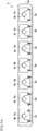
FIG. 2A is a side cross-sectional view of an upper electrode portion according to the embodiment of the present disclosure. -
FIG. 2B is a top cross-sectional view of the upper electrode portion according to the embodiment of the present disclosure. -
FIG. 3A is a side cross-sectional view of a lower electrode portion according to the embodiment of the present disclosure. -
FIG. 3B is a top cross-sectional view of the lower electrode portion according to the embodiment of the present disclosure. - Hereinafter, an embodiment of the present disclosure will be described with reference to the drawings.
- As shown in
FIG. 1 , a carburizing device A according to the present embodiment includes achamber 1, aheat insulating container 2, ahearth 3, a plurality ofheater units 4, anupper electrode portion 5, anupper ground portion 6, alower electrode portion 7, alower ground portion 8,carburizing gas pipes 9, anexhaust pipe 10, agas supply unit 11, agas recovery unit 12, a carburizinggas supply unit 13, and the like. - Among the components, the
chamber 1 corresponds to a furnace body of the present disclosure. Moreover, thegas supply unit 11 corresponds to an inert gas supply unit and an air supply unit of the present disclosure. - The carburizing device A carburizes an object X to be treated which is accommodated in the
chamber 1. That is, the carburizing device A heats the object X to be treated to a high temperature exceeding 500°C and sets an atmosphere in a carburizing chamber to a carburizing gas atmosphere. Accordingly, carbon (carbon atoms) enters a surface of the object X to be treated to form a carburized layer having a predetermined depth. In addition, the object X to be treated which is a processing target of the carburizing device A is a metal part whose surface hardness is increased by the carburized layer. - The
chamber 1 is a main body container (metal container) having a rectangular parallelepiped shape, and an opening/closing door (not shown) is provided on one side surface (front surface inFIG. 1 ) of thechamber 1. Thechamber 1 is electrically grounded (earthed). Theheat insulating container 2 is provided in thechamber 1, has a rectangular parallelepiped shape, and is formed of a heat insulating material (ceramic material) having a predetermined heat insulating performance. An internal space (rectangular parallelepiped space) of theheat insulating container 2 serves as a carburizing chamber P which accommodates the object X to be treated. Thehearth 3 is a placement table on which the object X to be treated is placed, and is provided inside theheat insulating container 2 at a lower portion of theheat insulating container 2. Thehearth 3 is formed of a ceramic material such as alumina. - A heat insulating plate which forms one side surface of the
heat insulating container 2 is provided inside the above-described opening/closing door. That is, theheat insulating container 2 includes the heat insulating plate which is provided inside the opening/closing door and can be freely opened and closed, and five heat insulating plates which are fixedly installed. In the carburizing device A, the object X to be treated is accommodated in the carburizing chamber P by opening the opening/closing door provided on a front side ofFIG. 1 . - Here, a right-left direction in
FIG. 1 is a width direction of the carburizing device A, that is, a width direction of thechamber 1 and theheat insulating container 2, an up-down direction inFIG. 1 is a height direction of the carburizing device A, and a direction orthogonal to the right-left direction and the up-down direction inFIG. 1 is a depth direction of the carburizing device A. - The plurality of
heater units 4 are rod-shaped members having a predetermined length and extending in a horizontal direction, and are disposed at upper and lower portions such that the object X to be treated is interposed therebetween in a vertical direction. That is, as shown inFIG. 1 , the plurality ofheater units 4 are provided at the upper and lower portions in theheat insulating container 2 in a posture in which an axial direction thereof is the width direction of the carburizing device A (chamber 1 and heat insulating container 2). As shown inFIGS. 2A and2B andFIGS. 3A and3B , theheater units 4 are provided at a predetermined interval in the depth direction of the carburizing device A (chamber 1 and heat insulating container 2). - In addition, as shown in
FIGS. 2A and2B , sevenheater units 4 are provided in the depth direction of the upper portion (upper portion of the carburizing chamber P) in theheat insulating container 2, and as shown inFIGS. 3A and3B , eightheater units 4 are provided in the depth direction of the lower portion in theheat insulating container 2. The sevenheater units 4 provided in the upper portion of the carburizing chamber P areupper heater units 4A. Eachupper heater unit 4A has a first end (left end) supported by theupper electrode portion 5 and a second end (right end) supported by theupper ground portion 6. The eightheater units 4 provided in the lower portion of the carburizing chamber P arelower heater units 4B. Eachlower heater unit 4B has a first end (left end) supported by thelower electrode portion 7 and a second end (right end) supported by thelower ground portion 8. - Each heater unit 4 (
upper heater unit 4A andlower heater unit 4B) includes aheater body 4a and aprotective tube 4b. Theheater body 4a has a first end located on theupper electrode portion 5 side or thelower electrode portion 7 side and connected to a power source, and a grounded second end located on theupper ground portion 6 side or thelower ground portion 8 side. Theheater body 4a is a cylindrical electric heater (resistance heating element) which generates heat by energization from the power source to the first end, and is a ceramic heater formed of ceramic or a graphite heater formed of graphite, for example. In addition, theheater body 4a corresponds to a heater of the present disclosure, and theprotective tube 4b corresponds to a protective member of the present disclosure. - The
protective tube 4b is a ceramic tubular member (straight tube) having an inner diameter larger than a diameter of theheater body 4a, and is provided so as to cover theheater body 4a. An inner surface of theprotective tube 4b and a surface of theheater body 4a respectively are an annular surface and a columnar surface which are concentric and face each other at a predetermined interval. In addition, although described later in detail, an inert gas G or a compressed air K for burnout flows between the inner surface of theprotective tube 4b and the surface of theheater body 4a. - The
upper electrode portion 5 is a structure which mechanically supports the first ends (left ends) of theupper heater units 4A, and is provided to cover the first ends (left ends) of the sevenupper heater units 4A as a whole at a left upper portion of thechamber 1, as shown inFIGS. 1 ,2A , and2B . Theupper electrode portion 5 includes an enclosingmember 5a, seven receivingmembers 5b, and the like. - The enclosing
member 5a is a metal member formed in a substantially rectangular parallelepiped shape, and is provided on the left upper portion of thechamber 1 so as to enclose the first ends (left ends) of the sevenupper heater units 4A as a whole. An inside of the enclosingmember 5a, that is, a space which accommodates the first ends (left ends) of the sevenupper heater units 4A is a substantially hermetically sealed space, and serves as a gas supply chamber S1 to which the inert gas G or the compressed air K for burnout is supplied from thegas supply unit 11. - The receiving
member 5b is provided corresponding to eachupper heater unit 4A, and is an insulating material which receives a load of the first end (left end) of theupper heater unit 4A. As shown inFIG. 2A , the receivingmember 5b is a substantially rectangular parallelepiped shaped body having a V-shaped groove formed in an upper portion of the receivingmember 5b, and the first end (left end) of theupper heater unit 4A is placed on the receivingmember 5b and is engaged with the V-shaped groove. - The
upper ground portion 6 is a structure which supports the second ends (right ends) of theupper heater units 4A, and is provided to cover the second ends (right ends) of the sevenupper heater units 4A as a whole at a right upper portion of thechamber 1, as shown inFIG. 1 . Theupper ground portion 6 includes an enclosingmember 6a, seven receivingmembers 6b which are provided to corresponding to theupper heater units 4A, and the like. - The enclosing
member 6a is a metal member formed in a substantially rectangular parallelepiped shape, and is provided on the right upper portion of thechamber 1 so as to enclose the second ends (right ends) of the sevenupper heater units 4A as a whole. An inside of the enclosingmember 6a, that is, a space which accommodates the second ends (right ends) of the sevenupper heater units 4A is a substantially hermetically sealed space, and serves as a gas recovery chamber C1 from which the inert gas G or the compressed air K for burnout is recovered. - The receiving
member 6b is an insulating material which receives a load of the second end (right end) of theupper heater unit 4A. Similarly to the above-described receivingmember 5b, the receivingmember 6b is a substantially rectangular parallelepiped shaped body having a V-shaped groove formed in an upper portion of the receivingmember 6b, and the second end (right end) of theupper heater unit 4A is placed on the receivingmember 6b and is engaged with the V-shaped groove. - The
lower electrode portion 7 is a structure which supports the first ends (left ends) of thelower heater units 4B, and is provided to cover the first ends (left ends) of the eightlower heater units 4B as a whole at a left lower portion of thechamber 1, as shown inFIGS. 1 ,3A , and3B . Thelower electrode portion 7 includes an enclosingmember 7a, eight receivingmembers 7b, and the like. - The enclosing
member 7a is a metal member formed in a substantially rectangular parallelepiped shape, and is provided on the left lower portion of thechamber 1 so as to enclose the first ends (left ends) of the eightlower heater units 4B as a whole. An inside of the enclosingmember 7a, that is, a space which accommodates the first ends (left ends) of the eightlower heater units 4B is a substantially hermetically sealed space, and serves as a gas supply chamber S2 to which the inert gas G or the compressed air K for burnout is supplied from thegas supply unit 11. - The receiving
member 7b is provided corresponding to eachlower heater unit 4B, and is an insulating material which receives a load of the first end (left end) of thelower heater unit 4B. As shown inFIG. 3A , the receivingmember 5b is a substantially rectangular parallelepiped shaped body having a V-shaped groove formed in an upper portion of the receivingmember 7b, and the first end (left end) of thelower heater unit 4B is placed on the receivingmember 7b and is engaged with the V-shaped groove. - The
lower ground portion 8 is a structure which supports the second ends (right ends) of thelower heater units 4B, and is provided to cover the second ends (right ends) of the eightlower heater units 4B as a whole at a right lower portion of thechamber 1, as shown inFIG. 1 . Thelower ground portion 8 includes an enclosingmember 8a, eight receivingmembers 8b which are provided to corresponding to thelower heater units 4B, and the like. - The enclosing
member 8a is a member formed in a substantially rectangular parallelepiped shape, and is provided on the right lower portion of thechamber 1 so as to enclose the second ends (right ends) of the eightlower heater units 4B as a whole. An inside of the enclosingmember 8a, that is, a space which accommodates the second ends (right ends) of the eightlower heater units 4B is a substantially hermetically sealed space, and serves as a gas recovery chamber C2 from which the inert gas G or the compressed air K for burnout is recovered. - The receiving
member 8b is an insulating material which receives a load of the second end (right end) of thelower heater unit 4B. Similarly to the above-described receivingmember 6b, the receivingmember 8b is a substantially rectangular parallelepiped shaped body having a V-shaped groove formed in an upper portion of the receivingmember 8b, and the second end (right end) of thelower heater unit 4B is placed on the receivingmember 8b and is engaged with the V-shaped groove. - The carburizing
gas pipe 9 is a tubular member for introducing a carburizing gas into the carburizing chamber P. A front end of the carburizinggas pipe 9 opens into the carburizing chamber P, and a rear end of the carburizinggas pipe 9 communicates with the carburizinggas supply unit 13. The carburizing gas having a predetermined flow rate supplied from the carburizinggas supply unit 13 is discharged to the carburizing chamber P through the carburizinggas pipes 9. Theexhaust pipe 10 is a tubular member having one end opening to the carburizing chamber P and the other end connected to a vacuum pump (not shown). A gas (carburizing gas, pyrolysis gas generated by pyrolysis of carburizing gas, and the like) in the carburizing chamber P is exhausted to the outside through theexhaust pipe 10 via the vacuum pump. - The
gas supply unit 11 is connected to the two gas supply chambers S1 and S2 and supplies the inert gas G or the compressed air K for burnout to the gas supply chambers S1 and S2. Moreover, for example, the inert gas G is a nitrogen gas (N2) pressurized to a predetermined pressure equal to or higher than a normal pressure, and the compressed air K is air pressurized to a predetermined pressure equal to or higher than the normal pressure. Thegas recovery unit 12 is connected to the two gas recovery chambers C1 and C2, and recovers the inert gas G, the compressed air K or the like in the gas recovery chambers C1 and C2. The carburizinggas supply unit 13 supplies the carburizing gas to the carburizing chamber P through the carburizinggas pipes 9. For example, the carburizing gas is an acetylene gas (C2H2) - Next, an operation of the carburizing device A according to this embodiment will be described in detail. When the object X to be treated is carburized using the carburizing device A, the opening/closing door provided in the
chamber 1 is opened, and the object X to be treated is accommodated in the carburizing chamber P and placed on thehearth 3. Then, the opening/closing door is closed, and thus, the carburizing chamber P is hermetically sealed. By operating the vacuum pump in this state, the carburizing chamber P is set to a predetermined pressure (carburizing pressure). - Moreover, in parallel with evacuation of the carburizing chamber P by the vacuum pump, by supplying power from a heating power source to each heater unit 4 (
upper heater unit 4A andlower heater unit 4B), the carburizing chamber P is heated to a predetermined temperature (carburizing temperature). Then, by operating the carburizinggas supply unit 13 in this pressure environment and temperature environment, a carburizing gas having a predetermined flow rate is continuously supplied from the carburizinggas pipes 9 to the carburizing chamber P, and a gas existing in the carburizing chamber P is exhausted from theexhaust pipe 10 by operating the vacuum pump. That is, the carburizinggas supply unit 13 and the vacuum pump are simultaneously operated to maintain the carburizing chamber P at a predetermined carburizing pressure. - Then, the carburizing chamber P is maintained at the carburizing pressure and the carburizing temperature for a predetermined period (carburizing period), and during this period, carbon atoms derived from the carburizing gas enter an inside of the object X to be treated from the surface of the object X to be treated. Accordingly, a carburizing layer having a predetermined depth (carburization depth) from the surface of the object X to be treated is formed on the surface of the object X to be treated. That is, in the carburizing chamber P, the carburizing gas is pyrolyzed to generate carbon atoms and a pyrolysis gas, and a portion of the carbon atoms (carbon) generated by the pyrolysis forms the carburized layer.
- In the carburizing device A, in parallel with the formation of the carburized layer, the
gas supply unit 11 is operated to supply the compressed inert gas G to theupper electrode portion 5 and thelower electrode portion 7, and thegas recovery unit 12 is operated to recover the inert gas G from theupper ground portion 6 and thelower ground portion 8. That is, the inert gas G always flows from theupper electrode portion 5 toward theupper ground portion 6 and from thelower electrode portion 7 toward thelower ground portion 8 through the gap between theheater body 4a and theprotective tube 4b in each heater unit 4 (upper heater unit 4A andlower heater unit 4B). - Meanwhile, the pyrolysis gas generated by the pyrolysis of the carburizing gas and a portion of the carburizing gas are exhausted from the
exhaust pipe 10 to the outside. For example, in a case where the carburizing gas is acetylene (C2H2), hydrogen gas (H2) is generated as the pyrolysis gas, and this hydrogen gas (H2) is exhausted from the carburizing chamber P through theexhaust pipe 10. - Here, a portion of the carbon generated by the pyrolysis of the carburizing gas enters the gap between the
heater body 4a and theprotective tube 4b of each the heater unit 4 (upper heater unit 4A andlower heater unit 4B) and becomes soot. This soot (carbon) is conductive and is a material which may change an electrical resistance of theheater body 4a. That is, in a case where the carburizing device A is operated for a long time, the electrical resistance of theheater body 4a is gradually changed from an initial state due to the soot (carbon), and thus, an amount of heat generated by theheater body 4a may be gradually changed. In this case, it is difficult for the carburizing device A to heat the carburizing chamber P to a desired carburizing temperature. - In the carburizing device A according to the present embodiment, the inert gas G always flows to the gap between the
heater body 4a and theprotective tube 4b in each heater unit 4 (upper heater unit 4A andlower heater unit 4B) while the object X to be treated is carburized. Therefore, it is possible to suppress or prevent deposition of the soot (carbon) in the gap between theheater body 4a and theprotective tube 4b. Accordingly, in the present embodiment, it is possible to suppress or prevent adhesion of the soot (carbon) to the surface of theheater body 4a. - According to the present embodiment, the inert gas G flows through the gap between the
heater body 4a and theprotective tube 4b during the carburizing. Therefore, it is possible to suppress or prevent the adhesion of the soot (carbon) to theheater body 4a, and thus, it is possible to improve an operating rate of the carburizing device compared to the related art. - In addition, in the carburizing device A, burnout processing is performed regularly or irregularly. That is, only the flow of the inert gas G may not sufficiently prevent the soot (carbon) from adhering to the surface of the
heater body 4a. In the carburizing device A, in order to eliminate the concerns, by supplying the compressed air from thegas supply unit 11 to theupper electrode portion 5 and thelower electrode portion 7, the soot (carbon) existing in the gap between theheater body 4a and theprotective tube 4b is pressure-fed to theupper ground portion 6 and thelower ground portion 8, and the compressed air and the soot (carbon) are recovered from theupper ground portion 6 and thelower ground portion 8 to thegas recovery unit 12. - According to this burnout processing, the soot (carbon) existing in the gap between the
heater body 4a and theprotective tube 4b is sufficiently removed, and the electrical resistance of theheater body 4a is returned to the initial state. That is, according to the present embodiment, it is possible to reliably prevent the deposition of the soot (carbon) to theheater body 4a by the burnout processing. - In addition, according to the present embodiment, the inert gas G is supplied to the
upper electrode portion 5 and thelower electrode portion 7 and recovered from theupper ground portion 6 and thelower ground portion 8. Accordingly, it is possible to effectively remove the soot existing in the gap between theheater body 4a and theprotective tube 4b. That is, since theheater body 4a has a predetermined electrical resistance, in terms of voltage, theupper electrode portion 5 and thelower electrode portion 7 connected to the heating power source are on the high voltage side, and theupper ground portion 6 and thelower ground portion 8 is on the low voltage side. - With respect to such a voltage distribution of the
heater body 4a, the soot tends to adhere to the high voltage side rather than the low voltage side. According to the present embodiment, the inert gas G is supplied to the high pressure side to which the soot is likely to adhere in a state where a pressure loss of the inert gas G due to passing through the gap between theheater body 4a and theprotective tube 4b is not generated. Therefore, it is possible to effectively remove the soot existing in the gap between theheater body 4a and theprotective tube 4b. - Moreover, the present disclosure is not limited to the embodiment, and for example, the following modification examples are considered.
- (1) In the embodiment, the plurality of
heater units 4 are disposed so as to extend in the horizontal direction in theheat insulating container 2 such that the object X to be treated is interposed therebetween in the vertical direction. However, the present disclosure is not limited to this. The plurality ofheater units 4 may be disposed so as to extend in the vertical direction in theheat insulating container 2 such that the object X to be treated is interposed therebetween in the horizontal direction. - (2) In the embodiment, the inert gas G is supplied to the
upper electrode portion 5 and thelower electrode portion 7 and recovered from theupper ground portion 6 and thelower ground portion 8. However, the present disclosure is not limited to this. For example, in a case where a length of the heater unit 4 (heater body 4a) is relatively short, that is, in a case where a width of the carburizing device A is relatively small, the inert gas G may be supplied to theupper ground portion 6 and thelower ground portion 8 and recovered from theupper electrode portion 5 and thelower electrode portion 7. - (3) The
hearth 3 is provided at the lower portion in theheat insulating container 2, and thus, a lower portion of the object X to be treated is less likely to be heated than an upper portion thereof. In the embodiment, in consideration of the circumstances, the number (eight) oflower heater units 4B is larger than the number (seven) ofupper heater units 4A. However, the present disclosure is not limited to this. The numbers ofupper heater units 4A and thelower heater units 4B may be the same as each other. - (4) In the embodiment, the inert gas G always flows to the gap between the
heater body 4a and theprotective tube 4b while the object X to be treated is carburized. However, the present disclosure is not limited to this. For example, the inert gas G may flow intermittently, or the inert gas G may flow only in a specific time zone of the carburizing over the predetermined carburizing period, for example, only in a latter half of the carburizing. - According to the present disclosure, it is possible to suppress or prevent adhesion of carbon (soot) to a heater.
-
- A: carburizing device
- G: inert gas
- K: compressed air
- S1, S2: gas supply chamber
- C1, C2: gas recovery chamber
- P: carburizing chamber
- X: object to be treated
- 1: chamber (furnace body)
- 2: heat insulating container
- 3: hearth
- 4: heater unit
- 4A: upper heater unit
- 4B: lower heater unit
- 4a: heater body (heater)
- 4b: protective tube (protective member)
- 5: upper electrode portion
- 5a: enclosing member
- 5b: receiving member
- 6: upper ground portion
- 6a: enclosing member
- 6b: receiving member
- 7: lower electrode portion
- 7a: enclosing member
- 7b: receiving member
- 8: lower ground portion
- 8a: enclosing member
- 8b: receiving member
- 9: carburizing gas pipe
- 10: exhaust pipe
- 11: gas supply unit
- 12: gas recovery unit
- 13: carburizing gas supply unit
Claims (4)
- A carburizing device comprising:a furnace body which accommodates an object to be treated;a plurality of heaters which are provided in the furnace body;a plurality of protective members which cover the plurality of heaters;a carburizing gas supply unit which is configured to supply a carburizing gas into the furnace body;an inert gas supply unit which is configured to supply an inert gas to a gap between the heater and the protective member; andan air supply unit which is configured to supply air for burnout to the gap between the heater and the protective member.
- The carburizing device according to claim 1,
wherein the plurality of heaters are rod-shaped members extending in a horizontal direction in the furnace body, and are disposed such that the object to be treated is interposed therebetween in a vertical direction. - The carburizing device according to claim 1,
wherein the plurality of heaters are rod-shaped members extending in a vertical direction in the furnace body, and are disposed such that the object to be treated is interposed therebetween in a horizontal direction. - The carburizing device according to any one of claims 1 to 3,wherein the heater is an electric heater having a first end connected to a power source and a grounded second end, andwherein the inert gas supply unit is configured to supply the inert gas from the first end of the heater toward the second end of the heater.
Applications Claiming Priority (2)
| Application Number | Priority Date | Filing Date | Title |
|---|---|---|---|
| JP2017186206 | 2017-09-27 | ||
| PCT/JP2018/030285 WO2019064975A1 (en) | 2017-09-27 | 2018-08-14 | Carburizing device |
Publications (3)
| Publication Number | Publication Date |
|---|---|
| EP3690077A1 true EP3690077A1 (en) | 2020-08-05 |
| EP3690077A4 EP3690077A4 (en) | 2021-03-10 |
| EP3690077B1 EP3690077B1 (en) | 2025-10-29 |
Family
ID=65903490
Family Applications (1)
| Application Number | Title | Priority Date | Filing Date |
|---|---|---|---|
| EP18861380.6A Active EP3690077B1 (en) | 2017-09-27 | 2018-08-14 | Carburizing device |
Country Status (5)
| Country | Link |
|---|---|
| EP (1) | EP3690077B1 (en) |
| JP (1) | JP6736781B2 (en) |
| CN (1) | CN111065756B (en) |
| PL (1) | PL3690077T3 (en) |
| WO (1) | WO2019064975A1 (en) |
Family Cites Families (15)
| Publication number | Priority date | Publication date | Assignee | Title |
|---|---|---|---|---|
| US4249965A (en) * | 1978-09-19 | 1981-02-10 | Midland-Ross Corporation | Method of generating carrier gas |
| JPS5830586B2 (en) | 1979-11-20 | 1983-06-30 | 義郎 中松 | outdoor signage |
| JPH02141526A (en) * | 1988-11-24 | 1990-05-30 | Ngk Insulators Ltd | Atmosphere control system |
| JPH07248193A (en) * | 1994-03-11 | 1995-09-26 | Nkk Corp | Electric resistance heating furnace |
| JP2007131936A (en) | 2005-11-14 | 2007-05-31 | Nachi Fujikoshi Corp | Vacuum carburizing furnace burnout method |
| CN101565809B (en) * | 2009-06-09 | 2011-06-01 | 石家庄金刚内燃机零部件集团有限公司 | Well type air seep carbon stove and improvement of process thereof |
| EP2871248A4 (en) * | 2012-07-04 | 2015-12-16 | Kanto Yakin Kogyo Co Ltd | Heat treatment method, heat treatment device, and heat treatment system |
| JP6285232B2 (en) * | 2014-03-24 | 2018-02-28 | 高砂工業株式会社 | Heat treatment furnace |
| WO2015162989A1 (en) * | 2014-04-23 | 2015-10-29 | 株式会社Ihi | Carburizing device |
| WO2015163155A1 (en) * | 2014-04-24 | 2015-10-29 | 株式会社Ihi | Heat treatment device |
| JP5830586B1 (en) * | 2014-07-23 | 2015-12-09 | 株式会社Ihi | Carburizing equipment |
| CN205062163U (en) * | 2015-09-29 | 2016-03-02 | 重庆盛镁镁业有限公司 | Surface treatment device of metal material |
| JP2017186206A (en) | 2016-04-07 | 2017-10-12 | 京セラ株式会社 | Ferrite sintered body and inductor |
| CN206418183U (en) * | 2016-12-19 | 2017-08-18 | 华南理工大学广州学院 | A kind of nitriding furnace heating system |
| CN209039565U (en) * | 2017-11-06 | 2019-06-28 | 株式会社Ihi | Cementing plant |
-
2018
- 2018-08-14 JP JP2019544401A patent/JP6736781B2/en active Active
- 2018-08-14 WO PCT/JP2018/030285 patent/WO2019064975A1/en not_active Ceased
- 2018-08-14 CN CN201880055317.1A patent/CN111065756B/en active Active
- 2018-08-14 PL PL18861380.6T patent/PL3690077T3/en unknown
- 2018-08-14 EP EP18861380.6A patent/EP3690077B1/en active Active
Also Published As
| Publication number | Publication date |
|---|---|
| PL3690077T3 (en) | 2026-03-09 |
| JP6736781B2 (en) | 2020-08-05 |
| WO2019064975A1 (en) | 2019-04-04 |
| CN111065756A (en) | 2020-04-24 |
| JPWO2019064975A1 (en) | 2020-04-09 |
| EP3690077A4 (en) | 2021-03-10 |
| EP3690077B1 (en) | 2025-10-29 |
| CN111065756B (en) | 2021-10-26 |
Similar Documents
| Publication | Publication Date | Title |
|---|---|---|
| JP6474785B2 (en) | Process and apparatus for thermochemically strengthening a workpiece | |
| JP5766313B2 (en) | Expansion thermal plasma device | |
| KR101802559B1 (en) | Substrate processing apparatus | |
| KR20170132129A (en) | Plasma source utilizing a macro-particle reduction coating and method of using a plasma source utilizing a macro-particle reduction coating for deposition of thin film coatings and modification of surfaces | |
| JP2001160479A5 (en) | Ceramic heater and substrate processing equipment and substrate processing method using it | |
| US20190085456A1 (en) | Batch type plasma substrate processing apparatus | |
| US11495442B2 (en) | Batch type substrate processing apparatus | |
| TW201011804A (en) | Plasma process and reactor for treating metallic pieces | |
| EP3690077B1 (en) | Carburizing device | |
| KR20110084520A (en) | Catalytic Chemical Vapor Growth Device | |
| CN209039565U (en) | Cementing plant | |
| KR20100105128A (en) | Muliti-purpose plasma heat-treatment apparatus | |
| WO2020183910A1 (en) | Heating furnace and production method for graphite | |
| US4227032A (en) | Power feed through for vacuum electric furnaces | |
| JP5268103B2 (en) | Heater unit and heat treatment device | |
| JP6383910B2 (en) | Plasma CVD apparatus and film manufacturing method | |
| CN105658841B (en) | Surface processing equipment and surface treatment method | |
| JP4919272B2 (en) | Carbon nanotube forming apparatus and carbon nanotube forming method | |
| KR101539566B1 (en) | Method and apparatus for igniting silicon rods outside a cvd-reactor | |
| KR102024137B1 (en) | Quartz heater for sputter and sputtering apparatus comprising the same | |
| JP4387330B2 (en) | Material feeder | |
| US9676010B2 (en) | Installation and process for the treatment of metallic pieces by a plasma reactor | |
| JP2012054387A (en) | Plasma processing apparatus | |
| JP2006052422A (en) | Carbon fiber film forming method, film forming apparatus, and magnetron cathode made by the film forming method | |
| JPH01136959A (en) | ion carburizing furnace |
Legal Events
| Date | Code | Title | Description |
|---|---|---|---|
| STAA | Information on the status of an ep patent application or granted ep patent |
Free format text: STATUS: THE INTERNATIONAL PUBLICATION HAS BEEN MADE |
|
| PUAI | Public reference made under article 153(3) epc to a published international application that has entered the european phase |
Free format text: ORIGINAL CODE: 0009012 |
|
| STAA | Information on the status of an ep patent application or granted ep patent |
Free format text: STATUS: REQUEST FOR EXAMINATION WAS MADE |
|
| 17P | Request for examination filed |
Effective date: 20200304 |
|
| AK | Designated contracting states |
Kind code of ref document: A1 Designated state(s): AL AT BE BG CH CY CZ DE DK EE ES FI FR GB GR HR HU IE IS IT LI LT LU LV MC MK MT NL NO PL PT RO RS SE SI SK SM TR |
|
| AX | Request for extension of the european patent |
Extension state: BA ME |
|
| DAV | Request for validation of the european patent (deleted) | ||
| DAX | Request for extension of the european patent (deleted) | ||
| A4 | Supplementary search report drawn up and despatched |
Effective date: 20210208 |
|
| RIC1 | Information provided on ipc code assigned before grant |
Ipc: F27B 5/00 20060101ALI20210202BHEP Ipc: C23C 8/20 20060101AFI20210202BHEP |
|
| STAA | Information on the status of an ep patent application or granted ep patent |
Free format text: STATUS: EXAMINATION IS IN PROGRESS |
|
| 17Q | First examination report despatched |
Effective date: 20240219 |
|
| RIN1 | Information on inventor provided before grant (corrected) |
Inventor name: NAGATA, TAKAHIRO Inventor name: SAKAMOTO, OSAMU Inventor name: MITSUZUKA, MASATOSHI Inventor name: KATSUMATA, KAZUHIKO |
|
| GRAP | Despatch of communication of intention to grant a patent |
Free format text: ORIGINAL CODE: EPIDOSNIGR1 |
|
| STAA | Information on the status of an ep patent application or granted ep patent |
Free format text: STATUS: GRANT OF PATENT IS INTENDED |
|
| RIC1 | Information provided on ipc code assigned before grant |
Ipc: F27B 5/14 20060101ALI20241204BHEP Ipc: F27B 5/06 20060101ALI20241204BHEP Ipc: C23C 8/20 20060101AFI20241204BHEP |
|
| INTG | Intention to grant announced |
Effective date: 20241217 |
|
| GRAJ | Information related to disapproval of communication of intention to grant by the applicant or resumption of examination proceedings by the epo deleted |
Free format text: ORIGINAL CODE: EPIDOSDIGR1 |
|
| STAA | Information on the status of an ep patent application or granted ep patent |
Free format text: STATUS: EXAMINATION IS IN PROGRESS |
|
| INTC | Intention to grant announced (deleted) | ||
| GRAP | Despatch of communication of intention to grant a patent |
Free format text: ORIGINAL CODE: EPIDOSNIGR1 |
|
| STAA | Information on the status of an ep patent application or granted ep patent |
Free format text: STATUS: GRANT OF PATENT IS INTENDED |
|
| INTG | Intention to grant announced |
Effective date: 20250523 |
|
| GRAS | Grant fee paid |
Free format text: ORIGINAL CODE: EPIDOSNIGR3 |
|
| GRAA | (expected) grant |
Free format text: ORIGINAL CODE: 0009210 |
|
| STAA | Information on the status of an ep patent application or granted ep patent |
Free format text: STATUS: THE PATENT HAS BEEN GRANTED |
|
| AK | Designated contracting states |
Kind code of ref document: B1 Designated state(s): AL AT BE BG CH CY CZ DE DK EE ES FI FR GB GR HR HU IE IS IT LI LT LU LV MC MK MT NL NO PL PT RO RS SE SI SK SM TR |
|
| REG | Reference to a national code |
Ref country code: CH Ref legal event code: F10 Free format text: ST27 STATUS EVENT CODE: U-0-0-F10-F00 (AS PROVIDED BY THE NATIONAL OFFICE) Effective date: 20251029 Ref country code: GB Ref legal event code: FG4D |
|
| REG | Reference to a national code |
Ref country code: IE Ref legal event code: FG4D |
|
| REG | Reference to a national code |
Ref country code: DE Ref legal event code: R096 Ref document number: 602018086793 Country of ref document: DE |
|
| REG | Reference to a national code |
Ref country code: NL Ref legal event code: MP Effective date: 20251029 |
|
| PG25 | Lapsed in a contracting state [announced via postgrant information from national office to epo] |
Ref country code: ES Free format text: LAPSE BECAUSE OF FAILURE TO SUBMIT A TRANSLATION OF THE DESCRIPTION OR TO PAY THE FEE WITHIN THE PRESCRIBED TIME-LIMIT Effective date: 20251029 |
|
| REG | Reference to a national code |
Ref country code: LT Ref legal event code: MG9D |
|
| PG25 | Lapsed in a contracting state [announced via postgrant information from national office to epo] |
Ref country code: NO Free format text: LAPSE BECAUSE OF FAILURE TO SUBMIT A TRANSLATION OF THE DESCRIPTION OR TO PAY THE FEE WITHIN THE PRESCRIBED TIME-LIMIT Effective date: 20260129 |
|
| PG25 | Lapsed in a contracting state [announced via postgrant information from national office to epo] |
Ref country code: AT Free format text: LAPSE BECAUSE OF FAILURE TO SUBMIT A TRANSLATION OF THE DESCRIPTION OR TO PAY THE FEE WITHIN THE PRESCRIBED TIME-LIMIT Effective date: 20251029 Ref country code: FI Free format text: LAPSE BECAUSE OF FAILURE TO SUBMIT A TRANSLATION OF THE DESCRIPTION OR TO PAY THE FEE WITHIN THE PRESCRIBED TIME-LIMIT Effective date: 20251029 Ref country code: HR Free format text: LAPSE BECAUSE OF FAILURE TO SUBMIT A TRANSLATION OF THE DESCRIPTION OR TO PAY THE FEE WITHIN THE PRESCRIBED TIME-LIMIT Effective date: 20251029 |
|
| REG | Reference to a national code |
Ref country code: AT Ref legal event code: MK05 Ref document number: 1851623 Country of ref document: AT Kind code of ref document: T Effective date: 20251029 |
|
| PG25 | Lapsed in a contracting state [announced via postgrant information from national office to epo] |
Ref country code: NL Free format text: LAPSE BECAUSE OF FAILURE TO SUBMIT A TRANSLATION OF THE DESCRIPTION OR TO PAY THE FEE WITHIN THE PRESCRIBED TIME-LIMIT Effective date: 20251029 |
|
| PG25 | Lapsed in a contracting state [announced via postgrant information from national office to epo] |
Ref country code: RS Free format text: LAPSE BECAUSE OF FAILURE TO SUBMIT A TRANSLATION OF THE DESCRIPTION OR TO PAY THE FEE WITHIN THE PRESCRIBED TIME-LIMIT Effective date: 20260129 |
|
| PG25 | Lapsed in a contracting state [announced via postgrant information from national office to epo] |
Ref country code: IS Free format text: LAPSE BECAUSE OF FAILURE TO SUBMIT A TRANSLATION OF THE DESCRIPTION OR TO PAY THE FEE WITHIN THE PRESCRIBED TIME-LIMIT Effective date: 20260228 |
|
| PG25 | Lapsed in a contracting state [announced via postgrant information from national office to epo] |
Ref country code: PT Free format text: LAPSE BECAUSE OF FAILURE TO SUBMIT A TRANSLATION OF THE DESCRIPTION OR TO PAY THE FEE WITHIN THE PRESCRIBED TIME-LIMIT Effective date: 20260302 |
|
| PG25 | Lapsed in a contracting state [announced via postgrant information from national office to epo] |
Ref country code: LV Free format text: LAPSE BECAUSE OF FAILURE TO SUBMIT A TRANSLATION OF THE DESCRIPTION OR TO PAY THE FEE WITHIN THE PRESCRIBED TIME-LIMIT Effective date: 20251029 |
|
| PG25 | Lapsed in a contracting state [announced via postgrant information from national office to epo] |
Ref country code: BG Free format text: LAPSE BECAUSE OF FAILURE TO SUBMIT A TRANSLATION OF THE DESCRIPTION OR TO PAY THE FEE WITHIN THE PRESCRIBED TIME-LIMIT Effective date: 20251029 |
|
| PG25 | Lapsed in a contracting state [announced via postgrant information from national office to epo] |
Ref country code: LT Free format text: LAPSE BECAUSE OF FAILURE TO SUBMIT A TRANSLATION OF THE DESCRIPTION OR TO PAY THE FEE WITHIN THE PRESCRIBED TIME-LIMIT Effective date: 20251029 |
|
| PG25 | Lapsed in a contracting state [announced via postgrant information from national office to epo] |
Ref country code: SM Free format text: LAPSE BECAUSE OF FAILURE TO SUBMIT A TRANSLATION OF THE DESCRIPTION OR TO PAY THE FEE WITHIN THE PRESCRIBED TIME-LIMIT Effective date: 20251029 |
|
| PG25 | Lapsed in a contracting state [announced via postgrant information from national office to epo] |
Ref country code: DK Free format text: LAPSE BECAUSE OF FAILURE TO SUBMIT A TRANSLATION OF THE DESCRIPTION OR TO PAY THE FEE WITHIN THE PRESCRIBED TIME-LIMIT Effective date: 20251029 |
|
| PG25 | Lapsed in a contracting state [announced via postgrant information from national office to epo] |
Ref country code: IT Free format text: LAPSE BECAUSE OF FAILURE TO SUBMIT A TRANSLATION OF THE DESCRIPTION OR TO PAY THE FEE WITHIN THE PRESCRIBED TIME-LIMIT Effective date: 20251029 |
|
| PG25 | Lapsed in a contracting state [announced via postgrant information from national office to epo] |
Ref country code: EE Free format text: LAPSE BECAUSE OF FAILURE TO SUBMIT A TRANSLATION OF THE DESCRIPTION OR TO PAY THE FEE WITHIN THE PRESCRIBED TIME-LIMIT Effective date: 20251029 |
|
| PG25 | Lapsed in a contracting state [announced via postgrant information from national office to epo] |
Ref country code: CZ Free format text: LAPSE BECAUSE OF FAILURE TO SUBMIT A TRANSLATION OF THE DESCRIPTION OR TO PAY THE FEE WITHIN THE PRESCRIBED TIME-LIMIT Effective date: 20251029 |
|
| PG25 | Lapsed in a contracting state [announced via postgrant information from national office to epo] |
Ref country code: SK Free format text: LAPSE BECAUSE OF FAILURE TO SUBMIT A TRANSLATION OF THE DESCRIPTION OR TO PAY THE FEE WITHIN THE PRESCRIBED TIME-LIMIT Effective date: 20251029 |
|
| PG25 | Lapsed in a contracting state [announced via postgrant information from national office to epo] |
Ref country code: SE Free format text: LAPSE BECAUSE OF FAILURE TO SUBMIT A TRANSLATION OF THE DESCRIPTION OR TO PAY THE FEE WITHIN THE PRESCRIBED TIME-LIMIT Effective date: 20251029 |