EP3689758B1 - Fluidtransfersystem - Google Patents
Fluidtransfersystem Download PDFInfo
- Publication number
- EP3689758B1 EP3689758B1 EP19154848.6A EP19154848A EP3689758B1 EP 3689758 B1 EP3689758 B1 EP 3689758B1 EP 19154848 A EP19154848 A EP 19154848A EP 3689758 B1 EP3689758 B1 EP 3689758B1
- Authority
- EP
- European Patent Office
- Prior art keywords
- fluid
- spacecraft
- pressure
- tank
- transfer
- Prior art date
- Legal status (The legal status is an assumption and is not a legal conclusion. Google has not performed a legal analysis and makes no representation as to the accuracy of the status listed.)
- Active
Links
Images


Classifications
-
- B—PERFORMING OPERATIONS; TRANSPORTING
- B64—AIRCRAFT; AVIATION; COSMONAUTICS
- B64D—EQUIPMENT FOR FITTING IN OR TO AIRCRAFT; FLIGHT SUITS; PARACHUTES; ARRANGEMENT OR MOUNTING OF POWER PLANTS OR PROPULSION TRANSMISSIONS IN AIRCRAFT
- B64D39/00—Refuelling during flight
-
- B—PERFORMING OPERATIONS; TRANSPORTING
- B64—AIRCRAFT; AVIATION; COSMONAUTICS
- B64G—COSMONAUTICS; VEHICLES OR EQUIPMENT THEREFOR
- B64G1/00—Cosmonautic vehicles
- B64G1/22—Parts of, or equipment specially adapted for fitting in or to, cosmonautic vehicles
- B64G1/40—Arrangements or adaptations of propulsion systems
- B64G1/402—Propellant tanks; Feeding propellants
- B64G1/4024—Propellant tanks; Feeding propellants refuelling in space
-
- B—PERFORMING OPERATIONS; TRANSPORTING
- B64—AIRCRAFT; AVIATION; COSMONAUTICS
- B64D—EQUIPMENT FOR FITTING IN OR TO AIRCRAFT; FLIGHT SUITS; PARACHUTES; ARRANGEMENT OR MOUNTING OF POWER PLANTS OR PROPULSION TRANSMISSIONS IN AIRCRAFT
- B64D39/00—Refuelling during flight
- B64D39/06—Connecting hose to aircraft; Disconnecting hose therefrom
-
- B—PERFORMING OPERATIONS; TRANSPORTING
- B64—AIRCRAFT; AVIATION; COSMONAUTICS
- B64G—COSMONAUTICS; VEHICLES OR EQUIPMENT THEREFOR
- B64G1/00—Cosmonautic vehicles
- B64G1/22—Parts of, or equipment specially adapted for fitting in or to, cosmonautic vehicles
- B64G1/64—Systems for coupling or separating cosmonautic vehicles or parts thereof, e.g. docking arrangements
Definitions
- the present invention relates generally to a fluid transfer system for a spacecraft and a method of transferring fluid from a first spacecraft to a second spacecraft.
- the concept of transferring fluid in space is known.
- the transfer of propellant in space may be carried out through the use of pressure or via a pump and fluid transfer systems can be, for example, found on the International Space Station (ISS).
- ISS International Space Station
- US 2012325972 discloses a robotic satellite refuelling tool and US7257940 discloses a device and method for pumping a fluid.
- a computer prograrr comprising instructions which, when executed by a computer, cause the computer to perform the steps of transferring a fluid from a first spacecraft to a second spacecraft
- the first spacecraft comprising: a fluid transfer system comprising: a first fluid tank configured to store a fluid to be transferred; one or more transfer feedlines configured to provide a fluidic connection between the first fluid tank and the second spacecraft; and an accumulator tank comprising: a first portion connected to a pressurant supply system; a second portion in fluidic connection with the one or more transfer feedlines; and a flexible separator arranged to separate the first portion and the second portion; the steps comprising: priming the fluid transfer system by releasing fluid from the first fluid tank into the one or more transfer feedlines and the second portion of the accumulator tank; connecting the first spacecraft to the second spacecraft; transferring fluid from the first spacecraft to the second spacecraft; adjusting the pressure of the one or more transfer feedlines by adjusting a pressure
- the step of priming the fluid transfer system comprises releasing fluid from the first fluid tank such that a pressure of the first fluid tank, a pressure of the one or more transfer feedlines, and a pressure of the accumulator tank are equal.
- the step of adjusting the pressure of the one or more transfer feedlines is performed prior to the step of connecting the first spacecraft to the second spacecraft and/or prior to the step of disconnecting the first spacecraft from the second spacecraft.
- the first fluid tank is isolated by closing a valve located between the first fluid tank and the one or more transfer feedlines prior to the step of adjusting the pressure of the one or more transfer feedlines.
- the accumulator tank is isolated by closing a valve located between the second portion of the accumulator tank and the one or more transfer feedlines prior to the step of transferring fluid from the first spacecraft to the second spacecraft.
- increasing a pressure of the second portion of the accumulator tank and the one or more transfer feedlines comprises pressurising the first portion of the accumulator tank by releasing a pressurant gas from the pressurant supply system.
- decreasing a pressure of the second portion of the accumulator tank and the one or more transfer feedlines comprises venting pressurant gas from the first portion of the accumulator tank by opening one or more valves connected to a venting port.
- the fluid transfer system further comprises a robotic arm, and wherein the one or more transfer feedlines pass through the robotic arm.
- the first portion of the accumulator tank is depressurised in order to decrease the pressure of the transfer feedlines to about 2 bar.
- the pressure required to transfer the fluid is determined by measuring the pressure in the first fluid tank, determining a pressure of a second fluid tank located on the second spacecraft and configured to receive the fluid from the first fluid tank and adjusting the pressure of the fluid transfer system to be greater than the pressure of the second fluid tank through use of a pressurant supply system.
- the computer program comprises further instructions, which when executed by the computer, cause the computer to perform the step of transferring fluid to a third spacecraft by repeating all steps of claim 1 except the priming step.
- a system for transferring a fluid from a first spacecraft to a second spacecraft comprising a fluid transfer system comprising: a pressurant supply system; a first fluid tank configured to store a fluid to be transferred, one or more transfer feedlines configured to provide fluidic connection between the first fluid tank and the second spacecraft, a connector for connecting the first spacecraft to the second spacecraft, an accumulator tank comprising: a first portion connected to the pressurant supply system, a second portion configured to be in fluidic communication with the one or more transfer feedlines, and a flexible separator arranged to separate the first portion and the second portion; wherein the pressurant supply system is arranged to supply pressurant gas to the first fluid tank for pressurising the first fluid tank and to supply pressurant gas to the first portion of the accumulator tank for pressurising the first portion of the accumulator tank.
- the accumulator tank according to the second aspect is configured such that a pressure of the second portion is adjusted by modifying a pressure of the first portion.
- the connector according to the second aspect comprises a robotic arm, and wherein the robotic arm comprises rigid piping and/or flexible piping and the one or more transfer feedlines pass through the robotic arm.
- the connector according to the second aspect comprises a dedicated docking interface.
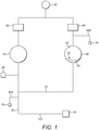
- Figure 1 illustrates a system for transferring fluid from a first spacecraft to a second spacecraft.
- the system comprises a fluid transfer system comprising a first fluid tank 10 configured to store a fluid to be transferred. Transfer feedlines 20 provide a fluidic connection between the first fluid tank 10 and the second spacecraft (not shown).
- a pressurant supply system 30 is arranged to supply pressurant gas to the first fluid tank 10 in order to pressurise the first fluid tank 10 and is also connected to an accumulator tank 40.
- the system additionally comprises a connector 50 for connecting the first spacecraft to the second spacecraft, electronic pressure regulators 60, venting ports 70, a propulsion system 80 for manoeuvring the first spacecraft, and evacuation lines 90A and 90B.
- the system also comprises a robotic arm 100, through which transfer feedlines 20 pass.
- the fluid contained within the first fluid tank 10 is a liquid.
- the first fluid tank 10 comprises propellant. Therefore, the first fluid tank 10 may be referred to as a propellant storage tank.
- propellant it may be used as the source of propellant for manoeuvring the first spacecraft in addition to storing the propellant to be transferred.
- propellants include: mixed oxides of nitrogen, such as 3% nitric oxide, monomethyl hydrazine, and hydrazine.
- the first fluid tank 10 comprises one or more test ports for on ground testing and flight pressurisation.
- each test port is of the three barrier type, in order to comply with launch site ground safety requirements.
- the first fluid tank 10 may be isolated from the rest of the system.
- the fluid contained in the first fluid tank 10 is isolated from the transfer feedlines by means of valves (not shown), such as flow controlling solenoid valves and latch valves.
- the first fluid tank 10 may be pressurised.
- the first fluid tank may be pressurised to about 10 bar.
- the transfer feedlines 20 are configured to direct the flow of fluid from the first fluid tank 10 to either the second spacecraft or to the accumulator tank 40.
- the transfer feedlines 20 comprise valves (not shown) and an orifice (not shown) downstream of the first fluid tank 10. Valves, such as solenoid valves may be used to isolate distinct parts of the fluid transfer system.
- a fill and drain valve located on the transfer feedlines 20 may also be used for ground testing of the transfer feedlines 20.
- a filter (not shown) may be incorporated in the transfer feedlines 20 upstream of any valves, in order to protect any downstream valve seats and avoid clogging any flow orifices.
- a low pressure transducer is located downstream of the first fluid tank 10 and provides accurate pressure monitoring of the fluid exiting the tank 10.
- the first spacecraft is connected to the second spacecraft through the use of a robotic arm 100.
- the transfer lines 20 are routed through the robotic arm 100.
- the first spacecraft is connected to the second spacecraft through the use of a dedicated docking interface which is configured to dock the first spacecraft with the second spacecraft and also make the fluidic connection between the two spacecraft at the same time as docking.
- the straight arm sections of the robotic arm 100 are equipped with hard piping and flexible piping is employed around the joints.
- the pressure in the transfer feedlines passing through the robotic arm can cycle between about 2 bar and 15 bar.
- the entire length of the robotic arm 100 comprises hard/rigid piping. In other embodiments, the entire length of the robotic arm 100 comprises flexible piping.
- the pressurant supply system 30 comprises a pressurant storage tank and a pressurant gas, such as helium.
- the pressurant supply system 30 is configured to pressurise the first fluid tank 10 and the accumulator tank 40.
- the pressurant supply system 30 may be equipped with a high pressure transducer (HPT) for pressure monitoring and a fill and drain valve for on ground testing and in-flight pressurant loading.
- HPT high pressure transducer
- the pressurant supply system may be isolated from the rest of the system by means of an isolation valve, such as a shaped memory alloy (SMA) valve.
- SMA shaped memory alloy
- the accumulator tank comprises a first portion 41 connected to the pressurant supply system 30, a second portion 42 configured to be in fluidic communication with the transfer feedlines 20, and a flexible separator 43 arranged to physically separate the first portion 41 and the second portion 42 such that the first portion 41 is not contaminated with propellant vapour.
- the flexible separator 43 comprises a metallic or polymeric material, such as stainless steel, aluminium, titanium, polytetrafluoroethylene (PTFE) or ethylene propylene diene monomer rubber (EPDM).
- PTFE polytetrafluoroethylene
- EPDM ethylene propylene diene monomer rubber
- the flexible separator is similar to a bellows or a diaphragm.
- the flexible separator is similar to a piston.
- the accumulator tank 40 is configured to provide a buffer volume for initial system priming.
- the accumulator tank 40 is configured to increase and decrease the pressure in the transfer feedlines 20 by pressurisation and depressurisation of the first portion 41. Altering the pressure in the transfer feedlines 20 in this way eliminates the need for purging fluid in the transfer feedlines 20 into space.
- the accumulator tank 40 is configured to ensure that any pressurant gas vented in close proximity to the second spacecraft is not contaminated with vapour from the fluid to be transferred, thereby ensuring a "clean space" approach.
- the pressure throughout the system may be regulated through the use of two electronic pressure regulators (EPRs), one for the first fluid tank 10 and one for the accumulator tank 40.
- EPRs electronic pressure regulators
- EPRs permit simple pressure regulation throughout the mission lifetime and are advantageous because the set point of the regulator can be changed as required at any stage of the mission. As a result of this, the pressure of the first fluid tank 10 can be altered to cater for thruster operation, i.e. rendezvous manoeuvres, or transferring fluid as required.
- each EPR comprises: a number of test ports for ground testing and flight pressurisation; pressure transducers for pressure sensing for operation of the electronic pressure regulator and pressure monitoring for health checks; and dual solenoid valves to provide the regulation capability, which also act to provide barriers separating high pressure and low pressure sections.
- the mission pressurant requirement is achieved by storing pressurant gas at high pressure in the pressurant storage tank.
- the high pressure may be regulated down to the operational pressure of the first fluid tank 10 and accumulator tank 40.
- the EPRs are isolated from the first fluid tank 10 and the accumulator tank 40 by means of an isolation valve, such as a shaped memory alloy isolation valve.
- This isolation valve enables on ground testing of the pressure regulation section to be carried out without the need to pressurise the tank sections.
- the fluid transfer system has two pressure regulators. Their function is to reduce the high pressure in the pressurant storage tank to the lower pressure required for the downstream components, such as the tanks, fill-drain valve connectors and the robotic arm, and supply this pressure on demand.
- the system comprises two evacuation lines 90A and 90B.
- a first evacuation line 90A is in fluidic communication with the transfer feedlines 20 and a second evacuation line 90B is in fluidic communication with the first portion 41 of the accumulator tank 40.
- the evacuation lines 90A and 90B work in combination with the venting ports 70 to provide initial evacuation of the propellant transfer feedlines to clear the lines of pressurant gas before propellant priming, and to provide a means to reduce the pressure in the first portion 41 of the accumulator tank 40, thus reducing the pressure in the second portion 42 of the accumulator tank 40 and the transfer feedlines 20.
- the propulsion system 80 comprises a chemical propulsion system designed to assist with manoeuvring the first spacecraft and with rendezvous manoeuvers.
- the chemical propulsion system is a bipropellant system which is fuelled by propellant from the first fluid tank 10.
- the propellant is supplied to the propulsion system 80 downstream of a propellant tank filter in order to protect downstream valve seats.
- the propulsion system 80 comprises dual valve thrusters.
- the propulsion system 80 comprises latch valves which act to isolate the propulsion system from the refuelling system.
- the second spacecraft is one that is in orbit and not designed to receive fluid after launch.
- an adaptor may be required in order to make the fluidic connection between the two spacecraft.
- the second spacecraft is configured to receive fluid and therefore the adaptor will not be needed.
- Certain components such as the connector between the first spacecraft and the second spacecraft, and the robotic arm, may be pressure sensitive. In particular, these components may only be operable at low pressures.
- fluid stored in the first fluid tank 10 may be at a high pressure of about 10 bar or about 15 bar.
- the relatively high pressure of the first fluid tank 10 pressurises the transfer feedlines 20 and the second portion 42 of the accumulator tank 40 to about the same pressure as the first fluid tank 10, i.e. about 10 bar or about 15 bar.
- the connector between the first spacecraft and the second spacecraft may be unable to provide a fluidic connection between the two spacecraft when pressurised to such a high degree.
- the pressure at the connector may be too high for the connector to disconnect.
- the pressure at the connector after transferring fluid may be at about 10 bar or about 15 bar; however, in order to disconnect from the second spacecraft, the pressure at the connector must be lowered to about 2 bar.
- the accumulator tank enables the pressure in the transfer feedlines to be altered without purging fluid into space.
- the increase and decrease in pressure in the transfer feedlines is modified through the pressurisation and depressurisation of the first portion 41 of the accumulator tank 40.
- pressurant gas from the first portion 41 of the accumulator tank 40 is vented through the evacuation line 90B.
- the operation is reversed. Therefore, when an increase of pressure is desired, pressurant gas is introduced into the first portion 41 of the accumulator tank 40.
- depressurisation of the first portion 41 of the accumulator tank 40 occurs while the first spacecraft is connected to the second spacecraft.
- the robotic arm may be required to be under low pressure, e.g. about 2 bar, in order to move.
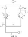
- Figure 2A represents a simplified system of that depicted in Figure 1 and illustrates the fluid transfer system at launch.
- the system comprises a first fluid tank 10 full of a fluid 11.
- the pressure of this tank is at about 10-12 bar, so that the tank 10 is able to withstand the pressures experienced during launch.
- the first fluid tank is isolated from the rest of the transfer system through use of a valve 12, such as a solenoid valve.
- the transfer feedlines 20 are preferably kept pressurised at a low pressure with a pressurant gas, such as helium. This minimises the effect of any potential failures on these sections.
- the flexible separator 43 in the accumulator tank 40 is in a contracted state and the first portion of the accumulator tank is pressurised with pressurant gas.
- the first portion of the accumulator tank is pressurised to a pressure of about 2-5 bar.
- a system health check may be performed on the fluid transfer system by means of pressure and temperature telemetry to verify that no failures have occurred during launch resulting in leakage of the system.
- the transfer feedlines Prior to priming, the transfer feedlines are evacuated of any pressurant gas by opening evacuation line 90A in fluidic connection with the transfer feedlines.
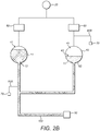
- Figure 2B shows the fluid transfer system after initial priming.
- valve 12 has been opened, allowing fluid 11 to flow from the first fluid tank 10 into the transfer feedlines 20 and the second portion 42 of the accumulator tank 40.
- the transfer feedlines 20, the second portion 42 of the accumulator tank 40, and the first portion 41 of the accumulator tank 40 are pressurised to an equal pressure.
- the pressures of the first fluid tank 10, the transfer feedlines 20, and the first 41 and second portion 42 of the accumulator tank 40 are in equilibrium. Therefore, once the valve 12 has been opened and the system has been primed, the pressure in the transfer feedlines 20 and the first portion 41 and second portion 42 of the accumulator tank 40 is about 10 bar.
- the flexible separator 43 located within the accumulator tank 40 has expanded in response to the increase of fluid and pressure in the second portion 42 of the accumulator tank 40.
- the first fluid tank 10 is isolated from the rest of the system by closing the valve 12. At this stage, a leak check may be performed.
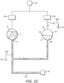
- the pressure in the transfer feedlines 20 is reduced to about 2 bar, as shown in Figure 2C . This is achieved by venting pressurant gas (see arrows) from the first portion 41 of the accumulator tank 40 and therefore decreasing the pressure in the transfer feedlines 20. Once the pressure in the transfer feedlines 20 is about 2 bar, the first spacecraft is able to remain in this state until a second spacecraft requires the transfer of fluid. This stage may be called "waiting mode".
- the first spacecraft is able to make a fluidic connection with a second spacecraft.
- the transfer feedlines 20 are re-pressurised.
- pressurant gas is introduced into the first portion 41 of the accumulator tank 40, thereby increasing the pressure in the first portion 41, thus increasing the pressure in the transfer feedlines 20.
- the accumulator tank is isolated from the rest of the transfer system through the use of a valve, such as a solenoid valve.
- the optimum pressure for transferring must be determined.
- the pressure required is dependent on the pressure, volume, and fill ratio of the tank on the second spacecraft, the volume, and fill ratio of the first fluid tank 10, and the quantity of fluid to be transferred. In some embodiments, this is achieved by determining the pressure in a tank located on the second spacecraft and configured to receive the fluid. Once this pressure is determined, the pressure in the first fluid tank and the transfer feedlines is set. This is achieved by introducing pressurant gas to the first fluid tank.
- the pressure of the fluid in the transfer feedlines 20 is pressurised to 1 bar greater than the tank on the second spacecraft. This ensures a positive pressure gradient from the first spacecraft to the second spacecraft.
- Fluid may be transferred in two modes, regulated and/or blowdown, depending on the initial delta pressure between the two spacecraft.
- the fluid will be transferred in blowdown mode and the flowrate may be controlled by the valves located directly downstream of the first fluid tank 10.
- the pressure of the tank located on the second spacecraft will be provided through spacecraft telemetry from the second spacecraft.
- the fluid will be transferred in regulated mode, with an EPR maintaining the delta pressure.
- the remainder of the fluid shall be transferred in blowdown mode and fluid transfer shall automatically stop when the first fluid tank 10 and the tank on the second spacecraft are at equilibrium.
- the pressure at which this occurs shall be predetermined by analysis.
- the initial delta pressure may be greater than necessary to initiate transfer of fluid but not sufficient to complete the transfer, the fluid shall be transferred in blowdown mode until the pressure to maintain the desired flowrate is achieved. Once this occurs, an EPR may be activated to maintain the delta pressure and when the bulk of the required quantity of fluid has been transferred, the remainder of fluid can be transferred in blowdown mode.
- Fluid may then be transferred to the second spacecraft by either blowdown or pressure regulated, as described hereinabove.
- the flowrate of fluid to be transferred is about 5 cm 3 /s.
- the fluid is transferred at a flow rate of about 5 cm 3 /s, it is easier to maintain a stable flow, thermal conditions, and allow accurate pressure monitoring.
- Fluid transfer shall cease when the tank on the second spacecraft reaches a predetermined value, indicating that the required quantity of fluid has been transferred.
- the valve may be closed.
- the pressure in the transfer feedlines is decreased by venting pressurant gas from the first portion of the accumulator tank as described above. When the pressure in the transfer feedlines has decreased to about 2 bar, the first spacecraft is able to disconnect from the second spacecraft.
- the first spacecraft now remains in "waiting mode" until connecting to a third spacecraft.
- a method for transferring fluid from a first spacecraft to a second spacecraft is illustrated in Figure 3 .
- the method comprises launching the spacecraft and priming the transfer feedlines, as set out hereinabove. Once the transfer feedlines are primed, the first spacecraft is able to dock with the second spacecraft. This represents the safest mode of operation and allows the system to be primed and checked for leaks before putting a second spacecraft at risk. In alternative embodiments, the first spacecraft docks with the second spacecraft prior to priming the transfer feedlines. In some embodiments, docking may be carried out by any known means and is carried out at a location remote from the fluid transfer system. In other embodiments, docking may be carried out via a dedicated docking interface which is capable of making a fluidic connection during the docking process.
- the docking will be located at essentially the same location as where the fluidic connection is made.
- the pressure in the transfer feedlines is reduced and a fluidic connection is made between the first spacecraft and the second spacecraft.
- the desired pressure is determined and the pressure in the fluid transfer system is adjusted accordingly, if necessary. Fluid may now be transferred from the first spacecraft to the second spacecraft. Once a predetermined amount of fluid has been transferred, the pressure in the transfer feedlines is reduced to allow the first spacecraft and the second spacecraft to disconnect.
- the above method may be implemented by one or more processors, as illustrated in Figure 4 .
- Other implementations may include a non-transitory computer readable medium, for example, such as computer-readable media that stores data for short periods of time like register memory, processor cache and Random Access Memory (RAM).
- the computer readable medium may also include non-transitory media, such as secondary or persistent long term storage, like read only memory (ROM), optical or magnetic disks, compact-disc read only memory (CD-ROM), for example.
- the computer readable media may also be any other volatile or nonvolatile storage systems.
- the computer readable medium may be considered a computer readable storage medium, a tangible storage device, or other article of manufacture, for example.
Landscapes
- Engineering & Computer Science (AREA)
- Aviation & Aerospace Engineering (AREA)
- Remote Sensing (AREA)
- Chemical & Material Sciences (AREA)
- Combustion & Propulsion (AREA)
- Filling Or Discharging Of Gas Storage Vessels (AREA)
Claims (15)
- System zum Übertragen eines Fluids von einem ersten Raumfahrzeug zu einem zweiten Raumfahrzeug, wobei das System das erste Raumfahrzeug umfasst, das ein Fluidübertragungssystem umfasst, das umfasst: ein Druckgasversorgungssystem (30);
einen ersten Fluidtank (10), der konfiguriert ist, um ein zu übertragendes Fluid zu speichern, eine oder mehrere Übertragungszuleitungen (20), die konfiguriert sind, um eine fluidische Verbindung zwischen dem ersten Fluidtank (10) und dem zweiten Raumfahrzeug bereitzustellen, einen Verbinder (50) zum Verbinden des ersten Raumfahrzeugs mit dem zweiten Raumfahrzeug, einen Speichertank (40), der umfasst:einen ersten Abschnitt (41), der mit dem Druckgasversorgungssystem (30) verbunden ist, einen zweiten Abschnitt (42), der konfiguriert ist, um in fluidischer Verbindung mit der einen oder den mehreren Übertragungszuleitungen (20) zu stehen, undein flexibles Trennstück (43), das angeordnet ist, um den ersten Abschnitt (41) und den zweiten Abschnitt (42) zu trennen; wobeidas Druckgasversorgungssystem (30) angeordnet ist, um dem ersten Fluidtank (10) Druckgas zuzuführen, um den ersten Fluidtank (10) unter Druck zu setzen, und dem ersten Abschnitt (41) des Speichertanks (40) Druckgas zuzuführen, um den ersten Abschnitt (41) des Speichertanks (40) unter Druck zu setzen. - System nach Anspruch 1, wobei der Speichertank (40) derart konfiguriert ist, dass ein Druck des zweiten Abschnitts (42) durch Modifizieren eines Drucks des ersten Abschnitts (41) eingestellt wird.
- System nach Anspruch 1 oder Anspruch 2, wobei der Verbinder (50) einen Roboterarm (100) umfasst und wobei der Roboterarm (100) starre Rohrleitungen und/oder flexible Rohrleitungen umfasst und die eine oder mehreren Übertragungszuleitungen (20) durch den Roboterarm verlaufen.
- System nach Anspruch 1 oder Anspruch 2, wobei der Verbinder (50) eine dedizierte Andock-Schnittstelle umfasst.
- Computerprogramm, umfassend Anweisungen, die, wenn sie von einem Computer ausgeführt werden, bewirken, dass der Computer, wenn er mit einem System nach Anspruch 1 verbunden ist, das System veranlasst, die Schritte auszuführen, die umfassen:Ansaugen des Fluidübertragungssystems durch Ablassen von Fluid aus dem ersten Fluidtank (10) in die eine oder mehreren Übertragungszuleitungen (20) und den zweiten Abschnitt (42) des Speichertanks (40);Verbinden des ersten Raumfahrzeugs mit dem zweiten Raumfahrzeug; Übertragen von Fluid vom ersten Raumfahrzeug zum zweiten Raumfahrzeug; Einstellen des Drucks der einen oder mehreren Übertragungszuleitungen (20) durch Einstellen eines Drucks des ersten Abschnitts (41) des Speichertanks (40); und Trennen des ersten Raumfahrzeugs vom zweiten Raumfahrzeug.
- Computerprogramm nach Anspruch 5, wobei der Schritt des Ansaugens des Fluidübertragungssystems das Ablassen von Fluid aus dem ersten Fluidtank (10) derart umfasst, dass ein Druck des ersten Fluidtanks (10), ein Druck der einen oder mehreren Übertragungsrzuleitungen (20) und ein Druck des Speichertanks (40) gleich sind.
- Computerprogramm nach Anspruch 5 oder Anspruch 6, wobei der Schritt des Einstellens des Drucks der einen oder mehreren Übertragungszuleitungen (20) vor dem Schritt des Verbindens des ersten Raumfahrzeugs mit dem zweiten Raumfahrzeug und/oder vor dem Schritt des Trennens des ersten Raumfahrzeugs vom zweiten Raumfahrzeug ausgeführt wird.
- Computerprogramm nach einem der Ansprüche 5 bis 7, wobei der erste Fluidtank (10) durch Schließen eines Ventils, das sich zwischen dem ersten Fluidtank (10) und der einen oder den mehreren Übertragungszuleitungen (20) befindet, vor dem Schritt des Einstellens des Drucks der einen oder mehreren Übertragungszuleitungen (20) isoliert wird.
- Computerprogramm nach einem der Ansprüche 5 bis 8, wobei der Speichertank (40) durch Schließen eines Ventils, das sich zwischen dem zweiten Abschnitt (42) des Speichertanks (40) und der einen oder den mehreren Übertragungszuleitungen (20) befindet, vor dem Schritt des Übertragens von Fluid vom ersten Raumfahrzeug zum zweiten Raumfahrzeug isoliert wird.
- Computerprogramm nach Anspruch 7, wobei das Erhöhen eines Drucks des zweiten Abschnitts (42) des Speichertanks (40) und der einen oder mehreren Übertragungszuleitungen (20) das Unter-Druck-Setzen des ersten Abschnitts (41) des Speichertanks (40) durch Freisetzen eines Druckgases aus dem Druckgasversorgungssystem umfasst.
- Computerprogramm nach Anspruch 7, wobei das Verringern eines Drucks des zweiten Abschnitts (42) des Speichertanks (40) und der einen oder mehreren Übertragungszuleitungen (20) das Entlüften von Druckgas aus dem ersten Abschnitt (41) des Speichertanks (40) durch Öffnen von einem oder mehreren mit einem Entlüftungsanschluss verbundenen Ventilen umfasst.
- Computerprogramm nach einem der Ansprüche 5 bis 11, wobei das Fluidübertragungssystem ferner einen Roboterarm (100) umfasst und wobei die eine oder mehreren Übertragungszuleitungen (20) durch den Roboterarm (100) verlaufen.
- Computerprogramm nach Anspruch 12, wobei vor dem Schritt des Verbindens des ersten Raumfahrzeugs mit dem zweiten Raumfahrzeug und/oder vor dem Schritt des Trennens des ersten Raumfahrzeugs von dem zweiten Raumfahrzeug der erste Abschnitt (41) des Speichertanks (40) drucklos gemacht wird, um den Druck der Übertragungszuleitungen (20) auf etwa 2 bar zu senken.
- Computerprogramm nach einem der Ansprüche 5 bis 13, wobei der zum Übertragen des Fluids erforderliche Druck durch Messen des Drucks in dem ersten Fluidtank (10), Bestimmen eines Drucks eines zweiten Fluidtanks, der sich auf dem zweiten Raumfahrzeug befindet und konfiguriert ist, um das Fluid aus dem ersten Fluidtank aufzunehmen, und Einstellen des Drucks des Fluidübertragungssystems, um höher als der Druck des zweiten Fluidtanks zu sein, durch Verwendung eines Druckgasversorgungssystems, bestimmt wird.
- Computerprogramm nach einem der Ansprüche 5 bis 14, ferner umfassend das Übertragen von Fluid an ein drittes Raumfahrzeug durch Wiederholen aller Schritte von Anspruch 1 mit Ausnahme des Ansaugschritts.
Priority Applications (5)
| Application Number | Priority Date | Filing Date | Title |
|---|---|---|---|
| ES19154848T ES2861158T3 (es) | 2019-01-31 | 2019-01-31 | Sistema de transferencia de fluidos |
| EP19154848.6A EP3689758B1 (de) | 2019-01-31 | 2019-01-31 | Fluidtransfersystem |
| PCT/EP2020/051691 WO2020156931A1 (en) | 2019-01-31 | 2020-01-23 | A fluid transfer system |
| US17/427,272 US11352151B2 (en) | 2019-01-31 | 2020-01-23 | Fluid transfer system |
| CA3125238A CA3125238C (en) | 2019-01-31 | 2020-01-23 | System and method for fluid transfer between spacecraft using a pressurant supply system |
Applications Claiming Priority (1)
| Application Number | Priority Date | Filing Date | Title |
|---|---|---|---|
| EP19154848.6A EP3689758B1 (de) | 2019-01-31 | 2019-01-31 | Fluidtransfersystem |
Publications (2)
| Publication Number | Publication Date |
|---|---|
| EP3689758A1 EP3689758A1 (de) | 2020-08-05 |
| EP3689758B1 true EP3689758B1 (de) | 2021-03-10 |
Family
ID=65276046
Family Applications (1)
| Application Number | Title | Priority Date | Filing Date |
|---|---|---|---|
| EP19154848.6A Active EP3689758B1 (de) | 2019-01-31 | 2019-01-31 | Fluidtransfersystem |
Country Status (5)
| Country | Link |
|---|---|
| US (1) | US11352151B2 (de) |
| EP (1) | EP3689758B1 (de) |
| CA (1) | CA3125238C (de) |
| ES (1) | ES2861158T3 (de) |
| WO (1) | WO2020156931A1 (de) |
Families Citing this family (9)
| Publication number | Priority date | Publication date | Assignee | Title |
|---|---|---|---|---|
| US11053027B2 (en) * | 2018-10-01 | 2021-07-06 | The Boeing Company | Space-based gas supply system |
| US11346306B1 (en) | 2019-01-03 | 2022-05-31 | Ball Aerospace & Technologies Corp. | Chemical and cold gas propellant systems and methods |
| US11498705B1 (en) | 2019-05-09 | 2022-11-15 | Ball Aerospace & Technology Corp. | On orbit fluid propellant dispensing systems and methods |
| US12012233B2 (en) | 2021-05-10 | 2024-06-18 | Ball Aerospace & Technologies Corp. | Active on orbit fluid propellant management and refueling systems and methods |
| CN113386981B (zh) * | 2021-06-07 | 2022-09-27 | 上海空间推进研究所 | 一种波纹式锥柱形隔膜贮箱 |
| CN113636113B (zh) * | 2021-08-26 | 2023-08-22 | 上海卫星工程研究所 | 多角度自拍系统 |
| US11945606B1 (en) | 2021-10-19 | 2024-04-02 | Ball Aerospace & Technologies Corp. | Electric propulsion based spacecraft propulsion systems and methods utilizing multiple propellants |
| FR3133649B1 (fr) * | 2022-03-15 | 2025-11-21 | Safran | Système et procédé de distribution de carburant |
| CN115743621A (zh) * | 2022-11-15 | 2023-03-07 | 深圳星际太空科技有限公司 | 一种多飞行器的推进剂补加系统 |
Family Cites Families (4)
| Publication number | Priority date | Publication date | Assignee | Title |
|---|---|---|---|---|
| US6527007B2 (en) * | 1998-12-16 | 2003-03-04 | Carl Cheung Tung Kong | Fluid transfer system |
| US7257940B1 (en) * | 2001-06-12 | 2007-08-21 | Knight Andrew F | Device and method for pumping a fluid |
| CA2831692C (en) * | 2007-03-09 | 2015-01-27 | Macdonald, Dettwiler And Associates Inc. | Satellite refuelling system and method |
| US8820353B2 (en) * | 2010-06-30 | 2014-09-02 | Carleton Technologies, Inc. | Interface assembly for space vehicles |
-
2019
- 2019-01-31 EP EP19154848.6A patent/EP3689758B1/de active Active
- 2019-01-31 ES ES19154848T patent/ES2861158T3/es active Active
-
2020
- 2020-01-23 CA CA3125238A patent/CA3125238C/en active Active
- 2020-01-23 US US17/427,272 patent/US11352151B2/en active Active
- 2020-01-23 WO PCT/EP2020/051691 patent/WO2020156931A1/en not_active Ceased
Non-Patent Citations (1)
| Title |
|---|
| None * |
Also Published As
| Publication number | Publication date |
|---|---|
| WO2020156931A1 (en) | 2020-08-06 |
| CA3125238A1 (en) | 2020-08-06 |
| CA3125238C (en) | 2023-04-11 |
| US11352151B2 (en) | 2022-06-07 |
| US20220089300A1 (en) | 2022-03-24 |
| EP3689758A1 (de) | 2020-08-05 |
| ES2861158T3 (es) | 2021-10-05 |
Similar Documents
| Publication | Publication Date | Title |
|---|---|---|
| US11352151B2 (en) | Fluid transfer system | |
| CA3037930C (en) | Propellant transfer system and method for resupply of fluid propellent to on-orbit spacecraft | |
| EP2086836B1 (de) | Systeme und verfahren zum betanken von raumfahrzeugen | |
| US12012233B2 (en) | Active on orbit fluid propellant management and refueling systems and methods | |
| CN114291297B (zh) | 月面发射飞行器推进系统 | |
| EP2588747B1 (de) | Schnittstellenanordnung für raumfahrzeuge | |
| EP3643622B1 (de) | Flüssigkeitstransportsystem | |
| KR102411716B1 (ko) | 위성용 다이어프램 추진제 탱크의 자동시험 장치 및 그 방법 | |
| JPH0567479B2 (de) | ||
| Trinh et al. | Propulsion System Architecture Refueling Capability Assessment for A Mars Transit Habitat Concept | |
| Trinh et al. | Transit Habitat Government-Reference Conceptual Design Reaction Control System Propulsion Concept Design Data Book | |
| Scroggins et al. | Surge Pressure Mitigation in the Global Precipitation Measurement Mission Core Propulsion System | |
| Kenny et al. | Guidelines for In-Space Cryogenic Propellant Transfer | |
| Eddleman et al. | Experimental Assessment of the Reciprocating Feed System | |
| Pitt et al. | Design, development and evolution of the Ariane 5 Attitude Control System (CSA) | |
| Ellion et al. | Development of the Surveyor Vernier propulsion system. | |
| Rogall et al. | Propellant feed system for Ariane 5 SCA | |
| Purohit et al. | Loading operations for spacecraft propulsion subsystems | |
| Di Matteo et al. | Modelling and Simulation of ATV Pressure Control Assembly Slam Start | |
| HELLWEG et al. | Low thrust liquid bipropellant propulsion systems of the French-German experimental telecommunication satellite Symphonie | |
| Cardin et al. | A Low Power Approach to Small Satellite Propulsion | |
| Schuster et al. | COLD-SAT orbital experiment configured for Atlas launch | |
| Griffiths | Polar Platform Propulsion Subsystem | |
| JP2001124602A (ja) | 宇宙航行体 |
Legal Events
| Date | Code | Title | Description |
|---|---|---|---|
| STAA | Information on the status of an ep patent application or granted ep patent |
Free format text: STATUS: EXAMINATION IS IN PROGRESS |
|
| PUAI | Public reference made under article 153(3) epc to a published international application that has entered the european phase |
Free format text: ORIGINAL CODE: 0009012 |
|
| 17P | Request for examination filed |
Effective date: 20190913 |
|
| AK | Designated contracting states |
Kind code of ref document: A1 Designated state(s): AL AT BE BG CH CY CZ DE DK EE ES FI FR GB GR HR HU IE IS IT LI LT LU LV MC MK MT NL NO PL PT RO RS SE SI SK SM TR |
|
| AX | Request for extension of the european patent |
Extension state: BA ME |
|
| GRAP | Despatch of communication of intention to grant a patent |
Free format text: ORIGINAL CODE: EPIDOSNIGR1 |
|
| STAA | Information on the status of an ep patent application or granted ep patent |
Free format text: STATUS: GRANT OF PATENT IS INTENDED |
|
| INTG | Intention to grant announced |
Effective date: 20201012 |
|
| GRAS | Grant fee paid |
Free format text: ORIGINAL CODE: EPIDOSNIGR3 |
|
| GRAA | (expected) grant |
Free format text: ORIGINAL CODE: 0009210 |
|
| STAA | Information on the status of an ep patent application or granted ep patent |
Free format text: STATUS: THE PATENT HAS BEEN GRANTED |
|
| AK | Designated contracting states |
Kind code of ref document: B1 Designated state(s): AL AT BE BG CH CY CZ DE DK EE ES FI FR GB GR HR HU IE IS IT LI LT LU LV MC MK MT NL NO PL PT RO RS SE SI SK SM TR |
|
| REG | Reference to a national code |
Ref country code: GB Ref legal event code: FG4D |
|
| REG | Reference to a national code |
Ref country code: CH Ref legal event code: EP Ref country code: AT Ref legal event code: REF Ref document number: 1369583 Country of ref document: AT Kind code of ref document: T Effective date: 20210315 |
|
| REG | Reference to a national code |
Ref country code: IE Ref legal event code: FG4D |
|
| REG | Reference to a national code |
Ref country code: DE Ref legal event code: R096 Ref document number: 602019002999 Country of ref document: DE |
|
| REG | Reference to a national code |
Ref country code: LT Ref legal event code: MG9D |
|
| PG25 | Lapsed in a contracting state [announced via postgrant information from national office to epo] |
Ref country code: BG Free format text: LAPSE BECAUSE OF FAILURE TO SUBMIT A TRANSLATION OF THE DESCRIPTION OR TO PAY THE FEE WITHIN THE PRESCRIBED TIME-LIMIT Effective date: 20210610 Ref country code: GR Free format text: LAPSE BECAUSE OF FAILURE TO SUBMIT A TRANSLATION OF THE DESCRIPTION OR TO PAY THE FEE WITHIN THE PRESCRIBED TIME-LIMIT Effective date: 20210611 Ref country code: FI Free format text: LAPSE BECAUSE OF FAILURE TO SUBMIT A TRANSLATION OF THE DESCRIPTION OR TO PAY THE FEE WITHIN THE PRESCRIBED TIME-LIMIT Effective date: 20210310 Ref country code: HR Free format text: LAPSE BECAUSE OF FAILURE TO SUBMIT A TRANSLATION OF THE DESCRIPTION OR TO PAY THE FEE WITHIN THE PRESCRIBED TIME-LIMIT Effective date: 20210310 Ref country code: NO Free format text: LAPSE BECAUSE OF FAILURE TO SUBMIT A TRANSLATION OF THE DESCRIPTION OR TO PAY THE FEE WITHIN THE PRESCRIBED TIME-LIMIT Effective date: 20210610 Ref country code: LT Free format text: LAPSE BECAUSE OF FAILURE TO SUBMIT A TRANSLATION OF THE DESCRIPTION OR TO PAY THE FEE WITHIN THE PRESCRIBED TIME-LIMIT Effective date: 20210310 |
|
| REG | Reference to a national code |
Ref country code: AT Ref legal event code: MK05 Ref document number: 1369583 Country of ref document: AT Kind code of ref document: T Effective date: 20210310 |
|
| REG | Reference to a national code |
Ref country code: NL Ref legal event code: MP Effective date: 20210310 |
|
| PG25 | Lapsed in a contracting state [announced via postgrant information from national office to epo] |
Ref country code: SE Free format text: LAPSE BECAUSE OF FAILURE TO SUBMIT A TRANSLATION OF THE DESCRIPTION OR TO PAY THE FEE WITHIN THE PRESCRIBED TIME-LIMIT Effective date: 20210310 Ref country code: RS Free format text: LAPSE BECAUSE OF FAILURE TO SUBMIT A TRANSLATION OF THE DESCRIPTION OR TO PAY THE FEE WITHIN THE PRESCRIBED TIME-LIMIT Effective date: 20210310 Ref country code: LV Free format text: LAPSE BECAUSE OF FAILURE TO SUBMIT A TRANSLATION OF THE DESCRIPTION OR TO PAY THE FEE WITHIN THE PRESCRIBED TIME-LIMIT Effective date: 20210310 |
|
| PG25 | Lapsed in a contracting state [announced via postgrant information from national office to epo] |
Ref country code: NL Free format text: LAPSE BECAUSE OF FAILURE TO SUBMIT A TRANSLATION OF THE DESCRIPTION OR TO PAY THE FEE WITHIN THE PRESCRIBED TIME-LIMIT Effective date: 20210310 |
|
| PG25 | Lapsed in a contracting state [announced via postgrant information from national office to epo] |
Ref country code: CZ Free format text: LAPSE BECAUSE OF FAILURE TO SUBMIT A TRANSLATION OF THE DESCRIPTION OR TO PAY THE FEE WITHIN THE PRESCRIBED TIME-LIMIT Effective date: 20210310 Ref country code: EE Free format text: LAPSE BECAUSE OF FAILURE TO SUBMIT A TRANSLATION OF THE DESCRIPTION OR TO PAY THE FEE WITHIN THE PRESCRIBED TIME-LIMIT Effective date: 20210310 Ref country code: AT Free format text: LAPSE BECAUSE OF FAILURE TO SUBMIT A TRANSLATION OF THE DESCRIPTION OR TO PAY THE FEE WITHIN THE PRESCRIBED TIME-LIMIT Effective date: 20210310 Ref country code: SM Free format text: LAPSE BECAUSE OF FAILURE TO SUBMIT A TRANSLATION OF THE DESCRIPTION OR TO PAY THE FEE WITHIN THE PRESCRIBED TIME-LIMIT Effective date: 20210310 |
|
| PG25 | Lapsed in a contracting state [announced via postgrant information from national office to epo] |
Ref country code: SK Free format text: LAPSE BECAUSE OF FAILURE TO SUBMIT A TRANSLATION OF THE DESCRIPTION OR TO PAY THE FEE WITHIN THE PRESCRIBED TIME-LIMIT Effective date: 20210310 Ref country code: PT Free format text: LAPSE BECAUSE OF FAILURE TO SUBMIT A TRANSLATION OF THE DESCRIPTION OR TO PAY THE FEE WITHIN THE PRESCRIBED TIME-LIMIT Effective date: 20210712 Ref country code: RO Free format text: LAPSE BECAUSE OF FAILURE TO SUBMIT A TRANSLATION OF THE DESCRIPTION OR TO PAY THE FEE WITHIN THE PRESCRIBED TIME-LIMIT Effective date: 20210310 Ref country code: PL Free format text: LAPSE BECAUSE OF FAILURE TO SUBMIT A TRANSLATION OF THE DESCRIPTION OR TO PAY THE FEE WITHIN THE PRESCRIBED TIME-LIMIT Effective date: 20210310 Ref country code: IS Free format text: LAPSE BECAUSE OF FAILURE TO SUBMIT A TRANSLATION OF THE DESCRIPTION OR TO PAY THE FEE WITHIN THE PRESCRIBED TIME-LIMIT Effective date: 20210710 |
|
| REG | Reference to a national code |
Ref country code: DE Ref legal event code: R097 Ref document number: 602019002999 Country of ref document: DE |
|
| PLBE | No opposition filed within time limit |
Free format text: ORIGINAL CODE: 0009261 |
|
| STAA | Information on the status of an ep patent application or granted ep patent |
Free format text: STATUS: NO OPPOSITION FILED WITHIN TIME LIMIT |
|
| PG25 | Lapsed in a contracting state [announced via postgrant information from national office to epo] |
Ref country code: DK Free format text: LAPSE BECAUSE OF FAILURE TO SUBMIT A TRANSLATION OF THE DESCRIPTION OR TO PAY THE FEE WITHIN THE PRESCRIBED TIME-LIMIT Effective date: 20210310 Ref country code: AL Free format text: LAPSE BECAUSE OF FAILURE TO SUBMIT A TRANSLATION OF THE DESCRIPTION OR TO PAY THE FEE WITHIN THE PRESCRIBED TIME-LIMIT Effective date: 20210310 |
|
| 26N | No opposition filed |
Effective date: 20211213 |
|
| PG25 | Lapsed in a contracting state [announced via postgrant information from national office to epo] |
Ref country code: IS Free format text: LAPSE BECAUSE OF FAILURE TO SUBMIT A TRANSLATION OF THE DESCRIPTION OR TO PAY THE FEE WITHIN THE PRESCRIBED TIME-LIMIT Effective date: 20210710 |
|
| PG25 | Lapsed in a contracting state [announced via postgrant information from national office to epo] |
Ref country code: MC Free format text: LAPSE BECAUSE OF FAILURE TO SUBMIT A TRANSLATION OF THE DESCRIPTION OR TO PAY THE FEE WITHIN THE PRESCRIBED TIME-LIMIT Effective date: 20210310 |
|
| REG | Reference to a national code |
Ref country code: CH Ref legal event code: PL |
|
| REG | Reference to a national code |
Ref country code: BE Ref legal event code: MM Effective date: 20220131 |
|
| PG25 | Lapsed in a contracting state [announced via postgrant information from national office to epo] |
Ref country code: LU Free format text: LAPSE BECAUSE OF NON-PAYMENT OF DUE FEES Effective date: 20220131 |
|
| PG25 | Lapsed in a contracting state [announced via postgrant information from national office to epo] |
Ref country code: BE Free format text: LAPSE BECAUSE OF NON-PAYMENT OF DUE FEES Effective date: 20220131 |
|
| PG25 | Lapsed in a contracting state [announced via postgrant information from national office to epo] |
Ref country code: LI Free format text: LAPSE BECAUSE OF NON-PAYMENT OF DUE FEES Effective date: 20220131 Ref country code: CH Free format text: LAPSE BECAUSE OF NON-PAYMENT OF DUE FEES Effective date: 20220131 |
|
| PGFP | Annual fee paid to national office [announced via postgrant information from national office to epo] |
Ref country code: IE Payment date: 20240119 Year of fee payment: 6 |
|
| PG25 | Lapsed in a contracting state [announced via postgrant information from national office to epo] |
Ref country code: MK Free format text: LAPSE BECAUSE OF FAILURE TO SUBMIT A TRANSLATION OF THE DESCRIPTION OR TO PAY THE FEE WITHIN THE PRESCRIBED TIME-LIMIT Effective date: 20210310 Ref country code: CY Free format text: LAPSE BECAUSE OF FAILURE TO SUBMIT A TRANSLATION OF THE DESCRIPTION OR TO PAY THE FEE WITHIN THE PRESCRIBED TIME-LIMIT Effective date: 20210310 |
|
| PG25 | Lapsed in a contracting state [announced via postgrant information from national office to epo] |
Ref country code: HU Free format text: LAPSE BECAUSE OF FAILURE TO SUBMIT A TRANSLATION OF THE DESCRIPTION OR TO PAY THE FEE WITHIN THE PRESCRIBED TIME-LIMIT; INVALID AB INITIO Effective date: 20190131 |
|
| PG25 | Lapsed in a contracting state [announced via postgrant information from national office to epo] |
Ref country code: TR Free format text: LAPSE BECAUSE OF FAILURE TO SUBMIT A TRANSLATION OF THE DESCRIPTION OR TO PAY THE FEE WITHIN THE PRESCRIBED TIME-LIMIT Effective date: 20210310 |
|
| PG25 | Lapsed in a contracting state [announced via postgrant information from national office to epo] |
Ref country code: MT Free format text: LAPSE BECAUSE OF FAILURE TO SUBMIT A TRANSLATION OF THE DESCRIPTION OR TO PAY THE FEE WITHIN THE PRESCRIBED TIME-LIMIT Effective date: 20210310 |
|
| PG25 | Lapsed in a contracting state [announced via postgrant information from national office to epo] |
Ref country code: IE Free format text: LAPSE BECAUSE OF NON-PAYMENT OF DUE FEES Effective date: 20250131 |
|
| PG25 | Lapsed in a contracting state [announced via postgrant information from national office to epo] |
Ref country code: SI Free format text: LAPSE BECAUSE OF FAILURE TO SUBMIT A TRANSLATION OF THE DESCRIPTION OR TO PAY THE FEE WITHIN THE PRESCRIBED TIME-LIMIT Effective date: 20210310 |
|
| PGFP | Annual fee paid to national office [announced via postgrant information from national office to epo] |
Ref country code: GB Payment date: 20260123 Year of fee payment: 8 |
|
| PGFP | Annual fee paid to national office [announced via postgrant information from national office to epo] |
Ref country code: ES Payment date: 20260227 Year of fee payment: 8 |
|
| PGFP | Annual fee paid to national office [announced via postgrant information from national office to epo] |
Ref country code: DE Payment date: 20260121 Year of fee payment: 8 |
|
| PGFP | Annual fee paid to national office [announced via postgrant information from national office to epo] |
Ref country code: IT Payment date: 20260123 Year of fee payment: 8 |
|
| PGFP | Annual fee paid to national office [announced via postgrant information from national office to epo] |
Ref country code: FR Payment date: 20260123 Year of fee payment: 8 |