EP3689727A1 - Leaning vehicle - Google Patents
Leaning vehicle Download PDFInfo
- Publication number
- EP3689727A1 EP3689727A1 EP18861719.5A EP18861719A EP3689727A1 EP 3689727 A1 EP3689727 A1 EP 3689727A1 EP 18861719 A EP18861719 A EP 18861719A EP 3689727 A1 EP3689727 A1 EP 3689727A1
- Authority
- EP
- European Patent Office
- Prior art keywords
- vehicle
- rider
- frame
- leaning
- wheel
- Prior art date
- Legal status (The legal status is an assumption and is not a legal conclusion. Google has not performed a legal analysis and makes no representation as to the accuracy of the status listed.)
- Granted
Links
Images



Classifications
-
- B—PERFORMING OPERATIONS; TRANSPORTING
- B62—LAND VEHICLES FOR TRAVELLING OTHERWISE THAN ON RAILS
- B62K—CYCLES; CYCLE FRAMES; CYCLE STEERING DEVICES; RIDER-OPERATED TERMINAL CONTROLS SPECIALLY ADAPTED FOR CYCLES; CYCLE AXLE SUSPENSIONS; CYCLE SIDECARS, FORECARS, OR THE LIKE
- B62K5/00—Cycles with handlebars, equipped with three or more main road wheels
- B62K5/02—Tricycles
- B62K5/05—Tricycles characterised by a single rear wheel
-
- B—PERFORMING OPERATIONS; TRANSPORTING
- B62—LAND VEHICLES FOR TRAVELLING OTHERWISE THAN ON RAILS
- B62K—CYCLES; CYCLE FRAMES; CYCLE STEERING DEVICES; RIDER-OPERATED TERMINAL CONTROLS SPECIALLY ADAPTED FOR CYCLES; CYCLE AXLE SUSPENSIONS; CYCLE SIDECARS, FORECARS, OR THE LIKE
- B62K5/00—Cycles with handlebars, equipped with three or more main road wheels
- B62K5/02—Tricycles
- B62K5/027—Motorcycles with three wheels
-
- B—PERFORMING OPERATIONS; TRANSPORTING
- B62—LAND VEHICLES FOR TRAVELLING OTHERWISE THAN ON RAILS
- B62J—CYCLE SADDLES OR SEATS; AUXILIARY DEVICES OR ACCESSORIES SPECIALLY ADAPTED TO CYCLES AND NOT OTHERWISE PROVIDED FOR, e.g. ARTICLE CARRIERS OR CYCLE PROTECTORS
- B62J1/00—Saddles or other seats for cycles; Arrangement thereof; Component parts
- B62J1/12—Box-shaped seats; Bench-type seats, e.g. dual or twin seats
-
- B—PERFORMING OPERATIONS; TRANSPORTING
- B62—LAND VEHICLES FOR TRAVELLING OTHERWISE THAN ON RAILS
- B62J—CYCLE SADDLES OR SEATS; AUXILIARY DEVICES OR ACCESSORIES SPECIALLY ADAPTED TO CYCLES AND NOT OTHERWISE PROVIDED FOR, e.g. ARTICLE CARRIERS OR CYCLE PROTECTORS
- B62J7/00—Luggage carriers
- B62J7/02—Luggage carriers characterised by the arrangement thereof on cycles
- B62J7/04—Luggage carriers characterised by the arrangement thereof on cycles arranged above or behind the rear wheel
-
- B—PERFORMING OPERATIONS; TRANSPORTING
- B62—LAND VEHICLES FOR TRAVELLING OTHERWISE THAN ON RAILS
- B62J—CYCLE SADDLES OR SEATS; AUXILIARY DEVICES OR ACCESSORIES SPECIALLY ADAPTED TO CYCLES AND NOT OTHERWISE PROVIDED FOR, e.g. ARTICLE CARRIERS OR CYCLE PROTECTORS
- B62J9/00—Containers specially adapted for cycles, e.g. panniers or saddle bags
- B62J9/10—Containers specially adapted for cycles, e.g. panniers or saddle bags integrated with the cycle
- B62J9/14—Containers specially adapted for cycles, e.g. panniers or saddle bags integrated with the cycle under the saddle
-
- B—PERFORMING OPERATIONS; TRANSPORTING
- B62—LAND VEHICLES FOR TRAVELLING OTHERWISE THAN ON RAILS
- B62J—CYCLE SADDLES OR SEATS; AUXILIARY DEVICES OR ACCESSORIES SPECIALLY ADAPTED TO CYCLES AND NOT OTHERWISE PROVIDED FOR, e.g. ARTICLE CARRIERS OR CYCLE PROTECTORS
- B62J9/00—Containers specially adapted for cycles, e.g. panniers or saddle bags
- B62J9/20—Containers specially adapted for cycles, e.g. panniers or saddle bags attached to the cycle as accessories
- B62J9/23—Containers specially adapted for cycles, e.g. panniers or saddle bags attached to the cycle as accessories above or alongside the rear wheel
-
- B—PERFORMING OPERATIONS; TRANSPORTING
- B62—LAND VEHICLES FOR TRAVELLING OTHERWISE THAN ON RAILS
- B62K—CYCLES; CYCLE FRAMES; CYCLE STEERING DEVICES; RIDER-OPERATED TERMINAL CONTROLS SPECIALLY ADAPTED FOR CYCLES; CYCLE AXLE SUSPENSIONS; CYCLE SIDECARS, FORECARS, OR THE LIKE
- B62K11/00—Motorcycles, engine-assisted cycles or motor scooters with one or two wheels
- B62K11/02—Frames
- B62K11/04—Frames characterised by the engine being between front and rear wheels
-
- B—PERFORMING OPERATIONS; TRANSPORTING
- B62—LAND VEHICLES FOR TRAVELLING OTHERWISE THAN ON RAILS
- B62K—CYCLES; CYCLE FRAMES; CYCLE STEERING DEVICES; RIDER-OPERATED TERMINAL CONTROLS SPECIALLY ADAPTED FOR CYCLES; CYCLE AXLE SUSPENSIONS; CYCLE SIDECARS, FORECARS, OR THE LIKE
- B62K5/00—Cycles with handlebars, equipped with three or more main road wheels
- B62K5/08—Cycles with handlebars, equipped with three or more main road wheels with steering devices acting on two or more wheels
-
- B—PERFORMING OPERATIONS; TRANSPORTING
- B62—LAND VEHICLES FOR TRAVELLING OTHERWISE THAN ON RAILS
- B62K—CYCLES; CYCLE FRAMES; CYCLE STEERING DEVICES; RIDER-OPERATED TERMINAL CONTROLS SPECIALLY ADAPTED FOR CYCLES; CYCLE AXLE SUSPENSIONS; CYCLE SIDECARS, FORECARS, OR THE LIKE
- B62K5/00—Cycles with handlebars, equipped with three or more main road wheels
- B62K5/10—Cycles with handlebars, equipped with three or more main road wheels with means for inwardly inclining the vehicle body on bends
-
- B—PERFORMING OPERATIONS; TRANSPORTING
- B62—LAND VEHICLES FOR TRAVELLING OTHERWISE THAN ON RAILS
- B62K—CYCLES; CYCLE FRAMES; CYCLE STEERING DEVICES; RIDER-OPERATED TERMINAL CONTROLS SPECIALLY ADAPTED FOR CYCLES; CYCLE AXLE SUSPENSIONS; CYCLE SIDECARS, FORECARS, OR THE LIKE
- B62K2202/00—Motorised scooters
Definitions
- the present teaching relates to a leaning vehicle provided with a right front wheel, a left front wheel and a rear wheel.
- the three-wheeled vehicles are each provided with a handlebar, a vehicle body frame, a left front wheel, a right front wheel, and a rear wheel.
- a rider operates the handlebar to rotate the left front and right front wheels in a counterclockwise direction when the three-wheeled vehicle is viewed from above. Further, the rider leans the vehicle body frame in a three-wheeled-vehicle leftward direction. This causes the three-wheeled vehicle to turn to the left.
- the rider operates the handlebar to rotate the left front and right front wheels in a clockwise direction when the three-wheeled vehicle is viewed from above. Further, the rider leans the vehicle body frame in a three-wheeled-vehicle rightward direction. This causes the three-wheeled vehicle to turn to the right.
- Patent Literature 1 and Patent Literature 2 When the three-wheeled vehicles described in Patent Literature 1 and Patent Literature 2 are to be used on business, on commuting, or other purposes, there is an increasing demand for carrying a load.
- an object of the present teaching is to increase a load capacity for a rear mounted load on a leaning vehicle while preventing the leaning vehicle from increasing in size, the leaning vehicle including a left front wheel, a right front wheel, a rear wheel, and a link mechanism, the link mechanism causing an axle of the left front wheel to be positioned further upward in a vehicle-body-frame upward direction than an axle of the right front wheel to lean a vehicle body frame in a leaning-vehicle leftward direction and causing the axle of the right front wheel to be positioned further upward in a vehicle-main-body upward direction than the axle of the left front wheel to lean a vehicle main body in a leaning-vehicle rightward direction.
- the rear mounted load refers to a load carried near and above the rear wheel.
- the present inventors For the leaning vehicle provided with a left front wheel, a right front wheel, a rear wheel, and a link mechanism, the present inventors have studied to increase a carrying section provided behind a passenger seat in a leaning-vehicle backward direction for improving user convenience.
- simply increasing the carrying section leads to a backward extension of a rear portion of the leaning vehicle or widening of the rear portion of the leaning vehicle in a left-right direction. As a result, the size of the leaning vehicle is increased.
- the present inventors have conducted a study introducing a different technical concept from those that have been proposed, which intend to improve and increase the carrying section of the leaning vehicle. Specifically, the present inventors have conducted a study introducing a technical concept to newly construct a layout of the left front wheel, the right front wheel, the rear wheel, the link mechanism, the seat, and the carrying section primarily for increasing the carrying section.
- the present inventors have first examined a weight distribution of the leaning vehicle. As a result, in the leaning vehicle provided with a left front wheel, a right front wheel, and a rear wheel, it has been found that a total percentage of the left and right front wheels in the weight distribution is larger than a percentage of a front wheel in a weight distribution of a leaning vehicle provided with one front wheel and one rear wheel. Accordingly, the present inventors have studied how a load is to be carried in a favorable manner on the leaning vehicle that has a large total percentage of the left and right front wheels in the weight distribution.
- the total percentage of the left and right front wheels in the weight distribution is larger, as described above.
- the percentage of the rear wheel in the weight distribution is smaller in the leaning vehicle provided with a left front wheel, a right front wheel, and a rear wheel.
- the present inventors have realized that the percentage of the rear wheel in the weight distribution may be increased by carrying a load near and above the rear wheel (hereinafter referred to as "rear mounted load").
- the leaning vehicle is either in a state in which the vehicle is carrying a rear mounted load (carrying state) or in a state in which the vehicle is not carrying a rear mounted load (non-carrying state).
- front weight distribution the percentage of the left and right front wheels in the weight distribution
- rear weight distribution percentage of the rear wheel in the weight distribution
- it is desirable that the rear mounted load is carried at a position where no large change occurs in the front weight distribution nor the rear weight distribution between the carrying state and the non-carrying state. Accordingly, the present inventors have studied a position where the rear mounted load is to be carried.
- the rear mounted load is carried near and above the rear wheel. Because of this, a weight applied to the rear wheel varies between the carrying state and the non-carrying state.
- the present inventors considered that a large change in the front weight distribution and the rear weight distribution can be suppressed by reducing a rate of variation of the weight applied to the rear wheel between the carrying state and the non-carrying state.
- the present inventors considered that the seat may be positioned in the leaning vehicle such that a larger part of the weight of a rider is applied to the rear wheel.
- a case in which a rider weighing 60kg sits on the seat of the leaning vehicle will be explained as an example.
- a leaning vehicle in which a weight of 20kg is applied to the left and right front wheels and a weight of 40kg is applied to the rear wheel.
- a weight of 5kg is applied to the left and right front wheels and a weight of 55kg is applied to the rear wheel.
- the weight applied to the rear wheel increases 50%.
- the weight applied to the rear wheel increases 36%.
- the present inventors have considered that the seat for a rider to sit may be positioned near the rear wheel in order to suppress a large change in the front weight distribution and the rear weight distribution between the carrying state and the non-carrying state.
- the present inventors For the leaning vehicle with a large change in the front weight distribution and the rear weight distribution being suppressed between the carrying state and the non-carrying state as described above, the present inventors have studied how a larger amount of rear mounted load can be carried without increasing the size of the leaning vehicle. Then, the present inventors have studied modes of use of leaning vehicles for business and commuting uses. The present inventors have realized that, in most cases, a leaning vehicle for business and commuting uses is ridden by only the rider without a passenger. Accordingly, the present inventors have conceived to arrange a rider-only single seat and a carrying section for rear mounted load behind the rider-only single seat.
- the present teaching adopts the following configuration in order to solve the above problem.
- the center of gravity of the rider sitting on the rider-only single seat is located near the rear wheel axle.
- the rider-only single seat when the engine is seen from the vehicle-body-frame leftward or rightward direction, the rider-only single seat is disposed above the central axis of rotation of the crankshaft of a power unit, as the engine, in the vehicle-body-frame upward direction. Accordingly, the distance between the rider-only single seat and the power unit is short in the vehicle-body-frame front-back direction.
- the power unit is disposed near the rear wheel. As a result, the distance between the rider-only single seat and the rear wheel axle is short in the vehicle-body-frame front-back direction. Accordingly, in the leaning vehicle of (5), the center of gravity of the rider sitting on the rider-only single seat is located near the rear wheel axle.
- a load capacity for a rear mounted load on a leaning vehicle can be increased while preventing the leaning vehicle from increasing in size, the leaning vehicle including a left front wheel, a right front wheel, a rear wheel, and a link mechanism, the link mechanism causing an axle of the left front wheel to be positioned further upward in a vehicle-body-frame upward direction than an axle of the right front wheel to lean a vehicle body frame in a leaning-vehicle leftward direction and causing the axle of the right front wheel to be positioned further upward in a vehicle-main-body upward direction than the axle of the left front wheel to lean a vehicle main body in a leaning-vehicle rightward direction.
- FIG. 1 is a view of the leaning vehicle 1 as seen from the vehicle-body-frame (21) leftward direction with the vehicle body frame 21 being upright.
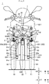
- FIG. 2 is a view of the front portion of the leaning vehicle 1 as seen from the vehicle-body-frame (21) frontward direction with the vehicle body frame 21 being upright.
- FIG. 2 illustrates a state in which the vehicle body 22 is transparent.
- the leaning-vehicle (1) frontward direction is referred to as a frontward direction "F".
- the leaning-vehicle (1) backward direction is referred to as a backward direction "B".
- the leaning-vehicle (1) leftward direction is referred to as a leftward direction "L”.
- the leaning-vehicle (1) rightward direction is referred to as a rightward direction "R”.
- the leaning-vehicle (1) upward direction is referred to as an upward direction "U”.
- the leaning-vehicle (1) downward direction is referred to as a downward direction "D”.
- the leaning-vehicle (1) front-back direction is referred to as a front-back direction "FB”.
- the leaning-vehicle (1) left-right direction is referred to as a left-right direction "LR".
- the leaning-vehicle (1) up-down direction is referred to as an up-down direction "UD”.
- the leaning-vehicle (1) frontward direction refers to the traveling direction of the leaning vehicle 1.
- the leaning-vehicle (1) backward direction refers to a direction opposite to the traveling direction of the leaning vehicle 1.
- the leaning-vehicle (1) leftward direction refers to the leftward direction with respect to a rider who straddles the leaning vehicle 1.
- the leaning-vehicle (1) rightward direction refers to the rightward direction with respect to the rider who straddles the leaning vehicle 1.
- the leaning-vehicle (1) upward direction refers to the upward direction with respect to a rider who straddles the leaning vehicle 1.
- the leaning-vehicle (1) downward direction refers to the downward direction with respect to a rider who straddles the leaning vehicle 1.
- the vehicle body frame 21 can lean in the leftward direction L or the rightward direction R.
- the vehicle-body-frame (21) up-down and left-right directions do not coincide with the leaning-vehicle (1) up-down direction UD and the leaning-vehicle (1) left-right direction LR, respectively.
- the vehicle-body-frame (21) up-down and left-right directions in an upright state coincide with the leaning-vehicle (1) up-down direction UD and the leaning-vehicle (1) left-right direction LR, respectively.
- the vehicle-body-frame (21) frontward direction is referred to as a frontward direction "f".
- the vehicle-body-frame (21) backward direction is referred to as a backward direction "b".
- the vehicle-body-frame (21) leftward direction is referred to as a leftward direction "l”.
- the vehicle-body-frame (21) rightward direction is referred to as a rightward direction "r”.
- the vehicle-body-frame (21) upward direction is referred to as an upward direction "u”.
- the vehicle-body-frame (21) downward direction is referred to as a downward direction "d”.
- the vehicle-body-frame (21) front-back direction is referred to as a front-back direction "fb”.
- the vehicle-body-frame (21) left-right direction is referred to as a left-right direction "lr”.
- the vehicle-body-frame (21) up-down direction is referred to as an up-down direction "ud”.
- an upper end of a component denotes an end of the top portion of the component.
- a lower end of a component denotes an end of the bottom portion of the component.
- a front end of a component denotes an end of the front of the component.
- the rear end of a component denotes an end of the rear of the component.
- the left end of a component denotes an end of the left of the component.
- the right end of a component denotes an end of the right of the component.
- the upper end portion of a component denotes the upper end and its vicinity of the component.
- the lower end portion of a component denotes the lower end and its vicinity of the component.
- the front end portion of a component denotes the front end and its vicinity of the component.
- the rear end portion of a component denotes the rear end and its vicinity of the component.
- the left end portion of a component denotes the left end and its vicinity of the component.
- the right end portion of a component denotes the right end and its vicinity of the component.
- the component denotes the leaning vehicle 1 and a member constituting the leaning vehicle 1.
- An axis or a member extending in the front-back direction does not necessarily refer to only an axis or a member that is in parallel with the front-back direction.
- An axis or a member extending in the front-back direction refers to an axis or a member that is inclined within a range of ⁇ 45° with respect to the front-back direction.
- an axis or a member extending in the up-down direction refers to an axis or a member that is inclined within a range of ⁇ 45° with respect to the up-down direction.
- An axis or a member extending in the left-right direction refers to an axis or a member that is inclined within a range of ⁇ 45° with respect to the left-right direction.
- an "upright" state of the vehicle body frame 21 means a state in which the front wheels are not steered nor leaning while no rider is riding on nor no fuel is stored in the leaning vehicle 1.
- a phrase "a first member is supported by a second member” includes both a case in which the first member is attached to (i.e. fixed to) the second member unmovably with respect to the second member and a case in which the first member is attached to the second member movably with respect to the second member. Further, a phrase "a first member is supported by a second member” includes both a case in which the first member is directly attached to the second member and a case in which the first member is attached to the second member with an intervening third member.
- the leaning vehicle 1 includes a vehicle main body section 2, a left front wheel 31 (see FIG. 2 ), a right front wheel 32 (see FIG. 2 ), a rear wheel 4, a link mechanism 5, and a steering mechanism 7.
- the vehicle main body section 2 includes the vehicle body frame 21, the vehicle body cover 22, the rider-only single seat 24, and the power unit 25.
- the vehicle body frame 21 leans in the leftward direction L in turning left.
- the vehicle body frame 21 leans in the rightward direction R in turning right.
- the vehicle body frame 21 includes a headpipe 211, a downframe 212, an underframe 214, and a rearframe 215.
- FIG. 1 portions of the vehicle body frame 21 hidden by the vehicle body cover 22 are illustrated in dashed lines.
- the vehicle body frame 21 supports the rider-only single seat 24, the power unit 25, and the like.
- the headpipe 211 is disposed in the front portion of the leaning vehicle 1.
- the front portion of the leaning vehicle 1 refers to a portion located further frontward than the front end of the rider-only single seat 24 in the frontward direction f in the leaning vehicle 1.
- the rear portion of the leaning vehicle 1 refers to a portion located further backward than the front end of the rider-only single seat 24 in the backward direction b in the leaning vehicle 1.
- the headpipe 211 is inclined with respect to the up-down direction ud such that the upper end portion of the headpipe 211 is located further backward than the lower end portion of the headpipe 211 in the backward direction b.
- the steering mechanism 7 and the link mechanism 5 are disposed around the headpipe 211.
- a steering shaft 60 of the steering mechanism 7 is rotatably inserted in the headpipe 211.
- the link mechanism 5 is supported by the headpipe 211.
- the downframe 212 is disposed further backward than the headpipe 211 in the backward direction b.
- the downframe 212 has a cylindrical shape extending in the up-down direction ud.
- the upper end portion of the downframe 212 is located behind the lower end portion of the headpipe 211 in the backward direction b. Further, the upper end portion of the downframe 212 is fixed to the lower end portion of the headpipe 211 by an unillustrated connection.
- the underframe 214 extends from the lower end portion of the downframe 212 in the backward direction b and the upward direction u.
- the rearframe 215 extends from the rear end of the underframe 214 in the backward direction b and the upward direction u.
- the vehicle body frame 21 is covered with the vehicle body cover 22.
- the vehicle body cover 22 includes a front cover 221, a front fender pair 223 of right and left front fenders, and a leg shield 225.
- the front cover 221 is located in front of the rider-only single seat 24 in the frontward direction f.
- the front cover 221 covers at least part of the steering mechanism 7 and at least part of the link mechanism 5.
- the power unit 25 includes the engine, a transmission, and the like.
- the power unit 25 generates a driving force to rotate the rear wheel 4.
- the engine has a crankshaft.
- the central axis of rotation of the crankshaft is a central axis Ax extending in the left-right direction lr.
- the left front wheel 31 is disposed further leftward in the leftward direction 1 than the center C0 of the vehicle body frame 21 in the left-right direction lr.
- the left front wheel 31 is rotatable around the left-front-wheel axle 314.
- the right front wheel 32 is disposed further rightward in the rightward direction r than the center C0 of the vehicle body frame 21 in the left-right direction lr.
- the right front wheel 32 is rotatable around the right-front-wheel axle 324.
- the left front wheel 31 and the right front wheel 32 are symmetrically disposed with respect to the center C0.
- the front fender pair 223 includes a left front fender 227 and a right front fender 228.
- the left front fender 227 is disposed above the left front wheel 31 in the upward direction u.
- the right front fender 228 is disposed above the right front wheel 32 in the upward direction u.
- the rear wheel 4 is disposed further backward than the left front wheel 31 and the right front wheel 32 in the backward direction b.
- the rear wheel 4 is rotatable around the rear wheel axle 414.
- the rear wheel 4 is rotated by a driving force generated by the power unit 25.
- the rider-only single seat 24 is disposed between the left-front-wheel axle 314 or the right-front-wheel axle 324 and the rear wheel axle 414 in the front-back direction fb. Further, when the leaning vehicle 1 is seen from the leftward direction 1 or the rightward direction r, the rider-only single seat 24 is disposed above the central axis Ax in the upward direction u. The rider-only single seat 24 is supported by the vehicle body frame 21. The rider-only single seat 24 is a seat only for a rider 500 who steers the steering mechanism 7 described later to sit. Accordingly, the rider-only single seat 24 is designed to have a short length in the front-back direction fb.
- a length L11 of the rider-only single seat 24 in the front-back direction fb is shorter than a length L12 from a wheelbase center WBC to the rear wheel axle 414 in the front-back direction fb.
- the wheelbase center WBC refers to a central point between the left-front-wheel axle 314 or the right-front-wheel axle 324 and the rear wheel axle 414 in the front-back direction fb.
- the rider-only single seat 24 includes a seating surface 24a and a back rest 24b.
- the seating surface 24a is an area that pushes the hip of the rider 500 in the upward direction u. Accordingly, the seating surface 24a is a plane facing the upward direction u. However, the seating surface 24a may not be completely flat but may be substantially flat. Accordingly, the seating surface 24a may have a slightly curved shape or a slightly textured shape for slip resistance. However, the distance between the upper end of the seating surface 24a and the lower end of the seating surface 24a in the up-down direction ud is equal to or less than 5 cm. Further, the normal of the seating surface 24a may not coincide with the upward direction u.
- the normal of the seating surface 24a refers to a normal of a plane that includes the front end of the seating surface 24a (hereinafter referred to as "seating surface front end SFF") and the rear end of the seating surface 24a (hereinafter referred to as “seating surface rear end SFB”) and that is in parallel with the left-right direction lr.
- the normal of the seating surface 24a may be inclined with respect to the upward direction u to the extent that the rider 500 can sit. Specifically, the normal of the seating surface 24a may for example be inclined forward up to 10° with respect to the upward direction u.
- an arcuate surface S1 is arranged in front of the seating surface 24a in the frontward direction f.
- the seating surface front end SFF corresponds to the rear end of the arcuate surface S1.
- an arcuate surface S2 is arranged behind the seating surface 24a in the backward direction b.
- the seating surface rear end SFB corresponds to the front end of the arcuate surface S2.
- the back rest 24b is a portion located further backward than the front end of arcuate surface S2 in the backward direction b in the rider-only single seat 24. The back rest 24b supports the rider 500 in his/her hip from the backward direction b.
- hip point HP A point where a hip joint of the rider 500 is located when the rider 500 is sitting on the rider-only single seat 24 is referred to as a hip point HP.
- the hip point HP When seen from the leftward direction 1, the hip point HP is located 20 cm behind the front end of seating surface 24a of the rider-only single seat 24 in the backward direction b.
- the seating surface 24a is designed to have a short length in the front-back direction fb.
- the length of the seating surface 24a in the front-back direction fb is in a range of 20 cm or more and 45 cm or less, for example.
- the rider-only single seat 24 includes only one seating surface 24a without including a plurality of seating surfaces.
- the reference to a plurality of seating surfaces means that two or more adjacent planes in the front-back direction fb are disposed at different levels in the up-down direction ud.
- the length of one of the two or more planes in the front-back direction fb is equal to or larger than 10 cm.
- the length of the upper surface of the back rest 24b in the front-back direction is shorter than 10 cm. As such, the upper surface of the back rest 24b is not included in the two or more planes.
- the rider-only single seat 24 does not allow a passenger to sit. Further, the leaning vehicle 1 is provided with no other seats than the rider-only single seat 24. Accordingly, the seating capacity of the leaning vehicle 1 is one person. For example, the seating capacity of the leaning vehicle 1 can be confirmed in an instruction manual or an automobile inspection certificate.
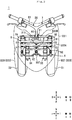
- FIG. 3 is a view of the front portion of the leaning vehicle 1 as seen from an upward direction u with the vehicle body frame 21 being upright.
- FIG. 3 illustrates a state in which the vehicle body cover 22 is transparent.
- the steering mechanism 7 steers the left front wheel 31 and the right front wheel 32. As illustrated in FIGS. 2 and 3 , the steering mechanism 7 includes a steering force transmitting mechanism 6, a left shock absorber 33, and a right shock absorber 34.
- the left shock absorber 33 movably supports the left front wheel 31 with respect to the vehicle body frame 21 in the up-down direction ud.
- the left shock absorber 33 includes a left lower portion 33a, a left upper portion 33b, and a left support portion 33c.
- the left lower portion 33a extends in the up-down direction ud.
- the left support portion 33c is disposed in the lower end portion of the left lower portion 33a.
- the left support portion 33c rotatably supports the left front wheel 31.
- the left front wheel 31 is rotatable around the left-front-wheel axle 314 as the central axis.
- the left-front-wheel axle 314 extends from the left support portion 33c in the leftward direction 1.
- the left upper portion 33b extends in the up-down direction ud.
- the left upper portion 33b is disposed above the left lower portion 33a in the upward direction u with the vicinity of the lower end of the left upper portion 33b being inserted in the left lower portion 33a.
- the upper end portion of the left upper portion 33b is fixed to a left bracket 317 described later.
- the left upper portion 33b is supported by a left side member 53 described later.
- the left shock absorber 33 is a so-called telescopic type shock absorber.
- the left shock absorber 33 is made up of a combination of a damper and a spring.
- the left upper portion 33b moves relative to the left lower portion 33a in the direction in which the left lower portion 33a extends, and correspondingly the left shock absorber 33 extends and contracts in the same direction. In this way, the left shock absorber 33 buffers displacement of the left front wheel 31 with respect to the left upper portion 33b in the up-down direction ud.
- the right shock absorber 34 movably supports the right front wheel 32 with respect to the vehicle body frame 21 in the up-down direction ud.
- the right shock absorber 34 includes a right lower portion 34a, a right upper portion 34b, and a right support portion 34c.
- the right lower portion 34a extends in the up-down direction ud.
- the right support portion 34c is disposed in the lower end portion of the right lower portion 34a.
- the right support portion 34c rotatably supports the right front wheel 32.
- the right front wheel 32 is rotatable around the right-front-wheel axle 324 as the central axis.
- the right-front-wheel axle 324 extends from the right support portion 34c in the rightward direction r.
- the right upper portion 34b extends in the up-down direction ud.
- the right upper portion 34b is disposed above the right lower portion 34a in the upward direction u with the vicinity of the lower end of the right upper portion 34b being inserted in the right lower portion 34a.
- the upper end portion of the right upper portion 34b is fixed to a right bracket 327 described later. In other words, the right upper portion 34b is supported by a right side member 54 described later.
- the right shock absorber 34 is a so-called telescopic type shock absorber.
- the right shock absorber 34 is made up of a combination of a damper and a spring.
- the right upper portion 34b moves relative to the right lower portion 34a in the direction in which the right lower portion 34a extends, and correspondingly the right shock absorber 34 extends and contracts in the same direction. In this way, the right shock absorber 34 buffers displacement of the right front wheel 32 with respect to the right upper portion 34b in the up-down direction ud.
- the steering force transmitting mechanism 6 is disposed further upward than the left front wheel 31 and the right front wheel 32 in the upward direction u.
- the steering force transmitting mechanism 6 includes a steering member 28, a tie rod 67, a left bracket 317, a right bracket 327, and a central bracket 337.
- the steering member 28 is a member for inputting a steering force from the rider.
- the steering member 28 includes a steering shaft 60 and a handlebar 23.
- the handlebar 23 is coupled to the upper portion of the steering shaft 60.
- the steering shaft 60 is rotatably supported by the vehicle body frame 21.
- the lower end portion of the steering shaft 60 is located further frontward than the upper end portion of the steering shaft 60 in the frontward direction f. Part of the steering shaft 60 is inserted in the headpipe 211.
- the steering shaft 60 extends in the up-down direction ud.
- the steering shaft 60 is rotatable around the central axis of the steering shaft 60 extending in the up-down direction ud.
- the steering shaft 60 is rotated as the rider manipulates the handlebar 23.
- the central bracket 337 is fixed to the lower end portion of the steering shaft 60. As such, the central bracket 337 is rotatable around the central axis of the steering shaft 60 along with the steering shaft 60.
- the tie rod 67 transmits the rotation of the steering shaft 60 by the handlebar 23 being manipulated to the left shock absorber 33 and the right shock absorber 34.
- the tie rod 67 extends in the left-right direction LR.
- the tie rod 67 is supported in the center thereof in the left-right direction LR by the central bracket 337.
- the left end portion of the tie rod 67 is supported by the left bracket 317.
- the right end portion of the tie rod 67 is supported by the right bracket 327.
- the link mechanism 5 will now be described with reference to FIGS. 2 and 3 .
- the link mechanism 5 is a parallelogram linkage link mechanism.
- the link mechanism 5 is located further downward than the handlebar 23 in the downward direction d.
- the link mechanism 5 is supported by the headpipe 211 of the vehicle body frame 21.
- the link mechanism 5 includes an upper cross member 51, a lower cross member 52, a left side member 53, and a right side member 54.
- the upper cross member 51, the lower cross member 52, the left side member 53, and the right side member 54 constitute a plurality of link members displaceable with respect to the vehicle body frame 21.
- the reference to displacement herein includes displacement caused by translation, displacement caused by rotational movement, and displacement caused by a combination of translation and rotational movement.
- the upper cross member 51 extends in the left-right direction LR.
- the upper cross member 51 is disposed in front of the headpipe 211 in the frontward direction f and disposed further upward than the left front wheel 31 and the right front wheel 32 in the upward direction u.
- the upper cross member 51 is supported by a support portion C on the headpipe 211.
- the support portion C is located at the intermediate portion of the upper cross member 51 and the upper portion of headpipe 211.
- the left portion of the upper cross member 51 refers to a leftmost portion in the leftward direction L when the upper cross member 51 is trisected in the left-right direction LR.
- the right portion of the upper cross member 51 refers to a rightmost portion in the rightward direction R when the upper cross member 51 is trisected in the left-right direction LR.
- the intermediate portion of the upper cross member 51 refers to the center portion when the upper cross member 51 is trisected in the left-right direction LR.
- the upper portion of the headpipe 211 corresponds to the upper half of the headpipe 211.
- the lower portion of the headpipe 211 corresponds to the lower half of the headpipe 211.
- the support portion C corresponds to an axis extending in the front-back direction fb.
- the support portion C is slightly inclined in the upward direction u and extends from the headpipe 211 in the frontward direction f.
- the upper cross member 51 is rotatable around the support portion C as the central axis with respect to the headpipe 211.
- the lower cross member 52 has a front lower cross member 522A and a rear lower cross member 522B.
- the front lower cross member 522A extends in the left-right direction LR.
- the front lower cross member 522A is disposed in front of the headpipe 211 in the frontward direction f and disposed further downward than the upper cross member 51 in the downward direction d and further upward than the left front wheel 31 and the right front wheel 32 in the upward direction u.
- the front lower cross member 522A is supported by a support portion F on the headpipe 211.
- the support portion F is located at the intermediate portion of the front lower cross member 522A and the lower portion of the headpipe 211.
- the left portion of the front lower cross member 522A refers to a leftmost portion in the leftward direction L when the front lower cross member 522A is trisected in the left-right direction LR.
- the right portion of the front lower cross member 522A refers to a rightmost portion in the rightward direction R when the front lower cross member 522A is trisected in the left-right direction LR.
- the intermediate portion of the front lower cross member 522A refers to the center portion when the front lower cross member 522A is trisected in the left-right direction LR.
- the support portion F corresponds to an axis extending in the front-back direction fb.
- the support portion F is slightly inclined in the upward direction u and extends from the headpipe 211 in the frontward direction f.
- the front lower cross member 522A is rotatable around the support portion F as the central axis with respect to the headpipe 211.
- the rear lower cross member 522B extends in the left-right direction LR.
- the rear lower cross member 522B is disposed behind the headpipe 211 in the backward direction b and disposed further downward than the upper cross member 51 in the downward direction d and further upward than the left front wheel 31 and the right front wheel 32 in the upward direction u.
- the rear lower cross member 522B is supported by a support portion F on the headpipe 211.
- the support portion F is located at the intermediate portion of the rear lower cross member 522B and the lower portion of the headpipe 211.
- the left portion of the rear lower cross member 522B refers to a leftmost portion in the leftward direction L when the rear lower cross member 522B is trisected in the left-right direction LR.
- the right portion of the rear lower cross member 522B refers to a rightmost portion in the rightward direction R when the rear lower cross member 522B is trisected in the left-right direction LR.
- the intermediate portion of the rear lower cross member 522B refers to the center portion when the rear lower cross member 522B is trisected in the left-right direction LR.
- the support portion F corresponds to an axis extending in the front-back direction fb. However, the support portion F is also slightly inclined in the downward direction d and extends from the headpipe 211 in the backward direction b.
- the rear lower cross member 522B is rotatable around the support portion F as the central axis with respect to the headpipe 211.
- the left side member 53 extends in the up-down direction ud. Accordingly, the direction in which the left side member 53 extends is in parallel with the direction in which the headpipe 211 extends.
- the left side member 53 is disposed to the left of the headpipe 211 in the leftward direction 1.
- the left side member 53 is disposed above the left front wheel 31 in the upward direction u and disposed above the left shock absorber 33 in the upward direction u.
- the left side member 53 is supported by the support portion D on the upper cross member 51.
- the support portion D is located at the upper portion of the left side member 53 and the left portion of the upper cross member 51.
- the upper portion of the left side member 53 corresponds to the upper half of the left side member 53.
- the lower portion of the left side member 53 corresponds to the lower half of the left side member 53.
- the support portion D corresponds to an axis extending in the front-back direction fb.
- the left side member 53 is rotatable around the support portion D as the central axis with respect to the upper cross member 51.
- the left side member 53 is supported by the support portion G on the front lower cross member 522A and the rear lower cross member 522B.
- the support portion G is located at the lower portion of the left side member 53, the left portion of the front lower cross member 522A, and the left portion of the rear lower cross member 522B.
- the support portion G corresponds to an axis extending in the front-back direction fb.
- the left side member 53 is rotatable around the support portion G as the central axis with respect to the front lower cross member 522A and the rear lower cross member 522B.
- the left bracket 317 is supported by the left side member 53 in the lower end portion thereof.
- the left bracket 317 is rotatable around a left central axis Y1 as the central axis with respect to the left side member 53.
- the left central axis Y1 corresponds to the central axis of the left side member 53. Accordingly, the left central axis Y1 extends in the up-down direction ud.
- the right side member 54 extends in the up-down direction ud. Accordingly, the direction in which the right side member 54 extends is in parallel with the direction in which the headpipe 211 extends.
- the right side member 54 is disposed to the right of the headpipe 211 in the rightward direction r.
- the right side member 54 is disposed above the right front wheel 32 in the upward direction u and disposed above the right shock absorber 34 in the upward direction u.
- the right side member 54 is supported by the support portion E on the upper cross member 51.
- the support portion E is located at the upper portion of the right side member 54 and the right portion of the upper cross member 51.
- the upper portion of the right side member 54 corresponds to the upper half of the right side member 54.
- the lower portion of the right side member 54 corresponds to the lower half of the right side member 54.
- the support portion E corresponds to an axis extending in the front-back direction fb.
- the right side member 54 is rotatable around the support portion E as the central axis with respect to the upper cross member 51.
- the right side member 54 is supported by a support portion H on the front lower cross member 522A and the rear lower cross member 522B.
- the support portion H is located at the lower portion of the right side member 54, the right portion of the front lower cross member 522A, and the right portion of the rear lower cross member 522B.
- the support portion H corresponds to an axis extending in the front-back direction fb.
- the right side member 54 is rotatable around the support portion H as the central axis with respect to the front lower cross member 522A and the rear lower cross member 522B.
- the right bracket 327 is supported by the right side member 54 in the lower end portion thereof.
- the right bracket 327 is rotatable around a right central axis Y2 as the central axis with respect to the right side member 54.
- the right central axis Y2 corresponds to the central axis of the right side member 54. Accordingly, the right central axis Y2 extends in the up-down direction ud.
- the upper cross member 51, the lower cross member 52, the left side member 53, and the right side member 54 are coupled such that the upper cross member 51 and the lower cross member 52 keep a mutually parallel arrangement and the left side member 53 and the right side member 54 keep a mutually parallel arrangement.
- the left shock absorber 33 is disposed below the left side member 53 in the downward direction d.
- the left shock absorber 33 is supported by the left bracket 317. Specifically, the upper end portion of the left shock absorber 33 is fixed to the left bracket 317. Further, the left shock absorber 33 supports the left front wheel 31. Consequently, the left side member 53 supports the left front wheel 31 via the left bracket 317 and the left shock absorber 33. In other words, the link mechanism 5 supports the left front wheel 31.
- the left shock absorber 33 thus configured leans in the left-right direction LR along with the left side member 53.
- the right shock absorber 34 is disposed below the right side member 54 in the downward direction d.
- the right shock absorber 34 is supported by the right bracket 327. Specifically, the upper end portion of the right shock absorber 34 is fixed to the right bracket 327. Further, the right shock absorber 34 supports the right front wheel 32. Consequently, the right side member 54 supports the right front wheel 32 via the right bracket 327 and the right shock absorber 34. In other words, the link mechanism 5 supports the right front wheel 32.
- the right shock absorber 34 thus configured leans in the left-right direction LR along with the right side member 54.
- FIG. 4 is a view of the front portion of the leaning vehicle 1 as seen from the upward direction u with the leaning vehicle 1 being steered to turn left.
- the steering shaft 60 rotates in the counterclockwise direction when the leaning vehicle 1 is seen from the upward direction u.
- the central bracket 337 which is fixed to the lower end portion of the steering shaft 60, rotates in the counterclockwise direction along with the steering shaft 60 when the leaning vehicle 1 is seen from the upward direction u.
- the tie rod 67 translates in the leftward direction 1 and the backward direction b as the central bracket 337 rotates.
- the left end portion of the tie rod 67 is supported by the left bracket 317 in the front end portion thereof.
- the left bracket 317 is rotatable around the left central axis Y1 (see FIG. 2 ). As such, the left bracket 317 rotates in the counterclockwise direction as the tie rod 67 translates, when the leaning vehicle 1 is seen from the upward direction u.
- the right end portion of the tie rod 67 is supported by the right bracket 327 in the front end portion thereof.
- the right bracket 327 is rotatable around the right central axis Y2 (see FIG. 2 ). As such, the right bracket 327 rotates in the counterclockwise direction as the tie rod 67 translates, when the leaning vehicle 1 is seen from the upward direction u.
- the left front wheel 31 is connected to the left bracket 317 via the left shock absorber 33. As such, the left front wheel 31 rotates around the left central axis Y1 (see FIG. 2 ) in the counterclockwise direction as the left bracket 317 rotates when the leaning vehicle 1 is seen from the upward direction u.
- the right front wheel 32 is connected to the right bracket 327 via the right shock absorber 34. As such, the right front wheel 32 rotates around the right central axis Y2 (see FIG. 2 ) in the counterclockwise direction as the right bracket 327 rotates when the leaning vehicle 1 is seen from the upward direction u.
- FIG. 5 is a view of the front portion of the leaning vehicle 1 as seen from a frontward direction f with the vehicle body frame 21 leaning in a leftward direction L.
- the link mechanism 5 causes the vehicle body frame 21 to lean in the leftward direction L in turning left.
- the upper cross member 51, the lower cross member 52, the left side member 53, and the right side member 54 are displaced relative to the vehicle body frame 21 such that the right-front-wheel axle 324 is located further upward than the left-front-wheel axle 314 in the upward direction u.
- the link mechanism 5 causes the vehicle body frame 21 to lean in the rightward direction R in turning right.
- a case in which the vehicle body frame 21 leans in the leftward direction L will be explained as an example.
- the formation of the link mechanism 5 changes to cause the vehicle body frame 21 in the upright state to lean in the leftward direction L.
- the vehicle body frame 21 of which is upright in the leaning vehicle 1, the vehicle body frame 21 of which is upright, the upper cross member 51, the lower cross member 52, the left side member 53, and the right side member 54 form rectangular.
- the upper cross member 51, the lower cross member 52, the left side member 53, and the right side member 54 form a parallelogram.
- the headpipe 211 leans in the leftward direction L.
- the upper cross member 51 rotates in the counterclockwise direction around the support portion C as the central axis with respect to the headpipe 211 when the leaning vehicle 1 is seen from the frontward direction f.
- the lower cross member 52 rotates in the counterclockwise direction around the support portion F as the central axis with respect to the headpipe 211 when the leaning vehicle 1 is seen from the frontward direction f. In this way, the upper cross member 51 moves in the leftward direction L with respect to the lower cross member 52 when the leaning vehicle 1 is seen from the frontward direction f.
- the movement of the upper cross member 51 causes the left side member 53 to rotate in the clockwise direction around the support portion D as the central axis with respect to the upper cross member 51 when the leaning vehicle 1 is seen from the frontward direction f.
- the right side member 54 rotates in the clockwise direction around the support portion E as the central axis with respect to the upper cross member 51 when the leaning vehicle 1 is seen from the frontward direction f.
- the movement of the upper cross member 51 causes the left side member 53 to rotate in the clockwise direction around the support portion G as the central axis with respect to the lower cross member 52 when the leaning vehicle 1 is seen from the frontward direction f.
- the right side member 54 rotates in the clockwise direction around the support portion H as the central axis with respect to the lower cross member 52 when the leaning vehicle 1 is seen from the frontward direction f. In this way, the left side member 53 and the right side member 54 leans in the leftward direction L while remaining parallel with the headpipe 211.
- the left bracket 317 is supported by the left side member 53 in the lower end portion thereof. As such, as the left side member 53 leans in the leftward direction L, the left bracket 317 leans in the leftward direction L.
- the left shock absorber 33 which is supported by the left bracket 317, leans in the leftward direction L as the left bracket 317 leans in the leftward direction L.
- the right bracket 327 is supported by the right side member 54 in the lower end portion thereof. As such, as the right side member 54 leans in the leftward direction L, the right bracket 327 leans in the leftward direction L.
- the right shock absorber 34 which is supported by the right bracket 327, leans in the leftward direction L as the right bracket 327 leans in the leftward direction L.
- the right front wheel 32 which is supported by the right shock absorber 34 in the lower end portion thereof, leans in the leftward direction L as the right shock absorber 34 leans in the leftward direction L.
- the rear wheel 4 is supported by the vehicle body frame 21. Consequently, the rear wheel 4 leans in the leftward direction L along with the vehicle body frame 21.
- FIG. 6 is a view of the leaning vehicle 1 as seen from the upward direction u.
- a rear mounted load 90 is not illustrated.
- the leaning vehicle 1 further includes the carrying structure 80.
- the carrying structure 80 includes a rear carrier 81 and a storage box 82.
- the storage box 82 is a cuboid-shaped box made of resin.
- the storage box 82 is disposed behind the rider-only single seat 24 in the backward direction b.
- the storage box 82 is supported by the vehicle body frame 21.
- the rear carrier 81 has a ladder shape as seen from the upward direction u.
- the rear carrier 81 is supported by the vehicle body frame 21.
- the rear carrier 81 includes a left portion 811, a right portion 812, coupling portions 813, 814, 815, and a stopper portion 816.
- the left portion 811 is provided to the left of the rider-only single seat 24 and the storage box 82 in the leftward direction 1.
- the left portion 811 extends in the front-back direction fb. However, as illustrated in FIG. 1 , the left portion 811 is inclined such that the rear end of the left portion 811 is located slightly upward than the front end of the left portion 811 in the upward direction u.
- the rear end of the left portion 811 is located near the rear end of the rear wheel 4 in the front-back direction fb.
- the right portion 812 is provided to the right of the rider-only single seat 24 and the storage box 82 in the rightward direction r.
- the right portion 812 extends in the front-back direction fb.
- the right portion 812 is inclined such that the rear end of the right portion 812 is located slightly upward than the front end of the right portion 812 in the upward direction u.
- the rear end of the right portion 812 is located near the rear end of the rear wheel 4 in the front-back direction fb.
- the coupling portion 813 is disposed behind the storage box 82 in the backward direction b.
- the coupling portion 813 extends in the left-right direction lr.
- the left end of the coupling portion 813 is connected to the left portion 811.
- the right end of the coupling portion 813 is connected to the right portion 812.
- the coupling portion 814 is disposed behind the coupling portion 813 in the backward direction b.
- the coupling portion 814 extends in the left-right direction lr.
- the left end of the coupling portion 814 is connected to the left portion 811.
- the right end of the coupling portion 814 is connected to the right portion 812.
- the coupling portion 815 is disposed behind the coupling portion 814 in the backward direction b.
- the coupling portion 815 extends in the left-right direction lr.
- the left end of the coupling portion 815 is connected to the rear end of the left portion 811.
- the right end of the coupling portion 815 is connected to the rear end of the right portion 812.
- the stopper portion 816 has an upside down "U" shape when the stopper portion 816 is seen from the backward direction b.
- the stopper portion 816 surrounds the storage box 82 on three sides from the leftward direction 1, the upward direction u, and the rightward direction r when the stopper portion 816 is seen from the backward direction b.
- the left end of the stopper portion 816 is connected to the left portion 811.
- the right end of the stopper portion 816 is connected to the right portion 812.
- the carrying structure 80 has a carrying section 85.
- the carrying section 85 is disposed further backward than the rider-only single seat 24 in the backward direction b. As illustrated in FIG. 1 , the carrying section 85 is loaded with the rear mounted load 90.
- the rear mounted load 90 refers to a cuboid storage box and an article stored in the storage box.
- the rear mounted load 90 is attachable and removable to and from the carrying structure 80.
- the carrying section 85 is a portion where the bottom surface of the rear mounted load 90 faces in the carrying structure 80.
- the bottom surface of the rear mounted load 90 is brought into contact with the rear carrier 81 and the storage box 82.
- the storage box 82 supports the front end portion of the bottom surface of rear mounted load 90.
- the coupling portion 815 of the rear carrier 81 supports the rear portion of the bottom surface of the storage box 82.
- the front portion of the bottom surface of the storage box 82 corresponds to the front half of the bottom surface of the storage box 82.
- the rear portion of the bottom surface of the storage box 82 corresponds to the rear half of the bottom surface of the storage box 82.
- the stopper portion 816 supports the front surface of the rear mounted load 90. Consequently, as illustrated in FIG. 6 , the carrying section 85 corresponds to a portion located further backward than the stopper portion 816 in the carrying structure 80 in the backward direction b when the carrying structure 80 is seen from the upward direction u.
- L1 to L5 as follows.
- FIG. 7 is a view of the leaning vehicle 1 as seen from the leftward direction 1 with the vehicle body frame 21 being upright. In FIG. 7 , the storage space 110 is exposed to the outside of the leaning vehicle 1.
- the leaning vehicle 1 is provided with the storage space 110 below and behind the rider-only single seat 24 in the downward direction d and the backward direction b.
- the storage box 82 is disposed behind the rider-only single seat 24 in the backward direction b.
- the inside of the storage box 82 is an empty space.
- An empty space is also provided below the rear portion of the rider-only single seat 24 in the downward direction d.
- the two empty spaces are connected with each other to form the storage space 110.
- the storage space 110 is a space for storing, for example, items such as a helmet.
- the rider-only single seat 24 is rotatable around an axis located in the front end portion of the rider-only single seat 24 as the central axis.
- a state in which the storage space 110 is not exposed to the outside of the leaning vehicle 1 corresponds to the closed state of the rider-only single seat 24.
- the rider 500 cannot put or take out a load in or from the storage space 110.
- the rider-only single seat 24 in the closed state is rotated in the counterclockwise direction when the leaning vehicle 1 is seen from the leftward direction 1, the storage space 110 is exposed to the outside of the leaning vehicle 1, as illustrated in FIG. 7 .
- FIG. 7 As illustrated in FIG.
- a state in which the storage space 110 is exposed to the outside of the leaning vehicle 1 corresponds to the open state of the rider-only single seat 24.
- the rider 500 can put in or take out a load in or from the storage space 110.
- a load that cannot be put in or taken out from the storage space 110 without the rider 500 operating the rider-only single seat 24 is referred to as a storage load in distinction from the rear mounted load 90.
- the rear mounted load 90 is a load that can be put in or taken out without the rider 500 operating the rider-only single seat 24. Therefore, the rear mounted load 90 does not include the storage load that cannot be put in or taken out from the storage space 110 without operating the rider-only single seat 24.
- the load capacity for the rear mounted load 90 can be increased while preventing the leaning vehicle 1 from increasing in size.
- the distance L1 in the front-back direction fb from the seat rear end SB to the rear wheel axle 414 is shorter than the distance L2 in the front-back direction fb from the seat rear end SB to the wheelbase center WBC.
- the rear end SB is resultantly located in a rear half from the wheelbase, and thus the rider-only single seat 24 is located near the rear wheel axle 414. In this way, the center of gravity of the rider 500 sitting on the rider-only single seat 24 is located near the rear wheel axle 414.
- the distance L3 in the front-back direction fb from the seat rear end SB to the carrying section center BC is shorter than the distance L2 in the front-back direction fb from the seat rear end SB to the wheelbase center WBC.
- the rider-only single seat 24 is located near the carrying section 85.
- the center of gravity of the rider 500 sitting on the rider-only single seat 24 is located near the center of gravity of the rear mounted load 90 carried on the carrying section 85.
- the center of gravity of the rear mounted load 90 carried on the carrying section 85 is also located near the rear wheel axle 414.
- the center of gravity of the rider 500 sitting on the rider-only single seat 24 and the center of gravity of the rear mounted load 90 carried on the carrying section 85 is located near the rear wheel axle 414. Accordingly, most of the weight of the rider 500 and the rear mounted load 90 is applied to the rear wheel 4. As a result, the rate of variation of the weight applied to the rear wheel 4 between the carrying state in which the rear mounted load 90 is carried and the non-carrying state in which the rear mounted load 90 is not carried is reduced.
- the distance L4 in the front-back direction fb from the seat rear end SB to the front end of the carrying section 85 is shorter than the distance L5 in the front-back direction fb from the seating surface front end SFF to the hip point HP of the rider 500 sitting on the rider-only single seat 24.
- the distance L5 in the front-back direction fb from the seating surface front end SFF to the hip point HP of the rider 500 sitting on the rider-only single seat 24 corresponds to a space where one person can sit. Accordingly, in the leaning vehicle 1, there is no space where one person can sit between the seat rear end SB and the front end of the carrying section 85. As such, the carrying section 85 is disposed behind the seat rear end SB with almost no wasteful space. As a result, in the leaning vehicle 1, a larger amount of rear mounted load 90 can be carried without increasing the size of the leaning vehicle 1.
- the storage space 110 is provided below the rider-only single seat 24 in the downward direction d, a storage load can be stored in the storage space 110.
- the length L11 of the rider-only single seat 24 in the front-back direction fb is shorter than the length L12 from the wheelbase center WBC to the rear wheel axle 414 in the front-back direction fb. In this way, only the rider 500 is allowed to sit but no passenger is allowed to sit on the rider-only single seat 24.
- the center of gravity of the rider 500 sitting on the rider-only single seat 24 is located near the rear wheel axle 414 for the following reasons.
- the rider-only single seat 24 is disposed above the central axis Ax of rotation of the crankshaft of the power unit 25, as the engine, in the upward direction u. Accordingly, the distance between the rider-only single seat 24 and the power unit 25 is short in the front-back direction fb.
- the power unit 25 is disposed near the rear wheel 4.
- the distance between the rider-only single seat 24 and the rear wheel axle 414 is short in the front-back direction fb. Accordingly, in the leaning vehicle 1, the center of gravity of the rider 500 sitting on the rider-only single seat 24 is located near the rear wheel axle 414.
- FIG. 8 is a schematic view of the leaning vehicle 1a as seen from the leftward direction 1.
- the left front wheel 31 and the right front wheel 32 are illustrated in a displaced manner. Further, in FIG. 8 , the components are not drawn to scale because of their simplified representations.
- the leaning vehicle 1a is different from the leaning vehicle 1 in the structure of the carrying structure 80.
- the rear mounted load 90 which is a storage box, is carried on the carrying structure 80.
- the carrying structure 80 of the leaning vehicle 1a is a cuboid storage box 850 integrated with a vehicle body cover 22.
- the rear mounted load 90 is stored in the storage box 850.
- the rear mounted load 90 is carried on the bottom surface among inner peripheral surfaces in the storage box 850.
- the carrying section 85 corresponds to the bottom surface among inner peripheral surfaces in the storage box 850.
- the rest of the configuration of the leaning vehicle 1a is similar to that of the leaning vehicle 1, and thus explanation thereof will be omitted.
- FIG. 9 is a schematic view of a leaning vehicle 1b as seen from the leftward direction 1.
- the left front wheel 31 and the right front wheel 32 are illustrated in a displaced manner. Further, in FIG. 9 , the components are not drawn to scale because of their simplified representations.
- the leaning vehicle 1b is different from the leaning vehicle 1a in the structure of the carrying structure 80.
- the carrying structure 80 of the leaning vehicle 1b includes a cuboid storage box 850 integrated with a vehicle body cover 22.
- the carrying structure 80 of the leaning vehicle 1b includes a vehicle-body-storage portion 854 provided below the storage box 850 in the downward direction d and below the rider-only single seat 24 in the downward direction d in the leaning vehicle 1a.
- the storage box 850 lacks the front portion of the bottom surface thereof, and thereby the space in the storage box 850 is connected with the space in the vehicle-body-storage portion 854.
- the rear mounted load 90 is stored in the carrying structure 80. At this time, the rear mounted load 90 is carried on the bottom surface among inner peripheral surfaces in the carrying structure 80. Accordingly, in the leaning vehicle 1b, the carrying section 85 corresponds to the bottom surface among inner peripheral surfaces in the carrying structure 80. In other words, the carrying section 85 corresponds to the bottom surface among inner peripheral surfaces of the storage box 850 and the bottom surface among inner peripheral surfaces of the vehicle-body-storage portion 854. However, the carrying section 85 is disposed behind the rider-only single seat 24 in the backward direction b.
- the carrying section 85 does not include a portion located below the rider-only single seat 24 in the downward direction d in the bottom surface among inner peripheral surfaces of the carrying structure 80 (more particularly, the bottom surface among inner peripheral surfaces of the vehicle-body-storage portion 854).
- the rest of the configuration of the leaning vehicle 1b is similar to that of the leaning vehicle 1a, and thus explanation thereof will be omitted.
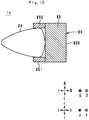
- FIG. 10 is a schematic view of the rider-only single seat 24 and the carrying structure 80 of the leaning vehicle 1c as seen from the upward direction u.
- the configuration except for that of the rider-only single seat 24 and the carrying structure 80 is omitted.
- the components are not drawn to scale because of their simplified representations.
- the leaning vehicle 1c is different from the leaning vehicle 1a in the structure of the carrying structure 80.
- the carrying structure 80 of the leaning vehicle 1c includes a left protrusion 851 and a right protrusion 852 in addition to the storage box 850.
- the left protrusion 851 protrudes from the left end portion of the storage box 850 in the frontward direction f.
- the left protrusion 851 is disposed to the left of the rear portion of the rider-only single seat 24 in the leftward direction 1.
- the front portion of the rider-only single seat 24 corresponds to the front half of the rider-only single seat 24.
- the rear portion of the rider-only single seat 24 corresponds to the rear half of the rider-only single seat 24.
- the left protrusion 851 prevents the rider 500 (not illustrated in FIG. 10 ) from displacing from the rider-only single seat 24 in the leftward direction 1.
- the inside of the left protrusion 851 is an empty space.
- the space in the left protrusion 851 is connected with the space in the storage box 850.
- the right protrusion 852 protrudes from the right end portion of the storage box 850 in the frontward direction f.
- the right protrusion 852 is disposed to the right of the rear portion of the rider-only single seat 24 in the rightward direction r. In this way, the right protrusion 852 prevents the rider 500 (not illustrated in FIG. 10 ) from displacing from the rider-only single seat 24 in the rightward direction r.
- the inside of the right protrusion 852 is an empty space. The space in the right protrusion 852 is connected with the space in the storage box 850.
- the rear mounted load 90 (not illustrated in FIG. 10 ) is stored in the carrying structure 80. At this time, the rear mounted load 90 is carried on the bottom surface among inner peripheral surfaces in the carrying structure 80. Accordingly, in the leaning vehicle 1c, the carrying section 85 corresponds to the bottom surface among inner peripheral surfaces of the carrying structure 80. However, the carrying section 85 is disposed behind the rider-only single seat 24 in the backward direction b. Accordingly, the carrying section 85 includes the bottom surface among inner peripheral surfaces of the storage box 850, and does not include the bottom surface among inner peripheral surfaces of the left protrusion 851 and the bottom surface among inner peripheral surfaces of the right protrusion 852. The rest of the configuration of the leaning vehicle 1c is similar to that of the leaning vehicle 1a, and thus explanation thereof will be omitted.
- the center of rear wheel 4 in the left-right direction lr coincides with the center between the left front wheel 31 and the right front wheel 32 in the left-right direction lr.
- the center of rear wheel 4 in the left-right direction lr may not be coincide with the center between the left front wheel 31 and the right front wheel 32 in the left-right direction lr.
- the link mechanism 5 is disposed above the left front wheel 31 and the right front wheel 32 in the upward direction u.
- the link mechanism 5 may be disposed between the left front wheel 31 and the right front wheel 32.
- the link mechanism 5 overlaps the left front wheel 31 and the right front wheel 32.
- the left side member 53 also functions as the left shock absorber 33.
- the right side member 54 also functions as right shock absorber 34.
- the link mechanism 5 is a parallelogram linkage link mechanism.
- the link mechanism 5 may be a link mechanism of a double wishbone type.
- the upper cross member 51 is a single plate-like member
- the lower cross member 52 includes the front lower cross member 522A and the rear lower cross member 522B.
- the upper cross member 51 may include a front upper cross member and a rear upper cross member.
- the lower cross member 52 may be a single plate-like member. At least one of the upper cross member 51 and the lower cross member 52 may include a left plate-like member supported by the headpipe 211 and the left side member 53 and a right plate-like member supported by the headpipe 211 and the right side member 54.
- the handlebar 23 is made up of a single member extending in the left-right direction LR.
- the handlebar 23 may have a configuration in which a left handlebar section operated by the rider 500 with his/her left hand and a right handlebar section operated by the rider 500 with his/her right hand are separately provided insofar as a steering force for rotating the left front wheel 31 and the right front wheel 32 can be input.
- the link mechanism 5 is supported by the headpipe 211, which is an example of the link support portion.
- the link mechanism 5 may be supported by other portions than the headpipe 211 in the vehicle body frame 21.
- the power unit 25 is supported by the vehicle body frame 21. Accordingly, the power unit 25 may be fixed directly by the vehicle body frame 21 or may be fixed to a swing arm rotatably supported by the vehicle body frame 21.
- the power unit 25 of the leaning vehicles 1 and 1a to 1c may be a combination of an electric motor and a battery.
- the rider-only single seat 24 may be located above a rotating shaft of the electric motor and the battery in the upward direction u.
- the leaning vehicles 1 and 1a to 1c in turning left, the left front wheel 31, the right front wheel 32, the vehicle body frame 21, and the rear wheel 4 lean in the leftward direction L. In turning right, the left front wheel 31, the right front wheel 32, the vehicle body frame 21, and the rear wheel 4 lean in the rightward direction R. In this way, the rear wheel 4 leans along with the vehicle body frame 21 in the leftward direction L or the rightward direction R. Accordingly, the leaning vehicles 1 and 1a to 1c do not include a type of vehicle in which the vehicle body frame 21 twists in turning left or turning right and thereby the rear wheel 4 does not lean.
- the distance L4 in the front-back direction fb from the seat rear end SB to the front end of the carrying section 85 may be zero.
- the seat rear end SB and the carrying section 85 may be in contact with each other in the front-back direction fb.
- the rear carrier 81 is made from a metal pipe.
- the structure of the rear carrier 81 is not limited to that illustrated in FIG. 6 .
- the rear carrier 81 may be made from a wood sheet, a metal sheet, a resin sheet, or other materials.
Landscapes
- Engineering & Computer Science (AREA)
- Mechanical Engineering (AREA)
- Automatic Cycles, And Cycles In General (AREA)
- Seats For Vehicles (AREA)
Abstract
Description
- The present teaching relates to a leaning vehicle provided with a right front wheel, a left front wheel and a rear wheel.
- As inventions for leaning vehicles in the past, three-wheeled vehicles described in
Patent Literature 1 andPatent Literature 2 are known, for example. The three-wheeled vehicles are each provided with a handlebar, a vehicle body frame, a left front wheel, a right front wheel, and a rear wheel. A rider operates the handlebar to rotate the left front and right front wheels in a counterclockwise direction when the three-wheeled vehicle is viewed from above. Further, the rider leans the vehicle body frame in a three-wheeled-vehicle leftward direction. This causes the three-wheeled vehicle to turn to the left. Similarly, the rider operates the handlebar to rotate the left front and right front wheels in a clockwise direction when the three-wheeled vehicle is viewed from above. Further, the rider leans the vehicle body frame in a three-wheeled-vehicle rightward direction. This causes the three-wheeled vehicle to turn to the right. -
- Patent Literature 1: Japanese Patent Application Publication No.
2005-247303 - Patent Literature 2:
U.S. Patent No. 8814186 - When the three-wheeled vehicles described in
Patent Literature 1 andPatent Literature 2 are to be used on business, on commuting, or other purposes, there is an increasing demand for carrying a load. - Therefore, an object of the present teaching is to increase a load capacity for a rear mounted load on a leaning vehicle while preventing the leaning vehicle from increasing in size, the leaning vehicle including a left front wheel, a right front wheel, a rear wheel, and a link mechanism, the link mechanism causing an axle of the left front wheel to be positioned further upward in a vehicle-body-frame upward direction than an axle of the right front wheel to lean a vehicle body frame in a leaning-vehicle leftward direction and causing the axle of the right front wheel to be positioned further upward in a vehicle-main-body upward direction than the axle of the left front wheel to lean a vehicle main body in a leaning-vehicle rightward direction. The rear mounted load refers to a load carried near and above the rear wheel.
- For the leaning vehicle provided with a left front wheel, a right front wheel, a rear wheel, and a link mechanism, the present inventors have studied to increase a carrying section provided behind a passenger seat in a leaning-vehicle backward direction for improving user convenience. However, simply increasing the carrying section leads to a backward extension of a rear portion of the leaning vehicle or widening of the rear portion of the leaning vehicle in a left-right direction. As a result, the size of the leaning vehicle is increased.
- Accordingly, the present inventors have conducted a study introducing a different technical concept from those that have been proposed, which intend to improve and increase the carrying section of the leaning vehicle. Specifically, the present inventors have conducted a study introducing a technical concept to newly construct a layout of the left front wheel, the right front wheel, the rear wheel, the link mechanism, the seat, and the carrying section primarily for increasing the carrying section.
- To increase the carrying section of the leaning vehicle provided with a left front wheel, a right front wheel, and a rear wheel, the present inventors have first examined a weight distribution of the leaning vehicle. As a result, in the leaning vehicle provided with a left front wheel, a right front wheel, and a rear wheel, it has been found that a total percentage of the left and right front wheels in the weight distribution is larger than a percentage of a front wheel in a weight distribution of a leaning vehicle provided with one front wheel and one rear wheel. Accordingly, the present inventors have studied how a load is to be carried in a favorable manner on the leaning vehicle that has a large total percentage of the left and right front wheels in the weight distribution.
- In the case of the leaning vehicle provided with a left front wheel, a right front wheel, and a rear wheel, the total percentage of the left and right front wheels in the weight distribution is larger, as described above. In other words, the percentage of the rear wheel in the weight distribution is smaller in the leaning vehicle provided with a left front wheel, a right front wheel, and a rear wheel. As a result, the present inventors have realized that the percentage of the rear wheel in the weight distribution may be increased by carrying a load near and above the rear wheel (hereinafter referred to as "rear mounted load").
- Meanwhile, the leaning vehicle is either in a state in which the vehicle is carrying a rear mounted load (carrying state) or in a state in which the vehicle is not carrying a rear mounted load (non-carrying state). In some cases, it is desirable that no large change occurs in the percentage of the left and right front wheels in the weight distribution (hereinafter referred to as "front weight distribution") nor the percentage of the rear wheel in the weight distribution (hereinafter referred to as "rear weight distribution") between the carrying state and the non-carrying state. In this case, it is desirable that the rear mounted load is carried at a position where no large change occurs in the front weight distribution nor the rear weight distribution between the carrying state and the non-carrying state. Accordingly, the present inventors have studied a position where the rear mounted load is to be carried.
- As described above, in the leaning vehicle, the rear mounted load is carried near and above the rear wheel. Because of this, a weight applied to the rear wheel varies between the carrying state and the non-carrying state. However, the present inventors considered that a large change in the front weight distribution and the rear weight distribution can be suppressed by reducing a rate of variation of the weight applied to the rear wheel between the carrying state and the non-carrying state. Then, as described below, the present inventors considered that the seat may be positioned in the leaning vehicle such that a larger part of the weight of a rider is applied to the rear wheel.
- For example, a case in which a rider weighing 60kg sits on the seat of the leaning vehicle will be explained as an example. In a first example, consider a leaning vehicle in which a weight of 20kg is applied to the left and right front wheels and a weight of 40kg is applied to the rear wheel. In a second example, consider a leaning vehicle in which a weight of 5kg is applied to the left and right front wheels and a weight of 55kg is applied to the rear wheel. In the first example, when a rear mounted load of 20kg is carried, the weight applied to the rear wheel increases 50%. In the second example, when a rear mounted load of 20kg is carried, the weight applied to the rear wheel increases 36%. In this way, as the weight of the rider applied to the rear wheel increases, the rate of variation of the weight applied to the rear wheel is reduced between the carrying state and the non-carrying state. Then, the present inventors have considered that the seat for a rider to sit may be positioned near the rear wheel in order to suppress a large change in the front weight distribution and the rear weight distribution between the carrying state and the non-carrying state.
- For the leaning vehicle with a large change in the front weight distribution and the rear weight distribution being suppressed between the carrying state and the non-carrying state as described above, the present inventors have studied how a larger amount of rear mounted load can be carried without increasing the size of the leaning vehicle. Then, the present inventors have studied modes of use of leaning vehicles for business and commuting uses. The present inventors have realized that, in most cases, a leaning vehicle for business and commuting uses is ridden by only the rider without a passenger. Accordingly, the present inventors have conceived to arrange a rider-only single seat and a carrying section for rear mounted load behind the rider-only single seat.
- The present teaching adopts the following configuration in order to solve the above problem.
-
- (1) A leaning vehicle including:
- a vehicle body frame that leans in a leaning-vehicle leftward direction in turning left and leans in a leaning-vehicle rightward direction in turning right;
- a left front wheel disposed further leftward in a vehicle-body-frame leftward direction than a center of the vehicle-body-frame in a vehicle-body-frame left-right direction, the left front wheel being rotatable around a left-front-wheel axle;
- a right front wheel disposed further rightward in a vehicle-body-frame rightward direction than a center of the vehicle-body-frame in the vehicle-body-frame left-right direction, the right front wheel being rotatable around a right-front-wheel axle;
- a link mechanism that supports the left front wheel and the right front wheel, the link mechanism allowing the left-front-wheel axle to be located further upward in a vehicle-body-frame upward direction than the right-front-wheel axle to lean the vehicle body frame in the leaning-vehicle leftward direction in turning left, the link mechanism allowing the right-front-wheel axle to be located further upward in the vehicle-body-frame upward direction than the left-front-wheel axle to lean the vehicle body frame in the leaning-vehicle rightward direction in turning right;
- a rear wheel disposed further backward in a vehicle-body-frame backward direction than the left front wheel and the right front wheel and rotatable around a rear wheel axle, the rear wheel being caused to lean along with the vehicle body frame in the leaning-vehicle leftward direction in turning left and to lean along with the vehicle body frame in the leaning-vehicle rightward direction in turning right;
- a steering mechanism for steering the left front wheel and the right front wheel;
- a rider-only single seat supported by the vehicle body frame, the rider-only single seat being only for a rider who steers the steering mechanism to sit; and
- a carrying section disposed further backward in the vehicle-body-frame backward direction than the rider-only single seat, the carrying section being loaded with a rear mounted load thereon,
- wherein in a state in which the link mechanism causes the left-front-wheel axle and the right-front-wheel axle to be at a same level in a vehicle-body-frame up-down direction and the left front wheel, the right front wheel, and the rear wheel are grounded, Formulae (a), (b), and (c) hold:



- where L1 is defined as a distance in a vehicle-body-frame front-back direction from a rear end of the rider-only single seat to the rear wheel axle,
- L2 is defined as a distance in the vehicle-body-frame front-back direction from the rear end of the rider-only single seat to a wheelbase center located at a center between the left-front-wheel axle or the right-front-wheel axle and the rear wheel axle in the vehicle-body-frame front-back direction,
- L3 is defined as a distance in the vehicle-body-frame front-back direction from the rear end of the rider-only single seat to a center of the carrying section in the vehicle-body-frame front-back direction,
- L4 is defined as a distance in the vehicle-body-frame front-back direction from the rear end of the rider-only single seat to a front end of the carrying section, and
- L5 is defined as a distance in the vehicle-body-frame front-back direction from a front end of a seating surface that allows the rider to sit in the rider-only single seat to a hip point of the rider sitting on the rider-only single seat.
According to the leaning vehicle of (1), the rate of variation of the weight applied to the rear wheel between the carrying state and the non-carrying state is reduced. Specifically, in the leaning vehicle of (1), such a state in which the link mechanism causes the left-front-wheel axle and the right-front-wheel axle to be at a same level in a vehicle-body-frame up-down direction and the left front wheel, the right front wheel, and the rear wheel are grounded means that the vehicle body frame is upright. In the leaning vehicle of (1), when the vehicle body frame is upright, the distance L1 in the vehicle-body-frame front-back direction from the rear end of the rider-only single seat to the rear wheel axle is shorter than the distance L2 in the vehicle-body-frame front-back direction from the rear end of the rider-only single seat to the wheelbase center. In other words, the rear end of the rider-only single seat is resultantly located in a rear half from the wheelbase, and thus the rider-only single seat is located near the rear wheel axle. In this way, the center of gravity of the rider sitting on the rider-only single seat is located near the rear wheel axle.
Further, in the leaning vehicle of (1), when the vehicle body frame is upright, the distance L3 in the vehicle-body-frame front-back direction from the rear end of the rider-only single seat to the center of the carrying section in the vehicle-body-frame front-back direction is shorter than the distance L2 in the vehicle-body-frame front-back direction from the rear end of the rider-only single seat to the wheelbase center. In other words, the rider-only single seat is located near the carrying section. In this way, the center of gravity of the rider sitting on the rider-only single seat is located near the center of gravity of a rear mounted load carried on the carrying section. As described above, since the center of gravity of the rider sitting on the rider-only single seat is located near the rear wheel axle, the center of gravity of a rear mounted load carried on the carrying section is also located near the rear wheel axle.
As described above, in the leaning vehicle of (1), the center of gravity of the rider sitting on the rider-only single seat and the center of gravity of a rear mounted load carried on the carrying section is located near the rear wheel axle. Accordingly, most of the weight of the rider and the rear mounted load is applied to the rear wheel. As a result, the rate of variation of the weight applied to the rear wheel between the carrying state and the non-carrying state is reduced.
Further, according to the leaning vehicle of (1), the load capacity for a rear mounted load can be increased while preventing the leaning vehicle from increasing in size. Specifically, the distance L4 in the vehicle-body-frame front-back direction from the rear end of the rider-only single seat to the front end of the carrying section is shorter than the distance L5 in the vehicle-body-frame front-back direction from the front end of the seating surface that allows the rider to sit in the rider-only single seat to the hip point of the rider sitting on the rider-only single seat. The distance L5 in the vehicle-body-frame front-back direction from the front end of the seating surface to the hip point of the rider sitting on the rider-only single seat corresponds to a space where one person can sit. Accordingly, in the leaning vehicle of (1), there is no space where one person can sit between the rear end of the rider-only single seat and the front end of the carrying section. As such, the carrying section is disposed behind the rear end of the rider-only single seat in the vehicle-body-frame backward direction with almost no wasteful space. As a result, in the leaning vehicle of (1), a larger amount of rear mounted load can be carried without increasing the size of the leaning vehicle. - (2) The leaning vehicle of (1), wherein
the vehicle body frame includes a link support portion,
the link mechanism includes: an upper cross member disposed further upward in the vehicle-body-frame upward direction than the left front wheel and the right front wheel, the upper cross member being rotatably supported in an intermediate portion thereof by an upper portion of the link support portion; a lower cross member disposed further downward in a vehicle-body-frame downward direction than the upper cross member and further upward in the vehicle-body-frame upward direction than the left front wheel and the right front wheel, the lower cross member being rotatably supported in an intermediate portion thereof by a lower portion of the link support portion; a left side member rotatably supported in an upper portion thereof by a left portion of the upper cross member, the left side member being rotatably supported in a lower portion thereof by a left portion of the lower cross member; and a right side member rotatably supported in an upper portion thereof by a right portion of the upper cross member, the right side member being rotatably supported in a lower portion thereof by a right portion of the lower cross member, the left front wheel is supported by the left side member, and the right front wheel is supported by the right side member.
According to the leaning vehicle of (2), in such a leaning vehicle provided with a parallelogram linkage link mechanism, a larger amount of rear mounted load can be carried without increasing the size of the leaning vehicle. - (3) The leaning vehicle of (1) or (2), wherein
a storage space is provided below the rider-only single seat in the vehicle-body-frame downward direction, and
the rider-only single seat is capable of assuming a closed state in which the storage space is not exposed to outside of the leaning vehicle and an open state in which the storage space is exposed to outside of the leaning vehicle.
According to the leaning vehicle of (3), since a storage space is provided below the rider-only single seat in the vehicle-body-frame downward direction, a storage load can be stored in the storage space. - (4) The leaning vehicle of any one of (1) to (3), wherein
a length of the rider-only single seat in the vehicle-body-frame front-back direction is shorter than a length from the wheelbase center to the rear wheel axle in the vehicle-body-frame front-back direction.
According to the leaning vehicle of (4), since the length of the rider-only single seat in the vehicle-body-frame front-back direction is short, only the rider is allowed to sit on the rider-only single seat but no passenger is allowed to sit on the rider-only single seat. - (5) The leaning vehicle of any one of (1) to (4), further including an engine for generating a driving force to rotate the rear wheel, the engine having a crankshaft, wherein
when the engine is seen from the vehicle-body-frame leftward or rightward direction, the rider-only single seat is disposed above a central axis of rotation of the crankshaft in the vehicle-body-frame upward direction. - According to the leaning vehicle of (5), the center of gravity of the rider sitting on the rider-only single seat is located near the rear wheel axle. Specifically, in the leaning vehicle of (5), when the engine is seen from the vehicle-body-frame leftward or rightward direction, the rider-only single seat is disposed above the central axis of rotation of the crankshaft of a power unit, as the engine, in the vehicle-body-frame upward direction. Accordingly, the distance between the rider-only single seat and the power unit is short in the vehicle-body-frame front-back direction. The power unit is disposed near the rear wheel. As a result, the distance between the rider-only single seat and the rear wheel axle is short in the vehicle-body-frame front-back direction. Accordingly, in the leaning vehicle of (5), the center of gravity of the rider sitting on the rider-only single seat is located near the rear wheel axle.
- The above-described object of the invention and other objects, features, aspects and advantages will be apparent from detailed descriptions of embodiments of the invention made with reference to attached drawings.
- As used herein, the term "and/or" includes any and all combinations of one or more of the associated listed items.
- As used herein, the terms "including," "comprising" or "having" and variations thereof specify the presence of stated features, steps, operations, elements, components, and/or their equivalents but do not preclude the presence or addition of one or more other features, steps, operations, elements, components, and/or groups thereof.
- Unless otherwise defined, all terms (including technical and scientific terms) used herein have the same meaning as commonly understood by one having ordinary skill in the art to which this invention belongs.
- It will be further understood that terms, such as those defined in commonly used dictionaries, should be interpreted as having a meaning that is consistent with their meaning in the context of the relevant art and the present disclosure and will not be interpreted in an idealized or overly formal sense unless expressly so defined herein.
- In describing the invention, it will be understood that a number of techniques and steps are disclosed. Each of these has individual benefit and each can also be used in conjunction with one or more, or in some cases all, of the other disclosed techniques. Accordingly, for the sake of clarity, this description will refrain from repeating every possible combination of the individual steps in an unnecessary fashion. Nevertheless, the specification and claims should be read with the understanding that such combinations are entirely within the scope of the invention and the claims.
- In the following description, for purposes of explanation, numerous specific details are set forth in order to provide a thorough understanding of the present teaching. It will be evident, however, to one skilled in the art that the present teaching may be practiced without these specific details. The present disclosure is to be considered as an exemplification of the invention, and is not intended to limit the invention to the specific embodiments illustrated by the figures or description below.
- According to the present teaching, a load capacity for a rear mounted load on a leaning vehicle can be increased while preventing the leaning vehicle from increasing in size, the leaning vehicle including a left front wheel, a right front wheel, a rear wheel, and a link mechanism, the link mechanism causing an axle of the left front wheel to be positioned further upward in a vehicle-body-frame upward direction than an axle of the right front wheel to lean a vehicle body frame in a leaning-vehicle leftward direction and causing the axle of the right front wheel to be positioned further upward in a vehicle-main-body upward direction than the axle of the left front wheel to lean a vehicle main body in a leaning-vehicle rightward direction.
-
- [
FIG. 1] FIG. 1 is a view of a leaningvehicle 1 as seen from a vehicle-body-frame (21) leftward direction with avehicle body frame 21 being upright. - [
FIG. 2] FIG. 2 is a view of a front portion of the leaningvehicle 1 as seen from a vehicle-body-frame (21) frontward direction with thevehicle body frame 21 being upright. - [
FIG. 3] FIG. 3 is a view of the front portion of the leaningvehicle 1 as seen from an upward direction u with thevehicle body frame 21 being upright. - [
FIG. 4] FIG. 4 is a view of the front portion of the leaningvehicle 1 as seen from the upward direction u with the leaningvehicle 1 being steered to turn left. - [
FIG. 5] FIG. 5 is a view of the front portion of the leaningvehicle 1 as seen from a frontward direction f with thevehicle body frame 21 leaning in a leftward direction L. - [
FIG. 6] FIG. 6 is a view of the leaningvehicle 1 as seen from the upward direction u. - [
FIG. 7] FIG. 7 is a view of the leaningvehicle 1 as seen from theleftward direction 1 with thevehicle body frame 21 being upright. - [
FIG. 8] FIG. 8 is a schematic view of a leaning vehicle 1a as seen from theleftward direction 1. - [
FIG. 9] FIG. 9 is a schematic view of a leaning vehicle 1b as seen from theleftward direction 1. - [
FIG. 10] FIG. 10 is a schematic view of a rider-onlysingle seat 24 and a carryingstructure 80 of a leaning vehicle 1c as seen from the upward direction u. - The overall configuration of a leaning
vehicle 1 according to an embodiment will now be described with reference toFIGS. 1 and2 . In the embodiment, a three-wheeled vehicle that has a leanable vehicle body frame, two front wheels and one rear wheel is illustrated as an example of the leaningvehicle 1.FIG. 1 is a view of the leaningvehicle 1 as seen from the vehicle-body-frame (21) leftward direction with thevehicle body frame 21 being upright.FIG. 2 is a view of the front portion of the leaningvehicle 1 as seen from the vehicle-body-frame (21) frontward direction with thevehicle body frame 21 being upright.FIG. 2 illustrates a state in which thevehicle body 22 is transparent. Hereinafter, the leaning-vehicle (1) frontward direction is referred to as a frontward direction "F". The leaning-vehicle (1) backward direction is referred to as a backward direction "B". The leaning-vehicle (1) leftward direction is referred to as a leftward direction "L". The leaning-vehicle (1) rightward direction is referred to as a rightward direction "R". The leaning-vehicle (1) upward direction is referred to as an upward direction "U". The leaning-vehicle (1) downward direction is referred to as a downward direction "D". The leaning-vehicle (1) front-back direction is referred to as a front-back direction "FB". The leaning-vehicle (1) left-right direction is referred to as a left-right direction "LR". The leaning-vehicle (1) up-down direction is referred to as an up-down direction "UD". The leaning-vehicle (1) frontward direction refers to the traveling direction of the leaningvehicle 1. The leaning-vehicle (1) backward direction refers to a direction opposite to the traveling direction of the leaningvehicle 1. The leaning-vehicle (1) leftward direction refers to the leftward direction with respect to a rider who straddles the leaningvehicle 1. The leaning-vehicle (1) rightward direction refers to the rightward direction with respect to the rider who straddles the leaningvehicle 1. The leaning-vehicle (1) upward direction refers to the upward direction with respect to a rider who straddles the leaningvehicle 1. The leaning-vehicle (1) downward direction refers to the downward direction with respect to a rider who straddles the leaningvehicle 1. - Further, in the leaning
vehicle 1, thevehicle body frame 21 can lean in the leftward direction L or the rightward direction R. When thevehicle body frame 21 leans in the leftward direction L or the rightward direction R, the vehicle-body-frame (21) up-down and left-right directions do not coincide with the leaning-vehicle (1) up-down direction UD and the leaning-vehicle (1) left-right direction LR, respectively. On the other hand, the vehicle-body-frame (21) up-down and left-right directions in an upright state coincide with the leaning-vehicle (1) up-down direction UD and the leaning-vehicle (1) left-right direction LR, respectively. Hereinafter, the vehicle-body-frame (21) frontward direction is referred to as a frontward direction "f". The vehicle-body-frame (21) backward direction is referred to as a backward direction "b". The vehicle-body-frame (21) leftward direction is referred to as a leftward direction "l". The vehicle-body-frame (21) rightward direction is referred to as a rightward direction "r". The vehicle-body-frame (21) upward direction is referred to as an upward direction "u". The vehicle-body-frame (21) downward direction is referred to as a downward direction "d". The vehicle-body-frame (21) front-back direction is referred to as a front-back direction "fb". The vehicle-body-frame (21) left-right direction is referred to as a left-right direction "lr". The vehicle-body-frame (21) up-down direction is referred to as an up-down direction "ud". - Hereinafter, an upper end of a component denotes an end of the top portion of the component. A lower end of a component denotes an end of the bottom portion of the component. A front end of a component denotes an end of the front of the component. The rear end of a component denotes an end of the rear of the component. The left end of a component denotes an end of the left of the component. The right end of a component denotes an end of the right of the component. The upper end portion of a component denotes the upper end and its vicinity of the component. The lower end portion of a component denotes the lower end and its vicinity of the component. The front end portion of a component denotes the front end and its vicinity of the component. The rear end portion of a component denotes the rear end and its vicinity of the component. The left end portion of a component denotes the left end and its vicinity of the component. The right end portion of a component denotes the right end and its vicinity of the component. The component denotes the leaning
vehicle 1 and a member constituting the leaningvehicle 1. - An axis or a member extending in the front-back direction does not necessarily refer to only an axis or a member that is in parallel with the front-back direction. An axis or a member extending in the front-back direction refers to an axis or a member that is inclined within a range of ±45° with respect to the front-back direction. Similarly, an axis or a member extending in the up-down direction refers to an axis or a member that is inclined within a range of ±45° with respect to the up-down direction. An axis or a member extending in the left-right direction refers to an axis or a member that is inclined within a range of ±45° with respect to the left-right direction. Further, an "upright" state of the
vehicle body frame 21 means a state in which the front wheels are not steered nor leaning while no rider is riding on nor no fuel is stored in the leaningvehicle 1. - As used herein, a phrase "a first member is supported by a second member" includes both a case in which the first member is attached to (i.e. fixed to) the second member unmovably with respect to the second member and a case in which the first member is attached to the second member movably with respect to the second member. Further, a phrase "a first member is supported by a second member" includes both a case in which the first member is directly attached to the second member and a case in which the first member is attached to the second member with an intervening third member.
- As illustrated in
FIG. 1 , the leaningvehicle 1 includes a vehiclemain body section 2, a left front wheel 31 (seeFIG. 2 ), a right front wheel 32 (seeFIG. 2 ), arear wheel 4, alink mechanism 5, and asteering mechanism 7. The vehiclemain body section 2 includes thevehicle body frame 21, thevehicle body cover 22, the rider-onlysingle seat 24, and thepower unit 25. - The
vehicle body frame 21 leans in the leftward direction L in turning left. Thevehicle body frame 21 leans in the rightward direction R in turning right. Thevehicle body frame 21 includes aheadpipe 211, adownframe 212, anunderframe 214, and arearframe 215. InFIG. 1 , portions of thevehicle body frame 21 hidden by thevehicle body cover 22 are illustrated in dashed lines. Thevehicle body frame 21 supports the rider-onlysingle seat 24, thepower unit 25, and the like. - The
headpipe 211 is disposed in the front portion of the leaningvehicle 1. The front portion of the leaningvehicle 1 refers to a portion located further frontward than the front end of the rider-onlysingle seat 24 in the frontward direction f in the leaningvehicle 1. The rear portion of the leaningvehicle 1 refers to a portion located further backward than the front end of the rider-onlysingle seat 24 in the backward direction b in the leaningvehicle 1. When thevehicle body frame 21 is seen from the leftward direction l or the rightward direction r, theheadpipe 211 is inclined with respect to the up-down direction ud such that the upper end portion of theheadpipe 211 is located further backward than the lower end portion of theheadpipe 211 in the backward direction b. Thesteering mechanism 7 and thelink mechanism 5 are disposed around theheadpipe 211. A steeringshaft 60 of thesteering mechanism 7 is rotatably inserted in theheadpipe 211. Thelink mechanism 5 is supported by theheadpipe 211. - The
downframe 212 is disposed further backward than theheadpipe 211 in the backward direction b. Thedownframe 212 has a cylindrical shape extending in the up-down direction ud. The upper end portion of thedownframe 212 is located behind the lower end portion of theheadpipe 211 in the backward direction b. Further, the upper end portion of thedownframe 212 is fixed to the lower end portion of theheadpipe 211 by an unillustrated connection. - The
underframe 214 extends from the lower end portion of thedownframe 212 in the backward direction b and the upward direction u. Therearframe 215 extends from the rear end of theunderframe 214 in the backward direction b and the upward direction u. - The
vehicle body frame 21 is covered with thevehicle body cover 22. Thevehicle body cover 22 includes afront cover 221, afront fender pair 223 of right and left front fenders, and aleg shield 225. Thefront cover 221 is located in front of the rider-onlysingle seat 24 in the frontward direction f. Thefront cover 221 covers at least part of thesteering mechanism 7 and at least part of thelink mechanism 5. - The
power unit 25 includes the engine, a transmission, and the like. Thepower unit 25 generates a driving force to rotate therear wheel 4. The engine has a crankshaft. The central axis of rotation of the crankshaft is a central axis Ax extending in the left-right direction lr. - As illustrated in
FIG. 2 , theleft front wheel 31 is disposed further leftward in theleftward direction 1 than the center C0 of thevehicle body frame 21 in the left-right direction lr. Theleft front wheel 31 is rotatable around the left-front-wheel axle 314. As illustrated inFIG. 2 , theright front wheel 32 is disposed further rightward in the rightward direction r than the center C0 of thevehicle body frame 21 in the left-right direction lr. Theright front wheel 32 is rotatable around the right-front-wheel axle 324. Theleft front wheel 31 and theright front wheel 32 are symmetrically disposed with respect to the center C0. - The
front fender pair 223 includes a leftfront fender 227 and a rightfront fender 228. The leftfront fender 227 is disposed above theleft front wheel 31 in the upward direction u. The rightfront fender 228 is disposed above theright front wheel 32 in the upward direction u. - The
rear wheel 4 is disposed further backward than theleft front wheel 31 and theright front wheel 32 in the backward direction b. Therear wheel 4 is rotatable around therear wheel axle 414. Therear wheel 4 is rotated by a driving force generated by thepower unit 25. - The rider-only
single seat 24 is disposed between the left-front-wheel axle 314 or the right-front-wheel axle 324 and therear wheel axle 414 in the front-back direction fb. Further, when the leaningvehicle 1 is seen from theleftward direction 1 or the rightward direction r, the rider-onlysingle seat 24 is disposed above the central axis Ax in the upward direction u. The rider-onlysingle seat 24 is supported by thevehicle body frame 21. The rider-onlysingle seat 24 is a seat only for arider 500 who steers thesteering mechanism 7 described later to sit. Accordingly, the rider-onlysingle seat 24 is designed to have a short length in the front-back direction fb. Specifically, a length L11 of the rider-onlysingle seat 24 in the front-back direction fb is shorter than a length L12 from a wheelbase center WBC to therear wheel axle 414 in the front-back direction fb. The wheelbase center WBC refers to a central point between the left-front-wheel axle 314 or the right-front-wheel axle 324 and therear wheel axle 414 in the front-back direction fb. - The rider-only
single seat 24 includes a seating surface 24a and a back rest 24b. The seating surface 24a is an area that pushes the hip of therider 500 in the upward direction u. Accordingly, the seating surface 24a is a plane facing the upward direction u. However, the seating surface 24a may not be completely flat but may be substantially flat. Accordingly, the seating surface 24a may have a slightly curved shape or a slightly textured shape for slip resistance. However, the distance between the upper end of the seating surface 24a and the lower end of the seating surface 24a in the up-down direction ud is equal to or less than 5 cm. Further, the normal of the seating surface 24a may not coincide with the upward direction u. The normal of the seating surface 24a refers to a normal of a plane that includes the front end of the seating surface 24a (hereinafter referred to as "seating surface front end SFF") and the rear end of the seating surface 24a (hereinafter referred to as "seating surface rear end SFB") and that is in parallel with the left-right direction lr. The normal of the seating surface 24a may be inclined with respect to the upward direction u to the extent that therider 500 can sit. Specifically, the normal of the seating surface 24a may for example be inclined forward up to 10° with respect to the upward direction u. - Here, description will be made as to the seating surface front end SFF and the seating surface rear end SFB. In the rider-only
single seat 24, an arcuate surface S1 is arranged in front of the seating surface 24a in the frontward direction f. The seating surface front end SFF corresponds to the rear end of the arcuate surface S1. Further, in the rider-onlysingle seat 24, an arcuate surface S2 is arranged behind the seating surface 24a in the backward direction b. The seating surface rear end SFB corresponds to the front end of the arcuate surface S2. Further, the back rest 24b is a portion located further backward than the front end of arcuate surface S2 in the backward direction b in the rider-onlysingle seat 24. The back rest 24b supports therider 500 in his/her hip from the backward direction b. - A point where a hip joint of the
rider 500 is located when therider 500 is sitting on the rider-onlysingle seat 24 is referred to as a hip point HP. When seen from theleftward direction 1, the hip point HP is located 20 cm behind the front end of seating surface 24a of the rider-onlysingle seat 24 in the backward direction b. - Only
rider 500 sits on the seating surface 24a. Accordingly, the seating surface 24a is designed to have a short length in the front-back direction fb. Specifically, the length of the seating surface 24a in the front-back direction fb is in a range of 20 cm or more and 45 cm or less, for example. Further, the rider-onlysingle seat 24 includes only one seating surface 24a without including a plurality of seating surfaces. The reference to a plurality of seating surfaces means that two or more adjacent planes in the front-back direction fb are disposed at different levels in the up-down direction ud. The length of one of the two or more planes in the front-back direction fb is equal to or larger than 10 cm. The length of the upper surface of the back rest 24b in the front-back direction is shorter than 10 cm. As such, the upper surface of the back rest 24b is not included in the two or more planes. - As described above, the rider-only
single seat 24 does not allow a passenger to sit. Further, the leaningvehicle 1 is provided with no other seats than the rider-onlysingle seat 24. Accordingly, the seating capacity of the leaningvehicle 1 is one person. For example, the seating capacity of the leaningvehicle 1 can be confirmed in an instruction manual or an automobile inspection certificate. - The
steering mechanism 7 will now be described with reference toFIGS. 2 and3. FIG. 3 is a view of the front portion of the leaningvehicle 1 as seen from an upward direction u with thevehicle body frame 21 being upright.FIG. 3 illustrates a state in which thevehicle body cover 22 is transparent. - The
steering mechanism 7 steers theleft front wheel 31 and theright front wheel 32. As illustrated inFIGS. 2 and3 , thesteering mechanism 7 includes a steeringforce transmitting mechanism 6, aleft shock absorber 33, and aright shock absorber 34. - The
left shock absorber 33 movably supports theleft front wheel 31 with respect to thevehicle body frame 21 in the up-down direction ud. Theleft shock absorber 33 includes a left lower portion 33a, a leftupper portion 33b, and aleft support portion 33c. The left lower portion 33a extends in the up-down direction ud. Theleft support portion 33c is disposed in the lower end portion of the left lower portion 33a. Theleft support portion 33c rotatably supports theleft front wheel 31. Theleft front wheel 31 is rotatable around the left-front-wheel axle 314 as the central axis. The left-front-wheel axle 314 extends from theleft support portion 33c in theleftward direction 1. The leftupper portion 33b extends in the up-down direction ud. The leftupper portion 33b is disposed above the left lower portion 33a in the upward direction u with the vicinity of the lower end of the leftupper portion 33b being inserted in the left lower portion 33a. The upper end portion of the leftupper portion 33b is fixed to aleft bracket 317 described later. In other words, the leftupper portion 33b is supported by aleft side member 53 described later. - The
left shock absorber 33 is a so-called telescopic type shock absorber. For example, theleft shock absorber 33 is made up of a combination of a damper and a spring. The leftupper portion 33b moves relative to the left lower portion 33a in the direction in which the left lower portion 33a extends, and correspondingly theleft shock absorber 33 extends and contracts in the same direction. In this way, theleft shock absorber 33 buffers displacement of theleft front wheel 31 with respect to the leftupper portion 33b in the up-down direction ud. - The
right shock absorber 34 movably supports theright front wheel 32 with respect to thevehicle body frame 21 in the up-down direction ud. Theright shock absorber 34 includes a right lower portion 34a, a rightupper portion 34b, and a right support portion 34c. The right lower portion 34a extends in the up-down direction ud. The right support portion 34c is disposed in the lower end portion of the right lower portion 34a. The right support portion 34c rotatably supports theright front wheel 32. Theright front wheel 32 is rotatable around the right-front-wheel axle 324 as the central axis. The right-front-wheel axle 324 extends from the right support portion 34c in the rightward direction r. The rightupper portion 34b extends in the up-down direction ud. The rightupper portion 34b is disposed above the right lower portion 34a in the upward direction u with the vicinity of the lower end of the rightupper portion 34b being inserted in the right lower portion 34a. The upper end portion of the rightupper portion 34b is fixed to aright bracket 327 described later. In other words, the rightupper portion 34b is supported by aright side member 54 described later. - The
right shock absorber 34 is a so-called telescopic type shock absorber. For example, theright shock absorber 34 is made up of a combination of a damper and a spring. The rightupper portion 34b moves relative to the right lower portion 34a in the direction in which the right lower portion 34a extends, and correspondingly theright shock absorber 34 extends and contracts in the same direction. In this way, theright shock absorber 34 buffers displacement of theright front wheel 32 with respect to the rightupper portion 34b in the up-down direction ud. - The steering
force transmitting mechanism 6 is disposed further upward than theleft front wheel 31 and theright front wheel 32 in the upward direction u. The steeringforce transmitting mechanism 6 includes a steeringmember 28, atie rod 67, aleft bracket 317, aright bracket 327, and acentral bracket 337. The steeringmember 28 is a member for inputting a steering force from the rider. The steeringmember 28 includes a steeringshaft 60 and ahandlebar 23. Thehandlebar 23 is coupled to the upper portion of the steeringshaft 60. The steeringshaft 60 is rotatably supported by thevehicle body frame 21. The lower end portion of the steeringshaft 60 is located further frontward than the upper end portion of the steeringshaft 60 in the frontward direction f. Part of the steeringshaft 60 is inserted in theheadpipe 211. Further, the steeringshaft 60 extends in the up-down direction ud. As a result, the steeringshaft 60 is rotatable around the central axis of the steeringshaft 60 extending in the up-down direction ud. The steeringshaft 60 is rotated as the rider manipulates thehandlebar 23. Thecentral bracket 337 is fixed to the lower end portion of the steeringshaft 60. As such, thecentral bracket 337 is rotatable around the central axis of the steeringshaft 60 along with the steeringshaft 60. - The
tie rod 67 transmits the rotation of the steeringshaft 60 by thehandlebar 23 being manipulated to theleft shock absorber 33 and theright shock absorber 34. Thetie rod 67 extends in the left-right direction LR. Thetie rod 67 is supported in the center thereof in the left-right direction LR by thecentral bracket 337. The left end portion of thetie rod 67 is supported by theleft bracket 317. The right end portion of thetie rod 67 is supported by theright bracket 327. - The
link mechanism 5 will now be described with reference toFIGS. 2 and3 . Thelink mechanism 5 is a parallelogram linkage link mechanism. Thelink mechanism 5 is located further downward than thehandlebar 23 in the downward direction d. Thelink mechanism 5 is supported by theheadpipe 211 of thevehicle body frame 21. - The
link mechanism 5 includes anupper cross member 51, alower cross member 52, aleft side member 53, and aright side member 54. Theupper cross member 51, thelower cross member 52, theleft side member 53, and theright side member 54 constitute a plurality of link members displaceable with respect to thevehicle body frame 21. The reference to displacement herein includes displacement caused by translation, displacement caused by rotational movement, and displacement caused by a combination of translation and rotational movement. - The
upper cross member 51 extends in the left-right direction LR. Theupper cross member 51 is disposed in front of theheadpipe 211 in the frontward direction f and disposed further upward than theleft front wheel 31 and theright front wheel 32 in the upward direction u. Theupper cross member 51 is supported by a support portion C on theheadpipe 211. The support portion C is located at the intermediate portion of theupper cross member 51 and the upper portion ofheadpipe 211. The left portion of theupper cross member 51 refers to a leftmost portion in the leftward direction L when theupper cross member 51 is trisected in the left-right direction LR. The right portion of theupper cross member 51 refers to a rightmost portion in the rightward direction R when theupper cross member 51 is trisected in the left-right direction LR. The intermediate portion of theupper cross member 51 refers to the center portion when theupper cross member 51 is trisected in the left-right direction LR. The upper portion of theheadpipe 211 corresponds to the upper half of theheadpipe 211. The lower portion of theheadpipe 211 corresponds to the lower half of theheadpipe 211. The support portion C corresponds to an axis extending in the front-back direction fb. The support portion C is slightly inclined in the upward direction u and extends from theheadpipe 211 in the frontward direction f. Theupper cross member 51 is rotatable around the support portion C as the central axis with respect to theheadpipe 211. - The
lower cross member 52 has a frontlower cross member 522A and a rearlower cross member 522B. The frontlower cross member 522A extends in the left-right direction LR. The frontlower cross member 522A is disposed in front of theheadpipe 211 in the frontward direction f and disposed further downward than theupper cross member 51 in the downward direction d and further upward than theleft front wheel 31 and theright front wheel 32 in the upward direction u. The frontlower cross member 522A is supported by a support portion F on theheadpipe 211. The support portion F is located at the intermediate portion of the frontlower cross member 522A and the lower portion of theheadpipe 211. The left portion of the frontlower cross member 522A refers to a leftmost portion in the leftward direction L when the frontlower cross member 522A is trisected in the left-right direction LR. The right portion of the frontlower cross member 522A refers to a rightmost portion in the rightward direction R when the frontlower cross member 522A is trisected in the left-right direction LR. The intermediate portion of the frontlower cross member 522A refers to the center portion when the frontlower cross member 522A is trisected in the left-right direction LR. The support portion F corresponds to an axis extending in the front-back direction fb. The support portion F is slightly inclined in the upward direction u and extends from theheadpipe 211 in the frontward direction f. The frontlower cross member 522A is rotatable around the support portion F as the central axis with respect to theheadpipe 211. - The rear
lower cross member 522B extends in the left-right direction LR. The rearlower cross member 522B is disposed behind theheadpipe 211 in the backward direction b and disposed further downward than theupper cross member 51 in the downward direction d and further upward than theleft front wheel 31 and theright front wheel 32 in the upward direction u. The rearlower cross member 522B is supported by a support portion F on theheadpipe 211. The support portion F is located at the intermediate portion of the rearlower cross member 522B and the lower portion of theheadpipe 211. The left portion of the rearlower cross member 522B refers to a leftmost portion in the leftward direction L when the rearlower cross member 522B is trisected in the left-right direction LR. The right portion of the rearlower cross member 522B refers to a rightmost portion in the rightward direction R when the rearlower cross member 522B is trisected in the left-right direction LR. The intermediate portion of the rearlower cross member 522B refers to the center portion when the rearlower cross member 522B is trisected in the left-right direction LR. As described above, the support portion F corresponds to an axis extending in the front-back direction fb. However, the support portion F is also slightly inclined in the downward direction d and extends from theheadpipe 211 in the backward direction b. The rearlower cross member 522B is rotatable around the support portion F as the central axis with respect to theheadpipe 211. - The
left side member 53 extends in the up-down direction ud. Accordingly, the direction in which theleft side member 53 extends is in parallel with the direction in which theheadpipe 211 extends. Theleft side member 53 is disposed to the left of theheadpipe 211 in theleftward direction 1. Theleft side member 53 is disposed above theleft front wheel 31 in the upward direction u and disposed above theleft shock absorber 33 in the upward direction u. Theleft side member 53 is supported by the support portion D on theupper cross member 51. The support portion D is located at the upper portion of theleft side member 53 and the left portion of theupper cross member 51. In theleft side member 53, the upper portion of theleft side member 53 corresponds to the upper half of theleft side member 53. The lower portion of theleft side member 53 corresponds to the lower half of theleft side member 53. The support portion D corresponds to an axis extending in the front-back direction fb. Theleft side member 53 is rotatable around the support portion D as the central axis with respect to theupper cross member 51. - Further, the
left side member 53 is supported by the support portion G on the frontlower cross member 522A and the rearlower cross member 522B. The support portion G is located at the lower portion of theleft side member 53, the left portion of the frontlower cross member 522A, and the left portion of the rearlower cross member 522B. The support portion G corresponds to an axis extending in the front-back direction fb. Theleft side member 53 is rotatable around the support portion G as the central axis with respect to the frontlower cross member 522A and the rearlower cross member 522B. - The
left bracket 317 is supported by theleft side member 53 in the lower end portion thereof. Theleft bracket 317 is rotatable around a left central axis Y1 as the central axis with respect to theleft side member 53. The left central axis Y1 corresponds to the central axis of theleft side member 53. Accordingly, the left central axis Y1 extends in the up-down direction ud. - The
right side member 54 extends in the up-down direction ud. Accordingly, the direction in which theright side member 54 extends is in parallel with the direction in which theheadpipe 211 extends. Theright side member 54 is disposed to the right of theheadpipe 211 in the rightward direction r. Theright side member 54 is disposed above theright front wheel 32 in the upward direction u and disposed above theright shock absorber 34 in the upward direction u. Theright side member 54 is supported by the support portion E on theupper cross member 51. The support portion E is located at the upper portion of theright side member 54 and the right portion of theupper cross member 51. In theright side member 54, the upper portion of theright side member 54 corresponds to the upper half of theright side member 54. The lower portion of theright side member 54 corresponds to the lower half of theright side member 54. The support portion E corresponds to an axis extending in the front-back direction fb. Theright side member 54 is rotatable around the support portion E as the central axis with respect to theupper cross member 51. - Further, the
right side member 54 is supported by a support portion H on the frontlower cross member 522A and the rearlower cross member 522B. The support portion H is located at the lower portion of theright side member 54, the right portion of the frontlower cross member 522A, and the right portion of the rearlower cross member 522B. The support portion H corresponds to an axis extending in the front-back direction fb. Theright side member 54 is rotatable around the support portion H as the central axis with respect to the frontlower cross member 522A and the rearlower cross member 522B. - The
right bracket 327 is supported by theright side member 54 in the lower end portion thereof. Theright bracket 327 is rotatable around a right central axis Y2 as the central axis with respect to theright side member 54. The right central axis Y2 corresponds to the central axis of theright side member 54. Accordingly, the right central axis Y2 extends in the up-down direction ud. - As described above, the
upper cross member 51, thelower cross member 52, theleft side member 53, and theright side member 54 are coupled such that theupper cross member 51 and thelower cross member 52 keep a mutually parallel arrangement and theleft side member 53 and theright side member 54 keep a mutually parallel arrangement. - Further, the
left shock absorber 33 is disposed below theleft side member 53 in the downward direction d. Theleft shock absorber 33 is supported by theleft bracket 317. Specifically, the upper end portion of theleft shock absorber 33 is fixed to theleft bracket 317. Further, theleft shock absorber 33 supports theleft front wheel 31. Consequently, theleft side member 53 supports theleft front wheel 31 via theleft bracket 317 and theleft shock absorber 33. In other words, thelink mechanism 5 supports theleft front wheel 31. Theleft shock absorber 33 thus configured leans in the left-right direction LR along with theleft side member 53. - Further, the
right shock absorber 34 is disposed below theright side member 54 in the downward direction d. Theright shock absorber 34 is supported by theright bracket 327. Specifically, the upper end portion of theright shock absorber 34 is fixed to theright bracket 327. Further, theright shock absorber 34 supports theright front wheel 32. Consequently, theright side member 54 supports theright front wheel 32 via theright bracket 327 and theright shock absorber 34. In other words, thelink mechanism 5 supports theright front wheel 32. Theright shock absorber 34 thus configured leans in the left-right direction LR along with theright side member 54. - The steering action of the leaning
vehicle 1 will now be described with reference toFIG. 4. FIG. 4 is a view of the front portion of the leaningvehicle 1 as seen from the upward direction u with the leaningvehicle 1 being steered to turn left. - As illustrated in
FIG. 4 , when the rider operates thehandlebar 23 to turn left, the steeringshaft 60 rotates in the counterclockwise direction when the leaningvehicle 1 is seen from the upward direction u. Thecentral bracket 337, which is fixed to the lower end portion of the steeringshaft 60, rotates in the counterclockwise direction along with the steeringshaft 60 when the leaningvehicle 1 is seen from the upward direction u. - The
tie rod 67 translates in theleftward direction 1 and the backward direction b as thecentral bracket 337 rotates. The left end portion of thetie rod 67 is supported by theleft bracket 317 in the front end portion thereof. Theleft bracket 317 is rotatable around the left central axis Y1 (seeFIG. 2 ). As such, theleft bracket 317 rotates in the counterclockwise direction as thetie rod 67 translates, when the leaningvehicle 1 is seen from the upward direction u. Further, the right end portion of thetie rod 67 is supported by theright bracket 327 in the front end portion thereof. Theright bracket 327 is rotatable around the right central axis Y2 (seeFIG. 2 ). As such, theright bracket 327 rotates in the counterclockwise direction as thetie rod 67 translates, when the leaningvehicle 1 is seen from the upward direction u. - The
left front wheel 31 is connected to theleft bracket 317 via theleft shock absorber 33. As such, theleft front wheel 31 rotates around the left central axis Y1 (seeFIG. 2 ) in the counterclockwise direction as theleft bracket 317 rotates when the leaningvehicle 1 is seen from the upward direction u. Theright front wheel 32 is connected to theright bracket 327 via theright shock absorber 34. As such, theright front wheel 32 rotates around the right central axis Y2 (seeFIG. 2 ) in the counterclockwise direction as theright bracket 327 rotates when the leaningvehicle 1 is seen from the upward direction u. - When the rider operates the
handlebar 23 to turn right, the above-described components each rotate in the opposite direction (that is, clockwise direction) to the case when thehandlebar 23 is operated to turn left. Since the components only move in reverse, further explanation will be omitted. - The leaning action for the leaning
vehicle 1 will now be described with reference toFIG. 5. FIG. 5 is a view of the front portion of the leaningvehicle 1 as seen from a frontward direction f with thevehicle body frame 21 leaning in a leftward direction L. - As illustrated in
FIG. 5 , theupper cross member 51, thelower cross member 52, theleft side member 53, and theright side member 54 are displaced relative to thevehicle body frame 21 such that the left-front-wheel axle 314 is located further upward than the right-front-wheel axle 324 in the upward direction u. In this way, thelink mechanism 5 causes thevehicle body frame 21 to lean in the leftward direction L in turning left. Further, theupper cross member 51, thelower cross member 52, theleft side member 53, and theright side member 54 are displaced relative to thevehicle body frame 21 such that the right-front-wheel axle 324 is located further upward than the left-front-wheel axle 314 in the upward direction u. In this way, thelink mechanism 5 causes thevehicle body frame 21 to lean in the rightward direction R in turning right. Hereinafter, a case in which thevehicle body frame 21 leans in the leftward direction L will be explained as an example. - As illustrated in
FIG. 5 , the formation of thelink mechanism 5 changes to cause thevehicle body frame 21 in the upright state to lean in the leftward direction L. Specifically, as illustrated inFIG. 2 , in the leaningvehicle 1, thevehicle body frame 21 of which is upright, theupper cross member 51, thelower cross member 52, theleft side member 53, and theright side member 54 form rectangular. On the other hand, as illustrated inFIG. 5 , in the leaningvehicle 1, thevehicle body frame 21 of which is leaning in the leftward direction L, theupper cross member 51, thelower cross member 52, theleft side member 53, and theright side member 54 form a parallelogram. - When the rider causes the
vehicle body frame 21 to lean in the leftward direction L, theheadpipe 211 leans in the leftward direction L. When theheadpipe 211 leans in the leftward direction L, theupper cross member 51 rotates in the counterclockwise direction around the support portion C as the central axis with respect to theheadpipe 211 when the leaningvehicle 1 is seen from the frontward direction f. Similarly, thelower cross member 52 rotates in the counterclockwise direction around the support portion F as the central axis with respect to theheadpipe 211 when the leaningvehicle 1 is seen from the frontward direction f. In this way, theupper cross member 51 moves in the leftward direction L with respect to thelower cross member 52 when the leaningvehicle 1 is seen from the frontward direction f. - The movement of the
upper cross member 51 causes theleft side member 53 to rotate in the clockwise direction around the support portion D as the central axis with respect to theupper cross member 51 when the leaningvehicle 1 is seen from the frontward direction f. Similarly, theright side member 54 rotates in the clockwise direction around the support portion E as the central axis with respect to theupper cross member 51 when the leaningvehicle 1 is seen from the frontward direction f. Further, the movement of theupper cross member 51 causes theleft side member 53 to rotate in the clockwise direction around the support portion G as the central axis with respect to thelower cross member 52 when the leaningvehicle 1 is seen from the frontward direction f. Similarly, theright side member 54 rotates in the clockwise direction around the support portion H as the central axis with respect to thelower cross member 52 when the leaningvehicle 1 is seen from the frontward direction f. In this way, theleft side member 53 and theright side member 54 leans in the leftward direction L while remaining parallel with theheadpipe 211. - The
left bracket 317 is supported by theleft side member 53 in the lower end portion thereof. As such, as theleft side member 53 leans in the leftward direction L, theleft bracket 317 leans in the leftward direction L. Theleft shock absorber 33, which is supported by theleft bracket 317, leans in the leftward direction L as theleft bracket 317 leans in the leftward direction L. Theleft front wheel 31, which is supported by theleft shock absorber 33 in the lower end portion thereof, leans in the leftward direction L as theleft shock absorber 33 leans in the leftward direction L. - The
right bracket 327 is supported by theright side member 54 in the lower end portion thereof. As such, as theright side member 54 leans in the leftward direction L, theright bracket 327 leans in the leftward direction L. Theright shock absorber 34, which is supported by theright bracket 327, leans in the leftward direction L as theright bracket 327 leans in the leftward direction L. Theright front wheel 32, which is supported by theright shock absorber 34 in the lower end portion thereof, leans in the leftward direction L as theright shock absorber 34 leans in the leftward direction L. - The
rear wheel 4 is supported by thevehicle body frame 21. Consequently, therear wheel 4 leans in the leftward direction L along with thevehicle body frame 21. - The above description relating to the leaning action of the
left front wheel 31 and theright front wheel 32 has been made with reference to the vertical direction. However, during the leaning action of the leaning vehicle 1 (thelink mechanism 5 in action), the vehicle-body-frame (21) up-down direction ud and the vertical up-down direction do not coincide. With reference to the vehicle-body-frame (21) up-down direction ud, when thelink mechanism 5 is actuated, theleft front wheel 31 and theright front wheel 32 are subjected to a change in relative position in the vehicle-body-frame (21) up-down direction ud. In other words, thelink mechanism 5 changes the relative position between theleft front wheel 31 and theright front wheel 32 in the vehicle-body-frame (21) up-down direction ud to cause thevehicle body frame 21 to lean in the leftward direction L or the rightward direction R. - When the
vehicle body frame 21 leans in the rightward direction R, the above-described components each move in the opposite direction to the case when thevehicle body frame 21 leans in the leftward direction L. Since the components only move in reverse, further explanation will be omitted. - The carrying
structure 80 will now be described with reference toFIGS. 1 and6. FIG. 6 is a view of the leaningvehicle 1 as seen from the upward direction u. InFIG. 6 , a rear mountedload 90 is not illustrated. - The leaning
vehicle 1 further includes the carryingstructure 80. The carryingstructure 80 includes arear carrier 81 and astorage box 82. Thestorage box 82 is a cuboid-shaped box made of resin. Thestorage box 82 is disposed behind the rider-onlysingle seat 24 in the backward direction b. Thestorage box 82 is supported by thevehicle body frame 21. - As illustrated in
FIG. 6 , therear carrier 81 has a ladder shape as seen from the upward direction u. Therear carrier 81 is supported by thevehicle body frame 21. Therear carrier 81 includes aleft portion 811, aright portion 812,coupling portions stopper portion 816. Theleft portion 811 is provided to the left of the rider-onlysingle seat 24 and thestorage box 82 in theleftward direction 1. Theleft portion 811 extends in the front-back direction fb. However, as illustrated inFIG. 1 , theleft portion 811 is inclined such that the rear end of theleft portion 811 is located slightly upward than the front end of theleft portion 811 in the upward direction u. The rear end of theleft portion 811 is located near the rear end of therear wheel 4 in the front-back direction fb. Theright portion 812 is provided to the right of the rider-onlysingle seat 24 and thestorage box 82 in the rightward direction r. Theright portion 812 extends in the front-back direction fb. However, theright portion 812 is inclined such that the rear end of theright portion 812 is located slightly upward than the front end of theright portion 812 in the upward direction u. The rear end of theright portion 812 is located near the rear end of therear wheel 4 in the front-back direction fb. - As illustrated in
FIG. 6 , thecoupling portion 813 is disposed behind thestorage box 82 in the backward direction b. Thecoupling portion 813 extends in the left-right direction lr. The left end of thecoupling portion 813 is connected to theleft portion 811. The right end of thecoupling portion 813 is connected to theright portion 812. - As illustrated in
FIG. 6 , thecoupling portion 814 is disposed behind thecoupling portion 813 in the backward direction b. Thecoupling portion 814 extends in the left-right direction lr. The left end of thecoupling portion 814 is connected to theleft portion 811. The right end of thecoupling portion 814 is connected to theright portion 812. - As illustrated in
FIG. 6 , thecoupling portion 815 is disposed behind thecoupling portion 814 in the backward direction b. Thecoupling portion 815 extends in the left-right direction lr. The left end of thecoupling portion 815 is connected to the rear end of theleft portion 811. The right end of thecoupling portion 815 is connected to the rear end of theright portion 812. - As illustrated in
FIG. 6 , thestopper portion 816 has an upside down "U" shape when thestopper portion 816 is seen from the backward direction b. Thestopper portion 816 surrounds thestorage box 82 on three sides from theleftward direction 1, the upward direction u, and the rightward direction r when thestopper portion 816 is seen from the backward direction b. The left end of thestopper portion 816 is connected to theleft portion 811. The right end of thestopper portion 816 is connected to theright portion 812. - The carrying
structure 80 has a carryingsection 85. The carryingsection 85 is disposed further backward than the rider-onlysingle seat 24 in the backward direction b. As illustrated inFIG. 1 , the carryingsection 85 is loaded with the rear mountedload 90. The rear mountedload 90 refers to a cuboid storage box and an article stored in the storage box. The rear mountedload 90 is attachable and removable to and from the carryingstructure 80. The carryingsection 85 is a portion where the bottom surface of the rear mountedload 90 faces in the carryingstructure 80. The bottom surface of the rear mountedload 90 is brought into contact with therear carrier 81 and thestorage box 82. Thestorage box 82 supports the front end portion of the bottom surface of rear mountedload 90. Thecoupling portion 815 of therear carrier 81 supports the rear portion of the bottom surface of thestorage box 82. The front portion of the bottom surface of thestorage box 82 corresponds to the front half of the bottom surface of thestorage box 82. The rear portion of the bottom surface of thestorage box 82 corresponds to the rear half of the bottom surface of thestorage box 82. Further, thestopper portion 816 supports the front surface of the rear mountedload 90. Consequently, as illustrated inFIG. 6 , the carryingsection 85 corresponds to a portion located further backward than thestopper portion 816 in the carryingstructure 80 in the backward direction b when the carryingstructure 80 is seen from the upward direction u. - The positional relation between components of the leaning
vehicle 1 will now be described with reference toFIG. 6 . To begin with, define L1 to L5 as follows. - L1: distance in the front-back direction fb from the rear end of the rider-only single seat 24 (hereinafter referred to as "seat rear end SB") to the
rear wheel axle 414; - L2: distance in the front-back direction fb from the rear end of the rider-only single seat 24 (seat rear end SB) to a wheelbase center WBC located at the center between the left-front-
wheel axle 314 or the right-front-wheel axle 324 and therear wheel axle 414 in the front-back direction fb; - L3: distance in the front-back direction fb from the rear end of the rider-only single seat 24 (seat rear end SB) to the center of the carrying
section 85 in the front-back direction fb (hereinafter referred to as "carrying section center BC"); - L4: distance in the front-back direction fb from the rear end of the rider-only single seat 24 (seat rear end SB) to the front end of the carrying
section 85; and - L5: distance in the front-back direction fb from the front end of the seating surface 24a (seating surface front end SFF) that allows the rider 500 (not illustrated in
FIG. 6 ) to sit in the rider-only single seat to a hip point HP of therider 500 sitting on the rider-onlysingle seat 24. - When the
vehicle body frame 21 is upright, the following Formulae (a), (b), and (c) hold. Thevehicle body frame 21 that is upright is in the state in which thelink mechanism 5 causes the left-front-wheel axle 314 and the right-front-wheel axle 324 to be at a same level in the up-down direction ud and theleft front wheel 31, rightfront wheel 32, and therear wheel 4 are grounded on a level ground. With thevehicle body frame 21 being upright, only the weight of the leaningvehicle 1 is exerted on the left front, right front andrear wheels rider 500 is riding on, no fuel is stored in, nor no rear mountedload 90 is carried on the leaningvehicle 1.


- A
storage space 110 will now be described with reference toFIGS. 1 and7. FIG. 7 is a view of the leaningvehicle 1 as seen from theleftward direction 1 with thevehicle body frame 21 being upright. InFIG. 7 , thestorage space 110 is exposed to the outside of the leaningvehicle 1. - As illustrated in
FIG. 1 , the leaningvehicle 1 is provided with thestorage space 110 below and behind the rider-onlysingle seat 24 in the downward direction d and the backward direction b. Specifically, thestorage box 82 is disposed behind the rider-onlysingle seat 24 in the backward direction b. The inside of thestorage box 82 is an empty space. An empty space is also provided below the rear portion of the rider-onlysingle seat 24 in the downward direction d. The two empty spaces are connected with each other to form thestorage space 110. Thestorage space 110 is a space for storing, for example, items such as a helmet. - The rider-only
single seat 24 is rotatable around an axis located in the front end portion of the rider-onlysingle seat 24 as the central axis. As illustrated inFIG. 1 , a state in which thestorage space 110 is not exposed to the outside of the leaningvehicle 1 corresponds to the closed state of the rider-onlysingle seat 24. In the closed state, therider 500 cannot put or take out a load in or from thestorage space 110. When the rider-onlysingle seat 24 in the closed state is rotated in the counterclockwise direction when the leaningvehicle 1 is seen from theleftward direction 1, thestorage space 110 is exposed to the outside of the leaningvehicle 1, as illustrated inFIG. 7 . As illustrated inFIG. 7 , a state in which thestorage space 110 is exposed to the outside of the leaningvehicle 1 corresponds to the open state of the rider-onlysingle seat 24. In the open state, therider 500 can put in or take out a load in or from thestorage space 110. - A load that cannot be put in or taken out from the
storage space 110 without therider 500 operating the rider-onlysingle seat 24 is referred to as a storage load in distinction from the rear mountedload 90. The rear mountedload 90 is a load that can be put in or taken out without therider 500 operating the rider-onlysingle seat 24. Therefore, the rear mountedload 90 does not include the storage load that cannot be put in or taken out from thestorage space 110 without operating the rider-onlysingle seat 24. - According to the leaning
vehicle 1, the load capacity for the rear mountedload 90 can be increased while preventing the leaningvehicle 1 from increasing in size. Specifically, in the leaningvehicle 1, when thevehicle body frame 21 is upright, the distance L1 in the front-back direction fb from the seat rear end SB to therear wheel axle 414 is shorter than the distance L2 in the front-back direction fb from the seat rear end SB to the wheelbase center WBC. In other words, the rear end SB is resultantly located in a rear half from the wheelbase, and thus the rider-onlysingle seat 24 is located near therear wheel axle 414. In this way, the center of gravity of therider 500 sitting on the rider-onlysingle seat 24 is located near therear wheel axle 414. - Further, in the leaning
vehicle 1, when thevehicle body frame 21 is upright, the distance L3 in the front-back direction fb from the seat rear end SB to the carrying section center BC is shorter than the distance L2 in the front-back direction fb from the seat rear end SB to the wheelbase center WBC. In other words, the rider-onlysingle seat 24 is located near the carryingsection 85. In this way, the center of gravity of therider 500 sitting on the rider-onlysingle seat 24 is located near the center of gravity of the rear mountedload 90 carried on the carryingsection 85. As described above, since the center of gravity of therider 500 sitting on the rider-onlysingle seat 24 is located near therear wheel axle 414, the center of gravity of the rear mountedload 90 carried on the carryingsection 85 is also located near therear wheel axle 414. - As described above, in the leaning
vehicle 1, the center of gravity of therider 500 sitting on the rider-onlysingle seat 24 and the center of gravity of the rear mountedload 90 carried on the carryingsection 85 is located near therear wheel axle 414. Accordingly, most of the weight of therider 500 and the rear mountedload 90 is applied to therear wheel 4. As a result, the rate of variation of the weight applied to therear wheel 4 between the carrying state in which the rear mountedload 90 is carried and the non-carrying state in which the rear mountedload 90 is not carried is reduced. - Further, the distance L4 in the front-back direction fb from the seat rear end SB to the front end of the carrying
section 85 is shorter than the distance L5 in the front-back direction fb from the seating surface front end SFF to the hip point HP of therider 500 sitting on the rider-onlysingle seat 24. The distance L5 in the front-back direction fb from the seating surface front end SFF to the hip point HP of therider 500 sitting on the rider-onlysingle seat 24 corresponds to a space where one person can sit. Accordingly, in the leaningvehicle 1, there is no space where one person can sit between the seat rear end SB and the front end of the carryingsection 85. As such, the carryingsection 85 is disposed behind the seat rear end SB with almost no wasteful space. As a result, in the leaningvehicle 1, a larger amount of rear mountedload 90 can be carried without increasing the size of the leaningvehicle 1. - According to the leaning
vehicle 1, since thestorage space 110 is provided below the rider-onlysingle seat 24 in the downward direction d, a storage load can be stored in thestorage space 110. - Further, in the leaning
vehicle 1, the length L11 of the rider-onlysingle seat 24 in the front-back direction fb is shorter than the length L12 from the wheelbase center WBC to therear wheel axle 414 in the front-back direction fb. In this way, only therider 500 is allowed to sit but no passenger is allowed to sit on the rider-onlysingle seat 24. - Further, in the leaning
vehicle 1, the center of gravity of therider 500 sitting on the rider-onlysingle seat 24 is located near therear wheel axle 414 for the following reasons. In the leaningvehicle 1, when the leaningvehicle 1 is seen from theleftward direction 1 or the rightward direction r, the rider-onlysingle seat 24 is disposed above the central axis Ax of rotation of the crankshaft of thepower unit 25, as the engine, in the upward direction u. Accordingly, the distance between the rider-onlysingle seat 24 and thepower unit 25 is short in the front-back direction fb. Thepower unit 25 is disposed near therear wheel 4. As a result, the distance between the rider-onlysingle seat 24 and therear wheel axle 414 is short in the front-back direction fb. Accordingly, in the leaningvehicle 1, the center of gravity of therider 500 sitting on the rider-onlysingle seat 24 is located near therear wheel axle 414. - A leaning vehicle 1a according to a first variation will now be described with reference to
FIG. 8. FIG. 8 is a schematic view of the leaning vehicle 1a as seen from theleftward direction 1. InFIG. 8 , to facilitate the understanding of the leaning vehicle 1a being provided with theleft front wheel 31 and theright front wheel 32, theleft front wheel 31 and theright front wheel 32 are illustrated in a displaced manner. Further, inFIG. 8 , the components are not drawn to scale because of their simplified representations. - The leaning vehicle 1a is different from the leaning
vehicle 1 in the structure of the carryingstructure 80. Specifically, in the leaningvehicle 1, the rear mountedload 90, which is a storage box, is carried on the carryingstructure 80. On the other hand, the carryingstructure 80 of the leaning vehicle 1a is acuboid storage box 850 integrated with avehicle body cover 22. The rear mountedload 90 is stored in thestorage box 850. At this time, the rear mountedload 90 is carried on the bottom surface among inner peripheral surfaces in thestorage box 850. Accordingly, in the leaning vehicle 1a, the carryingsection 85 corresponds to the bottom surface among inner peripheral surfaces in thestorage box 850. The rest of the configuration of the leaning vehicle 1a is similar to that of the leaningvehicle 1, and thus explanation thereof will be omitted. - A leaning vehicle 1b according to a second variation will now be described with reference to
FIG. 9. FIG. 9 is a schematic view of a leaning vehicle 1b as seen from theleftward direction 1. InFIG. 9 , to facilitate understanding of the leaning vehicle 1b being provided with theleft front wheel 31 and theright front wheel 32, theleft front wheel 31 and theright front wheel 32 are illustrated in a displaced manner. Further, inFIG. 9 , the components are not drawn to scale because of their simplified representations. - The leaning vehicle 1b is different from the leaning vehicle 1a in the structure of the carrying
structure 80. Specifically, the carryingstructure 80 of the leaning vehicle 1b includes acuboid storage box 850 integrated with avehicle body cover 22. Further, the carryingstructure 80 of the leaning vehicle 1b includes a vehicle-body-storage portion 854 provided below thestorage box 850 in the downward direction d and below the rider-onlysingle seat 24 in the downward direction d in the leaning vehicle 1a. Thestorage box 850 lacks the front portion of the bottom surface thereof, and thereby the space in thestorage box 850 is connected with the space in the vehicle-body-storage portion 854. - The rear mounted
load 90 is stored in the carryingstructure 80. At this time, the rear mountedload 90 is carried on the bottom surface among inner peripheral surfaces in the carryingstructure 80. Accordingly, in the leaning vehicle 1b, the carryingsection 85 corresponds to the bottom surface among inner peripheral surfaces in the carryingstructure 80. In other words, the carryingsection 85 corresponds to the bottom surface among inner peripheral surfaces of thestorage box 850 and the bottom surface among inner peripheral surfaces of the vehicle-body-storage portion 854. However, the carryingsection 85 is disposed behind the rider-onlysingle seat 24 in the backward direction b. Accordingly, the carryingsection 85 does not include a portion located below the rider-onlysingle seat 24 in the downward direction d in the bottom surface among inner peripheral surfaces of the carrying structure 80 (more particularly, the bottom surface among inner peripheral surfaces of the vehicle-body-storage portion 854). The rest of the configuration of the leaning vehicle 1b is similar to that of the leaning vehicle 1a, and thus explanation thereof will be omitted. - A leaning vehicle 1c according to a third variation will now be described with reference to
FIG. 10. FIG. 10 is a schematic view of the rider-onlysingle seat 24 and the carryingstructure 80 of the leaning vehicle 1c as seen from the upward direction u. InFIG. 10 , the configuration except for that of the rider-onlysingle seat 24 and the carryingstructure 80 is omitted. Further, inFIG. 10 , the components are not drawn to scale because of their simplified representations. - The leaning vehicle 1c is different from the leaning vehicle 1a in the structure of the carrying
structure 80. Specifically, the carryingstructure 80 of the leaning vehicle 1c includes aleft protrusion 851 and aright protrusion 852 in addition to thestorage box 850. Theleft protrusion 851 protrudes from the left end portion of thestorage box 850 in the frontward direction f. Theleft protrusion 851 is disposed to the left of the rear portion of the rider-onlysingle seat 24 in theleftward direction 1. The front portion of the rider-onlysingle seat 24 corresponds to the front half of the rider-onlysingle seat 24. The rear portion of the rider-onlysingle seat 24 corresponds to the rear half of the rider-onlysingle seat 24. In this way, theleft protrusion 851 prevents the rider 500 (not illustrated inFIG. 10 ) from displacing from the rider-onlysingle seat 24 in theleftward direction 1. The inside of theleft protrusion 851 is an empty space. The space in theleft protrusion 851 is connected with the space in thestorage box 850. - The
right protrusion 852 protrudes from the right end portion of thestorage box 850 in the frontward direction f. Theright protrusion 852 is disposed to the right of the rear portion of the rider-onlysingle seat 24 in the rightward direction r. In this way, theright protrusion 852 prevents the rider 500 (not illustrated inFIG. 10 ) from displacing from the rider-onlysingle seat 24 in the rightward direction r. The inside of theright protrusion 852 is an empty space. The space in theright protrusion 852 is connected with the space in thestorage box 850. - The rear mounted load 90 (not illustrated in
FIG. 10 ) is stored in the carryingstructure 80. At this time, the rear mountedload 90 is carried on the bottom surface among inner peripheral surfaces in the carryingstructure 80. Accordingly, in the leaning vehicle 1c, the carryingsection 85 corresponds to the bottom surface among inner peripheral surfaces of the carryingstructure 80. However, the carryingsection 85 is disposed behind the rider-onlysingle seat 24 in the backward direction b. Accordingly, the carryingsection 85 includes the bottom surface among inner peripheral surfaces of thestorage box 850, and does not include the bottom surface among inner peripheral surfaces of theleft protrusion 851 and the bottom surface among inner peripheral surfaces of theright protrusion 852. The rest of the configuration of the leaning vehicle 1c is similar to that of the leaning vehicle 1a, and thus explanation thereof will be omitted. - The embodiments for which at least one of description and illustration in the drawings is made in the specification are intended to facilitate the understanding of the present disclosure, and are not intended for limitation on the disclosed ideas. Any changes and alterations may be made to the embodiments without departing from the gist thereof.
- The gist encompasses any equivalent elements, modifications, deletions, combinations (for example, combinations of features across the embodiments), alterations and changes that can be appreciated by those skilled in the art based on the exemplary embodiments disclosed herein. Limitations in claims should be interpreted broadly based on terms used in the claims, and should not be limited to the embodiments described in this specification and during the prosecution of this application. Such embodiments should be interpreted as non-exclusive. For example, in the specification, the terms "preferably" and "may be" are non-exclusive and mean "preferably, but not limited to" and "may be, but not limited to", respectively.
- The terms and expressions as used herein are for illustrative purposes only and not for limiting interpretation. It should be appreciated that any equivalents to the features illustrated and described in the specification are not excluded and any variations that fall into the scope of claims are encompassed.
- The present teaching can be embodied in various different forms. It should be considered that the specification provides a principle of the present teaching. It bases on the understanding that preferable embodiments for which at least one of description and illustration in the drawings is made in the specification are not intended to limit the present teaching to the embodiments.
- In the leaning
vehicles 1 and 1a to 1c, the center ofrear wheel 4 in the left-right direction lr coincides with the center between theleft front wheel 31 and theright front wheel 32 in the left-right direction lr. However, the center ofrear wheel 4 in the left-right direction lr may not be coincide with the center between theleft front wheel 31 and theright front wheel 32 in the left-right direction lr. - In the leaning
vehicles 1 and 1a to 1c, thelink mechanism 5 is disposed above theleft front wheel 31 and theright front wheel 32 in the upward direction u. However, thelink mechanism 5 may be disposed between theleft front wheel 31 and theright front wheel 32. In other words, when thelink mechanism 5 is seen from theleftward direction 1 or the rightward direction r, thelink mechanism 5 overlaps theleft front wheel 31 and theright front wheel 32. In this case, theleft side member 53 also functions as theleft shock absorber 33. Further, theright side member 54 also functions asright shock absorber 34. - In the leaning
vehicles 1 and 1a to 1c, thelink mechanism 5 is a parallelogram linkage link mechanism. However, thelink mechanism 5 may be a link mechanism of a double wishbone type. - In the leaning
vehicles 1 and 1a to 1c, theupper cross member 51 is a single plate-like member, and thelower cross member 52 includes the frontlower cross member 522A and the rearlower cross member 522B. However, theupper cross member 51 may include a front upper cross member and a rear upper cross member. Further, thelower cross member 52 may be a single plate-like member. At least one of theupper cross member 51 and thelower cross member 52 may include a left plate-like member supported by theheadpipe 211 and theleft side member 53 and a right plate-like member supported by theheadpipe 211 and theright side member 54. - In the leaning
vehicles 1 and 1a to 1c, thehandlebar 23 is made up of a single member extending in the left-right direction LR. However, thehandlebar 23 may have a configuration in which a left handlebar section operated by therider 500 with his/her left hand and a right handlebar section operated by therider 500 with his/her right hand are separately provided insofar as a steering force for rotating theleft front wheel 31 and theright front wheel 32 can be input. - In the leaning
vehicles 1 and 1a to 1c, thelink mechanism 5 is supported by theheadpipe 211, which is an example of the link support portion. However, thelink mechanism 5 may be supported by other portions than theheadpipe 211 in thevehicle body frame 21. - The
power unit 25 is supported by thevehicle body frame 21. Accordingly, thepower unit 25 may be fixed directly by thevehicle body frame 21 or may be fixed to a swing arm rotatably supported by thevehicle body frame 21. - Further, instead of the engine, the
power unit 25 of the leaningvehicles 1 and 1a to 1c may be a combination of an electric motor and a battery. In this case, the rider-onlysingle seat 24 may be located above a rotating shaft of the electric motor and the battery in the upward direction u. - In the leaning
vehicles 1 and 1a to 1c, in turning left, theleft front wheel 31, theright front wheel 32, thevehicle body frame 21, and therear wheel 4 lean in the leftward direction L. In turning right, theleft front wheel 31, theright front wheel 32, thevehicle body frame 21, and therear wheel 4 lean in the rightward direction R. In this way, therear wheel 4 leans along with thevehicle body frame 21 in the leftward direction L or the rightward direction R. Accordingly, the leaningvehicles 1 and 1a to 1c do not include a type of vehicle in which thevehicle body frame 21 twists in turning left or turning right and thereby therear wheel 4 does not lean. - The distance L4 in the front-back direction fb from the seat rear end SB to the front end of the carrying
section 85 may be zero. In other words, the seat rear end SB and the carryingsection 85 may be in contact with each other in the front-back direction fb. - In the leaning
vehicle 1, therear carrier 81 is made from a metal pipe. However, the structure of therear carrier 81 is not limited to that illustrated inFIG. 6 . Therear carrier 81 may be made from a wood sheet, a metal sheet, a resin sheet, or other materials. -
- 1, 1a-1c:
- LEANING VEHICLE
- 4:
- REAR WHEEL
- 5:
- LINK MECHANISM
- 7:
- STEERING MECHANISM
- 21:
- VEHICLE BODY FRAME
- 24:
- RIDER-ONLY SINGLE SEAT
- 24a:
- SEATING SURFACE
- 24b:
- BACK REST
- 25:
- POWER UNIT
- 28:
- STEERING MEMBER
- 31:
- LEFT FRONT WHEEL
- 32:
- RIGHT FRONT WHEEL
- 51:
- UPPER CROSS MEMBER
- 52:
- LOWER CROSS MEMBER
- 53:
- LEFT SIDE MEMBER
- 54:
- RIGHT SIDE MEMBER
- 80:
- CARRYING STRUCTURE
- 81:
- REAR CARRIER
- 82:
- STORAGE BOX
- 85:
- CARRYING SECTION
- 90:
- REAR MOUNTED LOAD
- 110:
- STORAGE SPACE
- 211:
- HEADPIPE
- 314:
- LEFT-FRONT-WHEEL AXLE
- 324:
- RIGHT-FRONT-WHEEL AXLE
- 414:
- REAR WHEEL AXLE
- 500:
- RIDER
- 811:
- LEFT PORTION
- 812:
- RIGHT PORTION
- 813-815:
- COUPLING PORTION
- 816:
- STOPPER PORTION
- 850:
- STORAGE BOX
- 851:
- LEFT PROTRUSION
- 852:
- RIGHT PROTRUSION
- 854:
- VEHICLE-BODY-STORAGE PORTION
- Ax:
- CENTRAL AXIS
- BC:
- CARRYING SECTION CENTER
- HP:
- HIP POINT
- SB:
- SEAT REAR END
- SFF:
- SEATING SURFACE FRONT END
- WBC:
- WHEELBASE CENTER
Claims (5)
- A leaning vehicle comprising:a vehicle body frame that leans in a leaning-vehicle leftward direction in turning left and leans in a leaning-vehicle rightward direction in turning right;a left front wheel disposed further leftward in a vehicle-body-frame leftward direction than a center of the vehicle-body-frame in a vehicle-body-frame left-right direction, the left front wheel being rotatable around a left-front-wheel axle;a right front wheel disposed further rightward in a vehicle-body-frame rightward direction than a center of the vehicle-body-frame in the vehicle-body-frame left-right direction, the right front wheel being rotatable around a right-front-wheel axle;a link mechanism that supports the left front wheel and the right front wheel, the link mechanism allowing the left-front-wheel axle to be located further upward in a vehicle-body-frame upward direction than the right-front-wheel axle to lean the vehicle body frame in the leaning-vehicle leftward direction in turning left, the link mechanism allowing the right-front-wheel axle to be located further upward in the vehicle-body-frame upward direction than the left-front-wheel axle to lean the vehicle body frame in the leaning-vehicle rightward direction in turning right;a rear wheel disposed further backward in a vehicle-body-frame backward direction than the left front wheel and the right front wheel and rotatable around a rear wheel axle, the rear wheel being caused to lean along with the vehicle body frame in the leaning-vehicle leftward direction in turning left and to lean along with the vehicle body frame in the leaning-vehicle rightward direction in turning right;a steering mechanism for steering the left front wheel and the right front wheel;a rider-only single seat supported by the vehicle body frame, the rider-only single seat being only for a rider who steers the steering mechanism to sit; anda carrying section disposed further backward in the vehicle-body-frame backward direction than the rider-only single seat, the carrying section being loaded with a rear mounted load thereon,wherein in a state in which the link mechanism causes the left-front-wheel axle and the right-front-wheel axle to be at a same level in a vehicle-body-frame up-down direction and the left front wheel, the right front wheel, and the rear wheel are grounded, Formulae (a), (b), and (c) hold:


 where L1 is defined as a distance in a vehicle-body-frame front-back direction from a rear end of the rider-only single seat to the rear wheel axle,L2 is defined as a distance in the vehicle-body-frame front-back direction from the rear end of the rider-only single seat to a wheelbase center located at a center between the left-front-wheel axle or the right-front-wheel axle and the rear wheel axle in the vehicle-body-frame front-back direction,L3 is defined as a distance in the vehicle-body-frame front-back direction from the rear end of the rider-only single seat to a center of the carrying section in the vehicle-body-frame front-back direction,L4 is defined as a distance in the vehicle-body-frame front-back direction from the rear end of the rider-only single seat to a front end of the carrying section, andL5 is defined as a distance in the vehicle-body-frame front-back direction from a front end of a seating surface that allows the rider to sit in the rider-only single seat to a hip point of the rider sitting on the rider-only single seat.
 - The leaning vehicle according to Claim 1, wherein
the vehicle body frame includes a link support portion,
the link mechanism includes: an upper cross member disposed further upward in the vehicle-body-frame upward direction than the left front wheel and the right front wheel, the upper cross member being rotatably supported in an intermediate portion thereof by an upper portion of the link support portion; a lower cross member disposed further downward in a vehicle-body-frame downward direction than the upper cross member and further upward in the vehicle-body-frame upward direction than the left front wheel and the right front wheel, the lower cross member being rotatably supported in an intermediate portion thereof by a lower portion of the link support portion; a left side member rotatably supported in an upper portion thereof by a left portion of the upper cross member, the left side member being rotatably supported in a lower portion thereof by a left portion of the lower cross member; and a right side member rotatably supported in an upper portion thereof by a right portion of the upper cross member, the right side member being rotatably supported in a lower portion thereof by a right portion of the lower cross member,
the left front wheel is supported by the left side member, and the right front wheel is supported by the right side member. - The leaning vehicle according to Claim 1 or Claim 2, wherein
a storage space is provided below the rider-only single seat in the vehicle-body-frame downward direction, and
the rider-only single seat is capable of assuming a closed state in which the storage space is not exposed to outside of the leaning vehicle and an open state in which the storage space is exposed to outside of the leaning vehicle. - The leaning vehicle according to any one of Claims 1 to 3, wherein
a length of the rider-only single seat in the vehicle-body-frame front-back direction is shorter than a length from the wheelbase center to the rear wheel axle in the vehicle-body-frame front-back direction. - The leaning vehicle according to any one of Claims 1 to 4, further comprising
an engine for generating a driving force to rotate the rear wheel, the engine having a crankshaft, wherein
when the engine is seen from the vehicle-body-frame leftward or rightward direction, the rider-only single seat is disposed above a central axis of rotation of the crankshaft in the vehicle-body-frame upward direction.
Applications Claiming Priority (2)
| Application Number | Priority Date | Filing Date | Title |
|---|---|---|---|
| JP2017187769 | 2017-09-28 | ||
| PCT/JP2018/027591 WO2019064857A1 (en) | 2017-09-28 | 2018-07-24 | Leaning vehicle |
Publications (3)
| Publication Number | Publication Date |
|---|---|
| EP3689727A1 true EP3689727A1 (en) | 2020-08-05 |
| EP3689727A4 EP3689727A4 (en) | 2020-11-18 |
| EP3689727B1 EP3689727B1 (en) | 2023-02-15 |
Family
ID=65902820
Family Applications (1)
| Application Number | Title | Priority Date | Filing Date |
|---|---|---|---|
| EP18861719.5A Active EP3689727B1 (en) | 2017-09-28 | 2018-07-24 | Leaning vehicle |
Country Status (6)
| Country | Link |
|---|---|
| EP (1) | EP3689727B1 (en) |
| KR (1) | KR102341009B1 (en) |
| ES (1) | ES2939114T3 (en) |
| PH (1) | PH12020550134B1 (en) |
| TW (1) | TWI717635B (en) |
| WO (1) | WO2019064857A1 (en) |
Families Citing this family (1)
| Publication number | Priority date | Publication date | Assignee | Title |
|---|---|---|---|---|
| KR102570556B1 (en) | 2021-09-27 | 2023-08-24 | 윤경선 | Tiltable Electric Tricycle |
Family Cites Families (17)
| Publication number | Priority date | Publication date | Assignee | Title |
|---|---|---|---|---|
| AT403566B (en) * | 1996-01-25 | 1998-03-25 | Geiser Friedrich | MOTORIZED VEHICLE, ESPECIALLY TRICYCLE, WITH TWO SWIVELING, SUSPENSIONED SWINGARM AT THE VEHICLE FRAME |
| JP4132220B2 (en) * | 1998-05-21 | 2008-08-13 | 本田技研工業株式会社 | Joint structure of rocking tricycle |
| JP4188136B2 (en) * | 2003-05-09 | 2008-11-26 | 本田技研工業株式会社 | Motorcycle seat structure |
| ITMI20040172A1 (en) | 2004-02-04 | 2004-05-04 | Piaggio & C Spa | VEHICLE SUSPENSION STOPPING DEVICE |
| JP2007091140A (en) * | 2005-09-30 | 2007-04-12 | Honda Motor Co Ltd | Storage structure of saddle-ride type vehicle |
| JP2008068653A (en) * | 2006-09-12 | 2008-03-27 | Akira Hagiwara | Cargo box apparatus |
| JP5122538B2 (en) * | 2009-08-20 | 2013-01-16 | ブリヂストンサイクル株式会社 | Tricycle |
| WO2011083514A1 (en) * | 2010-01-08 | 2011-07-14 | 本田技研工業株式会社 | Evaporated fuel control device for vehicles that are straddled |
| JP5528870B2 (en) * | 2010-03-23 | 2014-06-25 | 本田技研工業株式会社 | Front two-wheel straddle-type vehicle |
| TWM399077U (en) * | 2010-08-31 | 2011-03-01 | Sanyang Industry Co Ltd | Cargo-carrying type motorcycle |
| KR101455515B1 (en) * | 2013-02-27 | 2014-10-27 | 현대제철 주식회사 | Jig for correcting roundness of pipe |
| US8814186B1 (en) | 2013-06-26 | 2014-08-26 | Adiva Co., Ltd. | Mechanism for causing leaning of a motorized reverse tricycle in the direction of turning |
| DE102013223317B4 (en) * | 2013-11-15 | 2020-01-09 | Bayerische Motoren Werke Aktiengesellschaft | Luggage system with an adjustable fastening device for a luggage case |
| MX2015017939A (en) * | 2014-01-31 | 2016-04-29 | Yamaha Motor Co Ltd | Vehicle. |
| KR20150100062A (en) * | 2014-02-24 | 2015-09-02 | 최진만 | Tiltable three wheel bicycle |
| JP6101663B2 (en) * | 2014-09-18 | 2017-03-22 | 本田技研工業株式会社 | Rear carrier for saddle-ride type vehicles |
| ITUB20155505A1 (en) | 2015-11-12 | 2017-05-12 | Quadro Vehicles S A | CASE HOLDER AND MOTORCYCLE TROLLEY |
-
2018
- 2018-07-24 EP EP18861719.5A patent/EP3689727B1/en active Active
- 2018-07-24 ES ES18861719T patent/ES2939114T3/en active Active
- 2018-07-24 KR KR1020207005026A patent/KR102341009B1/en active Active
- 2018-07-24 PH PH1/2020/550134A patent/PH12020550134B1/en unknown
- 2018-07-24 WO PCT/JP2018/027591 patent/WO2019064857A1/en not_active Ceased
- 2018-09-04 TW TW107130919A patent/TWI717635B/en active
Also Published As
| Publication number | Publication date |
|---|---|
| PH12020550134A1 (en) | 2021-02-08 |
| TW201914888A (en) | 2019-04-16 |
| PH12020550134B1 (en) | 2023-12-13 |
| ES2939114T3 (en) | 2023-04-19 |
| KR20200033295A (en) | 2020-03-27 |
| KR102341009B1 (en) | 2021-12-20 |
| EP3689727B1 (en) | 2023-02-15 |
| WO2019064857A1 (en) | 2019-04-04 |
| EP3689727A4 (en) | 2020-11-18 |
| TWI717635B (en) | 2021-02-01 |
Similar Documents
| Publication | Publication Date | Title |
|---|---|---|
| JP7044698B2 (en) | The front part of the tilt motor vehicle and its motor vehicle | |
| EP2982586B1 (en) | Vehicle | |
| EP2514660B1 (en) | Straddle-ridden vehicle | |
| TWI519447B (en) | Vehicle | |
| CN105377682B (en) | vehicle | |
| TWI522268B (en) | Vehicle | |
| JP6857170B2 (en) | Wheel suspension of motor vehicle, motor vehicle assembly, front part of motor vehicle and its motor vehicle | |
| TWI717532B (en) | Tilting forecarriage of a motor vehicle and a related motor vehicle | |
| JPWO2013051493A1 (en) | Rear two-wheel electric vehicle | |
| JP5244127B2 (en) | Two-wheeled vehicle | |
| CN104487325A (en) | Vehicle | |
| TWI581997B (en) | Straddle type electric vehicle | |
| JP2010516545A5 (en) | ||
| EP3689727B1 (en) | Leaning vehicle | |
| CA2997594A1 (en) | Leaning vehicle with reduced-size frame structure near the lower cross member | |
| CN109278917B (en) | Moment transmission mechanism and carrier | |
| JP2001199283A (en) | Small vehicle | |
| JP2014040130A (en) | Front two-wheel suspension device of saddle ride type swing vehicle | |
| EP3562736B1 (en) | Frame for vehicle with at least two wheel axles and vehicle with two wheel axles comprising the frame | |
| CN108502071A (en) | Motorcycle | |
| JP2012035727A (en) | Three-wheel vehicle | |
| JP2013129367A (en) | Saddle riding type electric motorcycle | |
| JPH08216963A (en) | Suspension structure of shaft drive type bicycle | |
| OA17611A (en) | Vehicle. |
Legal Events
| Date | Code | Title | Description |
|---|---|---|---|
| STAA | Information on the status of an ep patent application or granted ep patent |
Free format text: STATUS: THE INTERNATIONAL PUBLICATION HAS BEEN MADE |
|
| PUAI | Public reference made under article 153(3) epc to a published international application that has entered the european phase |
Free format text: ORIGINAL CODE: 0009012 |
|
| STAA | Information on the status of an ep patent application or granted ep patent |
Free format text: STATUS: REQUEST FOR EXAMINATION WAS MADE |
|
| 17P | Request for examination filed |
Effective date: 20200327 |
|
| AK | Designated contracting states |
Kind code of ref document: A1 Designated state(s): AL AT BE BG CH CY CZ DE DK EE ES FI FR GB GR HR HU IE IS IT LI LT LU LV MC MK MT NL NO PL PT RO RS SE SI SK SM TR |
|
| AX | Request for extension of the european patent |
Extension state: BA ME |
|
| A4 | Supplementary search report drawn up and despatched |
Effective date: 20201019 |
|
| RIC1 | Information provided on ipc code assigned before grant |
Ipc: B62J 7/04 20060101ALI20201013BHEP Ipc: B62K 5/08 20060101ALI20201013BHEP Ipc: B62K 11/04 20060101ALI20201013BHEP Ipc: B62J 9/23 20200101ALI20201013BHEP Ipc: B62K 5/05 20130101AFI20201013BHEP Ipc: B62J 1/12 20060101ALI20201013BHEP Ipc: B62K 5/10 20130101ALI20201013BHEP Ipc: B62J 9/00 20200101ALI20201013BHEP Ipc: B62J 9/14 20200101ALI20201013BHEP Ipc: B62K 5/027 20130101ALI20201013BHEP |
|
| DAV | Request for validation of the european patent (deleted) | ||
| DAX | Request for extension of the european patent (deleted) | ||
| STAA | Information on the status of an ep patent application or granted ep patent |
Free format text: STATUS: EXAMINATION IS IN PROGRESS |
|
| 17Q | First examination report despatched |
Effective date: 20210730 |
|
| REG | Reference to a national code |
Ref country code: DE Ref legal event code: R079 Ref document number: 602018046253 Country of ref document: DE Free format text: PREVIOUS MAIN CLASS: B62K0005050000 Ipc: B62K0005100000 |
|
| GRAP | Despatch of communication of intention to grant a patent |
Free format text: ORIGINAL CODE: EPIDOSNIGR1 |
|
| STAA | Information on the status of an ep patent application or granted ep patent |
Free format text: STATUS: GRANT OF PATENT IS INTENDED |
|
| RIC1 | Information provided on ipc code assigned before grant |
Ipc: B62J 1/12 20060101ALI20220210BHEP Ipc: B62J 9/23 20200101ALI20220210BHEP Ipc: B62J 9/14 20200101ALI20220210BHEP Ipc: B62J 7/04 20060101ALI20220210BHEP Ipc: B62K 11/04 20060101ALI20220210BHEP Ipc: B62K 5/08 20060101ALI20220210BHEP Ipc: B62K 5/05 20130101ALI20220210BHEP Ipc: B62K 5/027 20130101ALI20220210BHEP Ipc: B62K 5/10 20130101AFI20220210BHEP |
|
| INTG | Intention to grant announced |
Effective date: 20220225 |
|
| GRAJ | Information related to disapproval of communication of intention to grant by the applicant or resumption of examination proceedings by the epo deleted |
Free format text: ORIGINAL CODE: EPIDOSDIGR1 |
|
| STAA | Information on the status of an ep patent application or granted ep patent |
Free format text: STATUS: EXAMINATION IS IN PROGRESS |
|
| INTC | Intention to grant announced (deleted) | ||
| GRAP | Despatch of communication of intention to grant a patent |
Free format text: ORIGINAL CODE: EPIDOSNIGR1 |
|
| STAA | Information on the status of an ep patent application or granted ep patent |
Free format text: STATUS: GRANT OF PATENT IS INTENDED |
|
| INTG | Intention to grant announced |
Effective date: 20220907 |
|
| GRAS | Grant fee paid |
Free format text: ORIGINAL CODE: EPIDOSNIGR3 |
|
| GRAA | (expected) grant |
Free format text: ORIGINAL CODE: 0009210 |
|
| STAA | Information on the status of an ep patent application or granted ep patent |
Free format text: STATUS: THE PATENT HAS BEEN GRANTED |
|
| AK | Designated contracting states |
Kind code of ref document: B1 Designated state(s): AL AT BE BG CH CY CZ DE DK EE ES FI FR GB GR HR HU IE IS IT LI LT LU LV MC MK MT NL NO PL PT RO RS SE SI SK SM TR |
|
| REG | Reference to a national code |
Ref country code: CH Ref legal event code: EP Ref country code: GB Ref legal event code: FG4D |
|
| REG | Reference to a national code |
Ref country code: DE Ref legal event code: R096 Ref document number: 602018046253 Country of ref document: DE |
|
| REG | Reference to a national code |
Ref country code: AT Ref legal event code: REF Ref document number: 1548117 Country of ref document: AT Kind code of ref document: T Effective date: 20230315 Ref country code: IE Ref legal event code: FG4D |
|
| REG | Reference to a national code |
Ref country code: ES Ref legal event code: FG2A Ref document number: 2939114 Country of ref document: ES Kind code of ref document: T3 Effective date: 20230419 |
|
| REG | Reference to a national code |
Ref country code: LT Ref legal event code: MG9D |
|
| REG | Reference to a national code |
Ref country code: NL Ref legal event code: MP Effective date: 20230215 |
|
| P01 | Opt-out of the competence of the unified patent court (upc) registered |
Effective date: 20230527 |
|
| REG | Reference to a national code |
Ref country code: AT Ref legal event code: MK05 Ref document number: 1548117 Country of ref document: AT Kind code of ref document: T Effective date: 20230215 |
|
| PG25 | Lapsed in a contracting state [announced via postgrant information from national office to epo] |
Ref country code: RS Free format text: LAPSE BECAUSE OF FAILURE TO SUBMIT A TRANSLATION OF THE DESCRIPTION OR TO PAY THE FEE WITHIN THE PRESCRIBED TIME-LIMIT Effective date: 20230215 Ref country code: PT Free format text: LAPSE BECAUSE OF FAILURE TO SUBMIT A TRANSLATION OF THE DESCRIPTION OR TO PAY THE FEE WITHIN THE PRESCRIBED TIME-LIMIT Effective date: 20230615 Ref country code: NO Free format text: LAPSE BECAUSE OF FAILURE TO SUBMIT A TRANSLATION OF THE DESCRIPTION OR TO PAY THE FEE WITHIN THE PRESCRIBED TIME-LIMIT Effective date: 20230515 Ref country code: NL Free format text: LAPSE BECAUSE OF FAILURE TO SUBMIT A TRANSLATION OF THE DESCRIPTION OR TO PAY THE FEE WITHIN THE PRESCRIBED TIME-LIMIT Effective date: 20230215 Ref country code: LV Free format text: LAPSE BECAUSE OF FAILURE TO SUBMIT A TRANSLATION OF THE DESCRIPTION OR TO PAY THE FEE WITHIN THE PRESCRIBED TIME-LIMIT Effective date: 20230215 Ref country code: LT Free format text: LAPSE BECAUSE OF FAILURE TO SUBMIT A TRANSLATION OF THE DESCRIPTION OR TO PAY THE FEE WITHIN THE PRESCRIBED TIME-LIMIT Effective date: 20230215 Ref country code: HR Free format text: LAPSE BECAUSE OF FAILURE TO SUBMIT A TRANSLATION OF THE DESCRIPTION OR TO PAY THE FEE WITHIN THE PRESCRIBED TIME-LIMIT Effective date: 20230215 Ref country code: AT Free format text: LAPSE BECAUSE OF FAILURE TO SUBMIT A TRANSLATION OF THE DESCRIPTION OR TO PAY THE FEE WITHIN THE PRESCRIBED TIME-LIMIT Effective date: 20230215 |
|
| PG25 | Lapsed in a contracting state [announced via postgrant information from national office to epo] |
Ref country code: SE Free format text: LAPSE BECAUSE OF FAILURE TO SUBMIT A TRANSLATION OF THE DESCRIPTION OR TO PAY THE FEE WITHIN THE PRESCRIBED TIME-LIMIT Effective date: 20230215 Ref country code: PL Free format text: LAPSE BECAUSE OF FAILURE TO SUBMIT A TRANSLATION OF THE DESCRIPTION OR TO PAY THE FEE WITHIN THE PRESCRIBED TIME-LIMIT Effective date: 20230215 Ref country code: IS Free format text: LAPSE BECAUSE OF FAILURE TO SUBMIT A TRANSLATION OF THE DESCRIPTION OR TO PAY THE FEE WITHIN THE PRESCRIBED TIME-LIMIT Effective date: 20230615 Ref country code: GR Free format text: LAPSE BECAUSE OF FAILURE TO SUBMIT A TRANSLATION OF THE DESCRIPTION OR TO PAY THE FEE WITHIN THE PRESCRIBED TIME-LIMIT Effective date: 20230516 Ref country code: FI Free format text: LAPSE BECAUSE OF FAILURE TO SUBMIT A TRANSLATION OF THE DESCRIPTION OR TO PAY THE FEE WITHIN THE PRESCRIBED TIME-LIMIT Effective date: 20230215 |
|
| PG25 | Lapsed in a contracting state [announced via postgrant information from national office to epo] |
Ref country code: SM Free format text: LAPSE BECAUSE OF FAILURE TO SUBMIT A TRANSLATION OF THE DESCRIPTION OR TO PAY THE FEE WITHIN THE PRESCRIBED TIME-LIMIT Effective date: 20230215 Ref country code: RO Free format text: LAPSE BECAUSE OF FAILURE TO SUBMIT A TRANSLATION OF THE DESCRIPTION OR TO PAY THE FEE WITHIN THE PRESCRIBED TIME-LIMIT Effective date: 20230215 Ref country code: EE Free format text: LAPSE BECAUSE OF FAILURE TO SUBMIT A TRANSLATION OF THE DESCRIPTION OR TO PAY THE FEE WITHIN THE PRESCRIBED TIME-LIMIT Effective date: 20230215 Ref country code: DK Free format text: LAPSE BECAUSE OF FAILURE TO SUBMIT A TRANSLATION OF THE DESCRIPTION OR TO PAY THE FEE WITHIN THE PRESCRIBED TIME-LIMIT Effective date: 20230215 Ref country code: CZ Free format text: LAPSE BECAUSE OF FAILURE TO SUBMIT A TRANSLATION OF THE DESCRIPTION OR TO PAY THE FEE WITHIN THE PRESCRIBED TIME-LIMIT Effective date: 20230215 |
|
| REG | Reference to a national code |
Ref country code: DE Ref legal event code: R097 Ref document number: 602018046253 Country of ref document: DE |
|
| PG25 | Lapsed in a contracting state [announced via postgrant information from national office to epo] |
Ref country code: SK Free format text: LAPSE BECAUSE OF FAILURE TO SUBMIT A TRANSLATION OF THE DESCRIPTION OR TO PAY THE FEE WITHIN THE PRESCRIBED TIME-LIMIT Effective date: 20230215 |
|
| PLBE | No opposition filed within time limit |
Free format text: ORIGINAL CODE: 0009261 |
|
| STAA | Information on the status of an ep patent application or granted ep patent |
Free format text: STATUS: NO OPPOSITION FILED WITHIN TIME LIMIT |
|
| 26N | No opposition filed |
Effective date: 20231116 |
|
| PG25 | Lapsed in a contracting state [announced via postgrant information from national office to epo] |
Ref country code: SI Free format text: LAPSE BECAUSE OF FAILURE TO SUBMIT A TRANSLATION OF THE DESCRIPTION OR TO PAY THE FEE WITHIN THE PRESCRIBED TIME-LIMIT Effective date: 20230215 |
|
| PG25 | Lapsed in a contracting state [announced via postgrant information from national office to epo] |
Ref country code: MC Free format text: LAPSE BECAUSE OF FAILURE TO SUBMIT A TRANSLATION OF THE DESCRIPTION OR TO PAY THE FEE WITHIN THE PRESCRIBED TIME-LIMIT Effective date: 20230215 |
|
| PG25 | Lapsed in a contracting state [announced via postgrant information from national office to epo] |
Ref country code: MC Free format text: LAPSE BECAUSE OF FAILURE TO SUBMIT A TRANSLATION OF THE DESCRIPTION OR TO PAY THE FEE WITHIN THE PRESCRIBED TIME-LIMIT Effective date: 20230215 |
|
| REG | Reference to a national code |
Ref country code: CH Ref legal event code: PL |
|
| REG | Reference to a national code |
Ref country code: BE Ref legal event code: MM Effective date: 20230731 |
|
| PG25 | Lapsed in a contracting state [announced via postgrant information from national office to epo] |
Ref country code: LU Free format text: LAPSE BECAUSE OF NON-PAYMENT OF DUE FEES Effective date: 20230724 |
|
| PG25 | Lapsed in a contracting state [announced via postgrant information from national office to epo] |
Ref country code: LU Free format text: LAPSE BECAUSE OF NON-PAYMENT OF DUE FEES Effective date: 20230724 |
|
| REG | Reference to a national code |
Ref country code: IE Ref legal event code: MM4A |
|
| PG25 | Lapsed in a contracting state [announced via postgrant information from national office to epo] |
Ref country code: CH Free format text: LAPSE BECAUSE OF NON-PAYMENT OF DUE FEES Effective date: 20230731 |
|
| PG25 | Lapsed in a contracting state [announced via postgrant information from national office to epo] |
Ref country code: BE Free format text: LAPSE BECAUSE OF NON-PAYMENT OF DUE FEES Effective date: 20230731 |
|
| PG25 | Lapsed in a contracting state [announced via postgrant information from national office to epo] |
Ref country code: IE Free format text: LAPSE BECAUSE OF NON-PAYMENT OF DUE FEES Effective date: 20230724 |
|
| PG25 | Lapsed in a contracting state [announced via postgrant information from national office to epo] |
Ref country code: IE Free format text: LAPSE BECAUSE OF NON-PAYMENT OF DUE FEES Effective date: 20230724 |
|
| PG25 | Lapsed in a contracting state [announced via postgrant information from national office to epo] |
Ref country code: BG Free format text: LAPSE BECAUSE OF FAILURE TO SUBMIT A TRANSLATION OF THE DESCRIPTION OR TO PAY THE FEE WITHIN THE PRESCRIBED TIME-LIMIT Effective date: 20230215 |
|
| PG25 | Lapsed in a contracting state [announced via postgrant information from national office to epo] |
Ref country code: BG Free format text: LAPSE BECAUSE OF FAILURE TO SUBMIT A TRANSLATION OF THE DESCRIPTION OR TO PAY THE FEE WITHIN THE PRESCRIBED TIME-LIMIT Effective date: 20230215 |
|
| PG25 | Lapsed in a contracting state [announced via postgrant information from national office to epo] |
Ref country code: CY Free format text: LAPSE BECAUSE OF FAILURE TO SUBMIT A TRANSLATION OF THE DESCRIPTION OR TO PAY THE FEE WITHIN THE PRESCRIBED TIME-LIMIT; INVALID AB INITIO Effective date: 20180724 |
|
| PG25 | Lapsed in a contracting state [announced via postgrant information from national office to epo] |
Ref country code: HU Free format text: LAPSE BECAUSE OF FAILURE TO SUBMIT A TRANSLATION OF THE DESCRIPTION OR TO PAY THE FEE WITHIN THE PRESCRIBED TIME-LIMIT; INVALID AB INITIO Effective date: 20180724 |
|
| PGFP | Annual fee paid to national office [announced via postgrant information from national office to epo] |
Ref country code: ES Payment date: 20250827 Year of fee payment: 8 |
|
| PGFP | Annual fee paid to national office [announced via postgrant information from national office to epo] |
Ref country code: DE Payment date: 20250722 Year of fee payment: 8 |
|
| PGFP | Annual fee paid to national office [announced via postgrant information from national office to epo] |
Ref country code: IT Payment date: 20250724 Year of fee payment: 8 |
|
| PGFP | Annual fee paid to national office [announced via postgrant information from national office to epo] |
Ref country code: GB Payment date: 20250722 Year of fee payment: 8 |
|
| PGFP | Annual fee paid to national office [announced via postgrant information from national office to epo] |
Ref country code: FR Payment date: 20250725 Year of fee payment: 8 |
|
| PG25 | Lapsed in a contracting state [announced via postgrant information from national office to epo] |
Ref country code: TR Free format text: LAPSE BECAUSE OF FAILURE TO SUBMIT A TRANSLATION OF THE DESCRIPTION OR TO PAY THE FEE WITHIN THE PRESCRIBED TIME-LIMIT Effective date: 20230215 |