EP3689724B1 - Hybrid vehicle - Google Patents
Hybrid vehicle Download PDFInfo
- Publication number
- EP3689724B1 EP3689724B1 EP18860600.8A EP18860600A EP3689724B1 EP 3689724 B1 EP3689724 B1 EP 3689724B1 EP 18860600 A EP18860600 A EP 18860600A EP 3689724 B1 EP3689724 B1 EP 3689724B1
- Authority
- EP
- European Patent Office
- Prior art keywords
- power storage
- storage device
- vehicle
- vehicle body
- cross frame
- Prior art date
- Legal status (The legal status is an assumption and is not a legal conclusion. Google has not performed a legal analysis and makes no representation as to the accuracy of the status listed.)
- Active
Links
Images






Classifications
-
- B—PERFORMING OPERATIONS; TRANSPORTING
- B62—LAND VEHICLES FOR TRAVELLING OTHERWISE THAN ON RAILS
- B62J—CYCLE SADDLES OR SEATS; AUXILIARY DEVICES OR ACCESSORIES SPECIALLY ADAPTED TO CYCLES AND NOT OTHERWISE PROVIDED FOR, e.g. ARTICLE CARRIERS OR CYCLE PROTECTORS
- B62J43/00—Arrangements of batteries
- B62J43/10—Arrangements of batteries for propulsion
- B62J43/16—Arrangements of batteries for propulsion on motorcycles or the like
-
- B—PERFORMING OPERATIONS; TRANSPORTING
- B60—VEHICLES IN GENERAL
- B60K—ARRANGEMENT OR MOUNTING OF PROPULSION UNITS OR OF TRANSMISSIONS IN VEHICLES; ARRANGEMENT OR MOUNTING OF PLURAL DIVERSE PRIME-MOVERS IN VEHICLES; AUXILIARY DRIVES FOR VEHICLES; INSTRUMENTATION OR DASHBOARDS FOR VEHICLES; ARRANGEMENTS IN CONNECTION WITH COOLING, AIR INTAKE, GAS EXHAUST OR FUEL SUPPLY OF PROPULSION UNITS IN VEHICLES
- B60K6/00—Arrangement or mounting of plural diverse prime-movers for mutual or common propulsion, e.g. hybrid propulsion systems comprising electric motors and internal combustion engines
- B60K6/20—Arrangement or mounting of plural diverse prime-movers for mutual or common propulsion, e.g. hybrid propulsion systems comprising electric motors and internal combustion engines the prime-movers consisting of electric motors and internal combustion engines, e.g. HEVs
- B60K6/22—Arrangement or mounting of plural diverse prime-movers for mutual or common propulsion, e.g. hybrid propulsion systems comprising electric motors and internal combustion engines the prime-movers consisting of electric motors and internal combustion engines, e.g. HEVs characterised by apparatus, components or means specially adapted for HEVs
- B60K6/40—Arrangement or mounting of plural diverse prime-movers for mutual or common propulsion, e.g. hybrid propulsion systems comprising electric motors and internal combustion engines the prime-movers consisting of electric motors and internal combustion engines, e.g. HEVs characterised by apparatus, components or means specially adapted for HEVs characterised by the assembly or relative disposition of components
-
- B—PERFORMING OPERATIONS; TRANSPORTING
- B62—LAND VEHICLES FOR TRAVELLING OTHERWISE THAN ON RAILS
- B62J—CYCLE SADDLES OR SEATS; AUXILIARY DEVICES OR ACCESSORIES SPECIALLY ADAPTED TO CYCLES AND NOT OTHERWISE PROVIDED FOR, e.g. ARTICLE CARRIERS OR CYCLE PROTECTORS
- B62J9/00—Containers specially adapted for cycles, e.g. panniers or saddle bags
- B62J9/10—Containers specially adapted for cycles, e.g. panniers or saddle bags integrated with the cycle
- B62J9/14—Containers specially adapted for cycles, e.g. panniers or saddle bags integrated with the cycle under the saddle
-
- B—PERFORMING OPERATIONS; TRANSPORTING
- B62—LAND VEHICLES FOR TRAVELLING OTHERWISE THAN ON RAILS
- B62K—CYCLES; CYCLE FRAMES; CYCLE STEERING DEVICES; RIDER-OPERATED TERMINAL CONTROLS SPECIALLY ADAPTED FOR CYCLES; CYCLE AXLE SUSPENSIONS; CYCLE SIDECARS, FORECARS, OR THE LIKE
- B62K11/00—Motorcycles, engine-assisted cycles or motor scooters with one or two wheels
- B62K11/02—Frames
- B62K11/04—Frames characterised by the engine being between front and rear wheels
-
- B—PERFORMING OPERATIONS; TRANSPORTING
- B62—LAND VEHICLES FOR TRAVELLING OTHERWISE THAN ON RAILS
- B62K—CYCLES; CYCLE FRAMES; CYCLE STEERING DEVICES; RIDER-OPERATED TERMINAL CONTROLS SPECIALLY ADAPTED FOR CYCLES; CYCLE AXLE SUSPENSIONS; CYCLE SIDECARS, FORECARS, OR THE LIKE
- B62K2202/00—Motorised scooters
-
- B—PERFORMING OPERATIONS; TRANSPORTING
- B62—LAND VEHICLES FOR TRAVELLING OTHERWISE THAN ON RAILS
- B62K—CYCLES; CYCLE FRAMES; CYCLE STEERING DEVICES; RIDER-OPERATED TERMINAL CONTROLS SPECIALLY ADAPTED FOR CYCLES; CYCLE AXLE SUSPENSIONS; CYCLE SIDECARS, FORECARS, OR THE LIKE
- B62K2204/00—Adaptations for driving cycles by electric motor
Definitions
- the present invention relates to a two-wheeled hybrid vehicle having an engine and a battery, and which is configured to drive a motor by electrical power from the battery.
- Japanese Laid-Open Patent Publication No. 2005-231424 addresses a problem in which, in a hybrid vehicle, a wide footboard can be assured, and in which operability can be improved by lowering the center of gravity and thereby facilitating load sharing between the front and rear wheels.
- the footboard of a main body portion thereof includes an engine, a generator, a battery, a hybrid control unit, a motor control unit, and a drive motor.
- the engine is disposed at a front end of the footboard.
- a fuel tank is disposed along a front fork above the engine.
- US patent publication no. US 2012/0175906 A1 discloses a two-wheeled vehicle comprising a front wheel, a rear wheel, an engine, a power storage device, a seat, and an accommodating unit formed below the seat; wherein the power storage device is disposed upwardly of the rear wheel so as to at least partially overlap with an upper open region of the accommodating unit as viewed from above, the power storage device comprising: a power storage device main body constituted by stacking a plurality of power storage cells; a case configured to cover the power storage device main body; and a power storage device arrangement body configured to arrange the case in a region where the power storage device is disposed, in a state in which at least a portion of the case is covered; wherein the power storage device arrangement body is fixed to a vehicle body via a vehicle body mounting stay, the two-wheeled vehicle further comprising: seat frames; and a cross frame configured to connect rear portions of the seat frames, wherein a connection site between the power storage device arrangement body and a vehicle body mounting bracket, and
- Another US patent publication no. US 2017/0210242 A1 discloses a battery electric vehicle having an electric generator and an electric motor connected to different wheels of the vehicle. More specifically, the electric generator is connected to the front wheels and the electric motor is connected to the rear wheels.
- An electricity management device of the vehicle includes multiple battery packs for providing electricity to the electric motors.
- European patent publication no. EP 1 738 947 A2 discloses a hybrid vehicle having an engine, a generator for generating electric power using the power of the engine, a battery for storing electric power generated by the generator, and a motor for generating power using electric power from the generator or the battery.
- a hybrid vehicle having an engine and a battery, and which is configured to drive a motor by electrical power from the battery.
- a high-voltage battery for driving the motor is required in addition to the low-voltage battery that is installed in a normal vehicle.
- the battery is connected to high-voltage wiring, and protection of a high-voltage system including protection of the wiring is an essential consideration in the design of the hybrid vehicle. Further, even in the case that such a high-voltage battery is included, a configuration is desired in which user convenience, such as ensuring the capacity (volume) of an accommodating unit in which a helmet or the like is accommodated, is not impaired.
- the present invention has been devised in order to solve the aforementioned problems, and has the object of providing a two-wheeled hybrid vehicle which enables a configuration to be provided in which, while a high-voltage battery is reliably protected, user convenience such as the capacity of an accommodating unit or the like is not impaired.
- the present invention provides a two wheeled hybrid vehicle in accordance with the subject matter of independent claim 1.
- the present invention provides a two-wheeled hybrid vehicle comprising a front wheel, a rear wheel, an engine, a power storage device, a motor configured to be driven by electrical power from the power storage device, a seat, and an accommodating unit formed below the seat, wherein the power storage device is disposed upwardly of the rear wheel so as to at least partially overlap with an upper open region of the accommodating unit as viewed from above.
- the power storage device comprises a power storage device main body constituted by stacking a plurality of power storage cells, a case configured to cover the power storage device main body, and a power storage device arrangement body configured to arrange the case in a region where the power storage device is disposed, in a state in which at least a portion of the case is covered, wherein the power storage device arrangement body is fixed to a vehicle body via a vehicle body mounting stay.
- the two-wheeled hybrid vehicle further comprises seat frames, and a cross frame configured to connect rear portions of the seat frames, wherein a connection site between the power storage device arrangement body and a vehicle body mounting bracket, and a position of the cross frame overlap as viewed from above.
- the two-wheeled hybrid vehicle further comprises a power cable connected to the power storage device, wherein the power cable is connected to a front side of the power storage device in the vehicle longitudinal direction.
- the case includes a terminal to which the power cable is connected, wherein the terminal is provided on a front side of the case in the vehicle longitudinal direction.
- the motor is provided further forward in the vehicle longitudinal direction than the terminal.
- the upper portion of the power storage device can be covered by the upper portion of the accommodating unit, and it is possible to prevent the vehicle occupant from accessing the power storage device. More specifically, a configuration can be provided in which, while the high-voltage battery is reliably protected, user convenience such as the capacity of the accommodating unit or the like is not impaired.
- the shape of the seat can be designed without any concern given to the presence or absence of the high-voltage battery. Owing to this feature, components can be used in common between a vehicle having a high-voltage battery and a vehicle that does not have a high-voltage battery, thereby improving productivity.
- the high-voltage battery is arranged at a high position, it is possible to prevent water from entering therein when the vehicle is submerged.
- the power storage device arrangement body arranges the case in the region where the power storage device is disposed, in a state in which at least a portion of the case is covered.
- the cross frame is positioned at the rear portion of the seat frame.
- the connection site between the power storage device arrangement body and the vehicle body mounting bracket being made to overlap with the cross frame as viewed from above, the power storage device can be placed as near as possible to the rear side of the vehicle body.
- the capacity of the accommodating unit that is installed under the seat can be assured, and the convenience of the vehicle occupant is not impaired.
- the high-voltage cable is disposed at a position where it is difficult to be accessed from the exterior, damage thereto can be prevented.
- the vehicle body mounting stay is capable of being fastened from a rear side of the vehicle through a mounting hole that penetrates in a longitudinal direction of the vehicle.
- the power storage device is disposed upwardly of the rear wheel, and more rearward than a deepest portion of the accommodating unit so as to at least partially overlap with the upper open region of the accommodating unit as viewed from above, the ease of assembly can be improved.
- the power storage device arrangement body includes the power storage device main body and the case is fixed so as to be inclined in a vehicle longitudinal direction, and a drainage hole is formed in the vicinity of a lowermost inclined portion of the power storage device arrangement body.
- the second aspect it is possible to prevent the power storage device main body and the case (battery unit) from becoming submerged.
- the power storage device is disposed upwardly of the rear wheel, and more rearward than a deepest portion of the accommodating unit so as to at least partially overlap with the upper open region of the accommodating unit as viewed from above.
- the high-voltage battery is arranged at a high position, it is possible to prevent water from entering therein when the vehicle is submerged.
- the two-wheeled hybrid vehicle may further comprise seat frames, a front cross frame connected between the seat frames, a rear cross frame connected between the seat frames, and a vehicle body mounting bracket configured to mount the power storage device on the front cross frame.
- a front portion of the power storage device may be fixed directly to the front cross frame via the vehicle body mounting bracket, and a rear portion thereof may be mounted on the vehicle body by way of bolt fastening via the vehicle body mounting stay.
- the power storage device since the rear portion of the power storage device is fastened by bolts, the power storage device can be configured in a swingable manner, the high-voltage wiring can be made to bend at the same time, and the high-voltage system can be reliably protected.
- FIGS. 1 to 13 an embodiment of a two-wheeled hybrid vehicle according to the present invention will be described with reference to FIGS. 1 to 13 .
- the two-wheeled hybrid vehicle includes a front wheel 12, a front fork 14 supporting the front wheel 12, a vehicle body frame 16 supporting the front fork 14 in a steerable manner (refer to FIGS. 2 to 4 ), and a rear wheel 18 which is a drive wheel of the vehicle 10.
- the vehicle 10 includes an engine 20, a power storage device 22, a motor 24 that drives the rear wheel 18 with electrical power from the power storage device 22, a seat 26 on which the vehicle occupant rides, and an accommodating unit 28 formed below the seat 26.
- the structure of the vehicle body frame 16 includes the following frames.
- the frame structure of the vehicle 10 includes at least the pair of rearwardly extending left and right main frames 42, and the pair of downwardly extending left and right down frames 44. Further, by providing the gusset 46 in the vicinity of the head pipe 40 of the left and right down frames 44, a space is formed for laying out the vehicle-mounted components.
- the power storage device 22 of the vehicle 10 is disposed upwardly of the rear wheel 18, and more rearward than a deepest portion 28a of the accommodating unit 28. Furthermore, as shown in FIG. 5 , the power storage device 22 is arranged in a manner so as to at least partially overlap with an upper open region Za of the accommodating unit 28 as viewed from above.
- the region in which the power storage device 22 is arranged is referred to as an "arrangement region Zb".
- the power storage device 22 includes a power storage device main body 70 (shown by the dashed line) constituted by stacking a plurality of power storage cells, a case 72 that covers the power storage device main body 70, and a power storage device arrangement body 74 by which the case 72 is arranged in the arrangement region Zb in a state in which at least a portion of the case 72 is covered.
- a power storage device main body 70 shown by the dashed line
- the case 72 that covers the power storage device main body 70
- a power storage device arrangement body 74 by which the case 72 is arranged in the arrangement region Zb in a state in which at least a portion of the case 72 is covered.
- the case 72 includes a box 80 having an upper surface opening and accommodating the power storage device main body 70 therein, and a lid 82 that closes the opening of the box 80.
- the lid 82 is fixed to the box 80, for example, using screws.
- the power storage device arrangement body 74 includes side walls arranged in four directions, and further includes a tray shape having an upper surface opening.
- the case 72 (in which the power storage device main body 70 is accommodated) is mounted on a bottom portion of the tray-shaped power storage device arrangement body 74.
- the case 72 accommodated in the power storage device arrangement body 74 is prevented from moving upward, for example, by a belt 84 which is stretched over the power storage device arrangement body 74. Accordingly, the case 72 is swingable together with the power storage device arrangement body 74 when the vehicle 10 vibrates.
- FIGS. 8A to 11 a description will be given with reference to FIGS. 8A to 11 concerning a fixing structure for fixing the power storage device arrangement body 74 to the vehicle body.
- such a fixing structure includes a vehicle body mounting stay 90 (see FIGS. 8A and 9 ), which is connected between the rear portions of the left and right upper seat frames 50 (see FIG. 9 ), and is used for mounting the power storage device arrangement body 74 to the vehicle body, fixing tools 92 (for example, T-nuts or the like) provided at both end portions of the vehicle body mounting stay 90, and mounting holes 94 (see FIGS. 8B and 9 ) provided in the rear portions of the left and right upper seat frames 50, and through which the fixing tools 92 are inserted.
- the vehicle body mounting stay 90 for example, has a U-shape that is similar to the shape of the front cross frame 62.
- the fixing tools 92 provided at both end portions of the vehicle body mounting stay 90 are inserted respectively into the corresponding mounting holes 94, whereby the vehicle body mounting stay 90 is attached in a bridging manner between the rear end portions of the left and right upper seat frames 50.
- bolts are screwed (tightened) onto the fixing tools 92 that have been inserted through the mounting holes 94, thereby fixing the vehicle body mounting stay 90 between the rear end portions of the upper seat frames 50. Consequently, the vehicle body mounting stay 90 becomes disposed at the rear end portions of the upper seat frames 50 in parallel with the front cross frame 62.
- the rear end portions of the upper seat frames 50 are positioned higher than the front cross frame 62. Further, the upper seat frames 50 and the lower seat frames 54 are inclined upward toward the rearward direction, respectively. Since the power storage device 22 is fixed along the upper seat frames 50 and the lower seat frames 54, the power storage device 22 is also inclined upward toward the rearward direction.
- two inverted U-shaped vehicle body mounting brackets (hereinafter referred to as rear brackets 100) are mounted, for example, by welding, on the upper portion of the vehicle body mounting stay 90, and as shown in FIG. 9 , two inverted U-shaped vehicle body mounting brackets (hereinafter, referred to as front brackets 102) are mounted, for example, by welding, on the upper portion of the front cross frame 62. Screw holes 104 into which bolts are screwed are formed in the respective upper portions of the rear brackets 100 and the front brackets 102. Moreover, the height of the rear brackets 100 is set to be higher than the height of the front brackets 102.
- a fixing protrusion 112 that extends in a rearward direction is provided on a rear side wall 110 of the power storage device arrangement body 74.
- through holes (not shown) are provided through which bolts 114, which are screwed onto the rear brackets 100 (see FIG. 9 ), are inserted.
- a step 120 is formed at a bottom portion 118 of the power storage device arrangement body 74 at a portion near to a front side wall 116, and through holes (not shown) through which the bolts 114 (see FIG. 10 ) for being fixed to the front brackets 102 are inserted are provided in an upper step portion 118a thereof.
- a connection site between the power storage device arrangement body 74 and the rear brackets 100 overlaps (including a case of partial overlapping, as will apply in the same manner hereinafter) with the rear cross frame 64 as viewed from above, and a connection site between the power storage device arrangement body 74 and the front brackets 102 overlaps with the front cross frame 62 as viewed from above.
- a line La connecting the front cross frame 62 and the vehicle body mounting stay 90 is inclined downward toward the front of the vehicle 10 as viewed from the side, and further, since the height of the rear brackets 100 is set to be higher than the height of the front brackets 102 (see FIG. 9 ), the bottom portion 118 of the power storage device arrangement body 74 is also inclined downward toward the front of the vehicle 10. From such a positional relationship, as shown in FIG. 12 , within the bottom portion 118 of the power storage device arrangement body 74, a plurality (for example, four) drainage holes 122 (through holes) are formed at a location in the vicinity of the step 120, and more specifically, in the vicinity of a lowermost inclined portion of the power storage device arrangement body 74.
- terminals 126 to which power cables 124 are connected are provided on the front side of the case 72 in the longitudinal direction of the vehicle 10. More specifically, within the case 72, the terminals 126 are provided at positions exposed to a space 128 above the upper step portion 118a. Therefore, depending on the type of vehicle, the case 72 may be accommodated in the power storage device arrangement body 74 in a state with the power cables 124 connected to the terminals 126, or the power cables 124 may be connected to the terminals 126 after the case 72 has been accommodated in the power storage device arrangement body 74. In either situation, the assembly operation can be preformed efficiently in accordance with the type of vehicle. In addition, since the connection site (terminals 126) is provided on the front side of the power storage device main body 70, the high-voltage wiring can be reliably protected.
- the following assembly procedure is used. More specifically, at first, before attaching the vehicle body mounting stay 90 to the rear portions of the upper seat frames 50, the rear portion of the power storage device arrangement body 74 is fixed to the rear brackets 100 that are fixed to the vehicle body mounting stay 90. Thereafter, the front portion of the power storage device arrangement body 74 is fixed to the front brackets 102 that are fixed to the front cross frame 62. Next, the vehicle body mounting stay 90 is mounted on the rear portions of the upper seat frames 50.
- the power storage device arrangement body 74 moves in a rearward direction together with the vehicle body mounting stay 90, and at a stage at which screwing of the bolts is completed, the vehicle body mounting stay 90 becomes fixed between the rear end portions of the upper seat frames 50, and the power storage device arrangement body 74 is positioned at a prescribed position.
- the vehicle 10 includes a tray 130 that is positioned downwardly of the power storage device arrangement body 74, and which covers at least the front portion of the power storage device arrangement body 74.
- the tray 130 has a bottom portion 132, and a peripheral wall 134 that is formed around the bottom portion 132.
- the bottom portion 132 is formed in a manner so that a length L thereof in the longitudinal direction is longer than a length in the longitudinal direction of the power storage device arrangement body 74, and a width W of a front portion thereof is larger than a maximum width of the power storage device arrangement body 74.
- a step 136 is formed on the tray 130 at a front part of the bottom portion 132.
- a front bottom portion 138 extending from the step 136 to the front end of the tray 130 is positioned at a downward location so as to be separated from the power storage device arrangement body 74.
- front hooks 140 are integrally formed respectively on the left and right sides of the step 136, and a rear hook 142 is formed integrally in a central portion of a rear portion of the tray 130.
- the direction in which the front hooks 140 and the rear hook 142 are bent is the same. Further, the distance between the pair of front hooks 140 is set to be wider than the installation width of the front brackets 102.
- the tray 130 is attached, as shown in FIG. 10 , the front hooks 140 of the tray 130 are hooked onto the front cross frame 62, and as shown in FIG. 11 , the rear hook 142 of the tray 130 is hooked onto the vehicle body mounting stay 90, whereby the tray 130 can be easily attached to the vehicle body.
- the tray 130 which is positioned below the power storage device arrangement body 74, swings together with the power storage device arrangement body 74. As a result, entry of foreign matter from below into the power storage device arrangement body 74 can be prevented.
- the tray 130 is inclined in a downward direction toward the front of the vehicle 10. Accordingly, water from the power storage device arrangement body 74 can fall downward to a position that does not have an adverse influence on the vehicle 10.
- the vehicle 10 is a vehicle 10 that includes the front wheel 12 , the rear wheel 18, the engine 20, the power storage device 22, the motor 24 that is driven by electrical power from the power storage device 22, the seat 26, and the accommodating unit 28 formed below the seat 26.
- the power storage device 22 is disposed upwardly of the rear wheel 18, and so as to at least partially overlap with the upper open region Za of the accommodating unit 28 as viewed from above.
- the upper portion of the power storage device 22 can be covered by the upper portion of the accommodating unit 28, and it is possible to prevent the vehicle occupant from accessing the power storage device 22. More specifically, a configuration can be provided in which, while the high-voltage battery is reliably protected, user convenience such as the capacity of the accommodating unit 28 or the like is not impaired. Further, since the power storage device 22 is arranged below the opening of the accommodating unit 28, the shape of the seat 26 can be designed without any concern given to the presence or absence of the power storage device 22 (high-voltage battery). Owing to this feature, components can be used in common between a vehicle having a high-voltage battery and a vehicle that does not have a high-voltage battery, thereby improving productivity. Further, because the power storage device 22 is arranged at a high position, it is possible to prevent water from entering therein when the vehicle 10 is submerged.
- the power storage device 22 includes the power storage device main body 70 that is constituted by stacking a plurality of power storage cells, the case 72 that covers the power storage device main body 70, and the power storage device arrangement body 74 by which the case 72 is arranged in the arrangement region Zb in a state in which at least a portion of the case 72 is covered.
- the power storage device arrangement body 74 is connected to the vehicle body mounting brackets (the rear brackets 100 and the front brackets 102), and is fixed to the vehicle body via the vehicle body mounting brackets (100 and 102).
- the power storage device arrangement body 74 arranges the case 72 in the region (the arrangement region Zb) where the power storage device 22 is disposed, in a state in which at least a portion of the case 72 is covered.
- the upper seat frames 50, and the rear cross frame 64 that connects the rear portions of the upper seat frames 50 are further provided, and the connection site between the power storage device arrangement body 74 and the vehicle body mounting brackets 100, and a position of the rear cross frame 64 overlap as viewed from above.
- the rear cross frame 64 is positioned at the rear portions of the upper seat frames 50.
- the connection site between the power storage device arrangement body 74 and the vehicle body mounting brackets 100 being made to overlap with the rear cross frame 64 as viewed from above, the power storage device 22 can be placed as near as possible to the rear side of the vehicle body.
- an effect is realized in that, for example, the capacity of the accommodating unit 28 that is installed under the seat 26 can be assured, and the convenience of the vehicle occupant is not impaired.
- the sites for fixing the vehicle body mounting brackets 100 are constituted to be capable of being fastened from the rear side of the vehicle 10 through the mounting holes 94 that penetrate in the longitudinal direction of the vehicle 10.
- the power storage device 22 is disposed upwardly of the rear wheel 18, and more rearward than the deepest portion 28a of the accommodating unit 28 so as to at least partially overlap with the upper open region Za of the accommodating unit 28 as viewed from above, the ease of assembly can be improved.
- the power storage device arrangement body 74 including the power storage device main body 70 and the case 72 is fixed so as to be inclined in the longitudinal direction of the vehicle 10, and the drainage holes 122 are formed in the vicinity of the lowermost inclined portion of the power storage device arrangement body 74.
- the power storage device main body 70 and the case 72 battery unit
- the power cables 124 connected to the power storage device 22 are further included, wherein the power cables 124 are connected to a front side of the power storage device 22 in the vehicle longitudinal direction.
- the power cables 124 are disposed at a position where they are difficult to be accessed from the exterior, damage thereto can be prevented.
- the power storage device 22 is disposed upwardly of the rear wheel 18, and more rearward than the deepest portion 28a of the accommodating unit 28, so as to at least partially overlap with the upper open region Za of the accommodating unit 28 as viewed from above.
- the high-voltage battery is arranged at a high position, it is possible to prevent water from entering therein when the vehicle 10 is submerged.
- the vehicle 10 is a two-wheeled hybrid vehicle (10) that includes the front wheel 12 , the rear wheel 18, the engine 20, the power storage device 22, the motor 24 that is driven by electrical power from the power storage device 22, the seat 26, and the accommodating unit 28 formed below the seat 26.
- the front portion of the power storage device 22 is fixed directly to the front cross frame 62 via the front brackets 102, and the rear portion thereof is mounted on the vehicle body by way of bolt fastening via the vehicle body mounting stay 90.
- the power storage device 22 since the rear portion of the power storage device 22 is fastened by bolts, the power storage device 22 can be configured in a swingable manner, the high-voltage wiring can be made to bend at the same time, and the high-voltage system can be reliably protected.
Landscapes
- Engineering & Computer Science (AREA)
- Mechanical Engineering (AREA)
- Chemical & Material Sciences (AREA)
- Combustion & Propulsion (AREA)
- Transportation (AREA)
- Arrangement Or Mounting Of Propulsion Units For Vehicles (AREA)
- Automatic Cycles, And Cycles In General (AREA)
- Hybrid Electric Vehicles (AREA)
Description
- The present invention relates to a two-wheeled hybrid vehicle having an engine and a battery, and which is configured to drive a motor by electrical power from the battery.
-
Japanese Laid-Open Patent Publication No. 2005-231424 - In order to solve the aforementioned problem, in the hybrid vehicle disclosed in
Japanese Laid-Open Patent Publication No. 2005-231424 - US patent publication no.
US 2012/0175906 A1 discloses a two-wheeled vehicle comprising a front wheel, a rear wheel, an engine, a power storage device, a seat, and an accommodating unit formed below the seat; wherein the power storage device is disposed upwardly of the rear wheel so as to at least partially overlap with an upper open region of the accommodating unit as viewed from above, the power storage device comprising: a power storage device main body constituted by stacking a plurality of power storage cells; a case configured to cover the power storage device main body; and a power storage device arrangement body configured to arrange the case in a region where the power storage device is disposed, in a state in which at least a portion of the case is covered; wherein the power storage device arrangement body is fixed to a vehicle body via a vehicle body mounting stay, the two-wheeled vehicle further comprising: seat frames; and a cross frame configured to connect rear portions of the seat frames, wherein a connection site between the power storage device arrangement body and a vehicle body mounting bracket, and a position of the cross frame overlap as viewed from above, the power storage device is disposed forwardly of the vehicle body mounting bracket and the motor is provided further forward in the vehicle longitudinal direction than the terminal. - Another US patent publication no.
US 2017/0210242 A1 discloses a battery electric vehicle having an electric generator and an electric motor connected to different wheels of the vehicle. More specifically, the electric generator is connected to the front wheels and the electric motor is connected to the rear wheels. An electricity management device of the vehicle includes multiple battery packs for providing electricity to the electric motors. - European patent publication no.
EP 1 738 947 A2 discloses a hybrid vehicle having an engine, a generator for generating electric power using the power of the engine, a battery for storing electric power generated by the generator, and a motor for generating power using electric power from the generator or the battery. - As discussed above, according to
Japanese Laid-Open Patent Publication No. 2005-231424 - Concerning such a high-voltage battery, the battery is connected to high-voltage wiring, and protection of a high-voltage system including protection of the wiring is an essential consideration in the design of the hybrid vehicle. Further, even in the case that such a high-voltage battery is included, a configuration is desired in which user convenience, such as ensuring the capacity (volume) of an accommodating unit in which a helmet or the like is accommodated, is not impaired.
- The present invention has been devised in order to solve the aforementioned problems, and has the object of providing a two-wheeled hybrid vehicle which enables a configuration to be provided in which, while a high-voltage battery is reliably protected, user convenience such as the capacity of an accommodating unit or the like is not impaired.
- To achieve this object, the present invention provides a two wheeled hybrid vehicle in accordance with the subject matter of independent claim 1.
- More specifically, the present invention provides a two-wheeled hybrid vehicle comprising a front wheel, a rear wheel, an engine, a power storage device, a motor configured to be driven by electrical power from the power storage device, a seat, and an accommodating unit formed below the seat, wherein the power storage device is disposed upwardly of the rear wheel so as to at least partially overlap with an upper open region of the accommodating unit as viewed from above.
- The power storage device comprises a power storage device main body constituted by stacking a plurality of power storage cells, a case configured to cover the power storage device main body, and a power storage device arrangement body configured to arrange the case in a region where the power storage device is disposed, in a state in which at least a portion of the case is covered, wherein the power storage device arrangement body is fixed to a vehicle body via a vehicle body mounting stay.
- The two-wheeled hybrid vehicle further comprises seat frames, and a cross frame configured to connect rear portions of the seat frames, wherein a connection site between the power storage device arrangement body and a vehicle body mounting bracket, and a position of the cross frame overlap as viewed from above.
- The two-wheeled hybrid vehicle further comprises a power cable connected to the power storage device, wherein the power cable is connected to a front side of the power storage device in the vehicle longitudinal direction.
- The case includes a terminal to which the power cable is connected, wherein the terminal is provided on a front side of the case in the vehicle longitudinal direction.
- The motor is provided further forward in the vehicle longitudinal direction than the terminal.
- According to the invention, the upper portion of the power storage device can be covered by the upper portion of the accommodating unit, and it is possible to prevent the vehicle occupant from accessing the power storage device. More specifically, a configuration can be provided in which, while the high-voltage battery is reliably protected, user convenience such as the capacity of the accommodating unit or the like is not impaired.
- Further, since the power storage device is arranged below the opening of the accommodating unit, the shape of the seat can be designed without any concern given to the presence or absence of the high-voltage battery. Owing to this feature, components can be used in common between a vehicle having a high-voltage battery and a vehicle that does not have a high-voltage battery, thereby improving productivity.
- Furthermore, because the high-voltage battery is arranged at a high position, it is possible to prevent water from entering therein when the vehicle is submerged.
- According to the invention, the power storage device arrangement body arranges the case in the region where the power storage device is disposed, in a state in which at least a portion of the case is covered. As a result, objects can be prevented from hitting against the power storage device from the exterior, and damage to the power storage device can be prevented.
- According to the invention, the cross frame is positioned at the rear portion of the seat frame. By the connection site between the power storage device arrangement body and the vehicle body mounting bracket being made to overlap with the cross frame as viewed from above, the power storage device can be placed as near as possible to the rear side of the vehicle body. As a result, for example, the capacity of the accommodating unit that is installed under the seat can be assured, and the convenience of the vehicle occupant is not impaired.
- Further, since the high-voltage cable is disposed at a position where it is difficult to be accessed from the exterior, damage thereto can be prevented.
- Further, the invention has the following additional aspects:
In a first aspect, the vehicle body mounting stay is capable of being fastened from a rear side of the vehicle through a mounting hole that penetrates in a longitudinal direction of the vehicle. - Further, according to the first aspect, since the power storage device is disposed upwardly of the rear wheel, and more rearward than a deepest portion of the accommodating unit so as to at least partially overlap with the upper open region of the accommodating unit as viewed from above, the ease of assembly can be improved.
- In a second aspect, the power storage device arrangement body includes the power storage device main body and the case is fixed so as to be inclined in a vehicle longitudinal direction, and a drainage hole is formed in the vicinity of a lowermost inclined portion of the power storage device arrangement body.
- According to the second aspect, it is possible to prevent the power storage device main body and the case (battery unit) from becoming submerged.
- In a third aspect of the invention, the power storage device is disposed upwardly of the rear wheel, and more rearward than a deepest portion of the accommodating unit so as to at least partially overlap with the upper open region of the accommodating unit as viewed from above.
- According to the third aspect, because the high-voltage battery is arranged at a high position, it is possible to prevent water from entering therein when the vehicle is submerged.
- In a fourth aspect, the two-wheeled hybrid vehicle may further comprise seat frames, a front cross frame connected between the seat frames, a rear cross frame connected between the seat frames, and a vehicle body mounting bracket configured to mount the power storage device on the front cross frame. A front portion of the power storage device may be fixed directly to the front cross frame via the vehicle body mounting bracket, and a rear portion thereof may be mounted on the vehicle body by way of bolt fastening via the vehicle body mounting stay.
- According to the fourth aspect, since the rear portion of the power storage device is fastened by bolts, the power storage device can be configured in a swingable manner, the high-voltage wiring can be made to bend at the same time, and the high-voltage system can be reliably protected.
-
-
FIG. 1 is a side view showing an example of a two-wheeled hybrid vehicle according to a present embodiment; -
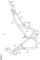
FIG. 2 is a side view showing a structure of a vehicle body frame of the two-wheeled hybrid vehicle; -
FIG. 3 is a perspective view showing the structure of the vehicle body frame; -
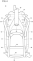
FIG. 4 is a front view showing the structure of the vehicle body frame; -
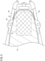
FIG. 5 is a plan view showing an example of an accommodating unit as viewed from above; -
FIG. 6 is a plan view showing an example of a power storage device that is installed in the accommodating unit as viewed from above; -
FIG. 7 is a perspective view showing a power storage device arrangement body that is fixed to front brackets and rear brackets; -
FIG. 8A is a perspective view illustrating an example of a vehicle body mounting stay; -
FIG. 8B is a side view showing a structure by which the vehicle body mounting stay is attached to a rear portion of an upper seat frame; -
FIG. 9 is a view showing the vehicle body mounting stay and a front cross frame as viewed from a rear side of the vehicle; -
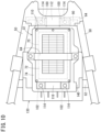
FIG. 10 is a plan view showing the power storage device and a tray that is fixed to a front cross frame and a rear cross frame as viewed from above; -
FIG. 11 is a vertical cross-sectional view of the power storage device and the tray that is fixed to the front cross frame and the rear cross frame; -
FIG. 12 is a plan view showing the power storage device arrangement body as viewed from above; and -
FIG. 13 is a perspective view showing the tray. - Hereinafter, an embodiment of a two-wheeled hybrid vehicle according to the present invention will be described with reference to
FIGS. 1 to 13 . - As shown in
FIG. 1 , the two-wheeled hybrid vehicle according to the present embodiment (hereinafter referred to as a vehicle 10) includes afront wheel 12, afront fork 14 supporting thefront wheel 12, avehicle body frame 16 supporting thefront fork 14 in a steerable manner (refer toFIGS. 2 to 4 ), and arear wheel 18 which is a drive wheel of thevehicle 10. - Further, the
vehicle 10 includes anengine 20, apower storage device 22, amotor 24 that drives therear wheel 18 with electrical power from thepower storage device 22, aseat 26 on which the vehicle occupant rides, and anaccommodating unit 28 formed below theseat 26. - As shown in
FIGS. 2 to 4 , the structure of thevehicle body frame 16 includes the following frames. - (a) A
head pipe 40 that supports the front fork 14 (seeFIG. 1 ) in a steerable manner. - (b) A pair of left and right
main frames 42 that branch to the right and left from an upper rear portion of thehead pipe 40, and extend in rearward and downward directions as viewed respectively from the side. - (c) A pair of left and right down frames 44 that branch to the right and left from a lower rear portion of the
head pipe 40, and extend in rearward and downward directions at a steeper slope than themain frames 42 as viewed respectively from the side. - (d) A
gusset 46 provided in between the left and right down frames 44 in the vicinity of thehead pipe 40. - (e) A pair of left and right
lower frames 48 that connect lower end portions of the left and right down frames 44 and rear end portions of the left and rightmain frames 42, respectively. - (f) A pair of left and right upper seat frames 50 that extend from middle portions of the left and right
main frames 42 to the rear portion of thevehicle 10 corresponding to theseat 26. - (g) A pair of left and right support frames 52 that extend from rear end portions of the left and right
lower frames 48 toward respective central portions of the left and right upper seat frames 50, and which support the left and right upper seat frames 50. - (h) Left and right lower seat frames 54 that extend from middle portions of the left and right support frames 52 to rear portions of the upper seat frames 50.
- (i) A
cross frame 56 connected between the left and right down frames 44. - (j) A
cross frame 58 having a curved shape and which is connected between lower portions of the left and right down frames 44. - (k) A
cross frame 60 connected between the left and right lower frames 48. - (l) A
front cross frame 62 connected between the left and right lower seat frames 54. - (m) A
rear cross frame 64 connected between rear portions of the left and right upper seat frames 50. - In the foregoing manner, taking into consideration the deflection of the
vehicle body frame 16 as a whole, and in order to increase rigidity, the frame structure of thevehicle 10 includes at least the pair of rearwardly extending left and rightmain frames 42, and the pair of downwardly extending left and right down frames 44. Further, by providing thegusset 46 in the vicinity of thehead pipe 40 of the left and right down frames 44, a space is formed for laying out the vehicle-mounted components. - In addition, as shown in
FIG. 1 , thepower storage device 22 of thevehicle 10 according to the present embodiment is disposed upwardly of therear wheel 18, and more rearward than adeepest portion 28a of theaccommodating unit 28. Furthermore, as shown inFIG. 5 , thepower storage device 22 is arranged in a manner so as to at least partially overlap with an upper open region Za of theaccommodating unit 28 as viewed from above. The region in which thepower storage device 22 is arranged is referred to as an "arrangement region Zb". - Further, as shown in
FIG. 6 , thepower storage device 22 includes a power storage device main body 70 (shown by the dashed line) constituted by stacking a plurality of power storage cells, acase 72 that covers the power storage devicemain body 70, and a power storagedevice arrangement body 74 by which thecase 72 is arranged in the arrangement region Zb in a state in which at least a portion of thecase 72 is covered. - As shown in
FIG. 7 , thecase 72 includes abox 80 having an upper surface opening and accommodating the power storage devicemain body 70 therein, and alid 82 that closes the opening of thebox 80. Thelid 82 is fixed to thebox 80, for example, using screws. - On the other hand, according to the present embodiment, the power storage
device arrangement body 74 includes side walls arranged in four directions, and further includes a tray shape having an upper surface opening. The case 72 (in which the power storage devicemain body 70 is accommodated) is mounted on a bottom portion of the tray-shaped power storagedevice arrangement body 74. Thecase 72 accommodated in the power storagedevice arrangement body 74 is prevented from moving upward, for example, by abelt 84 which is stretched over the power storagedevice arrangement body 74. Accordingly, thecase 72 is swingable together with the power storagedevice arrangement body 74 when thevehicle 10 vibrates. - Next, a description will be given with reference to
FIGS. 8A to 11 concerning a fixing structure for fixing the power storagedevice arrangement body 74 to the vehicle body. - As shown in
FIGS. 8A, 8B ,9 , and10 , such a fixing structure includes a vehicle body mounting stay 90 (seeFIGS. 8A and9 ), which is connected between the rear portions of the left and right upper seat frames 50 (seeFIG. 9 ), and is used for mounting the power storagedevice arrangement body 74 to the vehicle body, fixing tools 92 (for example, T-nuts or the like) provided at both end portions of the vehiclebody mounting stay 90, and mounting holes 94 (seeFIGS. 8B and9 ) provided in the rear portions of the left and right upper seat frames 50, and through which thefixing tools 92 are inserted. The vehiclebody mounting stay 90, for example, has a U-shape that is similar to the shape of thefront cross frame 62. - Accordingly, as shown in
FIGS. 8B and9 , thefixing tools 92 provided at both end portions of the vehiclebody mounting stay 90 are inserted respectively into the corresponding mountingholes 94, whereby the vehiclebody mounting stay 90 is attached in a bridging manner between the rear end portions of the left and right upper seat frames 50. In addition, from the rear side of thevehicle 10, for example, bolts are screwed (tightened) onto thefixing tools 92 that have been inserted through the mountingholes 94, thereby fixing the vehiclebody mounting stay 90 between the rear end portions of the upper seat frames 50. Consequently, the vehiclebody mounting stay 90 becomes disposed at the rear end portions of the upper seat frames 50 in parallel with thefront cross frame 62. The rear end portions of the upper seat frames 50 are positioned higher than thefront cross frame 62. Further, the upper seat frames 50 and the lower seat frames 54 are inclined upward toward the rearward direction, respectively. Since thepower storage device 22 is fixed along the upper seat frames 50 and the lower seat frames 54, thepower storage device 22 is also inclined upward toward the rearward direction. - As shown in
FIGS. 8A and9 , two inverted U-shaped vehicle body mounting brackets (hereinafter referred to as rear brackets 100) are mounted, for example, by welding, on the upper portion of the vehiclebody mounting stay 90, and as shown inFIG. 9 , two inverted U-shaped vehicle body mounting brackets (hereinafter, referred to as front brackets 102) are mounted, for example, by welding, on the upper portion of thefront cross frame 62. Screw holes 104 into which bolts are screwed are formed in the respective upper portions of therear brackets 100 and thefront brackets 102. Moreover, the height of therear brackets 100 is set to be higher than the height of thefront brackets 102. - On the other hand, as shown in
FIGS. 10 and11 , a fixingprotrusion 112 that extends in a rearward direction is provided on arear side wall 110 of the power storagedevice arrangement body 74. In the fixingprotrusion 112, through holes (not shown) are provided through whichbolts 114, which are screwed onto the rear brackets 100 (seeFIG. 9 ), are inserted. Further, astep 120 is formed at abottom portion 118 of the power storagedevice arrangement body 74 at a portion near to afront side wall 116, and through holes (not shown) through which the bolts 114 (seeFIG. 10 ) for being fixed to thefront brackets 102 are inserted are provided in anupper step portion 118a thereof. - Accordingly, as shown in
FIG. 10 , a connection site between the power storagedevice arrangement body 74 and therear brackets 100 overlaps (including a case of partial overlapping, as will apply in the same manner hereinafter) with therear cross frame 64 as viewed from above, and a connection site between the power storagedevice arrangement body 74 and thefront brackets 102 overlaps with thefront cross frame 62 as viewed from above. - Further, as shown in
FIG. 11 , a line La connecting thefront cross frame 62 and the vehiclebody mounting stay 90 is inclined downward toward the front of thevehicle 10 as viewed from the side, and further, since the height of therear brackets 100 is set to be higher than the height of the front brackets 102 (seeFIG. 9 ), thebottom portion 118 of the power storagedevice arrangement body 74 is also inclined downward toward the front of thevehicle 10. From such a positional relationship, as shown inFIG. 12 , within thebottom portion 118 of the power storagedevice arrangement body 74, a plurality (for example, four) drainage holes 122 (through holes) are formed at a location in the vicinity of thestep 120, and more specifically, in the vicinity of a lowermost inclined portion of the power storagedevice arrangement body 74. - Moreover, as shown in
FIG. 11 ,terminals 126 to which power cables 124 (seeFIGS. 6 and7 ) are connected are provided on the front side of thecase 72 in the longitudinal direction of thevehicle 10. More specifically, within thecase 72, theterminals 126 are provided at positions exposed to aspace 128 above theupper step portion 118a. Therefore, depending on the type of vehicle, thecase 72 may be accommodated in the power storagedevice arrangement body 74 in a state with thepower cables 124 connected to theterminals 126, or thepower cables 124 may be connected to theterminals 126 after thecase 72 has been accommodated in the power storagedevice arrangement body 74. In either situation, the assembly operation can be preformed efficiently in accordance with the type of vehicle. In addition, since the connection site (terminals 126) is provided on the front side of the power storage devicemain body 70, the high-voltage wiring can be reliably protected. - When mounting of the power storage
device arrangement body 74 is carried out, for example, the following assembly procedure is used. More specifically, at first, before attaching the vehiclebody mounting stay 90 to the rear portions of the upper seat frames 50, the rear portion of the power storagedevice arrangement body 74 is fixed to therear brackets 100 that are fixed to the vehiclebody mounting stay 90. Thereafter, the front portion of the power storagedevice arrangement body 74 is fixed to thefront brackets 102 that are fixed to thefront cross frame 62. Next, the vehiclebody mounting stay 90 is mounted on the rear portions of the upper seat frames 50. At this time, from the rear side of thevehicle 10, by the bolts being screwed (tightened) onto thefixing tools 92 that have been inserted through the mountingholes 94, the power storagedevice arrangement body 74 moves in a rearward direction together with the vehiclebody mounting stay 90, and at a stage at which screwing of the bolts is completed, the vehiclebody mounting stay 90 becomes fixed between the rear end portions of the upper seat frames 50, and the power storagedevice arrangement body 74 is positioned at a prescribed position. - In the example described above, although an example has been illustrated in which through holes through which the
bolts 114 are inserted are provided in the aforementionedupper step portion 118a of the power storagedevice arrangement body 74, instead of such an example, the lower surface of theupper step portion 118a and thefront brackets 102 may be welded, and the power storagedevice arrangement body 74 may be fixed without providing the through holes. In this case, since the front portion of the power storagedevice arrangement body 74 is firmly fixed to thefront brackets 102, there is no need to consider that thebolts 114 may become loosened during the fixing operation, and the efficiency of the assembly operation can be improved. - Further, as shown in
FIGS. 10 and11 , thevehicle 10 according to the present embodiment includes atray 130 that is positioned downwardly of the power storagedevice arrangement body 74, and which covers at least the front portion of the power storagedevice arrangement body 74. As shown inFIG. 13 , thetray 130 has abottom portion 132, and aperipheral wall 134 that is formed around thebottom portion 132. Thebottom portion 132 is formed in a manner so that a length L thereof in the longitudinal direction is longer than a length in the longitudinal direction of the power storagedevice arrangement body 74, and a width W of a front portion thereof is larger than a maximum width of the power storagedevice arrangement body 74. Further, astep 136 is formed on thetray 130 at a front part of thebottom portion 132. Afront bottom portion 138 extending from thestep 136 to the front end of thetray 130 is positioned at a downward location so as to be separated from the power storagedevice arrangement body 74. - Furthermore, on the
tray 130, front hooks 140 are integrally formed respectively on the left and right sides of thestep 136, and arear hook 142 is formed integrally in a central portion of a rear portion of thetray 130. The direction in which the front hooks 140 and therear hook 142 are bent is the same. Further, the distance between the pair of front hooks 140 is set to be wider than the installation width of thefront brackets 102. - In addition, in the case that the
tray 130 is attached, as shown inFIG. 10 , the front hooks 140 of thetray 130 are hooked onto thefront cross frame 62, and as shown inFIG. 11 , therear hook 142 of thetray 130 is hooked onto the vehiclebody mounting stay 90, whereby thetray 130 can be easily attached to the vehicle body. - In addition, the
tray 130, which is positioned below the power storagedevice arrangement body 74, swings together with the power storagedevice arrangement body 74. As a result, entry of foreign matter from below into the power storagedevice arrangement body 74 can be prevented. In the same manner as the power storagedevice arrangement body 74, thetray 130 is inclined in a downward direction toward the front of thevehicle 10. Accordingly, water from the power storagedevice arrangement body 74 can fall downward to a position that does not have an adverse influence on thevehicle 10. - In this manner, the
vehicle 10 according to the present embodiment is avehicle 10 that includes thefront wheel 12 , therear wheel 18, theengine 20, thepower storage device 22, themotor 24 that is driven by electrical power from thepower storage device 22, theseat 26, and theaccommodating unit 28 formed below theseat 26. In addition, thepower storage device 22 is disposed upwardly of therear wheel 18, and so as to at least partially overlap with the upper open region Za of theaccommodating unit 28 as viewed from above. - In accordance with such features, the upper portion of the
power storage device 22 can be covered by the upper portion of theaccommodating unit 28, and it is possible to prevent the vehicle occupant from accessing thepower storage device 22. More specifically, a configuration can be provided in which, while the high-voltage battery is reliably protected, user convenience such as the capacity of theaccommodating unit 28 or the like is not impaired. Further, since thepower storage device 22 is arranged below the opening of theaccommodating unit 28, the shape of theseat 26 can be designed without any concern given to the presence or absence of the power storage device 22 (high-voltage battery). Owing to this feature, components can be used in common between a vehicle having a high-voltage battery and a vehicle that does not have a high-voltage battery, thereby improving productivity. Further, because thepower storage device 22 is arranged at a high position, it is possible to prevent water from entering therein when thevehicle 10 is submerged. - In the present embodiment, the
power storage device 22 includes the power storage devicemain body 70 that is constituted by stacking a plurality of power storage cells, thecase 72 that covers the power storage devicemain body 70, and the power storagedevice arrangement body 74 by which thecase 72 is arranged in the arrangement region Zb in a state in which at least a portion of thecase 72 is covered. The power storagedevice arrangement body 74 is connected to the vehicle body mounting brackets (therear brackets 100 and the front brackets 102), and is fixed to the vehicle body via the vehicle body mounting brackets (100 and 102). - More specifically, the power storage
device arrangement body 74 arranges thecase 72 in the region (the arrangement region Zb) where thepower storage device 22 is disposed, in a state in which at least a portion of thecase 72 is covered. As a result, objects can be prevented from hitting against thepower storage device 22 from the exterior, and damage to thepower storage device 22 can be prevented. - In the present embodiment, the upper seat frames 50, and the
rear cross frame 64 that connects the rear portions of the upper seat frames 50 are further provided, and the connection site between the power storagedevice arrangement body 74 and the vehiclebody mounting brackets 100, and a position of therear cross frame 64 overlap as viewed from above. - More specifically, the
rear cross frame 64 is positioned at the rear portions of the upper seat frames 50. By the connection site between the power storagedevice arrangement body 74 and the vehiclebody mounting brackets 100 being made to overlap with therear cross frame 64 as viewed from above, thepower storage device 22 can be placed as near as possible to the rear side of the vehicle body. As a result, an effect is realized in that, for example, the capacity of theaccommodating unit 28 that is installed under theseat 26 can be assured, and the convenience of the vehicle occupant is not impaired. - In the present embodiment, the sites for fixing the vehicle
body mounting brackets 100 are constituted to be capable of being fastened from the rear side of thevehicle 10 through the mountingholes 94 that penetrate in the longitudinal direction of thevehicle 10. - In accordance with this feature, since the
power storage device 22 is disposed upwardly of therear wheel 18, and more rearward than thedeepest portion 28a of theaccommodating unit 28 so as to at least partially overlap with the upper open region Za of theaccommodating unit 28 as viewed from above, the ease of assembly can be improved. - In the present embodiment, the power storage
device arrangement body 74 including the power storage devicemain body 70 and thecase 72 is fixed so as to be inclined in the longitudinal direction of thevehicle 10, and the drainage holes 122 are formed in the vicinity of the lowermost inclined portion of the power storagedevice arrangement body 74. In accordance with this feature, it is possible to prevent the power storage devicemain body 70 and the case 72 (battery unit) from becoming submerged. - In the present embodiment, the
power cables 124 connected to thepower storage device 22 are further included, wherein thepower cables 124 are connected to a front side of thepower storage device 22 in the vehicle longitudinal direction. In accordance with this feature, since thepower cables 124 are disposed at a position where they are difficult to be accessed from the exterior, damage thereto can be prevented. - In the present embodiment, the
power storage device 22 is disposed upwardly of therear wheel 18, and more rearward than thedeepest portion 28a of theaccommodating unit 28, so as to at least partially overlap with the upper open region Za of theaccommodating unit 28 as viewed from above. In accordance with this feature, because the high-voltage battery is arranged at a high position, it is possible to prevent water from entering therein when thevehicle 10 is submerged. - Further, the
vehicle 10 according to the present embodiment is a two-wheeled hybrid vehicle (10) that includes thefront wheel 12 , therear wheel 18, theengine 20, thepower storage device 22, themotor 24 that is driven by electrical power from thepower storage device 22, theseat 26, and theaccommodating unit 28 formed below theseat 26. In addition, there are further included the upper seat frames 50, the lower seat frames 54, thefront cross frame 62 connected between the lower seat frames 54, therear cross frame 64 connected between the upper seat frames 50, the vehiclebody mounting stay 90 by which thepower storage device 22 is mounted on the vehicle body, and thefront brackets 102 by which thepower storage device 22 is mounted on thefront cross frame 62. The front portion of thepower storage device 22 is fixed directly to thefront cross frame 62 via thefront brackets 102, and the rear portion thereof is mounted on the vehicle body by way of bolt fastening via the vehiclebody mounting stay 90. - In accordance with this feature, since the rear portion of the
power storage device 22 is fastened by bolts, thepower storage device 22 can be configured in a swingable manner, the high-voltage wiring can be made to bend at the same time, and the high-voltage system can be reliably protected. - Although a description has been made with reference to preferred embodiments of the present invention, the technical scope of the present invention is not limited to the descriptive scope of the above-described embodiments. In the above-described embodiments, various modifications or improvements can be added thereto, as would be apparent to those skilled in the art. It is obvious from the statements of the claims that embodiments having such added modifications or improvements can be included within the technical scope of the present invention. Further, the parenthetical reference numerals referred to in the claims are provided in accordance with the reference numerals in the accompanying drawings in order to facilitate understanding of the present invention, but the present invention should not be construed as being limited to the elements denoted by such reference numerals.
Claims (5)
- A two-wheeled hybrid vehicle (10) comprising a front wheel (12), a rear wheel (18), an engine (20), a power storage device (22), a motor (24) configured to be driven by electrical power from the power storage device (22), a seat (26), and an accommodating unit (28) formed below the seat (26);wherein the power storage device (22) is disposed upwardly of the rear wheel (18) so as to at least partially overlap with an upper open region (Za) of the accommodating unit (28) as viewed from above,the power storage device (22) comprising:a power storage device main body (70) constituted by stacking a plurality of power storage cells;a case (72) configured to cover the power storage device main body (70); and a power storage device arrangement body (74) configured to arrange the case (72) in a region (Zb) where the power storage device (22) is disposed, in a state in which at least a portion of the case (72) is covered;wherein the power storage device arrangement body (74) is fixed to a vehicle body via a vehicle body mounting stay (90),the two-wheeled hybrid vehicle (10) further comprising:seat frames (50, 54); anda cross frame (64) configured to connect rear portions of the seat frames (50, 54), whereina connection site between the power storage device arrangement body (74) and a vehicle body mounting bracket (100), and a position of the cross frame (64) overlap as viewed from above,the power storage device (22) is disposed forwardly of the vehicle body mounting bracket (100),the two-wheeled hybrid vehicle (10) further comprises a power cable (124) connected to the power storage device (22), wherein the power cable (124) is connected to a front side of the power storage device (22) in a vehicle longitudinal direction,the case (72) includes a terminal (126) to which the power cable (124) is connected, wherein the terminal (126) is provided on a front side of the case (72) in the vehicle longitudinal direction, andthe motor (24) is provided further forward in the vehicle longitudinal direction than the terminal (126).
- The two-wheeled hybrid vehicle (10) according to claim 1, wherein the vehicle body mounting stay (90) is capable of being fastened from a rear side of the vehicle through a mounting hole (94) that penetrates in a longitudinal direction of the vehicle (10).
- The two-wheeled hybrid vehicle (10) according to claim 1 or 2, wherein:the power storage device arrangement body (74) including the power storage device main body (70) and the case (72) is fixed so as to be inclined in a vehicle longitudinal direction; anda drainage hole (122) is formed in the vicinity of a lowermost inclined portion of the power storage device arrangement body (74).
- The two-wheeled hybrid vehicle (10) according to any one of claims 1 to 3, wherein the power storage device (22) is disposed upwardly of the rear wheel (18), and more rearward than a deepest portion (28a) of the accommodating unit (28) so as to at least partially overlap with the upper open region (Za) of the accommodating unit (28) as viewed from above.
- The two-wheeled hybrid vehicle (10) according to claim 1, wherein the seat frames (50, 54) comprise upper seat frames (50) and lower seat frames (54), the two-wheeled hybrid vehicle further comprising a front cross frame (62) connected between the lower seat frames (54), a rear cross frame (64) connected between the upper seat frames (50); anda vehicle body mounting bracket (102) configured to mount the power storage device (22) on the front cross frame (62);wherein a front portion of the power storage device (22) is fixed directly to the front cross frame (62) via the vehicle body mounting bracket (102), and a rear portion thereof is mounted on the vehicle body by way of bolt fastening via the vehicle body mounting stay (90).
Applications Claiming Priority (2)
| Application Number | Priority Date | Filing Date | Title |
|---|---|---|---|
| JP2017192038 | 2017-09-29 | ||
| PCT/JP2018/034564 WO2019065390A1 (en) | 2017-09-29 | 2018-09-19 | Hybrid vehicle |
Publications (3)
| Publication Number | Publication Date |
|---|---|
| EP3689724A1 EP3689724A1 (en) | 2020-08-05 |
| EP3689724A4 EP3689724A4 (en) | 2020-10-28 |
| EP3689724B1 true EP3689724B1 (en) | 2023-06-07 |
Family
ID=65902405
Family Applications (1)
| Application Number | Title | Priority Date | Filing Date |
|---|---|---|---|
| EP18860600.8A Active EP3689724B1 (en) | 2017-09-29 | 2018-09-19 | Hybrid vehicle |
Country Status (4)
| Country | Link |
|---|---|
| EP (1) | EP3689724B1 (en) |
| JP (1) | JP6882501B2 (en) |
| CN (1) | CN111164006B (en) |
| WO (1) | WO2019065390A1 (en) |
Families Citing this family (2)
| Publication number | Priority date | Publication date | Assignee | Title |
|---|---|---|---|---|
| CN111688862A (en) * | 2020-06-30 | 2020-09-22 | 重庆安第斯摩托车制造有限公司 | Electric motorcycle |
| US12286188B2 (en) * | 2021-10-01 | 2025-04-29 | Kawasaki Motors, Ltd. | Saddle riding vehicle |
Family Cites Families (10)
| Publication number | Priority date | Publication date | Assignee | Title |
|---|---|---|---|---|
| JP2001119801A (en) * | 1999-10-19 | 2001-04-27 | Yamaha Motor Co Ltd | Control unit for electric vehicles |
| JP4041468B2 (en) | 2004-02-17 | 2008-01-30 | ヤマハ発動機株式会社 | Hybrid vehicle |
| JP2007008349A (en) * | 2005-06-30 | 2007-01-18 | Yamaha Motor Co Ltd | Hybrid vehicle |
| JP2007015641A (en) * | 2005-07-11 | 2007-01-25 | Yamaha Motor Co Ltd | Electric bicycle |
| JP5024811B2 (en) * | 2006-03-17 | 2012-09-12 | 国立大学法人静岡大学 | Electric vehicle power supply device |
| JP5513292B2 (en) * | 2010-07-20 | 2014-06-04 | 本田技研工業株式会社 | Saddle riding |
| JP5690147B2 (en) * | 2011-01-11 | 2015-03-25 | 本田技研工業株式会社 | Saddle riding vehicle |
| JP5680431B2 (en) * | 2011-02-02 | 2015-03-04 | 本田技研工業株式会社 | Motorcycle |
| JP6132628B2 (en) * | 2013-03-29 | 2017-05-24 | 本田技研工業株式会社 | Rear fender support structure for saddle-ride type vehicles |
| TWI629194B (en) * | 2016-01-22 | 2018-07-11 | 力能科技有限公司 | Battery electric vehicle |
-
2018
- 2018-09-19 JP JP2019544994A patent/JP6882501B2/en active Active
- 2018-09-19 CN CN201880063671.9A patent/CN111164006B/en active Active
- 2018-09-19 WO PCT/JP2018/034564 patent/WO2019065390A1/en not_active Ceased
- 2018-09-19 EP EP18860600.8A patent/EP3689724B1/en active Active
Also Published As
| Publication number | Publication date |
|---|---|
| CN111164006B (en) | 2021-10-01 |
| EP3689724A4 (en) | 2020-10-28 |
| CN111164006A (en) | 2020-05-15 |
| JP6882501B2 (en) | 2021-06-02 |
| JPWO2019065390A1 (en) | 2020-10-22 |
| WO2019065390A1 (en) | 2019-04-04 |
| EP3689724A1 (en) | 2020-08-05 |
Similar Documents
| Publication | Publication Date | Title |
|---|---|---|
| US11034248B2 (en) | Battery case fixing structure | |
| US12090831B2 (en) | Vehicle body lower structure | |
| EP2623406B1 (en) | Scooter-type electric vehicle | |
| US11034226B2 (en) | Vehicle | |
| JP7438481B2 (en) | Vehicle front structure | |
| JP7369681B2 (en) | Vehicles equipped with battery packs | |
| US7402918B2 (en) | Arrangement structure of electric junction box | |
| JP5656020B2 (en) | High-voltage cable routing structure for electric vehicles | |
| CN102555754B (en) | The Wiring harness arrangement structure of vehicle | |
| JP6722732B2 (en) | vehicle | |
| US20130119758A1 (en) | Mount structure to mount power controller on vehicle body | |
| JP6688851B2 (en) | vehicle | |
| CN103569267B (en) | Riding vehicle | |
| EP3689724B1 (en) | Hybrid vehicle | |
| JP7112371B2 (en) | drive unit | |
| JP2021112986A (en) | Mounting structure for power storage device | |
| JP5328441B2 (en) | Battery mounting structure for electric motorcycles | |
| JP7677841B2 (en) | Construction Machinery | |
| JP2012197019A (en) | Routing structure of high voltage cable | |
| JP2005247064A (en) | Power storage mechanism mounting structure | |
| JP7581794B2 (en) | Battery | |
| JP7627679B2 (en) | Battery pack | |
| JP2021066205A (en) | vehicle |
Legal Events
| Date | Code | Title | Description |
|---|---|---|---|
| STAA | Information on the status of an ep patent application or granted ep patent |
Free format text: STATUS: THE INTERNATIONAL PUBLICATION HAS BEEN MADE |
|
| PUAI | Public reference made under article 153(3) epc to a published international application that has entered the european phase |
Free format text: ORIGINAL CODE: 0009012 |
|
| STAA | Information on the status of an ep patent application or granted ep patent |
Free format text: STATUS: REQUEST FOR EXAMINATION WAS MADE |
|
| 17P | Request for examination filed |
Effective date: 20200427 |
|
| AK | Designated contracting states |
Kind code of ref document: A1 Designated state(s): AL AT BE BG CH CY CZ DE DK EE ES FI FR GB GR HR HU IE IS IT LI LT LU LV MC MK MT NL NO PL PT RO RS SE SI SK SM TR |
|
| AX | Request for extension of the european patent |
Extension state: BA ME |
|
| A4 | Supplementary search report drawn up and despatched |
Effective date: 20200929 |
|
| RIC1 | Information provided on ipc code assigned before grant |
Ipc: B62K 11/10 20060101ALI20200923BHEP Ipc: B62J 9/00 20200101AFI20200923BHEP Ipc: B62J 43/16 20200101ALI20200923BHEP Ipc: B62J 11/00 20200101ALI20200923BHEP Ipc: B60K 1/04 20190101ALI20200923BHEP Ipc: B62K 11/04 20060101ALI20200923BHEP Ipc: B60K 6/40 20071001ALI20200923BHEP |
|
| DAV | Request for validation of the european patent (deleted) | ||
| DAX | Request for extension of the european patent (deleted) | ||
| STAA | Information on the status of an ep patent application or granted ep patent |
Free format text: STATUS: EXAMINATION IS IN PROGRESS |
|
| 17Q | First examination report despatched |
Effective date: 20210527 |
|
| RIC1 | Information provided on ipc code assigned before grant |
Ipc: B62J 9/14 20200101ALI20220513BHEP Ipc: B60K 1/04 20190101ALI20220513BHEP Ipc: B60K 6/40 20071001ALI20220513BHEP Ipc: B62J 11/00 20200101ALI20220513BHEP Ipc: B62K 11/10 20060101ALI20220513BHEP Ipc: B62J 43/16 20200101ALI20220513BHEP Ipc: B62K 11/04 20060101ALI20220513BHEP Ipc: B62J 9/00 20200101AFI20220513BHEP |
|
| GRAP | Despatch of communication of intention to grant a patent |
Free format text: ORIGINAL CODE: EPIDOSNIGR1 |
|
| STAA | Information on the status of an ep patent application or granted ep patent |
Free format text: STATUS: GRANT OF PATENT IS INTENDED |
|
| INTG | Intention to grant announced |
Effective date: 20220729 |
|
| GRAJ | Information related to disapproval of communication of intention to grant by the applicant or resumption of examination proceedings by the epo deleted |
Free format text: ORIGINAL CODE: EPIDOSDIGR1 |
|
| STAA | Information on the status of an ep patent application or granted ep patent |
Free format text: STATUS: EXAMINATION IS IN PROGRESS |
|
| GRAP | Despatch of communication of intention to grant a patent |
Free format text: ORIGINAL CODE: EPIDOSNIGR1 |
|
| STAA | Information on the status of an ep patent application or granted ep patent |
Free format text: STATUS: GRANT OF PATENT IS INTENDED |
|
| INTC | Intention to grant announced (deleted) | ||
| INTG | Intention to grant announced |
Effective date: 20230104 |
|
| GRAS | Grant fee paid |
Free format text: ORIGINAL CODE: EPIDOSNIGR3 |
|
| GRAA | (expected) grant |
Free format text: ORIGINAL CODE: 0009210 |
|
| STAA | Information on the status of an ep patent application or granted ep patent |
Free format text: STATUS: THE PATENT HAS BEEN GRANTED |
|
| AK | Designated contracting states |
Kind code of ref document: B1 Designated state(s): AL AT BE BG CH CY CZ DE DK EE ES FI FR GB GR HR HU IE IS IT LI LT LU LV MC MK MT NL NO PL PT RO RS SE SI SK SM TR |
|
| REG | Reference to a national code |
Ref country code: GB Ref legal event code: FG4D |
|
| REG | Reference to a national code |
Ref country code: CH Ref legal event code: EP Ref country code: AT Ref legal event code: REF Ref document number: 1574203 Country of ref document: AT Kind code of ref document: T Effective date: 20230615 |
|
| REG | Reference to a national code |
Ref country code: DE Ref legal event code: R096 Ref document number: 602018051560 Country of ref document: DE |
|
| REG | Reference to a national code |
Ref country code: LT Ref legal event code: MG9D |
|
| REG | Reference to a national code |
Ref country code: NL Ref legal event code: MP Effective date: 20230607 |
|
| PG25 | Lapsed in a contracting state [announced via postgrant information from national office to epo] |
Ref country code: SE Free format text: LAPSE BECAUSE OF FAILURE TO SUBMIT A TRANSLATION OF THE DESCRIPTION OR TO PAY THE FEE WITHIN THE PRESCRIBED TIME-LIMIT Effective date: 20230607 Ref country code: NO Free format text: LAPSE BECAUSE OF FAILURE TO SUBMIT A TRANSLATION OF THE DESCRIPTION OR TO PAY THE FEE WITHIN THE PRESCRIBED TIME-LIMIT Effective date: 20230907 Ref country code: ES Free format text: LAPSE BECAUSE OF FAILURE TO SUBMIT A TRANSLATION OF THE DESCRIPTION OR TO PAY THE FEE WITHIN THE PRESCRIBED TIME-LIMIT Effective date: 20230607 |
|
| REG | Reference to a national code |
Ref country code: AT Ref legal event code: MK05 Ref document number: 1574203 Country of ref document: AT Kind code of ref document: T Effective date: 20230607 |
|
| PG25 | Lapsed in a contracting state [announced via postgrant information from national office to epo] |
Ref country code: RS Free format text: LAPSE BECAUSE OF FAILURE TO SUBMIT A TRANSLATION OF THE DESCRIPTION OR TO PAY THE FEE WITHIN THE PRESCRIBED TIME-LIMIT Effective date: 20230607 Ref country code: NL Free format text: LAPSE BECAUSE OF FAILURE TO SUBMIT A TRANSLATION OF THE DESCRIPTION OR TO PAY THE FEE WITHIN THE PRESCRIBED TIME-LIMIT Effective date: 20230607 Ref country code: LV Free format text: LAPSE BECAUSE OF FAILURE TO SUBMIT A TRANSLATION OF THE DESCRIPTION OR TO PAY THE FEE WITHIN THE PRESCRIBED TIME-LIMIT Effective date: 20230607 Ref country code: LT Free format text: LAPSE BECAUSE OF FAILURE TO SUBMIT A TRANSLATION OF THE DESCRIPTION OR TO PAY THE FEE WITHIN THE PRESCRIBED TIME-LIMIT Effective date: 20230607 Ref country code: HR Free format text: LAPSE BECAUSE OF FAILURE TO SUBMIT A TRANSLATION OF THE DESCRIPTION OR TO PAY THE FEE WITHIN THE PRESCRIBED TIME-LIMIT Effective date: 20230607 Ref country code: GR Free format text: LAPSE BECAUSE OF FAILURE TO SUBMIT A TRANSLATION OF THE DESCRIPTION OR TO PAY THE FEE WITHIN THE PRESCRIBED TIME-LIMIT Effective date: 20230908 |
|
| PG25 | Lapsed in a contracting state [announced via postgrant information from national office to epo] |
Ref country code: FI Free format text: LAPSE BECAUSE OF FAILURE TO SUBMIT A TRANSLATION OF THE DESCRIPTION OR TO PAY THE FEE WITHIN THE PRESCRIBED TIME-LIMIT Effective date: 20230607 |
|
| PG25 | Lapsed in a contracting state [announced via postgrant information from national office to epo] |
Ref country code: SK Free format text: LAPSE BECAUSE OF FAILURE TO SUBMIT A TRANSLATION OF THE DESCRIPTION OR TO PAY THE FEE WITHIN THE PRESCRIBED TIME-LIMIT Effective date: 20230607 |
|
| PG25 | Lapsed in a contracting state [announced via postgrant information from national office to epo] |
Ref country code: IS Free format text: LAPSE BECAUSE OF FAILURE TO SUBMIT A TRANSLATION OF THE DESCRIPTION OR TO PAY THE FEE WITHIN THE PRESCRIBED TIME-LIMIT Effective date: 20231007 |
|
| PG25 | Lapsed in a contracting state [announced via postgrant information from national office to epo] |
Ref country code: SM Free format text: LAPSE BECAUSE OF FAILURE TO SUBMIT A TRANSLATION OF THE DESCRIPTION OR TO PAY THE FEE WITHIN THE PRESCRIBED TIME-LIMIT Effective date: 20230607 Ref country code: SK Free format text: LAPSE BECAUSE OF FAILURE TO SUBMIT A TRANSLATION OF THE DESCRIPTION OR TO PAY THE FEE WITHIN THE PRESCRIBED TIME-LIMIT Effective date: 20230607 Ref country code: RO Free format text: LAPSE BECAUSE OF FAILURE TO SUBMIT A TRANSLATION OF THE DESCRIPTION OR TO PAY THE FEE WITHIN THE PRESCRIBED TIME-LIMIT Effective date: 20230607 Ref country code: PT Free format text: LAPSE BECAUSE OF FAILURE TO SUBMIT A TRANSLATION OF THE DESCRIPTION OR TO PAY THE FEE WITHIN THE PRESCRIBED TIME-LIMIT Effective date: 20231009 Ref country code: IS Free format text: LAPSE BECAUSE OF FAILURE TO SUBMIT A TRANSLATION OF THE DESCRIPTION OR TO PAY THE FEE WITHIN THE PRESCRIBED TIME-LIMIT Effective date: 20231007 Ref country code: EE Free format text: LAPSE BECAUSE OF FAILURE TO SUBMIT A TRANSLATION OF THE DESCRIPTION OR TO PAY THE FEE WITHIN THE PRESCRIBED TIME-LIMIT Effective date: 20230607 Ref country code: CZ Free format text: LAPSE BECAUSE OF FAILURE TO SUBMIT A TRANSLATION OF THE DESCRIPTION OR TO PAY THE FEE WITHIN THE PRESCRIBED TIME-LIMIT Effective date: 20230607 Ref country code: AT Free format text: LAPSE BECAUSE OF FAILURE TO SUBMIT A TRANSLATION OF THE DESCRIPTION OR TO PAY THE FEE WITHIN THE PRESCRIBED TIME-LIMIT Effective date: 20230607 |
|
| PG25 | Lapsed in a contracting state [announced via postgrant information from national office to epo] |
Ref country code: PL Free format text: LAPSE BECAUSE OF FAILURE TO SUBMIT A TRANSLATION OF THE DESCRIPTION OR TO PAY THE FEE WITHIN THE PRESCRIBED TIME-LIMIT Effective date: 20230607 |
|
| REG | Reference to a national code |
Ref country code: DE Ref legal event code: R097 Ref document number: 602018051560 Country of ref document: DE |
|
| PLBE | No opposition filed within time limit |
Free format text: ORIGINAL CODE: 0009261 |
|
| STAA | Information on the status of an ep patent application or granted ep patent |
Free format text: STATUS: NO OPPOSITION FILED WITHIN TIME LIMIT |
|
| PG25 | Lapsed in a contracting state [announced via postgrant information from national office to epo] |
Ref country code: DK Free format text: LAPSE BECAUSE OF FAILURE TO SUBMIT A TRANSLATION OF THE DESCRIPTION OR TO PAY THE FEE WITHIN THE PRESCRIBED TIME-LIMIT Effective date: 20230607 |
|
| REG | Reference to a national code |
Ref country code: CH Ref legal event code: PL |
|
| PG25 | Lapsed in a contracting state [announced via postgrant information from national office to epo] |
Ref country code: SI Free format text: LAPSE BECAUSE OF FAILURE TO SUBMIT A TRANSLATION OF THE DESCRIPTION OR TO PAY THE FEE WITHIN THE PRESCRIBED TIME-LIMIT Effective date: 20230607 |
|
| 26N | No opposition filed |
Effective date: 20240308 |
|
| PG25 | Lapsed in a contracting state [announced via postgrant information from national office to epo] |
Ref country code: LU Free format text: LAPSE BECAUSE OF NON-PAYMENT OF DUE FEES Effective date: 20230919 |
|
| REG | Reference to a national code |
Ref country code: BE Ref legal event code: MM Effective date: 20230930 |
|
| GBPC | Gb: european patent ceased through non-payment of renewal fee |
Effective date: 20230919 |
|
| PG25 | Lapsed in a contracting state [announced via postgrant information from national office to epo] |
Ref country code: LU Free format text: LAPSE BECAUSE OF NON-PAYMENT OF DUE FEES Effective date: 20230919 Ref country code: MC Free format text: LAPSE BECAUSE OF FAILURE TO SUBMIT A TRANSLATION OF THE DESCRIPTION OR TO PAY THE FEE WITHIN THE PRESCRIBED TIME-LIMIT Effective date: 20230607 Ref country code: SI Free format text: LAPSE BECAUSE OF FAILURE TO SUBMIT A TRANSLATION OF THE DESCRIPTION OR TO PAY THE FEE WITHIN THE PRESCRIBED TIME-LIMIT Effective date: 20230607 Ref country code: IT Free format text: LAPSE BECAUSE OF FAILURE TO SUBMIT A TRANSLATION OF THE DESCRIPTION OR TO PAY THE FEE WITHIN THE PRESCRIBED TIME-LIMIT Effective date: 20230607 |
|
| REG | Reference to a national code |
Ref country code: IE Ref legal event code: MM4A |
|
| PG25 | Lapsed in a contracting state [announced via postgrant information from national office to epo] |
Ref country code: IE Free format text: LAPSE BECAUSE OF NON-PAYMENT OF DUE FEES Effective date: 20230919 |
|
| PG25 | Lapsed in a contracting state [announced via postgrant information from national office to epo] |
Ref country code: GB Free format text: LAPSE BECAUSE OF NON-PAYMENT OF DUE FEES Effective date: 20230919 |
|
| PG25 | Lapsed in a contracting state [announced via postgrant information from national office to epo] |
Ref country code: CH Free format text: LAPSE BECAUSE OF NON-PAYMENT OF DUE FEES Effective date: 20230930 |
|
| PG25 | Lapsed in a contracting state [announced via postgrant information from national office to epo] |
Ref country code: IE Free format text: LAPSE BECAUSE OF NON-PAYMENT OF DUE FEES Effective date: 20230919 Ref country code: GB Free format text: LAPSE BECAUSE OF NON-PAYMENT OF DUE FEES Effective date: 20230919 Ref country code: FR Free format text: LAPSE BECAUSE OF NON-PAYMENT OF DUE FEES Effective date: 20230930 Ref country code: CH Free format text: LAPSE BECAUSE OF NON-PAYMENT OF DUE FEES Effective date: 20230930 |
|
| PG25 | Lapsed in a contracting state [announced via postgrant information from national office to epo] |
Ref country code: BE Free format text: LAPSE BECAUSE OF NON-PAYMENT OF DUE FEES Effective date: 20230930 |
|
| REG | Reference to a national code |
Ref country code: DE Ref legal event code: R084 Ref document number: 602018051560 Country of ref document: DE |
|
| PG25 | Lapsed in a contracting state [announced via postgrant information from national office to epo] |
Ref country code: BG Free format text: LAPSE BECAUSE OF FAILURE TO SUBMIT A TRANSLATION OF THE DESCRIPTION OR TO PAY THE FEE WITHIN THE PRESCRIBED TIME-LIMIT Effective date: 20230607 |
|
| PG25 | Lapsed in a contracting state [announced via postgrant information from national office to epo] |
Ref country code: BG Free format text: LAPSE BECAUSE OF FAILURE TO SUBMIT A TRANSLATION OF THE DESCRIPTION OR TO PAY THE FEE WITHIN THE PRESCRIBED TIME-LIMIT Effective date: 20230607 |
|
| PG25 | Lapsed in a contracting state [announced via postgrant information from national office to epo] |
Ref country code: CY Free format text: LAPSE BECAUSE OF FAILURE TO SUBMIT A TRANSLATION OF THE DESCRIPTION OR TO PAY THE FEE WITHIN THE PRESCRIBED TIME-LIMIT; INVALID AB INITIO Effective date: 20180919 |
|
| PG25 | Lapsed in a contracting state [announced via postgrant information from national office to epo] |
Ref country code: HU Free format text: LAPSE BECAUSE OF FAILURE TO SUBMIT A TRANSLATION OF THE DESCRIPTION OR TO PAY THE FEE WITHIN THE PRESCRIBED TIME-LIMIT; INVALID AB INITIO Effective date: 20180919 |
|
| PGFP | Annual fee paid to national office [announced via postgrant information from national office to epo] |
Ref country code: DE Payment date: 20250820 Year of fee payment: 8 |
|
| PG25 | Lapsed in a contracting state [announced via postgrant information from national office to epo] |
Ref country code: TR Free format text: LAPSE BECAUSE OF FAILURE TO SUBMIT A TRANSLATION OF THE DESCRIPTION OR TO PAY THE FEE WITHIN THE PRESCRIBED TIME-LIMIT Effective date: 20230607 |