EP3689657A1 - Hybrid vehicle and power system thereof - Google Patents
Hybrid vehicle and power system thereof Download PDFInfo
- Publication number
- EP3689657A1 EP3689657A1 EP18863007.3A EP18863007A EP3689657A1 EP 3689657 A1 EP3689657 A1 EP 3689657A1 EP 18863007 A EP18863007 A EP 18863007A EP 3689657 A1 EP3689657 A1 EP 3689657A1
- Authority
- EP
- European Patent Office
- Prior art keywords
- voltage
- power
- auxiliary motor
- converter
- voltage stabilizing
- Prior art date
- Legal status (The legal status is an assumption and is not a legal conclusion. Google has not performed a legal analysis and makes no representation as to the accuracy of the status listed.)
- Granted
Links
Images




Classifications
-
- B—PERFORMING OPERATIONS; TRANSPORTING
- B60—VEHICLES IN GENERAL
- B60K—ARRANGEMENT OR MOUNTING OF PROPULSION UNITS OR OF TRANSMISSIONS IN VEHICLES; ARRANGEMENT OR MOUNTING OF PLURAL DIVERSE PRIME-MOVERS IN VEHICLES; AUXILIARY DRIVES FOR VEHICLES; INSTRUMENTATION OR DASHBOARDS FOR VEHICLES; ARRANGEMENTS IN CONNECTION WITH COOLING, AIR INTAKE, GAS EXHAUST OR FUEL SUPPLY OF PROPULSION UNITS IN VEHICLES
- B60K6/00—Arrangement or mounting of plural diverse prime-movers for mutual or common propulsion, e.g. hybrid propulsion systems comprising electric motors and internal combustion engines
- B60K6/20—Arrangement or mounting of plural diverse prime-movers for mutual or common propulsion, e.g. hybrid propulsion systems comprising electric motors and internal combustion engines the prime-movers consisting of electric motors and internal combustion engines, e.g. HEVs
- B60K6/42—Arrangement or mounting of plural diverse prime-movers for mutual or common propulsion, e.g. hybrid propulsion systems comprising electric motors and internal combustion engines the prime-movers consisting of electric motors and internal combustion engines, e.g. HEVs characterised by the architecture of the hybrid electric vehicle
- B60K6/48—Parallel type
-
- B—PERFORMING OPERATIONS; TRANSPORTING
- B60—VEHICLES IN GENERAL
- B60K—ARRANGEMENT OR MOUNTING OF PROPULSION UNITS OR OF TRANSMISSIONS IN VEHICLES; ARRANGEMENT OR MOUNTING OF PLURAL DIVERSE PRIME-MOVERS IN VEHICLES; AUXILIARY DRIVES FOR VEHICLES; INSTRUMENTATION OR DASHBOARDS FOR VEHICLES; ARRANGEMENTS IN CONNECTION WITH COOLING, AIR INTAKE, GAS EXHAUST OR FUEL SUPPLY OF PROPULSION UNITS IN VEHICLES
- B60K6/00—Arrangement or mounting of plural diverse prime-movers for mutual or common propulsion, e.g. hybrid propulsion systems comprising electric motors and internal combustion engines
- B60K6/20—Arrangement or mounting of plural diverse prime-movers for mutual or common propulsion, e.g. hybrid propulsion systems comprising electric motors and internal combustion engines the prime-movers consisting of electric motors and internal combustion engines, e.g. HEVs
- B60K6/42—Arrangement or mounting of plural diverse prime-movers for mutual or common propulsion, e.g. hybrid propulsion systems comprising electric motors and internal combustion engines the prime-movers consisting of electric motors and internal combustion engines, e.g. HEVs characterised by the architecture of the hybrid electric vehicle
- B60K6/44—Series-parallel type
-
- B—PERFORMING OPERATIONS; TRANSPORTING
- B60—VEHICLES IN GENERAL
- B60K—ARRANGEMENT OR MOUNTING OF PROPULSION UNITS OR OF TRANSMISSIONS IN VEHICLES; ARRANGEMENT OR MOUNTING OF PLURAL DIVERSE PRIME-MOVERS IN VEHICLES; AUXILIARY DRIVES FOR VEHICLES; INSTRUMENTATION OR DASHBOARDS FOR VEHICLES; ARRANGEMENTS IN CONNECTION WITH COOLING, AIR INTAKE, GAS EXHAUST OR FUEL SUPPLY OF PROPULSION UNITS IN VEHICLES
- B60K6/00—Arrangement or mounting of plural diverse prime-movers for mutual or common propulsion, e.g. hybrid propulsion systems comprising electric motors and internal combustion engines
- B60K6/20—Arrangement or mounting of plural diverse prime-movers for mutual or common propulsion, e.g. hybrid propulsion systems comprising electric motors and internal combustion engines the prime-movers consisting of electric motors and internal combustion engines, e.g. HEVs
- B60K6/42—Arrangement or mounting of plural diverse prime-movers for mutual or common propulsion, e.g. hybrid propulsion systems comprising electric motors and internal combustion engines the prime-movers consisting of electric motors and internal combustion engines, e.g. HEVs characterised by the architecture of the hybrid electric vehicle
- B60K6/44—Series-parallel type
- B60K6/448—Electrical distribution type
-
- B—PERFORMING OPERATIONS; TRANSPORTING
- B60—VEHICLES IN GENERAL
- B60K—ARRANGEMENT OR MOUNTING OF PROPULSION UNITS OR OF TRANSMISSIONS IN VEHICLES; ARRANGEMENT OR MOUNTING OF PLURAL DIVERSE PRIME-MOVERS IN VEHICLES; AUXILIARY DRIVES FOR VEHICLES; INSTRUMENTATION OR DASHBOARDS FOR VEHICLES; ARRANGEMENTS IN CONNECTION WITH COOLING, AIR INTAKE, GAS EXHAUST OR FUEL SUPPLY OF PROPULSION UNITS IN VEHICLES
- B60K6/00—Arrangement or mounting of plural diverse prime-movers for mutual or common propulsion, e.g. hybrid propulsion systems comprising electric motors and internal combustion engines
- B60K6/20—Arrangement or mounting of plural diverse prime-movers for mutual or common propulsion, e.g. hybrid propulsion systems comprising electric motors and internal combustion engines the prime-movers consisting of electric motors and internal combustion engines, e.g. HEVs
- B60K6/50—Architecture of the driveline characterised by arrangement or kind of transmission units
- B60K6/52—Driving a plurality of drive axles, e.g. four-wheel drive
-
- B—PERFORMING OPERATIONS; TRANSPORTING
- B60—VEHICLES IN GENERAL
- B60L—PROPULSION OF ELECTRICALLY-PROPELLED VEHICLES; SUPPLYING ELECTRIC POWER FOR AUXILIARY EQUIPMENT OF ELECTRICALLY-PROPELLED VEHICLES; ELECTRODYNAMIC BRAKE SYSTEMS FOR VEHICLES IN GENERAL; MAGNETIC SUSPENSION OR LEVITATION FOR VEHICLES; MONITORING OPERATING VARIABLES OF ELECTRICALLY-PROPELLED VEHICLES; ELECTRIC SAFETY DEVICES FOR ELECTRICALLY-PROPELLED VEHICLES
- B60L3/00—Electric devices on electrically-propelled vehicles for safety purposes; Monitoring operating variables, e.g. speed, deceleration or energy consumption
- B60L3/0023—Detecting, eliminating, remedying or compensating for drive train abnormalities, e.g. failures within the drive train
- B60L3/0046—Detecting, eliminating, remedying or compensating for drive train abnormalities, e.g. failures within the drive train relating to electric energy storage systems, e.g. batteries or capacitors
-
- B—PERFORMING OPERATIONS; TRANSPORTING
- B60—VEHICLES IN GENERAL
- B60L—PROPULSION OF ELECTRICALLY-PROPELLED VEHICLES; SUPPLYING ELECTRIC POWER FOR AUXILIARY EQUIPMENT OF ELECTRICALLY-PROPELLED VEHICLES; ELECTRODYNAMIC BRAKE SYSTEMS FOR VEHICLES IN GENERAL; MAGNETIC SUSPENSION OR LEVITATION FOR VEHICLES; MONITORING OPERATING VARIABLES OF ELECTRICALLY-PROPELLED VEHICLES; ELECTRIC SAFETY DEVICES FOR ELECTRICALLY-PROPELLED VEHICLES
- B60L3/00—Electric devices on electrically-propelled vehicles for safety purposes; Monitoring operating variables, e.g. speed, deceleration or energy consumption
- B60L3/0023—Detecting, eliminating, remedying or compensating for drive train abnormalities, e.g. failures within the drive train
- B60L3/0084—Detecting, eliminating, remedying or compensating for drive train abnormalities, e.g. failures within the drive train relating to control modules
-
- B—PERFORMING OPERATIONS; TRANSPORTING
- B60—VEHICLES IN GENERAL
- B60L—PROPULSION OF ELECTRICALLY-PROPELLED VEHICLES; SUPPLYING ELECTRIC POWER FOR AUXILIARY EQUIPMENT OF ELECTRICALLY-PROPELLED VEHICLES; ELECTRODYNAMIC BRAKE SYSTEMS FOR VEHICLES IN GENERAL; MAGNETIC SUSPENSION OR LEVITATION FOR VEHICLES; MONITORING OPERATING VARIABLES OF ELECTRICALLY-PROPELLED VEHICLES; ELECTRIC SAFETY DEVICES FOR ELECTRICALLY-PROPELLED VEHICLES
- B60L50/00—Electric propulsion with power supplied within the vehicle
- B60L50/10—Electric propulsion with power supplied within the vehicle using propulsion power supplied by engine-driven generators, e.g. generators driven by combustion engines
- B60L50/16—Electric propulsion with power supplied within the vehicle using propulsion power supplied by engine-driven generators, e.g. generators driven by combustion engines with provision for separate direct mechanical propulsion
-
- B—PERFORMING OPERATIONS; TRANSPORTING
- B60—VEHICLES IN GENERAL
- B60L—PROPULSION OF ELECTRICALLY-PROPELLED VEHICLES; SUPPLYING ELECTRIC POWER FOR AUXILIARY EQUIPMENT OF ELECTRICALLY-PROPELLED VEHICLES; ELECTRODYNAMIC BRAKE SYSTEMS FOR VEHICLES IN GENERAL; MAGNETIC SUSPENSION OR LEVITATION FOR VEHICLES; MONITORING OPERATING VARIABLES OF ELECTRICALLY-PROPELLED VEHICLES; ELECTRIC SAFETY DEVICES FOR ELECTRICALLY-PROPELLED VEHICLES
- B60L50/00—Electric propulsion with power supplied within the vehicle
- B60L50/50—Electric propulsion with power supplied within the vehicle using propulsion power supplied by batteries or fuel cells
- B60L50/60—Electric propulsion with power supplied within the vehicle using propulsion power supplied by batteries or fuel cells using power supplied by batteries
-
- B—PERFORMING OPERATIONS; TRANSPORTING
- B60—VEHICLES IN GENERAL
- B60W—CONJOINT CONTROL OF VEHICLE SUB-UNITS OF DIFFERENT TYPE OR DIFFERENT FUNCTION; CONTROL SYSTEMS SPECIALLY ADAPTED FOR HYBRID VEHICLES; ROAD VEHICLE DRIVE CONTROL SYSTEMS FOR PURPOSES NOT RELATED TO THE CONTROL OF A PARTICULAR SUB-UNIT
- B60W20/00—Control systems specially adapted for hybrid vehicles
- B60W20/50—Control strategies for responding to system failures, e.g. for fault diagnosis, failsafe operation or limp mode
-
- B—PERFORMING OPERATIONS; TRANSPORTING
- B60—VEHICLES IN GENERAL
- B60W—CONJOINT CONTROL OF VEHICLE SUB-UNITS OF DIFFERENT TYPE OR DIFFERENT FUNCTION; CONTROL SYSTEMS SPECIALLY ADAPTED FOR HYBRID VEHICLES; ROAD VEHICLE DRIVE CONTROL SYSTEMS FOR PURPOSES NOT RELATED TO THE CONTROL OF A PARTICULAR SUB-UNIT
- B60W50/00—Details of control systems for road vehicle drive control not related to the control of a particular sub-unit, e.g. process diagnostic or vehicle driver interfaces
- B60W50/02—Ensuring safety in case of control system failures, e.g. by diagnosing, circumventing or fixing failures
- B60W50/0205—Diagnosing or detecting failures; Failure detection models
-
- B—PERFORMING OPERATIONS; TRANSPORTING
- B60—VEHICLES IN GENERAL
- B60W—CONJOINT CONTROL OF VEHICLE SUB-UNITS OF DIFFERENT TYPE OR DIFFERENT FUNCTION; CONTROL SYSTEMS SPECIALLY ADAPTED FOR HYBRID VEHICLES; ROAD VEHICLE DRIVE CONTROL SYSTEMS FOR PURPOSES NOT RELATED TO THE CONTROL OF A PARTICULAR SUB-UNIT
- B60W50/00—Details of control systems for road vehicle drive control not related to the control of a particular sub-unit, e.g. process diagnostic or vehicle driver interfaces
- B60W50/02—Ensuring safety in case of control system failures, e.g. by diagnosing, circumventing or fixing failures
- B60W50/029—Adapting to failures or work around with other constraints, e.g. circumvention by avoiding use of failed parts
-
- B—PERFORMING OPERATIONS; TRANSPORTING
- B60—VEHICLES IN GENERAL
- B60L—PROPULSION OF ELECTRICALLY-PROPELLED VEHICLES; SUPPLYING ELECTRIC POWER FOR AUXILIARY EQUIPMENT OF ELECTRICALLY-PROPELLED VEHICLES; ELECTRODYNAMIC BRAKE SYSTEMS FOR VEHICLES IN GENERAL; MAGNETIC SUSPENSION OR LEVITATION FOR VEHICLES; MONITORING OPERATING VARIABLES OF ELECTRICALLY-PROPELLED VEHICLES; ELECTRIC SAFETY DEVICES FOR ELECTRICALLY-PROPELLED VEHICLES
- B60L2210/00—Converter types
- B60L2210/10—DC to DC converters
-
- B—PERFORMING OPERATIONS; TRANSPORTING
- B60—VEHICLES IN GENERAL
- B60L—PROPULSION OF ELECTRICALLY-PROPELLED VEHICLES; SUPPLYING ELECTRIC POWER FOR AUXILIARY EQUIPMENT OF ELECTRICALLY-PROPELLED VEHICLES; ELECTRODYNAMIC BRAKE SYSTEMS FOR VEHICLES IN GENERAL; MAGNETIC SUSPENSION OR LEVITATION FOR VEHICLES; MONITORING OPERATING VARIABLES OF ELECTRICALLY-PROPELLED VEHICLES; ELECTRIC SAFETY DEVICES FOR ELECTRICALLY-PROPELLED VEHICLES
- B60L2220/00—Electrical machine types; Structures or applications thereof
- B60L2220/40—Electrical machine applications
- B60L2220/42—Electrical machine applications with use of more than one motor
-
- B—PERFORMING OPERATIONS; TRANSPORTING
- B60—VEHICLES IN GENERAL
- B60L—PROPULSION OF ELECTRICALLY-PROPELLED VEHICLES; SUPPLYING ELECTRIC POWER FOR AUXILIARY EQUIPMENT OF ELECTRICALLY-PROPELLED VEHICLES; ELECTRODYNAMIC BRAKE SYSTEMS FOR VEHICLES IN GENERAL; MAGNETIC SUSPENSION OR LEVITATION FOR VEHICLES; MONITORING OPERATING VARIABLES OF ELECTRICALLY-PROPELLED VEHICLES; ELECTRIC SAFETY DEVICES FOR ELECTRICALLY-PROPELLED VEHICLES
- B60L2240/00—Control parameters of input or output; Target parameters
- B60L2240/40—Drive Train control parameters
- B60L2240/52—Drive Train control parameters related to converters
- B60L2240/527—Voltage
-
- B—PERFORMING OPERATIONS; TRANSPORTING
- B60—VEHICLES IN GENERAL
- B60W—CONJOINT CONTROL OF VEHICLE SUB-UNITS OF DIFFERENT TYPE OR DIFFERENT FUNCTION; CONTROL SYSTEMS SPECIALLY ADAPTED FOR HYBRID VEHICLES; ROAD VEHICLE DRIVE CONTROL SYSTEMS FOR PURPOSES NOT RELATED TO THE CONTROL OF A PARTICULAR SUB-UNIT
- B60W50/00—Details of control systems for road vehicle drive control not related to the control of a particular sub-unit, e.g. process diagnostic or vehicle driver interfaces
- B60W2050/0001—Details of the control system
- B60W2050/0002—Automatic control, details of type of controller or control system architecture
- B60W2050/0008—Feedback, closed loop systems or details of feedback error signal
- B60W2050/0011—Proportional Integral Differential [PID] controller
-
- B—PERFORMING OPERATIONS; TRANSPORTING
- B60—VEHICLES IN GENERAL
- B60W—CONJOINT CONTROL OF VEHICLE SUB-UNITS OF DIFFERENT TYPE OR DIFFERENT FUNCTION; CONTROL SYSTEMS SPECIALLY ADAPTED FOR HYBRID VEHICLES; ROAD VEHICLE DRIVE CONTROL SYSTEMS FOR PURPOSES NOT RELATED TO THE CONTROL OF A PARTICULAR SUB-UNIT
- B60W50/00—Details of control systems for road vehicle drive control not related to the control of a particular sub-unit, e.g. process diagnostic or vehicle driver interfaces
- B60W2050/0001—Details of the control system
- B60W2050/0043—Signal treatments, identification of variables or parameters, parameter estimation or state estimation
- B60W2050/005—Sampling
-
- B—PERFORMING OPERATIONS; TRANSPORTING
- B60—VEHICLES IN GENERAL
- B60W—CONJOINT CONTROL OF VEHICLE SUB-UNITS OF DIFFERENT TYPE OR DIFFERENT FUNCTION; CONTROL SYSTEMS SPECIALLY ADAPTED FOR HYBRID VEHICLES; ROAD VEHICLE DRIVE CONTROL SYSTEMS FOR PURPOSES NOT RELATED TO THE CONTROL OF A PARTICULAR SUB-UNIT
- B60W50/00—Details of control systems for road vehicle drive control not related to the control of a particular sub-unit, e.g. process diagnostic or vehicle driver interfaces
- B60W50/02—Ensuring safety in case of control system failures, e.g. by diagnosing, circumventing or fixing failures
- B60W50/0205—Diagnosing or detecting failures; Failure detection models
- B60W2050/021—Means for detecting failure or malfunction
-
- B—PERFORMING OPERATIONS; TRANSPORTING
- B60—VEHICLES IN GENERAL
- B60W—CONJOINT CONTROL OF VEHICLE SUB-UNITS OF DIFFERENT TYPE OR DIFFERENT FUNCTION; CONTROL SYSTEMS SPECIALLY ADAPTED FOR HYBRID VEHICLES; ROAD VEHICLE DRIVE CONTROL SYSTEMS FOR PURPOSES NOT RELATED TO THE CONTROL OF A PARTICULAR SUB-UNIT
- B60W50/00—Details of control systems for road vehicle drive control not related to the control of a particular sub-unit, e.g. process diagnostic or vehicle driver interfaces
- B60W50/02—Ensuring safety in case of control system failures, e.g. by diagnosing, circumventing or fixing failures
- B60W50/029—Adapting to failures or work around with other constraints, e.g. circumvention by avoiding use of failed parts
- B60W2050/0297—Control Giving priority to different actuators or systems
-
- B—PERFORMING OPERATIONS; TRANSPORTING
- B60—VEHICLES IN GENERAL
- B60W—CONJOINT CONTROL OF VEHICLE SUB-UNITS OF DIFFERENT TYPE OR DIFFERENT FUNCTION; CONTROL SYSTEMS SPECIALLY ADAPTED FOR HYBRID VEHICLES; ROAD VEHICLE DRIVE CONTROL SYSTEMS FOR PURPOSES NOT RELATED TO THE CONTROL OF A PARTICULAR SUB-UNIT
- B60W2510/00—Input parameters relating to a particular sub-units
- B60W2510/24—Energy storage means
- B60W2510/242—Energy storage means for electrical energy
-
- B—PERFORMING OPERATIONS; TRANSPORTING
- B60—VEHICLES IN GENERAL
- B60W—CONJOINT CONTROL OF VEHICLE SUB-UNITS OF DIFFERENT TYPE OR DIFFERENT FUNCTION; CONTROL SYSTEMS SPECIALLY ADAPTED FOR HYBRID VEHICLES; ROAD VEHICLE DRIVE CONTROL SYSTEMS FOR PURPOSES NOT RELATED TO THE CONTROL OF A PARTICULAR SUB-UNIT
- B60W2510/00—Input parameters relating to a particular sub-units
- B60W2510/30—Auxiliary equipments
-
- Y—GENERAL TAGGING OF NEW TECHNOLOGICAL DEVELOPMENTS; GENERAL TAGGING OF CROSS-SECTIONAL TECHNOLOGIES SPANNING OVER SEVERAL SECTIONS OF THE IPC; TECHNICAL SUBJECTS COVERED BY FORMER USPC CROSS-REFERENCE ART COLLECTIONS [XRACs] AND DIGESTS
- Y02—TECHNOLOGIES OR APPLICATIONS FOR MITIGATION OR ADAPTATION AGAINST CLIMATE CHANGE
- Y02T—CLIMATE CHANGE MITIGATION TECHNOLOGIES RELATED TO TRANSPORTATION
- Y02T10/00—Road transport of goods or passengers
- Y02T10/60—Other road transportation technologies with climate change mitigation effect
- Y02T10/62—Hybrid vehicles
-
- Y—GENERAL TAGGING OF NEW TECHNOLOGICAL DEVELOPMENTS; GENERAL TAGGING OF CROSS-SECTIONAL TECHNOLOGIES SPANNING OVER SEVERAL SECTIONS OF THE IPC; TECHNICAL SUBJECTS COVERED BY FORMER USPC CROSS-REFERENCE ART COLLECTIONS [XRACs] AND DIGESTS
- Y02—TECHNOLOGIES OR APPLICATIONS FOR MITIGATION OR ADAPTATION AGAINST CLIMATE CHANGE
- Y02T—CLIMATE CHANGE MITIGATION TECHNOLOGIES RELATED TO TRANSPORTATION
- Y02T10/00—Road transport of goods or passengers
- Y02T10/60—Other road transportation technologies with climate change mitigation effect
- Y02T10/64—Electric machine technologies in electromobility
-
- Y—GENERAL TAGGING OF NEW TECHNOLOGICAL DEVELOPMENTS; GENERAL TAGGING OF CROSS-SECTIONAL TECHNOLOGIES SPANNING OVER SEVERAL SECTIONS OF THE IPC; TECHNICAL SUBJECTS COVERED BY FORMER USPC CROSS-REFERENCE ART COLLECTIONS [XRACs] AND DIGESTS
- Y02—TECHNOLOGIES OR APPLICATIONS FOR MITIGATION OR ADAPTATION AGAINST CLIMATE CHANGE
- Y02T—CLIMATE CHANGE MITIGATION TECHNOLOGIES RELATED TO TRANSPORTATION
- Y02T10/00—Road transport of goods or passengers
- Y02T10/60—Other road transportation technologies with climate change mitigation effect
- Y02T10/70—Energy storage systems for electromobility, e.g. batteries
-
- Y—GENERAL TAGGING OF NEW TECHNOLOGICAL DEVELOPMENTS; GENERAL TAGGING OF CROSS-SECTIONAL TECHNOLOGIES SPANNING OVER SEVERAL SECTIONS OF THE IPC; TECHNICAL SUBJECTS COVERED BY FORMER USPC CROSS-REFERENCE ART COLLECTIONS [XRACs] AND DIGESTS
- Y02—TECHNOLOGIES OR APPLICATIONS FOR MITIGATION OR ADAPTATION AGAINST CLIMATE CHANGE
- Y02T—CLIMATE CHANGE MITIGATION TECHNOLOGIES RELATED TO TRANSPORTATION
- Y02T10/00—Road transport of goods or passengers
- Y02T10/60—Other road transportation technologies with climate change mitigation effect
- Y02T10/7072—Electromobility specific charging systems or methods for batteries, ultracapacitors, supercapacitors or double-layer capacitors
-
- Y—GENERAL TAGGING OF NEW TECHNOLOGICAL DEVELOPMENTS; GENERAL TAGGING OF CROSS-SECTIONAL TECHNOLOGIES SPANNING OVER SEVERAL SECTIONS OF THE IPC; TECHNICAL SUBJECTS COVERED BY FORMER USPC CROSS-REFERENCE ART COLLECTIONS [XRACs] AND DIGESTS
- Y02—TECHNOLOGIES OR APPLICATIONS FOR MITIGATION OR ADAPTATION AGAINST CLIMATE CHANGE
- Y02T—CLIMATE CHANGE MITIGATION TECHNOLOGIES RELATED TO TRANSPORTATION
- Y02T10/00—Road transport of goods or passengers
- Y02T10/60—Other road transportation technologies with climate change mitigation effect
- Y02T10/72—Electric energy management in electromobility
Definitions
- the present disclosure relates to the field of hybrid electric vehicle technologies, and in particular, to a power system of a hybrid electric vehicle and a hybrid electric vehicle.
- a voltage output by a motor is rectified by an inverter for charging a power battery, and the voltage on an output end of the inverter is not controlled.
- the power battery is equivalent to a huge capacitive load and can stabilize a voltage on a main circuit, so that an effect on a DC-DC converter of a next stage is small.
- a high voltage can be directly bucked to a low voltage, such as 12 V, through the DC-DC converter to supply power to low-voltage electrical appliances of the entire vehicle.
- An objective of the present disclosure is to resolve one of the technical problems in the foregoing technology at least to some extent.
- an objective of the present disclosure is to provide a power system of a hybrid electric vehicle.
- the power system can keep an input voltage of a DC-DC converter stable, and ensures normal working of the DC-DC converter.
- Another objective of the present disclosure is to provide a hybrid electric vehicle.
- an embodiment of a first aspect of the present disclosure provides a power system for a hybrid electric vehicle, including: an engine, where the engine outputs power to a wheel of the hybrid electric vehicle through a clutch; a power motor, where the power motor is configured to output a driving force to a wheel of the hybrid electric vehicle, the power motor includes a power motor controller, and the power motor controller includes a first regulator; a power battery, where the power battery is configured to supply power to the power motor; a DC-DC converter; an auxiliary motor, connected to the engine, where the auxiliary motor is connected to the power motor, the DC-DC converter, and the power battery respectively, the auxiliary motor includes an auxiliary motor controller, and the auxiliary motor controller includes an inverter and a second regulator; and a voltage stabilizing circuit, where the voltage stabilizing circuit is connected between the auxiliary motor and the DC-DC converter, and the voltage stabilizing circuit performs voltage stabilizing on a direct current output by the auxiliary motor to the DC-DC converter during power generation.
- the second regulator is configured to control the voltage stabilizing circuit to perform voltage stabilizing when the power battery is disconnected from the DC-DC converter, and the auxiliary motor controller is valid.
- the first regulator is configured to control the voltage stabilizing circuit to perform voltage stabilizing when the power battery is disconnected from the DC-DC converter, and the auxiliary motor controller fails.
- the engine outputs power to a wheel of the hybrid electric vehicle through the clutch
- the power motor outputs a driving force to a wheel of the hybrid electric vehicle
- the power battery supplies power to the power motor
- the voltage stabilizing circuit performs voltage stabilizing on the direct current output by the auxiliary motor to the DC-DC converter during power generation.
- the second regulator controls the voltage stabilizing circuit to perform voltage stabilizing when the power battery is disconnected from the DC-DC converter, and the auxiliary motor controller is valid
- the first regulator controls the voltage stabilizing circuit to perform voltage stabilizing when the power battery is disconnected from the DC-DC converter, and the auxiliary motor controller fails.
- the power system not only can maintain low-speed electric balance and low-speed smoothness of the entire vehicle and improve the performance of the entire vehicle, and but also keep the input voltage of the DC-DC converter stable when the power battery fails or both the power battery and the auxiliary motor controller fail, thereby ensuring normal working of the DC-DC converter and normal traveling of the entire vehicle.
- the present disclosure provides a hybrid electric vehicle, including the foregoing power system of a hybrid electric vehicle of the present disclosure.
- the power system of a hybrid electric vehicle not only can maintain low-speed electric balance and low-speed smoothness of the entire vehicle and improve performance of the entire vehicle, and but also can keep the input voltage of the DC-DC converter stable when the power battery fails or both the power battery and the auxiliary motor controller fail, thereby ensuring that normal working of the DC-DC converter and normal traveling of the entire vehicle.
- Fig. 1 is a structural block diagram of a power system of a hybrid electric vehicle according to an embodiment of the present disclosure.
- the power system 100 of a hybrid electric vehicle includes: an engine 1, a power motor 2, a power battery 3, a DC-DC converter 4, an auxiliary motor 5, and a voltage stabilizing circuit 6.
- the engine 1 outputs power to a wheel 8 of the hybrid electric vehicle through a clutch 7.
- the power motor 2 is configured to output a driving force to a wheel 8 of the hybrid electric vehicle. That is, the power system of this embodiment of the present disclosure may provide power for normal traveling of the hybrid electric vehicle through the engine 1 and/or the power motor 2.
- a power source of the power system may be the engine 1 and the power motor 2, and either of the engine 1 and the power motor 2 can individually output power to the wheels 8, or the engine 1 and the power motor 2 may simultaneously output the power to the wheels 8.
- the power battery 3 is configured to supply power to the power motor 2.
- the auxiliary motor 5 is connected to the engine 1.
- the auxiliary motor 5 may be connected to the engine 1 through a wheel train end of the engine 1, and the auxiliary motor 5 is connected to the power motor 2, the DC-DC converter 4, and the power battery 3 respectively.
- the voltage stabilizing circuit 6 is connected between the auxiliary motor 5 and the DC-DC converter 4, and the voltage stabilizing circuit 6 performs voltage stabilizing on a direct current output by the auxiliary motor 5 to the DC-DC converter 4 during power generation, so that a stabilized voltage is supplied to low-voltage electrical appliances of the entire vehicle through the DC-DC converter 4. In other words, after electric energy output by the auxiliary motor 5 during power generation passes through the voltage stabilizing circuit 6, a stabilized voltage is output and supplied to the DC-DC converter 4.
- the power motor 2 and the auxiliary motor 5 may serve as a driving motor and a generator respectively, so that the auxiliary motor 5 can have a higher power-generation power and higher generation efficiency at a low speed, thereby meeting power consumption requirements of low-speed traveling, maintaining low-speed electric balance of the entire vehicle, maintaining low-speed smoothness, and improving performance of the entire vehicle.
- the voltage stabilizing circuit 6 performs voltage stabilizing on the direct current output by the auxiliary motor 5 to the DC-DC converter 4 during power generation, so that an input voltage of the DC-DC converter 4 is kept stable, thereby ensuring normal working of the DC-DC converter.
- the auxiliary motor 5 When the auxiliary motor 5 is driven by the engine 1 to generate power, at least one of charging the power battery 3, supplying power to the power motor 2, and supplying power to the DC-DC converter 4 may be implemented.
- the engine 1 may drive the auxiliary motor 5 to generate power, and electric energy generated by the auxiliary motor 5 may be supplied to at least one of the power battery 3, the power motor 2, and the DC-DC converter 4.
- the engine 1 may drive the auxiliary motor 5 to generate power while outputting power to the wheels 8, or may solely drive the auxiliary motor 5 to generate power.
- the auxiliary motor 5 may be a BSG motor. It should be noted that, the auxiliary motor 5 is a high-voltage motor. For example, a generating voltage of the auxiliary motor 5 is equivalent to a voltage of the power battery 3, so that the electric energy generated by the auxiliary motor 5 can be directly used to charge the power battery 3 without being subjected to voltage conversion, or may be directly supplied to the power motor 2 and/or the DC-DC converter 4.
- the auxiliary motor 5 may alternatively be a high-efficiency generator. For example, the auxiliary motor 5 is driven to generate power at an idling speed of the engine 1, thereby implementing generating efficiency of 97% or above.
- the voltage stabilizing circuit 6 may be disposed on an output line of the auxiliary motor 5, and the auxiliary motor 5 is connected to the power motor 2, the power battery 3, and the DC-DC converter 4 respectively through the voltage stabilizing circuit 6.
- the stabilized voltage may be output through the voltage stabilizing circuit 6 when the auxiliary motor 5 generates power, thereby charging the power battery 3 at a stable voltage, supplying power to the power motor 2 at a stable voltage, and supplying power to the DC-DC converter 4 at a stable voltage. Therefore, whether the power battery 3 and the DC-DC converter 4 are connected or not, normal working of the DC-DC converter 4 can be ensured.
- the voltage stabilizing circuit 6 may alternatively be disposed on an incoming line of the DC-DC converter 4, and the auxiliary motor 5 may be connected to the DC-DC converter 4 and the power battery 3 respectively. At the same time, the power battery 3 may be connected to the DC-DC converter 4. Therefore, as shown in Fig. 1 and Fig. 2a , when the power battery 3 is disconnected from the DC-DC converter 4, the voltage output to the DC-DC converter 4 by the auxiliary motor 5 during power generation is still stable, thereby ensuring normal working of the DC-DC converter 4.
- the auxiliary motor 5 may be configured to start the engine 1. That is, the auxiliary motor 5 may implement a function of starting the engine 1. For example, when starting the engine 1, the auxiliary motor 5 may drive a crankshaft of the engine 1 to rotate, to enable a piston of the engine 1 to reach an ignition position, thereby starting the engine 1, and therefore, the auxiliary motor 5 can implement a function of a starter in the related art.
- both the engine 1 and the power motor 2 may be configured to drive the wheels 8 of the hybrid electric vehicle.
- the engine 1 and the power motor 2 drive a same wheel, for example, a pair of front wheels 81 (including a left front wheel and a right front wheel), of the hybrid electric vehicle together.
- the engine 1 may drive a first wheel, for example, a pair of front wheels 81 (including a left front wheel and a right front wheel), of the hybrid electric vehicle
- the power motor 2 may drive a second wheel, for example, a pair of rear wheels 82 (including a left rear wheel and a right rear wheel), of the hybrid electric vehicle.
- the power system 100 of a hybrid electric vehicle further includes a main reducer 9 and a first transmission 91, where the engine 1 outputs power to the first wheel, for example, the pair of front wheels 81, of the hybrid electric vehicle through the clutch 7, the first transmission 91, and the main reducer 9, and the power motor 2 outputs a driving force to the first wheel, for example, the pair of front wheels 81, of the hybrid electric vehicle through the main reducer 9.
- the power system 100 of a hybrid electric vehicle further includes a first transmission 91 and a second transmission 92, where the engine 1 outputs power to the first wheel, for example, the pair of front wheels 81, of the hybrid electric vehicle through the clutch 7 and the first transmission 91, and the power motor 2 outputs a driving force to the second wheel, for example, the pair of rear wheels 82, of the hybrid electric vehicle through the second transmission 92.
- the clutch 7 and the first transmission 91 may be integrally disposed.
- the generating voltage of the auxiliary motor 5 is supplied to two ends of the power battery 3, the voltage input to the DC-DC converter 4 is stable when the power battery 3 is connected to the DC-DC converter 4.
- voltage stabilizing may be performed through the voltage stabilizing circuit 6 on the direct current output by the auxiliary motor 5 to the DC-DC converter 4 during power generation.
- the power motor 2 includes a power motor controller 21, and the power motor controller 21 includes a first regulator 211.
- the auxiliary motor 5 includes an auxiliary motor controller 51, and the auxiliary motor controller 51 includes an inverter 511 and a second regulator 512.
- the second regulator 512 is configured to control the voltage stabilizing circuit 6 to perform voltage stabilizing when the power battery 3 is disconnected from the DC-DC converter 4, and the auxiliary motor controller 51 is valid.
- the first regulator 211 is configured to control the voltage stabilizing circuit 6 to perform voltage stabilizing when the power battery 3 is disconnected from the DC-DC converter 4, and the auxiliary motor controller 51 fails.
- the failure of the auxiliary motor controller 51 may indicate that the auxiliary motor controller 51 cannot perform voltage stabilizing.
- the validity of the auxiliary motor controller 51 may indicate that the auxiliary motor controller 51 can perform voltage stabilizing.
- the auxiliary motor controller 51 performs voltage stabilizing. If the auxiliary motor controller 51 fails, the power motor controller is responsible for voltage stabilizing, so that when both the power battery 3 and the auxiliary motor controller 51 fail at the same time, the entire vehicle can still travel normally, and an electric quantity of a storage battery can be prevented from being consumed.
- a voltage stabilizing procedure of this embodiment of the present disclosure is described in a parallel-series mode and a parallel mode respectively.
- auxiliary motor controller 51 When the entire vehicle travels normally, and the hybrid electric vehicle works in the parallel-series mode, if a main contactor of a battery management system (BMS) of the power battery 3 is disconnected, indicating that the power battery 3 is disconnected, whether the auxiliary motor controller 51 fails is further determined. If the auxiliary motor controller 51 fails, the auxiliary motor controller 51 stops voltage stabilizing, and the power motor controller 21 performs voltage stabilizing. If the auxiliary motor controller 51 fails, the power motor controller 21 stops voltage stabilizing, and the auxiliary motor controller 51 performs voltage stabilizing.
- BMS battery management system
- auxiliary motor controller 51 When the entire vehicle travels normally, and the hybrid electric vehicle works in the parallel mode, if the main contactor of the BMS of the power battery 3 is disconnected, indicating that the power battery 3 is disconnected, whether the auxiliary motor controller 51 fails is further determined. If the auxiliary motor controller 51 fails, the auxiliary motor controller 51 stops voltage stabilizing, and the power motor controller 21 performs voltage stabilizing. If the auxiliary motor controller 51 fails, the power motor controller 21 stops voltage stabilizing, and the auxiliary motor controller 51 performs voltage stabilizing.
- whether the power battery 3 is disconnected or not and whether the auxiliary motor controller 51 fails or not may be determined by an entire vehicle controller of the hybrid electric vehicle.
- the entire vehicle controller may communicate with the power battery 3 through a CAN bus to determine whether the power battery 3 is disconnected, and the entire vehicle controller may communicate with the auxiliary motor controller 51 through the CAN bus to determine whether the auxiliary motor controller 51 fails, and sends a voltage stabilizing instruction to the auxiliary motor controller 51 when the power battery 3 is disconnected, and the auxiliary motor controller 51 is valid.
- the entire vehicle controller may communicate with the power motor controller 21 through the CAN bus to send a voltage stabilizing instruction to the power motor controller 21 when the power battery 3 is disconnected, and the auxiliary motor controller 51 fails.
- the entire vehicle controller may alternatively determine whether the power battery 3 is disconnected or not and whether the auxiliary motor controller 51 fails or not through communication with the power battery 3, the auxiliary motor controller 51, and the power motor controller 21.
- the auxiliary motor controller 51 may communicate with the power battery 3 to determine whether the power battery 3 is disconnected, and performs voltage stabilizing when the power battery 3 is disconnected, and the auxiliary motor controller 51 is valid, and the auxiliary motor controller 51 may further send a voltage stabilizing instruction to the power motor controller 21 when the auxiliary motor controller 51 fails.
- both the first regulator 211 and the second regulator 512 are configured to output a first regulating signal and a second regulating signal according to an output signal of the voltage stabilizing circuit 6, to keep a direct-current bus voltage output by the inverter 511 stable, where the first regulating signal is used for regulating a d-axis current of the auxiliary motor 5, and the second regulating signal is used for regulating a q-axis current of the auxiliary motor 5.
- the first regulator 211 controls the voltage stabilizing circuit 6 to perform voltage stabilizing
- the first regulator 211 outputs the first regulating signal and the second regulating signal according to the output signal of the voltage stabilizing circuit 6.
- the second regulator 512 controls the voltage stabilizing circuit 6 to perform voltage stabilizing
- the second regulator 512 outputs the first regulating signal and the second regulating signal according to the output signal of the voltage stabilizing circuit 6.
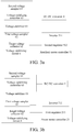
- the voltage stabilizing circuit 6 includes a first voltage sampler 61 and a target voltage collector 62.
- the first voltage sampler 61 samples the direct-current bus voltage output by the inverter 511 to obtain a first voltage sample value, and outputs the first voltage sample value to the first regulator 211 or the second regulator 512.
- the target voltage collector 62 obtains a target reference voltage and sends the target reference voltage to the first regulator 211 or the second regulator 512. Both the first regulator 211 and the second regulator 512 are configured to output the first regulating signal and the second regulating signal according to a voltage difference between the target reference voltage and the first voltage sample value.
- the output signal of the voltage stabilizing circuit 6 includes the first voltage sample value and the target reference voltage.
- the auxiliary motor controller 51 is connected to the DC-DC converter 4 through the voltage stabilizing circuit 6, and the auxiliary motor controller 51 outputs the direct-current bus voltage through the inverter 511.
- the first voltage sampler 61 samples the direct-current bus voltage output by the inverter 511 to obtain the first voltage sample value, and outputs the first voltage sample value to the second regulator 512.
- the target voltage collector 62 obtains the target reference voltage and sends the target reference voltage to the second regulator 512.
- the second regulator 512 outputs the first regulating signal and the second regulating signal according to the voltage difference between the target reference voltage and the first voltage sample value, regulates the d-axis current of the auxiliary motor 5 through the first regulating signal, and regulates the q-axis current of the auxiliary motor 5 through the second regulating signal, so that the auxiliary motor controller 51 controls the inverter 511 according to the d-axis current and the q-axis current of the auxiliary motor 5 when the power battery 3 is disconnected from the DC-DC converter 4, to keep the direct-current bus voltage output by the inverter 511 stable.
- the first voltage sampler 61 samples the direct-current bus voltage output by the inverter 511 to obtain the first voltage sample value, and outputs the first voltage sample value to the first regulator 211.
- the target voltage collector 62 obtains the target reference voltage and sends the target reference voltage to the first regulator 211.
- the first regulator 211 outputs the first regulating signal and the second regulating signal according to the voltage difference between the target reference voltage and the first voltage sample value, regulates the d-axis current of the auxiliary motor 5 through the first regulating signal, and regulates the q-axis current of the auxiliary motor 5 through the second regulating signal, so that the power motor controller 21 controls the inverter 511 according to the d-axis current and the q-axis current of the auxiliary motor 5 when the power battery 3 is disconnected from the DC-DC converter 4, and the auxiliary motor controller 51 fails, to keep the direct-current bus voltage output by the inverter 511 stable.
- the inverter 511 may be controlled by using pulse width modulation (PWM) to keep the direct-current bus voltage output by the inverter 511 stable.
- PWM pulse width modulation
- both the first regulator 211 and the second regulator 512 may include an error calculating unit a, a first PID regulating unit b, and a second PID regulating unit c. That is, the first regulator 211 and the second regulator 512 may use both a same structure and a same control principle
- the error calculating unit a is connected to the first voltage sampler 61 and the target voltage collector 62 respectively, and the error calculating unit a is configured to obtain the voltage difference between the target reference voltage and the first voltage sample value.
- the first PID regulating unit b is connected to the error calculating unit a, and the first PID regulating unit b regulates the voltage difference between the target reference voltage and the first voltage sample value to output the first regulating signal.
- the second PID regulating unit c is connected to the error calculating unit a, and the second PID regulating unit c regulates the voltage difference between the target reference voltage and the first voltage sample value to output the second regulating signal.
- the first voltage sampler 61 samples the direct-current bus voltage output by the inverter 511 to obtain the first voltage sample value in real time, and outputs the first voltage sample value to the error calculating unit a.
- the target voltage collector 62 obtains the target reference voltage and outputs the target reference voltage to the error calculating unit a.
- the error calculating unit a obtains the voltage difference between the target reference voltage and the first voltage sample value, outputs the difference to the first PID regulating unit b and the second PID regulating unit c respectively, and outputs the first regulating signal (that is, Id* in Fig. 4 ) through the first PID regulating unit b and outputs the second PID regulating unit (that is, Iq* in Fig.
- a three-phase current output by the auxiliary motor 5 is converted into the d-axis current Id and the q-axis current Iq in a dq coordinate system through 3S/2R conversion, and a difference between Id* and Id and a difference between Iq* and Iq are obtained respectively, and the differences are respectively controlled through corresponding PID regulators to obtain an ⁇ shaft voltage U ⁇ of the auxiliary motor 5 and a ⁇ shaft voltage U ⁇ of the auxiliary motor 5.
- U ⁇ and U ⁇ are input to an SVPWM module to output a three-phase duty ratio
- the inverter 511 is controlled by using the duty ratio
- the d-axis current Id and the q-axis current Iq output by the auxiliary motor 5 are regulated through the inverter 511
- the regulated d-axis current of the auxiliary motor is further regulated again through the first control signal
- the q-axis current of the auxiliary motor is regulated again through the second regulating signal. Therefore, closed-loop control of the d-axis current and the q-axis current of the auxiliary motor is formed, and the closed-loop control can keep the direct-current bus voltage output by the inverter 511 stable. That is, the direct-current voltage output by the auxiliary motor 5 to the DC-DC converter 4 during power generation is kept stable.
- the direct-current voltage output by the inverter 511 in the auxiliary motor controller 51 has a specific correlation with a counter electromotive force output by the auxiliary motor 5, and to ensure control efficiency, the voltage output by the inverter 511 may be set to a 3/2 phase voltage (that is, a maximum phase voltage is 2/3 of the direct-current bus voltage in a driving state). Therefore, the direct current voltage output by the inverter 511 has a specific relationship with a rotational speed of the auxiliary motor 5. When the rotational speed of the auxiliary motor 5 is higher, the direct current voltage output by the inverter 511 is higher. When the rotational speed of the auxiliary motor 5 is lower, the direct current voltage output by the inverter 511 is lower.
- the voltage stabilizing circuit 6 may further include a voltage stabilizer 63, a second voltage sampler 64, and a voltage stabilizing controller 65.
- the voltage stabilizer 63 is connected to a direct-current output end of the inverter 511, the voltage stabilizer 63 performs voltage stabilizing on the direct-current bus voltage output by the inverter 511, and an output end of the voltage stabilizer 63 is connected to an input end of the DC-DC converter 4.
- the second voltage sampler 64 samples the output voltage of the voltage stabilizer 63 to obtain a second voltage sample value.
- the voltage stabilizing controller 65 is connected to the voltage stabilizer 63 and the second voltage sampler 64 respectively, and the voltage stabilizing controller 65 is configured to control the output voltage of the voltage stabilizer 63 according to a preset reference voltage and the second voltage sample value to make the output voltage of the voltage stabilizer 63 fall within the preset voltage interval.
- a switch-type regulating circuit for example, a BOOST circuit
- a switch-type regulating circuit may be used as the voltage stabilizer 63, and not only can boost a voltage, but also has high control precision.
- a silicon carbide MOSFET for example, IMW120R45M1 of Infineon, may be used as a switch device in the BOOST circuit, has a withstand voltage of 1200 V and internal resistance of 45 m ⁇ , has features of a high withstand voltage, small internal resistance, and good heat-conducting performance, and has a loss several tens of times less than that of a high-speed IGBT having the same specification.
- 1EDI60N12AF of Infineon may be used as a drive chip of the voltage stabilizer 63, and is isolated by using a coreless transformer, and control is safe and reliable. It can be understood that, the drive chip may generate a drive signal.
- a BUCK-BOOST circuit may be used as the voltage stabilizer 63, can buck a voltage at a high speed and boost a voltage at a low speed, and has high control precision.
- a linear voltage stabilizing circuit or a three-terminal voltage stabilizing circuit may alternatively be used as the voltage stabilizer 63.
- the first voltage sampler 61 and the second voltage sampler 64 may have a same structure.
- both the first voltage sampler 61 and the second voltage sampler 64 may include a differential voltage circuit and have features of high precision and convenience in regulating an amplification factor.
- a PWM special modulation chip SG3525 may be used as the voltage stabilizing controller 65, and has features of a small volume, simple control, and a capability of outputting a stable PWM wave.
- a working procedure 100 of the power system of a hybrid electric vehicle is:
- the second voltage sampler 64 samples an output voltage of the voltage stabilizer 63 to obtain a second voltage sample value, and outputs the second voltage sample value to the chip SG3525.
- the chip SG3525 may set a reference voltage, compares the reference voltage with the second voltage sample value, may generate two paths of PWM waves by combining triangular waves generated by the chip SG3525, and controls the voltage stabilizer 63 through the two paths of PWM waves, to make a voltage output by the voltage stabilizer 63 to the DC-DC converter 4 fall within in a preset voltage interval, for example, 11 V to 13 V, thereby ensuring normal working of a low-voltage load in the hybrid electric vehicle.
- SG3525 may emit a PWM wave with a large duty ratio for boosting the voltage.
- the auxiliary motor 5 and the DC-DC converter 4 have an independent voltage-stabilizing power supply channel.
- the power battery 3 fails and is disconnected from the DC-DC converter 4, or the auxiliary motor controller 52 fails, low-voltage power consumption of the entire vehicle can be ensured through the independent voltage-stabilizing power supply channel of the auxiliary motor 5 and the DC-DC converter 4, thereby ensuring that the entire vehicle can travel in a pure fuel mode, and improving a traveling distance of the entire vehicle.
- the voltage stabilizing circuit 6 is connected to the incoming line of the DC-DC converter 4.
- the power motor 2 further includes a power motor controller 21, where the auxiliary motor controller 51 is connected to the power motor controller 21, and is connected to the DC-DC converter 4 through the voltage stabilizing circuit 6. After being converted by the inverter 511, electric energy generated by the auxiliary motor 5 during power generation may be converted into a high-voltage direct current such as a 600 V high-voltage direct current, thereby supplying power to at least one of the power motor 2 and the DC-DC converter 4.
- a high-voltage direct current such as a 600 V high-voltage direct current
- the power motor controller 21 may further include a DC-AC conversion unit.
- the DC-AC conversion unit converts the high-voltage direct current output by the inverter 511 into an alternating current to charge the power motor 4.
- the inverter 511 of the auxiliary motor controller 51 includes a first direct-current end DC1, the power motor controller 21 includes a second direct-current end DC2, and the DC-DC converter 4 includes a third direct-current end DC3.
- the first direct-current end DC1 of the auxiliary motor controller 51 is connected to the third direct-current end DC3 of the DC-DC converter 4 through the voltage stabilizing circuit 6 to provide a stable voltage to the DC-DC converter 4, and the DC-DC converter 4 may perform DC-DC conversion on the stabilized direct current.
- the inverter 511 of the auxiliary motor controller 51 may further output the high-voltage direct current to the power motor controller 21 through the first direct-current end DC1 to supply power to the power motor 2.
- the DC-DC converter 4 is further connected to an electrical device 10 and a low-voltage storage battery 20 in the hybrid electric vehicle to supply power to the electrical device 10 and the low-voltage storage battery 20 respectively, and the low-voltage storage battery 20 is further connected to the electrical device 10.
- the DC-DC converter 4 further includes a fourth direct-current end DC4.
- the DC-DC converter 4 may convert the high-voltage direct current output by the auxiliary motor 5 through the auxiliary motor controller 51 into the low-voltage direct current, and outputs the low-voltage direct current through the fourth direct-current end DC4.
- the fourth direct-current end DC4 of the DC-DC converter 4 is connected to the electrical device 10 for supplying power to the electrical device 10, where the electrical device 10 may be a low-voltage power-consuming device, and includes, but is not limited to, a car light, a radio, and the like.
- the fourth direct-current end DC4 of the DC-DC converter 4 is alternatively connected to the low-voltage storage battery 20 for supplying power to the low-voltage storage battery 20.
- the low-voltage storage battery 20 is contacted to the electrical device 10 to supply power to the electrical device 10.
- the low-voltage storage battery 20 may supply power to the electrical device 10, thereby ensuring low-voltage power consumption of the entire vehicle, ensuring that the entire vehicle can travel in a pure fuel mode, and improving a traveling distance of the entire vehicle.
- a low voltage may refer to a voltage of 12 V or 24 V
- a high voltage may refer to a voltage of 600 V
- a preset voltage interval may refer to 11 V to 13 V or 23 V to 25 V, but this is not limited thereto.
- the engine outputs power to a wheel of the hybrid electric vehicle through the clutch
- the power motor outputs a driving force to a wheel of the hybrid electric vehicle
- the power battery supplies power to the power motor
- the voltage stabilizing circuit performs voltage stabilizing on the direct current output by the auxiliary motor to the DC-DC converter during power generation.
- the second regulator controls the voltage stabilizing circuit to perform voltage stabilizing when the power battery is disconnected from the DC-DC converter, and the auxiliary motor controller is valid
- the first regulator controls the voltage stabilizing circuit to perform voltage stabilizing when the power battery is disconnected from the DC-DC converter, and the auxiliary motor controller fails.
- the power system not only can maintain low-speed electric balance and low-speed smoothness of the entire vehicle and improve the performance of the entire vehicle, and but also keep the input voltage of the DC-DC converter stable when the power battery fails or both the power battery and the auxiliary motor controller fail, thereby ensuring normal working of the DC-DC converter and normal traveling of the entire vehicle.
- the present disclosure further provides a hybrid electric vehicle.
- Fig. 6 is a structural block diagram of a hybrid electric vehicle according to an embodiment of the present disclosure. As shown in Fig. 6 , the hybrid electric vehicle 200 includes the foregoing power system 100 of a hybrid electric vehicle.
- the power system of a hybrid electric vehicle may maintain low-speed electric balance and low-speed smoothness of the entire vehicle and improve performance of the entire vehicle, and may keep the input voltage of the DC-DC converter stable when the power battery fails or both the power battery and the auxiliary motor controller fail, thereby ensuring normal working of the DC-DC converter and normal traveling of the entire vehicle.
- orientation or position relationships indicated by the terms such as “center”, “longitudinal”, “transverse”, “length”, “width”, “thickness”, “on”, “below”, “front”, “rear”, “left”, “right”, “vertical”, “horizontal”, “top”, “bottom”, “inside”, “outside”, “clockwise”, “counterclockwise”, “axial “, “radial”, and “circumferential” are based on orientation or position relationships shown in the accompanying drawings, and are intended only to conveniently describe the present disclosure and simplify the description, rather than indicating or implying that the mentioned apparatus or component needs to have a particular orientation or needs to be constructed and operated in a particular orientation. Therefore, such terms should not be construed as limiting of the present disclosure.
- first and second are only used to describe the objective and cannot be understood as indicating or implying relative importance or implying a quantity of the indicated technical features. Therefore, features defining “first” and “second” can explicitly or implicitly include at least one of the features. In the descriptions of the present disclosure, unless explicitly specified, "a plurality of" means at least two, for example, two or three.
- connection may be a fixed connection, a detachable connection, or an integral connection; or the connection may be a mechanical connection or an electrical connection; or the connection may be a direct connection, an indirect connection through an intermediary, internal communication between two components or interaction relationship between the two components.
- the first feature being located “above” or “below” the second feature may be the first feature being in direct contact with the second feature, or the first feature being in indirect contact with the second feature through an intermediary.
- the first feature being located “above” the second feature may be the first feature being located directly above or obliquely above the second feature, or may simply indicate that the first feature is higher in level than the second feature.
- the first feature being located “below” the second feature may be the first feature being located directly below or obliquely below the second feature, or may simply indicate that the first feature is lower in level than the second feature.
- description of reference terms such as "one embodiment”, “some embodiments”, “example”, “specific example” or “some examples” means including specific features, structures, materials, or features described in the embodiment or example in at least one embodiment or example of the present disclosure.
- schematic descriptions of the foregoing terms do not necessarily direct at a same embodiment or example.
- the described specific features, structures, materials, or features can be combined in a proper manner in any one or more embodiments or examples.
- a person skilled in the art can combine or group different embodiments or examples that are described in this specification and features of the different embodiments or examples.
Landscapes
- Engineering & Computer Science (AREA)
- Transportation (AREA)
- Mechanical Engineering (AREA)
- Power Engineering (AREA)
- Automation & Control Theory (AREA)
- Chemical & Material Sciences (AREA)
- Sustainable Energy (AREA)
- Sustainable Development (AREA)
- Life Sciences & Earth Sciences (AREA)
- Combustion & Propulsion (AREA)
- Human Computer Interaction (AREA)
- Health & Medical Sciences (AREA)
- Biomedical Technology (AREA)
- General Health & Medical Sciences (AREA)
- Electric Propulsion And Braking For Vehicles (AREA)
- Hybrid Electric Vehicles (AREA)
Abstract
Description
- This application is based upon and claims priority to Chinese Patent Application Serial No.
201710910647.1, filed on September 29, 2017 - The present disclosure relates to the field of hybrid electric vehicle technologies, and in particular, to a power system of a hybrid electric vehicle and a hybrid electric vehicle.
- In a hybrid electric vehicle, a voltage output by a motor is rectified by an inverter for charging a power battery, and the voltage on an output end of the inverter is not controlled. However, because the output end is connected to the power battery in parallel, the power battery is equivalent to a huge capacitive load and can stabilize a voltage on a main circuit, so that an effect on a DC-DC converter of a next stage is small. In addition, a high voltage can be directly bucked to a low voltage, such as 12 V, through the DC-DC converter to supply power to low-voltage electrical appliances of the entire vehicle.
- However, once the power battery is disconnected, the voltage output by the motor is uncontrollable, the voltage output by the motor needs to be stabilized for subsequent use of a load. Because voltage fluctuation on an inverter side is very large, an amplitude and a frequency of a counter electromotive force output by the motor vary with a variation of the load (that is, a variation of the rotational speed of an engine). For example, at a high rotational speed, the counter electromotive force is very high, and the voltage output through rectification and voltage stabilizing tends to be high. If a brake rectification mode is used, the output voltage is uncontrollable once the power battery is disconnected. If uncontrolled rectification is used, losses are very large.
- An objective of the present disclosure is to resolve one of the technical problems in the foregoing technology at least to some extent.
- Therefore, an objective of the present disclosure is to provide a power system of a hybrid electric vehicle. The power system can keep an input voltage of a DC-DC converter stable, and ensures normal working of the DC-DC converter.
- Another objective of the present disclosure is to provide a hybrid electric vehicle.
- To achieve the foregoing objectives, an embodiment of a first aspect of the present disclosure provides a power system for a hybrid electric vehicle, including: an engine, where the engine outputs power to a wheel of the hybrid electric vehicle through a clutch; a power motor, where the power motor is configured to output a driving force to a wheel of the hybrid electric vehicle, the power motor includes a power motor controller, and the power motor controller includes a first regulator; a power battery, where the power battery is configured to supply power to the power motor; a DC-DC converter; an auxiliary motor, connected to the engine, where the auxiliary motor is connected to the power motor, the DC-DC converter, and the power battery respectively, the auxiliary motor includes an auxiliary motor controller, and the auxiliary motor controller includes an inverter and a second regulator; and a voltage stabilizing circuit, where the voltage stabilizing circuit is connected between the auxiliary motor and the DC-DC converter, and the voltage stabilizing circuit performs voltage stabilizing on a direct current output by the auxiliary motor to the DC-DC converter during power generation. The second regulator is configured to control the voltage stabilizing circuit to perform voltage stabilizing when the power battery is disconnected from the DC-DC converter, and the auxiliary motor controller is valid. The first regulator is configured to control the voltage stabilizing circuit to perform voltage stabilizing when the power battery is disconnected from the DC-DC converter, and the auxiliary motor controller fails.
- According to the power system of a hybrid electric vehicle provided in the embodiments of the present disclosure, the engine outputs power to a wheel of the hybrid electric vehicle through the clutch, the power motor outputs a driving force to a wheel of the hybrid electric vehicle, the power battery supplies power to the power motor, and the voltage stabilizing circuit performs voltage stabilizing on the direct current output by the auxiliary motor to the DC-DC converter during power generation. In addition, the second regulator controls the voltage stabilizing circuit to perform voltage stabilizing when the power battery is disconnected from the DC-DC converter, and the auxiliary motor controller is valid, and the first regulator controls the voltage stabilizing circuit to perform voltage stabilizing when the power battery is disconnected from the DC-DC converter, and the auxiliary motor controller fails. Therefore, the power system not only can maintain low-speed electric balance and low-speed smoothness of the entire vehicle and improve the performance of the entire vehicle, and but also keep the input voltage of the DC-DC converter stable when the power battery fails or both the power battery and the auxiliary motor controller fail, thereby ensuring normal working of the DC-DC converter and normal traveling of the entire vehicle.
- Further, the present disclosure provides a hybrid electric vehicle, including the foregoing power system of a hybrid electric vehicle of the present disclosure.
- According to the hybrid electric vehicle provided in the embodiments of the present disclosure, the power system of a hybrid electric vehicle not only can maintain low-speed electric balance and low-speed smoothness of the entire vehicle and improve performance of the entire vehicle, and but also can keep the input voltage of the DC-DC converter stable when the power battery fails or both the power battery and the auxiliary motor controller fail, thereby ensuring that normal working of the DC-DC converter and normal traveling of the entire vehicle.
- The foregoing and/or additional aspects and advantages of the present disclosure will become apparent and comprehensible in the description made with reference to the following accompanying drawings, wherein:
-
Fig. 1 is a structural block diagram of a power system of a hybrid electric vehicle according to an embodiment of the present disclosure; -
Fig. 2a is a schematic structural diagram of a power system of a hybrid electric vehicle according to an embodiment of the present disclosure; -
Fig. 2b is a schematic structural diagram of a power system of a hybrid electric vehicle according to another embodiment of the present disclosure; -
Fig. 2c is a schematic structural diagram of a power system of a hybrid electric vehicle according to still another embodiment of the present disclosure; -
Fig. 3a is a structural block diagram of a voltage stabilizing circuit according to an embodiment of the present disclosure; -
Fig. 3b is a structural block diagram of a voltage stabilizing circuit according to another embodiment of the present disclosure; -
Fig. 4 is a schematic diagram of voltage stabilizing control according to an embodiment of the present disclosure; -
Fig. 5 is a structural block diagram of a power system of a hybrid electric vehicle according to a specific embodiment of the present disclosure; and -
Fig. 6 is a structural block diagram of a hybrid electric vehicle according to an embodiment of the present disclosure. - The following describes embodiments of the present disclosure in detail. Examples of the embodiments are shown in the accompanying drawings, and same or similar reference signs in all the accompanying drawings indicate same or similar components or components having same or similar functions. The embodiments described below with reference to the accompanying drawings are exemplary, and are intended to explain the present disclosure and cannot be construed as a limitation to the present disclosure.
- The following describes a power system of a hybrid electric vehicle and a hybrid electric vehicle according to the embodiments of the present disclosure with reference to the accompanying drawings.
-
Fig. 1 is a structural block diagram of a power system of a hybrid electric vehicle according to an embodiment of the present disclosure. As shown inFig. 1 , thepower system 100 of a hybrid electric vehicle includes: anengine 1, apower motor 2, apower battery 3, a DC-DC converter 4, anauxiliary motor 5, and avoltage stabilizing circuit 6. - With reference to
Fig. 1 to Fig. 3 , theengine 1 outputs power to awheel 8 of the hybrid electric vehicle through aclutch 7. Thepower motor 2 is configured to output a driving force to awheel 8 of the hybrid electric vehicle. That is, the power system of this embodiment of the present disclosure may provide power for normal traveling of the hybrid electric vehicle through theengine 1 and/or thepower motor 2. In other words, in some embodiments of the present disclosure, a power source of the power system may be theengine 1 and thepower motor 2, and either of theengine 1 and thepower motor 2 can individually output power to thewheels 8, or theengine 1 and thepower motor 2 may simultaneously output the power to thewheels 8. - The
power battery 3 is configured to supply power to thepower motor 2. Theauxiliary motor 5 is connected to theengine 1. For example, theauxiliary motor 5 may be connected to theengine 1 through a wheel train end of theengine 1, and theauxiliary motor 5 is connected to thepower motor 2, the DC-DC converter 4, and thepower battery 3 respectively. Thevoltage stabilizing circuit 6 is connected between theauxiliary motor 5 and the DC-DC converter 4, and thevoltage stabilizing circuit 6 performs voltage stabilizing on a direct current output by theauxiliary motor 5 to the DC-DC converter 4 during power generation, so that a stabilized voltage is supplied to low-voltage electrical appliances of the entire vehicle through the DC-DC converter 4. In other words, after electric energy output by theauxiliary motor 5 during power generation passes through thevoltage stabilizing circuit 6, a stabilized voltage is output and supplied to the DC-DC converter 4. - Therefore, the
power motor 2 and theauxiliary motor 5 may serve as a driving motor and a generator respectively, so that theauxiliary motor 5 can have a higher power-generation power and higher generation efficiency at a low speed, thereby meeting power consumption requirements of low-speed traveling, maintaining low-speed electric balance of the entire vehicle, maintaining low-speed smoothness, and improving performance of the entire vehicle. In addition, thevoltage stabilizing circuit 6 performs voltage stabilizing on the direct current output by theauxiliary motor 5 to the DC-DC converter 4 during power generation, so that an input voltage of the DC-DC converter 4 is kept stable, thereby ensuring normal working of the DC-DC converter. - When the
auxiliary motor 5 is driven by theengine 1 to generate power, at least one of charging thepower battery 3, supplying power to thepower motor 2, and supplying power to the DC-DC converter 4 may be implemented. In other words, theengine 1 may drive theauxiliary motor 5 to generate power, and electric energy generated by theauxiliary motor 5 may be supplied to at least one of thepower battery 3, thepower motor 2, and the DC-DC converter 4. It should be understood that, theengine 1 may drive theauxiliary motor 5 to generate power while outputting power to thewheels 8, or may solely drive theauxiliary motor 5 to generate power. - The
auxiliary motor 5 may be a BSG motor. It should be noted that, theauxiliary motor 5 is a high-voltage motor. For example, a generating voltage of theauxiliary motor 5 is equivalent to a voltage of thepower battery 3, so that the electric energy generated by theauxiliary motor 5 can be directly used to charge thepower battery 3 without being subjected to voltage conversion, or may be directly supplied to thepower motor 2 and/or the DC-DC converter 4. In addition, theauxiliary motor 5 may alternatively be a high-efficiency generator. For example, theauxiliary motor 5 is driven to generate power at an idling speed of theengine 1, thereby implementing generating efficiency of 97% or above. - It should be noted that, the
voltage stabilizing circuit 6 may be disposed on an output line of theauxiliary motor 5, and theauxiliary motor 5 is connected to thepower motor 2, thepower battery 3, and the DC-DC converter 4 respectively through thevoltage stabilizing circuit 6. As shown inFig. 2b andFig. 2c , in this case, the stabilized voltage may be output through thevoltage stabilizing circuit 6 when theauxiliary motor 5 generates power, thereby charging thepower battery 3 at a stable voltage, supplying power to thepower motor 2 at a stable voltage, and supplying power to the DC-DC converter 4 at a stable voltage. Therefore, whether thepower battery 3 and the DC-DC converter 4 are connected or not, normal working of the DC-DC converter 4 can be ensured. Thevoltage stabilizing circuit 6 may alternatively be disposed on an incoming line of the DC-DC converter 4, and theauxiliary motor 5 may be connected to the DC-DC converter 4 and thepower battery 3 respectively. At the same time, thepower battery 3 may be connected to the DC-DC converter 4. Therefore, as shown inFig. 1 andFig. 2a , when thepower battery 3 is disconnected from the DC-DC converter 4, the voltage output to the DC-DC converter 4 by theauxiliary motor 5 during power generation is still stable, thereby ensuring normal working of the DC-DC converter 4. - The
auxiliary motor 5 may be configured to start theengine 1. That is, theauxiliary motor 5 may implement a function of starting theengine 1. For example, when starting theengine 1, theauxiliary motor 5 may drive a crankshaft of theengine 1 to rotate, to enable a piston of theengine 1 to reach an ignition position, thereby starting theengine 1, and therefore, theauxiliary motor 5 can implement a function of a starter in the related art. - As stated above, both the
engine 1 and thepower motor 2 may be configured to drive thewheels 8 of the hybrid electric vehicle. For example, as shown inFig. 2a and Fig. 2b , theengine 1 and thepower motor 2 drive a same wheel, for example, a pair of front wheels 81 (including a left front wheel and a right front wheel), of the hybrid electric vehicle together. For another example, as shown inFig. 2c , theengine 1 may drive a first wheel, for example, a pair of front wheels 81 (including a left front wheel and a right front wheel), of the hybrid electric vehicle, and thepower motor 2 may drive a second wheel, for example, a pair of rear wheels 82 (including a left rear wheel and a right rear wheel), of the hybrid electric vehicle. - When the
engine 1 and thepower motor 2 drive the pair offront wheels 81 together, an overall driving force of the power system is output to the pair offront wheels 81, and a two wheel drive mode may be adopted for the entire vehicle. When theengine 1 drives the pair offront wheels 81, and thepower motor 2 drives the pair of rear wheels 82, the driving force of the power system is output to the pair offront wheels 81 and the pair of rear wheels 82 respectively, and a four wheel drive mode may be adopted for the entire vehicle. - In the two wheel drive mode, with reference to
Fig. 2a and Fig. 2b , thepower system 100 of a hybrid electric vehicle further includes a main reducer 9 and afirst transmission 91, where theengine 1 outputs power to the first wheel, for example, the pair offront wheels 81, of the hybrid electric vehicle through theclutch 7, thefirst transmission 91, and the main reducer 9, and thepower motor 2 outputs a driving force to the first wheel, for example, the pair offront wheels 81, of the hybrid electric vehicle through the main reducer 9. - In the four wheel drive mode, with reference to
Fig. 2c , thepower system 100 of a hybrid electric vehicle further includes afirst transmission 91 and a second transmission 92, where theengine 1 outputs power to the first wheel, for example, the pair offront wheels 81, of the hybrid electric vehicle through theclutch 7 and thefirst transmission 91, and thepower motor 2 outputs a driving force to the second wheel, for example, the pair of rear wheels 82, of the hybrid electric vehicle through the second transmission 92. - The
clutch 7 and thefirst transmission 91 may be integrally disposed. - In this embodiment of the present disclosure, because the generating voltage of the
auxiliary motor 5 is supplied to two ends of thepower battery 3, the voltage input to the DC-DC converter 4 is stable when thepower battery 3 is connected to the DC-DC converter 4. When thepower battery 3 fails or is damaged, and is disconnected from the DC-DC converter 4, it is necessary to control electric energy output by theauxiliary motor 5 during power generation at this moment, that is, voltage stabilizing may be performed through thevoltage stabilizing circuit 6 on the direct current output by theauxiliary motor 5 to the DC-DC converter 4 during power generation. - In this embodiment of the present disclosure, as shown in
Fig. 1 , thepower motor 2 includes apower motor controller 21, and thepower motor controller 21 includes afirst regulator 211. Theauxiliary motor 5 includes anauxiliary motor controller 51, and theauxiliary motor controller 51 includes aninverter 511 and asecond regulator 512. - The
second regulator 512 is configured to control thevoltage stabilizing circuit 6 to perform voltage stabilizing when thepower battery 3 is disconnected from the DC-DC converter 4, and theauxiliary motor controller 51 is valid. Thefirst regulator 211 is configured to control thevoltage stabilizing circuit 6 to perform voltage stabilizing when thepower battery 3 is disconnected from the DC-DC converter 4, and theauxiliary motor controller 51 fails. - It should be noted that, the failure of the
auxiliary motor controller 51 may indicate that theauxiliary motor controller 51 cannot perform voltage stabilizing. On the contrary, the validity of theauxiliary motor controller 51 may indicate that theauxiliary motor controller 51 can perform voltage stabilizing. - That is, when the
power battery 3 is disconnected, the entire vehicle still needs to travel normally, and theauxiliary motor controller 51 performs voltage stabilizing. If theauxiliary motor controller 51 fails, the power motor controller is responsible for voltage stabilizing, so that when both thepower battery 3 and theauxiliary motor controller 51 fail at the same time, the entire vehicle can still travel normally, and an electric quantity of a storage battery can be prevented from being consumed. - A voltage stabilizing procedure of this embodiment of the present disclosure is described in a parallel-series mode and a parallel mode respectively.
- When the entire vehicle travels normally, and the hybrid electric vehicle works in the parallel-series mode, if a main contactor of a battery management system (BMS) of the
power battery 3 is disconnected, indicating that thepower battery 3 is disconnected, whether theauxiliary motor controller 51 fails is further determined. If theauxiliary motor controller 51 fails, theauxiliary motor controller 51 stops voltage stabilizing, and thepower motor controller 21 performs voltage stabilizing. If theauxiliary motor controller 51 fails, thepower motor controller 21 stops voltage stabilizing, and theauxiliary motor controller 51 performs voltage stabilizing. - When the entire vehicle travels normally, and the hybrid electric vehicle works in the parallel mode, if the main contactor of the BMS of the
power battery 3 is disconnected, indicating that thepower battery 3 is disconnected, whether theauxiliary motor controller 51 fails is further determined. If theauxiliary motor controller 51 fails, theauxiliary motor controller 51 stops voltage stabilizing, and thepower motor controller 21 performs voltage stabilizing. If theauxiliary motor controller 51 fails, thepower motor controller 21 stops voltage stabilizing, and theauxiliary motor controller 51 performs voltage stabilizing. - In addition, in some embodiments of the present disclosure, whether the
power battery 3 is disconnected or not and whether theauxiliary motor controller 51 fails or not may be determined by an entire vehicle controller of the hybrid electric vehicle. For example, the entire vehicle controller may communicate with thepower battery 3 through a CAN bus to determine whether thepower battery 3 is disconnected, and the entire vehicle controller may communicate with theauxiliary motor controller 51 through the CAN bus to determine whether theauxiliary motor controller 51 fails, and sends a voltage stabilizing instruction to theauxiliary motor controller 51 when thepower battery 3 is disconnected, and theauxiliary motor controller 51 is valid. The entire vehicle controller may communicate with thepower motor controller 21 through the CAN bus to send a voltage stabilizing instruction to thepower motor controller 21 when thepower battery 3 is disconnected, and theauxiliary motor controller 51 fails. Alternatively, in some other embodiments, the entire vehicle controller may alternatively determine whether thepower battery 3 is disconnected or not and whether theauxiliary motor controller 51 fails or not through communication with thepower battery 3, theauxiliary motor controller 51, and thepower motor controller 21. Theauxiliary motor controller 51 may communicate with thepower battery 3 to determine whether thepower battery 3 is disconnected, and performs voltage stabilizing when thepower battery 3 is disconnected, and theauxiliary motor controller 51 is valid, and theauxiliary motor controller 51 may further send a voltage stabilizing instruction to thepower motor controller 21 when theauxiliary motor controller 51 fails. - According to an embodiment of the present disclosure, both the
first regulator 211 and thesecond regulator 512 are configured to output a first regulating signal and a second regulating signal according to an output signal of thevoltage stabilizing circuit 6, to keep a direct-current bus voltage output by theinverter 511 stable, where the first regulating signal is used for regulating a d-axis current of theauxiliary motor 5, and the second regulating signal is used for regulating a q-axis current of theauxiliary motor 5. - That is, when the
first regulator 211 controls thevoltage stabilizing circuit 6 to perform voltage stabilizing, thefirst regulator 211 outputs the first regulating signal and the second regulating signal according to the output signal of thevoltage stabilizing circuit 6. When thesecond regulator 512 controls thevoltage stabilizing circuit 6 to perform voltage stabilizing, thesecond regulator 512 outputs the first regulating signal and the second regulating signal according to the output signal of thevoltage stabilizing circuit 6. - In some embodiments, as shown in
Fig. 3a and Fig. 3b , thevoltage stabilizing circuit 6 includes afirst voltage sampler 61 and atarget voltage collector 62. Thefirst voltage sampler 61 samples the direct-current bus voltage output by theinverter 511 to obtain a first voltage sample value, and outputs the first voltage sample value to thefirst regulator 211 or thesecond regulator 512. Thetarget voltage collector 62 obtains a target reference voltage and sends the target reference voltage to thefirst regulator 211 or thesecond regulator 512. Both thefirst regulator 211 and thesecond regulator 512 are configured to output the first regulating signal and the second regulating signal according to a voltage difference between the target reference voltage and the first voltage sample value. The output signal of thevoltage stabilizing circuit 6 includes the first voltage sample value and the target reference voltage. - The
auxiliary motor controller 51 is connected to the DC-DC converter 4 through thevoltage stabilizing circuit 6, and theauxiliary motor controller 51 outputs the direct-current bus voltage through theinverter 511. - When the
second regulator 512 controls thevoltage stabilizing circuit 6 to perform voltage stabilizing, as shown inFig. 3a , thefirst voltage sampler 61 samples the direct-current bus voltage output by theinverter 511 to obtain the first voltage sample value, and outputs the first voltage sample value to thesecond regulator 512. Thetarget voltage collector 62 obtains the target reference voltage and sends the target reference voltage to thesecond regulator 512. Thesecond regulator 512 outputs the first regulating signal and the second regulating signal according to the voltage difference between the target reference voltage and the first voltage sample value, regulates the d-axis current of theauxiliary motor 5 through the first regulating signal, and regulates the q-axis current of theauxiliary motor 5 through the second regulating signal, so that theauxiliary motor controller 51 controls theinverter 511 according to the d-axis current and the q-axis current of theauxiliary motor 5 when thepower battery 3 is disconnected from the DC-DC converter 4, to keep the direct-current bus voltage output by theinverter 511 stable. - When the
first regulator 211 controls thevoltage stabilizing circuit 6 to perform voltage stabilizing, as shown inFig. 3b , thefirst voltage sampler 61 samples the direct-current bus voltage output by theinverter 511 to obtain the first voltage sample value, and outputs the first voltage sample value to thefirst regulator 211. Thetarget voltage collector 62 obtains the target reference voltage and sends the target reference voltage to thefirst regulator 211. Thefirst regulator 211 outputs the first regulating signal and the second regulating signal according to the voltage difference between the target reference voltage and the first voltage sample value, regulates the d-axis current of theauxiliary motor 5 through the first regulating signal, and regulates the q-axis current of theauxiliary motor 5 through the second regulating signal, so that thepower motor controller 21 controls theinverter 511 according to the d-axis current and the q-axis current of theauxiliary motor 5 when thepower battery 3 is disconnected from the DC-DC converter 4, and theauxiliary motor controller 51 fails, to keep the direct-current bus voltage output by theinverter 511 stable. - In some examples, the
inverter 511 may be controlled by using pulse width modulation (PWM) to keep the direct-current bus voltage output by theinverter 511 stable. As shown inFig. 4 , both thefirst regulator 211 and thesecond regulator 512 may include an error calculating unit a, a first PID regulating unit b, and a second PID regulating unit c. That is, thefirst regulator 211 and thesecond regulator 512 may use both a same structure and a same control principle - The error calculating unit a is connected to the
first voltage sampler 61 and thetarget voltage collector 62 respectively, and the error calculating unit a is configured to obtain the voltage difference between the target reference voltage and the first voltage sample value. The first PID regulating unit b is connected to the error calculating unit a, and the first PID regulating unit b regulates the voltage difference between the target reference voltage and the first voltage sample value to output the first regulating signal. The second PID regulating unit c is connected to the error calculating unit a, and the second PID regulating unit c regulates the voltage difference between the target reference voltage and the first voltage sample value to output the second regulating signal. - As shown in
Fig. 4 , thefirst voltage sampler 61 samples the direct-current bus voltage output by theinverter 511 to obtain the first voltage sample value in real time, and outputs the first voltage sample value to the error calculating unit a. Thetarget voltage collector 62 obtains the target reference voltage and outputs the target reference voltage to the error calculating unit a. The error calculating unit a obtains the voltage difference between the target reference voltage and the first voltage sample value, outputs the difference to the first PID regulating unit b and the second PID regulating unit c respectively, and outputs the first regulating signal (that is, Id* inFig. 4 ) through the first PID regulating unit b and outputs the second PID regulating unit (that is, Iq* inFig. 4 ) through the second PID regulating unit c. In this case, a three-phase current output by theauxiliary motor 5 is converted into the d-axis current Id and the q-axis current Iq in a dq coordinate system through 3S/2R conversion, and a difference between Id* and Id and a difference between Iq* and Iq are obtained respectively, and the differences are respectively controlled through corresponding PID regulators to obtain an α shaft voltage Uα of theauxiliary motor 5 and a β shaft voltage Uβ of theauxiliary motor 5. Uα and Uβ are input to an SVPWM module to output a three-phase duty ratio, theinverter 511 is controlled by using the duty ratio, the d-axis current Id and the q-axis current Iq output by theauxiliary motor 5 are regulated through theinverter 511, the regulated d-axis current of the auxiliary motor is further regulated again through the first control signal, and the q-axis current of the auxiliary motor is regulated again through the second regulating signal. Therefore, closed-loop control of the d-axis current and the q-axis current of the auxiliary motor is formed, and the closed-loop control can keep the direct-current bus voltage output by theinverter 511 stable. That is, the direct-current voltage output by theauxiliary motor 5 to the DC-DC converter 4 during power generation is kept stable. - It should be noted that, the direct-current voltage output by the
inverter 511 in theauxiliary motor controller 51 has a specific correlation with a counter electromotive force output by theauxiliary motor 5, and to ensure control efficiency, the voltage output by theinverter 511 may be set to a 3/2 phase voltage (that is, a maximum phase voltage is 2/3 of the direct-current bus voltage in a driving state). Therefore, the direct current voltage output by theinverter 511 has a specific relationship with a rotational speed of theauxiliary motor 5. When the rotational speed of theauxiliary motor 5 is higher, the direct current voltage output by theinverter 511 is higher. When the rotational speed of theauxiliary motor 5 is lower, the direct current voltage output by theinverter 511 is lower. - To ensure that the direct current voltage input to the DC-
DC converter 4 falls within a preset voltage interval, in some embodiments of the present disclosure, as shown inFig. 3a and Fig. 3b , thevoltage stabilizing circuit 6 may further include avoltage stabilizer 63, asecond voltage sampler 64, and avoltage stabilizing controller 65. - The
voltage stabilizer 63 is connected to a direct-current output end of theinverter 511, thevoltage stabilizer 63 performs voltage stabilizing on the direct-current bus voltage output by theinverter 511, and an output end of thevoltage stabilizer 63 is connected to an input end of the DC-DC converter 4. Thesecond voltage sampler 64 samples the output voltage of thevoltage stabilizer 63 to obtain a second voltage sample value. Thevoltage stabilizing controller 65 is connected to thevoltage stabilizer 63 and thesecond voltage sampler 64 respectively, and thevoltage stabilizing controller 65 is configured to control the output voltage of thevoltage stabilizer 63 according to a preset reference voltage and the second voltage sample value to make the output voltage of thevoltage stabilizer 63 fall within the preset voltage interval. - In some examples, a switch-type regulating circuit, for example, a BOOST circuit, may be used as the
voltage stabilizer 63, and not only can boost a voltage, but also has high control precision. A silicon carbide MOSFET, for example, IMW120R45M1 of Infineon, may be used as a switch device in the BOOST circuit, has a withstand voltage of 1200 V and internal resistance of 45 mΩ, has features of a high withstand voltage, small internal resistance, and good heat-conducting performance, and has a loss several tens of times less than that of a high-speed IGBT having the same specification. 1EDI60N12AF of Infineon may be used as a drive chip of thevoltage stabilizer 63, and is isolated by using a coreless transformer, and control is safe and reliable. It can be understood that, the drive chip may generate a drive signal. - In some other examples, a BUCK-BOOST circuit may be used as the
voltage stabilizer 63, can buck a voltage at a high speed and boost a voltage at a low speed, and has high control precision. - In still other examples, a linear voltage stabilizing circuit or a three-terminal voltage stabilizing circuit (such as LM317 and 7805) may alternatively be used as the
voltage stabilizer 63. - It can be understood that, to facilitate circuit design, the
first voltage sampler 61 and thesecond voltage sampler 64 may have a same structure. For example, both thefirst voltage sampler 61 and thesecond voltage sampler 64 may include a differential voltage circuit and have features of high precision and convenience in regulating an amplification factor. - In some examples, a PWM special modulation chip SG3525 may be used as the
voltage stabilizing controller 65, and has features of a small volume, simple control, and a capability of outputting a stable PWM wave. - For example, a working
procedure 100 of the power system of a hybrid electric vehicle is: Thesecond voltage sampler 64 samples an output voltage of thevoltage stabilizer 63 to obtain a second voltage sample value, and outputs the second voltage sample value to the chip SG3525. The chip SG3525 may set a reference voltage, compares the reference voltage with the second voltage sample value, may generate two paths of PWM waves by combining triangular waves generated by the chip SG3525, and controls thevoltage stabilizer 63 through the two paths of PWM waves, to make a voltage output by thevoltage stabilizer 63 to the DC-DC converter 4 fall within in a preset voltage interval, for example, 11 V to 13 V, thereby ensuring normal working of a low-voltage load in the hybrid electric vehicle. - It should be noted that, if the output direct-current bus voltage is excessively low, and the second voltage sample value is very small, SG3525 may emit a PWM wave with a large duty ratio for boosting the voltage.
- Therefore, the
auxiliary motor 5 and the DC-DC converter 4 have an independent voltage-stabilizing power supply channel. When thepower battery 3 fails and is disconnected from the DC-DC converter 4, or the auxiliary motor controller 52 fails, low-voltage power consumption of the entire vehicle can be ensured through the independent voltage-stabilizing power supply channel of theauxiliary motor 5 and the DC-DC converter 4, thereby ensuring that the entire vehicle can travel in a pure fuel mode, and improving a traveling distance of the entire vehicle. - In a specific embodiment of the present disclosure, as shown in
Fig. 5 , when thepower battery 3 fails and is disconnected from the DC-DC converter 4, thevoltage stabilizing circuit 6 is connected to the incoming line of the DC-DC converter 4. - The
power motor 2 further includes apower motor controller 21, where theauxiliary motor controller 51 is connected to thepower motor controller 21, and is connected to the DC-DC converter 4 through thevoltage stabilizing circuit 6. After being converted by theinverter 511, electric energy generated by theauxiliary motor 5 during power generation may be converted into a high-voltage direct current such as a 600 V high-voltage direct current, thereby supplying power to at least one of thepower motor 2 and the DC-DC converter 4. - It can be understood that, the
power motor controller 21 may further include a DC-AC conversion unit. The DC-AC conversion unit converts the high-voltage direct current output by theinverter 511 into an alternating current to charge thepower motor 4. - As shown in
Fig. 5 , theinverter 511 of theauxiliary motor controller 51 includes a first direct-current end DC1, thepower motor controller 21 includes a second direct-current end DC2, and the DC-DC converter 4 includes a third direct-current end DC3. The first direct-current end DC1 of theauxiliary motor controller 51 is connected to the third direct-current end DC3 of the DC-DC converter 4 through thevoltage stabilizing circuit 6 to provide a stable voltage to the DC-DC converter 4, and the DC-DC converter 4 may perform DC-DC conversion on the stabilized direct current. In addition, theinverter 511 of theauxiliary motor controller 51 may further output the high-voltage direct current to thepower motor controller 21 through the first direct-current end DC1 to supply power to thepower motor 2. - As shown in
Fig. 5 , the DC-DC converter 4 is further connected to anelectrical device 10 and a low-voltage storage battery 20 in the hybrid electric vehicle to supply power to theelectrical device 10 and the low-voltage storage battery 20 respectively, and the low-voltage storage battery 20 is further connected to theelectrical device 10. - As shown in
Fig. 5 , the DC-DC converter 4 further includes a fourth direct-current end DC4. The DC-DC converter 4 may convert the high-voltage direct current output by theauxiliary motor 5 through theauxiliary motor controller 51 into the low-voltage direct current, and outputs the low-voltage direct current through the fourth direct-current end DC4. The fourth direct-current end DC4 of the DC-DC converter 4 is connected to theelectrical device 10 for supplying power to theelectrical device 10, where theelectrical device 10 may be a low-voltage power-consuming device, and includes, but is not limited to, a car light, a radio, and the like. The fourth direct-current end DC4 of the DC-DC converter 4 is alternatively connected to the low-voltage storage battery 20 for supplying power to the low-voltage storage battery 20. The low-voltage storage battery 20 is contacted to theelectrical device 10 to supply power to theelectrical device 10. Specifically, when theauxiliary motor 5 stops generating power, the low-voltage storage battery 20 may supply power to theelectrical device 10, thereby ensuring low-voltage power consumption of the entire vehicle, ensuring that the entire vehicle can travel in a pure fuel mode, and improving a traveling distance of the entire vehicle. - It should be noted that, in the embodiments of the present disclosure, a low voltage may refer to a voltage of 12 V or 24 V, a high voltage may refer to a voltage of 600 V, and a preset voltage interval may refer to 11 V to 13 V or 23 V to 25 V, but this is not limited thereto.
- In conclusion, according to the power system of a hybrid electric vehicle provided in the embodiments of the present disclosure, the engine outputs power to a wheel of the hybrid electric vehicle through the clutch, the power motor outputs a driving force to a wheel of the hybrid electric vehicle, the power battery supplies power to the power motor, and the voltage stabilizing circuit performs voltage stabilizing on the direct current output by the auxiliary motor to the DC-DC converter during power generation. In addition, the second regulator controls the voltage stabilizing circuit to perform voltage stabilizing when the power battery is disconnected from the DC-DC converter, and the auxiliary motor controller is valid, and the first regulator controls the voltage stabilizing circuit to perform voltage stabilizing when the power battery is disconnected from the DC-DC converter, and the auxiliary motor controller fails. Therefore, the power system not only can maintain low-speed electric balance and low-speed smoothness of the entire vehicle and improve the performance of the entire vehicle, and but also keep the input voltage of the DC-DC converter stable when the power battery fails or both the power battery and the auxiliary motor controller fail, thereby ensuring normal working of the DC-DC converter and normal traveling of the entire vehicle.
- Further, the present disclosure further provides a hybrid electric vehicle.
-
Fig. 6 is a structural block diagram of a hybrid electric vehicle according to an embodiment of the present disclosure. As shown inFig. 6 , the hybridelectric vehicle 200 includes the foregoingpower system 100 of a hybrid electric vehicle. - According to the hybrid electric vehicle provided in the embodiments of the present disclosure, the power system of a hybrid electric vehicle may maintain low-speed electric balance and low-speed smoothness of the entire vehicle and improve performance of the entire vehicle, and may keep the input voltage of the DC-DC converter stable when the power battery fails or both the power battery and the auxiliary motor controller fail, thereby ensuring normal working of the DC-DC converter and normal traveling of the entire vehicle.
- In the description of the present disclosure, it should be understood that orientation or position relationships indicated by the terms such as "center", "longitudinal", "transverse", "length", "width", "thickness", "on", "below", "front", "rear", "left", "right", "vertical", "horizontal", "top", "bottom", "inside", "outside", "clockwise", "counterclockwise", "axial ", "radial", and "circumferential ", are based on orientation or position relationships shown in the accompanying drawings, and are intended only to conveniently describe the present disclosure and simplify the description, rather than indicating or implying that the mentioned apparatus or component needs to have a particular orientation or needs to be constructed and operated in a particular orientation. Therefore, such terms should not be construed as limiting of the present disclosure.
- In addition, terms "first" and "second" are only used to describe the objective and cannot be understood as indicating or implying relative importance or implying a quantity of the indicated technical features. Therefore, features defining "first" and "second" can explicitly or implicitly include at least one of the features. In the descriptions of the present disclosure, unless explicitly specified, "a plurality of" means at least two, for example, two or three.
- In the present disclosure, unless otherwise explicitly specified or defined, the terms such as "mount", "install", "connect", "connection", and "fix" should be understood in a broad sense. For example, the connection may be a fixed connection, a detachable connection, or an integral connection; or the connection may be a mechanical connection or an electrical connection; or the connection may be a direct connection, an indirect connection through an intermediary, internal communication between two components or interaction relationship between the two components. A person of ordinary skill in the art may understand the specific meanings of the foregoing terms in the present disclosure according to specific situations.
- In the present disclosure, unless otherwise explicitly specified or defined, the first feature being located "above" or "below" the second feature may be the first feature being in direct contact with the second feature, or the first feature being in indirect contact with the second feature through an intermediary. In addition, the first feature being located "above" the second feature may be the first feature being located directly above or obliquely above the second feature, or may simply indicate that the first feature is higher in level than the second feature. The first feature being located "below" the second feature may be the first feature being located directly below or obliquely below the second feature, or may simply indicate that the first feature is lower in level than the second feature.
- In description of the present disclosure, description of reference terms such as "one embodiment", "some embodiments", "example", "specific example" or "some examples" means including specific features, structures, materials, or features described in the embodiment or example in at least one embodiment or example of the present disclosure. In this specification, schematic descriptions of the foregoing terms do not necessarily direct at a same embodiment or example. In addition, the described specific features, structures, materials, or features can be combined in a proper manner in any one or more embodiments or examples. In addition, in a case that is not mutually contradictory, a person skilled in the art can combine or group different embodiments or examples that are described in this specification and features of the different embodiments or examples.
- Although the embodiments of the present disclosure are shown and described above, it can be understood that, the foregoing embodiments are exemplary, and cannot be construed as a limitation to the present disclosure. Within the scope of the present disclosure, a person of ordinary skill in the art may make changes, modifications, replacement, and variations to the foregoing embodiments.
Claims (10)
- A power system of a hybrid electric vehicle, comprising:an engine, wherein the engine outputs power to a wheel of the hybrid electric vehicle through a clutch;a power motor, wherein the power motor is configured to output a driving force to a wheel of the hybrid electric vehicle, the power motor comprises a power motor controller, and the power motor controller comprises a first regulator;a power battery, wherein the power battery is configured to supply power to the power motor;a DC-DC converter;an auxiliary motor, connected to the engine, wherein the auxiliary motor is connected to the power motor, the DC-DC converter, and the power battery respectively, the auxiliary motor comprises an auxiliary motor controller, and the auxiliary motor controller comprises an inverter and a second regulator; anda voltage stabilizing circuit, wherein the voltage stabilizing circuit is connected between the auxiliary motor and the DC-DC converter, and the voltage stabilizing circuit performs voltage stabilizing on a direct current output by the auxiliary motor to the DC-DC converter during power generation, whereinthe second regulator is configured to control the voltage stabilizing circuit to perform voltage stabilizing when the power battery is disconnected from the DC-DC converter, and the auxiliary motor controller is valid, and the first regulator is configured to control the voltage stabilizing circuit to perform voltage stabilizing when the power battery is disconnected from the DC-DC converter, and the auxiliary motor controller fails.
- The power system of a hybrid electric vehicle according to claim 1, wherein both the first regulator and the second regulator are configured to output a first regulating signal and a second regulating signal according to an output signal of the voltage stabilizing circuit, to keep a direct-current bus voltage output by the inverter stable, wherein the first regulating signal is used for regulating a d-axis current of the auxiliary motor, and the second regulating signal is used for regulating a q-axis current of the auxiliary motor.
- The power system of a hybrid electric vehicle according to claim 2, wherein the voltage stabilizing circuit comprises a first voltage sampler and a target voltage collector, the first voltage sampler samples the direct-current bus voltage output by the inverter to obtain a first voltage sample value, and outputs the first voltage sample value to the first regulator or the second regulator, and the target voltage collector obtains a target reference voltage and sends the target reference voltage to the first regulator or the second regulator, wherein
both the first regulator and the second regulator are configured to output the first regulating signal and the second regulating signal according to a voltage difference between the target reference voltage and the first voltage sample value, and
an output signal of the voltage stabilizing circuit comprises the first voltage sample value and the target reference voltage. - The power system of a hybrid electric vehicle according to claim 3, wherein the voltage stabilizing circuit further comprises:a voltage stabilizer, wherein the voltage stabilizer is connected to a direct-current output end of the inverter, the voltage stabilizer performs voltage stabilizing on the direct-current bus voltage output by the inverter, and an output end of the voltage stabilizer is connected to an input end of the DC-DC converter;a second voltage sampler, wherein the second voltage sampler samples an output voltage of the voltage stabilizer to obtain a second voltage sample value; anda voltage stabilizing controller, wherein the voltage stabilizing controller is connected to the voltage stabilizer and the second voltage sampler respectively, and the voltage stabilizing controller is configured to control the output voltage of the voltage stabilizer according to a preset reference voltage and the second voltage sample value to make the output voltage of the voltage stabilizer to fall within a preset voltage interval.
- The power system of a hybrid electric vehicle according to claim 3 or 4, wherein both the first regulator and the second regulator comprise:an error calculating unit, wherein the error calculating unit is connected to the first voltage sampler and the target voltage collector respectively, and the error calculating unit is configured to obtain the voltage difference between the target reference voltage and the first voltage sample value;a first PID regulating unit, wherein the first PID regulating unit is connected to the error calculating unit, and the first PID regulating unit regulates the voltage difference between the target reference voltage and the first voltage sample value to output the first regulating signal; anda second PID regulating unit, wherein the second PID regulating unit is connected to the error calculating unit, and the second PID regulating unit regulates the voltage difference between the target reference voltage and the first voltage sample value to output the second regulating signal.
- The power system of a hybrid electric vehicle according to any one of claims 1 to 5, wherein the auxiliary motor is a BSG motor.
- The power system of a hybrid electric vehicle according to any one of claims 1 to 6, wherein when the auxiliary motor is driven by the engine to generate power, to implement at least one of charging the power battery, supplying power to the power motor and supplying power to the DC-DC converter.
- The power system of a hybrid electric vehicle according to any one of claims 1 to 7, wherein when the voltage stabilizing circuit is disposed on an output line of the auxiliary motor, and the auxiliary motor is connected to the power motor, the power battery, and the DC-DC converter respectively through the voltage stabilizing circuit.
- The power system of a hybrid electric vehicle according to any one of claims 1 to 7, wherein the voltage stabilizing circuit is disposed on an incoming line of the DC-DC converter, and the auxiliary motor is connected to the DC-DC converter and the power battery respectively.
- A hybrid electric vehicle, comprising the power system of a hybrid electric vehicle according to any one of claims 1 to 9.
Applications Claiming Priority (2)
| Application Number | Priority Date | Filing Date | Title |
|---|---|---|---|
| CN201710910647.1A CN109591579B (en) | 2017-09-29 | 2017-09-29 | Hybrid electric vehicle and power system thereof |
| PCT/CN2018/108536 WO2019062878A1 (en) | 2017-09-29 | 2018-09-29 | Hybrid vehicle and power system thereof |
Publications (3)
| Publication Number | Publication Date |
|---|---|
| EP3689657A1 true EP3689657A1 (en) | 2020-08-05 |
| EP3689657A4 EP3689657A4 (en) | 2020-12-09 |
| EP3689657B1 EP3689657B1 (en) | 2023-04-12 |
Family
ID=65900577
Family Applications (1)
| Application Number | Title | Priority Date | Filing Date |
|---|---|---|---|
| EP18863007.3A Active EP3689657B1 (en) | 2017-09-29 | 2018-09-29 | Hybrid vehicle and power system thereof |
Country Status (5)
| Country | Link |
|---|---|
| EP (1) | EP3689657B1 (en) |
| CN (1) | CN109591579B (en) |
| ES (1) | ES2943284T3 (en) |
| TW (1) | TWI688501B (en) |
| WO (1) | WO2019062878A1 (en) |
Families Citing this family (5)
| Publication number | Priority date | Publication date | Assignee | Title |
|---|---|---|---|---|
| WO2021159022A1 (en) * | 2020-02-07 | 2021-08-12 | Texaroba Technology Inc. | Hybrid power system for lawn robots |
| CN114074553B (en) * | 2020-08-21 | 2024-03-19 | 比亚迪股份有限公司 | Bus overvoltage protection system and method and electric automobile |
| CN113013971B (en) * | 2021-02-23 | 2024-04-26 | 联合汽车电子有限公司 | Voltage stabilization control method, device, hybrid power system and storage medium |
| CN114889583A (en) * | 2022-05-17 | 2022-08-12 | 岚图汽车科技有限公司 | Method and device for controlling driving motor of hybrid electric vehicle |
| CN114801749A (en) * | 2022-06-02 | 2022-07-29 | 新石器慧通(北京)科技有限公司 | Intelligent control system for vehicle power battery |
Family Cites Families (25)
| Publication number | Priority date | Publication date | Assignee | Title |
|---|---|---|---|---|
| JP2000245009A (en) * | 1999-02-24 | 2000-09-08 | Honda Motor Co Ltd | Hybrid vehicle |
| US7568537B2 (en) * | 2006-01-09 | 2009-08-04 | General Electric Company | Vehicle propulsion system |
| CN101073990B (en) * | 2007-06-22 | 2011-06-01 | 深圳先进技术研究院 | Power-supply system with safety protector for electric automobile and its control method |
| JP4670882B2 (en) * | 2008-03-18 | 2011-04-13 | トヨタ自動車株式会社 | Electric motor drive control device, vehicle including the same, and electric motor drive control method |
| CN201388079Y (en) * | 2009-03-30 | 2010-01-20 | 深圳市金威源科技有限公司 | Hybrid electric vehicle charger |
| CN101587345B (en) * | 2009-05-12 | 2011-02-16 | 奇瑞汽车股份有限公司 | Function test system for controller used in hybrid power or electric vehicle |
| JP5037589B2 (en) * | 2009-11-16 | 2012-09-26 | 株式会社日本自動車部品総合研究所 | In-vehicle power transmission device and in-vehicle power transmission control system |
| TWI373420B (en) * | 2009-11-27 | 2012-10-01 | Delta Electronics Inc | Module and method for stabling load voltage of vehicle |
| TWI405383B (en) * | 2010-03-17 | 2013-08-11 | Univ Chienkuo Technology | Intelligent charge and discharge system |
| JP5575522B2 (en) * | 2010-03-31 | 2014-08-20 | 本田技研工業株式会社 | Power control device for hybrid vehicle |
| US9088224B2 (en) * | 2010-07-21 | 2015-07-21 | Lihua Chen | Variable voltage converter with stabilized output voltage |
| CN201769767U (en) * | 2010-08-24 | 2011-03-23 | 浙江吉利汽车研究院有限公司 | Serial hybrid power system circuit |
| GB2486709B (en) * | 2010-12-23 | 2017-10-11 | Jaguar Land Rover Ltd | Hybrid electric vehicle controller and method of controlling a hybrid electric vehicle |
| US8497591B2 (en) * | 2010-12-29 | 2013-07-30 | General Electric Company | System and method for off-highway vehicle engine cranking |
| DE102010064379A1 (en) * | 2010-12-30 | 2012-07-05 | Robert Bosch Gmbh | Method and device for operating a drive train of a hybrid vehicle |
| CN102437634A (en) * | 2011-12-27 | 2012-05-02 | 保定天威集团有限公司 | Hybrid energy storage control method and controller |
| CN202923374U (en) * | 2012-11-19 | 2013-05-08 | 广州电力机车有限公司 | Series hybrid power system of dumper utilizing super capacitor |
| CN203211118U (en) * | 2013-05-13 | 2013-09-25 | 湘潭电机股份有限公司 | Energy-saving hybrid power electric wheel dump truck for mines |
| CN103516213B (en) * | 2013-09-09 | 2016-08-31 | 深圳市佳华利道新技术开发有限公司 | Bidirectional DC-DC converter circuit control system and hybrid motor vehicle |
| US9475397B2 (en) * | 2014-01-28 | 2016-10-25 | Visedo Oy | Electronic power converter for a mobile working machine |
| TWM521845U (en) * | 2015-08-18 | 2016-05-11 | zhong-yao Xu | Power storage management device |
| CN207523430U (en) * | 2017-03-31 | 2018-06-22 | 比亚迪股份有限公司 | Hybrid vehicle and its dynamical system |
| CN207523446U (en) * | 2017-03-31 | 2018-06-22 | 比亚迪股份有限公司 | Hybrid vehicle and its dynamical system |
| CN207523453U (en) * | 2017-03-31 | 2018-06-22 | 比亚迪股份有限公司 | Hybrid vehicle and its dynamical system |
| CN206481220U (en) * | 2017-04-11 | 2017-09-08 | 东南大学 | Two-way DC DC converters |
-
2017
- 2017-09-29 CN CN201710910647.1A patent/CN109591579B/en active Active
-
2018
- 2018-07-05 TW TW107123263A patent/TWI688501B/en active
- 2018-09-29 WO PCT/CN2018/108536 patent/WO2019062878A1/en not_active Ceased
- 2018-09-29 EP EP18863007.3A patent/EP3689657B1/en active Active
- 2018-09-29 ES ES18863007T patent/ES2943284T3/en active Active
Also Published As
| Publication number | Publication date |
|---|---|
| CN109591579B (en) | 2022-02-08 |
| ES2943284T3 (en) | 2023-06-12 |
| CN109591579A (en) | 2019-04-09 |
| EP3689657A4 (en) | 2020-12-09 |
| WO2019062878A1 (en) | 2019-04-04 |
| EP3689657B1 (en) | 2023-04-12 |
| TWI688501B (en) | 2020-03-21 |
| TW201914865A (en) | 2019-04-16 |
Similar Documents
| Publication | Publication Date | Title |
|---|---|---|
| EP3689657B1 (en) | Hybrid vehicle and power system thereof | |
| US8297391B2 (en) | Power supply system, vehicle provided with the same, power supply system control method and computer-readable recording medium bearing program for causing computer to control the power supply system | |
| US8110948B2 (en) | Power conversion apparatus and method | |
| US7199535B2 (en) | Doubled-ended inverter drive system topology for a hybrid vehicle | |
| US10236803B2 (en) | Hybrid-vehicle variable-voltage traction motor drive | |
| US7855901B2 (en) | AC voltage output apparatus and hybrid vehicle including the same | |
| US8558492B2 (en) | Apparatus for driving motor of electric vehicle | |
| US7598689B2 (en) | Motor drive apparatus | |
| CN104802788B (en) | Motor vehicle driven by mixed power | |
| US8593101B2 (en) | Power converting device with reduced switching loss | |
| US20140000860A1 (en) | Cooling system for vehicle | |
| US20140225430A1 (en) | Power supply system and method for controlling the same | |
| JP2006211891A (en) | Integrated power control method for double-ended inverter drive system for hybrid vehicles | |
| US20110260546A1 (en) | Output control apparatus for hybrid engine generator | |
| KR20170071657A (en) | Power control system for hybrid vehicle | |
| CN107117043A (en) | A kind of electric automobile extended-range device based on internal combustion engine and mixed excitation electric machine | |
| US10661677B2 (en) | Electrical power system for hybrid or electric vehicle | |
| CN207523430U (en) | Hybrid vehicle and its dynamical system | |
| CN207523453U (en) | Hybrid vehicle and its dynamical system | |
| EP3604023B1 (en) | Hybrid electric vehicle and power system thereof | |
| US10951041B2 (en) | Motor system | |
| CN207523446U (en) | Hybrid vehicle and its dynamical system | |
| JP2013103563A (en) | Vehicle-mounted electric power generating device | |
| HK40000493B (en) | Hybrid vehicle and power system thereof | |
| HK40000493A (en) | Hybrid vehicle and power system thereof |
Legal Events
| Date | Code | Title | Description |
|---|---|---|---|
| STAA | Information on the status of an ep patent application or granted ep patent |
Free format text: STATUS: THE INTERNATIONAL PUBLICATION HAS BEEN MADE |
|
| PUAI | Public reference made under article 153(3) epc to a published international application that has entered the european phase |
Free format text: ORIGINAL CODE: 0009012 |
|
| STAA | Information on the status of an ep patent application or granted ep patent |
Free format text: STATUS: REQUEST FOR EXAMINATION WAS MADE |
|
| 17P | Request for examination filed |
Effective date: 20200422 |
|
| AK | Designated contracting states |
Kind code of ref document: A1 Designated state(s): AL AT BE BG CH CY CZ DE DK EE ES FI FR GB GR HR HU IE IS IT LI LT LU LV MC MK MT NL NO PL PT RO RS SE SI SK SM TR |
|
| AX | Request for extension of the european patent |
Extension state: BA ME |
|
| A4 | Supplementary search report drawn up and despatched |
Effective date: 20201106 |
|
| RIC1 | Information provided on ipc code assigned before grant |
Ipc: B60K 6/44 20071001AFI20201102BHEP Ipc: B60K 6/48 20071001ALI20201102BHEP Ipc: B60W 50/029 20120101ALI20201102BHEP Ipc: B60W 20/50 20160101ALI20201102BHEP Ipc: B60W 50/02 20120101ALI20201102BHEP Ipc: B60L 3/00 20190101ALI20201102BHEP Ipc: B60W 50/00 20060101ALN20201102BHEP Ipc: B60K 6/448 20071001ALI20201102BHEP Ipc: B60K 6/52 20071001ALI20201102BHEP |
|
| DAV | Request for validation of the european patent (deleted) | ||
| DAX | Request for extension of the european patent (deleted) | ||
| STAA | Information on the status of an ep patent application or granted ep patent |
Free format text: STATUS: EXAMINATION IS IN PROGRESS |
|
| 17Q | First examination report despatched |
Effective date: 20210128 |
|
| GRAP | Despatch of communication of intention to grant a patent |
Free format text: ORIGINAL CODE: EPIDOSNIGR1 |
|
| STAA | Information on the status of an ep patent application or granted ep patent |
Free format text: STATUS: GRANT OF PATENT IS INTENDED |
|
| RIC1 | Information provided on ipc code assigned before grant |
Ipc: B60W 50/00 20060101ALN20221014BHEP Ipc: B60L 3/00 20190101ALI20221014BHEP Ipc: B60W 50/02 20120101ALI20221014BHEP Ipc: B60W 50/029 20120101ALI20221014BHEP Ipc: B60W 20/50 20160101ALI20221014BHEP Ipc: B60K 6/448 20071001ALI20221014BHEP Ipc: B60K 6/52 20071001ALI20221014BHEP Ipc: B60K 6/48 20071001ALI20221014BHEP Ipc: B60K 6/44 20071001AFI20221014BHEP |
|
| INTG | Intention to grant announced |
Effective date: 20221102 |
|
| GRAS | Grant fee paid |
Free format text: ORIGINAL CODE: EPIDOSNIGR3 |
|
| GRAA | (expected) grant |
Free format text: ORIGINAL CODE: 0009210 |
|
| STAA | Information on the status of an ep patent application or granted ep patent |
Free format text: STATUS: THE PATENT HAS BEEN GRANTED |
|
| AK | Designated contracting states |
Kind code of ref document: B1 Designated state(s): AL AT BE BG CH CY CZ DE DK EE ES FI FR GB GR HR HU IE IS IT LI LT LU LV MC MK MT NL NO PL PT RO RS SE SI SK SM TR |
|
| REG | Reference to a national code |
Ref country code: GB Ref legal event code: FG4D |
|
| REG | Reference to a national code |
Ref country code: CH Ref legal event code: EP |
|
| REG | Reference to a national code |
Ref country code: DE Ref legal event code: R096 Ref document number: 602018048420 Country of ref document: DE |
|
| REG | Reference to a national code |
Ref country code: IE Ref legal event code: FG4D |
|
| REG | Reference to a national code |
Ref country code: AT Ref legal event code: REF Ref document number: 1559578 Country of ref document: AT Kind code of ref document: T Effective date: 20230515 |
|
| REG | Reference to a national code |
Ref country code: NL Ref legal event code: FP |
|
| REG | Reference to a national code |
Ref country code: ES Ref legal event code: FG2A Ref document number: 2943284 Country of ref document: ES Kind code of ref document: T3 Effective date: 20230612 |
|
| P01 | Opt-out of the competence of the unified patent court (upc) registered |
Effective date: 20230527 |
|
| REG | Reference to a national code |
Ref country code: LT Ref legal event code: MG9D |
|
| REG | Reference to a national code |
Ref country code: AT Ref legal event code: MK05 Ref document number: 1559578 Country of ref document: AT Kind code of ref document: T Effective date: 20230412 |
|
| PG25 | Lapsed in a contracting state [announced via postgrant information from national office to epo] |
Ref country code: SE Free format text: LAPSE BECAUSE OF FAILURE TO SUBMIT A TRANSLATION OF THE DESCRIPTION OR TO PAY THE FEE WITHIN THE PRESCRIBED TIME-LIMIT Effective date: 20230412 Ref country code: PT Free format text: LAPSE BECAUSE OF FAILURE TO SUBMIT A TRANSLATION OF THE DESCRIPTION OR TO PAY THE FEE WITHIN THE PRESCRIBED TIME-LIMIT Effective date: 20230814 Ref country code: NO Free format text: LAPSE BECAUSE OF FAILURE TO SUBMIT A TRANSLATION OF THE DESCRIPTION OR TO PAY THE FEE WITHIN THE PRESCRIBED TIME-LIMIT Effective date: 20230712 Ref country code: AT Free format text: LAPSE BECAUSE OF FAILURE TO SUBMIT A TRANSLATION OF THE DESCRIPTION OR TO PAY THE FEE WITHIN THE PRESCRIBED TIME-LIMIT Effective date: 20230412 |
|
| PG25 | Lapsed in a contracting state [announced via postgrant information from national office to epo] |
Ref country code: RS Free format text: LAPSE BECAUSE OF FAILURE TO SUBMIT A TRANSLATION OF THE DESCRIPTION OR TO PAY THE FEE WITHIN THE PRESCRIBED TIME-LIMIT Effective date: 20230412 Ref country code: PL Free format text: LAPSE BECAUSE OF FAILURE TO SUBMIT A TRANSLATION OF THE DESCRIPTION OR TO PAY THE FEE WITHIN THE PRESCRIBED TIME-LIMIT Effective date: 20230412 Ref country code: LV Free format text: LAPSE BECAUSE OF FAILURE TO SUBMIT A TRANSLATION OF THE DESCRIPTION OR TO PAY THE FEE WITHIN THE PRESCRIBED TIME-LIMIT Effective date: 20230412 Ref country code: LT Free format text: LAPSE BECAUSE OF FAILURE TO SUBMIT A TRANSLATION OF THE DESCRIPTION OR TO PAY THE FEE WITHIN THE PRESCRIBED TIME-LIMIT Effective date: 20230412 Ref country code: IS Free format text: LAPSE BECAUSE OF FAILURE TO SUBMIT A TRANSLATION OF THE DESCRIPTION OR TO PAY THE FEE WITHIN THE PRESCRIBED TIME-LIMIT Effective date: 20230812 Ref country code: HR Free format text: LAPSE BECAUSE OF FAILURE TO SUBMIT A TRANSLATION OF THE DESCRIPTION OR TO PAY THE FEE WITHIN THE PRESCRIBED TIME-LIMIT Effective date: 20230412 Ref country code: GR Free format text: LAPSE BECAUSE OF FAILURE TO SUBMIT A TRANSLATION OF THE DESCRIPTION OR TO PAY THE FEE WITHIN THE PRESCRIBED TIME-LIMIT Effective date: 20230713 |
|
| PG25 | Lapsed in a contracting state [announced via postgrant information from national office to epo] |
Ref country code: FI Free format text: LAPSE BECAUSE OF FAILURE TO SUBMIT A TRANSLATION OF THE DESCRIPTION OR TO PAY THE FEE WITHIN THE PRESCRIBED TIME-LIMIT Effective date: 20230412 |
|
| REG | Reference to a national code |
Ref country code: DE Ref legal event code: R097 Ref document number: 602018048420 Country of ref document: DE |
|
| PG25 | Lapsed in a contracting state [announced via postgrant information from national office to epo] |
Ref country code: SK Free format text: LAPSE BECAUSE OF FAILURE TO SUBMIT A TRANSLATION OF THE DESCRIPTION OR TO PAY THE FEE WITHIN THE PRESCRIBED TIME-LIMIT Effective date: 20230412 |
|
| PG25 | Lapsed in a contracting state [announced via postgrant information from national office to epo] |
Ref country code: SM Free format text: LAPSE BECAUSE OF FAILURE TO SUBMIT A TRANSLATION OF THE DESCRIPTION OR TO PAY THE FEE WITHIN THE PRESCRIBED TIME-LIMIT Effective date: 20230412 Ref country code: SK Free format text: LAPSE BECAUSE OF FAILURE TO SUBMIT A TRANSLATION OF THE DESCRIPTION OR TO PAY THE FEE WITHIN THE PRESCRIBED TIME-LIMIT Effective date: 20230412 Ref country code: RO Free format text: LAPSE BECAUSE OF FAILURE TO SUBMIT A TRANSLATION OF THE DESCRIPTION OR TO PAY THE FEE WITHIN THE PRESCRIBED TIME-LIMIT Effective date: 20230412 Ref country code: EE Free format text: LAPSE BECAUSE OF FAILURE TO SUBMIT A TRANSLATION OF THE DESCRIPTION OR TO PAY THE FEE WITHIN THE PRESCRIBED TIME-LIMIT Effective date: 20230412 Ref country code: DK Free format text: LAPSE BECAUSE OF FAILURE TO SUBMIT A TRANSLATION OF THE DESCRIPTION OR TO PAY THE FEE WITHIN THE PRESCRIBED TIME-LIMIT Effective date: 20230412 Ref country code: CZ Free format text: LAPSE BECAUSE OF FAILURE TO SUBMIT A TRANSLATION OF THE DESCRIPTION OR TO PAY THE FEE WITHIN THE PRESCRIBED TIME-LIMIT Effective date: 20230412 |
|
| PLBE | No opposition filed within time limit |
Free format text: ORIGINAL CODE: 0009261 |
|
| STAA | Information on the status of an ep patent application or granted ep patent |
Free format text: STATUS: NO OPPOSITION FILED WITHIN TIME LIMIT |
|
| 26N | No opposition filed |
Effective date: 20240115 |
|
| REG | Reference to a national code |
Ref country code: CH Ref legal event code: PL |
|
| PG25 | Lapsed in a contracting state [announced via postgrant information from national office to epo] |
Ref country code: SI Free format text: LAPSE BECAUSE OF FAILURE TO SUBMIT A TRANSLATION OF THE DESCRIPTION OR TO PAY THE FEE WITHIN THE PRESCRIBED TIME-LIMIT Effective date: 20230412 |
|
| PG25 | Lapsed in a contracting state [announced via postgrant information from national office to epo] |
Ref country code: LU Free format text: LAPSE BECAUSE OF NON-PAYMENT OF DUE FEES Effective date: 20230929 |
|
| REG | Reference to a national code |
Ref country code: BE Ref legal event code: MM Effective date: 20230930 |
|
| PG25 | Lapsed in a contracting state [announced via postgrant information from national office to epo] |
Ref country code: MC Free format text: LAPSE BECAUSE OF FAILURE TO SUBMIT A TRANSLATION OF THE DESCRIPTION OR TO PAY THE FEE WITHIN THE PRESCRIBED TIME-LIMIT Effective date: 20230412 Ref country code: SI Free format text: LAPSE BECAUSE OF FAILURE TO SUBMIT A TRANSLATION OF THE DESCRIPTION OR TO PAY THE FEE WITHIN THE PRESCRIBED TIME-LIMIT Effective date: 20230412 Ref country code: LU Free format text: LAPSE BECAUSE OF NON-PAYMENT OF DUE FEES Effective date: 20230929 |
|
| REG | Reference to a national code |
Ref country code: IE Ref legal event code: MM4A |
|
| PG25 | Lapsed in a contracting state [announced via postgrant information from national office to epo] |
Ref country code: IE Free format text: LAPSE BECAUSE OF NON-PAYMENT OF DUE FEES Effective date: 20230929 |
|
| PG25 | Lapsed in a contracting state [announced via postgrant information from national office to epo] |
Ref country code: CH Free format text: LAPSE BECAUSE OF NON-PAYMENT OF DUE FEES Effective date: 20230930 |
|
| PG25 | Lapsed in a contracting state [announced via postgrant information from national office to epo] |
Ref country code: IE Free format text: LAPSE BECAUSE OF NON-PAYMENT OF DUE FEES Effective date: 20230929 Ref country code: CH Free format text: LAPSE BECAUSE OF NON-PAYMENT OF DUE FEES Effective date: 20230930 |
|
| PG25 | Lapsed in a contracting state [announced via postgrant information from national office to epo] |
Ref country code: BE Free format text: LAPSE BECAUSE OF NON-PAYMENT OF DUE FEES Effective date: 20230930 |
|
| PG25 | Lapsed in a contracting state [announced via postgrant information from national office to epo] |
Ref country code: BG Free format text: LAPSE BECAUSE OF FAILURE TO SUBMIT A TRANSLATION OF THE DESCRIPTION OR TO PAY THE FEE WITHIN THE PRESCRIBED TIME-LIMIT Effective date: 20230412 |
|
| PG25 | Lapsed in a contracting state [announced via postgrant information from national office to epo] |
Ref country code: BG Free format text: LAPSE BECAUSE OF FAILURE TO SUBMIT A TRANSLATION OF THE DESCRIPTION OR TO PAY THE FEE WITHIN THE PRESCRIBED TIME-LIMIT Effective date: 20230412 |
|
| PG25 | Lapsed in a contracting state [announced via postgrant information from national office to epo] |
Ref country code: CY Free format text: LAPSE BECAUSE OF FAILURE TO SUBMIT A TRANSLATION OF THE DESCRIPTION OR TO PAY THE FEE WITHIN THE PRESCRIBED TIME-LIMIT; INVALID AB INITIO Effective date: 20180929 |
|
| PG25 | Lapsed in a contracting state [announced via postgrant information from national office to epo] |
Ref country code: HU Free format text: LAPSE BECAUSE OF FAILURE TO SUBMIT A TRANSLATION OF THE DESCRIPTION OR TO PAY THE FEE WITHIN THE PRESCRIBED TIME-LIMIT; INVALID AB INITIO Effective date: 20180929 |
|
| PGFP | Annual fee paid to national office [announced via postgrant information from national office to epo] |
Ref country code: DE Payment date: 20250919 Year of fee payment: 8 |
|
| PGFP | Annual fee paid to national office [announced via postgrant information from national office to epo] |
Ref country code: NL Payment date: 20250918 Year of fee payment: 8 Ref country code: IT Payment date: 20250923 Year of fee payment: 8 |
|
| PGFP | Annual fee paid to national office [announced via postgrant information from national office to epo] |
Ref country code: GB Payment date: 20250919 Year of fee payment: 8 |
|
| PGFP | Annual fee paid to national office [announced via postgrant information from national office to epo] |
Ref country code: FR Payment date: 20250922 Year of fee payment: 8 |
|
| PG25 | Lapsed in a contracting state [announced via postgrant information from national office to epo] |
Ref country code: TR Free format text: LAPSE BECAUSE OF FAILURE TO SUBMIT A TRANSLATION OF THE DESCRIPTION OR TO PAY THE FEE WITHIN THE PRESCRIBED TIME-LIMIT Effective date: 20230412 |
|
| PGFP | Annual fee paid to national office [announced via postgrant information from national office to epo] |
Ref country code: ES Payment date: 20251030 Year of fee payment: 8 |