EP3689629A1 - Electronic device - Google Patents
Electronic device Download PDFInfo
- Publication number
- EP3689629A1 EP3689629A1 EP18857938.7A EP18857938A EP3689629A1 EP 3689629 A1 EP3689629 A1 EP 3689629A1 EP 18857938 A EP18857938 A EP 18857938A EP 3689629 A1 EP3689629 A1 EP 3689629A1
- Authority
- EP
- European Patent Office
- Prior art keywords
- data
- status information
- control unit
- time
- unit
- Prior art date
- Legal status (The legal status is an assumption and is not a legal conclusion. Google has not performed a legal analysis and makes no representation as to the accuracy of the status listed.)
- Granted
Links
Images


Classifications
-
- G—PHYSICS
- G06—COMPUTING OR CALCULATING; COUNTING
- G06F—ELECTRIC DIGITAL DATA PROCESSING
- G06F3/00—Input arrangements for transferring data to be processed into a form capable of being handled by the computer; Output arrangements for transferring data from processing unit to output unit, e.g. interface arrangements
- G06F3/12—Digital output to print unit, e.g. line printer, chain printer
- G06F3/1201—Dedicated interfaces to print systems
- G06F3/1278—Dedicated interfaces to print systems specifically adapted to adopt a particular infrastructure
- G06F3/1285—Remote printer device, e.g. being remote from client or server
-
- B—PERFORMING OPERATIONS; TRANSPORTING
- B41—PRINTING; LINING MACHINES; TYPEWRITERS; STAMPS
- B41J—TYPEWRITERS; SELECTIVE PRINTING MECHANISMS, i.e. MECHANISMS PRINTING OTHERWISE THAN FROM A FORME; CORRECTION OF TYPOGRAPHICAL ERRORS
- B41J29/00—Details of, or accessories for, typewriters or selective printing mechanisms not otherwise provided for
- B41J29/38—Drives, motors, controls or automatic cut-off devices for the entire printing mechanism
-
- G—PHYSICS
- G06—COMPUTING OR CALCULATING; COUNTING
- G06F—ELECTRIC DIGITAL DATA PROCESSING
- G06F11/00—Error detection; Error correction; Monitoring
- G06F11/30—Monitoring
- G06F11/3003—Monitoring arrangements specially adapted to the computing system or computing system component being monitored
- G06F11/3013—Monitoring arrangements specially adapted to the computing system or computing system component being monitored where the computing system is an embedded system, i.e. a combination of hardware and software dedicated to perform a certain function in mobile devices, printers, automotive or aircraft systems
-
- G—PHYSICS
- G06—COMPUTING OR CALCULATING; COUNTING
- G06F—ELECTRIC DIGITAL DATA PROCESSING
- G06F11/00—Error detection; Error correction; Monitoring
- G06F11/30—Monitoring
- G06F11/3055—Monitoring arrangements for monitoring the status of the computing system or of the computing system component, e.g. monitoring if the computing system is on, off, available, not available
-
- G—PHYSICS
- G06—COMPUTING OR CALCULATING; COUNTING
- G06F—ELECTRIC DIGITAL DATA PROCESSING
- G06F11/00—Error detection; Error correction; Monitoring
- G06F11/30—Monitoring
- G06F11/34—Recording or statistical evaluation of computer activity, e.g. of down time, of input/output operation ; Recording or statistical evaluation of user activity, e.g. usability assessment
- G06F11/3466—Performance evaluation by tracing or monitoring
-
- G—PHYSICS
- G06—COMPUTING OR CALCULATING; COUNTING
- G06F—ELECTRIC DIGITAL DATA PROCESSING
- G06F13/00—Interconnection of, or transfer of information or other signals between, memories, input/output devices or central processing units
-
- G—PHYSICS
- G06—COMPUTING OR CALCULATING; COUNTING
- G06F—ELECTRIC DIGITAL DATA PROCESSING
- G06F3/00—Input arrangements for transferring data to be processed into a form capable of being handled by the computer; Output arrangements for transferring data from processing unit to output unit, e.g. interface arrangements
- G06F3/12—Digital output to print unit, e.g. line printer, chain printer
- G06F3/1201—Dedicated interfaces to print systems
- G06F3/1202—Dedicated interfaces to print systems specifically adapted to achieve a particular effect
- G06F3/121—Facilitating exception or error detection and recovery, e.g. fault, media or consumables depleted
-
- G—PHYSICS
- G06—COMPUTING OR CALCULATING; COUNTING
- G06F—ELECTRIC DIGITAL DATA PROCESSING
- G06F3/00—Input arrangements for transferring data to be processed into a form capable of being handled by the computer; Output arrangements for transferring data from processing unit to output unit, e.g. interface arrangements
- G06F3/12—Digital output to print unit, e.g. line printer, chain printer
- G06F3/1201—Dedicated interfaces to print systems
- G06F3/1223—Dedicated interfaces to print systems specifically adapted to use a particular technique
- G06F3/1229—Printer resources management or printer maintenance, e.g. device status, power levels
-
- H—ELECTRICITY
- H04—ELECTRIC COMMUNICATION TECHNIQUE
- H04N—PICTORIAL COMMUNICATION, e.g. TELEVISION
- H04N1/00—Scanning, transmission or reproduction of documents or the like, e.g. facsimile transmission; Details thereof
-
- G—PHYSICS
- G06—COMPUTING OR CALCULATING; COUNTING
- G06F—ELECTRIC DIGITAL DATA PROCESSING
- G06F3/00—Input arrangements for transferring data to be processed into a form capable of being handled by the computer; Output arrangements for transferring data from processing unit to output unit, e.g. interface arrangements
- G06F3/12—Digital output to print unit, e.g. line printer, chain printer
- G06F3/1201—Dedicated interfaces to print systems
- G06F3/1202—Dedicated interfaces to print systems specifically adapted to achieve a particular effect
- G06F3/1203—Improving or facilitating administration, e.g. print management
Definitions
- the present invention relates to an electronic apparatus suitable for acquiring status information of the electronic apparatus.
- An image forming apparatus such as a multifunction peripheral (MFP) such as a multifunction printer, a multifunction peripheral, or the like, for example, which is a kind of an electronic apparatus, may be maintained and managed by an apparatus management server connected via a network.
- MFP multifunction peripheral
- various status information is periodically (for example once a day (for example, at 5:00 PM)) acquired from an image forming apparatus for maintenance management and the like.
- the status information includes various information indicating the status of the apparatus, the usage status, the failure status, and the like.
- the status information includes a large amount of information that is updated according to the usage status of each functional unit that constitutes the image forming apparatus. Therefore, each functional unit has its own status information, and the information is managed according to the usage status.
- the image forming apparatus collects each of the status information, creates transmission data, and transmits the data to the apparatus management server.
- Patent Literature 1 describes a printing system in which a printer controller acquires the operation status information of each image processing function, and centrally manages the acquired operation status information of each image processing function; and a host computer acquires and displays the most recent operation status information of each image processing function from the printer controller when transferring print data.
- Patent Literature 1 JP 2002-123376A
- the printer controller centrally manages the operation status information of each image processing function, so even when there is a status information request from the host computer, the printer controller is able to transmit the centrally managed operation status information.
- the status information managed by each functional unit includes a lot of information updated according to the usage status. Therefore, when the printer controller centrally manages the operation status information of each image processing function as in the printing system of Patent Literature 1, a load is imposed on the printer controller, and in some cases, there is a possibility that a communication failure will occur between the printer controller and each functional unit.
- the present invention has been made in view of such a situation, and an object of the present invention is to provide an electronic apparatus capable of solving the problems described above.
- the electronic apparatus of the present invention includes: a status information managing unit that acquires and manages data indicating status of each functional unit for transmission to an apparatus management server; and a system control unit that instructs acquisition timing for acquiring the data to the status information managing unit; wherein the status information managing unit acquires first data that changes over time according to usage status at the time of data transmission to the apparatus management server; and acquires and caches in advance second data that does not change over time according to the usage status; and the system control unit, after receiving a transmission request from the apparatus management server, transmits status information including the first data acquired at the time of data transmission, and the second data that is cached by the status information managing unit.
- the number of data to be acquired may be reduced, so the load on the system may be reduced.
- MFP multifunction peripheral
- the MFP 100 is connected to an apparatus management server 200 via a network 300 such as the Internet or the like.
- the MFP 100 manages status information of various functional units and the like, and transmits the status information in response to a request from the apparatus management server 200.
- the apparatus management server 200 periodically (for example, once a day (for example, 5:00 PM)) acquires various status information from the MFP 100 for maintenance management and the like of the MFP 100.
- the timing of the request from the apparatus management server 200 may be arbitrarily changed. For example, it may be twice a day or once every two days. Also, the time is not limited to 5:00 PM but may be, for example, 8:00 AM or the like.
- the MFP 100 includes a control unit 110 that controls operations of an I/F 101, a scanner unit 102, a printer unit 103, a FAX unit 104, a panel unit 105, and a hard disk drive (HDD) 106.
- the I/F 101 is responsible for communication with the apparatus management server 200 and the like via the network 300.
- the I/F 101 is responsible for communication with other MFPs 100, user terminals (not illustrated), and the like.
- the I/F 101 may also be responsible for communication with a content server, a web server and the like (that are not illustrated) via the network 300.
- the scanner unit 102 is a device that converts an image of a document (not illustrated) that is read by an image sensor (omitted in the figures) into digital image data and inputs the digital image data to the control unit 110.
- the printer unit 103 is a device that prints an image on paper (not illustrated) based on print data that is outputted from the control unit 110.
- the FAX unit 104 is a device that transmits data that is outputted from the control unit 110 to a facsimile of another party via a telephone line, and receives data from the facsimile of another party and inputs the data to the control unit 110.
- the panel unit 105 is a device such as a touch panel or the like that performs a print function, a copy function, a FAX function, a data transmission/reception function via a network of the MFP 100, and performs displays for various settings of the MFP 100.
- the HDD 106 is a storage device that stores application programs and the like for providing various functions of the MFP 100.
- the HDD 106 has a user box for storing print jobs registered from a user terminal, for example.
- the control unit 110 is a processor that controls the overall operation of the MFP 100 by executing an application program for a print function, a copy function, a facsimile function, a data transmission/reception function via a network and the like, an image forming program, a control program, and the like.
- the control unit 110 includes a scanner control unit 111, a printer control unit 112, a facsimile (FAX) control unit 113, a communication control unit 114, a random access memory (RAM) 115, a read-only memory (ROM) 116, an image processing unit 117, a status information managing unit 118, a panel operation control unit 119, an HDD control unit 120, and a system control unit 121.
- these units are connected to a data bus 122.
- the scanner control unit 111 controls the reading operation of the scanner unit 102.
- the printer control unit 112 controls the printing operation of the printer unit 103.
- the FAX control unit 113 controls the data transmission/reception operation by the FAX unit 104.
- the communication control unit 114 via the I/F 101, controls transmission and reception of data and the like via the network 300.
- the RAM 115 is a work memory for executing a program.
- the RAM 115 stores print data that has been subjected to image processing by the image processing unit 117.
- the ROM 116 stores a control program for performing an operation check or the like of each unit.
- the image processing unit 117 performs image processing (rasterization) on image data that is read by the scanner unit 102.
- the image processing unit 117 performs image processing (rasterization) on a print job registered in a user box of the HDD 106, for example.
- the system control unit 121 causes the RAM 115 to temporarily store print data that has been subjected to image processing by the image processing unit 117.
- the status information managing unit 118 manages data indicating the status of each functional unit based on an instruction from the system control unit 121 and according to data management tables 130A to 130C illustrated in FIG. 4A to FIG. 4C described later.
- the panel operation control unit 119 controls the display operation of the panel unit 105.
- the panel operation control unit 119 via the panel unit 105, receives settings and the like for starting printing, copying, FAX, data transmission/reception via a network, and the like.
- the HDD control unit 120 controls reading, writing and the like of data to and from the HDD 106.
- the system control unit 121 controls the cooperative operation and the like of each unit.
- system control unit 121 transmits status information that is managed by the status information managing unit 118 to the apparatus management server 200 via the communication control unit 114 in response to a periodic (for example, once a day (for example, 5:00 PM)) request from the apparatus management server 200.
- a periodic for example, once a day (for example, 5:00 PM)
- the apparatus management server 200 includes an interface (I/F) 201 and a control unit 210 that controls the HDD 202.
- the I/F 201 is responsible for communication with the MFP 100 and the like via the network 300.
- the HDD 202 stores an application program for providing various functions of the apparatus management server 200, status information acquired from the MFP 100, and the like.
- the control unit 210 is a processor that controls the overall operation of the apparatus management server 200 by executing an application program, a control program, and the like.
- the control unit 210 includes a RAM 211, a ROM 212, an apparatus managing unit 213, an HDD control unit 214, a communication control unit 215, and a system control unit 216. In addition, these units are connected to a data bus 217.
- the RAM 211 is a work memory for executing a program.
- the ROM 212 stores a control program for performing an operation check or the like of each unit.
- the apparatus managing unit 213 manages the status information that is acquired from the MFP 100 in association with the apparatus identification information. Note that the status information is stored in the HDD 202.
- the HDD control unit 214 controls reading, writing and the like of data to and from the HDD 202.
- the communication control unit 215, via the I/F 201, controls transmission and reception of data and the like via the network 300.
- System control unit 216 periodically (for example, once a day (for example, 5:00 PM)) acquires status information from the MFP 100.
- the data management table 130 in FIG. 3 includes an item column 130a indicating an attribute code, an item column 130b indicating change conditions, an item column 130c indicating data management, an item column 130d indicating acquired data items, and an item column 130e indicating acquired values.
- the attribute codes in the item column 130a are indicated, for example, by A to C.
- the attribute code B is data (first data) that changes over time according to the usage status.
- the attribute codes A and C are data (second data) that do not change over time according to the usage status, and are data of a property having a lower degree of change compared with data (first data) corresponding to attribute code B.
- the change conditions in item column 130b are classified into three change states, for example, "no change", “changes over time”, and "changes in specific processing”.
- attribute code A indicates data (third data) having the property of "no change”.
- attribute code B indicates data (first data) having the property of "changes over time”.
- the attribute code C indicates data (fourth data) having a property of "changes in specific processing”.
- the data management in the item column 130c defines three management methods: "acquire and cache in advance”, “acquire at transmission”, and “acquire and cache in advance, and update in specific processing".
- the data of the attribute code A having the "no change” property is “acquire and cache in advance”.
- the data of the attribute code B having the property “changes over time” is “acquire at transmission”.
- the data of the attribute code C having the property "changes in specific processing” is "acquire and cache in advance, and update in specific processing”.
- the acquired data items in item column 130d indicate "serial number”, “in-machine temperature”, “print counter”, “transfer voltage”, and the like.
- the “serial number” or the like corresponds to data having the property “no change” of attribute code A.
- the "in-machine temperature” or the like corresponds to data having the property “changes over time” of attribute code B.
- the "print counter”, “transfer voltage”, and the like corresponds to data having the property "changes in specific processing" of attribute code C.
- the example of the acquired data item 130d is merely an example, and represents a typical example.
- the values in the item column 130e indicate the acquired data.
- the data included in the attribute codes A to C is stored in a nonvolatile storage device such as the HDD 106 or the like.
- the data included in the attribute code B may be stored in a volatile storage device such as the RAM 115 or the like.
- FIG. 4A illustrates the data management table 130A at the time of startup of the MFP 100.
- the time of startup is, for example, when the MFP 100 is in the power OFF mode and switches from the power OFF mode to the normal mode.
- the time of startup may be when the power supply of the MFP 100 is in the OFF state (the main switch is "OFF") and a startup process is being executed to switch the power supply to the ON state (the main switch is "ON").
- the status information managing unit 118 registers the data "serial number”, "print counter”, and "transfer voltage” illustrated in the item column 130d in the data management table 130A illustrated in FIG. 4A .
- the status information managing unit 118 acquires data corresponding to the attribute codes A and C at the time of startup, and stores the data in the HDD 106.
- the status information managing unit 118 stores data indicating the "serial number” xyz1234567, the data indicating "print counter” 100 sheets, and the data indicating "transfer voltage” 50 V in the item column 130e in the HDD 106, and at the same time, registers each of the data in the item column 130e of the data management table 130A.
- the "transfer voltage” may be acquired as a set value at the time of startup of the MFP 100.
- FIG. 4B illustrates the data management table 130B at the time of executing specific processing.
- the specific processing is processing such as a print function, a copy function, a FAX function, and a data transmission/reception function via a network and the like.
- the status information managing unit 118 updates the data of the "print counter” and "transfer voltage" of the data of the "serial number”, “in-machine temperature”, “print counter”, and "transfer voltage” in the item column 130d of the data management table 130B illustrated in FIG. 4B .
- the status information managing unit 118 acquires the data of the "print counter” and the data of the "transfer voltage”, updates the data of the "print counter” and the data of the "transfer voltage” that are stored in the HDD 106, and at the same time, updates the data in the item column 130e of the data management table 130A.
- the value of the "print counter” changes according to the printing process, so that the data of the "print counter” is updated according to the change.
- the data of the "transfer voltage” it is illustrated that the data of the "transfer voltage” is changed in accordance with a setting change or the like via the panel unit 105.
- FIG. 4C illustrates the data management table 130C at the time of data transmission.
- the time of data transmission is a period until the MFP 100 transmits status information in response to a status information transmission request from the apparatus management server 200.
- the status information managing unit 118 acquires and registers the data of the "in-machine temperature" of the data of the "serial number", “in-machine temperature”, “print counter”, and "transfer voltage” data illustrated in the item column 130d of the data management table 130C illustrated in FIG. 4C .
- the status information managing unit 118 registers the "in-machine temperature" as 20 °C as illustrated in the item column 130e.
- the system control unit 121 of the MFP 100 creates transmission data based on the data management table 130C at the time of data transmission managed by the status information managing unit 118 and transmits the transmission data to the apparatus management server 200.
- the data management definitions illustrated in the item column 130c of FIG. 4A to FIG. 4C may be arbitrarily changed.
- the contents of the acquired data items illustrated in the item column 130d of FIGS. 4A to 4C may be also arbitrarily changed.
- the system control unit 121 determines whether or not there is an instruction to switch to the normal mode.
- the system control unit 121 determines that there is no instruction to shift to the normal mode unless there is a notification from the panel operation control unit 119 via the panel unit 105 that there is an instruction to shift to the normal mode (step S101: NO).
- step S101 determines there is an instruction to shift to the normal mode (step S101: YES), and proceeds to step S102.
- the system control unit 121 instructs the status information managing unit 118 to cache the data of the attribute codes A and C.
- the status information managing unit 118 acquires data corresponding to the attribute codes A and C in the data management table 130A, and stores the data in the HDD 106.
- the status information managing unit 118 acquires data indicating "serial number" xyz1234567 corresponding to the attribute code A in the item column 130e and stores the data in the HDD 106.
- the status information managing unit 118 causes the HDD 106 to store data indicating the "print counter" 100 sheets and data indicating the "transfer voltage" 50 V corresponding to the attribute code C in the item column 130e.
- the status information managing unit 118 stores the data corresponding to the attribute codes A and C in the HDD 106, and at the same time registers the respective data in the item column 130e of the data management table 130A.
- the system control unit 121 determines whether or not specific processing has been instructed.
- the system control unit 121 determines that specific processing is not instructed unless there is a notification from the panel operation control unit 119 via the panel unit 105 indicating that there is a print instruction (step S103: NO).
- step S103 the system control unit 121 determines that specific processing is instructed when there is a notification from the panel operation control unit 119 via the panel unit 105 indicating that there is a print instruction (step S103: YES), and proceeds to step S104.
- the system control unit 121 determines whether or not the specific processing has been completed.
- the system control unit 121 determines that the specific processing has not been completed unless there is a notification from the printer control unit 112 indicating the end of printing (step S104: NO).
- step S104 determines that the specific processing is completed (step S104: YES), and proceeds to step S105.
- the system control unit 121 causes the status information managing unit 118 to update the data of the attribute code C.
- the status information managing unit 118 acquires data of the "print counter” and the "transfer voltage” corresponding to attribute code C of the data of the "serial number", “in-machine temperature”, “print counter”, and “transfer voltage” illustrated in item column 130d of the data management table 130B, and updates the data in the HDD 106, while at the same time, updates the data corresponding to item column 130d.
- the status information managing unit 118 updates the data of the "print counter” to, for example, 105 sheets, and updates the data of the "transfer voltage” to 60 V, as illustrated in the item column 130e.
- the system control unit 121 determines whether or not there is a status information transmission request from the apparatus management server 200.
- the system control unit 121 determines that there is no status information transmission request from the apparatus management server 200 unless there is a notification from the communication control unit 114 indicating that there is a status information transmission request from the apparatus management server 200 (step S106: NO).
- step S106 determines that there is a status information transmission request from the apparatus management server 200 (step S106: YES), and proceeds to step S107).
- the system control unit 121 causes the status information managing unit 118 to acquire the data of the attribute code B.
- the status information managing unit 118 acquires and registers the data of the "in-machine temperature” of the data of the "serial number", “in-machine temperature”, “print counter”, and "transfer voltage” illustrated in the item column 130d of the data management table 130C.
- the status information managing unit 118 acquires the data of "in-machine temperature” and registers the "in-machine temperature” illustrated in the item column 130e as 20 ° C.
- the system control unit 121 determines whether or not data registration by the status information managing unit 118 is completed.
- the system control unit 121 determines that data registration has not been completed unless there is a notification from the status information managing unit 118 indicating that data registration has been completed for the data management table 130C (step S108: NO).
- the system control unit 121 determines that the data registration has been completed when there is a notification from the status information managing unit 118 indicating that data registration has been completed for the data management table 130C (step S108: YES), and proceeds to step S109.
- the system control unit 121 transmits the status information to the apparatus management server 200.
- the system control unit 121 creates data indicating status information for transmission based on the data management table 130C at the time of data transmission managed by the status information managing unit 118, and transmits the data to the apparatus management server 200.
- step S105 it is possible to predict that the degree of change is high for data relating to a function having a high execution frequency of the specific processing. Therefore, for data relating to a function having an execution frequency of the specific processing that is equal to or greater than a threshold value (for example, one time per minute), the cache in the HDD 106 may be omitted, and the data may be acquired at the time of data transmission as in the case of data corresponding to the attribute code B. In particular, for data related to a function that repeatedly executes processing in a short time, it is preferable to acquire data at the time of data transmission in order to avoid repeated updates.
- a threshold value for example, one time per minute
- the status information managing unit 118 acquires data corresponding to the attribute codes A and C of the data management table 130A; however, the data acquisition timing in this case may be set arbitrarily. In other words, at the time of startup, data corresponding to the attribute codes A and C may be divided and sequentially acquired. Furthermore, for example, it is possible to wait a specific amount of time (for example, 10 seconds) after the startup processing is complete, and after that specific amount of time has elapsed, data corresponding to the attribute codes A and C may be acquired collectively or dividedly. As a result, it is possible to reduce the load caused by the startup process and the data acquisition process.
- a specific amount of time for example, 10 seconds
- the status information managing unit 118 acquires data indicating the status of each functional unit to be transmitted to the apparatus management server 200, and the system control unit 121 instructs the data acquisition timing to the status information managing unit 118. Moreover, the status information managing unit 118 acquires the data of the attribute code B (data that changes over time according to the usage status) at the time of data transmission to the apparatus management server 200, and acquires and caches the data of the attribute codes A and C (the data that does not change over time according to the usage status) in advance. Furthermore, after receiving a transmission request from the apparatus management server 200, the system control unit 121 transmits status information including data cached by the status information managing unit 118 and data acquired at the time of data transmission.
- the electronic apparatus is an MFP 100, however the present invention may also be applied to other image forming apparatuses such as a multifunction printer or the like.
Landscapes
- Engineering & Computer Science (AREA)
- Theoretical Computer Science (AREA)
- Physics & Mathematics (AREA)
- General Engineering & Computer Science (AREA)
- General Physics & Mathematics (AREA)
- Human Computer Interaction (AREA)
- Quality & Reliability (AREA)
- Computing Systems (AREA)
- Computer Hardware Design (AREA)
- Mathematical Physics (AREA)
- Multimedia (AREA)
- Signal Processing (AREA)
- Facsimiles In General (AREA)
- Accessory Devices And Overall Control Thereof (AREA)
- Computer And Data Communications (AREA)
Abstract
Description
- The present invention relates to an electronic apparatus suitable for acquiring status information of the electronic apparatus.
- An image forming apparatus such as a multifunction peripheral (MFP) such as a multifunction printer, a multifunction peripheral, or the like, for example, which is a kind of an electronic apparatus, may be maintained and managed by an apparatus management server connected via a network. In other words, on the apparatus management server side, various status information is periodically (for example once a day (for example, at 5:00 PM)) acquired from an image forming apparatus for maintenance management and the like.
- Incidentally, the status information includes various information indicating the status of the apparatus, the usage status, the failure status, and the like. In addition, the status information includes a large amount of information that is updated according to the usage status of each functional unit that constitutes the image forming apparatus. Therefore, each functional unit has its own status information, and the information is managed according to the usage status. In addition, after receiving a transmission request from the apparatus management server side for transmitting status information, the image forming apparatus collects each of the status information, creates transmission data, and transmits the data to the apparatus management server.
- In regard to transmission of such status information,
Patent Literature 1 describes a printing system in which a printer controller acquires the operation status information of each image processing function, and centrally manages the acquired operation status information of each image processing function; and a host computer acquires and displays the most recent operation status information of each image processing function from the printer controller when transferring print data. - Patent Literature 1:
JP 2002-123376A - In the printing system of
Patent Literature 1 described above, the printer controller centrally manages the operation status information of each image processing function, so even when there is a status information request from the host computer, the printer controller is able to transmit the centrally managed operation status information. - Incidentally, as described above, the status information managed by each functional unit includes a lot of information updated according to the usage status. Therefore, when the printer controller centrally manages the operation status information of each image processing function as in the printing system of
Patent Literature 1, a load is imposed on the printer controller, and in some cases, there is a possibility that a communication failure will occur between the printer controller and each functional unit. - In this case, it is considered that in a case where the status information managed by each functional unit may be efficiently acquired, the load on the printer controller may be reduced. For this reason, development of an apparatus that is able to efficiently acquire status information managed by each functional unit is desired.
- The present invention has been made in view of such a situation, and an object of the present invention is to provide an electronic apparatus capable of solving the problems described above.
- The electronic apparatus of the present invention includes: a status information managing unit that acquires and manages data indicating status of each functional unit for transmission to an apparatus management server; and a system control unit that instructs acquisition timing for acquiring the data to the status information managing unit; wherein the status information managing unit acquires first data that changes over time according to usage status at the time of data transmission to the apparatus management server; and acquires and caches in advance second data that does not change over time according to the usage status; and the system control unit, after receiving a transmission request from the apparatus management server, transmits status information including the first data acquired at the time of data transmission, and the second data that is cached by the status information managing unit.
- Thus, at the time of data transmission, only data having a high degree of change need be acquired, so the number of data to be acquired may be reduced.
- According to the electronic apparatus of the present invention, at the time of data transmission, the number of data to be acquired may be reduced, so the load on the system may be reduced.
-
-
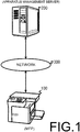
FIG. 1 is a diagram for describing an embodiment of an electronic apparatus according to the present invention. -
FIG. 2 is a diagram illustrating an example of a configuration of the MFP and the apparatus management server inFIG. 1 . -
FIG. 3 is a diagram for describing the basic contents of a data management table that is managed by the MFP inFIG. 1 . -
FIG. 4A is a diagram illustrating a data management table that is managed by the MFP inFIG. 1 , and illustrates the contents of the data management table at the time of startup. -
FIG. 4B is a diagram illustrating a data management table that is managed by the MFP inFIG. 1 , and illustrates the contents of the data management table when specific processing is executed. -
FIG. 4C is a diagram illustrating a data management table that is managed by the MFP inFIG. 1 , and illustrates the contents of the data management table at the time of data transmission. -
FIG. 5 is a flowchart for describing a process related to data acquisition by the MFP inFIG. 1 . - Hereinafter, an embodiment of an electronic apparatus according to the present invention will be described with reference to
FIG. 1 to FIG. 5 . Note that in the following description, a multifunction peripheral (MFP) that is a complex peripheral apparatus equipped with various functional units such as a print function, a copy function, a FAX function, a data transmission/reception function via a network and the like will be used, for example, as an example of an electronic apparatus. - First, as illustrated in
FIG. 1 , the MFP 100 is connected to anapparatus management server 200 via anetwork 300 such as the Internet or the like. Although the details will be described later, the MFP 100 manages status information of various functional units and the like, and transmits the status information in response to a request from theapparatus management server 200. It should be noted that the number ofMFPs 100 is not limited to one, and may be two or more. Theapparatus management server 200 periodically (for example, once a day (for example, 5:00 PM)) acquires various status information from theMFP 100 for maintenance management and the like of theMFP 100. Further, the timing of the request from theapparatus management server 200 may be arbitrarily changed. For example, it may be twice a day or once every two days. Also, the time is not limited to 5:00 PM but may be, for example, 8:00 AM or the like. - Next, an example of a configuration of the
MFP 100 and theapparatus management server 200 will be described with reference toFIG. 2 . First, the MFP 100 includes acontrol unit 110 that controls operations of an I/F 101, ascanner unit 102, aprinter unit 103, aFAX unit 104, apanel unit 105, and a hard disk drive (HDD) 106. The I/F 101 is responsible for communication with theapparatus management server 200 and the like via thenetwork 300. In addition, the I/F 101 is responsible for communication withother MFPs 100, user terminals (not illustrated), and the like. Note that the I/F 101 may also be responsible for communication with a content server, a web server and the like (that are not illustrated) via thenetwork 300. Thescanner unit 102 is a device that converts an image of a document (not illustrated) that is read by an image sensor (omitted in the figures) into digital image data and inputs the digital image data to thecontrol unit 110. Theprinter unit 103 is a device that prints an image on paper (not illustrated) based on print data that is outputted from thecontrol unit 110. TheFAX unit 104 is a device that transmits data that is outputted from thecontrol unit 110 to a facsimile of another party via a telephone line, and receives data from the facsimile of another party and inputs the data to thecontrol unit 110. Thepanel unit 105 is a device such as a touch panel or the like that performs a print function, a copy function, a FAX function, a data transmission/reception function via a network of theMFP 100, and performs displays for various settings of theMFP 100. The HDD 106 is a storage device that stores application programs and the like for providing various functions of theMFP 100. In addition, the HDD 106 has a user box for storing print jobs registered from a user terminal, for example. - The
control unit 110 is a processor that controls the overall operation of theMFP 100 by executing an application program for a print function, a copy function, a facsimile function, a data transmission/reception function via a network and the like, an image forming program, a control program, and the like. Thecontrol unit 110 includes ascanner control unit 111, aprinter control unit 112, a facsimile (FAX)control unit 113, acommunication control unit 114, a random access memory (RAM) 115, a read-only memory (ROM) 116, animage processing unit 117, a statusinformation managing unit 118, a paneloperation control unit 119, anHDD control unit 120, and asystem control unit 121. In addition, these units are connected to adata bus 122. - The
scanner control unit 111 controls the reading operation of thescanner unit 102. Theprinter control unit 112 controls the printing operation of theprinter unit 103. TheFAX control unit 113 controls the data transmission/reception operation by theFAX unit 104. Thecommunication control unit 114, via the I/F 101, controls transmission and reception of data and the like via thenetwork 300. - The
RAM 115 is a work memory for executing a program. In addition, theRAM 115 stores print data that has been subjected to image processing by theimage processing unit 117. TheROM 116 stores a control program for performing an operation check or the like of each unit. Theimage processing unit 117 performs image processing (rasterization) on image data that is read by thescanner unit 102. In addition, theimage processing unit 117 performs image processing (rasterization) on a print job registered in a user box of theHDD 106, for example. Note that thesystem control unit 121 causes theRAM 115 to temporarily store print data that has been subjected to image processing by theimage processing unit 117. - The status
information managing unit 118, as will be described in detail later, manages data indicating the status of each functional unit based on an instruction from thesystem control unit 121 and according to data management tables 130A to 130C illustrated inFIG. 4A to FIG. 4C described later. The paneloperation control unit 119 controls the display operation of thepanel unit 105. In addition, the paneloperation control unit 119, via thepanel unit 105, receives settings and the like for starting printing, copying, FAX, data transmission/reception via a network, and the like. TheHDD control unit 120 controls reading, writing and the like of data to and from theHDD 106. Thesystem control unit 121 controls the cooperative operation and the like of each unit. In addition, thesystem control unit 121 transmits status information that is managed by the statusinformation managing unit 118 to theapparatus management server 200 via thecommunication control unit 114 in response to a periodic (for example, once a day (for example, 5:00 PM)) request from theapparatus management server 200. - The
apparatus management server 200 includes an interface (I/F) 201 and acontrol unit 210 that controls theHDD 202. The I/F 201 is responsible for communication with theMFP 100 and the like via thenetwork 300. TheHDD 202 stores an application program for providing various functions of theapparatus management server 200, status information acquired from theMFP 100, and the like. - The
control unit 210 is a processor that controls the overall operation of theapparatus management server 200 by executing an application program, a control program, and the like. Thecontrol unit 210 includes a RAM 211, aROM 212, anapparatus managing unit 213, anHDD control unit 214, acommunication control unit 215, and asystem control unit 216. In addition, these units are connected to adata bus 217. The RAM 211 is a work memory for executing a program. TheROM 212 stores a control program for performing an operation check or the like of each unit. Theapparatus managing unit 213 manages the status information that is acquired from theMFP 100 in association with the apparatus identification information. Note that the status information is stored in theHDD 202. TheHDD control unit 214 controls reading, writing and the like of data to and from theHDD 202. Thecommunication control unit 215, via the I/F 201, controls transmission and reception of data and the like via thenetwork 300.System control unit 216 periodically (for example, once a day (for example, 5:00 PM)) acquires status information from theMFP 100. - Next, a basic configuration of the data management tables 130A to 130C in
FIG. 4A to FIG. 4C managed by the statusinformation managing unit 118 will be described with reference toFIG. 3 . The data management tables 130A to 130C will be described later. In other words, the data management table 130 inFIG. 3 includes anitem column 130a indicating an attribute code, anitem column 130b indicating change conditions, anitem column 130c indicating data management, anitem column 130d indicating acquired data items, and anitem column 130e indicating acquired values. - The attribute codes in the
item column 130a are indicated, for example, by A to C. The attribute code B is data (first data) that changes over time according to the usage status. The attribute codes A and C are data (second data) that do not change over time according to the usage status, and are data of a property having a lower degree of change compared with data (first data) corresponding to attribute code B. The change conditions initem column 130b are classified into three change states, for example, "no change", "changes over time", and "changes in specific processing". In other words, attribute code A indicates data (third data) having the property of "no change". Moreover, attribute code B indicates data (first data) having the property of "changes over time". Furthermore, the attribute code C indicates data (fourth data) having a property of "changes in specific processing". - The data management in the
item column 130c defines three management methods: "acquire and cache in advance", "acquire at transmission", and "acquire and cache in advance, and update in specific processing". In other words, the data of the attribute code A having the "no change" property is "acquire and cache in advance". Moreover, the data of the attribute code B having the property "changes over time" is "acquire at transmission". Furthermore, the data of the attribute code C having the property "changes in specific processing" is "acquire and cache in advance, and update in specific processing". - The acquired data items in
item column 130d indicate "serial number", "in-machine temperature", "print counter", "transfer voltage", and the like. The "serial number" or the like corresponds to data having the property "no change" of attribute code A. In addition, the "in-machine temperature" or the like corresponds to data having the property "changes over time" of attribute code B. Moreover, the "print counter", "transfer voltage", and the like corresponds to data having the property "changes in specific processing" of attribute code C. Note that the example of the acquireddata item 130d is merely an example, and represents a typical example. Furthermore, the values in theitem column 130e indicate the acquired data. In addition, the data included in the attribute codes A to C is stored in a nonvolatile storage device such as theHDD 106 or the like. Note that the data included in the attribute code B may be stored in a volatile storage device such as theRAM 115 or the like. - Next, an example of the data management tables 130A to 130C managed by the status
information managing unit 118 will be described with reference toFIG. 4A to FIG. 4C . First,FIG. 4A illustrates the data management table 130A at the time of startup of theMFP 100. Here, the time of startup is, for example, when theMFP 100 is in the power OFF mode and switches from the power OFF mode to the normal mode. Moreover, the time of startup may be when the power supply of theMFP 100 is in the OFF state (the main switch is "OFF") and a startup process is being executed to switch the power supply to the ON state (the main switch is "ON"). At the time of startup, the statusinformation managing unit 118 registers the data "serial number", "print counter", and "transfer voltage" illustrated in theitem column 130d in the data management table 130A illustrated inFIG. 4A . In other words, the statusinformation managing unit 118 acquires data corresponding to the attribute codes A and C at the time of startup, and stores the data in theHDD 106. In addition, the statusinformation managing unit 118 stores data indicating the "serial number" xyz1234567, the data indicating "print counter" 100 sheets, and the data indicating "transfer voltage" 50 V in theitem column 130e in theHDD 106, and at the same time, registers each of the data in theitem column 130e of the data management table 130A. Note that the "transfer voltage" may be acquired as a set value at the time of startup of theMFP 100. - Next,
FIG. 4B illustrates the data management table 130B at the time of executing specific processing. Here, the specific processing is processing such as a print function, a copy function, a FAX function, and a data transmission/reception function via a network and the like. At the time of executing specific processing, the statusinformation managing unit 118 updates the data of the "print counter" and "transfer voltage" of the data of the "serial number", "in-machine temperature", "print counter", and "transfer voltage" in theitem column 130d of the data management table 130B illustrated inFIG. 4B . In other words, at the time of executing a printing process, for example, the statusinformation managing unit 118 acquires the data of the "print counter" and the data of the "transfer voltage", updates the data of the "print counter" and the data of the "transfer voltage" that are stored in theHDD 106, and at the same time, updates the data in theitem column 130e of the data management table 130A. Here, for example, when the print function, the copy function, or the FAX function is used as the specific processing, the value of the "print counter" changes according to the printing process, so that the data of the "print counter" is updated according to the change. Note that in the case of the "transfer voltage", it is illustrated that the data of the "transfer voltage" is changed in accordance with a setting change or the like via thepanel unit 105. - Next,
FIG. 4C illustrates the data management table 130C at the time of data transmission. Here, the time of data transmission is a period until theMFP 100 transmits status information in response to a status information transmission request from theapparatus management server 200. At the time of data transmission, the statusinformation managing unit 118 acquires and registers the data of the "in-machine temperature" of the data of the "serial number", "in-machine temperature", "print counter", and "transfer voltage" data illustrated in theitem column 130d of the data management table 130C illustrated inFIG. 4C . In other words, the statusinformation managing unit 118 registers the "in-machine temperature" as 20 °C as illustrated in theitem column 130e. - Then, after receiving a status information request from the
apparatus management server 200, thesystem control unit 121 of theMFP 100 creates transmission data based on the data management table 130C at the time of data transmission managed by the statusinformation managing unit 118 and transmits the transmission data to theapparatus management server 200. - In addition, the data management definitions illustrated in the
item column 130c ofFIG. 4A to FIG. 4C may be arbitrarily changed. Furthermore, the contents of the acquired data items illustrated in theitem column 130d ofFIGS. 4A to 4C may be also arbitrarily changed. - Next, processing related to data acquisition by the
MFP 100 will be described with reference toFIG. 5 . Note that in the following, it is presumed that data corresponding to the attribute codes A and C illustrated inFIG. 4A to FIG. 4C are cached in theHDD 106. Moreover, in the following, it is presumed that theMFP 100 has switched to the power OFF mode. Furthermore, in the following, specific processing is presumed to be printing. - The
system control unit 121 determines whether or not there is an instruction to switch to the normal mode. - In this case, the
system control unit 121 determines that there is no instruction to shift to the normal mode unless there is a notification from the paneloperation control unit 119 via thepanel unit 105 that there is an instruction to shift to the normal mode (step S101: NO). - On the other hand, when there is a notification from the panel
operation control unit 119 via thepanel unit 105 indicating that there is an instruction to shift to the normal mode, thesystem control unit 121 determines there is an instruction to shift to the normal mode (step S101: YES), and proceeds to step S102. - The
system control unit 121 instructs the statusinformation managing unit 118 to cache the data of the attribute codes A and C. - At this time, the status
information managing unit 118, at the time of startup, acquires data corresponding to the attribute codes A and C in the data management table 130A, and stores the data in theHDD 106. In other words, the statusinformation managing unit 118 acquires data indicating "serial number" xyz1234567 corresponding to the attribute code A in theitem column 130e and stores the data in theHDD 106. In addition, the statusinformation managing unit 118 causes theHDD 106 to store data indicating the "print counter" 100 sheets and data indicating the "transfer voltage" 50 V corresponding to the attribute code C in theitem column 130e. Moreover, the statusinformation managing unit 118 stores the data corresponding to the attribute codes A and C in theHDD 106, and at the same time registers the respective data in theitem column 130e of the data management table 130A. - The
system control unit 121 determines whether or not specific processing has been instructed. - In this case, the
system control unit 121 determines that specific processing is not instructed unless there is a notification from the paneloperation control unit 119 via thepanel unit 105 indicating that there is a print instruction (step S103: NO). - On the other hand, the
system control unit 121 determines that specific processing is instructed when there is a notification from the paneloperation control unit 119 via thepanel unit 105 indicating that there is a print instruction (step S103: YES), and proceeds to step S104. - The
system control unit 121 determines whether or not the specific processing has been completed. - In this case, the
system control unit 121 determines that the specific processing has not been completed unless there is a notification from theprinter control unit 112 indicating the end of printing (step S104: NO). - On the other hand, when there is a notification from the
printer control unit 112 indicating the end of printing, thesystem control unit 121 determines that the specific processing is completed (step S104: YES), and proceeds to step S105. - The
system control unit 121 causes the statusinformation managing unit 118 to update the data of the attribute code C. - At this time, at the time of executing specific processing, the status
information managing unit 118, as illustrated inFIG. 4B , acquires data of the "print counter" and the "transfer voltage" corresponding to attribute code C of the data of the "serial number", "in-machine temperature", "print counter", and "transfer voltage" illustrated initem column 130d of the data management table 130B, and updates the data in theHDD 106, while at the same time, updates the data corresponding toitem column 130d. In other words, the statusinformation managing unit 118 updates the data of the "print counter" to, for example, 105 sheets, and updates the data of the "transfer voltage" to 60 V, as illustrated in theitem column 130e. - The
system control unit 121 determines whether or not there is a status information transmission request from theapparatus management server 200. - In this case, the
system control unit 121 determines that there is no status information transmission request from theapparatus management server 200 unless there is a notification from thecommunication control unit 114 indicating that there is a status information transmission request from the apparatus management server 200 (step S106: NO). - On the other hand, when there is a notification from the
communication control unit 114 indicating that there is a status information transmission request from theapparatus management server 200, thesystem control unit 121 determines that there is a status information transmission request from the apparatus management server 200 (step S106: YES), and proceeds to step S107). - The
system control unit 121 causes the statusinformation managing unit 118 to acquire the data of the attribute code B. - At this time, at the time of data transmission, as illustrated in
FIG. 4C , the statusinformation managing unit 118 acquires and registers the data of the "in-machine temperature" of the data of the "serial number", "in-machine temperature", "print counter", and "transfer voltage" illustrated in theitem column 130d of the data management table 130C. In other words, the statusinformation managing unit 118 acquires the data of "in-machine temperature" and registers the "in-machine temperature" illustrated in theitem column 130e as 20 ° C. - The
system control unit 121 determines whether or not data registration by the statusinformation managing unit 118 is completed. - In this case, the
system control unit 121 determines that data registration has not been completed unless there is a notification from the statusinformation managing unit 118 indicating that data registration has been completed for the data management table 130C (step S108: NO). - On the other hand, the
system control unit 121 determines that the data registration has been completed when there is a notification from the statusinformation managing unit 118 indicating that data registration has been completed for the data management table 130C (step S108: YES), and proceeds to step S109. - The
system control unit 121 transmits the status information to theapparatus management server 200. - In this case, the
system control unit 121 creates data indicating status information for transmission based on the data management table 130C at the time of data transmission managed by the statusinformation managing unit 118, and transmits the data to theapparatus management server 200. - In addition, in step S105, it is possible to predict that the degree of change is high for data relating to a function having a high execution frequency of the specific processing. Therefore, for data relating to a function having an execution frequency of the specific processing that is equal to or greater than a threshold value (for example, one time per minute), the cache in the
HDD 106 may be omitted, and the data may be acquired at the time of data transmission as in the case of data corresponding to the attribute code B. In particular, for data related to a function that repeatedly executes processing in a short time, it is preferable to acquire data at the time of data transmission in order to avoid repeated updates. - Moreover, at the time of startup in step S102, the status
information managing unit 118 acquires data corresponding to the attribute codes A and C of the data management table 130A; however, the data acquisition timing in this case may be set arbitrarily. In other words, at the time of startup, data corresponding to the attribute codes A and C may be divided and sequentially acquired. Furthermore, for example, it is possible to wait a specific amount of time (for example, 10 seconds) after the startup processing is complete, and after that specific amount of time has elapsed, data corresponding to the attribute codes A and C may be acquired collectively or dividedly. As a result, it is possible to reduce the load caused by the startup process and the data acquisition process. - As described above, in the present embodiment, the status
information managing unit 118 acquires data indicating the status of each functional unit to be transmitted to theapparatus management server 200, and thesystem control unit 121 instructs the data acquisition timing to the statusinformation managing unit 118. Moreover, the statusinformation managing unit 118 acquires the data of the attribute code B (data that changes over time according to the usage status) at the time of data transmission to theapparatus management server 200, and acquires and caches the data of the attribute codes A and C (the data that does not change over time according to the usage status) in advance. Furthermore, after receiving a transmission request from theapparatus management server 200, thesystem control unit 121 transmits status information including data cached by the statusinformation managing unit 118 and data acquired at the time of data transmission. - Thus, at the time of data transmission, only the data of the attribute code B (data that changes over time) needs to be acquired, so that the number of data to be acquired may be reduced, and the load on the system may be reduced.
- Note that in the present embodiment, the electronic apparatus is an
MFP 100, however the present invention may also be applied to other image forming apparatuses such as a multifunction printer or the like.
Claims (2)
- An electronic apparatus, characterized in that includes:a status information managing unit (118) that acquires and manages data indicating status of each functional unit for transmission to an apparatus management server (200); anda system control unit (121) that instructs acquisition timing for acquiring the data to the status information managing unit; whereinthe status information managing unitacquires first data that changes over time according to usage status at the time of data transmission to the apparatus management server; and acquires and caches in advance second data that does not change over time according to the usage status; andthe system control unit, after receiving a transmission request from the apparatus management server, transmits status information including the first data acquired at the time of data transmission, and the second data that is cached by the status information managing unit.
- The electronic apparatus according to claim 1, further characterized in that includes
a storage device; and wherein
the second data is third data having a property that does not change and fourth data having a property that changes in specific processing;
the system control unit, at each a time of startup, a time of executing specific processing, and the time of data transmission, instructs data acquisition timing for acquiring the data to the status information managing unit;
the status information managing unit
at the time of the startup, caches the third data and the fourth data in the storage device;
at the time of executing specific processing, updates the fourth data; and
at the time of data transmission, acquires the first data; and
the system control unit, at the time of data transmission, transmits the first data, the third data, and the fourth data that are managed, as the status information.
Applications Claiming Priority (2)
| Application Number | Priority Date | Filing Date | Title |
|---|---|---|---|
| JP2017183909 | 2017-09-25 | ||
| PCT/JP2018/022820 WO2019058663A1 (en) | 2017-09-25 | 2018-06-15 | Electronic device |
Publications (3)
| Publication Number | Publication Date |
|---|---|
| EP3689629A1 true EP3689629A1 (en) | 2020-08-05 |
| EP3689629A4 EP3689629A4 (en) | 2021-06-30 |
| EP3689629B1 EP3689629B1 (en) | 2024-06-12 |
Family
ID=65809726
Family Applications (1)
| Application Number | Title | Priority Date | Filing Date |
|---|---|---|---|
| EP18857938.7A Active EP3689629B1 (en) | 2017-09-25 | 2018-06-15 | Electronic device |
Country Status (5)
| Country | Link |
|---|---|
| US (1) | US11029898B2 (en) |
| EP (1) | EP3689629B1 (en) |
| JP (1) | JP6844709B2 (en) |
| CN (1) | CN111094004B (en) |
| WO (1) | WO2019058663A1 (en) |
Family Cites Families (20)
| Publication number | Priority date | Publication date | Assignee | Title |
|---|---|---|---|---|
| DE69636707T2 (en) * | 1995-02-09 | 2007-09-13 | Canon K.K. | Printer system, data processing device and data processing method |
| US6611347B1 (en) * | 1996-12-20 | 2003-08-26 | Canon Kabushiki Kaisha | Print control apparatus, print control method, storage medium, and computer readable program performing a form overlay process |
| JP3957998B2 (en) | 2000-08-08 | 2007-08-15 | キヤノン株式会社 | Printing system, image processing apparatus, and information processing apparatus |
| JP2002132470A (en) * | 2000-10-20 | 2002-05-10 | Canon Inc | Server device, font information management method, and storage medium |
| JP4566679B2 (en) * | 2003-11-13 | 2010-10-20 | キヤノン株式会社 | Image forming apparatus, control method, and program |
| JP2005309847A (en) * | 2004-04-22 | 2005-11-04 | Sharp Corp | Data processor |
| JP4978388B2 (en) * | 2007-09-11 | 2012-07-18 | コニカミノルタビジネステクノロジーズ株式会社 | Management system, management method, and management program |
| JP2009199253A (en) * | 2008-02-20 | 2009-09-03 | Canon Inc | Printing system, print method, and printer |
| JP2010010825A (en) * | 2008-06-24 | 2010-01-14 | Ricoh Co Ltd | Image-forming device, state management system of image-forming device, and state discrimination method |
| US9781148B2 (en) * | 2008-10-21 | 2017-10-03 | Lookout, Inc. | Methods and systems for sharing risk responses between collections of mobile communications devices |
| JP5665590B2 (en) * | 2010-04-28 | 2015-02-04 | キヤノン株式会社 | Printing system, client, control method, and program |
| US9158479B2 (en) * | 2010-10-01 | 2015-10-13 | Electronics For Imaging, Inc. | Automated printer's dashboard |
| JP5936366B2 (en) * | 2012-01-19 | 2016-06-22 | キヤノン株式会社 | Printing system, image forming apparatus, intermediate processing apparatus, web service providing apparatus, printing system control method, and computer program |
| US9009764B2 (en) * | 2012-04-12 | 2015-04-14 | Qualcomm Incorporated | Broadcast content via over the top delivery |
| JP2014059357A (en) * | 2012-09-14 | 2014-04-03 | Oki Data Corp | Management server, management method, management program, printer driver program, image forming apparatus, and image forming system |
| CN108646992B (en) * | 2013-11-07 | 2021-06-08 | 精工爱普生株式会社 | print control system |
| JP6217604B2 (en) * | 2014-11-21 | 2017-10-25 | コニカミノルタ株式会社 | Communication system, communication method, device with gateway function, and program |
| JP6476923B2 (en) * | 2015-01-30 | 2019-03-06 | 富士ゼロックス株式会社 | Device management system, management device, and program |
| JP6225960B2 (en) * | 2015-08-18 | 2017-11-08 | コニカミノルタ株式会社 | Network system, load suppression control program, and load suppression control method |
| JP7005139B2 (en) * | 2016-03-11 | 2022-01-21 | キヤノン株式会社 | Image processing device and its control method, printing system, program |
-
2018
- 2018-06-15 US US16/650,818 patent/US11029898B2/en active Active
- 2018-06-15 CN CN201880056830.2A patent/CN111094004B/en not_active Expired - Fee Related
- 2018-06-15 WO PCT/JP2018/022820 patent/WO2019058663A1/en not_active Ceased
- 2018-06-15 JP JP2019543413A patent/JP6844709B2/en active Active
- 2018-06-15 EP EP18857938.7A patent/EP3689629B1/en active Active
Also Published As
| Publication number | Publication date |
|---|---|
| CN111094004B (en) | 2021-10-26 |
| US11029898B2 (en) | 2021-06-08 |
| JP6844709B2 (en) | 2021-03-17 |
| CN111094004A (en) | 2020-05-01 |
| JPWO2019058663A1 (en) | 2020-11-05 |
| EP3689629B1 (en) | 2024-06-12 |
| WO2019058663A1 (en) | 2019-03-28 |
| US20200264816A1 (en) | 2020-08-20 |
| EP3689629A4 (en) | 2021-06-30 |
Similar Documents
| Publication | Publication Date | Title |
|---|---|---|
| JP5843637B2 (en) | Image forming apparatus, image forming apparatus control method, and program | |
| US8543677B2 (en) | Communication control device, method, and computer readable medium allowing an information processing device to be in a power saving mode for an extended period and allowing an application part to continue functioning | |
| US8934126B1 (en) | Image processing controller for performing image processing in cooperation with image forming apparatus, image forming system including image processing controller, method of controlling image forming system, and storage medium | |
| JP6337574B2 (en) | Processing execution system, relay server, and device | |
| US10469676B2 (en) | Image forming systems, and methods of using same | |
| EP3557403A1 (en) | Image forming system and image forming method | |
| US10382302B2 (en) | Electronic apparatus and non-transitory computer readable recording medium suitable for acquiring status information | |
| JP4978388B2 (en) | Management system, management method, and management program | |
| JP2016218706A (en) | Information distribution system, information distribution method, and electronic device | |
| CN102316240B (en) | Image forming apparatus, control method, and control apparatus | |
| JP5035257B2 (en) | Image output apparatus and image output system | |
| JP2015097080A (en) | Image forming apparatus management apparatus and management program | |
| EP3689629B1 (en) | Electronic device | |
| JP5866276B2 (en) | Power management system | |
| JP2005309893A (en) | Management system, its management center, and communication server | |
| US10956090B2 (en) | Memory system and electronic apparatus | |
| JP2008077209A (en) | Device management method and device management system | |
| JP2018128794A (en) | Job processor | |
| JP2005271307A (en) | Image forming apparatus and apparatus information output method therefor | |
| JP2020031307A (en) | Electronic equipment and memory management program | |
| JP2014123281A (en) | Information processing device, method for controlling the same, and program | |
| JP2020057960A (en) | Electronic apparatus and memory management program | |
| JP2010231334A (en) | Electronic apparatus and image forming system |
Legal Events
| Date | Code | Title | Description |
|---|---|---|---|
| STAA | Information on the status of an ep patent application or granted ep patent |
Free format text: STATUS: THE INTERNATIONAL PUBLICATION HAS BEEN MADE |
|
| PUAI | Public reference made under article 153(3) epc to a published international application that has entered the european phase |
Free format text: ORIGINAL CODE: 0009012 |
|
| STAA | Information on the status of an ep patent application or granted ep patent |
Free format text: STATUS: REQUEST FOR EXAMINATION WAS MADE |
|
| 17P | Request for examination filed |
Effective date: 20200320 |
|
| AK | Designated contracting states |
Kind code of ref document: A1 Designated state(s): AL AT BE BG CH CY CZ DE DK EE ES FI FR GB GR HR HU IE IS IT LI LT LU LV MC MK MT NL NO PL PT RO RS SE SI SK SM TR |
|
| AX | Request for extension of the european patent |
Extension state: BA ME |
|
| DAV | Request for validation of the european patent (deleted) | ||
| DAX | Request for extension of the european patent (deleted) | ||
| A4 | Supplementary search report drawn up and despatched |
Effective date: 20210531 |
|
| RIC1 | Information provided on ipc code assigned before grant |
Ipc: B41J 29/38 20060101AFI20210525BHEP Ipc: G06F 13/00 20060101ALI20210525BHEP Ipc: H04N 1/00 20060101ALI20210525BHEP Ipc: G06F 3/12 20060101ALI20210525BHEP Ipc: G06F 11/30 20060101ALI20210525BHEP |
|
| P01 | Opt-out of the competence of the unified patent court (upc) registered |
Effective date: 20230420 |
|
| REG | Reference to a national code |
Ref country code: DE Ref legal event code: R079 Free format text: PREVIOUS MAIN CLASS: B41J0029380000 Ipc: G06F0003120000 Ref document number: 602018070620 Country of ref document: DE |
|
| GRAP | Despatch of communication of intention to grant a patent |
Free format text: ORIGINAL CODE: EPIDOSNIGR1 |
|
| STAA | Information on the status of an ep patent application or granted ep patent |
Free format text: STATUS: GRANT OF PATENT IS INTENDED |
|
| RIC1 | Information provided on ipc code assigned before grant |
Ipc: G06F 13/00 20060101ALN20231214BHEP Ipc: G06F 11/34 20060101ALN20231214BHEP Ipc: H04N 1/00 20060101ALI20231214BHEP Ipc: B41J 29/38 20060101ALI20231214BHEP Ipc: G06F 11/30 20060101ALI20231214BHEP Ipc: G06F 3/12 20060101AFI20231214BHEP |
|
| INTG | Intention to grant announced |
Effective date: 20240104 |
|
| GRAS | Grant fee paid |
Free format text: ORIGINAL CODE: EPIDOSNIGR3 |
|
| GRAA | (expected) grant |
Free format text: ORIGINAL CODE: 0009210 |
|
| STAA | Information on the status of an ep patent application or granted ep patent |
Free format text: STATUS: THE PATENT HAS BEEN GRANTED |
|
| AK | Designated contracting states |
Kind code of ref document: B1 Designated state(s): AL AT BE BG CH CY CZ DE DK EE ES FI FR GB GR HR HU IE IS IT LI LT LU LV MC MK MT NL NO PL PT RO RS SE SI SK SM TR |
|
| REG | Reference to a national code |
Ref country code: GB Ref legal event code: FG4D |
|
| REG | Reference to a national code |
Ref country code: CH Ref legal event code: EP |
|
| REG | Reference to a national code |
Ref country code: IE Ref legal event code: FG4D |
|
| REG | Reference to a national code |
Ref country code: DE Ref legal event code: R096 Ref document number: 602018070620 Country of ref document: DE |
|
| PG25 | Lapsed in a contracting state [announced via postgrant information from national office to epo] |
Ref country code: BG Free format text: LAPSE BECAUSE OF FAILURE TO SUBMIT A TRANSLATION OF THE DESCRIPTION OR TO PAY THE FEE WITHIN THE PRESCRIBED TIME-LIMIT Effective date: 20240612 |
|
| PG25 | Lapsed in a contracting state [announced via postgrant information from national office to epo] |
Ref country code: FI Free format text: LAPSE BECAUSE OF FAILURE TO SUBMIT A TRANSLATION OF THE DESCRIPTION OR TO PAY THE FEE WITHIN THE PRESCRIBED TIME-LIMIT Effective date: 20240612 Ref country code: HR Free format text: LAPSE BECAUSE OF FAILURE TO SUBMIT A TRANSLATION OF THE DESCRIPTION OR TO PAY THE FEE WITHIN THE PRESCRIBED TIME-LIMIT Effective date: 20240612 |
|
| REG | Reference to a national code |
Ref country code: LT Ref legal event code: MG9D |
|
| PG25 | Lapsed in a contracting state [announced via postgrant information from national office to epo] |
Ref country code: GR Free format text: LAPSE BECAUSE OF FAILURE TO SUBMIT A TRANSLATION OF THE DESCRIPTION OR TO PAY THE FEE WITHIN THE PRESCRIBED TIME-LIMIT Effective date: 20240913 |
|
| REG | Reference to a national code |
Ref country code: NL Ref legal event code: MP Effective date: 20240612 |
|
| PG25 | Lapsed in a contracting state [announced via postgrant information from national office to epo] |
Ref country code: ES Free format text: LAPSE BECAUSE OF FAILURE TO SUBMIT A TRANSLATION OF THE DESCRIPTION OR TO PAY THE FEE WITHIN THE PRESCRIBED TIME-LIMIT Effective date: 20240612 |
|
| PG25 | Lapsed in a contracting state [announced via postgrant information from national office to epo] |
Ref country code: LV Free format text: LAPSE BECAUSE OF FAILURE TO SUBMIT A TRANSLATION OF THE DESCRIPTION OR TO PAY THE FEE WITHIN THE PRESCRIBED TIME-LIMIT Effective date: 20240612 |
|
| PG25 | Lapsed in a contracting state [announced via postgrant information from national office to epo] |
Ref country code: NO Free format text: LAPSE BECAUSE OF FAILURE TO SUBMIT A TRANSLATION OF THE DESCRIPTION OR TO PAY THE FEE WITHIN THE PRESCRIBED TIME-LIMIT Effective date: 20240912 Ref country code: LV Free format text: LAPSE BECAUSE OF FAILURE TO SUBMIT A TRANSLATION OF THE DESCRIPTION OR TO PAY THE FEE WITHIN THE PRESCRIBED TIME-LIMIT Effective date: 20240612 Ref country code: HR Free format text: LAPSE BECAUSE OF FAILURE TO SUBMIT A TRANSLATION OF THE DESCRIPTION OR TO PAY THE FEE WITHIN THE PRESCRIBED TIME-LIMIT Effective date: 20240612 Ref country code: GR Free format text: LAPSE BECAUSE OF FAILURE TO SUBMIT A TRANSLATION OF THE DESCRIPTION OR TO PAY THE FEE WITHIN THE PRESCRIBED TIME-LIMIT Effective date: 20240913 Ref country code: FI Free format text: LAPSE BECAUSE OF FAILURE TO SUBMIT A TRANSLATION OF THE DESCRIPTION OR TO PAY THE FEE WITHIN THE PRESCRIBED TIME-LIMIT Effective date: 20240612 Ref country code: ES Free format text: LAPSE BECAUSE OF FAILURE TO SUBMIT A TRANSLATION OF THE DESCRIPTION OR TO PAY THE FEE WITHIN THE PRESCRIBED TIME-LIMIT Effective date: 20240612 Ref country code: BG Free format text: LAPSE BECAUSE OF FAILURE TO SUBMIT A TRANSLATION OF THE DESCRIPTION OR TO PAY THE FEE WITHIN THE PRESCRIBED TIME-LIMIT Effective date: 20240612 Ref country code: RS Free format text: LAPSE BECAUSE OF FAILURE TO SUBMIT A TRANSLATION OF THE DESCRIPTION OR TO PAY THE FEE WITHIN THE PRESCRIBED TIME-LIMIT Effective date: 20240912 |
|
| PG25 | Lapsed in a contracting state [announced via postgrant information from national office to epo] |
Ref country code: NL Free format text: LAPSE BECAUSE OF FAILURE TO SUBMIT A TRANSLATION OF THE DESCRIPTION OR TO PAY THE FEE WITHIN THE PRESCRIBED TIME-LIMIT Effective date: 20240612 |
|
| REG | Reference to a national code |
Ref country code: AT Ref legal event code: MK05 Ref document number: 1694798 Country of ref document: AT Kind code of ref document: T Effective date: 20240612 |
|
| PG25 | Lapsed in a contracting state [announced via postgrant information from national office to epo] |
Ref country code: NL Free format text: LAPSE BECAUSE OF FAILURE TO SUBMIT A TRANSLATION OF THE DESCRIPTION OR TO PAY THE FEE WITHIN THE PRESCRIBED TIME-LIMIT Effective date: 20240612 |
|
| PG25 | Lapsed in a contracting state [announced via postgrant information from national office to epo] |
Ref country code: PT Free format text: LAPSE BECAUSE OF FAILURE TO SUBMIT A TRANSLATION OF THE DESCRIPTION OR TO PAY THE FEE WITHIN THE PRESCRIBED TIME-LIMIT Effective date: 20241014 |
|
| PG25 | Lapsed in a contracting state [announced via postgrant information from national office to epo] |
Ref country code: PT Free format text: LAPSE BECAUSE OF FAILURE TO SUBMIT A TRANSLATION OF THE DESCRIPTION OR TO PAY THE FEE WITHIN THE PRESCRIBED TIME-LIMIT Effective date: 20241014 |
|
| PG25 | Lapsed in a contracting state [announced via postgrant information from national office to epo] |
Ref country code: PL Free format text: LAPSE BECAUSE OF FAILURE TO SUBMIT A TRANSLATION OF THE DESCRIPTION OR TO PAY THE FEE WITHIN THE PRESCRIBED TIME-LIMIT Effective date: 20240612 |
|
| PG25 | Lapsed in a contracting state [announced via postgrant information from national office to epo] |
Ref country code: EE Free format text: LAPSE BECAUSE OF FAILURE TO SUBMIT A TRANSLATION OF THE DESCRIPTION OR TO PAY THE FEE WITHIN THE PRESCRIBED TIME-LIMIT Effective date: 20240612 |
|
| PG25 | Lapsed in a contracting state [announced via postgrant information from national office to epo] |
Ref country code: AT Free format text: LAPSE BECAUSE OF FAILURE TO SUBMIT A TRANSLATION OF THE DESCRIPTION OR TO PAY THE FEE WITHIN THE PRESCRIBED TIME-LIMIT Effective date: 20240612 Ref country code: IS Free format text: LAPSE BECAUSE OF FAILURE TO SUBMIT A TRANSLATION OF THE DESCRIPTION OR TO PAY THE FEE WITHIN THE PRESCRIBED TIME-LIMIT Effective date: 20241012 |
|
| PG25 | Lapsed in a contracting state [announced via postgrant information from national office to epo] |
Ref country code: CZ Free format text: LAPSE BECAUSE OF FAILURE TO SUBMIT A TRANSLATION OF THE DESCRIPTION OR TO PAY THE FEE WITHIN THE PRESCRIBED TIME-LIMIT Effective date: 20240612 |
|
| PG25 | Lapsed in a contracting state [announced via postgrant information from national office to epo] |
Ref country code: SK Free format text: LAPSE BECAUSE OF FAILURE TO SUBMIT A TRANSLATION OF THE DESCRIPTION OR TO PAY THE FEE WITHIN THE PRESCRIBED TIME-LIMIT Effective date: 20240612 Ref country code: RO Free format text: LAPSE BECAUSE OF FAILURE TO SUBMIT A TRANSLATION OF THE DESCRIPTION OR TO PAY THE FEE WITHIN THE PRESCRIBED TIME-LIMIT Effective date: 20240612 |
|
| PG25 | Lapsed in a contracting state [announced via postgrant information from national office to epo] |
Ref country code: SM Free format text: LAPSE BECAUSE OF FAILURE TO SUBMIT A TRANSLATION OF THE DESCRIPTION OR TO PAY THE FEE WITHIN THE PRESCRIBED TIME-LIMIT Effective date: 20240612 |
|
| PG25 | Lapsed in a contracting state [announced via postgrant information from national office to epo] |
Ref country code: SM Free format text: LAPSE BECAUSE OF FAILURE TO SUBMIT A TRANSLATION OF THE DESCRIPTION OR TO PAY THE FEE WITHIN THE PRESCRIBED TIME-LIMIT Effective date: 20240612 Ref country code: SK Free format text: LAPSE BECAUSE OF FAILURE TO SUBMIT A TRANSLATION OF THE DESCRIPTION OR TO PAY THE FEE WITHIN THE PRESCRIBED TIME-LIMIT Effective date: 20240612 Ref country code: RO Free format text: LAPSE BECAUSE OF FAILURE TO SUBMIT A TRANSLATION OF THE DESCRIPTION OR TO PAY THE FEE WITHIN THE PRESCRIBED TIME-LIMIT Effective date: 20240612 Ref country code: PL Free format text: LAPSE BECAUSE OF FAILURE TO SUBMIT A TRANSLATION OF THE DESCRIPTION OR TO PAY THE FEE WITHIN THE PRESCRIBED TIME-LIMIT Effective date: 20240612 Ref country code: IS Free format text: LAPSE BECAUSE OF FAILURE TO SUBMIT A TRANSLATION OF THE DESCRIPTION OR TO PAY THE FEE WITHIN THE PRESCRIBED TIME-LIMIT Effective date: 20241012 Ref country code: EE Free format text: LAPSE BECAUSE OF FAILURE TO SUBMIT A TRANSLATION OF THE DESCRIPTION OR TO PAY THE FEE WITHIN THE PRESCRIBED TIME-LIMIT Effective date: 20240612 Ref country code: CZ Free format text: LAPSE BECAUSE OF FAILURE TO SUBMIT A TRANSLATION OF THE DESCRIPTION OR TO PAY THE FEE WITHIN THE PRESCRIBED TIME-LIMIT Effective date: 20240612 Ref country code: AT Free format text: LAPSE BECAUSE OF FAILURE TO SUBMIT A TRANSLATION OF THE DESCRIPTION OR TO PAY THE FEE WITHIN THE PRESCRIBED TIME-LIMIT Effective date: 20240612 |
|
| REG | Reference to a national code |
Ref country code: CH Ref legal event code: PL |
|
| PG25 | Lapsed in a contracting state [announced via postgrant information from national office to epo] |
Ref country code: IT Free format text: LAPSE BECAUSE OF FAILURE TO SUBMIT A TRANSLATION OF THE DESCRIPTION OR TO PAY THE FEE WITHIN THE PRESCRIBED TIME-LIMIT Effective date: 20240612 |
|
| PG25 | Lapsed in a contracting state [announced via postgrant information from national office to epo] |
Ref country code: LU Free format text: LAPSE BECAUSE OF NON-PAYMENT OF DUE FEES Effective date: 20240615 |
|
| REG | Reference to a national code |
Ref country code: DE Ref legal event code: R097 Ref document number: 602018070620 Country of ref document: DE |
|
| PG25 | Lapsed in a contracting state [announced via postgrant information from national office to epo] |
Ref country code: MC Free format text: LAPSE BECAUSE OF FAILURE TO SUBMIT A TRANSLATION OF THE DESCRIPTION OR TO PAY THE FEE WITHIN THE PRESCRIBED TIME-LIMIT Effective date: 20240612 |
|
| PG25 | Lapsed in a contracting state [announced via postgrant information from national office to epo] |
Ref country code: MC Free format text: LAPSE BECAUSE OF FAILURE TO SUBMIT A TRANSLATION OF THE DESCRIPTION OR TO PAY THE FEE WITHIN THE PRESCRIBED TIME-LIMIT Effective date: 20240612 |
|
| PG25 | Lapsed in a contracting state [announced via postgrant information from national office to epo] |
Ref country code: DK Free format text: LAPSE BECAUSE OF FAILURE TO SUBMIT A TRANSLATION OF THE DESCRIPTION OR TO PAY THE FEE WITHIN THE PRESCRIBED TIME-LIMIT Effective date: 20240612 |
|
| PLBE | No opposition filed within time limit |
Free format text: ORIGINAL CODE: 0009261 |
|
| STAA | Information on the status of an ep patent application or granted ep patent |
Free format text: STATUS: NO OPPOSITION FILED WITHIN TIME LIMIT |
|
| PG25 | Lapsed in a contracting state [announced via postgrant information from national office to epo] |
Ref country code: IE Free format text: LAPSE BECAUSE OF NON-PAYMENT OF DUE FEES Effective date: 20240615 |
|
| PG25 | Lapsed in a contracting state [announced via postgrant information from national office to epo] |
Ref country code: BE Free format text: LAPSE BECAUSE OF NON-PAYMENT OF DUE FEES Effective date: 20240630 Ref country code: CH Free format text: LAPSE BECAUSE OF NON-PAYMENT OF DUE FEES Effective date: 20240630 |
|
| REG | Reference to a national code |
Ref country code: BE Ref legal event code: MM Effective date: 20240630 |
|
| 26N | No opposition filed |
Effective date: 20250313 |
|
| GBPC | Gb: european patent ceased through non-payment of renewal fee |
Effective date: 20240912 |
|
| PG25 | Lapsed in a contracting state [announced via postgrant information from national office to epo] |
Ref country code: GB Free format text: LAPSE BECAUSE OF NON-PAYMENT OF DUE FEES Effective date: 20240912 |
|
| PG25 | Lapsed in a contracting state [announced via postgrant information from national office to epo] |
Ref country code: FR Free format text: LAPSE BECAUSE OF NON-PAYMENT OF DUE FEES Effective date: 20240812 |
|
| PG25 | Lapsed in a contracting state [announced via postgrant information from national office to epo] |
Ref country code: SE Free format text: LAPSE BECAUSE OF FAILURE TO SUBMIT A TRANSLATION OF THE DESCRIPTION OR TO PAY THE FEE WITHIN THE PRESCRIBED TIME-LIMIT Effective date: 20240612 |
|
| PG25 | Lapsed in a contracting state [announced via postgrant information from national office to epo] |
Ref country code: CY Free format text: LAPSE BECAUSE OF FAILURE TO SUBMIT A TRANSLATION OF THE DESCRIPTION OR TO PAY THE FEE WITHIN THE PRESCRIBED TIME-LIMIT; INVALID AB INITIO Effective date: 20180615 |
|
| PG25 | Lapsed in a contracting state [announced via postgrant information from national office to epo] |
Ref country code: HU Free format text: LAPSE BECAUSE OF FAILURE TO SUBMIT A TRANSLATION OF THE DESCRIPTION OR TO PAY THE FEE WITHIN THE PRESCRIBED TIME-LIMIT; INVALID AB INITIO Effective date: 20180615 |
|
| PG25 | Lapsed in a contracting state [announced via postgrant information from national office to epo] |
Ref country code: TR Free format text: LAPSE BECAUSE OF FAILURE TO SUBMIT A TRANSLATION OF THE DESCRIPTION OR TO PAY THE FEE WITHIN THE PRESCRIBED TIME-LIMIT Effective date: 20240612 |
|
| PG25 | Lapsed in a contracting state [announced via postgrant information from national office to epo] |
Ref country code: SI Free format text: LAPSE BECAUSE OF FAILURE TO SUBMIT A TRANSLATION OF THE DESCRIPTION OR TO PAY THE FEE WITHIN THE PRESCRIBED TIME-LIMIT Effective date: 20240612 |
|
| PG25 | Lapsed in a contracting state [announced via postgrant information from national office to epo] |
Ref country code: LT Free format text: LAPSE BECAUSE OF FAILURE TO SUBMIT A TRANSLATION OF THE DESCRIPTION OR TO PAY THE FEE WITHIN THE PRESCRIBED TIME-LIMIT Effective date: 20240612 |
|
| PGFP | Annual fee paid to national office [announced via postgrant information from national office to epo] |
Ref country code: DE Payment date: 20260520 Year of fee payment: 9 |