EP3689573A1 - A set of hinged components produced by multi-material injection molding - Google Patents
A set of hinged components produced by multi-material injection molding Download PDFInfo
- Publication number
- EP3689573A1 EP3689573A1 EP20154754.4A EP20154754A EP3689573A1 EP 3689573 A1 EP3689573 A1 EP 3689573A1 EP 20154754 A EP20154754 A EP 20154754A EP 3689573 A1 EP3689573 A1 EP 3689573A1
- Authority
- EP
- European Patent Office
- Prior art keywords
- component
- mold
- plastic material
- hole
- molding
- Prior art date
- Legal status (The legal status is an assumption and is not a legal conclusion. Google has not performed a legal analysis and makes no representation as to the accuracy of the status listed.)
- Granted
Links
Images






Classifications
-
- B—PERFORMING OPERATIONS; TRANSPORTING
- B29—WORKING OF PLASTICS; WORKING OF SUBSTANCES IN A PLASTIC STATE IN GENERAL
- B29C—SHAPING OR JOINING OF PLASTICS; SHAPING OF MATERIAL IN A PLASTIC STATE, NOT OTHERWISE PROVIDED FOR; AFTER-TREATMENT OF THE SHAPED PRODUCTS, e.g. REPAIRING
- B29C45/00—Injection moulding, i.e. forcing the required volume of moulding material through a nozzle into a closed mould; Apparatus therefor
- B29C45/0017—Injection moulding, i.e. forcing the required volume of moulding material through a nozzle into a closed mould; Apparatus therefor moulding interconnected elements which are movable with respect to one another, e.g. chains or hinges
-
- B—PERFORMING OPERATIONS; TRANSPORTING
- B29—WORKING OF PLASTICS; WORKING OF SUBSTANCES IN A PLASTIC STATE IN GENERAL
- B29C—SHAPING OR JOINING OF PLASTICS; SHAPING OF MATERIAL IN A PLASTIC STATE, NOT OTHERWISE PROVIDED FOR; AFTER-TREATMENT OF THE SHAPED PRODUCTS, e.g. REPAIRING
- B29C45/00—Injection moulding, i.e. forcing the required volume of moulding material through a nozzle into a closed mould; Apparatus therefor
- B29C45/16—Making multilayered or multicoloured articles
- B29C45/1615—The materials being injected at different moulding stations
-
- B—PERFORMING OPERATIONS; TRANSPORTING
- B29—WORKING OF PLASTICS; WORKING OF SUBSTANCES IN A PLASTIC STATE IN GENERAL
- B29C—SHAPING OR JOINING OF PLASTICS; SHAPING OF MATERIAL IN A PLASTIC STATE, NOT OTHERWISE PROVIDED FOR; AFTER-TREATMENT OF THE SHAPED PRODUCTS, e.g. REPAIRING
- B29C45/00—Injection moulding, i.e. forcing the required volume of moulding material through a nozzle into a closed mould; Apparatus therefor
- B29C45/16—Making multilayered or multicoloured articles
- B29C45/1615—The materials being injected at different moulding stations
- B29C45/162—The materials being injected at different moulding stations using means, e.g. mould parts, for transferring an injected part between moulding stations
-
- B—PERFORMING OPERATIONS; TRANSPORTING
- B29—WORKING OF PLASTICS; WORKING OF SUBSTANCES IN A PLASTIC STATE IN GENERAL
- B29C—SHAPING OR JOINING OF PLASTICS; SHAPING OF MATERIAL IN A PLASTIC STATE, NOT OTHERWISE PROVIDED FOR; AFTER-TREATMENT OF THE SHAPED PRODUCTS, e.g. REPAIRING
- B29C45/00—Injection moulding, i.e. forcing the required volume of moulding material through a nozzle into a closed mould; Apparatus therefor
- B29C45/16—Making multilayered or multicoloured articles
- B29C45/1675—Making multilayered or multicoloured articles using exchangeable mould halves
-
- B—PERFORMING OPERATIONS; TRANSPORTING
- B29—WORKING OF PLASTICS; WORKING OF SUBSTANCES IN A PLASTIC STATE IN GENERAL
- B29C—SHAPING OR JOINING OF PLASTICS; SHAPING OF MATERIAL IN A PLASTIC STATE, NOT OTHERWISE PROVIDED FOR; AFTER-TREATMENT OF THE SHAPED PRODUCTS, e.g. REPAIRING
- B29C45/00—Injection moulding, i.e. forcing the required volume of moulding material through a nozzle into a closed mould; Apparatus therefor
- B29C45/17—Component parts, details or accessories; Auxiliary operations
- B29C45/26—Moulds
- B29C45/2628—Moulds with mould parts forming holes in or through the moulded article, e.g. for bearing cages
-
- B—PERFORMING OPERATIONS; TRANSPORTING
- B29—WORKING OF PLASTICS; WORKING OF SUBSTANCES IN A PLASTIC STATE IN GENERAL
- B29C—SHAPING OR JOINING OF PLASTICS; SHAPING OF MATERIAL IN A PLASTIC STATE, NOT OTHERWISE PROVIDED FOR; AFTER-TREATMENT OF THE SHAPED PRODUCTS, e.g. REPAIRING
- B29C45/00—Injection moulding, i.e. forcing the required volume of moulding material through a nozzle into a closed mould; Apparatus therefor
- B29C45/17—Component parts, details or accessories; Auxiliary operations
- B29C45/26—Moulds
- B29C45/33—Moulds having transversely, e.g. radially, movable mould parts
-
- B—PERFORMING OPERATIONS; TRANSPORTING
- B29—WORKING OF PLASTICS; WORKING OF SUBSTANCES IN A PLASTIC STATE IN GENERAL
- B29C—SHAPING OR JOINING OF PLASTICS; SHAPING OF MATERIAL IN A PLASTIC STATE, NOT OTHERWISE PROVIDED FOR; AFTER-TREATMENT OF THE SHAPED PRODUCTS, e.g. REPAIRING
- B29C45/00—Injection moulding, i.e. forcing the required volume of moulding material through a nozzle into a closed mould; Apparatus therefor
- B29C45/17—Component parts, details or accessories; Auxiliary operations
- B29C45/40—Removing or ejecting moulded articles
- B29C45/44—Removing or ejecting moulded articles for undercut articles
-
- B—PERFORMING OPERATIONS; TRANSPORTING
- B29—WORKING OF PLASTICS; WORKING OF SUBSTANCES IN A PLASTIC STATE IN GENERAL
- B29C—SHAPING OR JOINING OF PLASTICS; SHAPING OF MATERIAL IN A PLASTIC STATE, NOT OTHERWISE PROVIDED FOR; AFTER-TREATMENT OF THE SHAPED PRODUCTS, e.g. REPAIRING
- B29C45/00—Injection moulding, i.e. forcing the required volume of moulding material through a nozzle into a closed mould; Apparatus therefor
- B29C45/0017—Injection moulding, i.e. forcing the required volume of moulding material through a nozzle into a closed mould; Apparatus therefor moulding interconnected elements which are movable with respect to one another, e.g. chains or hinges
- B29C2045/002—Injection moulding, i.e. forcing the required volume of moulding material through a nozzle into a closed mould; Apparatus therefor moulding interconnected elements which are movable with respect to one another, e.g. chains or hinges using shrinkage
-
- B—PERFORMING OPERATIONS; TRANSPORTING
- B60—VEHICLES IN GENERAL
- B60H—ARRANGEMENTS OF HEATING, COOLING, VENTILATING OR OTHER AIR-TREATING DEVICES SPECIALLY ADAPTED FOR PASSENGER OR GOODS SPACES OF VEHICLES
- B60H1/00—Heating, cooling or ventilating devices
- B60H1/00642—Control systems or circuits; Control members or indication devices for heating, cooling or ventilating devices
- B60H1/00814—Control systems or circuits characterised by their output, for controlling particular components of the heating, cooling or ventilating installation
- B60H1/00821—Control systems or circuits characterised by their output, for controlling particular components of the heating, cooling or ventilating installation the components being ventilating, air admitting or air distributing devices
- B60H1/00835—Damper doors, e.g. position control
- B60H1/00857—Damper doors, e.g. position control characterised by the means connecting the initiating means, e.g. control lever, to the damper door
-
- B—PERFORMING OPERATIONS; TRANSPORTING
- B60—VEHICLES IN GENERAL
- B60H—ARRANGEMENTS OF HEATING, COOLING, VENTILATING OR OTHER AIR-TREATING DEVICES SPECIALLY ADAPTED FOR PASSENGER OR GOODS SPACES OF VEHICLES
- B60H1/00—Heating, cooling or ventilating devices
- B60H1/00642—Control systems or circuits; Control members or indication devices for heating, cooling or ventilating devices
- B60H1/00664—Construction or arrangement of damper doors
- B60H2001/007—Manufacturing or assembling
Definitions
- the present invention refers in general to the production of kinematic chains made of plastic components hinged to each other.
- One object of the present invention is therefore to make available a product and a method for the production of such a product which allow at least the aforementioned problems to be resolved.
- the subject-matter of the invention is a set of components hinged to each other, said set comprising at least one first component having at least one hole and at least one second component having an articulation pin coupled to the hole of the first component, wherein said set is produced by multi-material injection molding, wherein said at least one first component is made of a first plastic material having a given melting point, wherein said at least one second component is made of a second plastic material having a lower melting point than the first plastic material and being non-adhesive to the first plastic material, and wherein the articulation pin of the second component is molded within the hole of the first component.
- a further subject-matter of the invention is a method for producing a set of components hinged to each other by multi-material injection molding, said method comprising
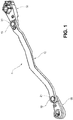
- Figures 1 to 3 show an example of a set of components hinged to each other, in particular a kinematic chain to drive movable parts (not shown) within an air conditioning unit.
- the set of the illustrated example indicated collectively at 1, comprises a first component 10 which in the illustrated example consists of a tie rod, at the ends of which are respectively hinged a second component 20 and a third component 30, which in the illustrated example consist of levers configured to be respectively connected to an actuator (not illustrated) and to a movable part (not illustrated) to be controlled by the actuator.
- a first component 10 which in the illustrated example consists of a tie rod, at the ends of which are respectively hinged a second component 20 and a third component 30, which in the illustrated example consist of levers configured to be respectively connected to an actuator (not illustrated) and to a movable part (not illustrated) to be controlled by the actuator.
- the first component 10 has two holes 12 and 13, and each of the second components 20 and 30 has an articulation pin 21 and 31 coupled to the respective hole 12, 13 of the first component 10.
- the set 1 is produced by multi-material injection molding.
- the first component 10 is a monolithic part made of a first plastic material having a given melting point, e.g. polyamide (PA) 6 or 6,6.
- the second components 20, 30 are each a monolithic part made of a second plastic material having a melting point lower than the melting point of the first plastic material and not adhering to the first plastic material, e.g. polyoxymethylene (POM).
- the articulation pins 21, 31 of the second components are molded within the respective holes 12, 13 of the first component 10.
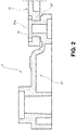
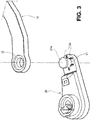
- the hinge connecting the second component indicated at 20 to the first component 10 is shown in Figures 2 and 3 . It is understood that the hinge connecting the second component indicated at 30 to the first component 10 has a similar structure. In this regard, it is noted that the view of Figure 3 has the sole function of showing some details of the hinge otherwise not visible but does not represent in any way an actual condition of the set, since in order to obtain it the articulation pin would have to break.
- ribs 22 arranged around the articulation pin 21 and axially interposed between opposed surfaces of the first and the second component 10, 20. By adjusting the height of the ribs the axial play between the first and the second (third) component may be adjusted.
- FIG. 4 to 9 an example of a mold is represented that allows the set represented in Figures 1-3 to be produced.
- This mold indicated collectively at 40, is configured to process two sets at a time.
- the mold 40 comprises a first half-mold 50 and a second half-mold 60.
- the second half-mold 60 is moved rectilinearly to or from the first half-mold 50 to close and open the mold 40 respectively.
- the second half-mold 60 is rotatable around a central axis z, as shown in Figure 6 .
- Figure 4 shows the mold 40 closed.
- the first plastic material is injected into the first half-mold 50.
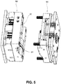
- the mold 40 is then opened ( Figure 5 ), the second half-mold 60 is rotated 180° around the central axis z thereof ( Figure 6 ) and the mold 40 is closed again ( Figure 7 ).
- Figure 5 the part of the second half-mold 60 that in the position of Figure 4 was in contact with the upper part of the first half-mold 50, in the position of Figure 7 is now in contact with the lower part of the first half-mold 50, where the injection of the second plastic material takes place.
- the first half-mold 50 is asymmetrical. As will be explained hereinafter, this allows the molding of the different components in the same mold to be achieved.
- the mold is opened again and the set 10 is ejected ( Figure 8 ) with the actuation of pushing elements 70. These pushing elements are then retracted ( Figure 9 ) to allow the mold to be closed again.
- FIG. 10-16 the molding process carried out with the mold 40 shown in Figures 4 to 9 is illustrated.
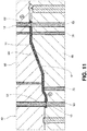
- the cross-section shown in Figures 10 and 11 is taken on a horizontal plane at the top of the mold 40, when the mold is in the closed position shown in Figure 4 .
- the cross-section shown in Figures 12 and 13 is taken on a horizontal plane at the lower part of the mold, after the second half-mold 60 has been rotated and the mold 40 closed in the position shown in Figure 7 .
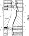
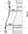
- the cross-section shown in Figures 14 and 16 is taken in the same plane as Figures 12 and 13 , but with the mold open after the second component has been molded ( Figure 14 ), and with the subsequent actuation of the pushing elements 70 ( Figure 16 ).
- the cross-section shown in Figure 15 is taken on a vertical plane, in the direction of the line A-A in Figure 14 .
- first molding seat 61 that cooperates with an opposing surface 51 of the first half-mold 50 to define a first injection cavity C1.
- first and a second hole shaping insert respectively indicated at 52 and 53, having respective ends arranged within the first injection cavity.
- a first and a second movable insert respectively indicated at 62 and 63, which in the position in Figure 10 are positioned with their respective ends abutting against the first and second hole shaping insert, 52 and 53.
- Figure 11 shows the injection of the first molten plastic material M1 into the first injection cavity C1 by means known per se and not represented in the figures.
- the first plastic material M1 fills the first injection cavity C1 and arranges itself around the molding inserts 52 and 53.
- the first component 10 is thus formed with the holes 12 and 13 made with the forming inserts 52 and 53.
- the second half-mold 60 opens and rotates 180°, carrying therewith the first component 10 into the molding seat 61, and then the second half-mold 60 closes on the first half-mold 50 as shown in Figures 5-7 .
- the mold 40 is opened, the forming inserts 52 and 53 integral with the first half-mold 50, have then been extracted from the holes 12 and 13 of the first component 10.
- first component 10 is held in the molding seat 61 of the second half-mold 60 against an opposing surface 51' of the first half-mold 50.
- first and second half-mold 50, 60 cooperate to define two second injection cavities C2, C3, each of which comprises one of the holes 12 and 13 of the first component 10.
- a first and a second pin shaping insert respectively indicated at 52' and 53', which have respective ends arranged respectively between the first hole 12 and the second hole 13 of the first component 10.
- the first and second movable insert are retracted so as to space the end of each movable insert 62 and 63 apart from the respective end of the respective shaping insert 52', 53'. This also creates an axial gap between the end of each insert 62 and 63 and a respective surface surrounding the respective hole 12 and 13 of the first component. Note that the diameter of each movable insert 62, 63 (and thus of the respective cavity into which each movable insert slides) is greater than the diameter of the first hole 12 and the second 13, respectively, in order to create an undercut.
- Figure 13 shows the injection of the second molten plastic material M2 into the second injection cavity C2 and C3, by means known per se and not represented in the figures.
- the second plastic material M2 fills the second injection cavities C2 and C3 and is arranged within the holes 12 and 13 of the first component 10 around the shaping inserts 52' and 53' and in the axial gaps between the movable inserts 62, 63 and the respective surfaces of the first component 10 which surround the holes 12 and 13.
- the second components 20, 30 with the respective articulation pins 21 and 31 are formed.
- Each rotation pin 21, 31 is thus molded within the respective hole 12, 13 which provides for imparting thereto the shape on the radially outer side, while the respective pin shaping insert 52', 53' provides for imparting thereto the shape on the radially inner side.
- the movable inserts 62, 63 with the respective opposing surfaces of the first component 10, on the other hand, provide for creating on each articulation pin 21 and 31 a respective enlarged end 21a, 31a, which defines an undercut with respect to the articulation pin and prevents the articulation pin 21, 32 from slipping out of the respective hole 12, 13.
- movable inserts 54 and 55 which are used to create the ribs (indicated at 22 in Figure 3 ) for adjusting the axial play on the second components 20 and 30.
- Such movable inserts 54 and 55 in the molding configuration of Figures 12 and 13 are positioned around each hole 12 and 13 in contact with the first component 10.
- the movable inserts 54 and 55 are supported by movable arms in a plane orthogonal to that of Figures 12 and 13 .
- Figure 15 shows the movable blades, indicated at 55a, which support the movable inserts 55 associated with the hole 13, but the arrangement is similar for the movable inserts 54 associated with the hole 12.
- the hole 13 is associated with a pair of movable inserts 55 arranged on diametrically opposite sides with respect to the hole 13.
- Each movable insert 55 is supported by a movable blade 55a slidable in an inclined direction.
- the movable inserts 55 are operatively connected with a movable sleeve 55b arranged coaxially with the pin shaping insert 53'.
- Figure 14 also shows the movable sleeve 54b associated with the other shaping insert 52'.
- the sleeves 55b and 54b are further activated and advance towards the second half-mold 60 to free the undercut from the second half-mold 60.
- the movable inserts 54 and 55 move transversely outwards to release the hinges between the first component 10 and the second components 20 and 30.
- the movement of the first half-mold 50 and the movable plates 55a is coordinated in such a way that, in the reference system of the second half-mold 60, the motion of the movable inserts 55 and 54 is purely horizontal.
- Figure 16 shows the open mold, with the actuation of the pushing elements 70 of the second half-mold 60 to cause the complete set 10 to be ejected from the mold.
- the second half-mold 60 is rotated to bring up the empty molding cavity 61, ready for a new injection of the first plastic material, while the first component 10 that has been produced in the upper part of the mold is brought down for the subsequent injection of the second plastic material.
Landscapes
- Engineering & Computer Science (AREA)
- Manufacturing & Machinery (AREA)
- Mechanical Engineering (AREA)
- Moulds For Moulding Plastics Or The Like (AREA)
- Injection Moulding Of Plastics Or The Like (AREA)
Abstract
Description
- The present invention refers in general to the production of kinematic chains made of plastic components hinged to each other.
- In general, the production of such kinematic chains provides for the molding of individual components and their subsequent assembly. In the design of the production process it is therefore necessary to organize the management of the different steps of molding and assembly, as well as the handling of a certain number of different parts. Another issue to take into account is the play that inevitably occurs between the various components.
- One object of the present invention is therefore to make available a product and a method for the production of such a product which allow at least the aforementioned problems to be resolved.
- For this object, the subject-matter of the invention is a set of components hinged to each other, said set comprising at least one first component having at least one hole and at least one second component having an articulation pin coupled to the hole of the first component, wherein said set is produced by multi-material injection molding, wherein said at least one first component is made of a first plastic material having a given melting point, wherein said at least one second component is made of a second plastic material having a lower melting point than the first plastic material and being non-adhesive to the first plastic material, and wherein the articulation pin of the second component is molded within the hole of the first component.
- A further subject-matter of the invention is a method for producing a set of components hinged to each other by multi-material injection molding, said method comprising
- configuring a mold in a first molding configuration, in which within the mold is defined a first injection cavity, comprising at least one area occupied by a mold insert,
- injecting into the mold in the first molding configuration a first plastic material having a given melting point, said first plastic material filling the first injection cavity to form a first component and arranging itself around said at least one area occupied by a shaping insert to form at least one respective hole passing through the first component,
- configuring the mold into a second molding configuration, in which within the mold there is defined at least one second injection cavity, said at least one second cavity comprising said at least one through hole without the hole shaping insert,
- injecting in the mold in the second molding configuration a second plastic material having a lower melting point than the melting point of the first material and being non-adhesive to the first plastic material, said second plastic material filling said at least one second injection cavity to form at least one second component and arranging itself within said at least one hole to form a respective articulation pin of the second component.
- By exploiting, within the molding process, the chemical incompatibility (non-adhesion) of plastic materials and their shrinkage by cooling, it is possible to achieve a coupling between the components with zero play. Furthermore, since the assembled set is already produced within the same mold, it is not necessary to provide for the handling of several different parts, nor to provide for a subsequent assembly step.
- Further features and advantages of the product and of the production method according to the invention will become more apparent in the following detailed description of an embodiment of the invention, made with reference to the accompanying drawings, provided purely to be illustrative and non-restrictive, wherein
-
Figure 1 is a perspective view of a set of hinged components according to the invention; -
Figure 2 is a view in cross-section taken at a hinge between two components of the set ofFigure 1 ; -
Figure 3 is an exploded view taken at the hinge inFigure 2 ; -
Figures 4 to 9 are perspective views of a mold arranged to produce the set ofFigure 1 , in different operating steps; and -
Figures 10 to 16 are views in cross-section taken from various areas of the mold in the different operating steps. -
Figures 1 to 3 show an example of a set of components hinged to each other, in particular a kinematic chain to drive movable parts (not shown) within an air conditioning unit. The set of the illustrated example, indicated collectively at 1, comprises afirst component 10 which in the illustrated example consists of a tie rod, at the ends of which are respectively hinged asecond component 20 and athird component 30, which in the illustrated example consist of levers configured to be respectively connected to an actuator (not illustrated) and to a movable part (not illustrated) to be controlled by the actuator. As may be appreciated, neither the number nor the geometric configuration of the components nor the intended use of the set are essential to the purposes of the invention. - The
first component 10 has twoholes second components articulation pin respective hole first component 10. - The
set 1 is produced by multi-material injection molding. Thefirst component 10 is a monolithic part made of a first plastic material having a given melting point, e.g. polyamide (PA) 6 or 6,6. Thesecond components articulation pins respective holes first component 10. The hinge connecting the second component indicated at 20 to thefirst component 10 is shown inFigures 2 and3 . It is understood that the hinge connecting the second component indicated at 30 to thefirst component 10 has a similar structure. In this regard, it is noted that the view ofFigure 3 has the sole function of showing some details of the hinge otherwise not visible but does not represent in any way an actual condition of the set, since in order to obtain it the articulation pin would have to break. - By playing on the chemical incompatibility of the plastic materials used and their shrinkage during cooling, it is possible to ensure that the radial play between each
hole respective rotation pin - On the second component 20 (and also on the third component) there are formed
ribs 22 arranged around thearticulation pin 21 and axially interposed between opposed surfaces of the first and thesecond component - With reference to
Figures 4 to 9 , an example of a mold is represented that allows the set represented inFigures 1-3 to be produced. This mold, indicated collectively at 40, is configured to process two sets at a time. Themold 40 comprises a first half-mold 50 and a second half-mold 60. In the example illustrated, the second half-mold 60 is moved rectilinearly to or from the first half-mold 50 to close and open themold 40 respectively. Moreover, the second half-mold 60 is rotatable around a central axis z, as shown inFigure 6 . - On diametrically opposite positions of the second half-
mold 60, twoseats 61 are obtained, which are used for the molding and handling of thefirst component 10. -
Figure 4 shows themold 40 closed. The first plastic material is injected into the first half-mold 50. Themold 40 is then opened (Figure 5 ), the second half-mold 60 is rotated 180° around the central axis z thereof (Figure 6 ) and themold 40 is closed again (Figure 7 ). In this way, the part of the second half-mold 60 that in the position ofFigure 4 was in contact with the upper part of the first half-mold 50, in the position ofFigure 7 is now in contact with the lower part of the first half-mold 50, where the injection of the second plastic material takes place. Whereas the second half-mold 60 is rotationally symmetrical with respect to the central axis z, the first half-mold 50 is asymmetrical. As will be explained hereinafter, this allows the molding of the different components in the same mold to be achieved. - Once the molding of the set is finished, the mold is opened again and the
set 10 is ejected (Figure 8 ) with the actuation of pushingelements 70. These pushing elements are then retracted (Figure 9 ) to allow the mold to be closed again. - With reference to
Figures 10-16 , the molding process carried out with themold 40 shown inFigures 4 to 9 is illustrated. The cross-section shown inFigures 10 and11 is taken on a horizontal plane at the top of themold 40, when the mold is in the closed position shown inFigure 4 . The cross-section shown inFigures 12 and13 is taken on a horizontal plane at the lower part of the mold, after the second half-mold 60 has been rotated and themold 40 closed in the position shown inFigure 7 . The cross-section shown inFigures 14 and16 is taken in the same plane asFigures 12 and13 , but with the mold open after the second component has been molded (Figure 14 ), and with the subsequent actuation of the pushing elements 70 (Figure 16 ). The cross-section shown inFigure 15 is taken on a vertical plane, in the direction of the line A-A inFigure 14 . - As may be seen in
Figure 10 , in the second half-mold 60 there is obtained afirst molding seat 61 that cooperates with anopposing surface 51 of the first half-mold 50 to define a first injection cavity C1. On the first half-mold 50 there are arranged a first and a second hole shaping insert, respectively indicated at 52 and 53, having respective ends arranged within the first injection cavity. On the second half-mold 60 there are arranged a first and a second movable insert, respectively indicated at 62 and 63, which in the position inFigure 10 are positioned with their respective ends abutting against the first and second hole shaping insert, 52 and 53. -
Figure 11 shows the injection of the first molten plastic material M1 into the first injection cavity C1 by means known per se and not represented in the figures. The first plastic material M1 fills the first injection cavity C1 and arranges itself around themolding inserts first component 10 is thus formed with theholes inserts mold 60 opens and rotates 180°, carrying therewith thefirst component 10 into themolding seat 61, and then the second half-mold 60 closes on the first half-mold 50 as shown inFigures 5-7 . When themold 40 is opened, the forminginserts mold 50, have then been extracted from theholes first component 10. - When the mold closes as shown in
Figure 7 , themolding seat 61 with thefirst component 10 is then brought against a lower area of the first half-mold 50, different from the upper area shown inFigures 12 and13 , as may be seen inFigure 12 . - In the position shown in
Figure 12 thefirst component 10 is held in themolding seat 61 of the second half-mold 60 against an opposing surface 51' of the first half-mold 50. As may also be seen inFigure 12 , the first and second half-mold holes first component 10. On the first half-mold 50 there are arranged a first and a second pin shaping insert, respectively indicated at 52' and 53', which have respective ends arranged respectively between thefirst hole 12 and thesecond hole 13 of thefirst component 10. On the second half-mold 60, the first and second movable insert, indicated at 62 and 63 respectively, are retracted so as to space the end of eachmovable insert insert respective hole movable insert 62, 63 (and thus of the respective cavity into which each movable insert slides) is greater than the diameter of thefirst hole 12 and the second 13, respectively, in order to create an undercut. -
Figure 13 shows the injection of the second molten plastic material M2 into the second injection cavity C2 and C3, by means known per se and not represented in the figures. The second plastic material M2 fills the second injection cavities C2 and C3 and is arranged within theholes first component 10 around the shaping inserts 52' and 53' and in the axial gaps between themovable inserts first component 10 which surround theholes second components rotation pin respective hole movable inserts first component 10, on the other hand, provide for creating on eacharticulation pin enlarged end articulation pin 21, 32 from slipping out of therespective hole - As may also be seen in
Figures 12 and13 , on the first half-mold 50 there are also arrangedmovable inserts Figure 3 ) for adjusting the axial play on thesecond components - Such
movable inserts Figures 12 and13 are positioned around eachhole first component 10. Themovable inserts Figures 12 and13 .Figure 15 shows the movable blades, indicated at 55a, which support themovable inserts 55 associated with thehole 13, but the arrangement is similar for themovable inserts 54 associated with thehole 12. As may be seen, thehole 13 is associated with a pair ofmovable inserts 55 arranged on diametrically opposite sides with respect to thehole 13. Eachmovable insert 55 is supported by amovable blade 55a slidable in an inclined direction. Themovable inserts 55 are operatively connected with amovable sleeve 55b arranged coaxially with the pin shaping insert 53'.Figure 14 also shows themovable sleeve 54b associated with the other shaping insert 52'. - When the second half-
mold 60 is moved away from the first half-mold 50 to open the mold 40 (Figure 14 ), thesleeves mold 60 to free the undercut from the second half-mold 60. At the same time, as shown inFigure 15 , themovable inserts first component 10 and thesecond components mold 50 and themovable plates 55a is coordinated in such a way that, in the reference system of the second half-mold 60, the motion of themovable inserts -
Figure 16 shows the open mold, with the actuation of the pushingelements 70 of the second half-mold 60 to cause the complete set 10 to be ejected from the mold. - Although in the description of the process reference has been made for simplicity to the production of only one
set 10, it is actually possible to process two sets at a time in the mold. In particular, when, in the upper part of themold 40, the first plastic material is injected into the first injection cavity C1, in the lower part of themold 40, the second plastic material is injected into the second injection cavities C2 and C3 on thefirst component 10, which was produced in the upper part ofmold 40 in the previous step of the operating cycle. Once thecomplete set 10 is ejected from the lower part of themold 40, the second half-mold 60 is rotated to bring up theempty molding cavity 61, ready for a new injection of the first plastic material, while thefirst component 10 that has been produced in the upper part of the mold is brought down for the subsequent injection of the second plastic material. - It is understood that the invention is not limited to the embodiments described and illustrated herein, but rather may undergo modifications relating to the shape and arrangement of parts, construction and operating details according to the numerous possible variants which will appear suitable to persons skilled in the art and which are to be understood as comprised in the scope of the invention, as defined by the following claims.
Claims (4)
- A set of components (10, 20, 30) hinged to each other, said set comprising at least one first component (10) having at least one hole (12, 13) and at least one second component (20, 30) having an articulation pin (21, 31) coupled to the hole (12, 13) of the first component (10), wherein said set is produced by multi-material injection molding, wherein said at least one first component (10) is made of a first plastic material having a given melting point, wherein said at least one second component (20, 30) is made of a second plastic material having a lower melting point than the first plastic material and being non-adhesive to the first plastic material, and wherein the articulation pin (21, 31) of the second component (20, 30) is molded within the hole (12, 13) of the first component (10).
- A set according to claim 1, wherein on the second component (20, 30) there are formed ribs (22) arranged around the articulation pin (21, 31) and axially interposed between opposed surfaces of the first (10) and second component (20, 30).
- A method for producing a set of components (10, 20, 30) hinged to each other by multi-material injection molding, said method comprising
configuring a mold (40) into a first molding configuration, in which within the mold (40) there is defined a first injection cavity (C1) within which at least one hole shaping insert (52, 53) extends,
injecting into the mold (40) in the first molding configuration a first plastic material having a given melting point, said first plastic material filling the first injection cavity (C1) to form a first component (10) and arranging itself around said hole shaping insert to form at least one respective hole (12, 13) through the first component (10),
configuring the mold (40) into a second molding configuration, in which within the mold (40) there is defined at least one second injection cavity (C2, C3), said at least one second injection cavity comprising said at least one through hole (12, 13) without the hole shaping insert (52, 53),
injecting into the mold (40) in the second molding configuration a second plastic material having a lower melting point than the first material and being non-adhesive to the first plastic material, said second plastic material filling said at least one second injection cavity (C2, C3) to form at least one second component (20, 30) and arranging itself within said at least one hole (12, 13) to form a respective articulation pin (21, 31) of the second component (20, 30). - A method according to claim 3, wherein in the second molding configuration transversely movable inserts (55, 56) are positioned around said at least one hole (12, 13) in contact with the first component (10) to form on the second component (20, 30) ribs (22) arranged around the articulation pin (21, 31) and axially interposed between opposed surfaces of the first (10) and second component (20, 30).
Applications Claiming Priority (1)
| Application Number | Priority Date | Filing Date | Title |
|---|---|---|---|
| IT102019000001489A IT201900001489A1 (en) | 2019-02-01 | 2019-02-01 | Group of hinged components produced by multi-material injection molding |
Publications (2)
| Publication Number | Publication Date |
|---|---|
| EP3689573A1 true EP3689573A1 (en) | 2020-08-05 |
| EP3689573B1 EP3689573B1 (en) | 2022-08-10 |
Family
ID=66286789
Family Applications (1)
| Application Number | Title | Priority Date | Filing Date |
|---|---|---|---|
| EP20154754.4A Active EP3689573B1 (en) | 2019-02-01 | 2020-01-31 | A set of hinged components produced by multi-material injection molding |
Country Status (5)
| Country | Link |
|---|---|
| EP (1) | EP3689573B1 (en) |
| ES (1) | ES2929843T3 (en) |
| IT (1) | IT201900001489A1 (en) |
| PL (1) | PL3689573T3 (en) |
| PT (1) | PT3689573T (en) |
Cited By (1)
| Publication number | Priority date | Publication date | Assignee | Title |
|---|---|---|---|---|
| CN113351861A (en) * | 2021-06-07 | 2021-09-07 | 三进光电(苏州)有限公司 | Method for preparing hinge by mixing and molding metal powder and high polymer material |
Citations (6)
| Publication number | Priority date | Publication date | Assignee | Title |
|---|---|---|---|---|
| GB2117694A (en) * | 1980-10-22 | 1983-10-19 | Nihon Plast Co Ltd | Method of moulding ventilator grills |
| JPS58219031A (en) * | 1982-06-15 | 1983-12-20 | Sony Corp | Manufacture of structural component |
| DE19808223A1 (en) * | 1998-02-27 | 1999-09-02 | Behr Gmbh & Co | Lever mechanism for operation of vehicle air conditioning and heating flaps |
| US6261499B1 (en) * | 1993-07-19 | 2001-07-17 | Xerox Corporation | Molded inseparable assembly |
| EP2492127A1 (en) * | 2011-02-22 | 2012-08-29 | Valeo Systèmes Thermiques | Frame for cooling module of a vehicle engine |
| WO2015086601A1 (en) * | 2013-12-09 | 2015-06-18 | Valeo Systemes Thermiques | Heating, ventilation and/or air-conditioning system for motor vehicles |
-
2019
- 2019-02-01 IT IT102019000001489A patent/IT201900001489A1/en unknown
-
2020
- 2020-01-31 EP EP20154754.4A patent/EP3689573B1/en active Active
- 2020-01-31 PL PL20154754.4T patent/PL3689573T3/en unknown
- 2020-01-31 PT PT201547544T patent/PT3689573T/en unknown
- 2020-01-31 ES ES20154754T patent/ES2929843T3/en active Active
Patent Citations (6)
| Publication number | Priority date | Publication date | Assignee | Title |
|---|---|---|---|---|
| GB2117694A (en) * | 1980-10-22 | 1983-10-19 | Nihon Plast Co Ltd | Method of moulding ventilator grills |
| JPS58219031A (en) * | 1982-06-15 | 1983-12-20 | Sony Corp | Manufacture of structural component |
| US6261499B1 (en) * | 1993-07-19 | 2001-07-17 | Xerox Corporation | Molded inseparable assembly |
| DE19808223A1 (en) * | 1998-02-27 | 1999-09-02 | Behr Gmbh & Co | Lever mechanism for operation of vehicle air conditioning and heating flaps |
| EP2492127A1 (en) * | 2011-02-22 | 2012-08-29 | Valeo Systèmes Thermiques | Frame for cooling module of a vehicle engine |
| WO2015086601A1 (en) * | 2013-12-09 | 2015-06-18 | Valeo Systemes Thermiques | Heating, ventilation and/or air-conditioning system for motor vehicles |
Cited By (1)
| Publication number | Priority date | Publication date | Assignee | Title |
|---|---|---|---|---|
| CN113351861A (en) * | 2021-06-07 | 2021-09-07 | 三进光电(苏州)有限公司 | Method for preparing hinge by mixing and molding metal powder and high polymer material |
Also Published As
| Publication number | Publication date |
|---|---|
| PT3689573T (en) | 2022-11-08 |
| PL3689573T3 (en) | 2023-01-16 |
| EP3689573B1 (en) | 2022-08-10 |
| ES2929843T3 (en) | 2022-12-02 |
| IT201900001489A1 (en) | 2020-08-01 |
Similar Documents
| Publication | Publication Date | Title |
|---|---|---|
| US7452202B2 (en) | Machinery for the molding and assembling of an assembled object | |
| US4414170A (en) | Method of producing ventilator grills | |
| CN100398296C (en) | Metal mold for combined product and forming method thereof | |
| EP3689573B1 (en) | A set of hinged components produced by multi-material injection molding | |
| CN107127936A (en) | Including the separator for mould for the chain being made up of articulated links | |
| JP2019001109A (en) | Method for manufacturing two-color molded article and two-color molding mold | |
| WO2025192392A1 (en) | Model element and method for producing same | |
| CN120457013A (en) | Method and forming die for manufacturing plastic roller | |
| JPH03193332A (en) | Monolithic molding method for optical system such as lens and frame, mold and monolithic molded product | |
| TW202134030A (en) | Method and mould for making holed objects from plastic material | |
| WO2015051271A1 (en) | Double die rotate molding | |
| JP2981422B2 (en) | Molding apparatus, molding method and molded article | |
| US20130334733A1 (en) | Press for manufacturing a one-piece object and method for using said press | |
| JP3870100B2 (en) | Mold apparatus for die casting and method for molding die cast product having undercut | |
| KR100849533B1 (en) | Multi Injection Mold | |
| JP4789645B2 (en) | Manufacturing method and manufacturing apparatus for resin molded product | |
| CN117836112A (en) | Injection molding device with rotatable core member | |
| KR101568701B1 (en) | R2k injection mold and method thereof | |
| JPH09290442A (en) | Molding equipment | |
| JP7743143B2 (en) | injection molding equipment | |
| JP3572013B2 (en) | Composite molding method and injection molding machine | |
| JPH08300406A (en) | Mold device for composite molding and two-color molding method | |
| JP3643820B2 (en) | Dissimilar / different color integrated injection molding method and apparatus | |
| JP2000317981A (en) | Molding tool for producing a plurality of constituent parts by assemble injection molding | |
| JP3047212B2 (en) | Molding method and molding die for laminated molded article |
Legal Events
| Date | Code | Title | Description |
|---|---|---|---|
| PUAI | Public reference made under article 153(3) epc to a published international application that has entered the european phase |
Free format text: ORIGINAL CODE: 0009012 |
|
| STAA | Information on the status of an ep patent application or granted ep patent |
Free format text: STATUS: THE APPLICATION HAS BEEN PUBLISHED |
|
| AK | Designated contracting states |
Kind code of ref document: A1 Designated state(s): AL AT BE BG CH CY CZ DE DK EE ES FI FR GB GR HR HU IE IS IT LI LT LU LV MC MK MT NL NO PL PT RO RS SE SI SK SM TR |
|
| AX | Request for extension of the european patent |
Extension state: BA ME |
|
| STAA | Information on the status of an ep patent application or granted ep patent |
Free format text: STATUS: REQUEST FOR EXAMINATION WAS MADE |
|
| 17P | Request for examination filed |
Effective date: 20210202 |
|
| RBV | Designated contracting states (corrected) |
Designated state(s): AL AT BE BG CH CY CZ DE DK EE ES FI FR GB GR HR HU IE IS IT LI LT LU LV MC MK MT NL NO PL PT RO RS SE SI SK SM TR |
|
| GRAP | Despatch of communication of intention to grant a patent |
Free format text: ORIGINAL CODE: EPIDOSNIGR1 |
|
| STAA | Information on the status of an ep patent application or granted ep patent |
Free format text: STATUS: GRANT OF PATENT IS INTENDED |
|
| RIC1 | Information provided on ipc code assigned before grant |
Ipc: B60H 1/00 20060101ALN20220228BHEP Ipc: B29C 45/44 20060101ALN20220228BHEP Ipc: B29C 45/33 20060101ALN20220228BHEP Ipc: B29C 45/26 20060101ALI20220228BHEP Ipc: B29C 45/16 20060101ALI20220228BHEP Ipc: B29C 45/00 20060101AFI20220228BHEP |
|
| RIC1 | Information provided on ipc code assigned before grant |
Ipc: B60H 1/00 20060101ALN20220307BHEP Ipc: B29C 45/44 20060101ALN20220307BHEP Ipc: B29C 45/33 20060101ALN20220307BHEP Ipc: B29C 45/26 20060101ALI20220307BHEP Ipc: B29C 45/16 20060101ALI20220307BHEP Ipc: B29C 45/00 20060101AFI20220307BHEP |
|
| INTG | Intention to grant announced |
Effective date: 20220323 |
|
| GRAS | Grant fee paid |
Free format text: ORIGINAL CODE: EPIDOSNIGR3 |
|
| GRAA | (expected) grant |
Free format text: ORIGINAL CODE: 0009210 |
|
| STAA | Information on the status of an ep patent application or granted ep patent |
Free format text: STATUS: THE PATENT HAS BEEN GRANTED |
|
| AK | Designated contracting states |
Kind code of ref document: B1 Designated state(s): AL AT BE BG CH CY CZ DE DK EE ES FI FR GB GR HR HU IE IS IT LI LT LU LV MC MK MT NL NO PL PT RO RS SE SI SK SM TR |
|
| REG | Reference to a national code |
Ref country code: AT Ref legal event code: REF Ref document number: 1510173 Country of ref document: AT Kind code of ref document: T Effective date: 20220815 Ref country code: CH Ref legal event code: EP |
|
| REG | Reference to a national code |
Ref country code: IE Ref legal event code: FG4D |
|
| REG | Reference to a national code |
Ref country code: DE Ref legal event code: R096 Ref document number: 602020004382 Country of ref document: DE |
|
| REG | Reference to a national code |
Ref country code: PT Ref legal event code: SC4A Ref document number: 3689573 Country of ref document: PT Date of ref document: 20221108 Kind code of ref document: T Free format text: AVAILABILITY OF NATIONAL TRANSLATION Effective date: 20221102 |
|
| REG | Reference to a national code |
Ref country code: ES Ref legal event code: FG2A Ref document number: 2929843 Country of ref document: ES Kind code of ref document: T3 Effective date: 20221202 |
|
| REG | Reference to a national code |
Ref country code: SK Ref legal event code: T3 Ref document number: E 40637 Country of ref document: SK |
|
| REG | Reference to a national code |
Ref country code: NL Ref legal event code: MP Effective date: 20220810 |
|
| REG | Reference to a national code |
Ref country code: LT Ref legal event code: MG9D |
|
| PG25 | Lapsed in a contracting state [announced via postgrant information from national office to epo] |
Ref country code: SE Free format text: LAPSE BECAUSE OF FAILURE TO SUBMIT A TRANSLATION OF THE DESCRIPTION OR TO PAY THE FEE WITHIN THE PRESCRIBED TIME-LIMIT Effective date: 20220810 Ref country code: RS Free format text: LAPSE BECAUSE OF FAILURE TO SUBMIT A TRANSLATION OF THE DESCRIPTION OR TO PAY THE FEE WITHIN THE PRESCRIBED TIME-LIMIT Effective date: 20220810 Ref country code: NO Free format text: LAPSE BECAUSE OF FAILURE TO SUBMIT A TRANSLATION OF THE DESCRIPTION OR TO PAY THE FEE WITHIN THE PRESCRIBED TIME-LIMIT Effective date: 20221110 Ref country code: NL Free format text: LAPSE BECAUSE OF FAILURE TO SUBMIT A TRANSLATION OF THE DESCRIPTION OR TO PAY THE FEE WITHIN THE PRESCRIBED TIME-LIMIT Effective date: 20220810 Ref country code: LV Free format text: LAPSE BECAUSE OF FAILURE TO SUBMIT A TRANSLATION OF THE DESCRIPTION OR TO PAY THE FEE WITHIN THE PRESCRIBED TIME-LIMIT Effective date: 20220810 Ref country code: LT Free format text: LAPSE BECAUSE OF FAILURE TO SUBMIT A TRANSLATION OF THE DESCRIPTION OR TO PAY THE FEE WITHIN THE PRESCRIBED TIME-LIMIT Effective date: 20220810 Ref country code: FI Free format text: LAPSE BECAUSE OF FAILURE TO SUBMIT A TRANSLATION OF THE DESCRIPTION OR TO PAY THE FEE WITHIN THE PRESCRIBED TIME-LIMIT Effective date: 20220810 |
|
| REG | Reference to a national code |
Ref country code: AT Ref legal event code: MK05 Ref document number: 1510173 Country of ref document: AT Kind code of ref document: T Effective date: 20220810 |
|
| PG25 | Lapsed in a contracting state [announced via postgrant information from national office to epo] |
Ref country code: IS Free format text: LAPSE BECAUSE OF FAILURE TO SUBMIT A TRANSLATION OF THE DESCRIPTION OR TO PAY THE FEE WITHIN THE PRESCRIBED TIME-LIMIT Effective date: 20221210 Ref country code: HR Free format text: LAPSE BECAUSE OF FAILURE TO SUBMIT A TRANSLATION OF THE DESCRIPTION OR TO PAY THE FEE WITHIN THE PRESCRIBED TIME-LIMIT Effective date: 20220810 Ref country code: GR Free format text: LAPSE BECAUSE OF FAILURE TO SUBMIT A TRANSLATION OF THE DESCRIPTION OR TO PAY THE FEE WITHIN THE PRESCRIBED TIME-LIMIT Effective date: 20221111 |
|
| PG25 | Lapsed in a contracting state [announced via postgrant information from national office to epo] |
Ref country code: SM Free format text: LAPSE BECAUSE OF FAILURE TO SUBMIT A TRANSLATION OF THE DESCRIPTION OR TO PAY THE FEE WITHIN THE PRESCRIBED TIME-LIMIT Effective date: 20220810 Ref country code: RO Free format text: LAPSE BECAUSE OF FAILURE TO SUBMIT A TRANSLATION OF THE DESCRIPTION OR TO PAY THE FEE WITHIN THE PRESCRIBED TIME-LIMIT Effective date: 20220810 Ref country code: DK Free format text: LAPSE BECAUSE OF FAILURE TO SUBMIT A TRANSLATION OF THE DESCRIPTION OR TO PAY THE FEE WITHIN THE PRESCRIBED TIME-LIMIT Effective date: 20220810 Ref country code: AT Free format text: LAPSE BECAUSE OF FAILURE TO SUBMIT A TRANSLATION OF THE DESCRIPTION OR TO PAY THE FEE WITHIN THE PRESCRIBED TIME-LIMIT Effective date: 20220810 |
|
| REG | Reference to a national code |
Ref country code: DE Ref legal event code: R097 Ref document number: 602020004382 Country of ref document: DE |
|
| PG25 | Lapsed in a contracting state [announced via postgrant information from national office to epo] |
Ref country code: EE Free format text: LAPSE BECAUSE OF FAILURE TO SUBMIT A TRANSLATION OF THE DESCRIPTION OR TO PAY THE FEE WITHIN THE PRESCRIBED TIME-LIMIT Effective date: 20220810 |
|
| PLBE | No opposition filed within time limit |
Free format text: ORIGINAL CODE: 0009261 |
|
| STAA | Information on the status of an ep patent application or granted ep patent |
Free format text: STATUS: NO OPPOSITION FILED WITHIN TIME LIMIT |
|
| PG25 | Lapsed in a contracting state [announced via postgrant information from national office to epo] |
Ref country code: AL Free format text: LAPSE BECAUSE OF FAILURE TO SUBMIT A TRANSLATION OF THE DESCRIPTION OR TO PAY THE FEE WITHIN THE PRESCRIBED TIME-LIMIT Effective date: 20220810 |
|
| 26N | No opposition filed |
Effective date: 20230511 |
|
| PG25 | Lapsed in a contracting state [announced via postgrant information from national office to epo] |
Ref country code: SI Free format text: LAPSE BECAUSE OF FAILURE TO SUBMIT A TRANSLATION OF THE DESCRIPTION OR TO PAY THE FEE WITHIN THE PRESCRIBED TIME-LIMIT Effective date: 20220810 |
|
| REG | Reference to a national code |
Ref country code: CH Ref legal event code: PL |
|
| PG25 | Lapsed in a contracting state [announced via postgrant information from national office to epo] |
Ref country code: LU Free format text: LAPSE BECAUSE OF NON-PAYMENT OF DUE FEES Effective date: 20230131 |
|
| REG | Reference to a national code |
Ref country code: BE Ref legal event code: MM Effective date: 20230131 |
|
| PG25 | Lapsed in a contracting state [announced via postgrant information from national office to epo] |
Ref country code: LI Free format text: LAPSE BECAUSE OF NON-PAYMENT OF DUE FEES Effective date: 20230131 Ref country code: CH Free format text: LAPSE BECAUSE OF NON-PAYMENT OF DUE FEES Effective date: 20230131 |
|
| PG25 | Lapsed in a contracting state [announced via postgrant information from national office to epo] |
Ref country code: BE Free format text: LAPSE BECAUSE OF NON-PAYMENT OF DUE FEES Effective date: 20230131 |
|
| PG25 | Lapsed in a contracting state [announced via postgrant information from national office to epo] |
Ref country code: IE Free format text: LAPSE BECAUSE OF NON-PAYMENT OF DUE FEES Effective date: 20230131 |
|
| PG25 | Lapsed in a contracting state [announced via postgrant information from national office to epo] |
Ref country code: IT Free format text: LAPSE BECAUSE OF FAILURE TO SUBMIT A TRANSLATION OF THE DESCRIPTION OR TO PAY THE FEE WITHIN THE PRESCRIBED TIME-LIMIT Effective date: 20220810 |
|
| PG25 | Lapsed in a contracting state [announced via postgrant information from national office to epo] |
Ref country code: MC Free format text: LAPSE BECAUSE OF FAILURE TO SUBMIT A TRANSLATION OF THE DESCRIPTION OR TO PAY THE FEE WITHIN THE PRESCRIBED TIME-LIMIT Effective date: 20220810 |
|
| PG25 | Lapsed in a contracting state [announced via postgrant information from national office to epo] |
Ref country code: MC Free format text: LAPSE BECAUSE OF FAILURE TO SUBMIT A TRANSLATION OF THE DESCRIPTION OR TO PAY THE FEE WITHIN THE PRESCRIBED TIME-LIMIT Effective date: 20220810 |
|
| GBPC | Gb: european patent ceased through non-payment of renewal fee |
Effective date: 20240131 |
|
| PG25 | Lapsed in a contracting state [announced via postgrant information from national office to epo] |
Ref country code: GB Free format text: LAPSE BECAUSE OF NON-PAYMENT OF DUE FEES Effective date: 20240131 |
|
| PG25 | Lapsed in a contracting state [announced via postgrant information from national office to epo] |
Ref country code: GB Free format text: LAPSE BECAUSE OF NON-PAYMENT OF DUE FEES Effective date: 20240131 |
|
| PG25 | Lapsed in a contracting state [announced via postgrant information from national office to epo] |
Ref country code: BG Free format text: LAPSE BECAUSE OF FAILURE TO SUBMIT A TRANSLATION OF THE DESCRIPTION OR TO PAY THE FEE WITHIN THE PRESCRIBED TIME-LIMIT Effective date: 20220810 |
|
| PG25 | Lapsed in a contracting state [announced via postgrant information from national office to epo] |
Ref country code: BG Free format text: LAPSE BECAUSE OF FAILURE TO SUBMIT A TRANSLATION OF THE DESCRIPTION OR TO PAY THE FEE WITHIN THE PRESCRIBED TIME-LIMIT Effective date: 20220810 |
|
| PG25 | Lapsed in a contracting state [announced via postgrant information from national office to epo] |
Ref country code: CY Free format text: LAPSE BECAUSE OF FAILURE TO SUBMIT A TRANSLATION OF THE DESCRIPTION OR TO PAY THE FEE WITHIN THE PRESCRIBED TIME-LIMIT; INVALID AB INITIO Effective date: 20200131 |
|
| PG25 | Lapsed in a contracting state [announced via postgrant information from national office to epo] |
Ref country code: HU Free format text: LAPSE BECAUSE OF FAILURE TO SUBMIT A TRANSLATION OF THE DESCRIPTION OR TO PAY THE FEE WITHIN THE PRESCRIBED TIME-LIMIT; INVALID AB INITIO Effective date: 20200131 |
|
| PG25 | Lapsed in a contracting state [announced via postgrant information from national office to epo] |
Ref country code: TR Free format text: LAPSE BECAUSE OF FAILURE TO SUBMIT A TRANSLATION OF THE DESCRIPTION OR TO PAY THE FEE WITHIN THE PRESCRIBED TIME-LIMIT Effective date: 20220810 |
|
| PGFP | Annual fee paid to national office [announced via postgrant information from national office to epo] |
Ref country code: FR Payment date: 20251231 Year of fee payment: 7 |
|
| PGFP | Annual fee paid to national office [announced via postgrant information from national office to epo] |
Ref country code: CZ Payment date: 20251223 Year of fee payment: 7 |
|
| PGFP | Annual fee paid to national office [announced via postgrant information from national office to epo] |
Ref country code: ES Payment date: 20260202 Year of fee payment: 7 |
|
| PGFP | Annual fee paid to national office [announced via postgrant information from national office to epo] |
Ref country code: DE Payment date: 20260123 Year of fee payment: 7 |
|
| PGFP | Annual fee paid to national office [announced via postgrant information from national office to epo] |
Ref country code: PT Payment date: 20260122 Year of fee payment: 7 |
|
| PGFP | Annual fee paid to national office [announced via postgrant information from national office to epo] |
Ref country code: PL Payment date: 20260114 Year of fee payment: 7 |
|
| PGFP | Annual fee paid to national office [announced via postgrant information from national office to epo] |
Ref country code: SK Payment date: 20260126 Year of fee payment: 7 |