EP3689547A1 - Power tool - Google Patents
Power tool Download PDFInfo
- Publication number
- EP3689547A1 EP3689547A1 EP18861058.8A EP18861058A EP3689547A1 EP 3689547 A1 EP3689547 A1 EP 3689547A1 EP 18861058 A EP18861058 A EP 18861058A EP 3689547 A1 EP3689547 A1 EP 3689547A1
- Authority
- EP
- European Patent Office
- Prior art keywords
- surface portion
- anvil
- recessed
- curved surface
- flat surface
- Prior art date
- Legal status (The legal status is an assumption and is not a legal conclusion. Google has not performed a legal analysis and makes no representation as to the accuracy of the status listed.)
- Granted
Links
Images







Classifications
-
- B—PERFORMING OPERATIONS; TRANSPORTING
- B25—HAND TOOLS; PORTABLE POWER-DRIVEN TOOLS; MANIPULATORS
- B25B—TOOLS OR BENCH DEVICES NOT OTHERWISE PROVIDED FOR, FOR FASTENING, CONNECTING, DISENGAGING, OR HOLDING
- B25B21/00—Portable power-driven screw or nut setting or loosening tools; Attachments for drilling apparatus serving the same purpose
- B25B21/02—Portable power-driven screw or nut setting or loosening tools; Attachments for drilling apparatus serving the same purpose with means for imparting impact to screwdriver blade or nut socket
-
- B—PERFORMING OPERATIONS; TRANSPORTING
- B25—HAND TOOLS; PORTABLE POWER-DRIVEN TOOLS; MANIPULATORS
- B25B—TOOLS OR BENCH DEVICES NOT OTHERWISE PROVIDED FOR, FOR FASTENING, CONNECTING, DISENGAGING, OR HOLDING
- B25B21/00—Portable power-driven screw or nut setting or loosening tools; Attachments for drilling apparatus serving the same purpose
- B25B21/02—Portable power-driven screw or nut setting or loosening tools; Attachments for drilling apparatus serving the same purpose with means for imparting impact to screwdriver blade or nut socket
- B25B21/026—Impact clutches
-
- B—PERFORMING OPERATIONS; TRANSPORTING
- B25—HAND TOOLS; PORTABLE POWER-DRIVEN TOOLS; MANIPULATORS
- B25B—TOOLS OR BENCH DEVICES NOT OTHERWISE PROVIDED FOR, FOR FASTENING, CONNECTING, DISENGAGING, OR HOLDING
- B25B23/00—Details of, or accessories for, spanners, wrenches, screwdrivers
- B25B23/0007—Connections or joints between tool parts
- B25B23/0035—Connection means between socket or screwdriver bit and tool
Definitions
- the present invention relates to a power tool provided with an impact mechanism.
- an impact tool such as an impact driver and an impact wrench
- an electric power tool where rotation of a motor is converted to a rotational impacting force through an impact mechanism and the force is transmitted to an end bit.
- Patent Literature PTL1 discloses an impact tool provided with an impact mechanism including a hammer rotatable by the rotational driving force from a motor, and an anvil having an attachment portion to which an end bit is attached.
- the hammer drivingly rotated by the motor rotationally impacts the anvil.
- Operation for fastening a fastener such as a screw and a bolt is performed by the rotation of the end bit attached to the attachment portion.
- the present invention provides a power tool.
- the electric power tool includes a housing, a motor, an anvil and an impact mechanism.
- the motor is accommodated in the housing and rotatable.
- the anvil is supported by the housing and rotatable about an axis.
- the impact mechanism is configured to convert a rotational force generated by the motor into a rotational impact force about the axis, and to apply the rotational impact force to the anvil.
- the anvil includes a base portion, an end bit attachment portion, and a connecting portion.
- the base portion is rotatably supported by the housing.
- An end bit is attachable to the end bit attachment portion.
- the end bit attachment portion has a flat surface portion.
- the connecting portion integrally connects together the base portion and the end bit attachment portion.
- the connecting portion has a diameter gradually reduced, in a direction from the base portion toward the end bit attachment portion.
- the connecting portion is formed with a recessed portion.
- the connecting portion has an outer peripheral surface portion where the recessed portion is formed.
- the recessed portion is recessed, in an axial direction from the end bit attachment portion toward the base portion, from a point where the recessed portion is connected to the outer peripheral surface portion in a cross-section taken along a plane parallel to the flat surface portion and passing through the recessed portion.
- the recessed portion is in contact with the flat surface portion. Or, preferably, the recessed portion is separated from the flat surface portion.
- the recessed portion includes a first recessed portion in contact with the flat surface portion, and a second recessed portion separated from the flat surface portion.
- the recessed portion has a curved-line shape recessed in the axial direction in the cross-section.
- the connecting portion has an outer peripheral surface portion where the recessed portion is formed.
- the recessed portion is recessed, in an axial direction, from a point where the recessed portion is connected to the outer peripheral surface portion in a cross-section taken along a plane parallel to the flat surface portion and passing through the recessed portion.
- the recessed portion has a curved-line shape recessed in the axial direction in the cross-section.
- the recessed portion has an arcuate shape recessed in the axial direction in the cross-section.
- the recessed portion has a parabolic-curve shape recessed in the axial direction in the cross-section.
- the electric power tool including the anvil capable of restraining stress concentration can be provided.
- the impact wrench 1 is an electrically powered power tool for fastening a fastener (such as a bolt and a screw) to a workpiece (such as steel and wood).
- a fastener such as a bolt and a screw
- a workpiece such as steel and wood
- the impact wrench 1 illustrated in Figs. 1 and 2 is an electrically powered fastening tool. As illustrated in Fig. 2 , the impact wrench 1 includes a motor 2, a gear mechanism 3, an impact mechanism 4, an anvil 5, a controller 6, and a battery pack 73.
- the impact wrench 1 has: an outer shell including a housing 7 accommodating therein the motor 2; a hammer case 8 accommodating therein the gear mechanism 3 and the impact mechanism 4; and a cover 8 covering an outer peripheral surface of the hammer case 8.
- the housing 7 is made from resin, and includes a barrel portion 71 and a handle portion 72.
- the barrel portion 71 is generally hollow cylindrical.
- the barrel portion 71 in cooperation with the hammer case 8, accommodates therein the motor 2, the gear mechanism 3, the impact mechanism 4, and the anvil 5 arrayed in this order in the frontward direction.
- the handle portion 72 extends downward from a front end portion of a lower surface of the barrel portion 71.
- the handle portion 72 is integral with the barrel portion 71.
- the hammer case 8 is made from aluminum, and is positioned frontward of the barrel portion 71, and generally hollow cylindrical.
- the hammer case 8 includes a reduced diameter portion 801.
- the reduced diameter portion 801 is generally hollow cylindrical and extends in the frontward/rearward direction.
- the reduced diameter portion 801 has an inner peripheral surface to which a bearing metal 10 is fixed by force-fitting.
- the reduced diameter portion 801 has a front end portion forming an opening.
- the cover 9 is made from resin, and is positioned to cover a front end portion of an outer peripheral surface of the hammer case 8.
- the cover 9 has a front end portion forming an opening.
- the motor 2 is a brushless motor including a rotation shaft 21, a rotor 22, a stator 23, and a fan 24.
- the rotation shaft 21 extends in the frontward/rearward direction, and is rotatably supported by the barrel portion 71 through a bearing.
- the rotor 22 includes a plurality of permanent magnets not illustrated, and extends in the frontward/rearward direction.
- the rotor 22 is fixed to the rotation shaft 21 to rotate integrally therewith.
- the stator 23 includes a plurality of stator windings not illustrated.
- the stator 23 is fixed to the barrel portion 71 to surround the rotor 22.
- the fan 24 is provided at the rotation shaft 21 and is positioned frontward of a front surface of the rotor 22.
- the fan 24 is fixed to the rotation shaft 21 to rotate integrally therewith.
- the gear mechanism 3 includes a pinion gear 31 positioned at a front end portion of the rotation shaft 21 of the motor 2, a pair of gears 32 in meshing engagement with the pinion gear 31, and an outer gear (not illustrated) in meshing engagement with the gears 32.
- the gear mechanism 3 is a planetary gear mechanism where the pinion gear 31 functions as a sun gear and the pair of gears 32 functions as planetary gears.
- the gear mechanism 3 is configured so that the rotation of the pinion gear 31 is deceleratingly transmitted to the impact mechanism 4.
- the impact mechanism 4 includes a spindle 41, balls 42, a spring 43, and a hammer 46.
- the spindle 41 has an outer peripheral surface formed with two grooves 41a having generally V-shape.
- the balls 42 are positioned at the grooves 41a so as to be movable along the grooves 41a in the frontward/rearward direction.
- the spring 43 is a coil spring disposed over the spindle 41.
- the spring 43 has an annular shape in the front view.
- the spindle 41 has a tip end portion forming a protruding portion 41C.
- the spring 43 has a front end portion in abutment with the hammer 46 for urging the hammer 46 frontward.
- the spring 43 has a rear end portion in abutment with the spindle 41.
- the hammer 46 is positioned in the hammer case 8 and is rotatable about an axis A extending in the frontward/rearward direction.
- the hammer 46 includes a body portion 46A and a pair of pawls 46B (as indicated by dotted line in Fig. 2 ).
- the axis A is coincident with the rotation axis of the rotor 22.
- the body portion 46A has an inner peripheral surface formed with two grooves 46e extending in the frontward/rearward direction and recessed radially outwardly.
- Each groove 46e is positioned in confrontation with each groove 41a of the spindle 41 so as to support the balls 42 in cooperation with the groove 41a.
- the hammer 46 is movable relative to the spindle 41 in the frontward/rearward direction and a circumferential direction.
- the pair of pawls 46B protrudes frontward from a front surface of the body portion 46A.
- the anvil 5 is positioned in the hammer case 8, and includes a large diameter portion 51 (as an example of a base portion), a pair of blade portions 52, a tip end portion 80 (as an example of an end bit attachment portion), and a connecting portion 90 (as an example of a connecting portion) for integrally connecting together the large diameter portion 51 and the tip end portion 80.
- the large diameter portion 51 extends in the frontward/rearward direction, and has a front end portion fittingly inserted in the bearing metal 10 so as to be supported by the bearing metal 10 and rotatable about the axis A.
- the large diameter portion 51 is formed with an engagement groove 5a ( Fig. 2 ) extending in the frontward/rearward direction.
- the protruding portion 41C of the spindle 41 is fixed to the engagement groove 5a by force-fitting.
- the blade portions 52 are integral with the large diameter portion 51.
- the blade portions 52 are positioned opposite to each other with respect to the axis A in a diametrical direction of the anvil 5.
- the tip end portion 80 is provided at a front end of the large diameter portion 51, and is exposed to an outside through the openings of the hammer case 8 and the cover 9.
- a socket 100 ( Fig. 10 ) as an end bit is attachable to the tip end portion 80. Details of the anvil 5 will be described later.
- the controller 6 includes a trigger 63, and a circuit board 64.
- the trigger 63 is positioned at a front upper end portion of the handle portion 72.
- the trigger 63 is connected to a switch mechanism 61.
- the switch mechanism 61 is accommodated within the handle portion 72.
- the switch mechanism 61 is configured to output to the circuit board 64 a tool start-up signal to energize the motor 2 in response to start-up operation (dragging operation) of the trigger 63, and to terminate output of the tool start-up signal in response to release of the dragging operation to the trigger 63, that is, in response to stopping operation.
- the circuit board 64 is accommodated in a lower portion of the handle portion 72.
- the circuit board 64 includes switching elements not illustrated.
- the circuit board 64 is configured to alter switching operation made by the switching elements through the adjustment of electrical energy to be supplied to the motor 2 in accordance with dragging amount of the trigger 63, so as to control rotation speed of the motor 2.
- the battery pack 73 contains a secondary battery not illustrated, and is attachable to and detachable from a lower end of the handle portion 72. Electric power from the secondary battery is supplied to the controller 6 and the motor 2.
- the large diameter portion 51 is generally solid cylindrical that is coaxial with the axis A.
- the tip end portion 80 has generally square shape in the front view to which the socket 100 ( Fig. 9 ) as the end bit is attachable.
- the front end portion 80 has four flat surface portions 81 each having generally square shape ( Fig. 5 ) extending in the frontward/rearward direction, and four corner portions 83 chamfered and connecting neighboring two flat surfaces 81 together.
- the front end portion 80 is symmetrical about the axis A through rotation of every 90 degrees. Accordingly, the four flat surface portions 81 are symmetrically positioned about the axis A through rotation of 90 degrees.
- the corner portions 83 extend in the frontward/rearward direction.
- a curved end portion 82 is formed at a rear end of the flat surface portion 81.
- the curved end portion 82 is positioned between two corner portions 83 (an upper corner portion 83 and a lower corner portion 83 in Fig. 6 ) and has a shape recessed rearward.
- the curved end portion 82 has a generally arcuate shape having a rearmost portion positioned at a center of the curved end portion in a leftward/rightward direction.
- the curved end portion 82 has a continuous and smooth profile. In other words, the curved end portion 82 may have a constant radius of curvature or have a curvature whose radius is continuously changed.
- the connecting portion 90 includes a sloped surface portion 91, four uniform diameter surface portions 92, four first curved surface portions 93 (as an example of a recessed portion and a first recessed portion), and four second curved surface portions 94 (as an example of a recessed portion and a second recessed portion).
- the connecting portion 90 is symmetrical about the axis through rotation of every 90 degrees. Accordingly, the four uniform diameter surface portions 92, the four first curved surface portions 93, and the four second curved surface portions 94 are respectively symmetrically positioned about the axis A through rotation of every 90 degrees.
- an uppermost second curved surface portion 94 connected to the uppermost first curved surface portion 93, and uppermost two uniform diameter surface portions 92 will be described while omitting description as to remaining first curved surface portions 93, remaining second curved surface portions 94, and remaining uniform diameter portions 92.
- the sloped surface portion 91 is generally cylindrical with its radius (a distance from the axis A to an outer peripheral surface of the sloped surface portion 91) gradually reduced in frontward direction.
- the sloped surface portion 91 has a rear end whose radius is coincident with a radius of the large diameter portion 51, and has a front end whose radius is coincident with a radius of the uniform diameter surface portion 92.
- the rear end of the sloped surface portion 91 is connected to the front end of the large diameter portion 51.
- the front end of the sloped surface portion 91 is connected to the rear ends of the uniform diameter surface portions 92 and rear ends of the second curved surface portions 94.
- the uniform diameter surface portion 92 has a constant radius (from the axis A to an outer peripheral surface of the uniform diameter surface portion 92). The radius is smaller than the radius of the large diameter portion 51 and not more than the radius of the sloped surface portion 91. Each uniform diameter surface portion 92 is at an angular position the same as that of a corner portion 83 in the circumferential direction. The uniform diameter surface portion 92 has a front end connected to the corner portion 83.
- the first curved surface portion 93 is positioned between two uniform diameter surface portions 92 in the circumferential direction.
- the first curved surface portion 93 is at an angular position the same as that of the flat surface portion 81 in the circumferential direction.
- the first curved surface portion 93 has a front end in conformance with the curved end portion 82. That is, the front end of the sloped surface portion 91 is in contact with the curved end portion 82.
- the first curved surface portion 93 is recessed rearward. This configuration will be described in detail.
- Fig. 6 is a cross-sectional view of the anvil 5 taken along a plane parallel to the flat surface portion 81 and passing through the first curved surface portion 93 (the plane passes along the line VI-VI in Fig. 5 ).
- the first curved surface portion 93 is positioned between two cross-sectional parts of the uniform diameter surface portions 92 in the circumferential direction (or the leftward/rightward direction).
- the first curved surface portion 93 is recessed rearward from connecting points X1 at which the first curved surface portion 93 is connected to the two cross-sectional parts of the uniform diameter surface portions 92.
- radius of curvature of the first curved surface portion 93 may be uniform, or may be continuously changed.
- the second curved surface portion 94 is recessed rearward, and has a generally sector shape surrounded by the sloped surface portion 91, the uniform diameter surface portion 92, and the first curved surface portion 93.
- the second curved surface portion 94 has a front end having generally arcuate shape and connected to a rear end of the first curved surface portion 93.
- the second curved surface portion 94 has a rear end portion generally V-shaped.
- the V-shaped rear end portion of the second curved surface portion 94 has a front end portion connected to the uniform diameter surface portion 92, and has a remaining rear end portion connected to a rear end portion of the sloped surface portion 91.
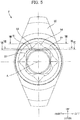
- Fig. 7 is a cross-sectional view of the anvil 5 taken along a plane that is positioned above the cross-sectional plane of Fig. 6 , is parallel to the flat surface portion 81, and passes through the second curved surface portion 94 (the plane passes along the line VII-VII in Fig. 5 ).
- the second curved surface portion 94 is positioned between the two cross-sectional parts of the first curved surface portions 93 in the circumferential direction (or the leftward/rightward direction).
- the second curved surface portion 94 is recessed rearward from connecting points X2 at which the second curved surface portion 94 is connected to the two cross-sectional parts of the first curved surface portion 93.
- radius of curvature of the second curved surface portion 94 may be uniform, or may be continuously changed.
- a relationship between the first curved surface portion 93 and the two uniform diameter surface portions 92 shown in Fig. 7 is the same as that shown in Fig. 6 . That is, the first curved surface portion 93 is recessed rearward from connecting points at which the first curved surface portion 93 is connected to the two cross-sectional parts of the uniform diameter surface portions 92.
- radius of curvature of the first curved surface portion 93 may be uniform, or may be continuously changed.
- Fig. 8 is a cross-sectional view of the anvil 5 taken along a plane that is positioned above the cross-sectional plane of Fig. 7 , is parallel to the flat surface portion 81, and passes through the second curved surface portion 94.
- the second curved surface portion 94 is positioned between the two cross-sectional parts of the sloped surface portion 91 in the circumferential direction (or the leftward/rightward direction).
- the second curved surface portion 94 is recessed rearward from connecting points X3 at which the sloped surface portion 91 is connected to the two cross-sectional parts of the uniform diameter surface portions 92.
- the socket 100 is formed with a front bore 100A and a rear bore 100B.
- the rear bore 100B is square shape in a rear view, in which the tip end portion 80 of the anvil 5 is configured to be received.
- the socket 100 is non-detachably attached to the anvil 5 by an engagement of a ball (not illustrated) provided in the socket with the anvil 5.
- the front bore 100A has a hexagonal shape configured to receive a fastener such as a bolt and a nut.
- the flat surface portion 81, the curved end portion 82, the first curved surface portion 93, and the second curved surface portion 94 of the anvil 5 are formed by machining a metallic member 55 having generally solid cylindrical shape employing a first end mill 130 and a second end mill 131.
- the cylindrical metallic member 55 has a first outer peripheral surface portion 55A corresponding to the sloped surface portion 91 and a second outer peripheral portion 55B corresponding to the uniform diameter surface portion 92 over an entire circumference.
- the first end mill 130 has a tip end portion having a rotation axis extending in the frontward/rearward direction, and the tip end portion has a tapered surface 130A whose diameter is gradually reduced toward its tip end (rearward).
- the second end mill 131 has a tip end portion having a tapered surface 131A whose diameter is gradually reduced toward its tip end.
- the tapered surface 131A has a tapering degree gentler than that of the tapered surface 130A toward the tip.
- the first outer peripheral surface portion 55A of the metallic member 55 is subjected to machining by the first end mill from the front end of the first outer peripheral surface portion 55A. Specifically, while position of the first end mill 130 in the upward/downward direction is maintained, the first end mill 130 is moved from its right end to its left end to form the flat surface portion 81. In this case, depth in the cutting direction (frontward/rearward direction) of the first end mill 130 is changed to form the curved end portion 82. That is, the first end mill 130 is moved so that cutting depth at the center portion in the leftward/rightward direction of the metallic member 55 becomes the largest.
- the first curved surface portion 93 is formed as a result of cutting by the tapered surface 130A. That is, in the cross-section parallel to the upward/downward direction and the frontward/rearward direction, the first curved surface portion 93 provides a sloped shape parallel to the tapered surface 130A of the first end mill 130.
- the second curved surface portion 94 is formed employing the second end mill 131.
- the second end mill 131 performs cutting to an upper side of the thus formed first curved surface portion 93 and the center portion in the leftward/rightward direction of the second outer peripheral surface portion 55B.
- depth in the cutting direction of the second end mill 131 is set greater than the depth in the cutting direction for forming the first curved surface portion 93.
- the second curved surface portion 94 is formed. That is, in the cross-section parallel to the upward/downward direction and the frontward/rearward direction, the first curved surface portion 93 provides a shape parallel to the tapered surface 130A of the first end mill 130.
- the anvil 5 is inserted in the rear bore 100B of the socket 100, and the user inserts the fastener such as the bolt in the front bore 100B of the socket 100.
- the fastener such as the bolt in the front bore 100B of the socket 100.
- the rotating hammer 47 is retracted against the urging force of the spring 43. At this time, the balls 43 move rearward in the grooves 41a. Then, engagement between the hammer 47 and the anvil 5 is released when the pawl 46B climbs over the blade 52, and the hammer 46 is released from the anvil 5. Then, elastic energy accumulated in the spring 43 is discharged, so that the hammer 47 rotationally moves frontward through the balls 42 relative to the spindle 41.
- one of the pawls 46B of the hammer 46 collides with one of the blades 52 of the anvil, and simultaneously, remaining one of the pawls 46B collides with remaining one of the blades 52, thereby engaging the hammer 46 and the anvil 5 with each other. Accordingly, impact force is imparted on the blade 52.
- the rotating hammer 46 is retracted against the urging force of the spring 43. Engagement between the hammer 46 and the anvil 5 is released when the pawl 46B climbs over the blade 52, and the hammer 46 is released from the anvil 5. Then, elastic energy accumulated in the spring 43 is discharged, so that the hammer 46 moves frontward. Hence, the pawls 46B again collide with the blades 52, so that rotational force of the hammer 46 and the spring 43 is transmitted to the anvil 5. In this way, the anvil 5 rotates together with the socket 100 attached to the tip end portion 80 by the rotational impact of the hammer 46. Therefore, the impact wrench 1 performs operation for fastening the fastener such as the screw and the bolt.
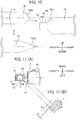
- Fig. 11 (A) is a plan view of the anvil 5.
- Fig. 11(B) is a cross-sectional view taken along the line XIB-BIB of Fig. 11(A) .
- the line XIB-BIB is a linear line inclined by 45 degrees in counterclockwise direction with respect to the frontward/rearward direction.
- This line is parallel to a direction of principal stress of a stress (hereinafter simply referred to as a distortion stress) generated at a left rear end portion PI of the flat surface portion 81 due to distortion of the anvil 5 during operation of the impact wrench 1.
- a distortion stress a stress generated at a left rear end portion PI of the flat surface portion 81 due to distortion of the anvil 5 during operation of the impact wrench 1.
- vertical impact stress applied to a portion ambient to the left rear end portion PI of the flat surface portion 81 is the largest stress among the vertical stress applied to the flat surface portion 81 during impact operation.
- the second curved surface portion 94 is not illustrated in Figs. 11(A) and 11(B) .
- the vertical impact stress is generated by the vertical component of force applied to the flat surface portion 81, the vertical component being perpendicular to the flat surface portion 81 when the socket 100 collides with the flat surface portion 81.
- Figs. 12(A) through 12(C) illustrate an anvil 205 according to a comparative example 1.
- the anvil 205 illustrated in Fig. 12(A) has a flat surface portion 205A instead of the first curved surface portion 93.
- the anvil 205 does not have the curved end portion 82 but has a liner end at a rear end of the flat surface portion.
- Fig. 12(B) is a cross-sectional view taken along the line XIIB-XIIB of Fig. 12(A) .
- the line XIIB-XIIB is a linear line inclined by 45 degrees in the counter clockwise direction with respect to the frontward/rearward direction.
- Fig. 12(C) is a cross-sectional view of the anvil 205 taken along the plane similar to the plane illustrated in Fig. 6 .
- the flat surface portion 205A has a linear shape on this cross section.
- the anvil 205 is produced by machining to the metallic member 55 by means of the first end mill 130 similar to the production of the anvil 5. However, for forming the flat surface portion, depth in the cutting direction of the first end mill 130 is maintained constant, so that the rear end of the flat surface portion can be linear in shape. With such a machining, the flat surface portion 205A is formed by the tapered surface 130A of the first end mill 130. Hence, the flat surface portion 205A of the anvil 205 is generally coincident with the tapered surface 130A in the cross-section taken along the plane (corresponding to the plane in Fig. 10 ) parallel to the frontward/rearward direction and the upward/downward direction.
- shape and length of the flat surface portion 205A are approximately the same as those of the first curved surface portion 93.
- the shape of the anvil 205 according to the comparative example 1 is the same as that of the anvil 5 other than the point described above.
- the first curved surface portion 93 illustrated in Fig. 11(B) has a length L1 in the direction of the line XIB-XIB (direction of principal stress) is greater than a length L2 illustrated in Fig. 12(B) of the flat surface portion in the direction of XIIB-XIIB (this direction is identical to the direction of XIB-XIB). Further, the first curved surface portion 93 has a radius of curvature larger than that of the flat surface portion. Hence, the anvil 5 can restrain stress concentration at the rear end portion PI of the left end portion of the flat surface portion 81 in comparison with the stress concentration occurring in the anvil 205.
- anvil 5 large displacement amount of the metallic material constituting the anvil 5 and positioned along the line XIB-XIB can be provided when the anvil 5 is distorted, since the second curved surface portion 94 is formed. Hence, force acting in the direction of principal stress can be escaped, thereby restraining stress concentration.
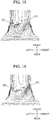
- Figs. 13 through 16 show analytical results of distributions of distortion stress with respect to the anvils according to the comparative examples 1 through 3 ( Figs. 13 through15), and the anvil 5 according to the present embodiment ( Fig. 16 ).
- the front end portion of the anvil 5 was fixed, while the rear end portion of the anvil 105 was applied with moment of 100N ⁇ m in the rotational direction R ( Fig. 3 ).
- the lines illustrated in Figs. 13 through 16 are iso-stress contours formed by connecting together the points having the same value of the principal stress component of the distortion stress generated under the above-described condition.
- the analyzed range shown in Figs. 13 through 16 is the range containing the flat surface portion of the anvil.
- Fig. 13 shows analytic result with respect to the anvil 205 according to the comparative example 1 illustrated in Figs. 12(A) and 12(B) .
- Fig. 14 shows analytic result with respect to the anvil according to the comparative example 2 where the first curved surface portion 93 was formed but the second curved surface portion 94 was not formed (In Fig. 11 , the second curved surface portion 94 is omitted for simplicity to facilitate explanation.
- the configuration of the comparative example 2 was the same as the configuration represented by Fig. 11 ).
- FIG. 15 shows analytic result with respect to the anvil according to the comparative example 3 where the second curved surface portion 94 was formed and the first curved surface portion was not formed, and the flat surface portion the same as the flat surface portion 205 was formed instead of the first curved surface portion 93.
- Fig. 16 shows analytic result with respect to the anvil 5 according to the present embodiment.
- the anvils according to the comparative examples 2 and 3 is the same as the anvil 5 except the points described above.
- Fig. 13 distortion stress with the maximum stress of 253MPa was generated at a region A.
- the reason A was the periphery in the flat surface portion (corresponding to the flat surface portion 81 of the present embodiment) and contained the portion corresponding to the left rear end portion PI of Fig. 12(A) . That is, in the anvil according to the comparative example 1, the region A provided maxim distortion stress and maximum vertical impact stress applied to the flat surface portion (corresponding to the flat surface portion 81 of the present embodiment). Therefore, the region A has a high degree of possibility of being a starting point toward breakage of the anvil.
- maximum distortion stress of 240MPa was generated at a region B.
- the region B was positioned adjacent to the left rear end portion PI. However, the region B had an area smaller than that of the region A. Further, the maximum stress of 240Ma was smaller than the maximum stress of 254MPa generated in the comparative example 1. In view of the foregoing, according to the analytic result, stress concentration occurring in the comparative example 2 is lesser than that occurring in the comparative example 1.
- maximum distortion stress of 243MPa was generated at a region C1. Further, the second highest distortion stress of 234MPa was generated at a region C2.
- the region C1 was positioned frontward and rightward of the regions A and B in Figs. 13 and 14 , respectively.
- the region C2 was positioned adjacent to the rear end portion PI of the left end portion. However, the region C2 had an area smaller than that of the region B. Further, the maximum distortion stress was smaller than the maximum stresses generated in the regions A and B.
- Analytic result with respect to the comparative example 3 reveals that concentration of distortion stress is restrained because of the second curved surface portion 94, and the portion where the maximum distortion stress is generated is shifted rightward and frontward of the portion where the vertical impact stress is generated.
- maximum distortion stress of 240MPa was generated at a region D1.
- the second highest distortion stress of 228MPa was generated at a region D2.
- the region D1 was positioned frontward and rightward of the regions A and B in Figs. 13 and 14 , respectively, and the region D1 had an area far smaller than that of the region C1.
- the region D2 contained a left region of a base end portion of the anvil. However, the distortion stress in the region D2 was lower than that in the regions A, B and C2.
- total value of the vertical impact stress and distortion stress in the region (substantially containing the region D2) where the maximum vertical impact stress is provided can be reduced, since the maximum value of the distortion stress is low and low distortion stress is provided in the region (substantially containing the region D2). That is, stress concentration occurring at a specific portion can be restrained. Accordingly, probability of damage to the anvil 5 can be lowered.
- an anvil 105 according to one modification will be described.
- like parts and components of the anvil 105 will be designated by the same reference numerals as those shown in the anvil 5 according to the above-described embodiment to avoid duplicating description.
- the anvil 105 includes a large diameter portion 51, a pair of blade portions 52, a tip end portion 180, and a connecting portion 190 for connecting together the large diameter portion 51 and the tip end portion 180.
- the tip end portion 180 is positioned at a front end of the large diameter portion 51.
- the tip end portion 180 has generally square shape in the front view to which the socket 100 ( Fig. 9 ) as the end bit is attachable.
- the front end portion 180 has four flat surface portions 181 each having generally square shape ( Fig. 5 ), and four corner portions 183 chamfered.
- the front end portion 180 is symmetrical about the axis A thorough rotation of every 90 degrees. Accordingly, the four flat surface portions 181 are symmetrically positioned about the axis A through rotation of 90 degrees. Neighboring two flat surface portions 181 are connected to each other by the corner portion 183.
- the corner portions 183 extend in the frontward/rearward direction.
- a curved end portion 182 is formed at a rear end of the flat surface portion 181.
- the curved end portion 182 has a shape recessed rearward. Specifically, the curved end portion 182 is positioned between two corner portions 183 (an upper left corner portion 183 and an upper right corner portion 183).
- the curved end portion 182 has a rearmost end positioned at a center point PC of the curved end portion in the leftward/rightward direction (the center point PC being positioned at equal distance from the two corner portions 183).
- the curved end portion 182 has a discontinuous curvature.
- the connecting portion 190 includes a sloped surface portion 191, four uniform diameter surface portions 192, four first curved surface portions 193A (as an example of a recessed portion and a first recessed portion), four first curved surface portions 193B (as an example of a recessed portion and a first recessed portion), and four second curved surface portions 194 (as an example of a recessed portion and a second recessed portion).
- the connecting portion 190 has rotational symmetries through every 90 degrees about the axis A.
- the four uniform diameter surface portions 192, the four first curved surface portions 193A, the four first curved surface portions 193B, and the four second curved surface portions 194 are respectively symmetrically positioned about the axis A through rotation of every 90 degrees.
- an uppermost first curved surface portion 193A, an uppermost first curved surface portion 193B, an uppermost second curved surface portion 194 connected to the uppermost first curved surface portions 193A, 193B, and two upper most uniform diameter surface portions 192 illustrated in Fig. 17 will only be described while omitting description as to remaining first curved surface portions 193A, 193B, remaining second curved surface portions 194, and remaining uniform diameter portions 192.
- the sloped surface portion 191 is generally cylindrical with its radius (a distance from the axis A to an outer peripheral surface of the sloped surface portion 191) gradually reduced in frontward direction.
- the sloped surface portion 191 has a rear end connected to a front end of the large diameter portion 51.
- the sloped surface portion 191 has a front end connected to a rear end of the uniform diameter surface portion 192 and a rear end of the second curved surface portion 194.
- the sloped surface portion 191 is inclined toward the axis A in the frontward direction.
- the uniform diameter surface portion 192 has a constant radius (from the axis A to an outer peripheral surface of the uniform diameter surface portion 92).
- the radius of the uniform diameter surface portion 192 is smaller than the radius of the large diameter portion 151 and not more than the radius of the sloped surface portion 191.
- Each uniform diameter surface portion 192 is at an angular position the same as that of a corner portion 183 in the circumferential direction.
- the uniform diameter surface portion 192 has a front end connected to the corner portion 183.
- the first curved surface portions 193A, 193B are positioned between two uniform diameter surface portions 192 in the leftward/rightward direction (or circumferential direction).
- Each of the first curved surface portions 193A, 193B has generally triangular shape, and is symmetric with each other with respect to a plane parallel to the front ward/rearward direction and the upward/downward direction and passing through the point PC.
- the first curved surface portion 193A is positioned rightward of the first curved surface portion 193B, and apexes of the first curved surface portions 193A and 193B are coincident with the point PC.
- the first curved surface portions 193A and 193B are at angular positions the same as that of the flat surface portion 81 in the circumferential direction.
- the first curved surface portions 193A and 193B have front ends in conformance with the curved end portion 182. That is, the front ends of the first curved surface portions 193A and 193B are in contact with the curved end portion 182.
- Fig. 20 is a cross-sectional view of the anvil 105 taken along a plane matching the flat surface portion 81 (the plane passing along the line XX-XX in Fig. 19 ).
- the first curved surface portion 193A has a right end (or one end in the circumferential direction) connected to the uniform diameter surface portion 192
- the first curved surface portion 193B has a left end (or another end in the circumferential direction) connected to the uniform diameter surface portion 192.
- the first curved surface portions 193A, 193B are recessed rearward from a connecting point X4 between the uniform diameter surface portion 192 and the first curved surface portions 193 and from another connecting point X4 between the uniform diameter surface portion 192 and the first curved surface portions 193.
- the radius of curvature of the single curved line is continuously changed. Incidentally, the radius of curvature may be changed discontinuously.
- the second curved surface portion 194 is recessed rearward, and has a generally sector shape surrounded by the sloped surface portion 191, the first curved surface portion 193A, and the first curved surface portion 193B.
- the second curved surface portion 194 has a rear end generally arcuate shaped, and is connected to the sloped surface portion 191.
- the second curved surface portion 194 has a front end having generally V-shape. An apex of the V-shape is coincident with the point PC. Remaining portion of the V-shape is connected to the first curved surface portions 193A, 193B.
- Fig. 21 is a cross-sectional view taken along a plane that is positioned above the cross-sectional plane of Fig. 20 , is parallel to the flat surface portion 81 ,and passes through the first curved surface portions 193A, 193B and the second curved surface portion 194 (the plane passes along the line XXI-XXI in Fig. 5 ).
- the second curved surface portion 194 is positioned between the first curved surface portion 193A and the first curved surface portion 193B in the circumferential direction (or the leftward/rightward direction).
- the second curved surface portion 194 has generally an arcuate shape recessed rearward from the first curved surface portions 193A, 193B.
- the second curved surface portion 194 is recessed rearward from connecting points X5 at which the first curved surface portions 193A and 193B are connected to the second curved surface portion 194.
- the first curved surface portions 193A, 193B are positioned rearward of the connecting points at which the uniform diameter surface portions 192 are connected to the first curved surface portions 193A, 193B.
- the second curved surface portion 194 is connected to the sloped surface portion 191. Similar to the cross-section illustrated in Fig. 8 pertaining to the above-described embodiment, the second curved surface portion 194 is positioned between the two cross-sectional parts of the sloped surface portion 191 in the circumferential direction (or the leftward/rightward direction). The second curved surface portion 194 is recessed rearward from connecting points at which the second curved surface portion 194 is connected to the two cross-sectional parts of the sloped surface portion 191.
- the anvil 105 is produced by machining a metallic member 55.
- the metallic member 55 has a first outer peripheral surface portion 55A corresponding to the sloped surface portion 191 and a second outer peripheral portion 55B corresponding to the uniform diameter surface portion 192.
- the first curved surface portions 193A, 193B are formed by cutting the metallic member 55 by means of a first end mill 130 in a manner similar to the formation of the first curved surface portion 93 according to the above embodiment. However, the first end mill 130 is moved so that the depth in the cutting direction is the deepest at a center portion in the leftward/rightward direction of the metallic member 55 in a manner to form the curved end portion 182.
- the first end mill 130 is moved so that depth in the cutting direction is deeper than the depth for forming the second curved surface portion 194. That is, the second end mill 131 is not employed, but only the first end mill 130 is used for forming the first curved surface portions 193A, 193B and the second curved surface portion 194.
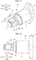
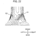
- Fig. 22 shows analytic result showing distribution of distortion stress generated in the anvil 105.
- Condition for the analysis was the same as the condition employed in connection with Figs. 13 through 16 .
- maximum distortion stress of 248MPa was generated at a region E1.
- second highest distortion stress of 235MPa was generated at a region E2.
- the region E1 was positioned frontward and rightward of the regions A in Fig. 13 , and the region E1 was at a position different from the region A where maximum vertical impact stress was distributed.
- the region E1 had an area smaller than that of the region A.
- the value of the distortion stress at the region E1 was lower than that at the region A.
- the region E2 contained a region that is left end portion of a base end portion of the anvil (The region E2 corresponds to the region containing the rear end portion PI of the left end portion in Fig. 12 ). However, the distortion stress applied to the region E2 was lower than that applied to the region A.
- the impact tool according to the present invention is not limited to the above-described embodiments, but various changes and improvements may be made within a scope of claims.
- the second curved surface portion 94 may not be formed in the anvil 5 according to the embodiment.
- reduction in distortion stress can be achieved by the formation of the first curved surface portion 93 as understood from the analytic result shown in Fig. 14 .
- the first curved surface portion 93 may not be formed in the anvil 5.
- the second curved surface portion 94 is formed as understood from the analytic result shown in Fig. 14 , distortion stress can be reduced and the portion at which the maximum stress is generated due to distortion can be displaced from the portion at which the maximum stress is generated due to impacting operation.
- first curved surface portions 193A, 193B and the second curved surface portion 194 may not be formed in the modified embodiment.
- the first curved surface portion 93 and the second curved surface portion 94 have common configuration in that the first curved surface portion 93 and the second curved surface portion 94 are recessed rearward (in an axial direction and directing from the tip end portion 80 toward the large diameter portion 51 as a base end portion) of the anvil 5.
- the first curved surface portion 93 and the second curved surface portion 94 have recessed shapes recessed from the portion connected to the outward portion thereof (the outward portion being the uniform diameter surface portion 92 which is outward of the first curved surface portion 93, or being the uniform diameter surface portion 92 or the sloped surface portion 91 which are outward of the second curved surface portion 94). That is, the connecting portion 90 should have a curved surface recessed rearward (in the axial direction).
- the anvil 5 may have a configuration such that the inward surface is recessed from at least a part of an outward surface outward of the inward surface in the circumferential direction.
- the first curved surface portion 93 and the second curved surface portion 94 have generally arcuate shape. However, these portions may not have the generally arcuate shape as long as these have curved lines recessed rearward, such as parabolic curve.
- the second curved surface portion 94 is not contacted with the flat surface portion 81. However, a part of the second curved surface portion 94 may be in contact with the flat surface portion 81.
- the rotation axis of the rotor 22 of the motor 2 is coaxial with the axis A of the large diameter portion 51 of the anvil 5.
- the rotation axis and the axis A may be displaced from each other in the frontward/rearward direction or in the leftward/rightward direction.
- the first curved surface portion 93 has a shape approximately coincident with the tapered surface 130A of the first end mill 130
- the second curved surface portion 94 has a shape approximately coincident with the tapered surface 131A of the second end mill 131.
- the first curved surface portion 93 and the second curved surface portion 94 may have a shape other than the above.
- the first curved surface portion 93 and the second curved surface portion 94 may have generally arcuate shape recessed rearward.
Landscapes
- Engineering & Computer Science (AREA)
- Mechanical Engineering (AREA)
- Portable Power Tools In General (AREA)
Abstract
Description
- The present invention relates to a power tool provided with an impact mechanism.
- Conventionally, an impact tool such as an impact driver and an impact wrench is known as an electric power tool where rotation of a motor is converted to a rotational impacting force through an impact mechanism and the force is transmitted to an end bit.
- For example, Patent Literature PTL1 discloses an impact tool provided with an impact mechanism including a hammer rotatable by the rotational driving force from a motor, and an anvil having an attachment portion to which an end bit is attached. The hammer drivingly rotated by the motor rotationally impacts the anvil. Operation for fastening a fastener such as a screw and a bolt is performed by the rotation of the end bit attached to the attachment portion.
- [PTL 1]
Japanese Patent Application Publication No.2014-140930 - However, according to the conventional impact tool, stress concentration occurs at a particular portion of the anvil when large torque is generated during fastening operation, and damage to the anvil may occur starting from the stress concentrating portion.
- Therefore, it is an object of the present invention to provide an electric power tool provided with an anvil capable of restraining stress concentration.
- In order to attain the above-described object, the present invention provides a power tool. The electric power tool includes a housing, a motor, an anvil and an impact mechanism. The motor is accommodated in the housing and rotatable. The anvil is supported by the housing and rotatable about an axis. The impact mechanism is configured to convert a rotational force generated by the motor into a rotational impact force about the axis, and to apply the rotational impact force to the anvil. The anvil includes a base portion, an end bit attachment portion, and a connecting portion. The base portion is rotatably supported by the housing. An end bit is attachable to the end bit attachment portion. The end bit attachment portion has a flat surface portion. The connecting portion integrally connects together the base portion and the end bit attachment portion. The connecting portion has a diameter gradually reduced, in a direction from the base portion toward the end bit attachment portion. The connecting portion is formed with a recessed portion. The connecting portion has an outer peripheral surface portion where the recessed portion is formed. The recessed portion is recessed, in an axial direction from the end bit attachment portion toward the base portion, from a point where the recessed portion is connected to the outer peripheral surface portion in a cross-section taken along a plane parallel to the flat surface portion and passing through the recessed portion.
- According to the power tool described above, since the recessed portion is formed, concentration of stress on a specific point of the anvil can be restrained.
- Preferably, the recessed portion is in contact with the flat surface portion. Or, preferably, the recessed portion is separated from the flat surface portion.
- Preferably, the recessed portion includes a first recessed portion in contact with the flat surface portion, and a second recessed portion separated from the flat surface portion.
- Preferably, the recessed portion has a curved-line shape recessed in the axial direction in the cross-section. Preferably, the connecting portion has an outer peripheral surface portion where the recessed portion is formed. The recessed portion is recessed, in an axial direction, from a point where the recessed portion is connected to the outer peripheral surface portion in a cross-section taken along a plane parallel to the flat surface portion and passing through the recessed portion. Preferably, the recessed portion has a curved-line shape recessed in the axial direction in the cross-section. Preferably, the recessed portion has an arcuate shape recessed in the axial direction in the cross-section. Preferably, the recessed portion has a parabolic-curve shape recessed in the axial direction in the cross-section.
- According to the present invention, the electric power tool including the anvil capable of restraining stress concentration can be provided.
-
- [
Fig. 1 ]
Fig. 1 is an external view illustrating an impact wrench according to an embodiment of the present invention; - [
Fig. 2 ]
Fig. 2 is a cross-sectional view of the impact wrench according to the embodiment of the present invention; - [
Fig. 3 ]
Fig. 3 is a perspective view of an anvil provided in the impact wrench according to the embodiment of the present invention; - [
Fig. 4 ]
Fig. 4 is a side view of the anvil according to the embodiment of the present invention; - [
Fig. 5 ]
Fig. 5 is a front view of the anvil according to the embodiment of the present invention; - [
Fig. 6 ]
Fig. 6 is a cross-sectional view of the anvil taken along a line VI-VI ofFig. 5 according to the embodiment of the present invention; - [
Fig. 7 ]
Fig. 7 is a cross-sectional view of the anvil taken along a line VII-VII ofFig. 5 according to the embodiment of the present invention; - [
Fig. 8 ]
Fig. 8 is a cross-sectional view of the anvil taken along a line VIII-VIII ofFig. 5 according to the embodiment of the present invention; - [
Fig. 9 ]
Fig. 9 is a cross-sectional view of the anvil according to the embodiment of the present invention and a socket attached to the anvil; - [
Fig. 10 ]
Fig. 10 is a view for description of a method of producing the anvil according to the embodiment of the present invention; - [
Fig. 11 ]
Fig. 11 is a view illustrating the anvil according to the embodiment of the present invention, where (A) is a plan view of the anvil, (B) is a cross-sectional view taken along a line XIB-XIB of (A); - [
Fig. 12 ]
Fig. 12 is a view illustrating an anvil according to a comparative example 1, where (A) is a plan view of the anvil, (B) is a cross-sectional view taken along a line XIIB-XIIB of (A), and (C) is a cross-sectional view of the anvil taken along a plane similar toFig. 6 ; - [
Fig. 13 ]
Fig. 13 is a graph representing stress distribution in the anvil according to the comparative example 1; - [
Fig. 14 ]
Fig. 14 is a graph representing stress distribution in an anvil according to a comparative example 2; - [
Fig. 15 ]
Fig. 15 is a graph representing stress distribution in an anvil according to a comparative example 3; - [
Fig. 16 ]
Fig. 16 is a graph representing stress distribution in the anvil according to the embodiment of the present invention; - [
Fig. 17 ]
Fig. 17 is a perspective view of an anvil according to a modification; - [
Fig. 18 ]
Fig. 18 is a side view of the anvil according to the modification; - [
Fig. 19 ]
Fig. 19 is a front view of the anvil according to the modification; - [
Fig. 20 ]
Fig. 20 is a cross-sectional view of the anvil taken along a line XX-XX ofFig. 19 according to the modification; - [
Fig. 21 ]
Fig. 21 is a cross-sectional view of the anvil taken along a line XXI-XXI ofFig. 19 according to the modification; and - [
Fig. 22 ]
Fig. 22 is a graph representing stress distribution in the anvil according to the modification. - An
impact wrench 1 as an example of an electric power tool according to an embodiment of the present invention will be described with reference toFigs. 1 through 5 . Theimpact wrench 1 is an electrically powered power tool for fastening a fastener (such as a bolt and a screw) to a workpiece (such as steel and wood). - In the following description, directions of "upward", "downward", "frontward", and "rearward" will be defined on a basis of
Fig. 1 . Further, directions of "rightward" and "leftward" will be defined when the impact wrench is observed frontward from behind. Further in reference to dimension, numerical value, and shape, etc. not only completely identical dimension, completely identical numerical value, and completely identical shape, but also approximately the same dimension, approximately the same numerical value, and approximately the same shape due to production error should be within the meanings of these words. Similarly, the terms "identical", "perpendicular", "parallel", "coincident", and "flush with", and etc. should be construed to encompass the meanings of "approximately the same", "approximately perpendicular", "approximately parallel", "generally coincident", and "approximately flush with". - The
impact wrench 1 illustrated inFigs. 1 and2 is an electrically powered fastening tool. As illustrated inFig. 2 , theimpact wrench 1 includes amotor 2, agear mechanism 3, animpact mechanism 4, ananvil 5, acontroller 6, and abattery pack 73. - As illustrated in
Figs. 1 and2 , theimpact wrench 1 has: an outer shell including ahousing 7 accommodating therein themotor 2; ahammer case 8 accommodating therein thegear mechanism 3 and theimpact mechanism 4; and acover 8 covering an outer peripheral surface of thehammer case 8. - The
housing 7 is made from resin, and includes abarrel portion 71 and ahandle portion 72. Thebarrel portion 71 is generally hollow cylindrical. Thebarrel portion 71, in cooperation with thehammer case 8, accommodates therein themotor 2, thegear mechanism 3, theimpact mechanism 4, and theanvil 5 arrayed in this order in the frontward direction. - The
handle portion 72 extends downward from a front end portion of a lower surface of thebarrel portion 71. Thehandle portion 72 is integral with thebarrel portion 71. - The
hammer case 8 is made from aluminum, and is positioned frontward of thebarrel portion 71, and generally hollow cylindrical. Thehammer case 8 includes a reduceddiameter portion 801. - The reduced
diameter portion 801 is generally hollow cylindrical and extends in the frontward/rearward direction. The reduceddiameter portion 801 has an inner peripheral surface to which a bearingmetal 10 is fixed by force-fitting. The reduceddiameter portion 801 has a front end portion forming an opening. - The
cover 9 is made from resin, and is positioned to cover a front end portion of an outer peripheral surface of thehammer case 8. Thecover 9 has a front end portion forming an opening. - As illustrated in
Fig. 2 , themotor 2 is a brushless motor including arotation shaft 21, arotor 22, astator 23, and afan 24. - The
rotation shaft 21 extends in the frontward/rearward direction, and is rotatably supported by thebarrel portion 71 through a bearing. - The
rotor 22 includes a plurality of permanent magnets not illustrated, and extends in the frontward/rearward direction. Therotor 22 is fixed to therotation shaft 21 to rotate integrally therewith. - The
stator 23 includes a plurality of stator windings not illustrated. Thestator 23 is fixed to thebarrel portion 71 to surround therotor 22. - The
fan 24 is provided at therotation shaft 21 and is positioned frontward of a front surface of therotor 22. Thefan 24 is fixed to therotation shaft 21 to rotate integrally therewith. - As illustrated in
Fig. 2 , thegear mechanism 3 includes apinion gear 31 positioned at a front end portion of therotation shaft 21 of themotor 2, a pair ofgears 32 in meshing engagement with thepinion gear 31, and an outer gear (not illustrated) in meshing engagement with thegears 32. Thegear mechanism 3 is a planetary gear mechanism where thepinion gear 31 functions as a sun gear and the pair ofgears 32 functions as planetary gears. Thegear mechanism 3 is configured so that the rotation of thepinion gear 31 is deceleratingly transmitted to theimpact mechanism 4. - As illustrated in
Figs. 1 through 3 , theimpact mechanism 4 includes aspindle 41,balls 42, aspring 43, and ahammer 46. - The
spindle 41 has an outer peripheral surface formed with twogrooves 41a having generally V-shape. Theballs 42 are positioned at thegrooves 41a so as to be movable along thegrooves 41a in the frontward/rearward direction. Thespring 43 is a coil spring disposed over thespindle 41. Thespring 43 has an annular shape in the front view. Thespindle 41 has a tip end portion forming a protrudingportion 41C. - The
spring 43 has a front end portion in abutment with thehammer 46 for urging thehammer 46 frontward. Thespring 43 has a rear end portion in abutment with thespindle 41. - As illustrated in
Fig. 2 , thehammer 46 is positioned in thehammer case 8 and is rotatable about an axis A extending in the frontward/rearward direction. Thehammer 46 includes abody portion 46A and a pair ofpawls 46B (as indicated by dotted line inFig. 2 ). The axis A is coincident with the rotation axis of therotor 22. - The
body portion 46A has an inner peripheral surface formed with twogrooves 46e extending in the frontward/rearward direction and recessed radially outwardly. Eachgroove 46e is positioned in confrontation with eachgroove 41a of thespindle 41 so as to support theballs 42 in cooperation with thegroove 41a. Hence, thehammer 46 is movable relative to thespindle 41 in the frontward/rearward direction and a circumferential direction. The pair ofpawls 46B protrudes frontward from a front surface of thebody portion 46A. - As illustrated in
Figs. 1 through 3 , theanvil 5 is positioned in thehammer case 8, and includes a large diameter portion 51 (as an example of a base portion), a pair ofblade portions 52, a tip end portion 80 (as an example of an end bit attachment portion), and a connecting portion 90 (as an example of a connecting portion) for integrally connecting together thelarge diameter portion 51 and thetip end portion 80. - The
large diameter portion 51 extends in the frontward/rearward direction, and has a front end portion fittingly inserted in the bearingmetal 10 so as to be supported by the bearingmetal 10 and rotatable about the axis A. Thelarge diameter portion 51 is formed with anengagement groove 5a (Fig. 2 ) extending in the frontward/rearward direction. The protrudingportion 41C of thespindle 41 is fixed to theengagement groove 5a by force-fitting. - The
blade portions 52 are integral with thelarge diameter portion 51. Theblade portions 52 are positioned opposite to each other with respect to the axis A in a diametrical direction of theanvil 5. - The
tip end portion 80 is provided at a front end of thelarge diameter portion 51, and is exposed to an outside through the openings of thehammer case 8 and thecover 9. A socket 100 (Fig. 10 ) as an end bit is attachable to thetip end portion 80. Details of theanvil 5 will be described later. - As illustrated in
Figs. 1 and2 , thecontroller 6 includes atrigger 63, and acircuit board 64. Thetrigger 63 is positioned at a front upper end portion of thehandle portion 72. Thetrigger 63 is connected to aswitch mechanism 61. - The
switch mechanism 61 is accommodated within thehandle portion 72. Theswitch mechanism 61 is configured to output to the circuit board 64 a tool start-up signal to energize themotor 2 in response to start-up operation (dragging operation) of thetrigger 63, and to terminate output of the tool start-up signal in response to release of the dragging operation to thetrigger 63, that is, in response to stopping operation. - The
circuit board 64 is accommodated in a lower portion of thehandle portion 72. Thecircuit board 64 includes switching elements not illustrated. Thecircuit board 64 is configured to alter switching operation made by the switching elements through the adjustment of electrical energy to be supplied to themotor 2 in accordance with dragging amount of thetrigger 63, so as to control rotation speed of themotor 2. - The
battery pack 73 contains a secondary battery not illustrated, and is attachable to and detachable from a lower end of thehandle portion 72. Electric power from the secondary battery is supplied to thecontroller 6 and themotor 2. - Details of the
anvil 5 will be described. As illustrated inFigs. 3 through 5 , thelarge diameter portion 51 is generally solid cylindrical that is coaxial with the axis A. Thetip end portion 80 has generally square shape in the front view to which the socket 100 (Fig. 9 ) as the end bit is attachable. Specifically, thefront end portion 80 has fourflat surface portions 81 each having generally square shape (Fig. 5 ) extending in the frontward/rearward direction, and fourcorner portions 83 chamfered and connecting neighboring twoflat surfaces 81 together. Thefront end portion 80 is symmetrical about the axis A through rotation of every 90 degrees. Accordingly, the fourflat surface portions 81 are symmetrically positioned about the axis A through rotation of 90 degrees. That is, using one specificflat surface portion 81 as a base, remaining threeflat surface portions 81 are positioned at angularly 90 degrees, 180 degrees, and 270 degrees away from the specificflat surface portion 81. Thecorner portions 83 extend in the frontward/rearward direction. - In the following description, an uppermost
flat surface portion 81 among the fourflat surfaces 81 illustrated inFig. 3 will be described. As described above, since the fourflat surface portions 81 are symmetrically positioned about the axis A through rotation of every 90 degrees, configuration of the fourflat surface portions 81 are identical to one another. Therefore, description as to the remainingflat surface portions 81 will be omitted. - A
curved end portion 82 is formed at a rear end of theflat surface portion 81. Thecurved end portion 82 is positioned between two corner portions 83 (anupper corner portion 83 and alower corner portion 83 inFig. 6 ) and has a shape recessed rearward. Specifically, thecurved end portion 82 has a generally arcuate shape having a rearmost portion positioned at a center of the curved end portion in a leftward/rightward direction. Thecurved end portion 82 has a continuous and smooth profile. In other words, thecurved end portion 82 may have a constant radius of curvature or have a curvature whose radius is continuously changed. - The connecting
portion 90 includes a slopedsurface portion 91, four uniformdiameter surface portions 92, four first curved surface portions 93 (as an example of a recessed portion and a first recessed portion), and four second curved surface portions 94 (as an example of a recessed portion and a second recessed portion). The connectingportion 90 is symmetrical about the axis through rotation of every 90 degrees. Accordingly, the four uniformdiameter surface portions 92, the four firstcurved surface portions 93, and the four secondcurved surface portions 94 are respectively symmetrically positioned about the axis A through rotation of every 90 degrees. In the following description, an uppermost firstcurved surface portion 93 illustrated inFig. 3 , an uppermost secondcurved surface portion 94 connected to the uppermost firstcurved surface portion 93, and uppermost two uniformdiameter surface portions 92 will be described while omitting description as to remaining firstcurved surface portions 93, remaining secondcurved surface portions 94, and remaininguniform diameter portions 92. - The sloped
surface portion 91 is generally cylindrical with its radius (a distance from the axis A to an outer peripheral surface of the sloped surface portion 91) gradually reduced in frontward direction. The slopedsurface portion 91 has a rear end whose radius is coincident with a radius of thelarge diameter portion 51, and has a front end whose radius is coincident with a radius of the uniformdiameter surface portion 92. The rear end of the slopedsurface portion 91 is connected to the front end of thelarge diameter portion 51. The front end of the slopedsurface portion 91 is connected to the rear ends of the uniformdiameter surface portions 92 and rear ends of the secondcurved surface portions 94. - The uniform
diameter surface portion 92 has a constant radius (from the axis A to an outer peripheral surface of the uniform diameter surface portion 92). The radius is smaller than the radius of thelarge diameter portion 51 and not more than the radius of the slopedsurface portion 91. Each uniformdiameter surface portion 92 is at an angular position the same as that of acorner portion 83 in the circumferential direction. The uniformdiameter surface portion 92 has a front end connected to thecorner portion 83. - The first
curved surface portion 93 is positioned between two uniformdiameter surface portions 92 in the circumferential direction. The firstcurved surface portion 93 is at an angular position the same as that of theflat surface portion 81 in the circumferential direction. The firstcurved surface portion 93 has a front end in conformance with thecurved end portion 82. That is, the front end of the slopedsurface portion 91 is in contact with thecurved end portion 82. - The first
curved surface portion 93 is recessed rearward. This configuration will be described in detail.Fig. 6 is a cross-sectional view of theanvil 5 taken along a plane parallel to theflat surface portion 81 and passing through the first curved surface portion 93 (the plane passes along the line VI-VI inFig. 5 ). In the cross-section illustrated inFig. 6 , the firstcurved surface portion 93 is positioned between two cross-sectional parts of the uniformdiameter surface portions 92 in the circumferential direction (or the leftward/rightward direction). The firstcurved surface portion 93 is recessed rearward from connecting points X1 at which the firstcurved surface portion 93 is connected to the two cross-sectional parts of the uniformdiameter surface portions 92. In the cross-section, radius of curvature of the firstcurved surface portion 93 may be uniform, or may be continuously changed. - As illustrated in
Fig. 3 , the secondcurved surface portion 94 is recessed rearward, and has a generally sector shape surrounded by the slopedsurface portion 91, the uniformdiameter surface portion 92, and the firstcurved surface portion 93. Specifically, the secondcurved surface portion 94 has a front end having generally arcuate shape and connected to a rear end of the firstcurved surface portion 93. The secondcurved surface portion 94 has a rear end portion generally V-shaped. The V-shaped rear end portion of the secondcurved surface portion 94 has a front end portion connected to the uniformdiameter surface portion 92, and has a remaining rear end portion connected to a rear end portion of the slopedsurface portion 91. -
Fig. 7 is a cross-sectional view of theanvil 5 taken along a plane that is positioned above the cross-sectional plane ofFig. 6 , is parallel to theflat surface portion 81, and passes through the second curved surface portion 94 (the plane passes along the line VII-VII inFig. 5 ). In the cross-section illustrated inFig. 7 , the secondcurved surface portion 94 is positioned between the two cross-sectional parts of the firstcurved surface portions 93 in the circumferential direction (or the leftward/rightward direction). The secondcurved surface portion 94 is recessed rearward from connecting points X2 at which the secondcurved surface portion 94 is connected to the two cross-sectional parts of the firstcurved surface portion 93. In the cross-section, radius of curvature of the secondcurved surface portion 94 may be uniform, or may be continuously changed. A relationship between the firstcurved surface portion 93 and the two uniformdiameter surface portions 92 shown inFig. 7 is the same as that shown inFig. 6 . That is, the firstcurved surface portion 93 is recessed rearward from connecting points at which the firstcurved surface portion 93 is connected to the two cross-sectional parts of the uniformdiameter surface portions 92. In this cross-section shown inFig. 7 , radius of curvature of the firstcurved surface portion 93 may be uniform, or may be continuously changed. -
Fig. 8 is a cross-sectional view of theanvil 5 taken along a plane that is positioned above the cross-sectional plane ofFig. 7 , is parallel to theflat surface portion 81, and passes through the secondcurved surface portion 94. In the cross-section illustrated inFig. 8 , the secondcurved surface portion 94 is positioned between the two cross-sectional parts of the slopedsurface portion 91 in the circumferential direction (or the leftward/rightward direction). The secondcurved surface portion 94 is recessed rearward from connecting points X3 at which the slopedsurface portion 91 is connected to the two cross-sectional parts of the uniformdiameter surface portions 92. - As illustrated in
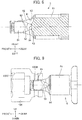
Fig. 9 , thesocket 100 is formed with afront bore 100A and arear bore 100B. Therear bore 100B is square shape in a rear view, in which thetip end portion 80 of theanvil 5 is configured to be received. Thesocket 100 is non-detachably attached to theanvil 5 by an engagement of a ball (not illustrated) provided in the socket with theanvil 5. Thefront bore 100A has a hexagonal shape configured to receive a fastener such as a bolt and a nut. - As illustrated in
Fig. 10 , theflat surface portion 81, thecurved end portion 82, the firstcurved surface portion 93, and the secondcurved surface portion 94 of theanvil 5 are formed by machining ametallic member 55 having generally solid cylindrical shape employing afirst end mill 130 and asecond end mill 131. The cylindricalmetallic member 55 has a first outerperipheral surface portion 55A corresponding to the slopedsurface portion 91 and a second outerperipheral portion 55B corresponding to the uniformdiameter surface portion 92 over an entire circumference. - Here, the
first end mill 130 has a tip end portion having a rotation axis extending in the frontward/rearward direction, and the tip end portion has a taperedsurface 130A whose diameter is gradually reduced toward its tip end (rearward). Further, thesecond end mill 131 has a tip end portion having a taperedsurface 131A whose diameter is gradually reduced toward its tip end. Here, thetapered surface 131A has a tapering degree gentler than that of the taperedsurface 130A toward the tip. - For producing the
anvil 5, firstly, the first outerperipheral surface portion 55A of themetallic member 55 is subjected to machining by the first end mill from the front end of the first outerperipheral surface portion 55A. Specifically, while position of thefirst end mill 130 in the upward/downward direction is maintained, thefirst end mill 130 is moved from its right end to its left end to form theflat surface portion 81. In this case, depth in the cutting direction (frontward/rearward direction) of thefirst end mill 130 is changed to form thecurved end portion 82. That is, thefirst end mill 130 is moved so that cutting depth at the center portion in the leftward/rightward direction of themetallic member 55 becomes the largest. By such cutting operation to the metalingmember 55 while moving thefirst end mill 130, the firstcurved surface portion 93 is formed as a result of cutting by the taperedsurface 130A. That is, in the cross-section parallel to the upward/downward direction and the frontward/rearward direction, the firstcurved surface portion 93 provides a sloped shape parallel to the taperedsurface 130A of thefirst end mill 130. - Then, the second
curved surface portion 94 is formed employing thesecond end mill 131. At this time, thesecond end mill 131 performs cutting to an upper side of the thus formed firstcurved surface portion 93 and the center portion in the leftward/rightward direction of the second outerperipheral surface portion 55B. In this case, depth in the cutting direction of thesecond end mill 131 is set greater than the depth in the cutting direction for forming the firstcurved surface portion 93. Hence, the secondcurved surface portion 94 is formed. That is, in the cross-section parallel to the upward/downward direction and the frontward/rearward direction, the firstcurved surface portion 93 provides a shape parallel to the taperedsurface 130A of thefirst end mill 130. - Next, fastening operation employing the
impact wrench 1 according to the embodiment of the present invention will be described. - Firstly, the
anvil 5 is inserted in therear bore 100B of thesocket 100, and the user inserts the fastener such as the bolt in thefront bore 100B of thesocket 100. Upon rotation of thespindle 41 by themotor 2, theballs 42, thehammer 46, and theanvil 5 are rotated together with thespindle 41 to start fastening operation to the fastener. - In accordance with an increase in load applied to the anvil due to progress in the fastening operation, the rotating hammer 47 is retracted against the urging force of the
spring 43. At this time, theballs 43 move rearward in thegrooves 41a. Then, engagement between the hammer 47 and theanvil 5 is released when thepawl 46B climbs over theblade 52, and thehammer 46 is released from theanvil 5. Then, elastic energy accumulated in thespring 43 is discharged, so that the hammer 47 rotationally moves frontward through theballs 42 relative to thespindle 41. Hence, one of thepawls 46B of thehammer 46 collides with one of theblades 52 of the anvil, and simultaneously, remaining one of thepawls 46B collides with remaining one of theblades 52, thereby engaging thehammer 46 and theanvil 5 with each other. Accordingly, impact force is imparted on theblade 52. - After the collision of the
pawls 46B with theblades 52, therotating hammer 46 is retracted against the urging force of thespring 43. Engagement between thehammer 46 and theanvil 5 is released when thepawl 46B climbs over theblade 52, and thehammer 46 is released from theanvil 5. Then, elastic energy accumulated in thespring 43 is discharged, so that thehammer 46 moves frontward. Hence, thepawls 46B again collide with theblades 52, so that rotational force of thehammer 46 and thespring 43 is transmitted to theanvil 5. In this way, theanvil 5 rotates together with thesocket 100 attached to thetip end portion 80 by the rotational impact of thehammer 46. Therefore, theimpact wrench 1 performs operation for fastening the fastener such as the screw and the bolt. - In the
anvil 5 according to the present embodiment, concentration of stress applied to theanvil 5 during fastening operation can be reduced by thecurved end portion 82 and the firstcurved surface portion 93 continuous with thecurved end portion 82. This point will be described with reference toFigs. 11(A) through 12(C) .Fig. 11 (A) is a plan view of theanvil 5.Fig. 11(B) is a cross-sectional view taken along the line XIB-BIB ofFig. 11(A) . The line XIB-BIB is a linear line inclined by 45 degrees in counterclockwise direction with respect to the frontward/rearward direction. This line is parallel to a direction of principal stress of a stress (hereinafter simply referred to as a distortion stress) generated at a left rear end portion PI of theflat surface portion 81 due to distortion of theanvil 5 during operation of theimpact wrench 1. Incidentally, at the impact operation in a case where theanvil 5 rotates in a rotating direction R (Fig. 3 ), vertical impact stress applied to a portion ambient to the left rear end portion PI of theflat surface portion 81 is the largest stress among the vertical stress applied to theflat surface portion 81 during impact operation. For the simplicity, the secondcurved surface portion 94 is not illustrated inFigs. 11(A) and 11(B) . Here, the vertical impact stress is generated by the vertical component of force applied to theflat surface portion 81, the vertical component being perpendicular to theflat surface portion 81 when thesocket 100 collides with theflat surface portion 81. -
Figs. 12(A) through 12(C) illustrate ananvil 205 according to a comparative example 1. Theanvil 205 illustrated inFig. 12(A) has aflat surface portion 205A instead of the firstcurved surface portion 93. Theanvil 205 does not have thecurved end portion 82 but has a liner end at a rear end of the flat surface portion.Fig. 12(B) is a cross-sectional view taken along the line XIIB-XIIB ofFig. 12(A) . The line XIIB-XIIB is a linear line inclined by 45 degrees in the counter clockwise direction with respect to the frontward/rearward direction.Fig. 12(C) is a cross-sectional view of theanvil 205 taken along the plane similar to the plane illustrated inFig. 6 . Theflat surface portion 205A has a linear shape on this cross section. - The
anvil 205 is produced by machining to themetallic member 55 by means of thefirst end mill 130 similar to the production of theanvil 5. However, for forming the flat surface portion, depth in the cutting direction of thefirst end mill 130 is maintained constant, so that the rear end of the flat surface portion can be linear in shape. With such a machining, theflat surface portion 205A is formed by the taperedsurface 130A of thefirst end mill 130. Hence, theflat surface portion 205A of theanvil 205 is generally coincident with thetapered surface 130A in the cross-section taken along the plane (corresponding to the plane inFig. 10 ) parallel to the frontward/rearward direction and the upward/downward direction. That is, in the cross-section, shape and length of theflat surface portion 205A are approximately the same as those of the firstcurved surface portion 93. The shape of theanvil 205 according to the comparative example 1 is the same as that of theanvil 5 other than the point described above. - The first
curved surface portion 93 illustrated inFig. 11(B) has a length L1 in the direction of the line XIB-XIB (direction of principal stress) is greater than a length L2 illustrated inFig. 12(B) of the flat surface portion in the direction of XIIB-XIIB (this direction is identical to the direction of XIB-XIB). Further, the firstcurved surface portion 93 has a radius of curvature larger than that of the flat surface portion. Hence, theanvil 5 can restrain stress concentration at the rear end portion PI of the left end portion of theflat surface portion 81 in comparison with the stress concentration occurring in theanvil 205. - Further, in the
anvil 5 according to the present embodiment, large displacement amount of the metallic material constituting theanvil 5 and positioned along the line XIB-XIB can be provided when theanvil 5 is distorted, since the secondcurved surface portion 94 is formed. Hence, force acting in the direction of principal stress can be escaped, thereby restraining stress concentration. - The above-described effect will be described in more detail.
Figs. 13 through 16 show analytical results of distributions of distortion stress with respect to the anvils according to the comparative examples 1 through 3 (Figs. 13 through15), and theanvil 5 according to the present embodiment (Fig. 16 ). In the analysis, in order to evaluate stress generated due to simple distortion, the front end portion of theanvil 5 was fixed, while the rear end portion of theanvil 105 was applied with moment of 100N·m in the rotational direction R (Fig. 3 ). (This was the condition for the analysis). The lines illustrated inFigs. 13 through 16 are iso-stress contours formed by connecting together the points having the same value of the principal stress component of the distortion stress generated under the above-described condition. Further, the analyzed range shown inFigs. 13 through 16 is the range containing the flat surface portion of the anvil. -
Fig. 13 shows analytic result with respect to theanvil 205 according to the comparative example 1 illustrated inFigs. 12(A) and 12(B) .Fig. 14 shows analytic result with respect to the anvil according to the comparative example 2 where the firstcurved surface portion 93 was formed but the secondcurved surface portion 94 was not formed (InFig. 11 , the secondcurved surface portion 94 is omitted for simplicity to facilitate explanation. The configuration of the comparative example 2 was the same as the configuration represented byFig. 11 ).Fig. 15 shows analytic result with respect to the anvil according to the comparative example 3 where the secondcurved surface portion 94 was formed and the first curved surface portion was not formed, and the flat surface portion the same as theflat surface portion 205 was formed instead of the firstcurved surface portion 93.Fig. 16 shows analytic result with respect to theanvil 5 according to the present embodiment. Incidentally, the anvils according to the comparative examples 2 and 3 is the same as theanvil 5 except the points described above. - As shown in
Fig. 13 , distortion stress with the maximum stress of 253MPa was generated at a region A. The reason A was the periphery in the flat surface portion (corresponding to theflat surface portion 81 of the present embodiment) and contained the portion corresponding to the left rear end portion PI ofFig. 12(A) . That is, in the anvil according to the comparative example 1, the region A provided maxim distortion stress and maximum vertical impact stress applied to the flat surface portion (corresponding to theflat surface portion 81 of the present embodiment). Therefore, the region A has a high degree of possibility of being a starting point toward breakage of the anvil. - As shown in
Fig. 14 , maximum distortion stress of 240MPa was generated at a region B. The region B was positioned adjacent to the left rear end portion PI. However, the region B had an area smaller than that of the region A. Further, the maximum stress of 240Ma was smaller than the maximum stress of 254MPa generated in the comparative example 1. In view of the foregoing, according to the analytic result, stress concentration occurring in the comparative example 2 is lesser than that occurring in the comparative example 1. - As illustrated in
Fig. 15 , maximum distortion stress of 243MPa was generated at a region C1. Further, the second highest distortion stress of 234MPa was generated at a region C2. The region C1 was positioned frontward and rightward of the regions A and B inFigs. 13 and 14 , respectively. The region C2 was positioned adjacent to the rear end portion PI of the left end portion. However, the region C2 had an area smaller than that of the region B. Further, the maximum distortion stress was smaller than the maximum stresses generated in the regions A and B. Analytic result with respect to the comparative example 3 reveals that concentration of distortion stress is restrained because of the secondcurved surface portion 94, and the portion where the maximum distortion stress is generated is shifted rightward and frontward of the portion where the vertical impact stress is generated. - As illustrated in
Fig. 16 , maximum distortion stress of 240MPa was generated at a region D1. Further, the second highest distortion stress of 228MPa was generated at a region D2. The region D1 was positioned frontward and rightward of the regions A and B inFigs. 13 and 14 , respectively, and the region D1 had an area far smaller than that of the region C1. The region D2 contained a left region of a base end portion of the anvil. However, the distortion stress in the region D2 was lower than that in the regions A, B and C2. - The above analytic results show that maximum value of the distortion stress generated in the
anvil 5 according to the present embodiment is lower than the maximum value of the distortion stress generated in the comparative examples 1 through 3. Further, the region where the maximum distortion stress is generated is different from the region where the maximum vertical impact stress is generated. - That is, in the
anvil 5 according to the present embodiment, total value of the vertical impact stress and distortion stress in the region (substantially containing the region D2) where the maximum vertical impact stress is provided can be reduced, since the maximum value of the distortion stress is low and low distortion stress is provided in the region (substantially containing the region D2). That is, stress concentration occurring at a specific portion can be restrained. Accordingly, probability of damage to theanvil 5 can be lowered. - Next, an
anvil 105 according to one modification will be described. In the following description, like parts and components of theanvil 105 will be designated by the same reference numerals as those shown in theanvil 5 according to the above-described embodiment to avoid duplicating description. - As illustrated in
Figs. 17 through 19 , theanvil 105 includes alarge diameter portion 51, a pair ofblade portions 52, atip end portion 180, and a connectingportion 190 for connecting together thelarge diameter portion 51 and thetip end portion 180. - The
tip end portion 180 is positioned at a front end of thelarge diameter portion 51. Thetip end portion 180 has generally square shape in the front view to which the socket 100 (Fig. 9 ) as the end bit is attachable. Specifically, thefront end portion 180 has fourflat surface portions 181 each having generally square shape (Fig. 5 ), and fourcorner portions 183 chamfered. Thefront end portion 180 is symmetrical about the axis A thorough rotation of every 90 degrees. Accordingly, the fourflat surface portions 181 are symmetrically positioned about the axis A through rotation of 90 degrees. Neighboring twoflat surface portions 181 are connected to each other by thecorner portion 183. Thecorner portions 183 extend in the frontward/rearward direction. - In the following description, an uppermost
flat surface portion 181 among the fourflat surfaces 181 illustrated inFig. 17 will be described. As described above, since the fourflat surface portions 181 are symmetrically positioned about the axis A through rotation of every 90 degrees, configuration of the fourflat surface portions 181 are identical to one another. Therefore, description as to the remainingflat surface portions 181 will be omitted. - A
curved end portion 182 is formed at a rear end of theflat surface portion 181. Thecurved end portion 182 has a shape recessed rearward. Specifically, thecurved end portion 182 is positioned between two corner portions 183 (an upperleft corner portion 183 and an upper right corner portion 183). Thecurved end portion 182 has a rearmost end positioned at a center point PC of the curved end portion in the leftward/rightward direction (the center point PC being positioned at equal distance from the two corner portions 183). Thecurved end portion 182 has a discontinuous curvature. - The connecting
portion 190 includes a slopedsurface portion 191, four uniformdiameter surface portions 192, four firstcurved surface portions 193A (as an example of a recessed portion and a first recessed portion), four firstcurved surface portions 193B (as an example of a recessed portion and a first recessed portion), and four second curved surface portions 194 (as an example of a recessed portion and a second recessed portion). The connectingportion 190 has rotational symmetries through every 90 degrees about the axis A. Accordingly, the four uniformdiameter surface portions 192, the four firstcurved surface portions 193A, the four firstcurved surface portions 193B, and the four secondcurved surface portions 194 are respectively symmetrically positioned about the axis A through rotation of every 90 degrees. In the following description, an uppermost firstcurved surface portion 193A, an uppermost firstcurved surface portion 193B, an uppermost secondcurved surface portion 194 connected to the uppermost firstcurved surface portions diameter surface portions 192 illustrated inFig. 17 will only be described while omitting description as to remaining firstcurved surface portions curved surface portions 194, and remaininguniform diameter portions 192. - The sloped
surface portion 191 is generally cylindrical with its radius (a distance from the axis A to an outer peripheral surface of the sloped surface portion 191) gradually reduced in frontward direction. The slopedsurface portion 191 has a rear end connected to a front end of thelarge diameter portion 51. The slopedsurface portion 191 has a front end connected to a rear end of the uniformdiameter surface portion 192 and a rear end of the secondcurved surface portion 194. The slopedsurface portion 191 is inclined toward the axis A in the frontward direction. - The uniform
diameter surface portion 192 has a constant radius (from the axis A to an outer peripheral surface of the uniform diameter surface portion 92). The radius of the uniformdiameter surface portion 192 is smaller than the radius of thelarge diameter portion 151 and not more than the radius of the slopedsurface portion 191. Each uniformdiameter surface portion 192 is at an angular position the same as that of acorner portion 183 in the circumferential direction. The uniformdiameter surface portion 192 has a front end connected to thecorner portion 183. - The first
curved surface portions diameter surface portions 192 in the leftward/rightward direction (or circumferential direction). Each of the firstcurved surface portions curved surface portion 193A is positioned rightward of the firstcurved surface portion 193B, and apexes of the firstcurved surface portions - The first
curved surface portions flat surface portion 81 in the circumferential direction. The firstcurved surface portions curved end portion 182. That is, the front ends of the firstcurved surface portions curved end portion 182. - The first
curved surface portions Fig. 20 is a cross-sectional view of theanvil 105 taken along a plane matching the flat surface portion 81 (the plane passing along the line XX-XX inFig. 19 ). In the cross-section illustrated inFig. 20 , the firstcurved surface portion 193A has a right end (or one end in the circumferential direction) connected to the uniformdiameter surface portion 192, and the firstcurved surface portion 193B has a left end (or another end in the circumferential direction) connected to the uniformdiameter surface portion 192. The firstcurved surface portions diameter surface portion 192 and the first curved surface portions 193 and from another connecting point X4 between the uniformdiameter surface portion 192 and the first curved surface portions 193. InFig. 20 , if the firstcurved surface portion 193A and the firstcurved surface portion 193B is regarded as a single curved line, the radius of curvature of the single curved line is continuously changed. Incidentally, the radius of curvature may be changed discontinuously. - As illustrated in
Fig. 17 , the secondcurved surface portion 194 is recessed rearward, and has a generally sector shape surrounded by the slopedsurface portion 191, the firstcurved surface portion 193A, and the firstcurved surface portion 193B. Specifically, the secondcurved surface portion 194 has a rear end generally arcuate shaped, and is connected to the slopedsurface portion 191. The secondcurved surface portion 194 has a front end having generally V-shape. An apex of the V-shape is coincident with the point PC. Remaining portion of the V-shape is connected to the firstcurved surface portions -
Fig. 21 is a cross-sectional view taken along a plane that is positioned above the cross-sectional plane ofFig. 20 , is parallel to theflat surface portion 81 ,and passes through the firstcurved surface portions Fig. 5 ). In the cross-section illustrated inFig. 21 , the secondcurved surface portion 194 is positioned between the firstcurved surface portion 193A and the firstcurved surface portion 193B in the circumferential direction (or the leftward/rightward direction). The secondcurved surface portion 194 has generally an arcuate shape recessed rearward from the firstcurved surface portions curved surface portion 194 is recessed rearward from connecting points X5 at which the firstcurved surface portions curved surface portion 194. Incidentally, also inFig. 21 , the firstcurved surface portions diameter surface portions 192 are connected to the firstcurved surface portions - Incidentally, in the cross-section taken along a plane positioned above the plane for the cross-section of
Fig. 21 and in parallel to theflat surface portion 81 , the secondcurved surface portion 194 is connected to the slopedsurface portion 191. Similar to the cross-section illustrated inFig. 8 pertaining to the above-described embodiment, the secondcurved surface portion 194 is positioned between the two cross-sectional parts of the slopedsurface portion 191 in the circumferential direction (or the leftward/rightward direction). The secondcurved surface portion 194 is recessed rearward from connecting points at which the secondcurved surface portion 194 is connected to the two cross-sectional parts of the slopedsurface portion 191. - Similar to the method of producing the
anvil 5 with reference toFig. 10 , theanvil 105 is produced by machining ametallic member 55. Themetallic member 55 has a first outerperipheral surface portion 55A corresponding to the slopedsurface portion 191 and a second outerperipheral portion 55B corresponding to the uniformdiameter surface portion 192. - The first
curved surface portions metallic member 55 by means of afirst end mill 130 in a manner similar to the formation of the firstcurved surface portion 93 according to the above embodiment. However, thefirst end mill 130 is moved so that the depth in the cutting direction is the deepest at a center portion in the leftward/rightward direction of themetallic member 55 in a manner to form thecurved end portion 182. - For the formation of the second
curved surface portion 194, upper portions of the firstcurved surface portions peripheral surface portion 55B is cut. When the secondcurved surface portion 194 is formed, thefirst end mill 130 is moved so that depth in the cutting direction is deeper than the depth for forming the secondcurved surface portion 194. That is, thesecond end mill 131 is not employed, but only thefirst end mill 130 is used for forming the firstcurved surface portions curved surface portion 194. -
Fig. 22 shows analytic result showing distribution of distortion stress generated in theanvil 105. Condition for the analysis was the same as the condition employed in connection withFigs. 13 through 16 . - As shown in
Fig. 22 , maximum distortion stress of 248MPa was generated at a region E1. Further, second highest distortion stress of 235MPa was generated at a region E2. The region E1 was positioned frontward and rightward of the regions A inFig. 13 , and the region E1 was at a position different from the region A where maximum vertical impact stress was distributed. The region E1 had an area smaller than that of the region A. The value of the distortion stress at the region E1 was lower than that at the region A. The region E2 contained a region that is left end portion of a base end portion of the anvil (The region E2 corresponds to the region containing the rear end portion PI of the left end portion inFig. 12 ). However, the distortion stress applied to the region E2 was lower than that applied to the region A. - It is apparent from the analytic result that the
anvil 105 according to the modified embodiment exhibits the effect the same as that of theanvil 5 according to the embodiment. - The impact tool according to the present invention is not limited to the above-described embodiments, but various changes and improvements may be made within a scope of claims.
- For example, the second
curved surface portion 94 may not be formed in theanvil 5 according to the embodiment. In this case, reduction in distortion stress can be achieved by the formation of the firstcurved surface portion 93 as understood from the analytic result shown inFig. 14 . - Alternatively, the first
curved surface portion 93 may not be formed in theanvil 5. In this case, provided that the secondcurved surface portion 94 is formed as understood from the analytic result shown inFig. 14 , distortion stress can be reduced and the portion at which the maximum stress is generated due to distortion can be displaced from the portion at which the maximum stress is generated due to impacting operation. - Further, at least one of the first
curved surface portions curved surface portion 194 may not be formed in the modified embodiment. - The first
curved surface portion 93 and the secondcurved surface portion 94 have common configuration in that the firstcurved surface portion 93 and the secondcurved surface portion 94 are recessed rearward (in an axial direction and directing from thetip end portion 80 toward thelarge diameter portion 51 as a base end portion) of theanvil 5. More specifically, in the cross-section extending in the frontward/rearward direction and the leftward/rightward direction, the firstcurved surface portion 93 and the secondcurved surface portion 94 have recessed shapes recessed from the portion connected to the outward portion thereof (the outward portion being the uniformdiameter surface portion 92 which is outward of the firstcurved surface portion 93, or being the uniformdiameter surface portion 92 or the slopedsurface portion 91 which are outward of the second curved surface portion 94). That is, the connectingportion 90 should have a curved surface recessed rearward (in the axial direction). In other words, in the cross-section taken along a plane parallel to theflat surface portion 81, theanvil 5 may have a configuration such that the inward surface is recessed from at least a part of an outward surface outward of the inward surface in the circumferential direction. - In the cross-sections illustrated in
Figs. 6 through 8 , the firstcurved surface portion 93 and the secondcurved surface portion 94 have generally arcuate shape. However, these portions may not have the generally arcuate shape as long as these have curved lines recessed rearward, such as parabolic curve. - The second
curved surface portion 94 is not contacted with theflat surface portion 81. However, a part of the secondcurved surface portion 94 may be in contact with theflat surface portion 81. - The rotation axis of the
rotor 22 of themotor 2 is coaxial with the axis A of thelarge diameter portion 51 of theanvil 5. However, the rotation axis and the axis A may be displaced from each other in the frontward/rearward direction or in the leftward/rightward direction. - In the cross-section illustrated in
Fig. 10 , the firstcurved surface portion 93 has a shape approximately coincident with thetapered surface 130A of thefirst end mill 130, and the secondcurved surface portion 94 has a shape approximately coincident with thetapered surface 131A of thesecond end mill 131. However, in the cross-section, the firstcurved surface portion 93 and the secondcurved surface portion 94 may have a shape other than the above. For example, in the cross-section, the firstcurved surface portion 93 and the secondcurved surface portion 94 may have generally arcuate shape recessed rearward. - 1: impact wrench, 2: motor, 3: gear mechanism, 4: impact mechanism, 5: anvil, 80; front end portion, 81: flat surface portion, 83: corner portion, 90: connecting portion, 91; sloped surface portion, 92: uniform diameter surface portion, 93: first curved surface portion, 94: second curved surface portion
Claims (7)
- A power tool comprising:a housing;a motor accommodated in the housing and rotatable;an anvil supported by the housing and rotatable about an axis; andan impact mechanism configured to convert a rotational force generated by the motor into a rotational impact force about the axis, and to apply the rotational impact force to the anvil;wherein the anvil comprises:a base portion rotatably supported by the housing;an end bit attachment portion to which an end bit is attachable, and having a flat surface portion; anda connecting portion integrally connecting together the base portion and the end bit attachment portion, the connecting portion having a diameter gradually reduced in a direction from the base portion toward the end bit attachment portion, the connecting portion being formed with a recessed portion,wherein the connecting portion has an outer peripheral surface portion where the recessed portion is formed, andwherein the recessed portion is recessed, in an axial direction from the end bit attachment portion toward the base portion, from a point where the recessed portion is connected to the outer peripheral surface portion in a cross-section taken along a plane parallel to the flat surface portion and passing through the recessed portion.
- The power tool according to claim 1, wherein the recessed portion is in contact with the flat surface portion.
- The power tool according to claim 1, wherein the recessed portion is separated from the flat surface portion.
- The power tool according to claim 1, wherein the recessed portion includes a first recessed portion in contact with the flat surface portion, and a second recessed portion separated from the flat surface portion.
- The power tool according to any one of claims 1 through 4, wherein the recessed portion has a curved-line shape recessed in the axial direction in the cross-section.
- The power tool according to any one of claims 1 through 4, wherein the recessed portion has an arcuate shape recessed in the axial direction in the cross-section.
- The power tool according to any one of claims 1 through 4, wherein the recessed portion has a parabolic-curve shape recessed in the axial direction in the cross-section.
Applications Claiming Priority (2)
| Application Number | Priority Date | Filing Date | Title |
|---|---|---|---|
| JP2017190508 | 2017-09-29 | ||
| PCT/JP2018/032392 WO2019065086A1 (en) | 2017-09-29 | 2018-08-31 | Power tool |
Publications (3)
| Publication Number | Publication Date |
|---|---|
| EP3689547A1 true EP3689547A1 (en) | 2020-08-05 |
| EP3689547A4 EP3689547A4 (en) | 2021-06-30 |
| EP3689547B1 EP3689547B1 (en) | 2025-10-01 |
Family
ID=65901336
Family Applications (1)
| Application Number | Title | Priority Date | Filing Date |
|---|---|---|---|
| EP18861058.8A Active EP3689547B1 (en) | 2017-09-29 | 2018-08-31 | Power tool |
Country Status (5)
| Country | Link |
|---|---|
| US (1) | US11992920B2 (en) |
| EP (1) | EP3689547B1 (en) |
| JP (1) | JP7021674B2 (en) |
| CN (1) | CN111032289A (en) |
| WO (1) | WO2019065086A1 (en) |
Cited By (1)
| Publication number | Priority date | Publication date | Assignee | Title |
|---|---|---|---|---|
| WO2022221563A1 (en) * | 2021-04-15 | 2022-10-20 | Milwaukee Electric Tool Corporation | Impact tool anvil with friction ring |
Families Citing this family (5)
| Publication number | Priority date | Publication date | Assignee | Title |
|---|---|---|---|---|
| US11433514B2 (en) * | 2019-06-03 | 2022-09-06 | Kabo Tool Company | Driving head structure of socket wrench |
| US12036653B2 (en) * | 2020-03-12 | 2024-07-16 | Ingersoll-Rand Industrial U.S., Inc. | Impact tool anvil having a transition region with multiple attributes |
| CN117320845A (en) * | 2021-05-19 | 2023-12-29 | 工机控股株式会社 | Work machine |
| CN220051627U (en) * | 2022-03-09 | 2023-11-21 | 米沃奇电动工具公司 | Impact tool and anvil |
| CN120828386A (en) * | 2024-04-22 | 2025-10-24 | 南京泉峰科技有限公司 | impact tools |
Family Cites Families (15)
| Publication number | Priority date | Publication date | Assignee | Title |
|---|---|---|---|---|
| US4865485A (en) * | 1988-07-05 | 1989-09-12 | Finnefrock Sr James A | Socket extension with safety wedge |
| US5038869A (en) | 1989-07-24 | 1991-08-13 | Snap-On Tools Corporation | Fatigue-resistant spindle end |
| USD384563S (en) * | 1996-07-01 | 1997-10-07 | Robinson William A | Socket bit tool |
| DE20118029U1 (en) * | 2001-11-06 | 2002-01-31 | TRANMAX MACHINERY Co., Ltd., Taiping, Taichung | Torsion limiting link for an impact mechanism |
| US7036406B2 (en) | 2003-07-30 | 2006-05-02 | Black & Decker Inc. | Impact wrench having an improved anvil to square driver transition |
| US7207393B2 (en) * | 2004-12-02 | 2007-04-24 | Eastway Fair Company Ltd. | Stepped drive shaft for a power tool |
| US7249638B2 (en) * | 2005-01-07 | 2007-07-31 | Black & Decker Inc. | Impact wrench anvil and method of forming an impact wrench anvil |
| US7980321B2 (en) | 2006-10-13 | 2011-07-19 | Snap-On Incorporated | Anvil for a power tool |
| CA2723718C (en) | 2008-05-07 | 2016-10-18 | Milwaukee Electric Tool Corporation | Anvil assembly for a power tool |
| CN201350613Y (en) | 2009-01-22 | 2009-11-25 | 越崎企业股份有限公司 | Striking set for pneumatic tool |
| US8342061B2 (en) | 2009-08-14 | 2013-01-01 | Sunex International, Inc. | Wrench adapter |
| JP6011359B2 (en) | 2013-01-24 | 2016-10-19 | 日立工機株式会社 | Electric tool |
| WO2014115508A1 (en) | 2013-01-24 | 2014-07-31 | Hitachi Koki Co., Ltd. | Power tool |
| US20140262394A1 (en) * | 2013-03-14 | 2014-09-18 | Milwaukee Electric Tool Corporation | Impact tool |
| US9669526B2 (en) * | 2014-01-07 | 2017-06-06 | Ingersoll-Rand Company | Tools with socket retainers |
-
2018
- 2018-08-31 EP EP18861058.8A patent/EP3689547B1/en active Active
- 2018-08-31 JP JP2019544471A patent/JP7021674B2/en active Active
- 2018-08-31 CN CN201880050101.6A patent/CN111032289A/en active Pending
- 2018-08-31 WO PCT/JP2018/032392 patent/WO2019065086A1/en not_active Ceased
- 2018-08-31 US US16/632,201 patent/US11992920B2/en active Active
Cited By (2)
| Publication number | Priority date | Publication date | Assignee | Title |
|---|---|---|---|---|
| WO2022221563A1 (en) * | 2021-04-15 | 2022-10-20 | Milwaukee Electric Tool Corporation | Impact tool anvil with friction ring |
| US11872674B2 (en) | 2021-04-15 | 2024-01-16 | Milwaukee Electric Tool Corporation | Impact tool anvil with friction ring |
Also Published As
| Publication number | Publication date |
|---|---|
| US11992920B2 (en) | 2024-05-28 |
| JPWO2019065086A1 (en) | 2020-07-02 |
| EP3689547B1 (en) | 2025-10-01 |
| CN111032289A (en) | 2020-04-17 |
| WO2019065086A1 (en) | 2019-04-04 |
| US20200215667A1 (en) | 2020-07-09 |
| JP7021674B2 (en) | 2022-02-17 |
| EP3689547A4 (en) | 2021-06-30 |
Similar Documents
| Publication | Publication Date | Title |
|---|---|---|
| EP3689547B1 (en) | Power tool | |
| JP5448884B2 (en) | Impact tool | |
| EP2653268B1 (en) | Illuminated power tool | |
| EP3228422A1 (en) | Impact rotary tool | |
| GB2171341A (en) | Low cost keyless chuck and method of manufacture | |
| EP2080574B1 (en) | Shank attachment device | |
| JP7664047B2 (en) | Impact Tools | |
| US11850710B2 (en) | Impact wrench | |
| US6925718B2 (en) | Tool head | |
| US20240149409A1 (en) | Impact tool anvil with friction ring | |
| US20180029205A1 (en) | Rotary tool anvil assembly | |
| US12569961B2 (en) | Impact tool anvil with improved detent pin | |
| EP1848559B1 (en) | Self-centering drill bit chuck | |
| US20150190908A1 (en) | Rotational Impact Tool | |
| JP2014151421A (en) | Impact tool | |
| CN113386074B (en) | impact tools | |
| JP4438942B2 (en) | Impact tools | |
| US20230364749A1 (en) | Impact tool | |
| JP2025040808A (en) | Wrench structure and manufacturing method thereof | |
| EP3978193B1 (en) | Attachment for impact rotary tools and tool system | |
| EP0170276A2 (en) | Wheel rim wrench | |
| WO2018142742A1 (en) | Rotary impact tool | |
| US20160318163A1 (en) | Impact tool | |
| JP2014004657A (en) | Ultrashort bit | |
| CN114310799A (en) | Impact Rotary Tool Attachments and Tooling Systems |
Legal Events
| Date | Code | Title | Description |
|---|---|---|---|
| STAA | Information on the status of an ep patent application or granted ep patent |
Free format text: STATUS: THE INTERNATIONAL PUBLICATION HAS BEEN MADE |
|
| PUAI | Public reference made under article 153(3) epc to a published international application that has entered the european phase |
Free format text: ORIGINAL CODE: 0009012 |
|
| STAA | Information on the status of an ep patent application or granted ep patent |
Free format text: STATUS: REQUEST FOR EXAMINATION WAS MADE |
|
| 17P | Request for examination filed |
Effective date: 20200120 |
|
| AK | Designated contracting states |
Kind code of ref document: A1 Designated state(s): AL AT BE BG CH CY CZ DE DK EE ES FI FR GB GR HR HU IE IS IT LI LT LU LV MC MK MT NL NO PL PT RO RS SE SI SK SM TR |
|
| AX | Request for extension of the european patent |
Extension state: BA ME |
|
| DAV | Request for validation of the european patent (deleted) | ||
| DAX | Request for extension of the european patent (deleted) | ||
| A4 | Supplementary search report drawn up and despatched |
Effective date: 20210531 |
|
| RIC1 | Information provided on ipc code assigned before grant |
Ipc: B25B 21/02 20060101AFI20210525BHEP |
|
| STAA | Information on the status of an ep patent application or granted ep patent |
Free format text: STATUS: EXAMINATION IS IN PROGRESS |
|
| 17Q | First examination report despatched |
Effective date: 20230221 |
|
| GRAP | Despatch of communication of intention to grant a patent |
Free format text: ORIGINAL CODE: EPIDOSNIGR1 |
|
| STAA | Information on the status of an ep patent application or granted ep patent |
Free format text: STATUS: GRANT OF PATENT IS INTENDED |
|
| INTG | Intention to grant announced |
Effective date: 20250102 |
|
| GRAJ | Information related to disapproval of communication of intention to grant by the applicant or resumption of examination proceedings by the epo deleted |
Free format text: ORIGINAL CODE: EPIDOSDIGR1 |
|
| STAA | Information on the status of an ep patent application or granted ep patent |
Free format text: STATUS: EXAMINATION IS IN PROGRESS |
|
| GRAP | Despatch of communication of intention to grant a patent |
Free format text: ORIGINAL CODE: EPIDOSNIGR1 |
|
| STAA | Information on the status of an ep patent application or granted ep patent |
Free format text: STATUS: GRANT OF PATENT IS INTENDED |
|
| INTC | Intention to grant announced (deleted) | ||
| INTG | Intention to grant announced |
Effective date: 20250402 |
|
| GRAS | Grant fee paid |
Free format text: ORIGINAL CODE: EPIDOSNIGR3 |
|
| GRAA | (expected) grant |
Free format text: ORIGINAL CODE: 0009210 |
|
| STAA | Information on the status of an ep patent application or granted ep patent |
Free format text: STATUS: THE PATENT HAS BEEN GRANTED |
|
| AK | Designated contracting states |
Kind code of ref document: B1 Designated state(s): AL AT BE BG CH CY CZ DE DK EE ES FI FR GB GR HR HU IE IS IT LI LT LU LV MC MK MT NL NO PL PT RO RS SE SI SK SM TR |
|
| REG | Reference to a national code |
Ref country code: GB Ref legal event code: FG4D Ref country code: CH Ref legal event code: F10 Free format text: ST27 STATUS EVENT CODE: U-0-0-F10-F00 (AS PROVIDED BY THE NATIONAL OFFICE) Effective date: 20251001 |
|
| REG | Reference to a national code |
Ref country code: DE Ref legal event code: R096 Ref document number: 602018086101 Country of ref document: DE |
|
| REG | Reference to a national code |
Ref country code: IE Ref legal event code: FG4D |
|
| REG | Reference to a national code |
Ref country code: NL Ref legal event code: MP Effective date: 20251001 |
|
| REG | Reference to a national code |
Ref country code: AT Ref legal event code: MK05 Ref document number: 1842070 Country of ref document: AT Kind code of ref document: T Effective date: 20251001 |
|
| PG25 | Lapsed in a contracting state [announced via postgrant information from national office to epo] |
Ref country code: NL Free format text: LAPSE BECAUSE OF FAILURE TO SUBMIT A TRANSLATION OF THE DESCRIPTION OR TO PAY THE FEE WITHIN THE PRESCRIBED TIME-LIMIT Effective date: 20251001 |
|
| PG25 | Lapsed in a contracting state [announced via postgrant information from national office to epo] |
Ref country code: ES Free format text: LAPSE BECAUSE OF FAILURE TO SUBMIT A TRANSLATION OF THE DESCRIPTION OR TO PAY THE FEE WITHIN THE PRESCRIBED TIME-LIMIT Effective date: 20251001 |
|
| REG | Reference to a national code |
Ref country code: LT Ref legal event code: MG9D |
|
| PG25 | Lapsed in a contracting state [announced via postgrant information from national office to epo] |
Ref country code: NO Free format text: LAPSE BECAUSE OF FAILURE TO SUBMIT A TRANSLATION OF THE DESCRIPTION OR TO PAY THE FEE WITHIN THE PRESCRIBED TIME-LIMIT Effective date: 20260101 |
|
| PG25 | Lapsed in a contracting state [announced via postgrant information from national office to epo] |
Ref country code: AT Free format text: LAPSE BECAUSE OF FAILURE TO SUBMIT A TRANSLATION OF THE DESCRIPTION OR TO PAY THE FEE WITHIN THE PRESCRIBED TIME-LIMIT Effective date: 20251001 Ref country code: FI Free format text: LAPSE BECAUSE OF FAILURE TO SUBMIT A TRANSLATION OF THE DESCRIPTION OR TO PAY THE FEE WITHIN THE PRESCRIBED TIME-LIMIT Effective date: 20251001 Ref country code: HR Free format text: LAPSE BECAUSE OF FAILURE TO SUBMIT A TRANSLATION OF THE DESCRIPTION OR TO PAY THE FEE WITHIN THE PRESCRIBED TIME-LIMIT Effective date: 20251001 |
|
| PG25 | Lapsed in a contracting state [announced via postgrant information from national office to epo] |
Ref country code: RS Free format text: LAPSE BECAUSE OF FAILURE TO SUBMIT A TRANSLATION OF THE DESCRIPTION OR TO PAY THE FEE WITHIN THE PRESCRIBED TIME-LIMIT Effective date: 20260101 |
|
| PG25 | Lapsed in a contracting state [announced via postgrant information from national office to epo] |
Ref country code: IS Free format text: LAPSE BECAUSE OF FAILURE TO SUBMIT A TRANSLATION OF THE DESCRIPTION OR TO PAY THE FEE WITHIN THE PRESCRIBED TIME-LIMIT Effective date: 20260201 |
|
| PG25 | Lapsed in a contracting state [announced via postgrant information from national office to epo] |
Ref country code: CZ Free format text: LAPSE BECAUSE OF FAILURE TO SUBMIT A TRANSLATION OF THE DESCRIPTION OR TO PAY THE FEE WITHIN THE PRESCRIBED TIME-LIMIT Effective date: 20251001 Ref country code: PT Free format text: LAPSE BECAUSE OF FAILURE TO SUBMIT A TRANSLATION OF THE DESCRIPTION OR TO PAY THE FEE WITHIN THE PRESCRIBED TIME-LIMIT Effective date: 20260202 |
|
| PG25 | Lapsed in a contracting state [announced via postgrant information from national office to epo] |
Ref country code: PL Free format text: LAPSE BECAUSE OF FAILURE TO SUBMIT A TRANSLATION OF THE DESCRIPTION OR TO PAY THE FEE WITHIN THE PRESCRIBED TIME-LIMIT Effective date: 20251001 |
|
| PG25 | Lapsed in a contracting state [announced via postgrant information from national office to epo] |
Ref country code: LV Free format text: LAPSE BECAUSE OF FAILURE TO SUBMIT A TRANSLATION OF THE DESCRIPTION OR TO PAY THE FEE WITHIN THE PRESCRIBED TIME-LIMIT Effective date: 20251001 |
|
| PG25 | Lapsed in a contracting state [announced via postgrant information from national office to epo] |
Ref country code: BG Free format text: LAPSE BECAUSE OF FAILURE TO SUBMIT A TRANSLATION OF THE DESCRIPTION OR TO PAY THE FEE WITHIN THE PRESCRIBED TIME-LIMIT Effective date: 20251001 |