EP3689502A1 - Tooling assembly for magnetically aligning components in an additive manufacturing machine - Google Patents
Tooling assembly for magnetically aligning components in an additive manufacturing machine Download PDFInfo
- Publication number
- EP3689502A1 EP3689502A1 EP20151670.5A EP20151670A EP3689502A1 EP 3689502 A1 EP3689502 A1 EP 3689502A1 EP 20151670 A EP20151670 A EP 20151670A EP 3689502 A1 EP3689502 A1 EP 3689502A1
- Authority
- EP
- European Patent Office
- Prior art keywords
- component
- fixture
- magnet
- mounting plate
- assembly
- Prior art date
- Legal status (The legal status is an assumption and is not a legal conclusion. Google has not performed a legal analysis and makes no representation as to the accuracy of the status listed.)
- Granted
Links
Images





Classifications
-
- B—PERFORMING OPERATIONS; TRANSPORTING
- B22—CASTING; POWDER METALLURGY
- B22F—WORKING METALLIC POWDER; MANUFACTURE OF ARTICLES FROM METALLIC POWDER; MAKING METALLIC POWDER; APPARATUS OR DEVICES SPECIALLY ADAPTED FOR METALLIC POWDER
- B22F5/00—Manufacture of workpieces or articles from metallic powder characterised by the special shape of the product
- B22F5/04—Manufacture of workpieces or articles from metallic powder characterised by the special shape of the product of turbine blades
-
- B—PERFORMING OPERATIONS; TRANSPORTING
- B22—CASTING; POWDER METALLURGY
- B22F—WORKING METALLIC POWDER; MANUFACTURE OF ARTICLES FROM METALLIC POWDER; MAKING METALLIC POWDER; APPARATUS OR DEVICES SPECIALLY ADAPTED FOR METALLIC POWDER
- B22F10/00—Additive manufacturing of workpieces or articles from metallic powder
- B22F10/20—Direct sintering or melting
- B22F10/28—Powder bed fusion, e.g. selective laser melting [SLM] or electron beam melting [EBM]
-
- B—PERFORMING OPERATIONS; TRANSPORTING
- B22—CASTING; POWDER METALLURGY
- B22F—WORKING METALLIC POWDER; MANUFACTURE OF ARTICLES FROM METALLIC POWDER; MAKING METALLIC POWDER; APPARATUS OR DEVICES SPECIALLY ADAPTED FOR METALLIC POWDER
- B22F12/00—Apparatus or devices specially adapted for additive manufacturing; Auxiliary means for additive manufacturing; Combinations of additive manufacturing apparatus or devices with other processing apparatus or devices
-
- B—PERFORMING OPERATIONS; TRANSPORTING
- B22—CASTING; POWDER METALLURGY
- B22F—WORKING METALLIC POWDER; MANUFACTURE OF ARTICLES FROM METALLIC POWDER; MAKING METALLIC POWDER; APPARATUS OR DEVICES SPECIALLY ADAPTED FOR METALLIC POWDER
- B22F12/00—Apparatus or devices specially adapted for additive manufacturing; Auxiliary means for additive manufacturing; Combinations of additive manufacturing apparatus or devices with other processing apparatus or devices
- B22F12/30—Platforms or substrates
-
- B—PERFORMING OPERATIONS; TRANSPORTING
- B22—CASTING; POWDER METALLURGY
- B22F—WORKING METALLIC POWDER; MANUFACTURE OF ARTICLES FROM METALLIC POWDER; MAKING METALLIC POWDER; APPARATUS OR DEVICES SPECIALLY ADAPTED FOR METALLIC POWDER
- B22F7/00—Manufacture of composite layers, workpieces, or articles, comprising metallic powder, by sintering the powder, with or without compacting wherein at least one part is obtained by sintering or compression
- B22F7/06—Manufacture of composite layers, workpieces, or articles, comprising metallic powder, by sintering the powder, with or without compacting wherein at least one part is obtained by sintering or compression of composite workpieces or articles from parts, e.g. to form tipped tools
- B22F7/062—Manufacture of composite layers, workpieces, or articles, comprising metallic powder, by sintering the powder, with or without compacting wherein at least one part is obtained by sintering or compression of composite workpieces or articles from parts, e.g. to form tipped tools involving the connection or repairing of preformed parts
-
- B—PERFORMING OPERATIONS; TRANSPORTING
- B22—CASTING; POWDER METALLURGY
- B22F—WORKING METALLIC POWDER; MANUFACTURE OF ARTICLES FROM METALLIC POWDER; MAKING METALLIC POWDER; APPARATUS OR DEVICES SPECIALLY ADAPTED FOR METALLIC POWDER
- B22F7/00—Manufacture of composite layers, workpieces, or articles, comprising metallic powder, by sintering the powder, with or without compacting wherein at least one part is obtained by sintering or compression
- B22F7/06—Manufacture of composite layers, workpieces, or articles, comprising metallic powder, by sintering the powder, with or without compacting wherein at least one part is obtained by sintering or compression of composite workpieces or articles from parts, e.g. to form tipped tools
- B22F7/08—Manufacture of composite layers, workpieces, or articles, comprising metallic powder, by sintering the powder, with or without compacting wherein at least one part is obtained by sintering or compression of composite workpieces or articles from parts, e.g. to form tipped tools with one or more parts not made from powder
-
- B—PERFORMING OPERATIONS; TRANSPORTING
- B23—MACHINE TOOLS; METAL-WORKING NOT OTHERWISE PROVIDED FOR
- B23K—SOLDERING OR UNSOLDERING; WELDING; CLADDING OR PLATING BY SOLDERING OR WELDING; CUTTING BY APPLYING HEAT LOCALLY, e.g. FLAME CUTTING; WORKING BY LASER BEAM
- B23K26/00—Working by laser beam, e.g. welding, cutting or boring
- B23K26/34—Laser welding for purposes other than joining
- B23K26/342—Build-up welding
-
- B—PERFORMING OPERATIONS; TRANSPORTING
- B23—MACHINE TOOLS; METAL-WORKING NOT OTHERWISE PROVIDED FOR
- B23P—METAL-WORKING NOT OTHERWISE PROVIDED FOR; COMBINED OPERATIONS; UNIVERSAL MACHINE TOOLS
- B23P6/00—Restoring or reconditioning objects
- B23P6/002—Repairing turbine components, e.g. moving or stationary blades, rotors
- B23P6/007—Repairing turbine components, e.g. moving or stationary blades, rotors using only additive methods, e.g. build-up welding
-
- B—PERFORMING OPERATIONS; TRANSPORTING
- B28—WORKING CEMENT, CLAY, OR STONE
- B28B—SHAPING CLAY OR OTHER CERAMIC COMPOSITIONS; SHAPING SLAG; SHAPING MIXTURES CONTAINING CEMENTITIOUS MATERIAL, e.g. PLASTER
- B28B1/00—Producing shaped prefabricated articles from the material
- B28B1/001—Rapid manufacturing of 3D objects by additive depositing, agglomerating or laminating of material
-
- B—PERFORMING OPERATIONS; TRANSPORTING
- B29—WORKING OF PLASTICS; WORKING OF SUBSTANCES IN A PLASTIC STATE IN GENERAL
- B29C—SHAPING OR JOINING OF PLASTICS; SHAPING OF MATERIAL IN A PLASTIC STATE, NOT OTHERWISE PROVIDED FOR; AFTER-TREATMENT OF THE SHAPED PRODUCTS, e.g. REPAIRING
- B29C64/00—Additive manufacturing, i.e. manufacturing of three-dimensional [3D] objects by additive deposition, additive agglomeration or additive layering, e.g. by 3D printing, stereolithography or selective laser sintering
- B29C64/10—Processes of additive manufacturing
- B29C64/141—Processes of additive manufacturing using only solid materials
- B29C64/153—Processes of additive manufacturing using only solid materials using layers of powder being selectively joined, e.g. by selective laser sintering or melting
-
- B—PERFORMING OPERATIONS; TRANSPORTING
- B29—WORKING OF PLASTICS; WORKING OF SUBSTANCES IN A PLASTIC STATE IN GENERAL
- B29C—SHAPING OR JOINING OF PLASTICS; SHAPING OF MATERIAL IN A PLASTIC STATE, NOT OTHERWISE PROVIDED FOR; AFTER-TREATMENT OF THE SHAPED PRODUCTS, e.g. REPAIRING
- B29C64/00—Additive manufacturing, i.e. manufacturing of three-dimensional [3D] objects by additive deposition, additive agglomeration or additive layering, e.g. by 3D printing, stereolithography or selective laser sintering
- B29C64/20—Apparatus for additive manufacturing; Details thereof or accessories therefor
- B29C64/245—Platforms or substrates
-
- B—PERFORMING OPERATIONS; TRANSPORTING
- B29—WORKING OF PLASTICS; WORKING OF SUBSTANCES IN A PLASTIC STATE IN GENERAL
- B29C—SHAPING OR JOINING OF PLASTICS; SHAPING OF MATERIAL IN A PLASTIC STATE, NOT OTHERWISE PROVIDED FOR; AFTER-TREATMENT OF THE SHAPED PRODUCTS, e.g. REPAIRING
- B29C73/00—Repairing of articles made from plastics or substances in a plastic state, e.g. of articles shaped or produced by using techniques covered by this subclass or subclass B29D
- B29C73/24—Apparatus or accessories not otherwise provided for
-
- B—PERFORMING OPERATIONS; TRANSPORTING
- B29—WORKING OF PLASTICS; WORKING OF SUBSTANCES IN A PLASTIC STATE IN GENERAL
- B29C—SHAPING OR JOINING OF PLASTICS; SHAPING OF MATERIAL IN A PLASTIC STATE, NOT OTHERWISE PROVIDED FOR; AFTER-TREATMENT OF THE SHAPED PRODUCTS, e.g. REPAIRING
- B29C73/00—Repairing of articles made from plastics or substances in a plastic state, e.g. of articles shaped or produced by using techniques covered by this subclass or subclass B29D
- B29C73/24—Apparatus or accessories not otherwise provided for
- B29C73/30—Apparatus or accessories not otherwise provided for for local pressing or local heating
- B29C73/34—Apparatus or accessories not otherwise provided for for local pressing or local heating for local heating
-
- B—PERFORMING OPERATIONS; TRANSPORTING
- B29—WORKING OF PLASTICS; WORKING OF SUBSTANCES IN A PLASTIC STATE IN GENERAL
- B29D—PRODUCING PARTICULAR ARTICLES FROM PLASTICS OR FROM SUBSTANCES IN A PLASTIC STATE
- B29D99/00—Subject matter not provided for in other groups of this subclass
- B29D99/0025—Producing blades or the like, e.g. blades for turbines, propellers, or wings
-
- B—PERFORMING OPERATIONS; TRANSPORTING
- B33—ADDITIVE MANUFACTURING TECHNOLOGY
- B33Y—ADDITIVE MANUFACTURING, i.e. MANUFACTURING OF THREE-DIMENSIONAL [3D] OBJECTS BY ADDITIVE DEPOSITION, ADDITIVE AGGLOMERATION OR ADDITIVE LAYERING, e.g. BY 3D PRINTING, STEREOLITHOGRAPHY OR SELECTIVE LASER SINTERING
- B33Y10/00—Processes of additive manufacturing
-
- B—PERFORMING OPERATIONS; TRANSPORTING
- B33—ADDITIVE MANUFACTURING TECHNOLOGY
- B33Y—ADDITIVE MANUFACTURING, i.e. MANUFACTURING OF THREE-DIMENSIONAL [3D] OBJECTS BY ADDITIVE DEPOSITION, ADDITIVE AGGLOMERATION OR ADDITIVE LAYERING, e.g. BY 3D PRINTING, STEREOLITHOGRAPHY OR SELECTIVE LASER SINTERING
- B33Y30/00—Apparatus for additive manufacturing; Details thereof or accessories therefor
-
- B—PERFORMING OPERATIONS; TRANSPORTING
- B33—ADDITIVE MANUFACTURING TECHNOLOGY
- B33Y—ADDITIVE MANUFACTURING, i.e. MANUFACTURING OF THREE-DIMENSIONAL [3D] OBJECTS BY ADDITIVE DEPOSITION, ADDITIVE AGGLOMERATION OR ADDITIVE LAYERING, e.g. BY 3D PRINTING, STEREOLITHOGRAPHY OR SELECTIVE LASER SINTERING
- B33Y80/00—Products made by additive manufacturing
-
- F—MECHANICAL ENGINEERING; LIGHTING; HEATING; WEAPONS; BLASTING
- F01—MACHINES OR ENGINES IN GENERAL; ENGINE PLANTS IN GENERAL; STEAM ENGINES
- F01D—NON-POSITIVE DISPLACEMENT MACHINES OR ENGINES, e.g. STEAM TURBINES
- F01D25/00—Component parts, details, or accessories, not provided for in, or of interest apart from, other groups
- F01D25/28—Supporting or mounting arrangements, e.g. for turbine casing
- F01D25/285—Temporary support structures, e.g. for testing, assembling, installing, repairing; Assembly methods using such structures
-
- F—MECHANICAL ENGINEERING; LIGHTING; HEATING; WEAPONS; BLASTING
- F01—MACHINES OR ENGINES IN GENERAL; ENGINE PLANTS IN GENERAL; STEAM ENGINES
- F01D—NON-POSITIVE DISPLACEMENT MACHINES OR ENGINES, e.g. STEAM TURBINES
- F01D5/00—Blades; Blade-carrying members; Heating, heat-insulating, cooling or antivibration means on the blades or the members
- F01D5/005—Repairing methods or devices
-
- B—PERFORMING OPERATIONS; TRANSPORTING
- B22—CASTING; POWDER METALLURGY
- B22F—WORKING METALLIC POWDER; MANUFACTURE OF ARTICLES FROM METALLIC POWDER; MAKING METALLIC POWDER; APPARATUS OR DEVICES SPECIALLY ADAPTED FOR METALLIC POWDER
- B22F10/00—Additive manufacturing of workpieces or articles from metallic powder
- B22F10/10—Formation of a green body
- B22F10/12—Formation of a green body by photopolymerisation, e.g. stereolithography [SLA] or digital light processing [DLP]
-
- B—PERFORMING OPERATIONS; TRANSPORTING
- B22—CASTING; POWDER METALLURGY
- B22F—WORKING METALLIC POWDER; MANUFACTURE OF ARTICLES FROM METALLIC POWDER; MAKING METALLIC POWDER; APPARATUS OR DEVICES SPECIALLY ADAPTED FOR METALLIC POWDER
- B22F10/00—Additive manufacturing of workpieces or articles from metallic powder
- B22F10/10—Formation of a green body
- B22F10/14—Formation of a green body by jetting of binder onto a bed of metal powder
-
- B—PERFORMING OPERATIONS; TRANSPORTING
- B22—CASTING; POWDER METALLURGY
- B22F—WORKING METALLIC POWDER; MANUFACTURE OF ARTICLES FROM METALLIC POWDER; MAKING METALLIC POWDER; APPARATUS OR DEVICES SPECIALLY ADAPTED FOR METALLIC POWDER
- B22F10/00—Additive manufacturing of workpieces or articles from metallic powder
- B22F10/10—Formation of a green body
- B22F10/18—Formation of a green body by mixing binder with metal in filament form, e.g. fused filament fabrication [FFF]
-
- B—PERFORMING OPERATIONS; TRANSPORTING
- B22—CASTING; POWDER METALLURGY
- B22F—WORKING METALLIC POWDER; MANUFACTURE OF ARTICLES FROM METALLIC POWDER; MAKING METALLIC POWDER; APPARATUS OR DEVICES SPECIALLY ADAPTED FOR METALLIC POWDER
- B22F10/00—Additive manufacturing of workpieces or articles from metallic powder
- B22F10/20—Direct sintering or melting
- B22F10/25—Direct deposition of metal particles, e.g. direct metal deposition [DMD] or laser engineered net shaping [LENS]
-
- B—PERFORMING OPERATIONS; TRANSPORTING
- B22—CASTING; POWDER METALLURGY
- B22F—WORKING METALLIC POWDER; MANUFACTURE OF ARTICLES FROM METALLIC POWDER; MAKING METALLIC POWDER; APPARATUS OR DEVICES SPECIALLY ADAPTED FOR METALLIC POWDER
- B22F10/00—Additive manufacturing of workpieces or articles from metallic powder
- B22F10/60—Treatment of workpieces or articles after build-up
-
- B—PERFORMING OPERATIONS; TRANSPORTING
- B22—CASTING; POWDER METALLURGY
- B22F—WORKING METALLIC POWDER; MANUFACTURE OF ARTICLES FROM METALLIC POWDER; MAKING METALLIC POWDER; APPARATUS OR DEVICES SPECIALLY ADAPTED FOR METALLIC POWDER
- B22F10/00—Additive manufacturing of workpieces or articles from metallic powder
- B22F10/60—Treatment of workpieces or articles after build-up
- B22F10/66—Treatment of workpieces or articles after build-up by mechanical means
-
- B—PERFORMING OPERATIONS; TRANSPORTING
- B22—CASTING; POWDER METALLURGY
- B22F—WORKING METALLIC POWDER; MANUFACTURE OF ARTICLES FROM METALLIC POWDER; MAKING METALLIC POWDER; APPARATUS OR DEVICES SPECIALLY ADAPTED FOR METALLIC POWDER
- B22F12/00—Apparatus or devices specially adapted for additive manufacturing; Auxiliary means for additive manufacturing; Combinations of additive manufacturing apparatus or devices with other processing apparatus or devices
- B22F12/90—Means for process control, e.g. cameras or sensors
-
- B—PERFORMING OPERATIONS; TRANSPORTING
- B22—CASTING; POWDER METALLURGY
- B22F—WORKING METALLIC POWDER; MANUFACTURE OF ARTICLES FROM METALLIC POWDER; MAKING METALLIC POWDER; APPARATUS OR DEVICES SPECIALLY ADAPTED FOR METALLIC POWDER
- B22F7/00—Manufacture of composite layers, workpieces, or articles, comprising metallic powder, by sintering the powder, with or without compacting wherein at least one part is obtained by sintering or compression
- B22F7/06—Manufacture of composite layers, workpieces, or articles, comprising metallic powder, by sintering the powder, with or without compacting wherein at least one part is obtained by sintering or compression of composite workpieces or articles from parts, e.g. to form tipped tools
- B22F7/062—Manufacture of composite layers, workpieces, or articles, comprising metallic powder, by sintering the powder, with or without compacting wherein at least one part is obtained by sintering or compression of composite workpieces or articles from parts, e.g. to form tipped tools involving the connection or repairing of preformed parts
- B22F2007/068—Manufacture of composite layers, workpieces, or articles, comprising metallic powder, by sintering the powder, with or without compacting wherein at least one part is obtained by sintering or compression of composite workpieces or articles from parts, e.g. to form tipped tools involving the connection or repairing of preformed parts repairing articles
-
- B—PERFORMING OPERATIONS; TRANSPORTING
- B22—CASTING; POWDER METALLURGY
- B22F—WORKING METALLIC POWDER; MANUFACTURE OF ARTICLES FROM METALLIC POWDER; MAKING METALLIC POWDER; APPARATUS OR DEVICES SPECIALLY ADAPTED FOR METALLIC POWDER
- B22F2998/00—Supplementary information concerning processes or compositions relating to powder metallurgy
-
- B—PERFORMING OPERATIONS; TRANSPORTING
- B22—CASTING; POWDER METALLURGY
- B22F—WORKING METALLIC POWDER; MANUFACTURE OF ARTICLES FROM METALLIC POWDER; MAKING METALLIC POWDER; APPARATUS OR DEVICES SPECIALLY ADAPTED FOR METALLIC POWDER
- B22F2999/00—Aspects linked to processes or compositions used in powder metallurgy
-
- B—PERFORMING OPERATIONS; TRANSPORTING
- B29—WORKING OF PLASTICS; WORKING OF SUBSTANCES IN A PLASTIC STATE IN GENERAL
- B29L—INDEXING SCHEME ASSOCIATED WITH SUBCLASS B29C, RELATING TO PARTICULAR ARTICLES
- B29L2031/00—Other particular articles
- B29L2031/08—Blades for rotors, stators, fans, turbines or the like, e.g. screw propellers
-
- B—PERFORMING OPERATIONS; TRANSPORTING
- B29—WORKING OF PLASTICS; WORKING OF SUBSTANCES IN A PLASTIC STATE IN GENERAL
- B29L—INDEXING SCHEME ASSOCIATED WITH SUBCLASS B29C, RELATING TO PARTICULAR ARTICLES
- B29L2031/00—Other particular articles
- B29L2031/748—Machines or parts thereof not otherwise provided for
- B29L2031/7504—Turbines
-
- F—MECHANICAL ENGINEERING; LIGHTING; HEATING; WEAPONS; BLASTING
- F05—INDEXING SCHEMES RELATING TO ENGINES OR PUMPS IN VARIOUS SUBCLASSES OF CLASSES F01-F04
- F05D—INDEXING SCHEME FOR ASPECTS RELATING TO NON-POSITIVE-DISPLACEMENT MACHINES OR ENGINES, GAS-TURBINES OR JET-PROPULSION PLANTS
- F05D2230/00—Manufacture
- F05D2230/20—Manufacture essentially without removing material
- F05D2230/22—Manufacture essentially without removing material by sintering
-
- F—MECHANICAL ENGINEERING; LIGHTING; HEATING; WEAPONS; BLASTING
- F05—INDEXING SCHEMES RELATING TO ENGINES OR PUMPS IN VARIOUS SUBCLASSES OF CLASSES F01-F04
- F05D—INDEXING SCHEME FOR ASPECTS RELATING TO NON-POSITIVE-DISPLACEMENT MACHINES OR ENGINES, GAS-TURBINES OR JET-PROPULSION PLANTS
- F05D2230/00—Manufacture
- F05D2230/30—Manufacture with deposition of material
- F05D2230/31—Layer deposition
-
- F—MECHANICAL ENGINEERING; LIGHTING; HEATING; WEAPONS; BLASTING
- F05—INDEXING SCHEMES RELATING TO ENGINES OR PUMPS IN VARIOUS SUBCLASSES OF CLASSES F01-F04
- F05D—INDEXING SCHEME FOR ASPECTS RELATING TO NON-POSITIVE-DISPLACEMENT MACHINES OR ENGINES, GAS-TURBINES OR JET-PROPULSION PLANTS
- F05D2230/00—Manufacture
- F05D2230/80—Repairing, retrofitting or upgrading methods
-
- F—MECHANICAL ENGINEERING; LIGHTING; HEATING; WEAPONS; BLASTING
- F05—INDEXING SCHEMES RELATING TO ENGINES OR PUMPS IN VARIOUS SUBCLASSES OF CLASSES F01-F04
- F05D—INDEXING SCHEME FOR ASPECTS RELATING TO NON-POSITIVE-DISPLACEMENT MACHINES OR ENGINES, GAS-TURBINES OR JET-PROPULSION PLANTS
- F05D2260/00—Function
- F05D2260/02—Transport and handling during maintenance and repair
-
- F—MECHANICAL ENGINEERING; LIGHTING; HEATING; WEAPONS; BLASTING
- F05—INDEXING SCHEMES RELATING TO ENGINES OR PUMPS IN VARIOUS SUBCLASSES OF CLASSES F01-F04
- F05D—INDEXING SCHEME FOR ASPECTS RELATING TO NON-POSITIVE-DISPLACEMENT MACHINES OR ENGINES, GAS-TURBINES OR JET-PROPULSION PLANTS
- F05D2260/00—Function
- F05D2260/30—Retaining components in desired mutual position
- F05D2260/32—Retaining components in desired mutual position by means of magnetic or electromagnetic forces
-
- Y—GENERAL TAGGING OF NEW TECHNOLOGICAL DEVELOPMENTS; GENERAL TAGGING OF CROSS-SECTIONAL TECHNOLOGIES SPANNING OVER SEVERAL SECTIONS OF THE IPC; TECHNICAL SUBJECTS COVERED BY FORMER USPC CROSS-REFERENCE ART COLLECTIONS [XRACs] AND DIGESTS
- Y02—TECHNOLOGIES OR APPLICATIONS FOR MITIGATION OR ADAPTATION AGAINST CLIMATE CHANGE
- Y02P—CLIMATE CHANGE MITIGATION TECHNOLOGIES IN THE PRODUCTION OR PROCESSING OF GOODS
- Y02P10/00—Technologies related to metal processing
- Y02P10/25—Process efficiency
Definitions
- the present subject matter relates generally to additive manufacturing machines, and more particularly to tooling assemblies for aligning a plurality of components in a desired orientation for a powder bed additive manufacturing process.
- Machine or device components frequently experience damage, wear, and/or degradation throughout their service life.
- serviced compressor blades of a gas turbine engine show erosion, defects, and/or cracks after long term use.
- blades are subject to significant stresses which inevitably cause blades to wear over time, particularly near the tip of the blade.
- blade tips are susceptible to wear or damage from friction or rubbing between the blade tips and shrouds, from chemical degradation or oxidation from hot gasses, from fatigue caused by cyclic loading and unloading, from diffusion creep of crystalline lattices, etc.
- worn or damaged blades may result in machine failure or performance degradation if not corrected.
- such blades may cause a turbomachine to exhibit reduced operating efficiency as gaps between blade tips and turbine shrouds may allow gasses to leak through the turbine stages without being converted to mechanical energy.
- efficiency drops below specified levels the turbomachine is typically removed from service for overhaul and refurbishment.
- weakened blades may result in complete fractures and catastrophic failure of the engine.
- compressor blades for a gas turbine engine are typically the target of frequent inspections, repairs, or replacements. It is frequently very expensive to replace such blades altogether, however, some can be repaired for extended lifetime at relatively low cost (as compared to replacement with entirely new blades). Nevertheless, existing repair processes tend to be labor intensive and time consuming.
- a traditional compressor blade tip repair process uses a welding/cladding technique where repair materials are supplied, in either powder or wire form, to the blade tips.
- the repair materials are melted by focused power source (e.g., laser, e-beam, plasma arc, etc.) and bonded to blade tips.
- focused power source e.g., laser, e-beam, plasma arc, etc.
- blades repaired with such welding/cladding technique need tedious post-processing to achieve the target geometry and surface finish.
- the repaired blades require heavy machining to remove the extra materials on the tip, and further require a secondary polishing process to achieve a target surface finish.
- such a process is performed on a single blade at a time, is very labor intensive and tedious, and results in very large overall labor costs for a single repair.
- DED direct-energy-deposition
- Such a repair process generally includes removing the worn portion of each of a plurality of compressor blades, positioning the plurality of compressor blades on a build platform of an additive manufacturing machine, determining the precise location of each blade tip, and printing repair segments directly onto the blade tips, layer by layer, until the compressor blades reach their original dimensions or another suitable target size and shape.
- each of the plurality of components is mounted on the build platform at a known and fixed spacing and orientation.
- a vision system which is used to determine the precise coordinates of each blade tip may more accurately find such tips if all blades are equally spaced and oriented in the same direction.
- the parts are preferably secured at same locations with high repeatability.
- the recoating and print process may be improved if the blades are uniformly spaced and the recoater passes over each blade tip along the same direction.
- an additive manufacturing machine including a tooling assembly for quickly and effectively mounting a plurality of compressor blades with equal spacing and uniform orientation would be particularly beneficial.
- a tooling assembly for mounting a component in a powder bed additive manufacturing machine.
- the tooling assembly comprising includes a component fixture configured for receiving the component, a mounting plate configured for receiving the component fixture, and a magnet assembly operably coupling the mounting plate to the component fixture for securing the component fixture to the mounting plate in a desired orientation.
- a method of mounting a component in a powder bed additive manufacturing machine includes mounting the component in a component fixture, positioning the component fixture on a mounting plate, and securing the component in the desired orientation on the mounting plate using a magnet assembly.
- the terms “first,” “second,” and “third” may be used interchangeably to distinguish one component from another and are not intended to signify location or importance of the individual components.
- upstream and downstream refer to the relative direction with respect to the motion of an object or a flow of fluid.
- upstream refers to the direction from which the object has moved or fluid has flowed
- downstream refers to the direction to which the object is moving or the fluid is flowing.
- terms of approximation such as “approximately,” “substantially,” or “about,” refer to being within a ten percent margin of error.
- aspects of the present subject matter are directed to a system and method for repairing one or more components using an additive manufacturing process.
- the method includes securing the components in a tooling assembly such that a repair surface of each component is positioned within a single build plane, determining a repair toolpath corresponding to the repair surface of each component using a vision system, depositing a layer of additive powder over the repair surface of each component using a powder dispensing assembly, and selectively irradiating the layer of additive powder along the repair toolpath to fuse the layer of additive powder onto the repair surface of each component.
- aspects of the present subject matter provide a tooling assembly for mounting a plurality of components, such as compressor blades, in a powder bed additive manufacturing machine to facilitate such a repair process.
- the tooling assembly includes component fixtures configured for receiving each of the compressor blades, a mounting plate for receiving the component fixtures, and a magnet assembly operably coupling the component fixtures to the mounting plate in a desired position and orientation to facilitate an improved printing process.
- additive manufacturing machines or methods As described in detail below, exemplary embodiments of the present subject matter involve the use of additive manufacturing machines or methods.
- additive manufacturing techniques or processes refer generally to manufacturing processes wherein successive layers of material(s) are provided on each other to "build-up,” layer-by-layer, a three-dimensional component. The successive layers generally fuse together to form a monolithic component which may have a variety of integral subcomponents.
- additive manufacturing technology is described herein as enabling fabrication of complex objects by building objects point-by-point, layer-by-layer, typically in a vertical direction, other methods of fabrication are possible and within the scope of the present subject matter.
- discussion herein refers to the addition of material to form successive layers, one skilled in the art will appreciate that the methods and structures disclosed herein may be practiced with any additive manufacturing technique or manufacturing technology.
- embodiments of the present invention may use layer-additive processes, layer-subtractive processes, or hybrid processes.
- Suitable additive manufacturing techniques in accordance with the present disclosure include, for example, Fused Deposition Modeling (FDM), Selective Laser Sintering (SLS), 3D printing such as by inkjets and laserjets, Sterolithography (SLA), Direct Selective Laser Sintering (DSLS), Electron Beam Sintering (EBS), Electron Beam Melting (EBM), Laser Engineered Net Shaping (LENS), Laser Net Shape Manufacturing (LNSM), Direct Metal Deposition (DMD), Digital Light Processing (DLP), Direct Selective Laser Melting (DSLM), Selective Laser Melting (SLM), Direct Metal Laser Melting (DMLM), and other known processes.
- FDM Fused Deposition Modeling
- SLS Selective Laser Sintering
- 3D printing such as by inkjets and laserjets
- SLA Sterolithography
- DSLS Direct Selective Laser Sintering
- EBS Electron Beam Sintering
- EBM Electron Beam Melting
- LENS Laser Engineered Net Shaping
- the additive manufacturing process may be a "binder jetting" process.
- binder jetting involves successively depositing layers of additive powder in a similar manner as described above.
- binder jetting involves selectively depositing a liquid binding agent onto each layer of powder.
- the liquid binding agent may be, for example, a photo-curable polymer or another liquid bonding agent.
- the additive manufacturing processes described herein may be used for forming components using any suitable material.
- the material may be plastic, metal, concrete, ceramic, polymer, epoxy, photopolymer resin, or any other suitable material that may be in solid, liquid, powder, sheet material, wire, or any other suitable form.
- the additively manufactured components described herein may be formed in part, in whole, or in some combination of materials including but not limited to pure metals, nickel alloys, chrome alloys, titanium, titanium alloys, magnesium, magnesium alloys, aluminum, aluminum alloys, iron, iron alloys, stainless steel, and nickel or cobalt based superalloys (e.g., those available under the name Inconel® available from Special Metals Corporation). These materials are examples of materials suitable for use in the additive manufacturing processes described herein, and may be generally referred to as "additive materials.”
- references to "fusing" may refer to any suitable process for creating a bonded layer of any of the above materials.
- fusing may refer to creating a thermoset bond between polymer materials.
- the bond may be formed by a crosslinking process.
- the material is ceramic, the bond may be formed by a sintering process.
- the material is powdered metal, the bond may be formed by a melting or sintering process.
- the additive manufacturing process disclosed herein allows a single component to be formed from multiple materials.
- the components described herein may be formed from any suitable mixtures of the above materials.
- a component may include multiple layers, segments, or parts that are formed using different materials, processes, and/or on different additive manufacturing machines.
- components may be constructed which have different materials and material properties for meeting the demands of any particular application.
- the components described herein are constructed entirely by additive manufacturing processes, it should be appreciated that in alternate embodiments, all or a portion of these components may be formed via casting, machining, and/or any other suitable manufacturing process. Indeed, any suitable combination of materials and manufacturing methods may be used to form these components.
- Additive manufacturing processes fabricate components using three-dimensional (3D) information, for example a three-dimensional computer model, of the component.
- 3D three-dimensional
- a three-dimensional design model of the component may be defined prior to manufacturing.
- a model or prototype of the component may be scanned to determine the three-dimensional information of the component.
- a model of the component may be constructed using a suitable computer aided design (CAD) program to define the three-dimensional design model of the component.
- CAD computer aided design
- the design model may include 3D numeric coordinates of the entire configuration of the component including both external and internal surfaces of the component.
- the design model may define the body, the surface, and/or internal passageways such as openings, support structures, etc.
- the three-dimensional design model is converted into a plurality of slices or segments, e.g., along a central (e.g., vertical) axis of the component or any other suitable axis.
- Each slice may define a thin cross section of the component for a predetermined height of the slice.
- the plurality of successive cross-sectional slices together form the 3D component.
- the component is then "built-up" slice-by-slice, or layer-by-layer, until finished.
- the components described herein may be fabricated using the additive process, or more specifically each layer is successively formed, e.g., by fusing or polymerizing a plastic using laser energy or heat or by sintering or melting metal powder.
- a particular type of additive manufacturing process may use an energy beam, for example, an electron beam or electromagnetic radiation such as a laser beam, to sinter or melt a powder material.
- Any suitable laser and laser parameters may be used, including considerations with respect to power, laser beam spot size, and scanning velocity.
- the build material may be formed by any suitable powder or material selected for enhanced strength, durability, and useful life, particularly at high temperatures.
- Each successive layer may be, for example, between about 10 ⁇ m and 200 ⁇ m, although the thickness may be selected based on any number of parameters and may be any suitable size according to alternative embodiments. Therefore, utilizing the additive formation methods described above, the components described herein may have cross sections as thin as one thickness of an associated powder layer, e.g., 10 ⁇ m, utilized during the additive formation process.
- the surface finish and features of the components may vary as need depending on the application.
- the surface finish may be adjusted (e.g., made smoother or rougher) by selecting appropriate laser scan parameters (e.g., laser power, scan speed, laser focal spot size, etc.) during the additive process, especially in the periphery of a cross-sectional layer which corresponds to the part surface.
- laser scan parameters e.g., laser power, scan speed, laser focal spot size, etc.
- a rougher finish may be achieved by increasing laser scan speed or decreasing the size of the melt pool formed
- a smoother finish may be achieved by decreasing laser scan speed or increasing the size of the melt pool formed.
- the scanning pattern and/or laser power can also be changed to change the surface finish in a selected area.
- post processing procedures may include removal of excess powder by, for example, blowing or vacuuming.
- Other post processing procedures may include a stress relief process.
- thermal, mechanical, and/or chemical post processing procedures can be used to finish the part to achieve a desired strength, surface finish, and other component properties or features.
- the additive manufacturing methods described above enable much more complex and intricate shapes and contours of the components described herein to be formed with a very high level of precision.
- such components may include thin additively manufactured layers, cross sectional features, and component contours.
- the additive manufacturing process enables the manufacture of a single component having different materials such that different portions of the component may exhibit different performance characteristics.
- the successive, additive nature of the manufacturing process enables the construction of these novel features.
- components formed using the methods described herein may exhibit improved performance and reliability.
- additive repair system 50 generally includes a tooling fixture or assembly 52, a material removal assembly 54, a vision system 56, a user interface panel 58, and an additive manufacturing machine or system 100.
- a system controller 60 may be operably coupled with some or all parts of additive repair system 50 for facilitating system operation.
- system controller 60 may be operably coupled to user interface panel 58 to permit operator communication with additive repair system 50, e.g., to input commands, upload printing toolpaths or CAD models, initiating operating cycles, etc.
- Controller 60 may further be in communication with vision system 56 for receiving imaging data and with AM machine 100 for performing a printing process.
- tooling assembly 52 is generally configured for supporting a plurality of components in a desired position and orientation.
- tooling assembly 52 supports 20 high pressure compressor blades 70 during an additive manufacturing repair process.
- the additive manufacturing process may be a powder bed fusion process (e.g., a DMLM or DMLS process as described above).
- the repaired components are illustrated herein as compressor blades 70 of a gas turbine engine, it should be appreciated that any other suitable component may be repaired, such as turbine blades, other airfoils, or components from other machines.
- Tooling assembly 52 is a fixture intended to secure blades 70 in such desired position and orientation.
- Material removal assembly 54 may include a machine or device configured for grinding, machining, brushing, etching, polishing, wire electrical discharge machining (EDM), cutting, or otherwise substantively modifying a component, e.g., by subtractive modification or material removal.
- material removal assembly 54 may include a belt grinder, a disc grinder, or any other grinding or abrasive mechanism.
- material removal assembly 54 may be configured for removing material from a tip of each blade 70 to obtain a desirable repair surface 72.
- material removal assembly 54 may remove at least a portion of blades 70 that have been worn or damaged, e.g., which may include microcracks, pits, abrasions, defects, foreign material, depositions, imperfections, and the like.
- each blade 70 is prepared using material removal assembly 54 to achieve the desired repair surface 72, after which the blades 70 are all mounted in tooling assembly 52 and leveled appropriately.
- material removal assembly 54 may grind each blade 70 as it is fixed in position in tooling assembly 52.
- vision system 56 may be used to obtain an image or digital representation of the precise position and coordinates of each blade 70 positioned in tooling assembly 52.
- vision system 56 may include any suitable camera or cameras 80, scanners, imaging devices, or other machine vision device that may be operably configured to obtain image data that includes a digital representation of one or more fields of view.
- a digital representation may sometimes be referred to as a digital image or an image; however, it will be appreciated that the present disclosure may be practiced without rendering such a digital representation in human-visible form. Nevertheless, in some embodiments, a human-visible image corresponding to a field of view may be displayed on the user interface 58 based at least in part on such a digital representation of one or more fields of view.
- Vision system 56 allows the additive repair system 50 to obtain information pertaining to one or more blades 70 onto which one or more repair segments 74 (see FIG. 4 ) may be respectively additively printed.
- the vision system 56 allows the one or more blades 70 to be located and defined so that the additive manufacturing machine 100 may be instructed to print one or more repair segments 74 on a corresponding one or more blades 70 with suitably high accuracy and precision.
- the one or more blades 70 may be secured to tooling assembly 52, a mounting plate, a build platform, or any other fixture with repair surface 72 of the respective blades 70 aligned to a single build plane 82.
- the one or more cameras 80 of the vision system 56 may be configured to obtain two-dimensional or three-dimensional image data, including a two-dimensional digital representation of a field of view and/or a three-dimensional digital representation of a field of view. Alignment of the repair surface 72 of the blades 70 with the build plane 82 allows the one or more cameras 80 to obtain higher quality images.
- the one or more cameras 80 may have a focal length adjusted or adjustable to the build plane 82. With the repair surface 72 of one or more blades 70 aligned to the build plane 82, the one or more cameras may readily obtain digital images of the repair surface 72.
- the one or more cameras 80 may include a field of view that encompasses all or a portion of the one or more blades 70 secured to the tooling assembly 52.
- a single field of view may be wide enough to encompass a plurality of blades 70, such as each of a plurality of workpieces secured to tooling assembly 52.
- a field of view may more narrowly focus on an individual blade 70 such that digital representations of respective blades 70 are obtained separately.
- separately obtained digital images may be stitched together to obtain a digital representation of a plurality of components or blades 70.
- the camera 80 may include a collimated lens configured to provide a flat focal plane, such that blades 70 or portions thereof located towards the periphery of the field of view are not distorted.
- the vision system 56 may utilize a distortion correction algorithm to address any such distortion.
- Image data obtained by the vision system 56 including a digital representation of one or more blades 70 may be transmitted to a control system, such as controller 60.
- Controller 60 may be configured to determine a repair surface 72 of each of a plurality of blades 70 from one or more digital representations of one or more fields of view having been captured by the vision system 56, and then determine one or more coordinates of the repair surface 72 of respective ones of the plurality of blades 70.
- controller 60 may generate one or more print commands (e.g., corresponding to one or more repair toolpaths, e.g., the path of a laser focal point), which may be transmitted to an additive manufacturing machine 100 such that the additive manufacturing machine 100 may additively print a plurality of repair segments 74 on respective ones of the plurality of blades 70.
- the one or more print commands may be configured to additively print a plurality of repair segments 74 with each respective one of the plurality of repair segments 74 being located on the repair surface 72 of a corresponding blade 70.
- FIG. 1 illustrates each of the systems as being distinct or separate from each other and implies the process steps should be performed in a particular order, however, it should be appreciated that these subsystems may be integrated into a single machine, process steps may be swapped, and other changes to the build process may be implemented while remaining within the scope of the present subject matter.
- vision system 56 and additive manufacturing machine 100 may be provided as a single, integrated unit or as separate stand-alone units.
- controller 60 may include one or more control systems.
- a single controller 60 may be operably configured to control operations of the vision system 56 and the additive manufacturing machine 100, or separate controllers 60 may be operably configured to respectively control the vision system 56 and the additive manufacturing machine 100.
- controller 60 may be operatively coupled to user interface panel 58 for user manipulation, e.g., to control the operation of various components of AM machine 100 or system 50.
- controller 60 may operably couple all systems and subsystems within additive repair system 50 to permit communication and data transfer therebetween. In this manner, controller 60 may be generally configured for operating additive repair system 50 or performing one or more of the methods described herein.
- FIG. 2 depicts certain components of controller 60 according to example embodiments of the present disclosure.
- Controller 60 can include one or more computing device(s) 60A which may be used to implement methods as described herein.
- Computing device(s) 60A can include one or more processor(s) 60B and one or more memory device(s) 60C.
- the one or more processor(s) 60B can include any suitable processing device, such as a microprocessor, microcontroller, integrated circuit, an application specific integrated circuit (ASIC), a digital signal processor (DSP), a field-programmable gate array (FPGA), logic device, one or more central processing units (CPUs), graphics processing units (GPUs) (e.g., dedicated to efficiently rendering images), processing units performing other specialized calculations, etc.
- the memory device(s) 60C can include one or more non-transitory computer-readable storage medium(s), such as RAM, ROM, EEPROM, EPROM, flash memory devices, magnetic disks, etc., and/or combinations thereof.
- the memory device(s) 60C can include one or more computer-readable media and can store information accessible by the one or more processor(s) 60B, including instructions 60D that can be executed by the one or more processor(s) 60B.
- the memory device(s) 60C can store instructions 60D for running one or more software applications, displaying a user interface, receiving user input, processing user input, etc.
- the instructions 60D can be executed by the one or more processor(s) 60B to cause the one or more processor(s) 60B to perform operations, e.g., such as one or more portions of methods described herein.
- the instructions 60D can be software written in any suitable programming language or can be implemented in hardware. Additionally, and/or alternatively, the instructions 60D can be executed in logically and/or virtually separate threads on processor(s) 60B.
- the one or more memory device(s) 60C can also store data 60E that can be retrieved, manipulated, created, or stored by the one or more processor(s) 60B.
- the data 60E can include, for instance, data to facilitate performance of methods described herein.
- the data 60E can be stored in one or more database(s).
- the one or more database(s) can be connected to controller 60 by a high bandwidth LAN or WAN, or can also be connected to controller through one or more network(s) (not shown).
- the one or more database(s) can be split up so that they are located in multiple locales.
- the data 60E can be received from another device.
- the computing device(s) 60A can also include a communication module or interface 60F used to communicate with one or more other component(s) of controller 60 or additive manufacturing machine 100 over the network(s).
- the communication interface 60F can include any suitable components for interfacing with one or more network(s), including for example, transmitters, receivers, ports, controllers, antennas, or other suitable components.
- AM system 100 is described herein as being used to build or repair blades 70. It should be appreciated that blades 70 are only an exemplary component to be built or repaired and are used primarily to facilitate description of the operation of AM machine 100. The present subject matter is not intended to be limited in this regard, but instead AM machine 100 may be used for printing repair segments on any suitable plurality of components.
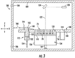
- AM system 100 generally defines a vertical direction V or Z-direction, a lateral direction L or X-direction, and a transverse direction T or Y-direction (see FIG. 1 ), each of which is mutually perpendicular, such that an orthogonal coordinate system is generally defined.
- system 100 includes a fixed enclosure or build area 102 which provides a contaminant-free and controlled environment for performing an additive manufacturing process.
- enclosure 102 serves to isolate and protect the other components of the system 100.
- enclosure 102 may be provided with a flow of an appropriate shielding gas, such as nitrogen, argon, or another suitable gas or gas mixture.
- enclosure 102 may define a gas inlet port 104 and a gas outlet port 106 for receiving a flow of gas to create a static pressurized volume or a dynamic flow of gas.
- Enclosure 102 may generally contain some or all components of AM system 100.
- AM system 100 generally includes a table 110, a powder supply 112, a scraper or recoater mechanism 114, an overflow container or reservoir 116, and a build platform 118 positioned within enclosure 102.
- an energy source 120 generates an energy beam 122 and a beam steering apparatus 124 directs energy beam 122 to facilitate the AM process as described in more detail below.
- a beam steering apparatus 124 directs energy beam 122 to facilitate the AM process as described in more detail below.
- table 110 is a rigid structure defining a planar build surface 130.
- planar build surface 130 defines a build opening 132 through which build chamber 134 may be accessed. More specifically, according to the illustrated embodiment, build chamber 134 is defined at least in part by vertical walls 136 and build platform 118.
- build surface 130 defines a supply opening 140 through which additive powder 142 may be supplied from powder supply 112 and a reservoir opening 144 through which excess additive powder 142 may pass into overflow reservoir 116. Collected additive powders may optionally be treated to sieve out loose, agglomerated particles before re-use.
- Powder supply 112 generally includes an additive powder supply container 150 which generally contains a volume of additive powder 142 sufficient for some or all of the additive manufacturing process for a specific part or parts.
- powder supply 112 includes a supply platform 152, which is a plate-like structure that is movable along the vertical direction within powder supply container 150. More specifically, a supply actuator 154 vertically supports supply platform 152 and selectively moves it up and down during the additive manufacturing process.
- AM system 100 further includes recoater mechanism 114, which is a rigid, laterally-elongated structure that lies proximate build surface 130.
- recoater mechanism 114 may be a hard scraper, a soft squeegee, or a roller.
- Recoater mechanism 114 is operably coupled to a recoater actuator 160 which is operable to selectively move recoater mechanism 114 along build surface 130.
- a platform actuator 164 is operably coupled to build platform 118 and is generally operable for moving build platform 118 along the vertical direction during the build process.
- actuators 154, 160, and 164 are illustrated as being hydraulic actuators, it should be appreciated that any other type and configuration of actuators may be used according to alternative embodiments, such as pneumatic actuators, hydraulic actuators, ball screw linear electric actuators, or any other suitable vertical support means. Other configurations are possible and within the scope of the present subject matter.
- energy source may be used to refer to any device or system of devices configured for directing an energy beam of suitable power and other operating characteristics towards a layer of additive powder to sinter, melt, or otherwise fuse a portion of that layer of additive powder during the build process.
- energy source 120 may be a laser or any other suitable irradiation emission directing device or irradiation device.
- an irradiation or laser source may originate photons or laser beam irradiation which is directed by the irradiation emission directing device or beam steering apparatus.
- beam steering apparatus 124 includes one or more mirrors, prisms, lenses, and/or electromagnets operably coupled with suitable actuators and arranged to direct and focus energy beam 122.
- beam steering apparatus 124 may be a galvanometer scanner that moves or scans the focal point of the laser beam 122 emitted by energy source 120 across the build surface 130 during the laser melting and sintering processes.
- energy beam 122 can be focused to a desired spot size and steered to a desired position in plane coincident with build surface 130.
- the galvanometer scanner in powder bed fusion technologies is typically of a fixed position but the movable mirrors/lenses contained therein allow various properties of the laser beam to be controlled and adjusted.
- beam steering apparatus may further include one or more of the following: optical lenses, deflectors, mirrors, beam splitters, telecentric lenses, etc.
- energy sources 120 may be used which may use an alternative beam steering apparatus 124.
- an electron beam gun or other electron source may be used to originate a beam of electrons (e.g., an "e-beam").
- the e-beam may be directed by any suitable irradiation emission directing device preferably in a vacuum.
- the irradiation emission directing device may be, for example, an electronic control unit which may include, for example, deflector coils, focusing coils, or similar elements.
- energy source 120 may include one or more of a laser, an electron beam, a plasma arc, an electric arc, etc.
- recoater actuator 160 may be lowered to provide a supply of powder 142 of a desired composition (for example, metallic, ceramic, and/or organic powder) into supply container 150.
- platform actuator 164 may move build platform 118 to an initial high position, e.g., such that it substantially flush or coplanar with build surface 130.
- Build platform 118 is then lowered below build surface 130 by a selected layer increment.
- the layer increment affects the speed of the additive manufacturing process and the resolution of a components or parts (e.g., blades 70) being manufactured.
- the layer increment may be about 10 to 100 micrometers (0.0004 to 0.004 in.).
- Additive powder is then deposited over the build platform 118 before being fused by energy source 120.
- supply actuator 154 may raise supply platform 152 to push powder through supply opening 140, exposing it above build surface 130.
- Recoater mechanism 114 may then be moved across build surface 130 by recoater actuator 160 to spread the raised additive powder 142 horizontally over build platform 118 (e.g., at the selected layer increment or thickness). Any excess additive powder 142 drops through the reservoir opening 144 into the overflow reservoir 116 as recoater mechanism 114 passes from left to right (as shown in FIG. 3 ). Subsequently, recoater mechanism 114 may be moved back to a starting position.
- recoater mechanism 114, recoater actuator 160, supply platform 152, and supply actuator 154 may generally operate to successively deposit layers of additive powder 142 or other additive material to facilitate the print process.
- these components may collectively be referred to herein as powder dispensing apparatus, system, or assembly.
- the leveled additive powder 142 may be referred to as a "build layer” 172 (see FIG. 4 ) and the exposed upper surface thereof may be referred to as build surface 130.
- build platform 118 is lowered into build chamber 134 during a build process, build chamber 134 and build platform 118 collectively surround and support a mass of additive powder 142 along with any components (e.g., blades 70) being built.
- This mass of powder is generally referred to as a "powder bed,” and this specific category of additive manufacturing process may be referred to as a "powder bed process.”
- the directed energy source 120 is used to melt a two-dimensional cross-section or layer of the component (e.g., blades 70) being built. More specifically, energy beam 122 is emitted from energy source 120 and beam steering apparatus 124 is used to steer the focal point 174 of energy beam 122 over the exposed powder surface in an appropriate pattern (referred to herein as a "toolpath"). A small portion of exposed layer of the additive powder 142 surrounding focal point 174, referred to herein as a "weld pool” or “melt pool” or “heat effected zone” 176 (best seen in FIG. 4 ) is heated by energy beam 122 to a temperature allowing it to sinter or melt, flow, and consolidate. As an example, melt pool 176 may be on the order of 100 micrometers (0.004 in.) wide. This step may be referred to as fusing additive powder 142.
- Build platform 118 is moved vertically downward by the layer increment, and another layer of additive powder 142 is applied in a similar thickness.
- the directed energy source 120 again emits energy beam 122 and beam steering apparatus 124 is used to steer the focal point 174 of energy beam 122 over the exposed powder surface in an appropriate pattern.
- the exposed layer of additive powder 142 is heated by energy beam 122 to a temperature allowing it to sinter or melt, flow, and consolidate both within the top layer and with the lower, previously-solidified layer.
- This cycle of moving build platform 118, applying additive powder 142, and then directed energy beam 122 to melt additive powder 142 is repeated until the entire component (e.g., blades 70) is complete.
- tooling assembly 200 may replace tooling assembly 52 as described in relation to FIG. 1 . Due to the similarity between tooling assembly 200, tooling assembly 52, and the AM system 100 in which they are configured for operating, like reference numerals will be used in FIGS. 5 through 10 to refer to like features described with respect to FIG. 1 .
- tooling assembly 200 will be described according to an exemplary embodiment of the present subject matter.
- tooling assembly 200 is generally configured for receiving one or more components, e.g., shown here as blades 70, and securely mounting such components for a subsequent additive manufacturing process.
- tooling assembly 200 may secure each of the plurality of blades 70 in a desired position and orientation relative to AM machine 100.
- Tooling assembly 200 generally includes a component fixture 202 configured for receiving one or more blades 70.
- each component fixture 202 is configured for receiving a single blade 70.
- blade 70 may define a dovetail 204 which is configured for receipt in a complementary slot 206 defined in component fixture 202.
- Component fixture 202 may generally be a rectangular block with a flat bottom surface 208 which may sit flush against another flat surface.
- Tooling assembly 200 may further include a mounting plate 210 that is configured for receiving the plurality of component fixtures 202.
- mounting plate 210 may be a rigid plate having a flat receiving surface 212 upon which component fixtures 202 may be seated.
- the "position" of a blade 70 may refer to the coordinates of a centroid of blade 70 in the X-Y plane.
- the "orientation" of a blade 70 may refer to an angular position of blade 70 about the Z-direction.
- each blade 70 may define a chord line 214 which is a straight line extending from a leading edge to a trailing edge of the airfoil (see FIG. 7 ).
- the orientation of each blade 70 may be defined according to the angular position of chord line 214. In this regard, for example, two blades 70 are said to have the same "orientation" when chord lines 214 of those blades 70 are parallel to each other.
- the exemplary repaired components described herein are blades 70, it should be appreciated that other components such as other airfoils or any other machine component may be repaired according to alternative embodiments, and the orientation of such components may be redefined accordingly.
- mounting plate 210 is configured for receiving a plurality of component fixtures 202 before being positioned at a known location on build platform 118.
- build platform 118 may be used directly as a mounting plate 210.
- mounting plate 210 may be removed altogether and component fixtures 202 may be positioned, oriented, and secured where desired directly on build platform 118.
- Component fixture 202 may generally be formed from any suitable material and may have any suitable shape. According to the illustrated embodiment component fixture 202 is formed from metal such that it may be reused for multiple repair and rebuild processes. Specifically, once blades 70 have been repaired using a powder bed additive manufacturing process as described below, each blade 70 may be removed from the corresponding component fixture 202 and component fixture 202 may be used to hold another blade 70 in a subsequent repair process.
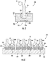
- Tooling assembly 200 may further include a magnet assembly 220 which is used to operably couple each component fixture 202 to mounting plate 210. More specifically, according to the illustrated embodiment, magnet assembly 220 both secures each component fixture 202 and positions each component fixture in the desired orientation for a specific print process. Generally speaking, magnet assembly 220 may include any suitable combination of permanent magnets, electromagnets, or other suitable magnetic materials or combinations thereof which are configured for operably coupling component fixtures 202 or blades 70 to mounting plate 210 as described herein. Several exemplary magnet assemblies 220 are described below to facilitate discussion of operating principles of the present disclosure, but are not intended to limit the scope of the present disclosure in any manner.
- magnet assembly 220 includes a fixture magnet 222 that is mounted to each component fixture 202.
- tooling assembly 200 may include a plurality of plate magnets 224 that are mounted to mounting plate 210 at the desired positions where blades 70 should be secured.
- Fixture magnet 222 and plate magnet 224 may be mounted or secured to component fixture 202 and mounting plate 210, respectively, in any suitable manner.
- component fixture 202 and mounting plate 210 may each define one or more magnet recesses 226 which are configured to receive respective magnets 222, 224.
- fixture magnet 222 may be positioned within magnet recess 226 defined in flat bottom surface 208 of component fixture 202.
- Magnets 222, 224 may be secured within magnet recesses 226 using an adhesive, a mechanical fastener, a press fit interface, or in any other suitable manner. According to alternative embodiments, fixture magnet 222 may be embedded within component fixture 202 and plate magnets 224 may be embedded within mounting plate 210.
- fixture magnet 222 and plate magnet 224 may have opposing magnetic poles such that component fixtures 202 are urged toward mounting plate 210.
- each fixture magnet 222 may be a south pole of a permanent magnet.
- each plate magnet 224 may be a north pole of a permanent magnet.
- fixture magnet 222 and plate magnet 224 each generate magnetic fields which result in a magnetic attraction that urges component fixture 202 toward mounting plate 210.
- fixture magnet 222 and plate magnet 224 may swap positions, may generate magnetic fields having any other suitable direction and magnitude, and may be any other suitable type of device for generating a magnetic field.
- a plurality of blades 70 may be mounted at a fixed position on mounting plate 210 by positioning the corresponding component fixture 202 near mounting plate 210 such that plate magnet 224 attracts fixture magnet 222 to position and secure component fixture 202. After all blades 70 have been mounted to mounting plate 210, the material removal process may be performed to remove material above repair surface 72 of each blade 70. By contrast, according to alternative embodiments, each blade 70 may be separately prepared by grinding or removing the tip of that blade 70 prior to mounting on mounting plate 210.
- fixture magnet 222 and plate magnet 224 may have a non-circular geometry such that the magnetic field generated by fixture magnet 222 and plate magnet 224 have a tendency to orient component fixture 202 and thus blades 70 along a certain direction.
- the intensity of the magnetic field at a sharp corner or other protrusion 230 may be stronger than along the rounded surfaces of magnets 222, 224.
- magnets 222, 224 have a tendency to align such that sharp corners or protrusions 230 point towards the same direction and such that magnets 222, 224 have the same alignment within the X-Y plane. It should be appreciated that any suitable unbalanced geometry of magnets 222, 224 may be used to generate magnetic fields which have a tendency to align with each other. Although an exemplary geometry is described herein, the present subject matter is not intended to be limited to such a geometry.
- magnet assembly 200 may include a plurality of magnets positioned in each of component fixtures 202 and mounting plate 210 in order to position component fixtures 202 at the desired positions and orient blades 70 along the desired direction.
- magnet assembly 220 may include a first fixture magnet 240 and a second fixture magnet 242 mounted to each component fixture 202. More specifically, first fixture magnet 240 and second fixture magnet 242 may be spaced apart along a fixture magnetic axis 244 and may have opposing magnetic poles (e.g., north and south poles).
- each blade position 248 defined on mounting plate 210 may include a first plate magnet 250 and a second plate magnet 252 mounted to mounting plate 210.
- first plate magnet 250 and second plate magnet 252 may be spaced apart along a plate magnetic axis 254 and may have opposing magnetic poles (e.g., north and south poles).
- positioning component fixture 202 close to blade position 248 on mounting plate 210 will urge component fixture 202 toward mounting plate 210 such that fixture magnetic axis 244 is substantially parallel to plate magnetic axis 254.
- each component fixture 202 is secured to mounting plate 210 at the desired position and in the desired orientation.
- component fixture 202 and mounting plate 210 are illustrated herein as including separate magnets having opposite magnetic poles, it should be appreciated that a single bar magnet or any other magnetic coupling assembly may be used according to alternative embodiments.
- magnet assembly 220 could instead include an electromagnet assembly 260 which is configured for securing component fixtures 202 to mounting plate 210 when energized with electrical current.
- an electromagnet 262 is intended to refer to a type of magnet in which the magnetic field is produced by an electric current.
- electromagnets 262 usually consist of wire wound into a coil which is electrically coupled to a power supply 264. Power supply 264 selectively provides a current through the wire of electromagnet 262 which creates a magnetic field.
- an exemplary electromagnet 262 is described, it should be appreciated that any other suitable type or configuration of electromagnet may be used according to alternative embodiments.
- component fixture 202 may include an embedded magnet or may be formed from a magnetic material, such that electromagnet 262 attracts component fixture 202 when energized.
- electromagnet 262 attracts component fixtures 202 toward mounting plate 210, but may not facilitate appropriate alignment or orientation of such component fixtures 202.
- mounting plate 210 may define a plurality of recesses 266 which may be configured for receiving component fixtures 202 and preventing rotation thereof. In this manner, a plurality of blades 70 may be positioned in the desired alignment on mounting plate 210 by positioning component fixtures 202 on mounting plate within recesses 266 and energizing electromagnet 262 using power supply 264.
- electromagnet 262 may be deenergized for easy removal of component fixtures 202.
- Method 300 can be used to repair blades 70 using additive repair system 50, AM machine 100, and tooling assembly 200, or to repair any other suitable component using any other suitable additive manufacturing machine or system.
- controller 60 may be configured for implementing some or all steps of method 300.
- the exemplary method 300 is discussed herein only to describe exemplary aspects of the present subject matter, and is not intended to be limiting.
- method 300 includes, at step 310, mounting a component in a component fixture.
- a plurality of blades 70 which need to be repaired may be positioned in corresponding component fixtures 202, e.g., by sliding dovetails 204 of each blade 70 in a complementary slot 206 of each component fixture 202.
- Step 320 includes positioning the component fixture on a mounting plate.
- the mounting plate 210 may be a flat plate configured for receipt on build platform 118 of AM machine 100.
- mounting plate 210 could instead replace build platform 118.
- Component fixtures 202 may be positioned directly on mounting plate 210.
- Step 330 includes securing the component in the desired orientation on the mounting plate using a magnet assembly.
- the magnet assembly 200 may include a fixture magnet 222 and plate magnet 224 which have opposing polarities and are positioned within component fixture 202 and mounting plate 210, or vice versa, such that component fixture 202 is urged toward mounting plate and secured thereto.
- component fixture 202 and mounting plate 210 may each include bar magnets having opposing poles or may each include two separate magnets to create corresponding magnetic fields defining magnetic axes that can be aligned to orient component fixture 202 as desired.
- component fixtures 202 may be secured using electromagnet assembly 260 or any other suitable device for generating a magnetic field or attractive forces between component fixture 202 and mounting plate 210.
- Step 340 may include removing material above a repair surface of the component using a material removal assembly while the component is positioned in the component fixture.
- material removal assembly 54 may be operated to remove the tip of each blade 70 down to repair surface 72.
- each blade 70 may be prepared, e.g., by grinding, prior to mounting in component fixture 202 and/or on to mounting plate 210.
- method 300 may further include additively printing repair segments onto repair surface 72 of each blade 70 using AM machine 100.
- step 350 includes depositing a layer of additive powder over repair surface of the component using a powder dispensing assembly and step 360 includes selectively irradiating the layer of additive powder to fuse the layer of additive powder onto the repair surface of the component.
- an energy source may fuse additive powder onto each blade tip layer by layer until the component is repaired to an original CAD model or to another suitable geometry.
- FIG. 11 depicts an exemplary control method having steps performed in a particular order for purposes of illustration and discussion.
- steps of any of the methods discussed herein can be adapted, rearranged, expanded, omitted, or modified in various ways without deviating from the scope of the present disclosure.
- aspects of the methods are explained using additive repair system 50, AM machine 100, and tooling assembly 200 as an example, it should be appreciated that these methods may be applied to repairing or rebuilding any other number, type, and configuration of components using any suitable tooling fixture or additive manufacturing machine or system.
Landscapes
- Engineering & Computer Science (AREA)
- Chemical & Material Sciences (AREA)
- Materials Engineering (AREA)
- Manufacturing & Machinery (AREA)
- Mechanical Engineering (AREA)
- Physics & Mathematics (AREA)
- Optics & Photonics (AREA)
- Plasma & Fusion (AREA)
- Composite Materials (AREA)
- General Engineering & Computer Science (AREA)
- Ceramic Engineering (AREA)
- Powder Metallurgy (AREA)
Abstract
Description
- The present subject matter relates generally to additive manufacturing machines, and more particularly to tooling assemblies for aligning a plurality of components in a desired orientation for a powder bed additive manufacturing process.
- Machine or device components frequently experience damage, wear, and/or degradation throughout their service life. For example, serviced compressor blades of a gas turbine engine show erosion, defects, and/or cracks after long term use. Specifically, for example, such blades are subject to significant stresses which inevitably cause blades to wear over time, particularly near the tip of the blade. For example, blade tips are susceptible to wear or damage from friction or rubbing between the blade tips and shrouds, from chemical degradation or oxidation from hot gasses, from fatigue caused by cyclic loading and unloading, from diffusion creep of crystalline lattices, etc.
- Notably, worn or damaged blades may result in machine failure or performance degradation if not corrected. Specifically, such blades may cause a turbomachine to exhibit reduced operating efficiency as gaps between blade tips and turbine shrouds may allow gasses to leak through the turbine stages without being converted to mechanical energy. When efficiency drops below specified levels, the turbomachine is typically removed from service for overhaul and refurbishment. Moreover, weakened blades may result in complete fractures and catastrophic failure of the engine.
- As a result, compressor blades for a gas turbine engine are typically the target of frequent inspections, repairs, or replacements. It is frequently very expensive to replace such blades altogether, however, some can be repaired for extended lifetime at relatively low cost (as compared to replacement with entirely new blades). Nevertheless, existing repair processes tend to be labor intensive and time consuming.
- For example, a traditional compressor blade tip repair process uses a welding/cladding technique where repair materials are supplied, in either powder or wire form, to the blade tips. The repair materials are melted by focused power source (e.g., laser, e-beam, plasma arc, etc.) and bonded to blade tips. However, blades repaired with such welding/cladding technique need tedious post-processing to achieve the target geometry and surface finish. Specifically, due to the bulky feature size of the welding/cladding repair joint, the repaired blades require heavy machining to remove the extra materials on the tip, and further require a secondary polishing process to achieve a target surface finish. Notably, such a process is performed on a single blade at a time, is very labor intensive and tedious, and results in very large overall labor costs for a single repair.
- Alternatively, other direct-energy-deposition (DED) methods may be used for blade repair, e.g., such as cold spray, which directs high-speed metal powders to bombard the target or base component such that the powders deform and deposit on the base component. However, none of these DED methods are suitable for batch processing or for repairing a large number of components in a time efficient manner, thus providing little or no business value.
- Accordingly, novel systems and methods have been developed and are presented herein for repairing or rebuilding worn compressor blades (or any other components) using a powder bed additive manufacturing process. Specifically, such a repair process generally includes removing the worn portion of each of a plurality of compressor blades, positioning the plurality of compressor blades on a build platform of an additive manufacturing machine, determining the precise location of each blade tip, and printing repair segments directly onto the blade tips, layer by layer, until the compressor blades reach their original dimensions or another suitable target size and shape.
- Notably, it may be desirable that each of the plurality of components is mounted on the build platform at a known and fixed spacing and orientation. In this regard, a vision system which is used to determine the precise coordinates of each blade tip may more accurately find such tips if all blades are equally spaced and oriented in the same direction. For example, to facilitate the vision system imaging process, the parts are preferably secured at same locations with high repeatability. Similarly, the recoating and print process may be improved if the blades are uniformly spaced and the recoater passes over each blade tip along the same direction.
- Accordingly, a system and method for precisely and repeatedly mounting serviced components in an additive manufacturing machine would be useful. More particularly, an additive manufacturing machine including a tooling assembly for quickly and effectively mounting a plurality of compressor blades with equal spacing and uniform orientation would be particularly beneficial.
- Aspects and advantages of the invention will be set forth in part in the following description, or may be obvious from the description, or may be learned through practice of the invention.
- In one exemplary embodiment of the present disclosure, a tooling assembly for mounting a component in a powder bed additive manufacturing machine is provided. The tooling assembly comprising includes a component fixture configured for receiving the component, a mounting plate configured for receiving the component fixture, and a magnet assembly operably coupling the mounting plate to the component fixture for securing the component fixture to the mounting plate in a desired orientation.
- In another exemplary aspect of the present disclosure, a method of mounting a component in a powder bed additive manufacturing machine is provided. The method includes mounting the component in a component fixture, positioning the component fixture on a mounting plate, and securing the component in the desired orientation on the mounting plate using a magnet assembly.
- These and other features, aspects, and advantages of the present invention will become better understood with reference to the following description and appended claims. The accompanying drawings, which are incorporated in and constitute a part of this specification, illustrate embodiments of the invention and, together with the description, serve to explain the principles of the invention.
- A full and enabling disclosure of the present invention, including the best mode thereof, directed to one of ordinary skill in the art, is set forth in the specification, which makes reference to the appended figures.
-
FIG. 1 shows a schematic representation of an additive repair system that may be used for repairing or rebuilding components according to an exemplary embodiment of the present subject matter. -
FIG. 2 depicts certain components of a controller according to example embodiments of the present subject matter. -
FIG. 3 shows a schematic view of an additive manufacturing machine that may be used as part of the exemplary additive manufacturing system ofFIG. 1 according to an exemplary embodiment of the present subject matter. -
FIG. 4 shows a close-up schematic view of a build platform of the exemplary additive manufacturing machine ofFIG. 3 according to an exemplary embodiment of the present subject matter. -
FIG. 5 is a schematic cross sectional view of part of a magnet assembly mounted within a component fixture according to an exemplary embodiment of the present subject matter. -
FIG. 6 is a schematic cross sectional view of a plurality of component fixtures mounted to a mounting plate using magnet assemblies in accordance with an exemplary embodiment of the present subject matter. -
FIG. 7 provides a schematic view of another magnet assembly according to an exemplary embodiment of the present subject matter. -
FIG. 8 is a schematic cross sectional view of part of a magnet assembly mounted within a component fixture according to an exemplary embodiment of the present subject matter. -
FIG. 9 is a schematic view of the exemplary component fixture ofFIG. 8 being mounted to a mounting plate using the exemplary magnet assembly ofFIG. 8 . -
FIG. 10 provides a schematic view of another magnet assembly according to an exemplary embodiment of the present subject matter. -
FIG. 11 is a method of mounting a plurality of components in a powder bed additive manufacturing machine according to an exemplary embodiment of the present subject matter. - Repeat use of reference characters in the present specification and drawings is intended to represent the same or analogous features or elements of the present invention.
- Reference now will be made in detail to embodiments of the invention, one or more examples of which are illustrated in the accompanying drawings. Each example is provided by way of explanation of the invention, not limitation of the invention. In fact, it will be apparent to those skilled in the art that various configurations, modifications, and variations can be made in the present invention without departing from the scope or spirit of the invention. For instance, features illustrated or described as part of one embodiment can be used with another embodiment to yield a still further embodiment. Thus, it is intended that the present invention covers such modifications and variations as come within the scope of the appended claims and their equivalents.
- As used herein, the terms "first," "second," and "third" may be used interchangeably to distinguish one component from another and are not intended to signify location or importance of the individual components. In addition, the terms "upstream" and "downstream" refer to the relative direction with respect to the motion of an object or a flow of fluid. For example, "upstream" refers to the direction from which the object has moved or fluid has flowed, and "downstream" refers to the direction to which the object is moving or the fluid is flowing. Furthermore, as used herein, terms of approximation, such as "approximately," "substantially," or "about," refer to being within a ten percent margin of error.
- Aspects of the present subject matter are directed to a system and method for repairing one or more components using an additive manufacturing process. The method includes securing the components in a tooling assembly such that a repair surface of each component is positioned within a single build plane, determining a repair toolpath corresponding to the repair surface of each component using a vision system, depositing a layer of additive powder over the repair surface of each component using a powder dispensing assembly, and selectively irradiating the layer of additive powder along the repair toolpath to fuse the layer of additive powder onto the repair surface of each component.
- Specifically, aspects of the present subject matter provide a tooling assembly for mounting a plurality of components, such as compressor blades, in a powder bed additive manufacturing machine to facilitate such a repair process. The tooling assembly includes component fixtures configured for receiving each of the compressor blades, a mounting plate for receiving the component fixtures, and a magnet assembly operably coupling the component fixtures to the mounting plate in a desired position and orientation to facilitate an improved printing process.
- As described in detail below, exemplary embodiments of the present subject matter involve the use of additive manufacturing machines or methods. As used herein, the terms "additively manufactured" or "additive manufacturing techniques or processes" refer generally to manufacturing processes wherein successive layers of material(s) are provided on each other to "build-up," layer-by-layer, a three-dimensional component. The successive layers generally fuse together to form a monolithic component which may have a variety of integral subcomponents.
- Although additive manufacturing technology is described herein as enabling fabrication of complex objects by building objects point-by-point, layer-by-layer, typically in a vertical direction, other methods of fabrication are possible and within the scope of the present subject matter. For example, although the discussion herein refers to the addition of material to form successive layers, one skilled in the art will appreciate that the methods and structures disclosed herein may be practiced with any additive manufacturing technique or manufacturing technology. For example, embodiments of the present invention may use layer-additive processes, layer-subtractive processes, or hybrid processes.
- Suitable additive manufacturing techniques in accordance with the present disclosure include, for example, Fused Deposition Modeling (FDM), Selective Laser Sintering (SLS), 3D printing such as by inkjets and laserjets, Sterolithography (SLA), Direct Selective Laser Sintering (DSLS), Electron Beam Sintering (EBS), Electron Beam Melting (EBM), Laser Engineered Net Shaping (LENS), Laser Net Shape Manufacturing (LNSM), Direct Metal Deposition (DMD), Digital Light Processing (DLP), Direct Selective Laser Melting (DSLM), Selective Laser Melting (SLM), Direct Metal Laser Melting (DMLM), and other known processes.
- In addition to using a direct metal laser sintering (DMLS) or direct metal laser melting (DMLM) process where an energy source is used to selectively sinter or melt portions of a layer of powder, it should be appreciated that according to alternative embodiments, the additive manufacturing process may be a "binder jetting" process. In this regard, binder jetting involves successively depositing layers of additive powder in a similar manner as described above. However, instead of using an energy source to generate an energy beam to selectively melt or fuse the additive powders, binder jetting involves selectively depositing a liquid binding agent onto each layer of powder. The liquid binding agent may be, for example, a photo-curable polymer or another liquid bonding agent. Other suitable additive manufacturing methods and variants are intended to be within the scope of the present subject matter.
- The additive manufacturing processes described herein may be used for forming components using any suitable material. For example, the material may be plastic, metal, concrete, ceramic, polymer, epoxy, photopolymer resin, or any other suitable material that may be in solid, liquid, powder, sheet material, wire, or any other suitable form. More specifically, according to exemplary embodiments of the present subject matter, the additively manufactured components described herein may be formed in part, in whole, or in some combination of materials including but not limited to pure metals, nickel alloys, chrome alloys, titanium, titanium alloys, magnesium, magnesium alloys, aluminum, aluminum alloys, iron, iron alloys, stainless steel, and nickel or cobalt based superalloys (e.g., those available under the name Inconel® available from Special Metals Corporation). These materials are examples of materials suitable for use in the additive manufacturing processes described herein, and may be generally referred to as "additive materials."
- In addition, one skilled in the art will appreciate that a variety of materials and methods for bonding those materials may be used and are contemplated as within the scope of the present disclosure. As used herein, references to "fusing" may refer to any suitable process for creating a bonded layer of any of the above materials. For example, if an object is made from polymer, fusing may refer to creating a thermoset bond between polymer materials. If the object is epoxy, the bond may be formed by a crosslinking process. If the material is ceramic, the bond may be formed by a sintering process. If the material is powdered metal, the bond may be formed by a melting or sintering process. One skilled in the art will appreciate that other methods of fusing materials to make a component by additive manufacturing are possible, and the presently disclosed subject matter may be practiced with those methods.
- In addition, the additive manufacturing process disclosed herein allows a single component to be formed from multiple materials. Thus, the components described herein may be formed from any suitable mixtures of the above materials. For example, a component may include multiple layers, segments, or parts that are formed using different materials, processes, and/or on different additive manufacturing machines. In this manner, components may be constructed which have different materials and material properties for meeting the demands of any particular application. In addition, although the components described herein are constructed entirely by additive manufacturing processes, it should be appreciated that in alternate embodiments, all or a portion of these components may be formed via casting, machining, and/or any other suitable manufacturing process. Indeed, any suitable combination of materials and manufacturing methods may be used to form these components.
- An exemplary additive manufacturing process will now be described. Additive manufacturing processes fabricate components using three-dimensional (3D) information, for example a three-dimensional computer model, of the component. Accordingly, a three-dimensional design model of the component may be defined prior to manufacturing. In this regard, a model or prototype of the component may be scanned to determine the three-dimensional information of the component. As another example, a model of the component may be constructed using a suitable computer aided design (CAD) program to define the three-dimensional design model of the component.
- The design model may include 3D numeric coordinates of the entire configuration of the component including both external and internal surfaces of the component. For example, the design model may define the body, the surface, and/or internal passageways such as openings, support structures, etc. In one exemplary embodiment, the three-dimensional design model is converted into a plurality of slices or segments, e.g., along a central (e.g., vertical) axis of the component or any other suitable axis. Each slice may define a thin cross section of the component for a predetermined height of the slice. The plurality of successive cross-sectional slices together form the 3D component. The component is then "built-up" slice-by-slice, or layer-by-layer, until finished.
- In this manner, the components described herein may be fabricated using the additive process, or more specifically each layer is successively formed, e.g., by fusing or polymerizing a plastic using laser energy or heat or by sintering or melting metal powder. For example, a particular type of additive manufacturing process may use an energy beam, for example, an electron beam or electromagnetic radiation such as a laser beam, to sinter or melt a powder material. Any suitable laser and laser parameters may be used, including considerations with respect to power, laser beam spot size, and scanning velocity. The build material may be formed by any suitable powder or material selected for enhanced strength, durability, and useful life, particularly at high temperatures.
- Each successive layer may be, for example, between about 10 µm and 200 µm, although the thickness may be selected based on any number of parameters and may be any suitable size according to alternative embodiments. Therefore, utilizing the additive formation methods described above, the components described herein may have cross sections as thin as one thickness of an associated powder layer, e.g., 10 µm, utilized during the additive formation process.
- In addition, utilizing an additive process, the surface finish and features of the components may vary as need depending on the application. For example, the surface finish may be adjusted (e.g., made smoother or rougher) by selecting appropriate laser scan parameters (e.g., laser power, scan speed, laser focal spot size, etc.) during the additive process, especially in the periphery of a cross-sectional layer which corresponds to the part surface. For example, a rougher finish may be achieved by increasing laser scan speed or decreasing the size of the melt pool formed, and a smoother finish may be achieved by decreasing laser scan speed or increasing the size of the melt pool formed. The scanning pattern and/or laser power can also be changed to change the surface finish in a selected area.
- After fabrication of the component is complete, various post-processing procedures may be applied to the component. For example, post processing procedures may include removal of excess powder by, for example, blowing or vacuuming. Other post processing procedures may include a stress relief process. Additionally, thermal, mechanical, and/or chemical post processing procedures can be used to finish the part to achieve a desired strength, surface finish, and other component properties or features.
- Notably, in exemplary embodiments, several aspects and features of the present subject matter were previously not possible due to manufacturing restraints. However, the present inventors have advantageously utilized current advances in additive manufacturing techniques to improve various components and the method of additively manufacturing such components. While the present disclosure is not limited to the use of additive manufacturing to form these components generally, additive manufacturing does provide a variety of manufacturing advantages, including ease of manufacturing, reduced cost, greater accuracy, etc.
- Also, the additive manufacturing methods described above enable much more complex and intricate shapes and contours of the components described herein to be formed with a very high level of precision. For example, such components may include thin additively manufactured layers, cross sectional features, and component contours. In addition, the additive manufacturing process enables the manufacture of a single component having different materials such that different portions of the component may exhibit different performance characteristics. The successive, additive nature of the manufacturing process enables the construction of these novel features. As a result, components formed using the methods described herein may exhibit improved performance and reliability.
- Referring now to
FIG. 1 , an exemplaryadditive repair system 50 will be described according to an exemplary embodiment of the present subject matter. As illustrated,additive repair system 50 generally includes a tooling fixture orassembly 52, amaterial removal assembly 54, avision system 56, auser interface panel 58, and an additive manufacturing machine orsystem 100. Furthermore, asystem controller 60 may be operably coupled with some or all parts ofadditive repair system 50 for facilitating system operation. For example,system controller 60 may be operably coupled touser interface panel 58 to permit operator communication withadditive repair system 50, e.g., to input commands, upload printing toolpaths or CAD models, initiating operating cycles, etc.Controller 60 may further be in communication withvision system 56 for receiving imaging data and withAM machine 100 for performing a printing process. - According to exemplary embodiments, tooling
assembly 52 is generally configured for supporting a plurality of components in a desired position and orientation. According to exemplary embodiments, toolingassembly 52 supports 20 highpressure compressor blades 70 during an additive manufacturing repair process. Specifically, the additive manufacturing process may be a powder bed fusion process (e.g., a DMLM or DMLS process as described above). Although the repaired components are illustrated herein ascompressor blades 70 of a gas turbine engine, it should be appreciated that any other suitable component may be repaired, such as turbine blades, other airfoils, or components from other machines. In order to achieve proper recoating and to facilitate the printing process, it may be desirable to position allblades 70 in the same orientation and at the same height such that arepair surface 72 of each blade is in a single build plane.Tooling assembly 52 is a fixture intended to secureblades 70 in such desired position and orientation. -
Material removal assembly 54 may include a machine or device configured for grinding, machining, brushing, etching, polishing, wire electrical discharge machining (EDM), cutting, or otherwise substantively modifying a component, e.g., by subtractive modification or material removal. For example,material removal assembly 54 may include a belt grinder, a disc grinder, or any other grinding or abrasive mechanism. According to an exemplary embodiment,material removal assembly 54 may be configured for removing material from a tip of eachblade 70 to obtain adesirable repair surface 72. For example, as explained briefly above,material removal assembly 54 may remove at least a portion ofblades 70 that have been worn or damaged, e.g., which may include microcracks, pits, abrasions, defects, foreign material, depositions, imperfections, and the like. According to an exemplary embodiment, eachblade 70 is prepared usingmaterial removal assembly 54 to achieve the desiredrepair surface 72, after which theblades 70 are all mounted intooling assembly 52 and leveled appropriately. However, according to alternative embodiments,material removal assembly 54 may grind eachblade 70 as it is fixed in position intooling assembly 52. - After the blades are prepared,
vision system 56 may be used to obtain an image or digital representation of the precise position and coordinates of eachblade 70 positioned intooling assembly 52. In this regard, according to exemplary embodiments,vision system 56 may include any suitable camera orcameras 80, scanners, imaging devices, or other machine vision device that may be operably configured to obtain image data that includes a digital representation of one or more fields of view. Such a digital representation may sometimes be referred to as a digital image or an image; however, it will be appreciated that the present disclosure may be practiced without rendering such a digital representation in human-visible form. Nevertheless, in some embodiments, a human-visible image corresponding to a field of view may be displayed on theuser interface 58 based at least in part on such a digital representation of one or more fields of view. -
Vision system 56 allows theadditive repair system 50 to obtain information pertaining to one ormore blades 70 onto which one or more repair segments 74 (seeFIG. 4 ) may be respectively additively printed. In particular, thevision system 56 allows the one ormore blades 70 to be located and defined so that theadditive manufacturing machine 100 may be instructed to print one ormore repair segments 74 on a corresponding one ormore blades 70 with suitably high accuracy and precision. According to an exemplary embodiment, the one ormore blades 70 may be secured totooling assembly 52, a mounting plate, a build platform, or any other fixture withrepair surface 72 of therespective blades 70 aligned to asingle build plane 82. - The one or
more cameras 80 of thevision system 56 may be configured to obtain two-dimensional or three-dimensional image data, including a two-dimensional digital representation of a field of view and/or a three-dimensional digital representation of a field of view. Alignment of therepair surface 72 of theblades 70 with thebuild plane 82 allows the one ormore cameras 80 to obtain higher quality images. For example, the one ormore cameras 80 may have a focal length adjusted or adjustable to thebuild plane 82. With therepair surface 72 of one ormore blades 70 aligned to thebuild plane 82, the one or more cameras may readily obtain digital images of therepair surface 72. The one ormore cameras 80 may include a field of view that encompasses all or a portion of the one ormore blades 70 secured to thetooling assembly 52. For example, a single field of view may be wide enough to encompass a plurality ofblades 70, such as each of a plurality of workpieces secured totooling assembly 52. Alternatively, a field of view may more narrowly focus on anindividual blade 70 such that digital representations ofrespective blades 70 are obtained separately. It will be appreciated that separately obtained digital images may be stitched together to obtain a digital representation of a plurality of components orblades 70. In some embodiments, thecamera 80 may include a collimated lens configured to provide a flat focal plane, such thatblades 70 or portions thereof located towards the periphery of the field of view are not distorted. Additionally, or in the alternative, thevision system 56 may utilize a distortion correction algorithm to address any such distortion. - Image data obtained by the
vision system 56, including a digital representation of one ormore blades 70 may be transmitted to a control system, such ascontroller 60.Controller 60 may be configured to determine arepair surface 72 of each of a plurality ofblades 70 from one or more digital representations of one or more fields of view having been captured by thevision system 56, and then determine one or more coordinates of therepair surface 72 of respective ones of the plurality ofblades 70. Based on the one or more digital representations,controller 60 may generate one or more print commands (e.g., corresponding to one or more repair toolpaths, e.g., the path of a laser focal point), which may be transmitted to anadditive manufacturing machine 100 such that theadditive manufacturing machine 100 may additively print a plurality ofrepair segments 74 on respective ones of the plurality ofblades 70. The one or more print commands may be configured to additively print a plurality ofrepair segments 74 with each respective one of the plurality ofrepair segments 74 being located on therepair surface 72 of acorresponding blade 70. - Each of the components and subsystems of
additive repair system 50 are described herein in the context of an additive blade repair process. However, it should be appreciated that aspects of the present subject matter may be used to repair or rebuild any suitable components. The present subject matter is not intended to be limited to the specific repair process described. In addition,FIG. 1 illustrates each of the systems as being distinct or separate from each other and implies the process steps should be performed in a particular order, however, it should be appreciated that these subsystems may be integrated into a single machine, process steps may be swapped, and other changes to the build process may be implemented while remaining within the scope of the present subject matter. - For example,
vision system 56 andadditive manufacturing machine 100 may be provided as a single, integrated unit or as separate stand-alone units. In addition,controller 60 may include one or more control systems. For example, asingle controller 60 may be operably configured to control operations of thevision system 56 and theadditive manufacturing machine 100, orseparate controllers 60 may be operably configured to respectively control thevision system 56 and theadditive manufacturing machine 100. - Operation of
additive repair system 50,vision system 56, andAM machine 100 may be controlled by electromechanical switches or by a processing device or controller 60 (see, e.g.,FIGS. 1 through 2 ). According to exemplary embodiments,controller 60 may be operatively coupled touser interface panel 58 for user manipulation, e.g., to control the operation of various components ofAM machine 100 orsystem 50. In this regard,controller 60 may operably couple all systems and subsystems withinadditive repair system 50 to permit communication and data transfer therebetween. In this manner,controller 60 may be generally configured for operatingadditive repair system 50 or performing one or more of the methods described herein. -
FIG. 2 depicts certain components ofcontroller 60 according to example embodiments of the present disclosure.Controller 60 can include one or more computing device(s) 60A which may be used to implement methods as described herein. Computing device(s) 60A can include one or more processor(s) 60B and one or more memory device(s) 60C. The one or more processor(s) 60B can include any suitable processing device, such as a microprocessor, microcontroller, integrated circuit, an application specific integrated circuit (ASIC), a digital signal processor (DSP), a field-programmable gate array (FPGA), logic device, one or more central processing units (CPUs), graphics processing units (GPUs) (e.g., dedicated to efficiently rendering images), processing units performing other specialized calculations, etc. The memory device(s) 60C can include one or more non-transitory computer-readable storage medium(s), such as RAM, ROM, EEPROM, EPROM, flash memory devices, magnetic disks, etc., and/or combinations thereof. - The memory device(s) 60C can include one or more computer-readable media and can store information accessible by the one or more processor(s) 60B, including
instructions 60D that can be executed by the one or more processor(s) 60B. For instance, the memory device(s) 60C can storeinstructions 60D for running one or more software applications, displaying a user interface, receiving user input, processing user input, etc. In some implementations, theinstructions 60D can be executed by the one or more processor(s) 60B to cause the one or more processor(s) 60B to perform operations, e.g., such as one or more portions of methods described herein. Theinstructions 60D can be software written in any suitable programming language or can be implemented in hardware. Additionally, and/or alternatively, theinstructions 60D can be executed in logically and/or virtually separate threads on processor(s) 60B. - The one or more memory device(s) 60C can also store
data 60E that can be retrieved, manipulated, created, or stored by the one or more processor(s) 60B. Thedata 60E can include, for instance, data to facilitate performance of methods described herein. Thedata 60E can be stored in one or more database(s). The one or more database(s) can be connected tocontroller 60 by a high bandwidth LAN or WAN, or can also be connected to controller through one or more network(s) (not shown). The one or more database(s) can be split up so that they are located in multiple locales. In some implementations, thedata 60E can be received from another device. - The computing device(s) 60A can also include a communication module or
interface 60F used to communicate with one or more other component(s) ofcontroller 60 oradditive manufacturing machine 100 over the network(s). Thecommunication interface 60F can include any suitable components for interfacing with one or more network(s), including for example, transmitters, receivers, ports, controllers, antennas, or other suitable components. - Referring now to
FIG. 3 , an exemplary laser powder bed fusion system, such as a DMLS orDMLM system 100, will be described according to an exemplary embodiment. Specifically,AM system 100 is described herein as being used to build or repairblades 70. It should be appreciated thatblades 70 are only an exemplary component to be built or repaired and are used primarily to facilitate description of the operation ofAM machine 100. The present subject matter is not intended to be limited in this regard, but insteadAM machine 100 may be used for printing repair segments on any suitable plurality of components. - As illustrated,
AM system 100 generally defines a vertical direction V or Z-direction, a lateral direction L or X-direction, and a transverse direction T or Y-direction (seeFIG. 1 ), each of which is mutually perpendicular, such that an orthogonal coordinate system is generally defined. As illustrated,system 100 includes a fixed enclosure or buildarea 102 which provides a contaminant-free and controlled environment for performing an additive manufacturing process. In this regard, for example,enclosure 102 serves to isolate and protect the other components of thesystem 100. In addition,enclosure 102 may be provided with a flow of an appropriate shielding gas, such as nitrogen, argon, or another suitable gas or gas mixture. In this regard,enclosure 102 may define agas inlet port 104 and agas outlet port 106 for receiving a flow of gas to create a static pressurized volume or a dynamic flow of gas. -
Enclosure 102 may generally contain some or all components ofAM system 100. According to an exemplary embodiment,AM system 100 generally includes a table 110, apowder supply 112, a scraper orrecoater mechanism 114, an overflow container orreservoir 116, and abuild platform 118 positioned withinenclosure 102. In addition, anenergy source 120 generates anenergy beam 122 and abeam steering apparatus 124 directsenergy beam 122 to facilitate the AM process as described in more detail below. Each of these components will be described in more detail below. - According to the illustrated embodiment, table 110 is a rigid structure defining a
planar build surface 130. In addition,planar build surface 130 defines abuild opening 132 through whichbuild chamber 134 may be accessed. More specifically, according to the illustrated embodiment, buildchamber 134 is defined at least in part byvertical walls 136 and buildplatform 118. In addition,build surface 130 defines asupply opening 140 through whichadditive powder 142 may be supplied frompowder supply 112 and areservoir opening 144 through which excessadditive powder 142 may pass intooverflow reservoir 116. Collected additive powders may optionally be treated to sieve out loose, agglomerated particles before re-use. -
Powder supply 112 generally includes an additivepowder supply container 150 which generally contains a volume ofadditive powder 142 sufficient for some or all of the additive manufacturing process for a specific part or parts. In addition,powder supply 112 includes asupply platform 152, which is a plate-like structure that is movable along the vertical direction withinpowder supply container 150. More specifically, asupply actuator 154 vertically supportssupply platform 152 and selectively moves it up and down during the additive manufacturing process. -
AM system 100 further includesrecoater mechanism 114, which is a rigid, laterally-elongated structure that liesproximate build surface 130. For example,recoater mechanism 114 may be a hard scraper, a soft squeegee, or a roller.Recoater mechanism 114 is operably coupled to arecoater actuator 160 which is operable to selectively moverecoater mechanism 114 alongbuild surface 130. In addition, aplatform actuator 164 is operably coupled to buildplatform 118 and is generally operable for movingbuild platform 118 along the vertical direction during the build process. Althoughactuators - As used herein, "energy source" may be used to refer to any device or system of devices configured for directing an energy beam of suitable power and other operating characteristics towards a layer of additive powder to sinter, melt, or otherwise fuse a portion of that layer of additive powder during the build process. For example,
energy source 120 may be a laser or any other suitable irradiation emission directing device or irradiation device. In this regard, an irradiation or laser source may originate photons or laser beam irradiation which is directed by the irradiation emission directing device or beam steering apparatus. - According to an exemplary embodiment,
beam steering apparatus 124 includes one or more mirrors, prisms, lenses, and/or electromagnets operably coupled with suitable actuators and arranged to direct and focusenergy beam 122. In this regard, for example,beam steering apparatus 124 may be a galvanometer scanner that moves or scans the focal point of thelaser beam 122 emitted byenergy source 120 across thebuild surface 130 during the laser melting and sintering processes. In this regard,energy beam 122 can be focused to a desired spot size and steered to a desired position in plane coincident withbuild surface 130. The galvanometer scanner in powder bed fusion technologies is typically of a fixed position but the movable mirrors/lenses contained therein allow various properties of the laser beam to be controlled and adjusted. According to exemplary embodiments, beam steering apparatus may further include one or more of the following: optical lenses, deflectors, mirrors, beam splitters, telecentric lenses, etc. - It should be appreciated that other types of
energy sources 120 may be used which may use an alternativebeam steering apparatus 124. For example, an electron beam gun or other electron source may be used to originate a beam of electrons (e.g., an "e-beam"). The e-beam may be directed by any suitable irradiation emission directing device preferably in a vacuum. When the irradiation source is an electron source, the irradiation emission directing device may be, for example, an electronic control unit which may include, for example, deflector coils, focusing coils, or similar elements. According to still other embodiments,energy source 120 may include one or more of a laser, an electron beam, a plasma arc, an electric arc, etc. - Prior to an additive manufacturing process,
recoater actuator 160 may be lowered to provide a supply ofpowder 142 of a desired composition (for example, metallic, ceramic, and/or organic powder) intosupply container 150. In addition,platform actuator 164 may movebuild platform 118 to an initial high position, e.g., such that it substantially flush or coplanar withbuild surface 130.Build platform 118 is then lowered belowbuild surface 130 by a selected layer increment. The layer increment affects the speed of the additive manufacturing process and the resolution of a components or parts (e.g., blades 70) being manufactured. As an example, the layer increment may be about 10 to 100 micrometers (0.0004 to 0.004 in.). - Additive powder is then deposited over the
build platform 118 before being fused byenergy source 120. Specifically,supply actuator 154 may raisesupply platform 152 to push powder throughsupply opening 140, exposing it abovebuild surface 130.Recoater mechanism 114 may then be moved acrossbuild surface 130 byrecoater actuator 160 to spread the raisedadditive powder 142 horizontally over build platform 118 (e.g., at the selected layer increment or thickness). Any excessadditive powder 142 drops through thereservoir opening 144 into theoverflow reservoir 116 asrecoater mechanism 114 passes from left to right (as shown inFIG. 3 ). Subsequently,recoater mechanism 114 may be moved back to a starting position. - Therefore, as explained herein and illustrated in
FIG. 3 ,recoater mechanism 114,recoater actuator 160,supply platform 152, andsupply actuator 154 may generally operate to successively deposit layers ofadditive powder 142 or other additive material to facilitate the print process. As such, these components may collectively be referred to herein as powder dispensing apparatus, system, or assembly. The leveledadditive powder 142 may be referred to as a "build layer" 172 (seeFIG. 4 ) and the exposed upper surface thereof may be referred to asbuild surface 130. Whenbuild platform 118 is lowered intobuild chamber 134 during a build process, buildchamber 134 and buildplatform 118 collectively surround and support a mass ofadditive powder 142 along with any components (e.g., blades 70) being built. This mass of powder is generally referred to as a "powder bed," and this specific category of additive manufacturing process may be referred to as a "powder bed process." - During the additive manufacturing process, the directed
energy source 120 is used to melt a two-dimensional cross-section or layer of the component (e.g., blades 70) being built. More specifically,energy beam 122 is emitted fromenergy source 120 andbeam steering apparatus 124 is used to steer thefocal point 174 ofenergy beam 122 over the exposed powder surface in an appropriate pattern (referred to herein as a "toolpath"). A small portion of exposed layer of theadditive powder 142 surroundingfocal point 174, referred to herein as a "weld pool" or "melt pool" or "heat effected zone" 176 (best seen inFIG. 4 ) is heated byenergy beam 122 to a temperature allowing it to sinter or melt, flow, and consolidate. As an example, meltpool 176 may be on the order of 100 micrometers (0.004 in.) wide. This step may be referred to as fusingadditive powder 142. -
Build platform 118 is moved vertically downward by the layer increment, and another layer ofadditive powder 142 is applied in a similar thickness. The directedenergy source 120 again emitsenergy beam 122 andbeam steering apparatus 124 is used to steer thefocal point 174 ofenergy beam 122 over the exposed powder surface in an appropriate pattern. The exposed layer ofadditive powder 142 is heated byenergy beam 122 to a temperature allowing it to sinter or melt, flow, and consolidate both within the top layer and with the lower, previously-solidified layer. This cycle of movingbuild platform 118, applyingadditive powder 142, and then directedenergy beam 122 to meltadditive powder 142 is repeated until the entire component (e.g., blades 70) is complete. - Referring now generally to
FIGS. 5 through 10 , atooling assembly 200 that may be used withAM system 100 will be described according to an exemplary embodiment of the present subject matter. For example,tooling assembly 200 may replacetooling assembly 52 as described in relation toFIG. 1 . Due to the similarity betweentooling assembly 200, toolingassembly 52, and theAM system 100 in which they are configured for operating, like reference numerals will be used inFIGS. 5 through 10 to refer to like features described with respect toFIG. 1 . - Referring now specifically to
FIGS. 5 and 6 ,tooling assembly 200 will be described according to an exemplary embodiment of the present subject matter. As explained above,tooling assembly 200 is generally configured for receiving one or more components, e.g., shown here asblades 70, and securely mounting such components for a subsequent additive manufacturing process. Specifically,tooling assembly 200 may secure each of the plurality ofblades 70 in a desired position and orientation relative toAM machine 100. -
Tooling assembly 200 generally includes acomponent fixture 202 configured for receiving one ormore blades 70. According to the illustrated embodiment, eachcomponent fixture 202 is configured for receiving asingle blade 70. In this regard,blade 70 may define adovetail 204 which is configured for receipt in acomplementary slot 206 defined incomponent fixture 202. In this regard, onceblade 70 is installed intocomplementary slot 206 ofcomponent fixture 202,blades 70 may not move or rotate relative tocomponent fixture 202.Component fixture 202 may generally be a rectangular block with aflat bottom surface 208 which may sit flush against another flat surface. -
Tooling assembly 200 may further include a mountingplate 210 that is configured for receiving the plurality ofcomponent fixtures 202. In this regard, mountingplate 210 may be a rigid plate having aflat receiving surface 212 upon whichcomponent fixtures 202 may be seated. Notably, as described briefly above, it is desirable to fix the position and orientation ofblades 70 prior to an additive manufacturing process. In this regard, as used herein, the "position" of ablade 70 may refer to the coordinates of a centroid ofblade 70 in the X-Y plane. In addition, the "orientation" of ablade 70 may refer to an angular position ofblade 70 about the Z-direction. - More specifically, according to an exemplary embodiment, each
blade 70 may define achord line 214 which is a straight line extending from a leading edge to a trailing edge of the airfoil (seeFIG. 7 ). According to an exemplary embodiment, the orientation of eachblade 70 may be defined according to the angular position ofchord line 214. In this regard, for example, twoblades 70 are said to have the same "orientation" whenchord lines 214 of thoseblades 70 are parallel to each other. Although the exemplary repaired components described herein areblades 70, it should be appreciated that other components such as other airfoils or any other machine component may be repaired according to alternative embodiments, and the orientation of such components may be redefined accordingly. - According to the exemplary embodiment described herein, mounting
plate 210 is configured for receiving a plurality ofcomponent fixtures 202 before being positioned at a known location onbuild platform 118. However, it should be appreciated that according to alternative embodiments buildplatform 118 may be used directly as a mountingplate 210. In this regard, for example, mountingplate 210 may be removed altogether andcomponent fixtures 202 may be positioned, oriented, and secured where desired directly onbuild platform 118. -
Component fixture 202 may generally be formed from any suitable material and may have any suitable shape. According to the illustratedembodiment component fixture 202 is formed from metal such that it may be reused for multiple repair and rebuild processes. Specifically, onceblades 70 have been repaired using a powder bed additive manufacturing process as described below, eachblade 70 may be removed from thecorresponding component fixture 202 andcomponent fixture 202 may be used to hold anotherblade 70 in a subsequent repair process. -
Tooling assembly 200 may further include amagnet assembly 220 which is used to operably couple eachcomponent fixture 202 to mountingplate 210. More specifically, according to the illustrated embodiment,magnet assembly 220 both secures eachcomponent fixture 202 and positions each component fixture in the desired orientation for a specific print process. Generally speaking,magnet assembly 220 may include any suitable combination of permanent magnets, electromagnets, or other suitable magnetic materials or combinations thereof which are configured for operablycoupling component fixtures 202 orblades 70 to mountingplate 210 as described herein. Severalexemplary magnet assemblies 220 are described below to facilitate discussion of operating principles of the present disclosure, but are not intended to limit the scope of the present disclosure in any manner. - Referring now specifically to
FIGS. 5 and 6 ,magnet assembly 220 includes afixture magnet 222 that is mounted to eachcomponent fixture 202. Similarly,tooling assembly 200 may include a plurality ofplate magnets 224 that are mounted to mountingplate 210 at the desired positions whereblades 70 should be secured.Fixture magnet 222 andplate magnet 224 may be mounted or secured tocomponent fixture 202 and mountingplate 210, respectively, in any suitable manner. For example,component fixture 202 and mountingplate 210 may each define one or more magnet recesses 226 which are configured to receiverespective magnets fixture magnet 222 may be positioned withinmagnet recess 226 defined in flatbottom surface 208 ofcomponent fixture 202.Magnets fixture magnet 222 may be embedded withincomponent fixture 202 andplate magnets 224 may be embedded within mountingplate 210. - In order to secure
component fixtures 202 to mountingplate 210,fixture magnet 222 andplate magnet 224 may have opposing magnetic poles such thatcomponent fixtures 202 are urged toward mountingplate 210. In this regard, for example, eachfixture magnet 222 may be a south pole of a permanent magnet. By contrast, eachplate magnet 224 may be a north pole of a permanent magnet. As a result,fixture magnet 222 andplate magnet 224 each generate magnetic fields which result in a magnetic attraction that urgescomponent fixture 202 toward mountingplate 210. Although north and south are used generally herein to characterize the magnetic field generated by a particular magnet, it should be appreciated thatfixture magnet 222 andplate magnet 224 may swap positions, may generate magnetic fields having any other suitable direction and magnitude, and may be any other suitable type of device for generating a magnetic field. - As best shown in
FIG. 6 , a plurality ofblades 70 may be mounted at a fixed position on mountingplate 210 by positioning thecorresponding component fixture 202 near mountingplate 210 such thatplate magnet 224 attractsfixture magnet 222 to position andsecure component fixture 202. After allblades 70 have been mounted to mountingplate 210, the material removal process may be performed to remove material aboverepair surface 72 of eachblade 70. By contrast, according to alternative embodiments, eachblade 70 may be separately prepared by grinding or removing the tip of thatblade 70 prior to mounting on mountingplate 210. - Notably, the use of a
single fixture magnet 222 andplate magnet 224 for securing eachblade 70 as shown inFIGS. 5 and 6 may effectively positionblades 70 at the desired coordinates in the X-Y plane, but may not positionblades 70 in the desired orientation. Referring now also toFIG. 7 ,fixture magnet 222 andplate magnet 224 may have a non-circular geometry such that the magnetic field generated byfixture magnet 222 andplate magnet 224 have a tendency to orientcomponent fixture 202 and thusblades 70 along a certain direction. In this regard, the intensity of the magnetic field at a sharp corner orother protrusion 230 may be stronger than along the rounded surfaces ofmagnets magnets protrusions 230 point towards the same direction and such thatmagnets magnets - Referring now to
FIGS. 8 and9 ,magnet assembly 200 may include a plurality of magnets positioned in each ofcomponent fixtures 202 and mountingplate 210 in order to positioncomponent fixtures 202 at the desired positions and orientblades 70 along the desired direction. In this regard, for example,magnet assembly 220 may include afirst fixture magnet 240 and asecond fixture magnet 242 mounted to eachcomponent fixture 202. More specifically,first fixture magnet 240 andsecond fixture magnet 242 may be spaced apart along a fixturemagnetic axis 244 and may have opposing magnetic poles (e.g., north and south poles). Similarly, eachblade position 248 defined on mountingplate 210 may include afirst plate magnet 250 and asecond plate magnet 252 mounted to mountingplate 210. More specifically,first plate magnet 250 andsecond plate magnet 252 may be spaced apart along a platemagnetic axis 254 and may have opposing magnetic poles (e.g., north and south poles). Notably,positioning component fixture 202 close toblade position 248 on mountingplate 210 will urgecomponent fixture 202 toward mountingplate 210 such that fixturemagnetic axis 244 is substantially parallel to platemagnetic axis 254. In this manner, eachcomponent fixture 202 is secured to mountingplate 210 at the desired position and in the desired orientation. Althoughcomponent fixture 202 and mountingplate 210 are illustrated herein as including separate magnets having opposite magnetic poles, it should be appreciated that a single bar magnet or any other magnetic coupling assembly may be used according to alternative embodiments. - Referring now to
FIG. 10 ,magnet assembly 220 could instead include anelectromagnet assembly 260 which is configured for securingcomponent fixtures 202 to mountingplate 210 when energized with electrical current. As used herein, anelectromagnet 262 is intended to refer to a type of magnet in which the magnetic field is produced by an electric current. In this regard,electromagnets 262 usually consist of wire wound into a coil which is electrically coupled to apower supply 264.Power supply 264 selectively provides a current through the wire ofelectromagnet 262 which creates a magnetic field. Although anexemplary electromagnet 262 is described, it should be appreciated that any other suitable type or configuration of electromagnet may be used according to alternative embodiments. - According to the illustrated embodiment,
component fixture 202 may include an embedded magnet or may be formed from a magnetic material, such thatelectromagnet 262 attractscomponent fixture 202 when energized. Notably, according to exemplary embodiments,electromagnet 262 attractscomponent fixtures 202 toward mountingplate 210, but may not facilitate appropriate alignment or orientation ofsuch component fixtures 202. Thus, according to an exemplary embodiment, mountingplate 210 may define a plurality ofrecesses 266 which may be configured for receivingcomponent fixtures 202 and preventing rotation thereof. In this manner, a plurality ofblades 70 may be positioned in the desired alignment on mountingplate 210 by positioningcomponent fixtures 202 on mounting plate withinrecesses 266 and energizingelectromagnet 262 usingpower supply 264. Moreover, when the additive manufacturing process is complete,electromagnet 262 may be deenergized for easy removal ofcomponent fixtures 202. - Now that the construction and configuration of
additive repair system 50 has been described according to exemplary embodiments of the present subject matter, anexemplary method 300 for mounting a plurality of components for a repair or rebuild process using an additive repair system will be described according to an exemplary embodiment of the present subject matter.Method 300 can be used to repairblades 70 usingadditive repair system 50,AM machine 100, andtooling assembly 200, or to repair any other suitable component using any other suitable additive manufacturing machine or system. In this regard, for example,controller 60 may be configured for implementing some or all steps ofmethod 300. Further, it should be appreciated that theexemplary method 300 is discussed herein only to describe exemplary aspects of the present subject matter, and is not intended to be limiting. - Referring now to
FIG. 11 ,method 300 includes, atstep 310, mounting a component in a component fixture. In this regard, a plurality ofblades 70 which need to be repaired may be positioned incorresponding component fixtures 202, e.g., by sliding dovetails 204 of eachblade 70 in acomplementary slot 206 of eachcomponent fixture 202. Step 320 includes positioning the component fixture on a mounting plate. For example, the mountingplate 210 may be a flat plate configured for receipt onbuild platform 118 ofAM machine 100. Alternatively, mountingplate 210 could instead replacebuild platform 118.Component fixtures 202 may be positioned directly on mountingplate 210. - Step 330 includes securing the component in the desired orientation on the mounting plate using a magnet assembly. As described in detail above, the
magnet assembly 200 may include afixture magnet 222 andplate magnet 224 which have opposing polarities and are positioned withincomponent fixture 202 and mountingplate 210, or vice versa, such thatcomponent fixture 202 is urged toward mounting plate and secured thereto. Alternatively,component fixture 202 and mountingplate 210 may each include bar magnets having opposing poles or may each include two separate magnets to create corresponding magnetic fields defining magnetic axes that can be aligned to orientcomponent fixture 202 as desired. According still another embodiment,component fixtures 202 may be secured usingelectromagnet assembly 260 or any other suitable device for generating a magnetic field or attractive forces betweencomponent fixture 202 and mountingplate 210. - Step 340 may include removing material above a repair surface of the component using a material removal assembly while the component is positioned in the component fixture. In this regard, after all
blades 70 are positioned and oriented as desired on mountingplate 210,material removal assembly 54 may be operated to remove the tip of eachblade 70 down to repairsurface 72. According to alternative embodiments, eachblade 70 may be prepared, e.g., by grinding, prior to mounting incomponent fixture 202 and/or on to mountingplate 210. - According to an exemplary embodiment,
method 300 may further include additively printing repair segments ontorepair surface 72 of eachblade 70 usingAM machine 100. In this regard,step 350 includes depositing a layer of additive powder over repair surface of the component using a powder dispensing assembly and step 360 includes selectively irradiating the layer of additive powder to fuse the layer of additive powder onto the repair surface of the component. In this manner, an energy source may fuse additive powder onto each blade tip layer by layer until the component is repaired to an original CAD model or to another suitable geometry. -
FIG. 11 depicts an exemplary control method having steps performed in a particular order for purposes of illustration and discussion. Those of ordinary skill in the art, using the disclosures provided herein, will understand that the steps of any of the methods discussed herein can be adapted, rearranged, expanded, omitted, or modified in various ways without deviating from the scope of the present disclosure. Moreover, although aspects of the methods are explained usingadditive repair system 50,AM machine 100, andtooling assembly 200 as an example, it should be appreciated that these methods may be applied to repairing or rebuilding any other number, type, and configuration of components using any suitable tooling fixture or additive manufacturing machine or system. - This written description uses examples to disclose the invention, including the best mode, and also to enable any person skilled in the art to practice the invention, including making and using any devices or systems and performing any incorporated methods. The patentable scope of the invention is defined by the claims, and may include other examples that occur to those skilled in the art. Such other examples are intended to be within the scope of the claims if they include structural elements that do not differ from the literal language of the claims, or if they include equivalent structural elements with insubstantial differences from the literal languages of the claims.
- Further aspects of the invention are provided by the subject matter of the following clauses:
- 1. A tooling assembly for mounting a component in a powder bed additive manufacturing machine, the tooling assembly comprising:
- a component fixture configured for receiving the component;
- a mounting plate configured for receiving the component fixture; and
- a magnet assembly operably coupling the mounting plate to the component fixture for securing the component fixture to the mounting plate in a desired orientation.
- 2. The tooling assembly of any preceding clause, wherein the magnet assembly comprises:
- a fixture magnet mounted to the component fixture; and
- a plate magnet mounted to the mounting plate, the fixture magnet and the plate magnet having opposing magnetic poles such that the component fixture is urged toward the mounting plate.
- 3. The tooling assembly of any preceding clause, wherein the fixture magnet and the plate magnet have a non-circular geometry.
- 4. The tooling assembly of any preceding clause, wherein the fixture magnet and the plate magnet are substantially circular and have a single protrusion to create an unbalanced geometry.
- 5. The tooling assembly of any preceding clause, wherein the magnet assembly comprises:
- a first fixture magnet and a second fixture magnet mounted to the component fixture and being spaced apart along a fixture magnetic axis; and
- a first plate magnet and a second plate magnet mounted to the mounting plate and being spaced apart along a plate magnetic axis, and wherein the first fixture magnet and the first plate magnet have opposing magnetic poles and the second fixture magnet and the second plate magnet have opposing magnetic poles such that the component fixture is urged toward the mounting plate such that the fixture magnetic axis is substantially parallel to the plate magnetic axis.
- 6. The tooling assembly of any preceding clause, wherein the component fixture comprises a magnetic material and wherein the magnet assembly comprises:
an electromagnet electrically coupled to a power supply for selectively generating a magnetic field that urges the component fixture toward the mounting plate. - 7. The tooling assembly of any preceding clause, wherein the mounting plate defines a recess for receiving the component fixture.
- 8. The tooling assembly of any preceding clause, further comprising:
a material removal assembly for removing material above a repair surface of the component while positioned in the component fixture. - 9. The tooling assembly of any preceding clause, wherein the tooling assembly is configured for supporting the component during a subsequent additive manufacturing repair process, the additive manufacturing repair process comprising:
- depositing a layer of additive powder over a repair surface of the component using a powder dispensing assembly; and
- selectively irradiating the layer of additive powder to fuse the layer of additive powder onto the repair surface of the component.
- 10. The tooling assembly of any preceding clause, wherein the component is one of a plurality of components and the component fixture is one of a plurality of component fixtures, each of the plurality of component fixtures being configured for receiving one of a plurality of components, wherein the mounting plate is configured for receiving the plurality of component fixtures, and wherein the magnet assembly operably couples the mounting plate to the plurality of component fixtures for securing the plurality of component fixtures to the mounting plate in a desired orientation.
- 11. The tooling assembly of any preceding clause, wherein the plurality of components comprises at least one airfoil of a gas turbine engine.
- 12. The tooling assembly of any preceding clause, wherein each of the plurality of components is an airfoil of a gas turbine engine having a chord line, and wherein the plurality of components are in the desired orientation when the chord line of each of the plurality of components are parallel.
- 13. A method of mounting a component in a powder bed additive manufacturing machine, the method comprising:
- mounting the component in a component fixture;
- positioning the component fixture on a mounting plate; and
- securing the component in the desired orientation on the mounting plate using a magnet assembly.
- 14. The method of any preceding clause, wherein the magnet assembly comprises:
- a fixture magnet mounted to the component fixture; and
- a plate magnet mounted to the mounting plate, the fixture magnet and the plate magnet having opposing magnetic poles such that the component fixture is urged toward the mounting plate.
- 15. The method of any preceding clause, wherein the magnet assembly comprises:
- a first fixture magnet and a second fixture magnet mounted to the component fixture and being spaced apart along a fixture magnetic axis; and
- a first plate magnet and a second plate magnet mounted to the mounting plate and being spaced apart along a plate magnetic axis, and wherein the first fixture magnet and the first plate magnet have opposing magnetic poles and the second fixture magnet and the second plate magnet have opposing magnetic poles such that the component fixture is urged toward the mounting plate such that the fixture magnetic axis is substantially parallel to the plate magnetic axis.
- 16. The method of any preceding clause, wherein the component fixture comprises a magnetic material and wherein securing the component in the desired orientation on the mounting plate using a magnet assembly comprises:
selectively generating a magnetic field using an electromagnet electrically coupled to a power supply to urge the component fixture toward the mounting plate. - 17. The method of any preceding clause, further comprising:
removing material above a repair surface of the component using a material removal assembly while the component is positioned in the component fixture. - 18. The method of any preceding clause, further comprising:
- depositing a layer of additive powder over a repair surface of the component using a powder dispensing assembly; and
- selectively irradiating the layer of additive powder to fuse the layer of additive powder onto the repair surface of the component.
- 19. The method of any preceding clause, wherein the component is one of a plurality of components and the component fixture is one of a plurality of component fixtures, each of the plurality of component fixtures being configured for receiving one of a plurality of components, wherein the mounting plate is configured for receiving the plurality of component fixtures, and wherein the magnet assembly operably couples the mounting plate to the plurality of component fixtures for securing the plurality of component fixtures to the mounting plate in a desired orientation.
- 20. The method of any preceding clause, wherein each of the plurality of components is an airfoil of a gas turbine engine having a chord line, and wherein the plurality of components are in the desired orientation when the chord line of each of the plurality of components are parallel.
Claims (15)
- A tooling assembly (200) for mounting a component (70) in a powder bed additive manufacturing machine (100), the tooling assembly (200) comprising:a component fixture (202) configured for receiving the component (70);a mounting plate (210) configured for receiving the component fixture (202); anda magnet assembly (220) operably coupling the mounting plate (210) to the component fixture (202) for securing the component fixture (202) to the mounting plate (210) in a desired orientation.
- The tooling assembly (200) of claim 1, wherein the magnet assembly (220) comprises:a fixture magnet (222) mounted to the component fixture (202); anda plate magnet (224) mounted to the mounting plate (210), the fixture magnet (222) and the plate magnet (224) having opposing magnetic poles such that the component fixture (202) is urged toward the mounting plate (210).
- The tooling assembly (200) of claim 2, wherein the fixture magnet (222) and the plate magnet (224) have a non-circular geometry.
- The tooling assembly (200) of claim 2, wherein the fixture magnet (222) and the plate magnet (224) are substantially circular and have a single protrusion (230) to create an unbalanced geometry.
- The tooling assembly (200) of any of claims 1 to 4, wherein the magnet assembly (220) comprises:a first fixture magnet (240) and a second fixture magnet (242) mounted to the component fixture (202) and being spaced apart along a fixture magnetic axis (244); anda first plate magnet (224) and a second plate magnet (224) mounted to the mounting plate (210) and being spaced apart along a plate magnetic axis (254), and wherein the first fixture magnet (240) and the first plate magnet (224) have opposing magnetic poles and the second fixture magnet (242) and the second plate magnet (224) have opposing magnetic poles such that the component fixture (202) is urged toward the mounting plate (210) such that the fixture magnetic axis (244) is substantially parallel to the plate magnetic axis (254).
- The tooling assembly (200) of any of claims 1 to 5, wherein the component fixture (202) comprises a magnetic material and wherein the magnet assembly (220) comprises:
an electromagnet (262) electrically coupled to a power supply (264) for selectively generating a magnetic field that urges the component fixture (202) toward the mounting plate (210). - The tooling assembly (200) of any of claims 1 to 6, wherein the mounting plate (210) defines a recess (226) for receiving the component fixture (202).
- The tooling assembly (200) of any of claims 1 to 7, further comprising:
a material removal assembly (54) for removing material above a repair surface (72) of the component (70) while positioned in the component fixture (202). - The tooling assembly (200) of any of claims 1 to 8, wherein the tooling assembly (200) is configured for supporting the component (70) during a subsequent additive manufacturing repair process, the additive manufacturing repair process comprising:depositing a layer of additive powder (172) over a repair surface (72) of the component (70) using a powder dispensing assembly (112); andselectively irradiating the layer of additive powder (172) to fuse the layer of additive powder (172) onto the repair surface (72) of the component (70).
- The tooling assembly (200) of any of claims 1 to 9, wherein the component (70) is one of a plurality of components and the component fixture (202) is one of a plurality of component fixtures (202), each of the plurality of component fixtures (202) being configured for receiving one of a plurality of components (70), wherein the mounting plate (210) is configured for receiving the plurality of component fixtures (202), and wherein the magnet assembly (220) operably couples the mounting plate (210) to the plurality of component fixtures (202) for securing the plurality of component fixtures (202) to the mounting plate (210) in a desired orientation.
- The tooling assembly (200) of claim 10, wherein the plurality of components (70) comprises at least one airfoil (70) of a gas turbine engine.
- The tooling assembly (200) of claim 10 or 11, wherein each of the plurality of components (70) is an airfoil (70) of a gas turbine engine having a chord line (214), and wherein the plurality of components (70) are in the desired orientation when the chord line (214) of each of the plurality of components (70) are parallel.
- A method (300) of mounting a component in a powder bed additive manufacturing machine, the method (300) comprising:mounting the component in a component fixture (310);positioning the component fixture on a mounting plate (320); andsecuring the component in the desired orientation on the mounting plate using a magnet assembly (330).
- The method (300) of claim 13, wherein the magnet assembly comprises:a fixture magnet mounted to the component fixture; anda plate magnet mounted to the mounting plate, the fixture magnet and the plate magnet having opposing magnetic poles such that the component fixture is urged toward the mounting plate.
- The method (300) of claim 13 or 14, further comprising:depositing a layer of additive powder over a repair surface of the component using a powder dispensing assembly (350); andselectively irradiating the layer of additive powder to fuse the layer of additive powder onto the repair surface of the component (360).
Applications Claiming Priority (1)
| Application Number | Priority Date | Filing Date | Title |
|---|---|---|---|
| US16/262,031 US11465245B2 (en) | 2019-01-30 | 2019-01-30 | Tooling assembly for magnetically aligning components in an additive manufacturing machine |
Publications (2)
| Publication Number | Publication Date |
|---|---|
| EP3689502A1 true EP3689502A1 (en) | 2020-08-05 |
| EP3689502B1 EP3689502B1 (en) | 2022-11-02 |
Family
ID=69174304
Family Applications (1)
| Application Number | Title | Priority Date | Filing Date |
|---|---|---|---|
| EP20151670.5A Active EP3689502B1 (en) | 2019-01-30 | 2020-01-14 | Tooling assembly for magnetically aligning components in an additive manufacturing machine |
Country Status (5)
| Country | Link |
|---|---|
| US (1) | US11465245B2 (en) |
| EP (1) | EP3689502B1 (en) |
| CN (2) | CN111496462B (en) |
| CA (1) | CA3067006A1 (en) |
| SG (1) | SG10201911842YA (en) |
Cited By (1)
| Publication number | Priority date | Publication date | Assignee | Title |
|---|---|---|---|---|
| WO2023117053A1 (en) * | 2021-12-21 | 2023-06-29 | S&S Scheftner Gmbh | 3d printer with protruding structure for generating a gas curtain |
Families Citing this family (8)
| Publication number | Priority date | Publication date | Assignee | Title |
|---|---|---|---|---|
| US11298884B2 (en) | 2019-06-07 | 2022-04-12 | General Electric Company | Additive manufacturing systems and methods of pretreating and additively printing on workpieces |
| CN111962069B (en) * | 2020-09-02 | 2023-03-14 | 中国航发北京航空材料研究院 | Deformed high-temperature alloy and stainless steel gas compressor rotor blade tip repairing method and tool |
| US11945082B2 (en) * | 2020-11-16 | 2024-04-02 | GM Global Technology Operations LLC | Complex locating fixture system and method |
| US20240042690A1 (en) * | 2022-05-24 | 2024-02-08 | Continuous Composites Inc. | Additive manufacturing system |
| US12612867B2 (en) | 2024-01-25 | 2026-04-28 | Chromalloy Gas Turbine Llc | Turbine component holder for imaging |
| US20250242409A1 (en) * | 2024-01-26 | 2025-07-31 | Rtx Corporation | Use of sacrificial surface during directed energy deposition repair process |
| WO2025202945A1 (en) * | 2024-03-26 | 2025-10-02 | Universidade Do Minho | Method for obtaining a hybrid cutlery piece and respective cutlery piece |
| EP4624073A1 (en) * | 2024-03-26 | 2025-10-01 | Universidade do Minho | Method for obtaining a hybrid cutlery piece and the respective cutlery piece |
Citations (5)
| Publication number | Priority date | Publication date | Assignee | Title |
|---|---|---|---|---|
| DE102013213260A1 (en) * | 2013-07-05 | 2015-01-08 | MTU Aero Engines AG | Method and device for repairing a damaged component of a gas turbine |
| EP3084129A1 (en) * | 2013-12-20 | 2016-10-26 | Renishaw Plc. | Additive manufacturing apparatus and method |
| US20180200800A1 (en) * | 2017-01-17 | 2018-07-19 | General Electric Company | Thermal expansion fit build plate for additive manufacturing |
| US20180333813A1 (en) * | 2015-11-26 | 2018-11-22 | Laboratoire Dentaire Hornbeck Jacques S.À R.L. | Plate for production of a dental implant and/or artificial prosthesis |
| US20190015899A1 (en) * | 2017-07-13 | 2019-01-17 | S.A.S 3Dceram-Sinto | Method and machine for manufacturing green pieces made of ceramic and/or metallic material by the technique of additive manufacturing |
Family Cites Families (111)
| Publication number | Priority date | Publication date | Assignee | Title |
|---|---|---|---|---|
| US2722867A (en) | 1948-11-06 | 1955-11-08 | Thompson Prod Inc | Method of and apparatus for machining blade airfoil surfaces |
| DE3535809A1 (en) | 1985-10-08 | 1987-04-09 | Hauni Werke Koerber & Co Kg | BRACKET BODY FOR WORKPIECES, ESPECIALLY TURBINE BLADES |
| DE4307342C2 (en) | 1993-03-09 | 1994-12-08 | Erowa Ag | Device for the position-defined clamping of a workpiece at the workplace of a processing machine |
| GB9326082D0 (en) | 1993-12-21 | 1994-02-23 | Baj Coatings Ltd | Rotor blades |
| JP3569069B2 (en) | 1996-04-23 | 2004-09-22 | 株式会社コスメック | Clamping device |
| DE19642980C1 (en) | 1996-10-18 | 1998-08-13 | Mtu Muenchen Gmbh | Procedure for repairing worn blade tips of compressor and turbine blades |
| US6108586A (en) | 1997-03-31 | 2000-08-22 | Hitachi, Ltd. | Fraction defective estimating method, system for carrying out the same and recording medium |
| DE59708679D1 (en) | 1997-12-11 | 2002-12-12 | Parotec Ag Flawil | Unit for releasably connecting parts of a palletizing device and palletizing device |
| US5879753A (en) | 1997-12-19 | 1999-03-09 | United Technologies Corporation | Thermal spray coating process for rotor blade tips using a rotatable holding fixture |
| US6449529B1 (en) | 1999-01-05 | 2002-09-10 | Henryk Oleksy | Process for contour machining of metal blocks |
| DE29907262U1 (en) | 1999-04-23 | 1999-07-15 | Eos Gmbh Electro Optical Systems, 82152 Planegg | Device for producing a three-dimensional object using rapid prototyping |
| KR20020044972A (en) | 2000-12-07 | 2002-06-19 | 이계안 | An automotive double folding tail gate |
| US6492651B2 (en) | 2001-02-08 | 2002-12-10 | 3D Systems, Inc. | Surface scanning system for selective deposition modeling |
| US6532656B1 (en) | 2001-10-10 | 2003-03-18 | General Electric Company | Gas turbine engine compressor blade restoration method |
| US6908288B2 (en) | 2001-10-31 | 2005-06-21 | General Electric Company | Repair of advanced gas turbine blades |
| DE50300015D1 (en) | 2002-03-11 | 2004-07-01 | Erowa Ag Reinach | Clamping device with a chuck and a clamping pin that can be clamped in it |
| CN1659479A (en) | 2002-04-10 | 2005-08-24 | 富士胶片株式会社 | Exposure head, exposure apparatus, and application thereof |
| US7027887B2 (en) | 2002-07-03 | 2006-04-11 | Theries, Llc | Apparatus, systems and methods for use in three-dimensional printing |
| DE10229952B4 (en) | 2002-07-03 | 2007-08-30 | Cl Schutzrechtsverwaltungs Gmbh | Metallic workpiece and method of making the same |
| AU2002952043A0 (en) | 2002-10-10 | 2002-10-31 | Brian Augustine Boserio | Methods for making composite tiles |
| US6993818B2 (en) | 2003-03-17 | 2006-02-07 | Memx, Inc. | Multi-fixture assembly of cutting tools |
| US7009137B2 (en) | 2003-03-27 | 2006-03-07 | Honeywell International, Inc. | Laser powder fusion repair of Z-notches with nickel based superalloy powder |
| DE10316966A1 (en) | 2003-04-12 | 2004-10-28 | Rolls-Royce Deutschland Ltd & Co Kg | Procedure for the reconstruction of flat, damaged components |
| DE10317341B4 (en) | 2003-04-15 | 2014-03-20 | Andreas Maier Gmbh & Co. Kg | Quick release cylinder with guide device |
| US7665717B2 (en) | 2003-07-11 | 2010-02-23 | Martin John Lenzini | Vacuum hold-down |
| US7034246B2 (en) | 2004-08-10 | 2006-04-25 | The Boeing Company | Selective laser sintering reduced volume feed mechanism |
| GB0420578D0 (en) | 2004-09-16 | 2004-10-20 | Rolls Royce Plc | Forming structures by laser deposition |
| US7587818B2 (en) | 2004-12-23 | 2009-09-15 | General Electric Company | Repair of gas turbine blade tip without recoating the repaired blade tip |
| US7357629B2 (en) | 2005-03-23 | 2008-04-15 | 3D Systems, Inc. | Apparatus and method for aligning a removable build chamber within a process chamber |
| US7790096B2 (en) | 2005-03-31 | 2010-09-07 | 3D Systems, Inc. | Thermal management system for a removable build chamber for use with a laser sintering system |
| US20070003416A1 (en) | 2005-06-30 | 2007-01-04 | General Electric Company | Niobium silicide-based turbine components, and related methods for laser deposition |
| US20070077323A1 (en) | 2005-09-30 | 2007-04-05 | 3D Systems, Inc. | Rapid prototyping and manufacturing system and method |
| DE102006049219A1 (en) | 2006-10-18 | 2008-04-30 | Mtu Aero Engines Gmbh | High pressure turbine blade and method of repairing high pressure turbine blades |
| DE102006055076A1 (en) | 2006-11-22 | 2008-05-29 | Eos Gmbh Electro Optical Systems | Construction container for a device for producing a three-dimensional object in layers |
| EP2664443B1 (en) | 2007-07-25 | 2021-08-25 | Stratasys Ltd. | Solid freeform fabrication using a plurality of modeling materials |
| US20090057275A1 (en) | 2007-08-31 | 2009-03-05 | General Electric Company | Method of Repairing Nickel-Based Alloy Articles |
| GB2453945A (en) | 2007-10-23 | 2009-04-29 | Rolls Royce Plc | Apparatus for Additive Manufacture Welding |
| SG159412A1 (en) | 2008-08-25 | 2010-03-30 | Pratt & Whitney Services Pte L | Fixture for compressor stator chord restoration repair |
| JP5391658B2 (en) | 2008-11-18 | 2014-01-15 | 株式会社Ihi | Defect repair method and defect repair system |
| US8534658B2 (en) | 2009-04-03 | 2013-09-17 | Jergens, Inc. | Mounting system |
| EP2286956A1 (en) | 2009-08-20 | 2011-02-23 | Siemens Aktiengesellschaft | Automated repair method and system |
| US8056606B2 (en) | 2009-10-26 | 2011-11-15 | General Electric Company | Methods of making and using ceramic metallic interlocked components |
| DE102010001414B4 (en) | 2010-02-01 | 2013-05-08 | Rolls-Royce Deutschland Ltd & Co Kg | Method for repairing labyrinth seal webs |
| US8708323B2 (en) | 2010-09-07 | 2014-04-29 | Jergens, Inc. | Mounting system |
| US10124410B2 (en) | 2010-09-25 | 2018-11-13 | Ipg Photonics Corporation | Methods and systems for coherent imaging and feedback control for modification of materials |
| US9283593B2 (en) | 2011-01-13 | 2016-03-15 | Siemens Energy, Inc. | Selective laser melting / sintering using powdered flux |
| GB2490667B (en) | 2011-05-09 | 2013-10-23 | Rolls Royce Plc | A method of supporting a tool and an apparatus for supporting a tool in an assembled apparatus |
| DE102011102543B4 (en) | 2011-05-26 | 2015-07-30 | Lufthansa Technik Ag | Apparatus for recontouring gas turbine blades |
| US8920063B1 (en) | 2011-10-31 | 2014-12-30 | Mitee-Bite Products, Llc | Blind fastener for securing a workpiece |
| DE102011089701A1 (en) | 2011-12-22 | 2013-06-27 | Lufthansa Technik Ag | Device for recontouring a gas turbine blade |
| US8801502B2 (en) | 2012-02-28 | 2014-08-12 | General Electric Company | In-situ airfoil contouring tool |
| DE102012011217B4 (en) * | 2012-06-06 | 2025-08-21 | Concept Laser Gmbh | Device for the production of three-dimensional components |
| CN109937387B (en) | 2012-11-08 | 2022-08-23 | Ddm系统有限责任公司 | Additive manufacturing and repair of metal components |
| US9555522B2 (en) | 2013-01-25 | 2017-01-31 | Totota Motor Europe Nv/Sa | Systems and methods for welding |
| US9216484B2 (en) | 2013-01-31 | 2015-12-22 | David Allen Bishop | Adjustable work holding system |
| US9868180B2 (en) | 2013-03-14 | 2018-01-16 | Ansaldo Energia Ip Uk Limited | Turbine blade tip repair using dual fusion welding |
| US9943933B2 (en) | 2013-03-15 | 2018-04-17 | Rolls-Royce Corporation | Repair of gas turbine engine components |
| US10953609B1 (en) | 2013-03-22 | 2021-03-23 | Markforged, Inc. | Scanning print bed and part height in 3D printing |
| EP2789413B1 (en) | 2013-04-08 | 2019-01-16 | MTU Aero Engines AG | Temperature control for a device for the generative production of components and a corresponding manufacturing method |
| CZ309713B6 (en) | 2013-08-20 | 2023-08-16 | Erowa Ag | Clamping device |
| EP2848335A1 (en) | 2013-09-17 | 2015-03-18 | SLM Solutions GmbH | Method and apparatus for repairing a component |
| GB201317974D0 (en) | 2013-09-19 | 2013-11-27 | Materialise Nv | System and method for calibrating a laser scanning system |
| US10328685B2 (en) | 2013-12-16 | 2019-06-25 | General Electric Company | Diode laser fiber array for powder bed fabrication or repair |
| US20150224607A1 (en) | 2014-02-07 | 2015-08-13 | Siemens Energy, Inc. | Superalloy solid freeform fabrication and repair with preforms of metal and flux |
| DE102014101628A1 (en) | 2014-02-10 | 2015-08-13 | Grasch Gmbh | Clamping device for clamping a turbine blade blank |
| US9435211B2 (en) | 2014-05-09 | 2016-09-06 | United Technologies Corporation | Method for forming components using additive manufacturing and re-melt |
| US9452474B2 (en) | 2014-05-09 | 2016-09-27 | United Technologies Corporation | Method for forming a directionally solidified replacement body for a component using additive manufacturing |
| US20150336271A1 (en) | 2014-05-20 | 2015-11-26 | GM Global Technology Operations LLC | System and method for fixtureless component location in assembling components |
| US10252466B2 (en) | 2014-07-28 | 2019-04-09 | Massachusetts Institute Of Technology | Systems and methods of machine vision assisted additive fabrication |
| US20160167172A1 (en) | 2014-08-26 | 2016-06-16 | Liburdi Engineering Limited | Method of cladding, additive manufacturing and fusion welding of superalloys and materialf or the same |
| US20160069184A1 (en) | 2014-09-09 | 2016-03-10 | Rolls-Royce Corporation | Method of blade tip repair |
| DE102014222159A1 (en) | 2014-10-30 | 2016-05-04 | MTU Aero Engines AG | Repair method and apparatus for generatively repairing a component |
| CN111687416A (en) | 2014-11-14 | 2020-09-22 | 株式会社尼康 | Molding apparatus and molding method |
| EP3023177B1 (en) | 2014-11-21 | 2018-07-11 | SLM Solutions Group AG | Carrier arrangement for use in a method for simultaneously repairing a plurality of components by using additive manufacturing |
| US20160159011A1 (en) | 2014-12-04 | 2016-06-09 | Caterpillar Inc. | Vision System for Selective Tridimensional Repair Using Additive Manufacturing |
| DE102015205314A1 (en) | 2015-03-24 | 2016-09-29 | Siemens Aktiengesellschaft | Plant for an additive manufacturing process with a heater for the powder chamber |
| EP3281285B1 (en) * | 2015-04-08 | 2021-06-30 | Linear Labs, Inc. | An improved multi-tunnel electric motor/generator |
| US10545019B2 (en) | 2015-04-14 | 2020-01-28 | Hexagon Metrology, Inc. | CMM probe path controller and method |
| US10315408B2 (en) * | 2015-04-28 | 2019-06-11 | General Electric Company | Additive manufacturing apparatus and method |
| US20170009584A1 (en) | 2015-07-09 | 2017-01-12 | General Electric Company | Systems and Methods for Turbine Blade Repair |
| EP3322576A1 (en) | 2015-07-13 | 2018-05-23 | Stratasys Ltd. | Method and system for 3d printing |
| FR3039436B1 (en) | 2015-07-30 | 2021-09-24 | Michelin & Cie | DEVICE FOR DRY CLEANING OF AN ADDITIVE MANUFACTURING TRAY |
| US10343392B2 (en) | 2015-08-27 | 2019-07-09 | General Electric Company | Powder-bed additive manufacturing devices and methods |
| EP3159080A1 (en) | 2015-10-19 | 2017-04-26 | Siemens Aktiengesellschaft | Method of adjusting an additive manufacturing apparatus, method of manufacturing and setup |
| US9884393B2 (en) | 2015-10-20 | 2018-02-06 | General Electric Company | Repair methods utilizing additively manufacturing for rotor blades and components |
| WO2017074373A1 (en) | 2015-10-29 | 2017-05-04 | Siemens Energy, Inc. | Composite metallic and ceramic gas turbine engine blade |
| US10207454B2 (en) | 2015-12-10 | 2019-02-19 | Velo3D, Inc. | Systems for three-dimensional printing |
| JP6612122B2 (en) | 2015-12-14 | 2019-11-27 | 株式会社ミマキエンジニアリング | Manufacturing apparatus and control method of shaped object |
| CN105598450B (en) | 2016-02-02 | 2017-11-10 | 陕西天元智能再制造股份有限公司 | A kind of laser three-dimensional profiling restorative procedure of parts damage |
| US10875288B2 (en) | 2016-03-10 | 2020-12-29 | Mantis Composites Inc. | Additive manufacturing of composite materials |
| JP2017217674A (en) | 2016-06-08 | 2017-12-14 | 株式会社最新レーザ技術研究センター | Contact tip for welding power feeding and manufacturing method thereof |
| JP6804718B2 (en) | 2016-07-08 | 2020-12-23 | 富士ゼロックス株式会社 | 3D data generator, 3D modeling device, manufacturing method and program of modeled object |
| FR3054799B1 (en) | 2016-08-02 | 2019-05-24 | Safran | PROCESS FOR REPAIRING BY RECHARGING A PLURALITY OF TURBOMACHINE PARTS |
| US10730112B2 (en) | 2016-08-02 | 2020-08-04 | Raytheon Technologies Corporation | Micro lattice hybrid composite fan blade |
| DE102016115846A1 (en) | 2016-08-25 | 2018-03-01 | Cl Schutzrechtsverwaltungs Gmbh | Plant for the additive production of three-dimensional objects |
| US20180111195A1 (en) | 2016-10-21 | 2018-04-26 | Velo3D, Inc. | Operation of three-dimensional printer components |
| FR3062415B1 (en) | 2017-02-02 | 2019-06-07 | Safran Aircraft Engines | ROTOR OF TURBINE TURBINE ENGINE WITH VENTILATION BY LAMINATION |
| DE102017201994A1 (en) | 2017-02-08 | 2018-08-09 | Siemens Aktiengesellschaft | Method and apparatus for the powder bed-based additive construction of a plurality of similar components |
| US10610933B2 (en) | 2017-02-22 | 2020-04-07 | General Electric Company | Method of manufacturing turbine airfoil with open tip casting and tip component thereof |
| US20180238173A1 (en) | 2017-02-22 | 2018-08-23 | General Electric Company | Method of manufacturing turbine airfoil and tip component thereof |
| US10625342B2 (en) | 2017-02-22 | 2020-04-21 | General Electric Company | Method of repairing turbine component |
| US20180243866A1 (en) | 2017-02-28 | 2018-08-30 | General Electric Company | Turbine component repair with additive manufacturing |
| US10596803B2 (en) | 2017-05-30 | 2020-03-24 | General Electric Company | Calibration systems for calibrating recoater devices of additive manufacturing systems and related program products |
| US20180345370A1 (en) * | 2017-05-31 | 2018-12-06 | General Electric Company | Apparatus with large, stationary raw material supply mechanism and method for continuous additive manufacturing |
| US10821514B2 (en) * | 2017-05-31 | 2020-11-03 | General Electric Company | Apparatus and method for continuous additive manufacturing |
| CN107282923A (en) | 2017-07-04 | 2017-10-24 | 东莞光韵达光电科技有限公司 | A positioning method in the process of SLM hybrid processing |
| EP3431211B1 (en) | 2017-07-20 | 2022-03-16 | General Electric Company | Method for manufacturing a hybrid article |
| US20190060998A1 (en) | 2017-08-28 | 2019-02-28 | General Electric Company | Powder bed re-coater apparatus and methods of use thereof |
| EP3454148A1 (en) | 2017-09-06 | 2019-03-13 | General Electric Company | Process for preparing an additive toolpath for a hybrid article |
| CN109501261A (en) * | 2017-09-14 | 2019-03-22 | 三纬国际立体列印科技股份有限公司 | platform structure of 3D printer |
| US10889054B2 (en) * | 2017-11-27 | 2021-01-12 | Hrl Laboratories, Llc | Sacrificial pyrolysis method for additively manufactured ceramics |
-
2019
- 2019-01-30 US US16/262,031 patent/US11465245B2/en active Active
- 2019-12-09 SG SG10201911842YA patent/SG10201911842YA/en unknown
-
2020
- 2020-01-08 CA CA3067006A patent/CA3067006A1/en not_active Abandoned
- 2020-01-14 EP EP20151670.5A patent/EP3689502B1/en active Active
- 2020-02-03 CN CN202010078532.2A patent/CN111496462B/en active Active
- 2020-02-03 CN CN202310297314.1A patent/CN116511524B/en active Active
Patent Citations (5)
| Publication number | Priority date | Publication date | Assignee | Title |
|---|---|---|---|---|
| DE102013213260A1 (en) * | 2013-07-05 | 2015-01-08 | MTU Aero Engines AG | Method and device for repairing a damaged component of a gas turbine |
| EP3084129A1 (en) * | 2013-12-20 | 2016-10-26 | Renishaw Plc. | Additive manufacturing apparatus and method |
| US20180333813A1 (en) * | 2015-11-26 | 2018-11-22 | Laboratoire Dentaire Hornbeck Jacques S.À R.L. | Plate for production of a dental implant and/or artificial prosthesis |
| US20180200800A1 (en) * | 2017-01-17 | 2018-07-19 | General Electric Company | Thermal expansion fit build plate for additive manufacturing |
| US20190015899A1 (en) * | 2017-07-13 | 2019-01-17 | S.A.S 3Dceram-Sinto | Method and machine for manufacturing green pieces made of ceramic and/or metallic material by the technique of additive manufacturing |
Cited By (1)
| Publication number | Priority date | Publication date | Assignee | Title |
|---|---|---|---|---|
| WO2023117053A1 (en) * | 2021-12-21 | 2023-06-29 | S&S Scheftner Gmbh | 3d printer with protruding structure for generating a gas curtain |
Also Published As
| Publication number | Publication date |
|---|---|
| CN116511524A (en) | 2023-08-01 |
| US20200238448A1 (en) | 2020-07-30 |
| SG10201911842YA (en) | 2020-08-28 |
| US11465245B2 (en) | 2022-10-11 |
| CN111496462A (en) | 2020-08-07 |
| CN111496462B (en) | 2023-03-31 |
| EP3689502B1 (en) | 2022-11-02 |
| CN116511524B (en) | 2023-12-12 |
| CA3067006A1 (en) | 2020-07-30 |
Similar Documents
| Publication | Publication Date | Title |
|---|---|---|
| US11583922B2 (en) | Tooling assembly and method for aligning components for a powder bed additive manufacturing repair process | |
| EP3689502B1 (en) | Tooling assembly for magnetically aligning components in an additive manufacturing machine | |
| US12485607B2 (en) | Tooling assembly for decreasing powder usage in a powder bed additive manufacturing process | |
| US11407035B2 (en) | Powder seal assembly for decreasing powder usage in a powder bed additive manufacturing process | |
| EP3695954B1 (en) | Additive manufacturing systems and methods of calibrating for additively printing on workpieces | |
| US20220088680A1 (en) | Additive manufacturing system and methods for repairing components | |
| EP3689506B1 (en) | Additive manufacturing systems and methods of additively printing on workpieces | |
| US11144034B2 (en) | Additive manufacturing systems and methods of generating CAD models for additively printing on workpieces | |
| US11813798B2 (en) | Additive manufacturing systems and methods of pretreating and additively printing on workpieces | |
| US11426799B2 (en) | Powder seal assembly for decreasing powder usage in a powder bed additive manufacturing process |
Legal Events
| Date | Code | Title | Description |
|---|---|---|---|
| PUAI | Public reference made under article 153(3) epc to a published international application that has entered the european phase |
Free format text: ORIGINAL CODE: 0009012 |
|
| STAA | Information on the status of an ep patent application or granted ep patent |
Free format text: STATUS: THE APPLICATION HAS BEEN PUBLISHED |
|
| AK | Designated contracting states |
Kind code of ref document: A1 Designated state(s): AL AT BE BG CH CY CZ DE DK EE ES FI FR GB GR HR HU IE IS IT LI LT LU LV MC MK MT NL NO PL PT RO RS SE SI SK SM TR |
|
| AX | Request for extension of the european patent |
Extension state: BA ME |
|
| STAA | Information on the status of an ep patent application or granted ep patent |
Free format text: STATUS: REQUEST FOR EXAMINATION WAS MADE |
|
| 17P | Request for examination filed |
Effective date: 20210126 |
|
| RBV | Designated contracting states (corrected) |
Designated state(s): AL AT BE BG CH CY CZ DE DK EE ES FI FR GB GR HR HU IE IS IT LI LT LU LV MC MK MT NL NO PL PT RO RS SE SI SK SM TR |
|
| STAA | Information on the status of an ep patent application or granted ep patent |
Free format text: STATUS: EXAMINATION IS IN PROGRESS |
|
| 17Q | First examination report despatched |
Effective date: 20210625 |
|
| GRAP | Despatch of communication of intention to grant a patent |
Free format text: ORIGINAL CODE: EPIDOSNIGR1 |
|
| STAA | Information on the status of an ep patent application or granted ep patent |
Free format text: STATUS: GRANT OF PATENT IS INTENDED |
|
| RIC1 | Information provided on ipc code assigned before grant |
Ipc: B29L 31/08 20060101ALN20211112BHEP Ipc: B22F 10/66 20210101ALN20211112BHEP Ipc: B22F 12/90 20210101ALN20211112BHEP Ipc: B22F 10/60 20210101ALN20211112BHEP Ipc: B22F 7/08 20060101ALI20211112BHEP Ipc: B22F 10/14 20210101ALI20211112BHEP Ipc: F01D 25/28 20060101ALI20211112BHEP Ipc: F01D 5/00 20060101ALI20211112BHEP Ipc: B33Y 30/00 20150101ALI20211112BHEP Ipc: B33Y 10/00 20150101ALI20211112BHEP Ipc: B29D 99/00 20100101ALI20211112BHEP Ipc: B29C 73/34 20060101ALI20211112BHEP Ipc: B29C 73/24 20060101ALI20211112BHEP Ipc: B29C 64/245 20170101ALI20211112BHEP Ipc: B29C 64/153 20170101ALI20211112BHEP Ipc: B23P 6/00 20060101ALI20211112BHEP Ipc: B22F 12/30 20210101ALI20211112BHEP Ipc: B22F 10/28 20210101ALI20211112BHEP Ipc: B22F 7/06 20060101ALI20211112BHEP Ipc: B22F 5/04 20060101AFI20211112BHEP |
|
| INTG | Intention to grant announced |
Effective date: 20211216 |
|
| REG | Reference to a national code |
Ref country code: DE Ref legal event code: R079 Ref document number: 602020005941 Country of ref document: DE Free format text: PREVIOUS MAIN CLASS: B22F0003105000 Ipc: B22F0005040000 |
|
| GRAJ | Information related to disapproval of communication of intention to grant by the applicant or resumption of examination proceedings by the epo deleted |
Free format text: ORIGINAL CODE: EPIDOSDIGR1 |
|
| STAA | Information on the status of an ep patent application or granted ep patent |
Free format text: STATUS: EXAMINATION IS IN PROGRESS |
|
| GRAS | Grant fee paid |
Free format text: ORIGINAL CODE: EPIDOSNIGR3 |
|
| STAA | Information on the status of an ep patent application or granted ep patent |
Free format text: STATUS: GRANT OF PATENT IS INTENDED |
|
| GRAP | Despatch of communication of intention to grant a patent |
Free format text: ORIGINAL CODE: EPIDOSNIGR1 |
|
| INTC | Intention to grant announced (deleted) | ||
| RIC1 | Information provided on ipc code assigned before grant |
Ipc: B29L 31/08 20060101ALN20220414BHEP Ipc: B22F 10/66 20210101ALN20220414BHEP Ipc: B22F 12/90 20210101ALN20220414BHEP Ipc: B22F 10/60 20210101ALN20220414BHEP Ipc: B22F 7/08 20060101ALI20220414BHEP Ipc: B22F 10/14 20210101ALI20220414BHEP Ipc: F01D 25/28 20060101ALI20220414BHEP Ipc: F01D 5/00 20060101ALI20220414BHEP Ipc: B33Y 30/00 20150101ALI20220414BHEP Ipc: B33Y 10/00 20150101ALI20220414BHEP Ipc: B29D 99/00 20100101ALI20220414BHEP Ipc: B29C 73/34 20060101ALI20220414BHEP Ipc: B29C 73/24 20060101ALI20220414BHEP Ipc: B29C 64/245 20170101ALI20220414BHEP Ipc: B29C 64/153 20170101ALI20220414BHEP Ipc: B23P 6/00 20060101ALI20220414BHEP Ipc: B22F 12/30 20210101ALI20220414BHEP Ipc: B22F 10/28 20210101ALI20220414BHEP Ipc: B22F 7/06 20060101ALI20220414BHEP Ipc: B22F 5/04 20060101AFI20220414BHEP |
|
| INTG | Intention to grant announced |
Effective date: 20220429 |
|
| GRAA | (expected) grant |
Free format text: ORIGINAL CODE: 0009210 |
|
| STAA | Information on the status of an ep patent application or granted ep patent |
Free format text: STATUS: THE PATENT HAS BEEN GRANTED |
|
| AK | Designated contracting states |
Kind code of ref document: B1 Designated state(s): AL AT BE BG CH CY CZ DE DK EE ES FI FR GB GR HR HU IE IS IT LI LT LU LV MC MK MT NL NO PL PT RO RS SE SI SK SM TR |
|
| REG | Reference to a national code |
Ref country code: GB Ref legal event code: FG4D |
|
| REG | Reference to a national code |
Ref country code: CH Ref legal event code: EP Ref country code: AT Ref legal event code: REF Ref document number: 1528393 Country of ref document: AT Kind code of ref document: T Effective date: 20221115 |
|
| REG | Reference to a national code |
Ref country code: DE Ref legal event code: R096 Ref document number: 602020005941 Country of ref document: DE |
|
| REG | Reference to a national code |
Ref country code: IE Ref legal event code: FG4D |
|
| REG | Reference to a national code |
Ref country code: LT Ref legal event code: MG9D |
|
| REG | Reference to a national code |
Ref country code: NL Ref legal event code: MP Effective date: 20221102 |
|
| REG | Reference to a national code |
Ref country code: AT Ref legal event code: MK05 Ref document number: 1528393 Country of ref document: AT Kind code of ref document: T Effective date: 20221102 |
|
| PG25 | Lapsed in a contracting state [announced via postgrant information from national office to epo] |
Ref country code: SE Free format text: LAPSE BECAUSE OF FAILURE TO SUBMIT A TRANSLATION OF THE DESCRIPTION OR TO PAY THE FEE WITHIN THE PRESCRIBED TIME-LIMIT Effective date: 20221102 Ref country code: PT Free format text: LAPSE BECAUSE OF FAILURE TO SUBMIT A TRANSLATION OF THE DESCRIPTION OR TO PAY THE FEE WITHIN THE PRESCRIBED TIME-LIMIT Effective date: 20230302 Ref country code: NO Free format text: LAPSE BECAUSE OF FAILURE TO SUBMIT A TRANSLATION OF THE DESCRIPTION OR TO PAY THE FEE WITHIN THE PRESCRIBED TIME-LIMIT Effective date: 20230202 Ref country code: LT Free format text: LAPSE BECAUSE OF FAILURE TO SUBMIT A TRANSLATION OF THE DESCRIPTION OR TO PAY THE FEE WITHIN THE PRESCRIBED TIME-LIMIT Effective date: 20221102 Ref country code: FI Free format text: LAPSE BECAUSE OF FAILURE TO SUBMIT A TRANSLATION OF THE DESCRIPTION OR TO PAY THE FEE WITHIN THE PRESCRIBED TIME-LIMIT Effective date: 20221102 Ref country code: ES Free format text: LAPSE BECAUSE OF FAILURE TO SUBMIT A TRANSLATION OF THE DESCRIPTION OR TO PAY THE FEE WITHIN THE PRESCRIBED TIME-LIMIT Effective date: 20221102 Ref country code: AT Free format text: LAPSE BECAUSE OF FAILURE TO SUBMIT A TRANSLATION OF THE DESCRIPTION OR TO PAY THE FEE WITHIN THE PRESCRIBED TIME-LIMIT Effective date: 20221102 |
|
| PG25 | Lapsed in a contracting state [announced via postgrant information from national office to epo] |
Ref country code: RS Free format text: LAPSE BECAUSE OF FAILURE TO SUBMIT A TRANSLATION OF THE DESCRIPTION OR TO PAY THE FEE WITHIN THE PRESCRIBED TIME-LIMIT Effective date: 20221102 Ref country code: PL Free format text: LAPSE BECAUSE OF FAILURE TO SUBMIT A TRANSLATION OF THE DESCRIPTION OR TO PAY THE FEE WITHIN THE PRESCRIBED TIME-LIMIT Effective date: 20221102 Ref country code: LV Free format text: LAPSE BECAUSE OF FAILURE TO SUBMIT A TRANSLATION OF THE DESCRIPTION OR TO PAY THE FEE WITHIN THE PRESCRIBED TIME-LIMIT Effective date: 20221102 Ref country code: IS Free format text: LAPSE BECAUSE OF FAILURE TO SUBMIT A TRANSLATION OF THE DESCRIPTION OR TO PAY THE FEE WITHIN THE PRESCRIBED TIME-LIMIT Effective date: 20230302 Ref country code: HR Free format text: LAPSE BECAUSE OF FAILURE TO SUBMIT A TRANSLATION OF THE DESCRIPTION OR TO PAY THE FEE WITHIN THE PRESCRIBED TIME-LIMIT Effective date: 20221102 Ref country code: GR Free format text: LAPSE BECAUSE OF FAILURE TO SUBMIT A TRANSLATION OF THE DESCRIPTION OR TO PAY THE FEE WITHIN THE PRESCRIBED TIME-LIMIT Effective date: 20230203 |
|
| P01 | Opt-out of the competence of the unified patent court (upc) registered |
Effective date: 20230411 |
|
| PG25 | Lapsed in a contracting state [announced via postgrant information from national office to epo] |
Ref country code: NL Free format text: LAPSE BECAUSE OF FAILURE TO SUBMIT A TRANSLATION OF THE DESCRIPTION OR TO PAY THE FEE WITHIN THE PRESCRIBED TIME-LIMIT Effective date: 20221102 |
|
| PG25 | Lapsed in a contracting state [announced via postgrant information from national office to epo] |
Ref country code: SM Free format text: LAPSE BECAUSE OF FAILURE TO SUBMIT A TRANSLATION OF THE DESCRIPTION OR TO PAY THE FEE WITHIN THE PRESCRIBED TIME-LIMIT Effective date: 20221102 Ref country code: RO Free format text: LAPSE BECAUSE OF FAILURE TO SUBMIT A TRANSLATION OF THE DESCRIPTION OR TO PAY THE FEE WITHIN THE PRESCRIBED TIME-LIMIT Effective date: 20221102 Ref country code: EE Free format text: LAPSE BECAUSE OF FAILURE TO SUBMIT A TRANSLATION OF THE DESCRIPTION OR TO PAY THE FEE WITHIN THE PRESCRIBED TIME-LIMIT Effective date: 20221102 Ref country code: DK Free format text: LAPSE BECAUSE OF FAILURE TO SUBMIT A TRANSLATION OF THE DESCRIPTION OR TO PAY THE FEE WITHIN THE PRESCRIBED TIME-LIMIT Effective date: 20221102 Ref country code: CZ Free format text: LAPSE BECAUSE OF FAILURE TO SUBMIT A TRANSLATION OF THE DESCRIPTION OR TO PAY THE FEE WITHIN THE PRESCRIBED TIME-LIMIT Effective date: 20221102 |
|
| REG | Reference to a national code |
Ref country code: DE Ref legal event code: R097 Ref document number: 602020005941 Country of ref document: DE |
|
| PG25 | Lapsed in a contracting state [announced via postgrant information from national office to epo] |
Ref country code: SK Free format text: LAPSE BECAUSE OF FAILURE TO SUBMIT A TRANSLATION OF THE DESCRIPTION OR TO PAY THE FEE WITHIN THE PRESCRIBED TIME-LIMIT Effective date: 20221102 Ref country code: AL Free format text: LAPSE BECAUSE OF FAILURE TO SUBMIT A TRANSLATION OF THE DESCRIPTION OR TO PAY THE FEE WITHIN THE PRESCRIBED TIME-LIMIT Effective date: 20221102 |
|
| REG | Reference to a national code |
Ref country code: CH Ref legal event code: PL |
|
| PLBE | No opposition filed within time limit |
Free format text: ORIGINAL CODE: 0009261 |
|
| STAA | Information on the status of an ep patent application or granted ep patent |
Free format text: STATUS: NO OPPOSITION FILED WITHIN TIME LIMIT |
|
| PG25 | Lapsed in a contracting state [announced via postgrant information from national office to epo] |
Ref country code: LU Free format text: LAPSE BECAUSE OF NON-PAYMENT OF DUE FEES Effective date: 20230114 |
|
| REG | Reference to a national code |
Ref country code: BE Ref legal event code: MM Effective date: 20230131 |
|
| 26N | No opposition filed |
Effective date: 20230803 |
|
| PG25 | Lapsed in a contracting state [announced via postgrant information from national office to epo] |
Ref country code: LI Free format text: LAPSE BECAUSE OF NON-PAYMENT OF DUE FEES Effective date: 20230131 Ref country code: CH Free format text: LAPSE BECAUSE OF NON-PAYMENT OF DUE FEES Effective date: 20230131 |
|
| PG25 | Lapsed in a contracting state [announced via postgrant information from national office to epo] |
Ref country code: SI Free format text: LAPSE BECAUSE OF FAILURE TO SUBMIT A TRANSLATION OF THE DESCRIPTION OR TO PAY THE FEE WITHIN THE PRESCRIBED TIME-LIMIT Effective date: 20221102 Ref country code: BE Free format text: LAPSE BECAUSE OF NON-PAYMENT OF DUE FEES Effective date: 20230131 |
|
| PG25 | Lapsed in a contracting state [announced via postgrant information from national office to epo] |
Ref country code: IE Free format text: LAPSE BECAUSE OF NON-PAYMENT OF DUE FEES Effective date: 20230114 |
|
| PG25 | Lapsed in a contracting state [announced via postgrant information from national office to epo] |
Ref country code: IT Free format text: LAPSE BECAUSE OF FAILURE TO SUBMIT A TRANSLATION OF THE DESCRIPTION OR TO PAY THE FEE WITHIN THE PRESCRIBED TIME-LIMIT Effective date: 20221102 |
|
| PG25 | Lapsed in a contracting state [announced via postgrant information from national office to epo] |
Ref country code: MC Free format text: LAPSE BECAUSE OF FAILURE TO SUBMIT A TRANSLATION OF THE DESCRIPTION OR TO PAY THE FEE WITHIN THE PRESCRIBED TIME-LIMIT Effective date: 20221102 |
|
| PG25 | Lapsed in a contracting state [announced via postgrant information from national office to epo] |
Ref country code: MC Free format text: LAPSE BECAUSE OF FAILURE TO SUBMIT A TRANSLATION OF THE DESCRIPTION OR TO PAY THE FEE WITHIN THE PRESCRIBED TIME-LIMIT Effective date: 20221102 |
|
| PG25 | Lapsed in a contracting state [announced via postgrant information from national office to epo] |
Ref country code: BG Free format text: LAPSE BECAUSE OF FAILURE TO SUBMIT A TRANSLATION OF THE DESCRIPTION OR TO PAY THE FEE WITHIN THE PRESCRIBED TIME-LIMIT Effective date: 20221102 |
|
| PG25 | Lapsed in a contracting state [announced via postgrant information from national office to epo] |
Ref country code: BG Free format text: LAPSE BECAUSE OF FAILURE TO SUBMIT A TRANSLATION OF THE DESCRIPTION OR TO PAY THE FEE WITHIN THE PRESCRIBED TIME-LIMIT Effective date: 20221102 |
|
| PG25 | Lapsed in a contracting state [announced via postgrant information from national office to epo] |
Ref country code: CY Free format text: LAPSE BECAUSE OF FAILURE TO SUBMIT A TRANSLATION OF THE DESCRIPTION OR TO PAY THE FEE WITHIN THE PRESCRIBED TIME-LIMIT; INVALID AB INITIO Effective date: 20200114 |
|
| PG25 | Lapsed in a contracting state [announced via postgrant information from national office to epo] |
Ref country code: HU Free format text: LAPSE BECAUSE OF FAILURE TO SUBMIT A TRANSLATION OF THE DESCRIPTION OR TO PAY THE FEE WITHIN THE PRESCRIBED TIME-LIMIT; INVALID AB INITIO Effective date: 20200114 |
|
| PG25 | Lapsed in a contracting state [announced via postgrant information from national office to epo] |
Ref country code: TR Free format text: LAPSE BECAUSE OF FAILURE TO SUBMIT A TRANSLATION OF THE DESCRIPTION OR TO PAY THE FEE WITHIN THE PRESCRIBED TIME-LIMIT Effective date: 20221102 |
|
| PGFP | Annual fee paid to national office [announced via postgrant information from national office to epo] |
Ref country code: GB Payment date: 20251220 Year of fee payment: 7 |
|
| PGFP | Annual fee paid to national office [announced via postgrant information from national office to epo] |
Ref country code: FR Payment date: 20251217 Year of fee payment: 7 |
|
| PGFP | Annual fee paid to national office [announced via postgrant information from national office to epo] |
Ref country code: DE Payment date: 20251217 Year of fee payment: 7 |