EP3689491A1 - Method for evaluating deformation limit, crack prediction method, and method for designing press die - Google Patents
Method for evaluating deformation limit, crack prediction method, and method for designing press die Download PDFInfo
- Publication number
- EP3689491A1 EP3689491A1 EP18861608.0A EP18861608A EP3689491A1 EP 3689491 A1 EP3689491 A1 EP 3689491A1 EP 18861608 A EP18861608 A EP 18861608A EP 3689491 A1 EP3689491 A1 EP 3689491A1
- Authority
- EP
- European Patent Office
- Prior art keywords
- crack
- bending
- sheared
- face
- deformation
- Prior art date
- Legal status (The legal status is an assumption and is not a legal conclusion. Google has not performed a legal analysis and makes no representation as to the accuracy of the status listed.)
- Withdrawn
Links
Images



Classifications
-
- G—PHYSICS
- G06—COMPUTING OR CALCULATING; COUNTING
- G06F—ELECTRIC DIGITAL DATA PROCESSING
- G06F30/00—Computer-aided design [CAD]
- G06F30/10—Geometric CAD
- G06F30/17—Mechanical parametric or variational design
-
- B—PERFORMING OPERATIONS; TRANSPORTING
- B23—MACHINE TOOLS; METAL-WORKING NOT OTHERWISE PROVIDED FOR
- B23D—PLANING; SLOTTING; SHEARING; BROACHING; SAWING; FILING; SCRAPING; LIKE OPERATIONS FOR WORKING METAL BY REMOVING MATERIAL, NOT OTHERWISE PROVIDED FOR
- B23D15/00—Shearing machines or shearing devices cutting by blades which move parallel to themselves
- B23D15/06—Sheet shears
-
- B—PERFORMING OPERATIONS; TRANSPORTING
- B21—MECHANICAL METAL-WORKING WITHOUT ESSENTIALLY REMOVING MATERIAL; PUNCHING METAL
- B21D—WORKING OR PROCESSING OF SHEET METAL OR METAL TUBES, RODS OR PROFILES WITHOUT ESSENTIALLY REMOVING MATERIAL; PUNCHING METAL
- B21D22/00—Shaping without cutting, by stamping, spinning, or deep-drawing
-
- B—PERFORMING OPERATIONS; TRANSPORTING
- B21—MECHANICAL METAL-WORKING WITHOUT ESSENTIALLY REMOVING MATERIAL; PUNCHING METAL
- B21D—WORKING OR PROCESSING OF SHEET METAL OR METAL TUBES, RODS OR PROFILES WITHOUT ESSENTIALLY REMOVING MATERIAL; PUNCHING METAL
- B21D37/00—Tools as parts of machines covered by this subclass
- B21D37/20—Making tools by operations not covered by a single other subclass
-
- B—PERFORMING OPERATIONS; TRANSPORTING
- B21—MECHANICAL METAL-WORKING WITHOUT ESSENTIALLY REMOVING MATERIAL; PUNCHING METAL
- B21D—WORKING OR PROCESSING OF SHEET METAL OR METAL TUBES, RODS OR PROFILES WITHOUT ESSENTIALLY REMOVING MATERIAL; PUNCHING METAL
- B21D5/00—Bending sheet metal along straight lines, e.g. to form simple curves
- B21D5/01—Bending sheet metal along straight lines, e.g. to form simple curves between rams and anvils or abutments
-
- G—PHYSICS
- G01—MEASURING; TESTING
- G01N—INVESTIGATING OR ANALYSING MATERIALS BY DETERMINING THEIR CHEMICAL OR PHYSICAL PROPERTIES
- G01N3/00—Investigating strength properties of solid materials by application of mechanical stress
- G01N3/24—Investigating strength properties of solid materials by application of mechanical stress by applying steady shearing forces
-
- G—PHYSICS
- G01—MEASURING; TESTING
- G01N—INVESTIGATING OR ANALYSING MATERIALS BY DETERMINING THEIR CHEMICAL OR PHYSICAL PROPERTIES
- G01N3/00—Investigating strength properties of solid materials by application of mechanical stress
- G01N3/28—Investigating ductility, e.g. suitability of sheet metal for deep-drawing or spinning
-
- G—PHYSICS
- G06—COMPUTING OR CALCULATING; COUNTING
- G06F—ELECTRIC DIGITAL DATA PROCESSING
- G06F30/00—Computer-aided design [CAD]
- G06F30/20—Design optimisation, verification or simulation
-
- G—PHYSICS
- G06—COMPUTING OR CALCULATING; COUNTING
- G06F—ELECTRIC DIGITAL DATA PROCESSING
- G06F30/00—Computer-aided design [CAD]
- G06F30/20—Design optimisation, verification or simulation
- G06F30/23—Design optimisation, verification or simulation using finite element methods [FEM] or finite difference methods [FDM]
-
- G—PHYSICS
- G01—MEASURING; TESTING
- G01N—INVESTIGATING OR ANALYSING MATERIALS BY DETERMINING THEIR CHEMICAL OR PHYSICAL PROPERTIES
- G01N2203/00—Investigating strength properties of solid materials by application of mechanical stress
- G01N2203/0014—Type of force applied
- G01N2203/0025—Shearing
-
- G—PHYSICS
- G01—MEASURING; TESTING
- G01N—INVESTIGATING OR ANALYSING MATERIALS BY DETERMINING THEIR CHEMICAL OR PHYSICAL PROPERTIES
- G01N2203/00—Investigating strength properties of solid materials by application of mechanical stress
- G01N2203/0058—Kind of property studied
- G01N2203/006—Crack, flaws, fracture or rupture
- G01N2203/0062—Crack or flaws
-
- G—PHYSICS
- G06—COMPUTING OR CALCULATING; COUNTING
- G06F—ELECTRIC DIGITAL DATA PROCESSING
- G06F2113/00—Details relating to the application field
- G06F2113/24—Sheet material
-
- G—PHYSICS
- G06—COMPUTING OR CALCULATING; COUNTING
- G06F—ELECTRIC DIGITAL DATA PROCESSING
- G06F2119/00—Details relating to the type or aim of the analysis or the optimisation
- G06F2119/14—Force analysis or force optimisation, e.g. static or dynamic forces
Definitions
- the present invention relates to a technology for, when forming a metal sheet subjected to shearing by press forming, evaluating and predicting a crack that occurs on a sheared surface (a sheared end face) where bending deformation, tensile deformation, or a combined deformation of tensile deformation and bending deformation occurs. Additionally, the present invention is a technology that relates to a method for designing (determining) a die shape capable of suppressing cracks on the metal sheet on the basis of the above technology.
- PTL 1 to PTL 3 disclose prediction methods.
- PTL 1 proposes a prediction method considering a strain gradient in an in-plane direction of a sheet and a prediction method considering a stress gradient in the in-plane direction of the sheet.
- PTL 2 proposes a method using a relationship between strain gradient, strain concentration, and fracture strain in stretch flange deformation.
- PTL 3 proposes a crack prediction method using a relationship between forming limit strain and strain gradients in an in-plane direction of a sheet and a sheet thickness direction.
- the present invention has been made in view of the problem as described above. It is an object of the present invention to provide a technology for evaluating and predicting a crack limit of a sheared end face of a metal sheet and determining press forming conditions to prevent occurrence of a crack on the sheared end face due to press forming.
- one aspect of the present invention is a deformation limit evaluation method for, when deforming by press forming a metal sheet subjected to shearing, evaluating a deformation limit of a sheared surface of the metal sheet includes: evaluating the deformation limit by an index value obtained from gradients of two surface stress distributions at an evaluation position among stress distributions occurring in the vicinity of the sheared surface of the metal sheet due to the press forming, which gradients are a gradient of a surface stress distribution in a sheet thickness direction and a gradient of a surface stress distribution in a direction away from the sheared surface.
- deformation limit of the sheared end face of a metal sheet necessary to press form the targeted metal sheet can be accurately evaluated and predicted.
- the shape of a press die can be accurately predicted at a designing stage, which can contribute to shortening of a press die manufacturing period.
- FIG. 1 illustrates an example of a formed article 10 obtained by forming a metal sheet 1 by press forming including bending.
- FIG. 1 is the example of a case in which the metal sheet 1 is press formed into a saddle-like shape.
- reference sign 1B denotes a bending ridge line that is used as a bending line position when the metal sheet 1 is bent.
- Reference sign 10A denotes an end face (a sheared end face).
- reference sign Z denotes an example of a place where a crack tends to occur in the vicinity of a boundary between a bending outer surface and the sheared end face.
- the above bending ridge line is a bending ridge line extending in a direction away from the sheared end face (the sheared surface) by bending (bending deformation) .
- the bending ridge line will be also referred to as first bending ridge line.
- reference sign Z put at a flat portion in FIG. 1 is illustrated together as an example of a case where an evaluation position is set on a sheared end face other than a bent portion.
- the present inventors conducted various investigations regarding press forming including bending, the result of which is as follows.
- a warpage occurs at an end face of the metal sheet 1 at the time of the bending, and the end face side of the metal sheet 1 lifts up from a bending portion of the die, as illustrated in FIG. 2 .
- a center portion side (see reference sign 1Ba in FIG. 1 ) of the metal sheet 1 is subjected to bending deformation with a bending radius close to a bending radius R of the die
- the end face side (see reference sign 1Bb in FIG. 1 ) of the metal sheet 1 is subjected to bending deformation with a bending radius different from the bending radius R of the die.
- bending deformation causes a significantly large stress gradient in a sheet thickness direction X of the metal sheet 1, due to which a stress gradient in a direction along the end face 10A of the metal sheet 1 and a stress gradient in an in-plane direction orthogonal to the end face 10A become relatively less influential. This has indicated that, in the case of press forming including bending deformation, it is difficult to predict a crack on the end face 10A by the conventional prediction methods using them.
- the present inventors expanded a press deformation position to be evaluated, and repeated various investigations regarding the occurrence of a crack on the sheared end face 10A at bending deformation positions (bending deformation and a combined deformation of bending deformation and tensile deformation) and a deformation position not subjected to bending deformation but subjected to tensile deformation in the press forming including bending described above.
- a maximum principal strain on the sheared end face 10A is defined as limit strain ⁇ limit and a stress gradient in the vicinity of a crack occurrence portion is defined as ⁇
- limit strain ⁇ limit a maximum principal strain on the sheared end face 10A
- ⁇ a stress gradient in the vicinity of a crack occurrence portion
- the inventors have devised an evaluation method for evaluating a deformation limit of the sheared end face 10A of the metal sheet 1 from an index value obtained from gradients of two surface stress distributions: a gradient of a surface stress distribution in the sheet thickness direction X and a gradient of a surface stress distribution in a direction Y away from the sheared end face 10A (a direction parallel to a bending ridge line direction in the vicinity of bending deformation) in the vicinity Z of the crack occurrence portion, and an end face crack prediction method based on the evaluation method.
- the method of the present embodiment evaluates the deformation limit from an index value obtained from gradients of two surface stress distributions at the evaluation position among stress distributions occurring in the vicinity of the sheared end face 10A of the metal sheet 1 due to press forming, which gradients are a gradient of a surface stress distribution in the sheet thickness direction X and a gradient of a surface stress distribution in the direction away from the sheared end face 10A.
- a deformation limit of the sheared end face 10A is evaluated, and a crack thereof is predicted.
- the gradient of the surface stress distribution in the direction away from the sheared end face 10A may be a gradient of a surface stress distribution in the direction parallel to the bending ridge line direction on the bending outer surface of the metal sheet 1.
- the method of the present embodiment provides a technology for allowing deformation limit evaluation and crack prediction on the sheared end face 10A (the end face 10A formed by shearing) to be uniformly and accurately evaluated by one index value in all cases of a simple bending deformation, a combined deformation of tensile deformation and bending deformation, and a tensile deformation on the sheared end face 10A of the metal sheet 1 when press work is carried out.
- the method of the present embodiment is also intended for the sheared end face 10A at a press work position that does not include bending deformation.
- the index value of the present embodiment is a value obtained from, as variables, the gradients of the two surface stress distributions including the gradient of the surface stress distribution in the sheet thickness direction X and the gradient of the surface stress distribution in the direction away from the sheared end face 10A in the vicinity Z of the crack occurrence portion.
- the gradient of the surface stress distribution is also simply referred to as stress gradient, and the stress gradient in the direction Y away from the sheared end face 10A is also referred to as stress gradient in the in-plane direction.
- the direction away from the sheared end face 10A is defined as, for example, a normal direction of the sheared end face 10A or a direction orthogonal to an edge line of the end face (see FIG. 1 ).
- the direction away from the sheared end face 10A may be a direction parallel to a closest bending ridge line direction.
- the stress gradient in the direction away from the sheared end face 10A at a deformation position where bending deformation is applied is a stress gradient of a stress distribution that occurs near a boundary between the bending outer surface of the metal sheet 1 subjected to bending and the sheared end face 10A, which is a stress gradient in the direction parallel to the closest bending ridge line direction.
- the bending outer surface is the surface of a side that is deformed into a protruding shape by bending.
- the index value is represented by a function of the following Equation (1) using, as two variables, a stress gradient ⁇ thickness in the sheet thickness direction X and a stress gradient ⁇ in-plane in the in-plane direction.
- a combined stress ⁇ combine is an index value.
- ⁇ combine F ⁇ thickness , ⁇ in-plane
- Equation (3) the index value ⁇ combine comprising a root mean square of the gradients in the two directions highly correlates with cracking of the end face 10A.
- ⁇ combine ⁇ ⁇ thickness 2 + ⁇ in-plane 2
- a sum of the two stress gradients in the sheet thickness direction X and the in-plane direction Y may be used as an index value, as in Equation (4) :
- ⁇ combine ⁇ thickness + ⁇ in-plane
- Equation (2) is an example of a case when obtaining an index value from the two stress gradients, the two stress gradients are averaged by simple averaging.
- each stress gradient may be weighted in accordance with bending deformation to obtain an index value, as in Equation (5).
- ⁇ combine a ⁇ ⁇ thickness + b ⁇ ⁇ in-plane
- Equation (3) the two stress gradients may be weighted as mentioned above.
- Each stress gradient is calculated, for example, as follows.
- the stress gradients of the crack occurrence portion are obtained by an FEM analysis result of forming conditions in crack determination.
- stress gradients of the crack occurrence portion stress gradients in two directions: the sheet thickness direction X and the in-plane direction that is the normal direction of the sheared end face 10A of a finite element model of a test piece are obtained from a finite element whose deformation limit strain has been obtained.
- the range for obtaining the stress gradients is set to a crack length that is a crack determination criterion. Note that the range for calculating the gradients is preferably 10 mm or less, and more preferably 5 mm or less.
- the press forming is a press forming including a bending deformation that forms a bending ridge line extending in the direction away from the sheared end face 10A (the first bending ridge line)
- the gradient of the surface stress distribution in the direction away from the sheared surface may be a gradient of a surface stress distribution in a direction parallel to the direction of the first bending ridge line on the bending outer surface of the metal sheet.
- the gradient of the surface stress distribution at a distance up to less than an intersection closest to the sheared surface among intersections between the direction parallel to the first bending ridge line and the at least one other bending ridge line.
- the reason for that is that the intersection between the two bending ridge lines exhibits high stress by deformation due to protruding deformation, and influence of a portion beyond the intersection on the deformation limit of the sheared end face is very small with respect to the sheared end face.
- the intersection between the direction parallel to the first bending ridge line (except for the first bending ridge line direction) and the other bending ridge line exhibits locally higher stress than at positions less than the intersection.
- the gradient of the surface stress distribution is preferably calculated within the range of a distance up to less than the intersection.
- each stress gradient it is desirable to obtain equivalent plastic strains from the FEM analysis result, and calculate equivalent stresses by using an equivalent stress-equivalent plastic strain relationship of the metal sheet 1 to obtain an average gradient thereof.
- the stress gradient in the sheet thickness direction X and the stress gradient in the in-plane direction are calculated on the basis of a position where deformation limit strain is obtained.
- the two surface strains in the sheet thickness direction X and the direction away from the sheared end face are calculated by forming simulation, and then, the stress gradient in the sheet thickness direction X and the stress gradient in the direction away from the sheared end face are obtained from the calculated each surface strain.
- the surface strains for obtaining the stress gradients may be obtained by actually conducting a forming test.
- the above-described index value is calculated that comprises the combined stress gradient simultaneously considering the stress gradients in the sheet thickness direction X and the in-plane direction.
- a position where a crack is expected to occur when the end face deforms is set as an evaluation position.
- Desirable testing methods are a V-shaped bending test in which the stress gradient in the vicinity of the sheared end face 10A during deformation is large and a notch tensile test in which the stress gradient in the vicinity of the sheared end face 10A during deformation is small.
- any testing method can be conducted as long as test pieces including the sheared end face 10A formed under the same conditions can be subjected to deformations with different stress gradients and the tests can be reproduced by an FEM analysis that will be described later.
- a crack determination criterion for each forming test is determined.
- the method for determining the crack determination criterion is not particularly limited, and any determination criterion may be used. Examples of the determination method include a method of prescribing a crack length for crack determination, a method of prescribing a ratio of crack length to sheet thickness, and a method of determining a crack by crack penetration in the sheet thickness direction X.
- the length of a crack that has occurred at the sheared end face 10A is measured to obtain a relationship between crack length and forming conditions.
- a maximum principal strain is obtained from the finite element of the crack occurrence portion of the sheared end face 10A and a relationship between the maximum principal strain on the crack occurrence portion of the sheared end face 10A and forming conditions is obtained.
- a maximum principal strain under the forming conditions in the crack determination described above is obtained, and then defined as deformation limit strain. In this way, the deformation limit strain is calculated.
- Equation (6) A ⁇ ⁇ combine + B , B ⁇ 0
- deformation limit strain is set on the vertical axis
- another variable correlating with the index value may be set on the vertical axis.
- the other variable include tension.
- the deformation limit strain is not particularly limited to one defined by the maximum principal strain as described above.
- the deformation limit strain may be one defined by an equivalent plastic strain.
- An FEM analysis of press forming is conducted to calculate a maximum principal strain ⁇ edge of the sheared end face 10A at the evaluation position where crack determination is desired, the stress gradient ⁇ thickness in the sheet thickness direction X, and the stress gradient ⁇ in-plane in the in-plane direction.
- the deformation limit strain ⁇ lim at the index value ⁇ combine is calculated, and a comparison is made between the maximum principal strain ⁇ edge and the deformation limit strain ⁇ lim of the sheared end face 10A at the evaluation position where crack determination is desired, thereby determining a crack.
- a prediction determination is made that a crack occurs when satisfying the condition of Equation (7) : ⁇ edge ⁇ ⁇ lim
- Shearing is a method for separating the metal sheet 1 into two or more pieces by subjecting the metal sheet 1 to shear deformation using a pair of a punch and a die to cause cracking.
- the metal sheet 1 including the sheared end face 10A is produced by shearing into a predetermined outline shape through an ordinary shearing process.
- the present embodiment is not limited to the properties of the end face.
- the clearance is preferably set within a range of from 5 to 20% of the sheet thickness of the metal sheet 1 where processing load is low and thereby damage to the punch and the die is reduced.
- a range of from 8 to 15% is preferably set for a steel sheet having a tensile strength of 590 MPa or more.
- shearing may be performed by any method to produce the test piece (the metal sheet 1) to be evaluated.
- the deformation limit of the sheared end face 10A of the metal sheet 1 necessary to press form the target metal sheet 1 can be accurately evaluated and predicted.
- an accurate prediction can be made as to whether or not the metal sheet 1 for use in press forming various parts such as panel parts and structural/framework parts of an automobile is appropriately selected. Then, according to the present embodiment, stable press forming can be performed, as well as a great contribution can be made to reduction in defect rates of press formed articles. Furthermore, according to the present embodiment, the shape of the press die can be accurately predicted at a designing stage, which can contribute to shortening of a press die manufacturing period.
- the metal sheet 1 having high strength is low in ductility, so that deforming the sheared end face 10A of the metal sheet 1 easily causes cracking.
- the present invention is more effective as the metal sheet 1 having higher strength is used.
- the invention is preferably directed to the metal sheet 1 having a tensile strength of 590 MPa or more, and more preferably to the metal sheet 1 having a tensile bending strength of 980 MPa or more.
- a type of the metal sheet 1 that is to be mass-produced, as in press forming is an advantageous target in terms of cost, and it is preferable to target the metal sheet 1, and particularly a steel sheet.
- test pieces three kinds of test materials A, B, and C depicted in Table 1 were used. Table 1 gives material characteristics of each test material. Table 1 Test material Yield stress YS [MPa] Tensile strength TS [MPa] Elongation El [%] Sheet thickness [mm] A 924 1285 11.5 1.4 B 985 1194 16.6 1.2 C 1183 1353 8.1 1.6
- the punching clearance is preferably from 5% to 20% of the sheet thickness .
- a clearance less than 5% thereof a secondary sheared surface can be formed, whereas in the case of a clearance more than 20% thereof, formation of burrs can be noticeable.
- the secondary sheared surface and the noticeable burrs are not preferable since they serve as an origin of occurrence of a crack, and thereby destabilize and reduce moldability of the end face. This is also not preferable as a clearance in mass production of parts.
- the clearance is more preferably set in a narrower range of from 10% to 15%.
- FIG. 4 illustrates a test piece shape for a V-shaped bending test
- FIG. 5 illustrates a test piece shape for a notch tensile test. Additionally, the dimensional unit given in each drawing is mm.
- test pieces of FIG. 4 and FIG. 5 were subjected to the V-shaped bending test and the notch tensile test to obtain relationships between crack lengths of the sheared end face 10A and forming conditions, as in FIG. 6 and FIG. 7 .
- test results of crack lengths of 200 ⁇ m or more were determined to be cracks.
- the determination criterion can be optionally determined, and there is no restriction due to crack length.
- the crack length for the determination criterion may be set to 100% of the sheet thickness or 50% thereof. Note that, to reduce the defect rate of a target pressed part, it is better to determine a shorter crack length as a crack. In this case, 50% or less of the sheet thickness is preferable, and 30% or less thereof is more preferable.
- Table 2 depicts the obtained results regarding deformation limit strains under the crack determination conditions of the V-shaped bending test and the notch tensile test.
- Table 2 Test material Deformation limit strain ⁇ limit V-shaped bending test Notch tensile test A 0.51 0.21 B 0.55 0.21 C 0.46 0.02
- the presence or absence of occurrence of a crack on the sheared end face 10A can be predicted by reproducing other forming conditions through an FEM analysis and obtaining strains and stress gradients of the sheared end face 10A.
- FIG. 11 illustrates a result obtained by superimposing, on FIG. 10 , relationships between deformation limit strains and stress gradients in the vicinity of a crack occurrence portion at the time of deformation limit in a conical hole expansion test and a hat-shaped drawing test.
- the deformation limit of each test is positioned in the vicinity of the relationship between deformation limit strain and stress gradient, indicating that a crack limit can be predicted with high accuracy.
- FIG. 12 illustrates a result obtained by summing up relationships between deformation limit strain and strain gradient ⁇ in-plane in the sheet in-plane direction.
- FIG. 12 indicates that directly adopting the method of PTL 1 using the strain gradient ⁇ in-plane in the sheet in-plane direction reduces prediction accuracy.
- FIG. 13 illustrates a result obtained by summing up relationships between deformation limit strain and stress gradient ⁇ in-plane in the sheet in-plane direction.
- FIG. 13 indicates that directly adopting the method of PTL 1 using the stress gradient ⁇ in-plane in the sheet in-plane direction reduces prediction accuracy.
- the present Example has described the example of application of steel sheets having a tensile strength of 980 MPa class or more, and the present invention is preferably applied to press forming of such high-strength steel sheets, but not limited to the above materials.
- the invention can also be widely applied to metal sheets 1, such as steel sheets having a tensile strength of 590 MPa class or more and aluminum sheets.
Landscapes
- Engineering & Computer Science (AREA)
- Physics & Mathematics (AREA)
- General Physics & Mathematics (AREA)
- Theoretical Computer Science (AREA)
- Geometry (AREA)
- Mechanical Engineering (AREA)
- Computer Hardware Design (AREA)
- Evolutionary Computation (AREA)
- General Engineering & Computer Science (AREA)
- Analytical Chemistry (AREA)
- Biochemistry (AREA)
- Pathology (AREA)
- Health & Medical Sciences (AREA)
- Life Sciences & Earth Sciences (AREA)
- Chemical & Material Sciences (AREA)
- Immunology (AREA)
- General Health & Medical Sciences (AREA)
- Mathematical Optimization (AREA)
- Mathematical Analysis (AREA)
- Pure & Applied Mathematics (AREA)
- Computational Mathematics (AREA)
- Shaping Metal By Deep-Drawing, Or The Like (AREA)
- Investigating Strength Of Materials By Application Of Mechanical Stress (AREA)
Abstract
Description
- The present invention relates to a technology for, when forming a metal sheet subjected to shearing by press forming, evaluating and predicting a crack that occurs on a sheared surface (a sheared end face) where bending deformation, tensile deformation, or a combined deformation of tensile deformation and bending deformation occurs. Additionally, the present invention is a technology that relates to a method for designing (determining) a die shape capable of suppressing cracks on the metal sheet on the basis of the above technology.
- Automobiles are currently required to improve fuel efficiency by weight reduction and to improve safety against collision. This leads to a tendency to use high-strength steel sheets for auto parts to achieve both vehicle body weight reduction and passenger protection in collisions. Cracking is one of forming defects in press forming of a high-strength steel sheet. In particular, a crack on an end face comprising a sheared surface subjected to shearing (hereinafter also referred to as sheared end face) is one of critical problems.
- The crack on the sheared end face is roughly classified as a crack due to stretch flange deformation or a crack due to bending deformation. Regarding a stretch flange crack, for example,
PTL 1 toPTL 3 disclose prediction methods.PTL 1 proposes a prediction method considering a strain gradient in an in-plane direction of a sheet and a prediction method considering a stress gradient in the in-plane direction of the sheet.PTL 2 proposes a method using a relationship between strain gradient, strain concentration, and fracture strain in stretch flange deformation.PTL 3 proposes a crack prediction method using a relationship between forming limit strain and strain gradients in an in-plane direction of a sheet and a sheet thickness direction. - On the other hand, no crack prediction method has been developed that relates to bending cracks on a sheared end face, and hence, there has been a desire to develop a method for predicting a crack on a sheared end face, including such bending cracks.
-
- PTL 1:
JP 2010-69533 A - PTL 2:
JP 2011-140046 A - PTL 3:
JP 2014-115269 A - The adoption of a high-strength steel sheet as a metal sheet for press forming has come to elicit cracking on a sheared end face due to stretch flange deformation and bending deformation when press forming.
- The present invention has been made in view of the problem as described above. It is an object of the present invention to provide a technology for evaluating and predicting a crack limit of a sheared end face of a metal sheet and determining press forming conditions to prevent occurrence of a crack on the sheared end face due to press forming.
- To solve the problem, one aspect of the present invention is a deformation limit evaluation method for, when deforming by press forming a metal sheet subjected to shearing, evaluating a deformation limit of a sheared surface of the metal sheet includes: evaluating the deformation limit by an index value obtained from gradients of two surface stress distributions at an evaluation position among stress distributions occurring in the vicinity of the sheared surface of the metal sheet due to the press forming, which gradients are a gradient of a surface stress distribution in a sheet thickness direction and a gradient of a surface stress distribution in a direction away from the sheared surface.
- According to one aspect of the present invention, deformation limit of the sheared end face of a metal sheet necessary to press form the targeted metal sheet can be accurately evaluated and predicted.
- As a result of that, according to one aspect of the present invention, prediction can be accurately made as to whether the selection of metal sheets for use in press forming various kinds of parts, such as panel parts and structural and frame parts of automobiles, are appropriate or not, thereby enabling stable press forming and great contribution to reduction in defect rates of press-formed articles. In addition, according to one aspect of the present invention, the shape of a press die can be accurately predicted at a designing stage, which can contribute to shortening of a press die manufacturing period.
-
-
FIG. 1 is a diagram illustrating one example of a formed article formed by press forming including bending; -
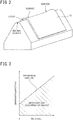
FIG. 2 is a diagram illustrating one example of a state where lift-up from a die has occurred due to the bending; -
FIG. 3 is a diagram illustrating one example of a deformation limit line and a region without occurrence of any crack on a sheared end face; -
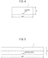
FIG. 4 is a diagram illustrating the shape of a test piece in a V-shaped bending test; -
FIG. 5 is a diagram illustrating the shape of a test piece in a notch tensile test; -
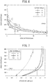
FIG. 6 is a diagram illustrating relationships between crack length and bending radius in the V-shaped bending test; -
FIG. 7 is a diagram illustrating relationships between crack length and stroke amount in the notch tensile test; -
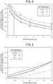
FIG. 8 is a diagram illustrating relationships between maximum principal strain on a crack occurrence portion and bending radius obtained by an FEM analysis of the V-shaped bending test; -
FIG. 9 is a diagram illustrating relationships between maximum principal strain on a crack occurrence portion and bending radius obtained by an FEM analysis of the notch tensile test; -
FIG. 10 is a diagram illustrating relationships between deformation limit strain on the crack occurrence portion and combined stress gradient (index value based on the present invention) obtained from the V-shaped bending test and the notch tensile test; -
FIG. 11 is a diagram illustrating relationships between deformation limit strain on the crack occurrence portion and combined stress gradient (index value based on the present invention) in each forming test; -
FIG. 12 is a diagram illustrating relationships between deformation limit strain on the crack occurrence portion and strain gradient in the in-plane direction in each forming test; and -
FIG. 13 is a diagram illustrating relationships between deformation limit strain on the crack occurrence portion and stress gradient in the in-plane direction in each forming test. - Next, embodiments of the present invention will be described with reference to the drawings.
- The following method according to the present embodiment is applicable even to a position where no bending deformation due to press forming occurs.
FIG. 1 illustrates an example of a formedarticle 10 obtained by forming ametal sheet 1 by press forming including bending.FIG. 1 is the example of a case in which themetal sheet 1 is press formed into a saddle-like shape. InFIG. 1 ,reference sign 1B denotes a bending ridge line that is used as a bending line position when themetal sheet 1 is bent.Reference sign 10A denotes an end face (a sheared end face). Additionally, reference sign Z denotes an example of a place where a crack tends to occur in the vicinity of a boundary between a bending outer surface and the sheared end face. - As in
FIG. 1 , the above bending ridge line is a bending ridge line extending in a direction away from the sheared end face (the sheared surface) by bending (bending deformation) . Hereinafter, the bending ridge line will be also referred to as first bending ridge line. - Note that reference sign Z put at a flat portion in
FIG. 1 is illustrated together as an example of a case where an evaluation position is set on a sheared end face other than a bent portion. - The present inventors conducted various investigations regarding press forming including bending, the result of which is as follows. When the
metal sheet 1 is press formed, a warpage occurs at an end face of themetal sheet 1 at the time of the bending, and the end face side of themetal sheet 1 lifts up from a bending portion of the die, as illustrated inFIG. 2 . Due to this, a center portion side (see reference sign 1Ba inFIG. 1 ) of themetal sheet 1 is subjected to bending deformation with a bending radius close to a bending radius R of the die, whereas the end face side (see reference sign 1Bb inFIG. 1 ) of themetal sheet 1 is subjected to bending deformation with a bending radius different from the bending radius R of the die. - Then, in the case of a combined deformation of bending deformation and tensile deformation, the lift-up of the end face of the
metal sheet 1 from the die tends to reduce as the tensile deformation is increased. However, it has been found that when themetal sheet 1 has a strength of 590 MPa or more or a sheet thickness of 1.0 mm or more, a crack occurs before the lift-up of theend face 10A of themetal sheet 1 is eliminated. Accordingly, it has been shown that the crack prediction methods using the bending radius R of a die, as in the conventional technologies, cannot accurately predict a crack from theend face 10A. - Additionally, bending deformation causes a significantly large stress gradient in a sheet thickness direction X of the
metal sheet 1, due to which a stress gradient in a direction along theend face 10A of themetal sheet 1 and a stress gradient in an in-plane direction orthogonal to theend face 10A become relatively less influential. This has indicated that, in the case of press forming including bending deformation, it is difficult to predict a crack on theend face 10A by the conventional prediction methods using them. - Furthermore, the present inventors expanded a press deformation position to be evaluated, and repeated various investigations regarding the occurrence of a crack on the sheared
end face 10A at bending deformation positions (bending deformation and a combined deformation of bending deformation and tensile deformation) and a deformation position not subjected to bending deformation but subjected to tensile deformation in the press forming including bending described above. As a result, the inventors have found that when, under forming conditions causing a crack on thesheared end face 10A of themetal sheet 1, a maximum principal strain on thesheared end face 10A is defined as limit strain εlimit and a stress gradient in the vicinity of a crack occurrence portion is defined as Δσ, there is a strong correlation between the limit strain εlimit and the stress gradient Δσ in the vicinity of the crack occurrence portion. In addition, the inventors obtained a finding that the occurrence of a crack on the shearedend face 10A can be predicted by comparing strain on the shearedend face 10A during press forming with the limit strain εlimit determined by the stress gradient. - On the basis of the above finding, the inventors have devised an evaluation method for evaluating a deformation limit of the
sheared end face 10A of themetal sheet 1 from an index value obtained from gradients of two surface stress distributions: a gradient of a surface stress distribution in the sheet thickness direction X and a gradient of a surface stress distribution in a direction Y away from thesheared end face 10A (a direction parallel to a bending ridge line direction in the vicinity of bending deformation) in the vicinity Z of the crack occurrence portion, and an end face crack prediction method based on the evaluation method. - In other words, the method of the present embodiment evaluates the deformation limit from an index value obtained from gradients of two surface stress distributions at the evaluation position among stress distributions occurring in the vicinity of the
sheared end face 10A of themetal sheet 1 due to press forming, which gradients are a gradient of a surface stress distribution in the sheet thickness direction X and a gradient of a surface stress distribution in the direction away from thesheared end face 10A. For example, from a relationship between the index value at the evaluation position and a forming limit strain, a deformation limit of the sheared end face 10A is evaluated, and a crack thereof is predicted. - In this case, when the intended press forming includes bending deformation, the gradient of the surface stress distribution in the direction away from the sheared end face 10A may be a gradient of a surface stress distribution in the direction parallel to the bending ridge line direction on the bending outer surface of the
metal sheet 1. - Herein, the method of the present embodiment provides a technology for allowing deformation limit evaluation and crack prediction on the
sheared end face 10A (theend face 10A formed by shearing) to be uniformly and accurately evaluated by one index value in all cases of a simple bending deformation, a combined deformation of tensile deformation and bending deformation, and a tensile deformation on thesheared end face 10A of themetal sheet 1 when press work is carried out. The method of the present embodiment is also intended for thesheared end face 10A at a press work position that does not include bending deformation. - A description will be given of an index value for use in the evaluation that evaluates the deformation limit of the
sheared end face 10A of themetal plate 1 used in the present embodiment and in the prediction of end face cracking based on the evaluation. - The index value of the present embodiment is a value obtained from, as variables, the gradients of the two surface stress distributions including the gradient of the surface stress distribution in the sheet thickness direction X and the gradient of the surface stress distribution in the direction away from the
sheared end face 10A in the vicinity Z of the crack occurrence portion. - Note that the gradient of the surface stress distribution is also simply referred to as stress gradient, and the stress gradient in the direction Y away from the sheared end face 10A is also referred to as stress gradient in the in-plane direction.
- The direction away from the sheared end face 10A is defined as, for example, a normal direction of the
sheared end face 10A or a direction orthogonal to an edge line of the end face (seeFIG. 1 ). The direction away from the sheared end face 10A may be a direction parallel to a closest bending ridge line direction. - The stress gradient in the direction away from the
sheared end face 10A at a deformation position where bending deformation is applied is a stress gradient of a stress distribution that occurs near a boundary between the bending outer surface of themetal sheet 1 subjected to bending and the sheared end face 10A, which is a stress gradient in the direction parallel to the closest bending ridge line direction. The bending outer surface is the surface of a side that is deformed into a protruding shape by bending. - The index value is represented by a function of the following Equation (1) using, as two variables, a stress gradient Δσthickness in the sheet thickness direction X and a stress gradient Δσin-plane in the in-plane direction.
- In the present embodiment, a combined stress Δσcombine is an index value.

- The index value is, for example, an average value of the above two stress gradients, as in the following Equation (2) :

- It has been found that a crack that occurs from the end face 10A correlates with the two stress gradients in the sheet thickness direction X and the in-plane direction in the vicinity Z of the crack occurrence portion. Furthermore, as in Equation (3), the index value Δσcombine comprising a root mean square of the gradients in the two directions highly correlates with cracking of the
end face 10A. Thus, with use of the evaluation value calculated by Equation (3), deformation limit evaluation and end face crack prediction of thesheared end face 10A can be performed with high accuracy.
- Additionally, as a simple method, a sum of the two stress gradients in the sheet thickness direction X and the in-plane direction Y may be used as an index value, as in Equation (4) :

- Herein, the above-mentioned Equation (2) is an example of a case when obtaining an index value from the two stress gradients, the two stress gradients are averaged by simple averaging. From the viewpoint that, in the case of bending, the stress gradient in the sheet thickness direction X more highly contributes to evaluation of cracking, each stress gradient may be weighted in accordance with bending deformation to obtain an index value, as in Equation (5).

- Herein, "a" and "b" represent weighting factors, and in the case of bending, the relationship of a > b is set. For example, it is set to a = 1.3 and b = 0.7. In the case of simple tensile deformation, for example, the relationship of a < b is set. For example, it is set to a = 0.7 and b = 1.3.
- Similarly, also in Equation (3) and Equation (4), the two stress gradients may be weighted as mentioned above.
- Each stress gradient is calculated, for example, as follows.
- For example, the stress gradients of the crack occurrence portion are obtained by an FEM analysis result of forming conditions in crack determination. As the stress gradients of the crack occurrence portion, stress gradients in two directions: the sheet thickness direction X and the in-plane direction that is the normal direction of the
sheared end face 10A of a finite element model of a test piece are obtained from a finite element whose deformation limit strain has been obtained. The range for obtaining the stress gradients is set to a crack length that is a crack determination criterion. Note that the range for calculating the gradients is preferably 10 mm or less, and more preferably 5 mm or less. - Herein, when the press forming is a press forming including a bending deformation that forms a bending ridge line extending in the direction away from the
sheared end face 10A (the first bending ridge line), for example, the gradient of the surface stress distribution in the direction away from the sheared surface may be a gradient of a surface stress distribution in a direction parallel to the direction of the first bending ridge line on the bending outer surface of the metal sheet. In this case, if at least one other bending ridge line different from the first bending ridge line is present within a range for evaluating the gradient of the surface stress distribution in the direction parallel to the first bending ridge line, it is preferable to calculate the gradient of the surface stress distribution at a distance up to less than an intersection closest to the sheared surface among intersections between the direction parallel to the first bending ridge line and the at least one other bending ridge line. The reason for that is that the intersection between the two bending ridge lines exhibits high stress by deformation due to protruding deformation, and influence of a portion beyond the intersection on the deformation limit of the sheared end face is very small with respect to the sheared end face. Additionally, the intersection between the direction parallel to the first bending ridge line (except for the first bending ridge line direction) and the other bending ridge line exhibits locally higher stress than at positions less than the intersection. Thus, even in the direction parallel to the first bending ridge line (except for the first bending ridge line direction), the gradient of the surface stress distribution is preferably calculated within the range of a distance up to less than the intersection. - As each stress gradient, it is desirable to obtain equivalent plastic strains from the FEM analysis result, and calculate equivalent stresses by using an equivalent stress-equivalent plastic strain relationship of the
metal sheet 1 to obtain an average gradient thereof. By doing this, the stress gradient in the sheet thickness direction X and the stress gradient in the in-plane direction are calculated on the basis of a position where deformation limit strain is obtained. - In this way, the two surface strains in the sheet thickness direction X and the direction away from the sheared end face are calculated by forming simulation, and then, the stress gradient in the sheet thickness direction X and the stress gradient in the direction away from the sheared end face are obtained from the calculated each surface strain.
- Herein, the surface strains for obtaining the stress gradients may be obtained by actually conducting a forming test.
- Then, the above-described index value is calculated that comprises the combined stress gradient simultaneously considering the stress gradients in the sheet thickness direction X and the in-plane direction.
- Herein, on the basis of the FEM analysis result of forming conditions and the like, a position where a crack is expected to occur when the end face deforms is set as an evaluation position.
- To determine the deformation limit of the
sheared end face 10A, it is necessary to prepare a test piece including the shearedend face 10A and conduct two or more kinds of tests in which stress gradients occurring during deformation are different. - Desirable testing methods are a V-shaped bending test in which the stress gradient in the vicinity of the
sheared end face 10A during deformation is large and a notch tensile test in which the stress gradient in the vicinity of thesheared end face 10A during deformation is small. However, any testing method can be conducted as long as test pieces including the shearedend face 10A formed under the same conditions can be subjected to deformations with different stress gradients and the tests can be reproduced by an FEM analysis that will be described later. - Before starting the tests, a crack determination criterion for each forming test is determined. The method for determining the crack determination criterion is not particularly limited, and any determination criterion may be used. Examples of the determination method include a method of prescribing a crack length for crack determination, a method of prescribing a ratio of crack length to sheet thickness, and a method of determining a crack by crack penetration in the sheet thickness direction X.
- After conducting each forming test, the length of a crack that has occurred at the sheared end face 10A is measured to obtain a relationship between crack length and forming conditions.
- Next, FEM analysis is conducted under the same conditions . In the analysis result, a maximum principal strain is obtained from the finite element of the crack occurrence portion of the
sheared end face 10A and a relationship between the maximum principal strain on the crack occurrence portion of the sheared end face 10A and forming conditions is obtained. A maximum principal strain under the forming conditions in the crack determination described above is obtained, and then defined as deformation limit strain. In this way, the deformation limit strain is calculated. - With the above-described method, the relationship between deformation limit strain and stress gradient in the vicinity of the crack occurrence portion in each forming test is obtained. Then, from results of the two or more tests, a relational equation of linear approximation represented by Equation (6) is obtained, and set as a deformation limit line of the sheared end face 10A, as illustrated in
FIG. 3 .
- In the equation, A and B are material constants.
- Note that while this embodiment is an example in which deformation limit strain is set on the vertical axis, another variable correlating with the index value may be set on the vertical axis. Examples of the other variable include tension. Additionally, the deformation limit strain is not particularly limited to one defined by the maximum principal strain as described above. For example, the deformation limit strain may be one defined by an equivalent plastic strain.
- An FEM analysis of press forming is conducted to calculate a maximum principal strain εedge of the
sheared end face 10A at the evaluation position where crack determination is desired, the stress gradient Δσthickness in the sheet thickness direction X, and the stress gradient Δσin-plane in the in-plane direction. In addition, as described above, the deformation limit strain εlim at the index value Δσcombine is calculated, and a comparison is made between the maximum principal strain εedge and the deformation limit strain εlim of thesheared end face 10A at the evaluation position where crack determination is desired, thereby determining a crack. Specifically, a prediction (determination) is made that a crack occurs when satisfying the condition of Equation (7) :
- Herein, a description will be given of the
sheared end face 10A after shearing. - Shearing is a method for separating the
metal sheet 1 into two or more pieces by subjecting themetal sheet 1 to shear deformation using a pair of a punch and a die to cause cracking. - In the present embodiment, the
metal sheet 1 including the sheared end face 10A is produced by shearing into a predetermined outline shape through an ordinary shearing process. - Although properties of the
sheared end face 10A subjected to shearing vary in accordance with a clearance that is a distance between the punch and the die, the present embodiment is not limited to the properties of the end face. However, the clearance is preferably set within a range of from 5 to 20% of the sheet thickness of themetal sheet 1 where processing load is low and thereby damage to the punch and the die is reduced. Particularly, a range of from 8 to 15% is preferably set for a steel sheet having a tensile strength of 590 MPa or more. In addition, there is also a method of widely forming thesheared end face 10A by shearing with a clearance of 5% or less. However, shearing may be performed by any method to produce the test piece (the metal sheet 1) to be evaluated. - According to the present embodiment, the deformation limit of the
sheared end face 10A of themetal sheet 1 necessary to press form thetarget metal sheet 1 can be accurately evaluated and predicted. - As a result, according to the present embodiment, an accurate prediction can be made as to whether or not the
metal sheet 1 for use in press forming various parts such as panel parts and structural/framework parts of an automobile is appropriately selected. Then, according to the present embodiment, stable press forming can be performed, as well as a great contribution can be made to reduction in defect rates of press formed articles. Furthermore, according to the present embodiment, the shape of the press die can be accurately predicted at a designing stage, which can contribute to shortening of a press die manufacturing period. - In general, the
metal sheet 1 having high strength is low in ductility, so that deforming thesheared end face 10A of themetal sheet 1 easily causes cracking. Thus, the present invention is more effective as themetal sheet 1 having higher strength is used. Specifically, the invention is preferably directed to themetal sheet 1 having a tensile strength of 590 MPa or more, and more preferably to themetal sheet 1 having a tensile bending strength of 980 MPa or more. In addition, a type of themetal sheet 1 that is to be mass-produced, as in press forming, is an advantageous target in terms of cost, and it is preferable to target themetal sheet 1, and particularly a steel sheet. - Next, Examples based on the present invention will be described.
- As test pieces, three kinds of test materials A, B, and C depicted in Table 1 were used. Table 1 gives material characteristics of each test material.
Table 1 Test material Yield stress YS [MPa] Tensile strength TS [MPa] Elongation El [%] Sheet thickness [mm] A 924 1285 11.5 1.4 B 985 1194 16.6 1.2 C 1183 1353 8.1 1.6 - A punched hole was formed in each test material, and then the each test material was formed by cutting into a predetermined test piece shape. The punching clearance is preferably from 5% to 20% of the sheet thickness . In the case of a clearance less than 5% thereof, a secondary sheared surface can be formed, whereas in the case of a clearance more than 20% thereof, formation of burrs can be noticeable. Additionally, the secondary sheared surface and the noticeable burrs are not preferable since they serve as an origin of occurrence of a crack, and thereby destabilize and reduce moldability of the end face. This is also not preferable as a clearance in mass production of parts. For stable moldability, the clearance is more preferably set in a narrower range of from 10% to 15%.
-
FIG. 4 illustrates a test piece shape for a V-shaped bending test, andFIG. 5 illustrates a test piece shape for a notch tensile test. Additionally, the dimensional unit given in each drawing is mm. - The test pieces of
FIG. 4 and FIG. 5 were subjected to the V-shaped bending test and the notch tensile test to obtain relationships between crack lengths of the sheared end face 10A and forming conditions, as inFIG. 6 and FIG. 7 . - In the present Example, test results of crack lengths of 200 µm or more were determined to be cracks. However, as described above, the determination criterion can be optionally determined, and there is no restriction due to crack length. The crack length for the determination criterion may be set to 100% of the sheet thickness or 50% thereof. Note that, to reduce the defect rate of a target pressed part, it is better to determine a shorter crack length as a crack. In this case, 50% or less of the sheet thickness is preferable, and 30% or less thereof is more preferable.
- With the crack determination, forming conditions at the time of crack determination in each test were determined.
- Next, through an FEM analysis reproducing the each test, relationships between surface strains and forming conditions, as in
FIG. 8 and FIG. 9 , were obtained. Table 2 depicts the obtained results regarding deformation limit strains under the crack determination conditions of the V-shaped bending test and the notch tensile test.Table 2 Test material Deformation limit strain εlimit V-shaped bending test Notch tensile test A 0.51 0.21 B 0.55 0.21 C 0.46 0.02 - Furthermore, from the FEM analysis results under the forming conditions at the time of the crack determination, stress gradients in the sheet thickness direction X in the vicinity of the crack occurrence portion and the in-plane direction that is the normal direction of the sheared end face 10A were obtained to obtain a relationship between deformation limit strain and combined stress gradient as index value in the vicinity of the crack occurrence portion (use of Equation (3)), the result of which is depicted in
FIG. 10 . - From the result of
FIG. 10 , the presence or absence of occurrence of a crack on thesheared end face 10A can be predicted by reproducing other forming conditions through an FEM analysis and obtaining strains and stress gradients of thesheared end face 10A. - As one example,
FIG. 11 illustrates a result obtained by superimposing, onFIG. 10 , relationships between deformation limit strains and stress gradients in the vicinity of a crack occurrence portion at the time of deformation limit in a conical hole expansion test and a hat-shaped drawing test. - As can be seen in
FIG. 11 , the deformation limit of each test is positioned in the vicinity of the relationship between deformation limit strain and stress gradient, indicating that a crack limit can be predicted with high accuracy. -
FIG. 12 illustrates a result obtained by summing up relationships between deformation limit strain and strain gradient Δεin-plane in the sheet in-plane direction. -
FIG. 12 indicates that directly adopting the method ofPTL 1 using the strain gradient Δεin-plane in the sheet in-plane direction reduces prediction accuracy. -
FIG. 13 illustrates a result obtained by summing up relationships between deformation limit strain and stress gradient Δσin-plane in the sheet in-plane direction. -
FIG. 13 indicates that directly adopting the method ofPTL 1 using the stress gradient Δσin-plane in the sheet in-plane direction reduces prediction accuracy. - It can be seen that, as described above, the deformation limit evaluation method and the crack prediction method according to the present invention are more accurate than Comparative Examples 1 and 2.
- The present Example has described the example of application of steel sheets having a tensile strength of 980 MPa class or more, and the present invention is preferably applied to press forming of such high-strength steel sheets, but not limited to the above materials. The invention can also be widely applied to
metal sheets 1, such as steel sheets having a tensile strength of 590 MPa class or more and aluminum sheets. - The entire contents of Japanese Patent Application No.
2017-184706 (filed on Sep. 26, 2017 -
- 1: Metal sheet
- 1B: Bending ridge line (first bending ridge line)
- 10: Formed article
- 10A: Sheared end face (sheared surface)
- X: Sheet thickness direction
- Y: Direction away from sheared end face (in-plane direction)
Claims (10)
- A deformation limit evaluation method for, when deforming by press forming a metal sheet subjected to shearing, evaluating a deformation limit of a sheared surface of the metal sheet comprising:
evaluating the deformation limit by an index value obtained from gradients of two surface stress distributions at an evaluation position among stress distributions occurring in a vicinity of the sheared surface of the metal sheet due to the press forming, which gradients are a gradient of a surface stress distribution in a sheet thickness direction and a gradient of a surface stress distribution in a direction away from the sheared surface. - The deformation limit evaluation method according to claim 1, wherein
the press forming is a press forming including a bending deformation, the bending deformation forming a bending ridge line extending in the direction away from the sheared surface, and wherein the gradient of the surface stress distribution in the direction away from the sheared surface is a gradient of a surface stress distribution in a direction parallel to the direction of the bending ridge line on a bending outer surface of the metal sheet. - The deformation limit evaluation method according to claim 2, wherein
when the bending ridge line extending in the direction away from the sheared surface is referred to as first bending ridge line, if at least one other bending ridge line different from the first bending ridge line is present within a range for evaluating the gradient of the surface stress distribution in the direction parallel to the first bending ridge line, the gradient of the surface stress distribution is calculated at a distance up to less than an intersection closest to the sheared surface among intersections between the first bending ridge line and the at least one other bending ridge line. - The deformation limit evaluation method according to any one of claims 1 to 3, wherein
the deformation limit of the sheared surface is evaluated from a relationship between the index value at the evaluation position and a deformation limit strain on the sheared surface. - The deformation limit evaluation method according to any one of claims 1 to 4, wherein
the index value is a root mean square of the gradients of the two surface stress distributions. - The deformation limit evaluation method according to any one of claims 1 to 4, wherein
the index value is a sum of the gradients of the two surface stress distributions. - The deformation limit evaluation method according to any one of claims 1 to 6, wherein
two surface strains in the sheet thickness direction and the direction away from the sheared surface are calculated by forming simulation, and the gradients of the two surface stress distributions are obtained from the respective calculated surface strains. - The deformation limit evaluation method according to any one of claims 1 to 7, wherein
the evaluation position is a position where a crack is expected to occur when the end face deforms. - A crack prediction method for predicting a presence or absence of a crack when deforming by press forming a metal sheet subjected to shearing comprising:previously obtaining a relationship between an index value obtained from, as variables, gradients of two surface stress distributions among stress distributions occurring in a vicinity of a sheared surface of the metal sheet due to the press forming, which gradients are a gradient of a surface stress distribution in a sheet thickness direction and a gradient of a surface stress distribution in a direction away from the sheared surface, and a limit strain on the sheared surface; andpredicting a crack on the sheared surface from the relationship and the index value obtained from the gradients of the two surface stress distributions at an evaluation position.
- A press die designing method comprising:
designing a press die shape configured to suppress occurrence of a crack on an end face of a metal sheet by using the deformation limit evaluation method according to any one of claims 1 to 8 or the crack prediction method according to claim 9.
Applications Claiming Priority (2)
| Application Number | Priority Date | Filing Date | Title |
|---|---|---|---|
| JP2017184706 | 2017-09-26 | ||
| PCT/JP2018/029131 WO2019064922A1 (en) | 2017-09-26 | 2018-08-02 | Method for evaluating deformation limit, crack prediction method, and method for designing press die |
Publications (2)
| Publication Number | Publication Date |
|---|---|
| EP3689491A1 true EP3689491A1 (en) | 2020-08-05 |
| EP3689491A4 EP3689491A4 (en) | 2020-11-25 |
Family
ID=65901357
Family Applications (1)
| Application Number | Title | Priority Date | Filing Date |
|---|---|---|---|
| EP18861608.0A Withdrawn EP3689491A4 (en) | 2017-09-26 | 2018-08-02 | METHODS FOR EVALUATING THE DEFORMING LIMIT, Crack PREDICTION METHODS AND METHODS FOR DESIGNING A PRESSING DIE |
Country Status (7)
| Country | Link |
|---|---|
| US (1) | US11590591B2 (en) |
| EP (1) | EP3689491A4 (en) |
| JP (1) | JP6769561B2 (en) |
| KR (1) | KR102345288B1 (en) |
| CN (1) | CN111163875B (en) |
| MX (1) | MX2020003456A (en) |
| WO (1) | WO2019064922A1 (en) |
Families Citing this family (17)
| Publication number | Priority date | Publication date | Assignee | Title |
|---|---|---|---|---|
| CN113453818B (en) | 2019-02-26 | 2023-11-28 | 杰富意钢铁株式会社 | Bending crack evaluation method, system therefor and manufacturing method of stamped formed parts |
| JP6819832B1 (en) * | 2019-03-14 | 2021-01-27 | Jfeスチール株式会社 | Stretch flange crack evaluation method, metal plate selection method, press die design method, part shape design method, and press part manufacturing method |
| CN114080280B (en) * | 2019-07-12 | 2024-01-12 | 日本制铁株式会社 | Blank manufacturing method and device, stamping molded product manufacturing method, shape determination method and procedure, and blank |
| US11416045B2 (en) | 2020-04-13 | 2022-08-16 | International Business Machines Corporation | Thermal interface material structures for directing heat in a three-dimensional space |
| CN114323891B (en) * | 2020-09-30 | 2024-05-14 | 宝山钢铁股份有限公司 | Die for forming width characteristic forming limit of roll stamping and evaluation method |
| KR20230098835A (en) * | 2020-12-03 | 2023-07-04 | 제이에프이 스틸 가부시키가이샤 | Delayed fracture characteristic evaluation method, and program |
| CN113032958B (en) * | 2021-02-22 | 2022-04-26 | 中国科学院武汉岩土力学研究所 | A calculation method of mechanical parameters of shear strength of slope soil-rock mixture |
| JP7543536B2 (en) * | 2021-03-03 | 2024-09-02 | 株式会社クラレ | Fracture prediction program and fracture prediction method |
| CN113128001B (en) * | 2021-05-17 | 2022-04-15 | 同济大学 | A formability test method |
| CN113552003B (en) * | 2021-06-17 | 2023-12-12 | 首钢集团有限公司 | Prediction method for edge forming limit of high-strength steel plate stamping part |
| CN114378355B (en) * | 2022-02-25 | 2022-10-14 | 乐捷家居股份有限公司 | Material plate punching and shearing equipment for office furniture processing and punching and shearing method thereof |
| US12036598B2 (en) * | 2022-04-04 | 2024-07-16 | Ford Global Technologies, Llc | Method and system for lubricating and forming a metal component from sheet metal |
| JP7730306B2 (en) * | 2022-07-28 | 2025-08-27 | 株式会社神戸製鋼所 | Sheet metal forming limit evaluation method and crack prediction method |
| CN115071200A (en) * | 2022-08-24 | 2022-09-20 | 深圳市信润富联数字科技有限公司 | Stamping process and die design method, device, equipment and readable storage medium |
| CN115758691B (en) * | 2022-11-07 | 2025-08-15 | 中国北方发动机研究所(天津) | Coordinated evaluation method for deformation of engine cylinder sleeve |
| US12350725B2 (en) * | 2023-06-22 | 2025-07-08 | GM Global Technology Operations LLC | Components produced from metallic blanks and methods for producing the same |
| WO2025022721A1 (en) * | 2023-07-26 | 2025-01-30 | Jfeスチール株式会社 | Method for evaluating delayed fracture characteristic of metal plate for press molding, method for manufacturing press-molded article, and program |
Family Cites Families (12)
| Publication number | Priority date | Publication date | Assignee | Title |
|---|---|---|---|---|
| JP4371985B2 (en) * | 2004-11-30 | 2009-11-25 | 株式会社豊田中央研究所 | Stress analysis method, program, and recording medium |
| JP5146395B2 (en) | 2008-08-20 | 2013-02-20 | 新日鐵住金株式会社 | Stretch flange crack estimation method considering strain gradient and stretch flange crack judgment system of press forming simulation |
| JP5294082B2 (en) | 2009-08-24 | 2013-09-18 | 新日鐵住金株式会社 | Bending limit strain measurement method, bending crack determination method, and bending crack determination program |
| JP5435352B2 (en) | 2010-01-08 | 2014-03-05 | 新日鐵住金株式会社 | Method for determining the breaking strain of plate materials |
| JP5630311B2 (en) * | 2011-02-16 | 2014-11-26 | Jfeスチール株式会社 | Method for predicting cracks in press molding and method for manufacturing pressed parts |
| JP5375941B2 (en) * | 2011-12-21 | 2013-12-25 | Jfeスチール株式会社 | Press molding tool design method, press molding tool |
| JP5472518B1 (en) | 2012-11-19 | 2014-04-16 | Jfeスチール株式会社 | Method for determining limit strain of stretch flange and method for determining press forming possibility |
| WO2014208697A1 (en) * | 2013-06-26 | 2014-12-31 | 新日鐵住金株式会社 | Method for determining bending fracture in metal plate, program, and storage medium |
| WO2015191678A1 (en) | 2014-06-11 | 2015-12-17 | Magna International Inc. | Performing and communicating sheet metal simulations employing a combination of factors |
| EP3165298A4 (en) | 2014-07-02 | 2018-03-07 | Nippon Steel & Sumitomo Metal Corporation | Stretch-flange crack prediction method, stretch-flange crack prediction device, computer program, and recording medium |
| CN105574301A (en) * | 2016-02-25 | 2016-05-11 | 成都亨通兆业精密机械有限公司 | Design method for automobile covering part drawing die |
| JP2017184706A (en) | 2016-04-05 | 2017-10-12 | 一繁 松永 | Buoyancy adjuster of landing net |
-
2018
- 2018-08-02 US US16/649,866 patent/US11590591B2/en active Active
- 2018-08-02 KR KR1020207008715A patent/KR102345288B1/en active Active
- 2018-08-02 WO PCT/JP2018/029131 patent/WO2019064922A1/en not_active Ceased
- 2018-08-02 JP JP2019544372A patent/JP6769561B2/en active Active
- 2018-08-02 CN CN201880061927.2A patent/CN111163875B/en active Active
- 2018-08-02 EP EP18861608.0A patent/EP3689491A4/en not_active Withdrawn
- 2018-08-02 MX MX2020003456A patent/MX2020003456A/en unknown
Also Published As
| Publication number | Publication date |
|---|---|
| CN111163875A (en) | 2020-05-15 |
| US11590591B2 (en) | 2023-02-28 |
| JPWO2019064922A1 (en) | 2020-01-16 |
| KR102345288B1 (en) | 2021-12-29 |
| JP6769561B2 (en) | 2020-10-14 |
| KR20200044903A (en) | 2020-04-29 |
| CN111163875B (en) | 2021-09-07 |
| MX2020003456A (en) | 2020-08-03 |
| US20200276658A1 (en) | 2020-09-03 |
| WO2019064922A1 (en) | 2019-04-04 |
| EP3689491A4 (en) | 2020-11-25 |
Similar Documents
| Publication | Publication Date | Title |
|---|---|---|
| US11590591B2 (en) | Press die designing method using an index value obtained from two stress gradients in sheet thickness direction and gradient of surface stress distribution in direction | |
| US12275052B2 (en) | Pressed component manufacturing method | |
| EP3674009A1 (en) | Deformation limit evaluation method for sheared surface of metallic sheet, crack prediction method, and press die designing method | |
| CN110740821B (en) | Evaluation method of deformation limit of metal plate in shearing plane, crack prediction method and design method of stamping metal die | |
| US11971390B2 (en) | Stretch flange crack evaluation method, metal sheet selection method, press die design method, component shape design method, and pressed component manufacturing method | |
| JP2009061477A (en) | Estimation method of stretch flange crack in thin plate press forming simulation | |
| Le et al. | Analysis of sheared edge formability of aluminum | |
| JP6246074B2 (en) | Tensile compression test method for high strength steel sheet | |
| US20250305919A1 (en) | Method for assessing delayed fracture characteristics of sheared end surface, program, and method for producing automotive components | |
| US12017265B2 (en) | Method for evaluating bending crack, system for evaluating bending crack, and method for manufacturing press-formed component | |
| Yoshida et al. | Evaluation and improving methods of stretch flangeability | |
| EP4112201A1 (en) | Press forming method and shape evaluation method for press formed article | |
| JP4987362B2 (en) | Hat-type metal parts and manufacturing method thereof | |
| JP4510572B2 (en) | Manufacturing method for automotive parts having punched end faces with excellent fatigue characteristics | |
| EP4733740A1 (en) | Method for evaluating delayed fracture characteristic of metal plate for press molding, method for manufacturing press-molded article, and program | |
| JP7541657B1 (en) | Method for evaluating delayed fracture, method for predicting delayed fracture, method for manufacturing press-molded product, and program | |
| JP5145689B2 (en) | Blank for press molding of hat-shaped metal parts | |
| EP4685457A1 (en) | Delayed fracture characteristic evaluation method, delayed fracture prediction method, program, and press-molded article production method | |
| WO2024224677A1 (en) | Delayed fracture characteristic evaluation method, delayed fracture prediction method, program, press-molded article production method, and shearing device | |
| JP2006224122A (en) | Thin steel sheet blank with excellent punch end face formability and fatigue characteristics |
Legal Events
| Date | Code | Title | Description |
|---|---|---|---|
| STAA | Information on the status of an ep patent application or granted ep patent |
Free format text: STATUS: THE INTERNATIONAL PUBLICATION HAS BEEN MADE |
|
| PUAI | Public reference made under article 153(3) epc to a published international application that has entered the european phase |
Free format text: ORIGINAL CODE: 0009012 |
|
| STAA | Information on the status of an ep patent application or granted ep patent |
Free format text: STATUS: REQUEST FOR EXAMINATION WAS MADE |
|
| 17P | Request for examination filed |
Effective date: 20200327 |
|
| AK | Designated contracting states |
Kind code of ref document: A1 Designated state(s): AL AT BE BG CH CY CZ DE DK EE ES FI FR GB GR HR HU IE IS IT LI LT LU LV MC MK MT NL NO PL PT RO RS SE SI SK SM TR |
|
| AX | Request for extension of the european patent |
Extension state: BA ME |
|
| A4 | Supplementary search report drawn up and despatched |
Effective date: 20201028 |
|
| RIC1 | Information provided on ipc code assigned before grant |
Ipc: G06F 30/23 20200101ALI20201022BHEP Ipc: G06F 30/20 20200101AFI20201022BHEP Ipc: G06F 113/24 20200101ALN20201022BHEP |
|
| DAV | Request for validation of the european patent (deleted) | ||
| DAX | Request for extension of the european patent (deleted) | ||
| STAA | Information on the status of an ep patent application or granted ep patent |
Free format text: STATUS: EXAMINATION IS IN PROGRESS |
|
| 17Q | First examination report despatched |
Effective date: 20220615 |
|
| STAA | Information on the status of an ep patent application or granted ep patent |
Free format text: STATUS: THE APPLICATION IS DEEMED TO BE WITHDRAWN |
|
| 18D | Application deemed to be withdrawn |
Effective date: 20250704 |