EP3689264A1 - Chirurgisches klammergerät mit auslenkbarer distaler spitze - Google Patents
Chirurgisches klammergerät mit auslenkbarer distaler spitze Download PDFInfo
- Publication number
- EP3689264A1 EP3689264A1 EP20154700.7A EP20154700A EP3689264A1 EP 3689264 A1 EP3689264 A1 EP 3689264A1 EP 20154700 A EP20154700 A EP 20154700A EP 3689264 A1 EP3689264 A1 EP 3689264A1
- Authority
- EP
- European Patent Office
- Prior art keywords
- tip
- anvil
- end effector
- jaw
- internal
- Prior art date
- Legal status (The legal status is an assumption and is not a legal conclusion. Google has not performed a legal analysis and makes no representation as to the accuracy of the status listed.)
- Granted
Links
- 239000012636 effector Substances 0.000 claims abstract description 267
- 238000000576 coating method Methods 0.000 claims description 16
- 239000011248 coating agent Substances 0.000 claims description 13
- 238000004891 communication Methods 0.000 claims description 10
- 238000010304 firing Methods 0.000 description 45
- 238000000034 method Methods 0.000 description 31
- 238000005520 cutting process Methods 0.000 description 29
- 239000000463 material Substances 0.000 description 20
- 230000033001 locomotion Effects 0.000 description 19
- 230000009977 dual effect Effects 0.000 description 18
- 230000008859 change Effects 0.000 description 13
- 239000010410 layer Substances 0.000 description 8
- 238000012800 visualization Methods 0.000 description 8
- 230000007246 mechanism Effects 0.000 description 7
- 229920001971 elastomer Polymers 0.000 description 6
- 239000000806 elastomer Substances 0.000 description 6
- 239000002184 metal Substances 0.000 description 6
- 238000012986 modification Methods 0.000 description 6
- 230000004048 modification Effects 0.000 description 6
- 239000013536 elastomeric material Substances 0.000 description 5
- 238000003780 insertion Methods 0.000 description 5
- 230000037431 insertion Effects 0.000 description 5
- 210000003484 anatomy Anatomy 0.000 description 4
- 230000008901 benefit Effects 0.000 description 4
- 210000000056 organ Anatomy 0.000 description 4
- 230000005855 radiation Effects 0.000 description 4
- 238000013459 approach Methods 0.000 description 3
- 230000009286 beneficial effect Effects 0.000 description 3
- 238000004140 cleaning Methods 0.000 description 3
- 238000013461 design Methods 0.000 description 3
- 230000014509 gene expression Effects 0.000 description 3
- 238000009434 installation Methods 0.000 description 3
- 230000004044 response Effects 0.000 description 3
- 238000001356 surgical procedure Methods 0.000 description 3
- 230000000007 visual effect Effects 0.000 description 3
- 230000000694 effects Effects 0.000 description 2
- 208000014674 injury Diseases 0.000 description 2
- 238000012544 monitoring process Methods 0.000 description 2
- 230000008569 process Effects 0.000 description 2
- 229910001220 stainless steel Inorganic materials 0.000 description 2
- 239000010935 stainless steel Substances 0.000 description 2
- 210000000115 thoracic cavity Anatomy 0.000 description 2
- 230000008733 trauma Effects 0.000 description 2
- 238000011282 treatment Methods 0.000 description 2
- 241000894006 Bacteria Species 0.000 description 1
- IAYPIBMASNFSPL-UHFFFAOYSA-N Ethylene oxide Chemical compound C1CO1 IAYPIBMASNFSPL-UHFFFAOYSA-N 0.000 description 1
- 239000004775 Tyvek Substances 0.000 description 1
- 229920000690 Tyvek Polymers 0.000 description 1
- 210000001015 abdomen Anatomy 0.000 description 1
- 230000006978 adaptation Effects 0.000 description 1
- 239000000853 adhesive Substances 0.000 description 1
- 230000001070 adhesive effect Effects 0.000 description 1
- 230000005540 biological transmission Effects 0.000 description 1
- 230000015572 biosynthetic process Effects 0.000 description 1
- 230000000740 bleeding effect Effects 0.000 description 1
- 210000004204 blood vessel Anatomy 0.000 description 1
- 210000001124 body fluid Anatomy 0.000 description 1
- 238000012790 confirmation Methods 0.000 description 1
- 230000005574 cross-species transmission Effects 0.000 description 1
- 230000007423 decrease Effects 0.000 description 1
- 239000003814 drug Substances 0.000 description 1
- 229940079593 drug Drugs 0.000 description 1
- 238000002651 drug therapy Methods 0.000 description 1
- 230000005489 elastic deformation Effects 0.000 description 1
- 239000012530 fluid Substances 0.000 description 1
- 210000001035 gastrointestinal tract Anatomy 0.000 description 1
- 238000001415 gene therapy Methods 0.000 description 1
- 238000002955 isolation Methods 0.000 description 1
- 238000005304 joining Methods 0.000 description 1
- 210000004072 lung Anatomy 0.000 description 1
- 230000002980 postoperative effect Effects 0.000 description 1
- 230000002265 prevention Effects 0.000 description 1
- 238000011084 recovery Methods 0.000 description 1
- 239000002356 single layer Substances 0.000 description 1
- 230000001954 sterilising effect Effects 0.000 description 1
- 238000004659 sterilization and disinfection Methods 0.000 description 1
- 230000001360 synchronised effect Effects 0.000 description 1
- 230000001225 therapeutic effect Effects 0.000 description 1
- 238000013519 translation Methods 0.000 description 1
- 238000002604 ultrasonography Methods 0.000 description 1
- 210000001835 viscera Anatomy 0.000 description 1
- 239000011800 void material Substances 0.000 description 1
- 238000003466 welding Methods 0.000 description 1
Images


Classifications
-
- A—HUMAN NECESSITIES
- A61—MEDICAL OR VETERINARY SCIENCE; HYGIENE
- A61B—DIAGNOSIS; SURGERY; IDENTIFICATION
- A61B17/00—Surgical instruments, devices or methods, e.g. tourniquets
- A61B17/068—Surgical staplers, e.g. containing multiple staples or clamps
- A61B17/072—Surgical staplers, e.g. containing multiple staples or clamps for applying a row of staples in a single action, e.g. the staples being applied simultaneously
- A61B17/07207—Surgical staplers, e.g. containing multiple staples or clamps for applying a row of staples in a single action, e.g. the staples being applied simultaneously the staples being applied sequentially
-
- A—HUMAN NECESSITIES
- A61—MEDICAL OR VETERINARY SCIENCE; HYGIENE
- A61B—DIAGNOSIS; SURGERY; IDENTIFICATION
- A61B17/00—Surgical instruments, devices or methods, e.g. tourniquets
- A61B2017/0046—Surgical instruments, devices or methods, e.g. tourniquets with a releasable handle; with handle and operating part separable
-
- A—HUMAN NECESSITIES
- A61—MEDICAL OR VETERINARY SCIENCE; HYGIENE
- A61B—DIAGNOSIS; SURGERY; IDENTIFICATION
- A61B17/00—Surgical instruments, devices or methods, e.g. tourniquets
- A61B2017/00681—Aspects not otherwise provided for
- A61B2017/00738—Aspects not otherwise provided for part of the tool being offset with respect to a main axis, e.g. for better view for the surgeon
-
- A—HUMAN NECESSITIES
- A61—MEDICAL OR VETERINARY SCIENCE; HYGIENE
- A61B—DIAGNOSIS; SURGERY; IDENTIFICATION
- A61B17/00—Surgical instruments, devices or methods, e.g. tourniquets
- A61B17/068—Surgical staplers, e.g. containing multiple staples or clamps
- A61B17/072—Surgical staplers, e.g. containing multiple staples or clamps for applying a row of staples in a single action, e.g. the staples being applied simultaneously
- A61B2017/07214—Stapler heads
- A61B2017/07257—Stapler heads characterised by its anvil
-
- A—HUMAN NECESSITIES
- A61—MEDICAL OR VETERINARY SCIENCE; HYGIENE
- A61B—DIAGNOSIS; SURGERY; IDENTIFICATION
- A61B17/00—Surgical instruments, devices or methods, e.g. tourniquets
- A61B17/068—Surgical staplers, e.g. containing multiple staples or clamps
- A61B17/072—Surgical staplers, e.g. containing multiple staples or clamps for applying a row of staples in a single action, e.g. the staples being applied simultaneously
- A61B2017/07214—Stapler heads
- A61B2017/07271—Stapler heads characterised by its cartridge
-
- A—HUMAN NECESSITIES
- A61—MEDICAL OR VETERINARY SCIENCE; HYGIENE
- A61B—DIAGNOSIS; SURGERY; IDENTIFICATION
- A61B17/00—Surgical instruments, devices or methods, e.g. tourniquets
- A61B17/28—Surgical forceps
- A61B17/2812—Surgical forceps with a single pivotal connection
- A61B17/282—Jaws
- A61B2017/2829—Jaws with a removable cover
-
- A—HUMAN NECESSITIES
- A61—MEDICAL OR VETERINARY SCIENCE; HYGIENE
- A61B—DIAGNOSIS; SURGERY; IDENTIFICATION
- A61B90/00—Instruments, implements or accessories specially adapted for surgery or diagnosis and not covered by any of the groups A61B1/00 - A61B50/00, e.g. for luxation treatment or for protecting wound edges
- A61B90/08—Accessories or related features not otherwise provided for
- A61B2090/0801—Prevention of accidental cutting or pricking
- A61B2090/08021—Prevention of accidental cutting or pricking of the patient or his organs
-
- A—HUMAN NECESSITIES
- A61—MEDICAL OR VETERINARY SCIENCE; HYGIENE
- A61B—DIAGNOSIS; SURGERY; IDENTIFICATION
- A61B90/00—Instruments, implements or accessories specially adapted for surgery or diagnosis and not covered by any of the groups A61B1/00 - A61B50/00, e.g. for luxation treatment or for protecting wound edges
- A61B90/08—Accessories or related features not otherwise provided for
- A61B2090/0817—Spatulas or spatula like extensions
Definitions
- endoscopic surgical instruments may be preferred over traditional open surgical devices since a smaller incision may reduce the post-operative recovery time and complications. Consequently, some endoscopic surgical instruments may be suitable for placement of a distal end effector at a desired surgical site through the cannula of a trocar. These distal end effectors may engage tissue in a number of ways to achieve a diagnostic or therapeutic effect (e.g., endocutter, grasper, cutter, stapler, clip applier, access device, drug/gene therapy delivery device, and energy delivery device using ultrasound, RF, laser, etc.). Endoscopic surgical instruments may include a shaft between the end effector and a handle portion, which is manipulated by the clinician.
- Such a shaft may enable insertion to a desired depth and rotation about the longitudinal axis of the shaft, thereby facilitating positioning of the end effector within the patient. Positioning of an end effector may be further facilitated through inclusion of one or more articulation joints or features, enabling the end effector to be selectively articulated or otherwise deflected relative to the longitudinal axis of the shaft.
- endoscopic surgical instruments include surgical staplers. Some such staplers are operable to clamp down on layers of tissue, cut through the clamped layers of tissue, and drive staples through the layers of tissue to substantially seal the severed layers of tissue together near the severed ends of the tissue layers.
- surgical staplers are disclosed in U.S. Pat. No. 4,805,823 , entitled “Pocket Configuration for Internal Organ Staplers,” issued February 21, 1989; U.S. Pat. No. 5,415,334 , entitled “Surgical Stapler and Staple Cartridge,” issued May 16, 1995; U.S. Pat. No. 5,465,895 , entitled “Surgical Stapler Instrument,” issued November 14, 1995; U.S. Pat. No.
- surgical staplers referred to above are described as being used in endoscopic procedures, it should be understood that such surgical staplers may also be used in open procedures and/or other non-endoscopic procedures.
- a surgical stapler may be inserted through a thoracotomy and thereby between a patient's ribs to reach one or more organs in a thoracic surgical procedure that does not use a trocar as a conduit for the stapler.
- Such procedures may include the use of the stapler to sever and close a vessel leading to a lung. For instance, the vessels leading to an organ may be severed and closed by a stapler before removal of the organ from the thoracic cavity.
- surgical staplers may be used in various other settings and procedures.
- FIGS. 1-7 depict an exemplary surgical stapling and severing instrument (10) that is sized for insertion, in a nonarticulated state as depicted in FIG. 1 , through a trocar cannula to a surgical site in a patient for performing a surgical procedure.
- a trocar may be inserted in a patient's abdomen, between two of the patient's ribs, or elsewhere.
- instrument (10) is used without a trocar.
- instrument (10) may be inserted directly through a thoracotomy or other type of incision.
- Instrument (10) of the present example includes a handle portion (20) connected to a shaft (22).
- Shaft (22) distally terminates in an articulation joint (11), which is further coupled with an end effector (12).
- end effector (12) is distal with respect to the more proximal handle portion (20).
- spatial terms such as “vertical” and “horizontal” are used herein with respect to the drawings. However, surgical instruments are used in many orientations and positions, and these terms are not intended to be limiting and absolute.
- shaft (22) is constructed in accordance with at least some of the teachings of U.S. Pat. No. 9,795,379 , entitled “Surgical Instrument with Multi-Diameter Shaft,” issued October 24, 2017, the disclosure of which is incorporated by reference herein.
- Other suitable configurations for shaft (22) will be apparent to those of ordinary skill in the art in view of the teachings herein.
- articulation joint (11) may be remotely articulated, as depicted in phantom in FIG. 1 , by an articulation control (13), such that end effector (12) may be deflected from the longitudinal axis (LA) of shaft (22) at a desired angle ( ⁇ ). End effector (12) may thereby reach behind an organ or approach tissue from a desired angle or for other reasons.
- articulation joint (11) enables deflection of end effector (12) along a single plane.
- articulation joint (11) enables deflection of end effector along more than one plane.
- Articulation joint (11) and articulation control (13) may be configured in accordance with the teachings of any of the numerous references that are cited herein.
- articulation joint (11) and/or articulation control (13) may have any other suitable configuration.
- articulation control (13) may instead be configured as a knob that rotates about an axis that is perpendicular to the longitudinal axis (LA) of shaft (22).
- articulation joint (11) and/or articulation control (13) are/is constructed and operable in accordance with at least some of the teachings of U.S. Pat. No. 9,186,142 , entitled “Surgical Instrument End Effector Articulation Drive with Pinion and Opposing Racks,” issued on November 17, 2015, the disclosure of which is incorporated by reference herein.
- Articulation joint (11) may also be constructed and operable in accordance with at least some of the teachings of U.S. Pat. No. 9,795,379 , entitled “Surgical Instrument with Multi-Diameter Shaft,” issued October 24, 2017, the disclosure of which is incorporated by reference herein.
- Other suitable forms that articulation joint (11) and articulation control (13) may take will be apparent to those of ordinary skill in the art in view of the teachings herein.
- End effector (12) of the present example includes a lower jaw (16) and an upper jaw in the form of a pivotable anvil (18).
- lower jaw (16) is constructed in accordance with at least some of the teachings of U.S. Pat. No. 9,808,248 , entitled “Installation Features for Surgical Instrument End Effector Cartridge,” issued November 7, 2017, the disclosure of which is incorporated by reference herein.
- Anvil (18) may be constructed in accordance with at least some of the teachings of U.S. Pat. No. 9,517,065 , entitled “Integrated Tissue Positioning and Jaw Alignment Features for Surgical Stapler,” issued on December 13, 2016, the disclosure of which is incorporated by reference herein; at least some of the teachings of U.S. Pat. No.
- Handle portion (20) includes a pistol grip (24) and a closure trigger (26).
- Closure trigger (26) is pivotable toward pistol grip (24) to cause clamping, or closing, of the anvil (18) toward lower jaw (16) of end effector (12).
- Such closing of anvil (18) is provided through a closure tube (32) and a closure ring (33), which both longitudinally translate relative to handle portion (20) in response to pivoting of closure trigger (26) relative to pistol grip (24).
- Closure tube (32) extends along the length of shaft (22); and closure ring (33) is positioned distal to articulation joint (11).
- Articulation joint (11) is operable to communicate/transmit longitudinal movement from closure tube (32) to closure ring (33).
- Handle portion (20) also includes a firing trigger (28).
- An elongate member (not shown) longitudinally extends through shaft (22) and communicates a longitudinal firing motion from handle portion (20) to a firing beam (14) in response to actuation of firing trigger (28).
- This distal translation of firing beam (14) causes the stapling and severing of clamped tissue in end effector (12), as will be described in greater detail below.
- triggers (26, 28) may be released to release the tissue from end effector (12).
- FIGS. 3-6 depict end effector (12) employing an E-beam form of firing beam (14) to perform a number of functions.
- Firing beam (14) may take any other suitable form, including but not limited to non-E-beam forms.
- firing beam (14) includes a transversely oriented upper pin (38), a firing beam cap (44), a transversely oriented middle pin (46), and a distally presented cutting edge (48).
- Upper pin (38) is positioned and translatable within a longitudinal anvil slot (42) of anvil (18).
- Firing beam cap (44) slidably engages a lower surface of lower jaw (16) by having firing beam (14) extend through lower jaw slot (45) (shown in FIG. 4B ) that is formed through lower jaw (16).
- Middle pin (46) slidingly engages a top surface of lower jaw (16), cooperating with firing beam cap (44). Thereby, firing beam (14) affirmatively spaces end effector (12) during firing.
- firing beam (14) may lack upper pin (38), middle pin (46) and/or firing beam cap (44).
- instrument (10) may simply rely on closure ring (33) or some other feature to pivot anvil (18) to a closed position and hold anvil (18) in the closed position while firing beam (14) advances to the distal position.
- firing beam (14) and/or associated lockout features may be constructed and operable in accordance with at least some of the teachings of U.S. Pat. No. 9,717,497 , entitled "Lockout Feature for Movable Cutting Member of Surgical Instrument," issued August 1, 2017, the disclosure of which is incorporated by reference herein.
- Other suitable forms that firing beam (14) may take will be apparent to those of ordinary skill in the art in view of the teachings herein.
- FIG. 3 shows firing beam (14) of the present example proximally positioned and anvil (18) pivoted to an open position, allowing an unspent staple cartridge (37) to be removably installed into a channel of lower jaw (16).
- staple cartridge (37) of this example includes a cartridge body (70), which presents an upper deck (72) and is coupled with a lower cartridge tray (74).
- a vertical slot (49) is formed through part of staple cartridge (37).
- three rows of staple apertures (51) are formed through upper deck (72) on one side of vertical slot (49), with another set of three rows of staple apertures (51) being formed through upper deck (72) on the other side of vertical slot (49).
- a wedge sled (41) and a plurality of staple drivers (43) are captured between cartridge body (70) and tray (74), with wedge sled (41) being located proximal to staple drivers (43).
- Wedge sled (41) is movable longitudinally within staple cartridge (37); while staple drivers (43) are movable vertically within staple cartridge (37).
- Staples (47) are also positioned within cartridge body (70), above corresponding staple drivers (43).
- each staple (47) is driven vertically within cartridge body (70) by a staple driver (43) to drive staple (47) out through an associated staple aperture (51).
- wedge sled (41) presents inclined cam surfaces that urge staple drivers (43) upwardly as wedge sled (41) is driven distally through staple cartridge (37).
- staple cartridge (37) is constructed and operable in accordance with at least some of the teachings of U.S. Pat. No. 9,517,065 , entitled “Integrated Tissue Positioning and Jaw Alignment Features for Surgical Stapler,” issued December 13, 2016, the disclosure of which is incorporated by reference herein.
- staple cartridge (37) may be constructed and operable in accordance with at least some of the teachings of U.S. Pat. No. 9,808,248 , entitled “Installation Features for Surgical Instrument End Effector Cartridge,” issued November 7, 2017, the disclosure of which is incorporated by reference herein.
- Other suitable forms that staple cartridge (37) may take will be apparent to those of ordinary skill in the art in view of the teachings herein.
- firing beam (14) is then advanced in engagement with anvil (18) by having upper pin (38) enter longitudinal anvil slot (42).
- a pusher block (80) (shown in FIG. 5 ) is located at the distal end of firing beam (14), and is configured to engage wedge sled (41) such that wedge sled (41) is pushed distally by pusher block (80) as firing beam (14) is advanced distally through staple cartridge (37) when firing trigger (28) is actuated.
- FIGS. 4A-4B depicts firing beam (14) fully distally translated after completing severing and stapling of tissue.
- staple forming pockets (53) are intentionally omitted from the view in FIGS. 4A-4B ; but staple forming pockets (53) are shown in FIG. 3 . It should also be understood that anvil (18) is intentionally omitted from the view in FIG. 5 .
- FIG. 7 shows end effector (12) having been actuated through a single stroke through tissue (90).
- cutting edge (48) (obscured in FIG. 7 ) has cut through tissue (90), while staple drivers (43) have driven three alternating rows of staples (47) through the tissue (90) on each side of the cut line produced by cutting edge (48).
- Staples (47) are all oriented substantially parallel to the cut line in this example, though it should be understood that staples (47) may be positioned at any suitable orientations.
- end effector (12) is withdrawn from the trocar after the first stroke is complete, spent staple cartridge (37) is replaced with a new staple cartridge, and end effector (12) is then again inserted through the trocar to reach the stapling site for further cutting and stapling. This process may be repeated until the desired amount of cuts and staples (47) have been provided.
- Anvil (18) may need to be closed to facilitate insertion and withdrawal through the trocar; and anvil (18) may need to be opened to facilitate replacement of staple cartridge (37).
- cutting edge (48) may sever tissue substantially contemporaneously with staples (47) being driven through tissue during each actuation stroke.
- cutting edge (48) just slightly lags behind driving of staples (47), such that a staple (47) is driven through the tissue just before cutting edge (48) passes through the same region of tissue, though it should be understood that this order may be reversed or that cutting edge (48) may be directly synchronized with adjacent staples.
- FIG. 7 shows end effector (12) being actuated in two layers (92, 94) of tissue (90), it should be understood that end effector (12) may be actuated through a single layer of tissue (90) or more than two layers (92, 94) of tissue.
- FIG. 7 shows end effector (12) being actuated in two substantially flat, apposed planar layers (92, 94) of tissue, it should be understood that end effector (12) may also be actuated across a tubular structure such as a blood vessel, a section of the gastrointestinal tract, etc.
- FIG. 7 should therefore not be viewed as demonstrating any limitation on the contemplated uses for end effector (12).
- instrument (10) may be used will be apparent to those of ordinary skill in the art in view of the teachings herein.
- instrument (10) provides motorized control of firing beam (14).
- Exemplary components that may be used to provide motorized control of firing beam (14) are shown and described in U.S. Pat. No. 9,622,746 , entitled “Distal Tip Features for End Effector of Surgical Instrument,” issued April 18, 2017, the disclosure of which is incorporated by reference herein.
- at least part of the motorized control may be configured in accordance with at least some of the teachings of U.S. Pat. No. 8,210,411 , entitled “Motor-Driven Surgical Instrument,” issued July 3, 2012, the disclosure of which is incorporated by reference herein.
- firing beam (14) may be configured in accordance with at least some of the teachings of U.S. Pat. No. 8,453,914 , the disclosure of which is incorporated by reference herein; and/or in accordance with at least some of the teachings of U.S. Pat. No. 8,453,914 , the disclosure of which is also incorporated by reference herein.
- Other suitable components, features, and configurations for providing motorization of firing beam (14) will be apparent to those of ordinary skill in the art in view of the teachings herein. It should also be understood that some other versions may provide manual driving of firing beam (14), such that a motor may be omitted.
- firing beam (14) may be actuated in accordance with at least some of the teachings of any other patent/publication reference cited herein.
- Instrument (10) may also include a lockout switch and lockout indicator as shown and described in U.S. Pat. No. 9,622,746 , entitled “Distal Tip Features for End Effector of Surgical Instrument,” issued April 18, 2017, the disclosure of which is incorporated by reference herein. Additionally, a lockout switch and/or lockout indication and associated components/functionality may be configured in accordance with at least some of the teachings of U.S. Pat. No. 7,644,848 , entitled “Electronic Lockouts and Surgical Instrument Including Same,” issued January 12, 2010, the disclosure of which is incorporated by reference herein.
- Instrument (10) also include a manual return switch (116) configured to act as a "bailout” feature, enabling the operator to quickly begin retracting firing beam (14) proximally during a firing stroke.
- manual return switch (116) may be manually actuated when firing beam (14) has only been partially advanced distally.
- Manual return switch (116) may provide further functionality in accordance with at least some of the teachings of U.S. Pat. No. 9,622,746 , entitled “Distal Tip Features for End Effector of Surgical Instrument," issued April 18, 2017, the disclosure of which is incorporated by reference herein.
- anvil (18) pivots about an axis that is defined by a pin (or similar feature) that slides along an elongate slot or channel as anvil (18) moves toward lower jaw (16).
- the pivot axis translates along the path defined by the slot or channel while anvil (18) simultaneously pivots about that axis.
- the pivot axis may slide along the slot/channel first, with anvil (18) then pivoting about the pivot axis after the pivot axis has slid a certain distance along the slot/channel.
- pivotal movement is encompassed within terms such as “pivot,” “pivots,” “pivotal,” “pivotable,” “pivoting,” and the like.
- some versions may provide pivotal movement of anvil (18) about an axis that remains fixed and does not translate within a slot or channel, etc.
- instrument (10) may be configured and operable in accordance with any of the teachings of U.S. Pat. No. 4,805,823 ; U.S. Pat. No. 5,415,334 ; U.S. Pat. No. 5,465,895 ; U.S. Pat. No. 5,597,107 ; U.S. Pat. No. 5,632,432 ; U.S. Pat. No. 5,673,840 ; U.S. Pat. No. 5,704,534 ; U.S. Pat. No. 5,814,055 ; U.S. Pat. No. 6,978,921 ; U.S. Pat. No. 7,000,818 ; U.S. Pat. No. 7,143,923 ; U.S.
- end effector (12) it may be desirable to provide the user with better visualization of end effector (12).
- end effector (12) as end effector (12) is inserted into a surgical site, the user may rotate shaft (22) of instrument (10) during the procedure. As a result, end effector (12) also rotates. As end effector (12) rotates, it may be desirable for the user to have visual access to the surgical site. For instance, the user may wish to see the interface or contact between tissue (90) and end effector (12). Since end effector (12) may be rotated about the longitudinal axis (LA) relative to handle portion (20), the user may view the surgical site such that lower jaw (16) of end effector is visible rather than anvil (18).
- LA longitudinal axis
- end effector (12) could be rotated such that when the user views end effector (12), anvil (18) is visible by the user. It may be desirable to provide visibility of the surgical site for the user beyond what is possible in instrument (10) of FIG. 1 . For instance, in the case of some surgical procedures where fluid carrying vessels are transected and stapled, it may be desirable to have visual confirmation that anvil (18) and lower jaw (16) completely cover the vessel to be cut, such that the vessel may be fully cut and stapled in one single actuation. In other words, the user may wish to avoid cutting and stapling only a portion of a vessel.
- end effector (12) may be desirable so that the user will know that end effector (12) has been positioned properly within the surgical site for anvil (18) and lower jaw (16) to fully clamp the vessel.
- One potential way of monitoring the surgical site may include improving visualization of the area adjacent to the distal tip of lower jaw (16) and anvil (18).
- end effector (12) may be desirable, but also it may be desirable to construct end effector (12) such that the distal end of anvil (18) is configured to urge tissue (e.g., a large vessel) proximally into the space between anvil (18) and lower jaw (16) as anvil (18) closes toward lower jaw (16).
- FIG. 8 depicts an exemplary end effector (212) comprising an anvil (218) and a lower jaw (216). It will be appreciated that end effector (212) may be used in place of end effector (12) of instrument (10). End effector (212) may be integrally formed with instrument (10) or in the alternative may be interchangeable with end effector (12) of instrument (10).
- Anvil (218) is operable to pivot relative to lower jaw (216).
- Anvil (218) and lower jaw (216) may clamp tissue (90) similarly to clamping performed by anvil (18) and lower jaw (16) shown in FIG. 1 .
- End effector (212) further comprises a cartridge (237) operable to be placed in lower jaw (216) similarly to cartridge (37) shown in FIG. 3 .
- Anvil (218) as can be seen in FIGS. 8-10 has an elongated shape where the distal portion of anvil (218) angles toward cartridge (237).
- the distal portion of anvil (218) angles toward cartridge (237) such that the distal most tip (219) of anvil (218) extends distally longitudinally further than cartridge (237).
- distal tip (219) may extend to a distance longitudinally equal to cartridge (237) or proximal relative to the distal most point on cartridge (237).
- anvil (218) angles toward cartridge (237) through a gentle slope.
- anvil (218) includes sides (241) that taper as they approach the distal most tip (219) of anvil (218).
- anvil (218) is shaped in FIG. 8 similarly to an inverted ski tip.
- the angled shape of anvil (218) may provide easier insertion of end effector (212) into a surgical site.
- the gentle slope or inverted ski tip shape of anvil (218) may provide an atraumatic tissue deflection surface as anvil (218) contacts or moves through tissue.
- Such atraumatic tissue deflection may include urging tissue (e.g., a large vessel) proximally into the space between anvil (218) and lower jaw (216) as anvil (218) closes toward lower jaw (216).
- anvil (218) may also provide better maneuverability of end effector (212) and better visibility of the distal end of end effector (212) in relation to anatomical structures at the surgical site.
- Other suitable variations of anvil (218) will be apparent to one of ordinary skill in the art in view of the teachings herein.
- Cartridge (237) is operable to hold staples similar to staples (47) shown in FIG. 4A for driving into tissue.
- the distal end of cartridge (237) has a triangular profile.
- the distal end of cartridge (237) comprises an upper tapered surface (239) and a lower tapered surface (238).
- the distal end of cartridge (237) comprises a tapered side surface (243) on each side.
- each tapered side surface (243) of cartridge (237) generally aligns with the taper presented by sides (241) of anvil (218).
- side surfaces (243) of cartridge (237) do not extend outwardly from longitudinal axis (LA) of end effector (212) past sides (241) of anvil (218).
- Upper tapered surface (239) and lower tapered surface (238) lead to the distal most end of cartridge (237).
- Lower tapered surface (238) defines a sight line (240) such that once end effector (212) is inserted into a surgical site, the user can see along sight line (240).
- Sight line (240) extends along the edge of lower tapered surface (238). It will be appreciated that the planar shape of lower tapered surface (238) may be operable to allow the user to visualize and/or nearly visualize the distal tip (219) of anvil (218).
- sight line (240) intersects longitudinal axis (LA), which extends longitudinally through end effector (212), to form a viewing angle ( ⁇ ).
- Viewing angle ( ⁇ ) may establish the relative visibility that a user has regarding distal tip (219).
- the user can see in front of distal tip (219) along any line of sight that passes through the intersection of sight line (240) and longitudinal axis (LA) within viewing angle ( ⁇ ).
- viewing angle ( ⁇ ) defines an angle greater than 90 degrees.
- viewing angle ( ⁇ ) defines an angle greater than 135 degrees.
- the user generally looks along sight line (240) or along some other line of sight within viewing angle ( ⁇ ), thus, the user has visibility along sight line as well as any area within viewing angle ( ⁇ ).
- the underside of distal tip (219) is further slightly rounded to aid in the visibility of the intersection of longitudinal axis (LA) and sight line (240).
- end effector (212) may be rotated before, during, or after clamping tissue (90).
- the tapered shape of anvil (218) may also provide more accessible viewing of distal tip (219) or substantially adjacent distal tip (219).
- the taper of anvil (218) along with lower tapered surface (238) of cartridge (237) may further promote easy insertion of end effector (212) into tissue in an atraumatic manner.
- lower tapered surface (238) and the tapered shape of anvil (218) may provide a lead-in, guiding the rest of end effector (212) into the trocar.
- visibility and maneuverability can be enhanced by the tapered design for both sides (241) of anvil (218) and each side (243) of cartridge (237).
- end effector (212) and versions of instrument (10) incorporating end effector (212) may be configured and operable in accordance with at least some of the teachings of U.S. Pat. No. 9,186,142 , entitled “Surgical Instrument End Effector Articulation Drive with Pinion and Opposing Racks,” issued November 17, 2015, the disclosure of which is incorporated by reference herein; U.S. Pat. No. 9,717,497 , entitled “Lockout Feature for Movable Cutting Member of Surgical Instrument,” issued August 1, 2017, the disclosure of which is incorporated by reference herein; U.S. Pat. No.
- instrument (10) may be placed at the surgical site, actuated to cut and staple, then removed from the surgical site for installing a new cartridge (37), and then be placed back at the surgical site again for the next cut and staple along the same path in which the previous cutting and stapling cycle occurred. This process is repeated until the cut and staple procedure is complete. As can be seen in FIGS. 4A-4B and FIG.
- the distal end configuration of end effector (12) provides a gap between the distal end of anvil (18) and the distal end of cartridge (37). This gap may facilitate marching by providing an atraumatic space for tissue to enter the distal end of end effector (12) at the beginning of each marching step.
- the distal end configuration of end effector (212) is different from the distal end configuration of end effector (12); with the different configuration of end effector (212) providing different potential advantages.
- the distal end configuration of end effector (212) may provide improved maneuverability and improved visibility of the relationship between the distal end of end effector (212) and adjacent anatomical structures.
- the distal end configuration of end effector (212) may provide tissue-gathering effects by urging tissue proximally into the space between anvil (218) and lower jaw (216) as anvil (218) is closed toward lower jaw (216).
- end effector (212) may not lend itself well to marching operations, as distal tip (219) may impart trauma to tissue that is not gathered into the space between anvil (218) and lower jaw (216) as anvil (218) is closed toward lower jaw (216).
- end effector (212) may be best suited for cutting and stapling operations (e.g., vessel transection) where all of the tissue that is to be cut and stapled is gathered proximal to distal tip (219).
- end effectors (12, 212) that provides the marching capabilities of end effector (12), the improved visibility associated with end effector (212), and the tissue gathering capabilities of end effector (212), without providing an increased risk of trauma that might otherwise be associated with fully rigid versions of end effector (212).
- an anvil has a distal tip that is resiliently biased to assume a bent or angled configuration like distal tip (219); yet the resiliently biased distal tip is deflectable away from the lower jaw in response to a sufficient load on the distal tip.
- an anvil with an elastically deformable angled distal tip portion can provide an additional level of maneuverability benefits in terms of navigating through tissue to a surgical site.
- the deformable distal tip portion may deflect or deform to promote smooth and atraumatic movement of the end effector through tissue, particularly during marching operations.
- an anvil having a bias to an angled position when not in a loaded state or contacted by surrounding tissue enhanced visualization during tissue capture and cutting can be achieved compared to using end effectors with a straight or non-angled anvil.
- an anvil with a distal tip that is biased to an angled position may provide some degree of tissue gathering effects up until reaching a load point that would be associated with marching rather than being associated with simply gathering a relatively small tissue structure between the anvil and lower jaw.
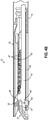
- FIG. 11 shows another exemplary instrument (310) configured as a surgical stapler.
- Instrument (310) comprises a handle portion (320) and a shaft (322).
- Instrument (310) has a modular configuration such that shaft (322) is selectively removable from, and attachable to, handle portion (320).
- Instrument (310) is configured similarly to instrument (10) such that the operability and use of instrument (310) is the same as described above for instrument (10) with the added feature of instrument (310) being a modular configuration.
- instrument (310) provides a way to change the end effector. Such a change in the end effector may be made to replace an otherwise worn end effector, or to provide for a different end effector configuration based on the procedure or user preference.
- features operable for providing the modular configuration of instrument (310) may be configured in accordance with at least some of the teachings of U.S. Pat. No. 10,182,813 , entitled “Surgical Stapling Instrument with Shaft Release, Powered Firing, and Powered Articulation,” issued January 22, 2019, the disclosure of which is incorporated by reference herein.
- Other suitable components, features, and configurations for providing instrument (310) with a modular configuration will be apparent to those of ordinary skill in the art in view of the teachings herein.
- instrument (10) may be modified to incorporate a modular configuration as shown and described with respect to instrument (310) or other instruments incorporated by reference herein.
- instrument (310) comprises an end effector (312) having an anvil (318) that has an angled distal tip (319). Furthermore, distal tip (319) of anvil (318) is elastically deformable. In this manner, and as shown best in FIGS. 12A and 12B , angled distal tip (319) is operable to elastically deform from a first angled position to a second position.
- the second position for angled distal tip (319) may be substantially straight in some versions, but may be angled to a degree (e.g., slightly above or slightly below the longitudinal axis (A1)) in other versions.
- the second position for angled distal tip (319) may be defined by the characteristics (e.g., thickness, density, etc.) of the tissue that is being captured between anvil (318) and lower jaw (16).
- end effector (312) is provided on shaft (322) that is detachable from handle portion (320).
- shaft (322) may be detachable from handle portion (320) in accordance with at least some of the teachings of U.S. Pat. No. 9,913,642 , entitled "Surgical Instrument Comprising a Sensor System," issued March 13, 2018, the disclosure of which is incorporated by reference herein. In some other versions, shaft (322) is not detachable from handle portion (320).
- end effector (312) may be used in place of end effector (12) shown in FIG. 1 .
- end effector (312) may be integrally formed with shaft (22) or alternatively may be separately formed and then combined.
- end effector (312) may be provided for use in robotic systems.
- modular shaft (322) having end effector (312) may be attachable to a portion of the robotic system for use such that handle portion (320) is replaced by components of the robotic system.
- end effector (312) may be adapted for use with a robotic system in a manner where end effector (312) connects with the robotic system without necessarily connecting the entire modular shaft (322).
- other ways to incorporate an end effector having an angled elastically deformable anvil tip into a user operated or robotic operated instrument will be apparent to those of ordinary skill in the art.
- FIG. 12A shows an enlarged side view of the distal end of end effector (312).
- End effector (312) comprises anvil (318) and lower jaw (16) that accepts cartridge (37) as described above with respect to instrument (10).
- Anvil (318) pivotably rotates toward lower jaw (16) in the same manner as anvil (18) as described above with respect to instrument (10).
- end effector (312) is similar to end effector (12), however, anvil (318) comprises angled distal tip (319) that is elastically deformable. As shown in FIG. 12A , tip (319) is imparted with a bias to an angled position that is shown in FIG. 11 and in phantom in FIG. 12A .
- Tip (319) assumes this angled position when end effector (312) is not clamping tissue and is open, as shown in FIG. 11 ; or closed without clamping tissue, as shown in phantom in FIG. 12A . In instances when end effector (312) is in this angled state or position, end effector (312) can be considered not loaded or in a non-loaded state or position. Conversely when end effector (312) is clamping tissue, end effector (312) can be considered loaded or in a loaded state or position.
- an underside surface (324) of tip (319) defines a plane that intersects a longitudinal axis (A1) defined by shaft (322) to form an angle ( ⁇ 1).
- underside surface (324) of tip (319) contacts tissue (90).
- underside surface (324) of tip (319) defines a plane that intersects longitudinal axis (A1) to form an angle ( ⁇ 2).
- angles ( ⁇ 1, ⁇ 2) are relative to longitudinal axis (A1), and the sum of angles ( ⁇ 1, ⁇ 2) represent the range of motion distal tip (319) undergoes.
- angle ( ⁇ 1) is between about 20 and about 70 degrees, or more particularly between about 30 degrees and about 50 degrees, in a downward direction from longitudinal axis (A1) toward cartridge (37).
- angle ( ⁇ 2) is between about 0 and about 90 degrees in an upward direction from longitudinal axis (A1) away from cartridge (37).
- the range of motion undergone by tip (319) is between about 20 degrees and about 110 degrees.
- the angles described for angles ( ⁇ 1, ⁇ 2) are exemplary only and not limiting. Other suitable angles will be apparent to those of ordinary skill in the art in view of the teachings herein.
- longitudinal axis (A1) represents a zero-degree reference and angles relative thereto may be positive or negative.
- the angle may be characterized as a negative angle.
- an angle is in an upward direction from longitudinal axis (A1) away from cartridge (37)
- the angle may be characterized as a positive angle.
- the range of motion of distal tip (319) due to deformation can be understood as the sum of the absolute value of the angle when distal tip (319) is in the position contacting cartridge (37), and the angle when distal tip (319) is in the deformed state when clamping tissue.
- FIG. 12B shows another side view of an alternate end effector (412) similar to end effector (312) of FIG. 12A .
- end effector (312) when anvil (318) is in its angled and non-deformed state (as seen in phantom in the view of FIG. 12A ), anvil (318) extends to a point even with or proximal to the distal most end of cartridge (37).
- anvil (318) is deformed such that it is deflected upwardly, the end of distal tip (319) extends to a point just distal to the distal most end of cartridge (37).
- anvil (318) when anvil (318) is in its angled and non-deformed state (as seen in phantom in the view of FIG. 12B ), anvil (318) extends to a point even with or proximal to the distal most end of cartridge (37).
- anvil (318) is deformed such that it is deflected upwardly, the end of a distal tip (319) of anvil (318) extends to a point even with or proximal to the distal most end of cartridge (37).
- anvil (318) of end effector (412) remains even with or proximal to the distal most end of cartridge (37) when anvil (318) is in its angled state or deformed state such that anvil (318) does not extend past the distal most end of cartridge (37) whether anvil (318) is in its angled and non-deformed state or in its deformed state. In some instances, this can be achieved by modifying anvil (318) such that distal tip (319) of anvil is shortened in length. In other instances, instruments (10, 310) may be modified to provide for a slight proximal retraction of anvil (318) when clamping. In view of the teachings herein, other ways to modify end effector (412) as it relates to control of anvil (318) position, will be apparent to those of ordinary skill in the art.
- tissue e.g., a large vessel
- angled and “bent” as used herein in connection with the various exemplary anvil tips disclosed encompass tip configurations in which the tip defines a flat planar exterior surface that extends angularly in a distal direction from the distal end of the anvil body; and also tip configurations in which the tip defines a curved exterior surface that extends arcuately in a distal direction from the distal end of the anvil body (e.g., where the tip is said to be in a "curved" configuration).
- a distal end of the anvil tip is vertically offset from a longitudinal axis of the anvil body along an axis that extends transversely to the longitudinal axis and through the corresponding staple cartridge, such that the tip as a whole is “angled” or "bent” relative to the anvil body.
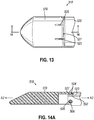
- FIGS. 13-16 depict exemplary anvils (518, 118) usable with the end effectors described herein and others.
- anvils (518, 118) can be interchanged or used in place of anvils (18, 218, 318) of respective end effectors (12, 212, 312, 412) described above.
- end effectors (12, 212, 312, 412) incorporating either of anvils (518, 118) may be used with instruments (10, 310) and the other surgical instruments described herein.
- end effectors (12, 212, 312, 412) incorporating either of anvils (518, 118) may be integrally formed with instruments (10, 310) and the other surgical instruments described herein, or in the alternative may be interchangeable end effectors of instruments (10, 310) and the other surgical instruments described herein.
- anvils (518, 118) are operable to pivot relative to lower jaws (16, 216).
- Anvils (518, 118) and lower jaws (16, 216) may clamp tissue (90) similarly to clamping performed by anvil (18) and lower jaw (16) shown in FIG. 7 .
- Anvils (518, 118) and lower jaws (16, 216) may further cut and staple clamped tissue (90) similarly to the cutting and stapling performed by anvil (18) and lower jaw (16) shown in FIG. 7 .
- end effectors (12, 212, 312, 412) incorporating either of anvils (518, 118) further comprises a cartridge (37, 237) containing staples where cartridge (37, 237) is operable to be placed in lower jaw (16, 216).
- Anvil (518) comprises a body (520) and a tip (519) extending distally from body (520). Proximal to tip (519), anvil (518) comprises an extension (502) on body (520). Anvil (518) further comprises a pair of spaced apart detents (504). A portion of detents (504) located on extension (502) are configured as raised portions or protrusions (510) as shown in the illustrated version. The other portion of detents (504) are located on tip (519) and are configured as recesses (523) as will be discussed further below. Anvil (518) also comprises a bore (506) that extends through the sides of body (520) of anvil (518) and bore (506) is configured to receive a pin (508). As will be discussed further below, pin (508) defines an axis of rotation about which tip (519) is rotatable.
- Tip (519) comprises a bore (521) that extends through the sides of tip (519) and bore (521) is configured to also receive pin (508). In this manner, tip (519) is operable to rotate about pin (508) and thus rotate relative to a longitudinal axis (A2) of anvil (518). Bores (506, 521) have a circular shape, but in other examples have an elongated shape. In some instances an elongated shape for bores (506, 521) provides for or contributes to tip (519) assuming different discrete positions as discussed further below. As mentioned above, tip (519) comprises a pair of recesses (523) that are configured to be selectively engageable with raised portions or protrusions (510) of detents (504).
- tip (519) At a proximal part of tip (519), tip (519) comprises a pair of slots (525) that extend longitudinally and define a resilient portion (527).
- resilient portion (527) comprises recesses (523) along an underside of resilient portion (527).
- anvil (518) is configured with tip (519) that can be moved into discrete positions.
- Detents (504) provide for selective engagement between raised portions (510) of detents (504) and recesses (523) of detents (504), which allow for tip (519) to move to different discrete positions.
- FIG. 14A illustrates tip (519) is a first position that has tip (519) in a straight orientation such that a longitudinal axis of tip (519) is generally parallel with or coincides with longitudinal axis (A2) of anvil (518).
- FIG. 15 illustrates tip (519) in a second position that has tip (519) in an angled orientation such that the longitudinal axis of tip (519) forms an angle with longitudinal axis (A2) of anvil (518) that is less than about 180 degrees.
- slots (525) define resilient portion (527), such that resilient portion (527) acts as a spring to thereby allow tip (519) to change positions by recesses (523) engaging raised portions (510) in different manners.
- resilient portion (527) acts as a spring to thereby allow tip (519) to change positions by recesses (523) engaging raised portions (510) in different manners.
- the proximal most recess (523) engages with the proximal most raised portion (510).
- the distal most recess (523) engages with the distal most raised portion (510).
- the proximal most recess (523) engages with the distal most raised portion (510).
- anvil (518) comprises a stop feature (500) that is configured to contact a proximal end of tip (519) and prevent tip (519) from moving to an even further angled position.
- tip (519) is adjustable or positionable in discrete positions rather than having a continuum of orientations.
- tip (519) is configured to adopt discrete positions where tip (519) remains in one of the discrete positions until acted upon by a force sufficient to overcome the interference connection established between recesses (523) and raised portions (510) of detents (504).
- a gap (529) can be present in some versions.
- An optional sleeve (not shown) can be added to anvil (518) to cover or extend over gap (529) to remove the possibility that gap (529) could present a pinch point for surrounding tissue.
- such a sleeve could extend to reach the end of tip (519) and go as far back as the stapling line of anvil (518), although this would not be required in all versions.
- anvil (518) is constructed of a single material such as stainless steel, but other materials instead of stainless steel can be used in other versions. Furthermore, in some other versions, anvil (518) can be overcoated with another material to provide for visualization, sliding, or other material properties or attributes as will be apparent to those of ordinary skill in the art in view of the teachings herein.
- three detents (504) can be used such that three discrete positions for tip (519) can be defined.
- tip (519) can be configured to adopt either a straight orientation, an angled orientation (which may form a curved configuration), or a flared or open orientation where tip (519) is bent upward away from lower jaw (16, 216).
- detents (504) can be located on the sides of tip (519) and body (520) of anvil (518) instead of the top. Still yet, in some other examples, the location of the features of detents (504) can be opposite.
- FIG. 16 illustrates another exemplary anvil (118) usable with the end effectors described herein and others.
- Anvil (118) is similar to anvil (518) described above except for the differences noted below. Thus, the description above for anvil (518) applies equally to anvil (118).
- Anvil (118) comprises a body (520) and a tip (119) extending distally from body (520).
- the features and functions of anvil (518) apply equally to anvil (118) including the features and functions of tip (519) applying equally to tip (119).
- tip (119) includes additional features and functionality.
- tip (119) comprises a distal portion (131) and a proximal portion (133).
- tip (119) is configured such that not only is proximal portion (133) rotatable to discrete positions relative to body (520) of anvil (118) as described above with respect to anvil (118), but distal portion (131) is rotatable to discrete positions relative to proximal portion (133) of tip (119).
- rotatability of distal portion (131) relative to proximal portion (133) occurs in the same manner as the rotatability of proximal portion (133) relative to body (520) of anvil (118).
- a pin (135) extends through and connects distal portion (131) and proximal portion (133).
- pin (135) provides and defines an axis of rotation about which distal portion (131) may rotate.
- tip (119) is comprised of multiple pinned pieces or sections. This configuration allows for a greater angle and also in some versions an overall curvature-like shape to be achieved with otherwise straight but angled sections of tip (119).
- a first discrete position for distal portion (131) is a straight orientation relative to proximal portion (133) as shown in FIG. 16 .
- a second discrete position for distal portion (131) is an angled or curved orientation relative to proximal portion (133) where distal portion (131) bends or angles downward toward lower jaw (16, 216) of the associated end effector.
- the second discrete position for distal portion (131) could be flared or bent upward relative to proximal portion (133).
- other configurations and ways to achieve such configurations for a tip (119) having multiple rotatable pinned sections will be apparent to those of ordinary skill in the art.
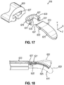
- FIGS. 17 and 18 depict a portion of an exemplary anvil (618) that is usable with the end effectors described herein and others.
- anvil (618) can be interchanged or used in place of anvils (18, 218, 318) of respective end effectors (12, 212, 312, 412) described above.
- end effectors (12, 212, 312, 412) incorporating anvil (618) may be used with instruments (10, 310) and the other surgical instruments described herein.
- end effectors (12, 212, 312, 412) incorporating anvil (618) may be integrally formed with instruments (10, 310) and the other surgical instruments described herein, or in the alternative may be interchangeable end effectors of instruments (10, 310) and the other surgical instruments described herein.
- anvil (618) is operable to pivot relative to lower jaws (16, 216).
- Anvil (618) and lower jaws (16, 216) may clamp tissue (90) similarly to clamping performed by anvil (18) and lower jaw (16) shown in FIG. 7 .
- Anvil (618) and lower jaws (16, 216) may further cut and staple clamped tissue (90) similarly to the cutting and stapling performed by anvil (18) and lower jaw (16) shown in FIG. 7 .
- end effectors (12, 212, 312, 412) incorporating anvil (618) further comprises a cartridge (37, 237) containing staples where cartridge (37, 237) is operable to be placed in lower jaw (16, 216).
- Anvil (618) comprises body (620), tip (619), and connection member (621).
- Tip (619) comprises a polymeric or metallic covering (shown as an elastomeric overmold (623)) and a pivot member (625) as best seen in FIG. 18 .
- Connection member (621) is configured to attach with body (620).
- connection member (621) comprises a metal stamping configured to be welded to body (620) of anvil (618).
- connection member (621) is configured to be press-fit or clicked to body (620).
- connection member (621) may comprise features that engage with slot (627) of body (620).
- other ways to attach connection member (621) with body (620) of anvil (618) will be apparent to those of ordinary skill in the art.
- Connection member (621) comprises arms (629) that extend distally. Arms (629) each comprise bores (631) that are configured to receive projections (633) of pivot member (625). In this manner, bores (631) provides a pivot axis or axis of rotation for tip (619). Connection member (621) further comprises a curved lip (635) that acts like a fulcrum feature. Curved lip (635) protrudes distally and is configured to interact with a proximal end (637) of pivot member (625) of tip (619).
- Pivot member (625) is connectable with connection member (621) as mentioned, with projections (633) being received within bores (631) of connection member (621). With this configuration, pivot member (625) is rotatably adjustable relative to connection member (621) and body (620) of anvil (618). When projections (633) are within bores (631), proximal end (637) of pivot member (625) is located in a slight overlapping orientation relative to curved lip (635). The remainder of pivot member (625) extends distally from connection member (621). As shown in FIG. 18 , elastomeric overmold (623), shown in phantom to reveal internal components, covers pivot member (625) and connection member (621).
- tip (619) is configured to rotate or pivot about the pivot axis defined by bores (631), whereby proximal end (637) of pivot member (625) can adopt discrete positions relative to curved lip (635), such that tip (619) adopts discrete positions relative body (620).
- proximal end (637) of pivot member (625) in a first position, can have an angled orientation. In the illustrated version, this corresponds to when proximal end (637) of pivot member (625) is above curved lip (635).
- pivot member (625) in a second position, pivot member (625) can have a straight or slightly flared orientation. In the illustrated version, this corresponds to when proximal end (637) of pivot member (625) is below curved lip (635).
- elastomeric overmold (623) acts as the spring that holds pivot member (625) in place on either side of curved lip (635) until a sufficient force is applied to tip (619) to overcome the bias provided by elastomeric overmold (623) and the contact between proximal end (637) and curved lip (635).
- proximal end (637) of pivot member (625) will rotate downward and click past curved lip (635) allowing tip (619) to adopt the other discrete position.
- proximal end (637) of pivot member (625) will rotate upward and click past curved lip (635) allowing tip (619) to adopt the other discrete position.
- proximal end (637) is rounded and toleranced so that it clicks past curved lip (635), which acts as the fulcrum feature.
- curved lip (635) can incorporate a rounded and toleranced distal end to facilitate movement of proximal end (637) from one side of curved lip (635) to the other side of curved lip (635).
- tip (619) will remain in place because of elastomeric overmold (623) acting as the spring to hold pivot member (625) in place.
- tuning for force or sound feedback could be accomplished by configuring the fulcrum feature with a deformable dome-type geometry that proximal end (637) moves past when changing discrete positions.
- proximal end 637
- greater or lesser deformation can be used with the fulcrum feature so that a user gets haptic and/or audible feedback confirming tip (619) has changed position.
- other ways to modify anvil (618), connection member (621), and tip (619) to achieve a pivoting tip that adopts discrete positions will be apparent to those of ordinary skill in the art.
- FIGS. 19 and 20 depict a portion of an exemplary anvil (718) that is usable with the end effectors described herein and others.
- anvil (718) can be interchanged or used in place of anvils (18, 218, 318) of respective end effectors (12, 212, 312, 412) described above.
- end effectors (12, 212, 312, 412) incorporating anvil (718) may be used with instruments (10, 310) and the other surgical instruments described herein.
- end effectors (12, 212, 312, 412) incorporating anvil (718) may be integrally formed with instruments (10, 310) and the other surgical instruments described herein, or in the alternative may be interchangeable end effectors of instruments (10, 310) and the other surgical instruments described herein.
- anvil (718) is operable to pivot relative to lower jaws (16, 216).
- Anvil (718) and lower jaws (16, 216) may clamp tissue (90) similarly to clamping performed by anvil (18) and lower jaw (16) shown in FIG. 7 .
- Anvil (718) and lower jaws (16, 216) may further cut and staple clamped tissue (90) similarly to the cutting and stapling performed by anvil (18) and lower jaw (16) shown in FIG. 7 .
- end effectors (12, 212, 312, 412) incorporating anvil (718) further comprises a cartridge (37, 237) containing staples where cartridge (37, 237) is operable to be placed in lower jaw (16, 216).
- Anvil (718) comprises body (720), tip (719), and connection member (721).
- Tip (719) comprises a polymeric or metallic covering (shown as an elastomeric overmold (723)) and a pivot member (725).
- Connection member (721) is configured to attach with body (720).
- connection member (721) comprises a metal stamping configured to be welded to body (720) of anvil (718).
- connection member (721) is configured to be press-fit or clicked to body (720).
- connection member (721) may comprise features that engage with a slot of body (720), similar to slot (627) of body (620).
- Connection member (721) comprises a dual bump feature (735) that extends distally. As shown in the illustrated version, connection member (721) further comprises a space or gap (739) between the bumps of dual bump feature (735). In the present example, but not required in all versions, dual bump feature (735) is rigid. Pivot member (725) comprises triangular body (741) and elongated member (743) connected with and extending distally from triangular body (741). In the present example, but not required in all versions, pivot member (725) comprises a metallic structure.
- dual bump feature (735) is dimensioned and toleranced to interact with triangular body (741) of pivot member (725).
- dual bump feature (735) defines base corners (745, 747), and triangular body (741) defines vertexes (749, 751).
- vertex (749) is biased into base corner (745).
- vertex (751) is pivoted away from base corner (747) and is instead near a distal end of dual bump feature (735). As shown in FIG.
- vertex (751) is biased into base corner (747).
- vertex (749) is pivoted away from base corner (745) and is near a distal end of dual bump feature (735).
- elastomeric overmold (723) biases triangular body (741) proximally.
- elastomeric overmold (723) acts as the spring that holds triangular body (741) of pivot member (725) in place against dual bump feature (735).
- triangular body (741) pivots between dual bump feature (735) as illustrated by the change in position of triangular body (741) in FIGS. 19 and 20 .
- FIG. 19 For instance, when in the angled or curved orientation, shown in FIG.
- vertex (749) of triangular body (741) travels distally along a lower bump of dual bump feature (735).
- vertex (751) of triangular body (741) of pivot member (725) travels proximally along an upper bump of dual bump feature (735) until locking into base corner (747).
- vertex (749) of triangular body (741) travels proximally along a lower bump of dual bump feature (735) until locking into base corner (745).
- vertex (751) of triangular body (741) of pivot member (725) travels distally along an upper bump of dual bump feature (735).
- toggling the position of tip (719) may involve a user pinching and pulling distally on tip (719) thereby temporarily deforming elastomeric overmold (723) when relocating tip (719).
- toggling the position of tip (719) may involve a user pushing upward or downward such that the force is largely orthogonally applied to the longitudinal axis of anvil (718).
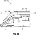
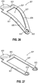
- FIGS. 21-29 and FIGS. 30-32 depict exemplary end effectors (812, 912) with respective anvils (818, 918).
- End effectors (812, 912) can be interchanged or used in place of end effectors (12, 212, 312, 412) described above. It will be appreciated that end effectors (812, 912) may be used with instruments (10, 310) and the other surgical instruments described herein. To this extent, end effectors (812, 912) with respective anvils (818, 918) may be integrally formed with instruments (10, 310) and the other surgical instruments described herein, or in the alternative may be interchangeable end effectors of instruments (10, 310) and the other surgical instruments described herein.
- End effectors (812, 912) are operable to clamp tissue (90) similarly to clamping performed by end effector (12) shown in FIG. 7 .
- End effectors (812, 912) are further operable to cut and staple clamped tissue (90) similarly to the cutting and stapling performed by end effector (12) shown in FIG. 7 .
- FIGS. 21-23 illustrate an exemplary end effector (812) comprising anvil (818), lower jaw (16), and staple cartridge (37) positioned within lower jaw (16).
- Lower jaw (16) and cartridge (37) are described above with respect to other end effectors and those descriptions apply equally here to end effector (812).
- Anvil (818) comprises a tip (819).
- Tip (819) includes a deformable member that is flexible, such that tip (819) is movable relative to anvil (818) between a first discrete position and a second discrete position using the deformable member. For instance, the first discrete position is illustrated in FIGS.
- tip (819) has an angled or curved orientation relative to a longitudinal axis (A3) of anvil (818) until the deformable member is acted upon by an external input force.
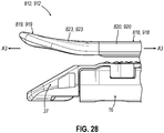
- the second discrete position is illustrated in FIG. 23 where tip (819) has a straight orientation relative to longitudinal axis (A3) until the deformable member is acted upon by an external input force.
- tip (819) With the straight orientation, tip (819) is generally aligned with the remainder of anvil (818), and tip (819) extends parallel to longitudinal axis (A3).
- tip (819) is angled relative to longitudinal axis (A3) such that tip (819) extends towards lower jaw (16) and cartridge (37).
- the angled orientation may form a curved orientation.
- a user may select a desired discrete position for tip (819). This may be done, for example, when reloading a new cartridge (37) onto end effector (812).
- the user may select the angled orientation for tip (819) when the user is trying to position and navigate anvil (818) around tissue such as a vessels and other tubular structures.
- the user may select the straight orientation for tip (819) when the user is trying to get over tissue as the straight orientation for tip (819) gives a larger aperture compared to the angled orientation for tip (819).
- the user may also select the straight orientation for tip (819) when the user is performing a procedure involving marching as described above.
- the deformable member may include a polymeric or metallic covering and an internal support structure.
- FIG. 24 illustrates an enlarged perspective view of a distal end of end effector (812), where a polymeric or metallic covering (shown as an elastomeric overmold (823)) of tip (819) is shown transparently to reveal internal components of tip (819).
- Deformable member of tip (819) may include an internal support structure (shown as an internal clip (821) in FIG. 24 ) so that tip (819) remains in the desired discrete position until acted upon by an external input force. While internal clip (821) shows one such suitable support structure, other support structures having various shapes and sizes are also envisioned.
- internal clip (821) connects with and extends distally from a body (820) of anvil (818).
- Internal clip (821) comprises a base (825) and a pair of arms (827) extending distally from base (825). Arms (827) converge as they extend distally, and arms (827) are joined at their respective distal end by a rivet (829) as shown in the present example.
- Internal clip (821) further comprises a space (831) between arms (827), and in the present example, space (831) has a triangular shape.
- Internal clip (821) is configured as an over-center snap clip having two discrete positions that correspond to the angled orientation and straight orientation of tip (819) as described above. Furthermore, internal clip (821) may be overmolded with an elastomeric material such that tip (819) comprises elastomeric overmold (823) as mentioned above. Still in some other versions, internal clip (821) may be inserted within an otherwise formed flexible tip such that it is not required that internal clip (821) be overmolded to be surrounded by elastomeric material.
- FIG. 25 illustrates tip (819) in the straight orientation and showing the elastomeric overmold (823) as transparent to reveal internal clip (821) in this state or position.
- internal clip (821) when applying a sufficient downward force from a top side of tip (819), internal clip (821) will snap into its angled (e.g. bent or curved) orientation associated with the first discrete position as described above. In this manner, internal clip (821) is deflectable and comprises a bias to assume either a first position associated with an angled orientation for tip (819), or a second discrete position associated with a straight orientation for tip (819).
- FIGS. 26 and 27 illustrate internal clip (821) and further features thereof.
- rivet (829) is omitted from FIGS. 26 and 27 , revealing that arms (827) each comprise a bore (833) at their distal ends. Bores (833) are each configured and sized to receive rivet (829) and thereby join arms (827).
- FIG. 26 shows internal clip (821) in its assembled or shaped form where arms (827) have been forced toward one another to align bores (833) of each to ultimately receive rivet (829).
- FIG. 27 shows internal clip (821) in its unassembled or stamped form where arms (827) do not converge and bores (833) do not align.
- internal clip (821) comprises a stamped metal structure. However, in other examples, other materials besides metal may be used to construct internal clip (821).
- a proximal extension (835) of internal clip (821) is configured to be received by and connected to body (820) of anvil (818). In this manner, internal clip (821) is secured to anvil (818). In some versions, internal clip (821) may be welded to body (820) of anvil (818), for instance, welding proximal extension (835) to body (820). In view of the teachings herein, various other ways to connect internal clip (821) with anvil (818) will be apparent to those of ordinary skill in the art.
- FIGS. 28 and 29 depict another version of end effector (812) where internal clip (821) is configured with a bias to assume either a first discrete position associated with a curved orientation for tip (819) as shown and described above with respect to FIGS. 21 , 22 , and 24 , or to assume a second discrete position associated with a flared orientation for tip (819) as shown in FIGS. 28 and 29 .
- a flared orientation may also be referred to as a crowned orientation.
- tip (819) is angled upward relative to longitudinal axis (A3) of anvil (818).
- a flared orientation provides for an even greater aperture, which may be useful when trying to get over tissue, and/or when conducting procedures involving marching.
- end effector (812) as shown in FIGS. 28 and 29 are the same as that shown and described above with respect to FIGS. 21-27 .
- the geometry and material of both elastomeric overmold (823) and/or internal clip (821) may contribute to the discrete positions of tip (819). For instance, in one example, a change to a more flexible elastomer for elastomeric overmold (823) may permit internal clip (821) to change positions to a greater extent. In one version, this is a way to change the configuration of tip (819) from having angled and straight orientations to instead having angled and flared orientations. In another example, internal clip (821) may be made stiffer by increasing its mass, altering its material, or altering the geometry of internal clip (821).
- tip (819) may be configured to provide angled, straight, and flared orientations, and thus, tip (819) would have three discrete positions available to the user.
- various other ways to configure the components of tip (819) to achieve the desired discrete positions for tip (819) will be apparent to those of ordinary skill in the art.
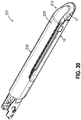
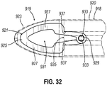
- FIGS. 30-32 illustrate an exemplary end effector (912) comprising anvil (918), lower jaw (16), and staple cartridge (37) positioned within lower jaw (16).
- Lower jaw (16) and cartridge (37) are described above with respect to other end effectors and those descriptions apply equally here to end effector (912).
- Anvil (918) comprises a tip (919).
- Tip (919) includes a deformable member that is flexible, such that tip (919) is movable relative to anvil (918) between a first discrete position and a second discrete position using the deformable member. For instance, the first discrete position is illustrated in FIGS.
- tip (919) has a angled (e.g., curved) or bent orientation relative to a longitudinal axis (A3) of anvil (918) until the deformable member is acted upon by an external input force.
- the second discrete position is illustrated in FIG. 23 where tip (919) has a straight orientation relative to longitudinal axis (A3) until the deformable member is acted upon by an external input force.
- tip (919) With the straight orientation, tip (919) is generally aligned with the remainder of anvil (918), and tip (919) extends parallel to longitudinal axis (A3).
- tip (919) is angled relative to longitudinal axis (A3) such that tip (919) extends towards lower jaw (16) and cartridge (37).
- the angled orientation may form a curved orientation, as described above.
- a user may select a desired discrete position for tip (919). This may be done, for example, when reloading a new cartridge (37) onto end effector (912).
- the user may select the angled orientation for tip (919) when the user is trying to position and navigate anvil (918) around tissue such as a vessels and other tubular structures.
- the user may select the straight orientation for tip (919) when the user is trying to get over tissue as the straight orientation for tip (919) gives a larger aperture compared to the angled orientation for tip (919).
- the user may also select the straight orientation for tip (919) when the user is performing a procedure involving marching as described above.
- Deformable member may include a polymeric or metallic covering and an internal support structure.
- FIG. 31 illustrates an enlarged perspective view of a distal end of anvil (918) of end effector (912), where the polymeric or metallic covering (shown as an elastomeric overmold (923)) of tip (919) and body (920) of anvil (918) are shown transparently to reveal internal components.
- Deformable member of tip (919) may comprise an internal support structure (shown as internal clip (921)) that connects with and extends distally from a body (920) of anvil (918).
- Internal clip (921) comprises an apex portion (925) and a pair of arms (927) extending proximally from apex portion (925).
- Arms (927) initially diverge as they extend proximally, and then converge as they approach their respective proximal ends. Arms (927) are joined at their respective proximal ends by a pin (929) within body (920) of anvil (918) that extends through respective aligned bores (933) of arms (927) as shown in the present example.
- pin (929) may be replaced by a rivet or by a spiral pin.
- Internal clip (921) further comprises a space (931) between arms (927), and in the present example, space (931) has a triangular shape.
- Internal clip (921) is configured as an over-center snap clip having two discrete positions that correspond to the angled orientation and straight orientation of tip (919) as described above. Furthermore, internal clip (921) may be overmolded with an elastomeric material such that tip (919) comprises elastomeric overmold (923) as mentioned above. Still in some other versions, internal clip (921) may be inserted within an otherwise formed flexible tip such that it is not required that internal clip (921) be overmolded to be surrounded by elastomeric material.
- end effector (912) having anvil (918) and tip (919), to toggle or switch the discrete position of tip (919)
- a user would apply a force to tip (919) in the direction the user wanted tip (919) to move. For instance, where tip (919) is in the first position with the angled orientation as shown in FIG. 30 , by opening end effector (912) and applying an upward force from an underside of tip (919), internal clip (921) will snap into its straight orientation associated with the second discrete position as described above. Similarly, where tip (919) is in the second discrete position with a straight orientation as shown in FIG.
- internal clip (921) when applying a sufficient downward force from a top side of tip (919), internal clip (921) will snap into its curved or bent orientation associated with the first discrete position as described above. In this manner, internal clip (921) is deflectable and comprises a bias to assume either a first position associated with an angled orientation for tip (919), or a second discrete position associated with a straight orientation for tip (919).
- FIG 32 illustrates a top view of internal clip (921) and further features thereof.
- pin (929) extends orthogonally relative to the longitudinal axis of body (920) of anvil (918).
- Arms (927) are positioned to align bores (933) such that bores (933) are each configured and sized to receive pin (929) and thereby join arms (927).
- internal clip (921) is in its assembled or shaped form where arms (927) have been forced toward one another to align bores (933) of each to ultimately receive pin (929). Similar to internal clip (821) described above, internal clip (921) also has an unassembled or stamped form where arms (927) do not converge and bores (933) do not initially align.
- internal clip (921) comprises a stamped metal structure.
- other materials besides metal may be used to construct internal clip (921).
- various other ways to connect internal clip (921) with anvil (918) will be apparent to those of ordinary skill in the art.
- FIG. 28 depicts another version of end effector (912) where internal clip (921) is configured with a bias to assume either a first discrete position associated with a curved orientation for tip (919) as shown and described above with respect to FIG. 30 , or to assume a second discrete position associated with a flared orientation for tip (919) as shown in FIG. 28 .
- a flared orientation may also be referred to as a crowned orientation.
- tip (919) is angled upward relative to longitudinal axis (A3) of anvil (918).
- A3 longitudinal axis
- a flared orientation provides for even greater aperture, which may be useful when trying to get over tissue, and/or when conducting procedures involving marching.
- the remaining features and functions of end effector (912) as shown in FIGS. 28 are the same as that shown and described above with respect to FIGS. 30-32 .
- both elastomeric overmold (923) and/or internal clip (921) geometry and material can contribute to the discrete positions that tip (919) will adopt.
- a change to a more flexible elastomer for elastomeric overmold (923) can permit internal clip (921) to change positions to a greater extent.
- this is a way to change the configuration of tip (919) from having curved and straight orientations to instead having curved and flared orientations.
- internal clip (921) may be made stiffer by increasing its mass, altering its material, and/or altering its geometry.
- tip (919) may be configured to provide curved, straight, and flared orientations and thus tip (919) would have three discrete positions available to the user.
- various other ways to configure the components of tip (919) to achieve the desired discrete positions for tip (919) will be apparent to those of ordinary skill in the art.
- tip (919) Another consideration with tip (919) in terms of configuring the discrete positions relates to the proximal portions of arms (927) that ultimately engage with pin (929). More specifically, the degree of the freedom of movement of the proximal portions of arms (927) with respect to the pin (929) influence the positions that internal clip (921) will adopt when changing from a first discrete position to a second discrete position. For instance, when internal clip (921) snaps from one discrete position to another discrete position, bores (933) of arms (927) can travel along pin (929) to some extent.
- a larger travel length of bores (933) of arms (927) along pin (929) equates to a larger difference in position from the first discrete position to the second discrete position when internal clip (921) snaps from one to the other.
- body (920) can be configured to allow greater or lesser freedom of movement of bores (933) along pin (929) depending on the space available for bores (933) to travel along pin (929).
- having the connection of arms (927) within body (920) of anvil (918), instead of within elastomeric overmold (923) can promote greater freedom of movement of arms (927) along pin (929).
- the diameter of pin (929) can influence the friction between pin (929) and bores (933) and thus freedom of movement of arms (927) relative to pin (929).
- anvil (918) comprises slot (935) within body (920) where slot (935) is defined as the space between two walls (937) extending within body (920). As shown, the proximal portion of arms (927) are moved close enough to one another to fit within slot (935) and ultimately connect with pin (929). With this configuration, the dimensions of slot (935) defined by walls (937) acts to limit the lateral movement ability of arms (927).
- This limited lateral movement impacts the degree of change in position when internal clip (921) snaps from its first discrete position to its second discrete position.
- altering the width of slot (935) can provide another way to control the range of motion of internal clip (921).
- the height of slot (935) can influence the range of motion arms (927) have to travel along pin (929). For instance, a small height may be more restrictive and thereby impede arms (927) from traveling along pin (929) when tip (919) moves from the first discrete position to the second discrete position. Similarly, a larger height may be less restrictive and allow arms (927) to travel further along pin (929) when tip (919) is toggled.
- FIGS. 33-35 depict an exemplary anvil (1018) that is usable with the end effectors described herein and others.
- anvil (1018) can be interchanged or used in place of anvils (18, 218, 318) of respective end effectors (12, 212, 312, 412) described above.
- end effectors (12, 212, 312, 412) incorporating anvil (1018) may be used with instruments (10, 310) and the other surgical instruments described herein.
- end effectors (12, 212, 312, 412) incorporating anvil (1018) may be integrally formed with instruments (10, 310) and the other surgical instruments described herein, or in the alternative may be interchangeable end effectors of instruments (10, 310) and the other surgical instruments described herein.
- anvil (1018) is operable to pivot relative to lower jaws (16, 216).
- Anvil (618) and lower jaws (16, 216) may clamp tissue (90) similarly to clamping performed by anvil (18) and lower jaw (16) shown in FIG. 7 .
- Anvil (1018) and lower jaws (16, 216) may further cut and staple clamped tissue (90) similarly to the cutting and stapling performed by anvil (18) and lower jaw (16) shown in FIG. 7 .
- end effectors (12, 212, 312, 412) incorporating anvil (1018) further comprises a cartridge (37, 237) containing staples where cartridge (37, 237) is operable to be placed in lower jaw (16, 216).
- anvil (1018) comprises body (1020) and tip (1019).
- Tip (1019) connects with and extends distally from body (1020).
- Tip (1019) comprises a support structure (shown as internal clip (1021) in phantom), and a polymeric or metallic covering (shown as an elastomeric overmold (1023)).
- tip (1019) is configured such that internal clip (1021) can be toggled from a first discrete position having an angled orientation as shown in FIG. 34 , to a second discrete position having a straight orientation as shown in FIG. 35 by applying an external input force.
- Internal clip (1021) comprises arms (1027) and a space (1031) between arms (1027). Furthermore, elastomeric overmold (1023) comprises an opening (1033) extending though tip (1019). Opening (1033) aligns with space (1031) of internal clip (1021). By altering the size and shape of opening (1033) as well as space (1031), the deflection of tip (1019) to discrete positions can be controlled to achieve desired curved and straight or flared orientations. In view of the teachings herein, other ways to control the discrete positions of internal clip (1021) will be apparent to those of ordinary skill in the art.
- FIG. 36 illustrates a plurality of alternate internal clips (1121), each internal clip (1121) being usable within a tip of an anvil of an end effector for use with the surgical instruments described herein.
- internal clips (1121) may be used in place of internal clips (821, 921, 1021).
- Internal clips (1121) comprise a resilient middle rib (1122) that extends longitudinally between a pair of arms (1127) of internal clip (1121).
- Middle rib (1122) is deflectable and comprises a bias to adopt discrete positions.
- internal clip (1121) is configured as a barrette style clip.
- internal clip (1121) replaces internal clip (821, 921, 1021)
- internal clip (1121) may be overmolded with an elastomeric overmold as described above. Additionally, in view of the teachings herein various ways to control the discrete positions of internal clip (1121) to thereby control discrete positions of a tip using internal clip (1121) will be apparent to those of ordinary skill in the art.
- the elastomeric overmold works in conjunction with certain internal clips and pivot members as a system or assembly to provide for multiple discrete tip positions.
- the tip can be toggled or adjusted between these discrete positions by applying an external force, i.e., by the user, the user's hand tool, a robotic manipulator, or the patient's anatomy.
- modifications to the various configurations and designs of the elastomeric overmold can impact the ease or difficulty of moving or toggling a tip from one discrete position to another.
- one example of this involves using elastomers of varying stiffness.
- another example of this mentioned above involves changing the elastomer mass and/or geometry, e.g., by including an opening such as opening (1033) described above.
- the tips described herein include elastomeric overmolds, the overmold may surround all structures of the tip, and may bond to all structures of the tip.
- the overmold is configured to not surround and/or bond to all structures of the tip.
- tips having elastomeric overmolds described herein which include at least tips (219, 319, 619, 719, 819, 919, 1019) and at least elastomeric overmolds (623, 723, 823, 923, 1023).
- elastomeric overmold (623, 723, 823, 923, 1023) of tip (219, 319, 619, 719, 819, 919, 1019) is bonded directly to anvil (218, 318, 618, 718, 818, 918, 1018), or directly to an intermediate connector such as connection member (621, 721) so that it forms a contiguous smooth surface, free of openings or gaps when the tip is deformed.
- bonding to certain locations allows the elastomer to be have a spring bias and act as a spring and thus source of the tension that could aid in providing the tip with discrete positions.
- elastomeric overmold (623, 723, 823, 923, 1023) of tip (219, 319, 619, 719, 819, 919, 1019) can be specifically blocked from being bonded to certain locations.
- bonding of elastomeric overmold (623, 723, 823, 923, 1023) is partially or completely blocked such that pivot member (625, 725) or internal clip (821, 921, 1021, 1121) is not bonded to elastomeric overmold (623, 723, 823, 923, 1023).
- the dynamics of the toggle can be varied by allowing relative slip between pivot member (625, 725) or internal clip (821, 921, 1021, 1121), and elastomeric overmold (623, 723, 823, 923, 1023).
- pivot member (625, 725) or internal clip (821, 921, 1021, 1121) in wax or another coating, so that the elastomer does not bond to it, thereby allowing relative slip.
- pivot member (625) comprises coating (628), and internal clip (821) comprises coating (828).
- coatings (628, 828) comprise a wax, but other coating materials may be used.
- coatings (628, 828) can be applied to the entirety of pivot member (625) and internal clip (821) in some versions. However, in other versions coating (628, 828) can be applied to portions of pivot member (625) and internal clip (821). For instance, with respect to internal clip (821), in one example coating (828) is applied to pair of arms (827) only. Still yet, coatings (628, 828) are omitted entirely in other examples of pivot member (625) and internal clip (821). In view of the teachings herein, other ways to block bonding of the elastomeric overmold to certain structures of the tip will be apparent to those of ordinary skill in the art.
- a base or proximal portion of tip (619, 719, 819, 919, 1019) is covered, while the raw or partially raw pivot member (625, 725) or internal clip (821, 921, 1021, 1121) extends distally.
- internal clips (821, 921, 1021, 1121) With respect to internal clips (821, 921, 1021, 1121), in one example such internal clips (821, 921, 1021, 1121) are described as configured with a barrette design so that internal clips (821, 921, 1021, 1121) contain elastic energy after they are riveted. In this manner internal clips (821, 921, 1021, 1121) can have stored elastic energy.
- an external force is applied.
- this external force may be applied by the user, the user's hand tool, a robotic manipulator, or the patient's anatomy.
- the arms of internal clips (821, 921, 1021, 1121) undergo elastic deformation and reactive force builds until it reaches a state instability.
- internal clips (821, 921, 1021, 1121) will pass over or through the instability zone to another lower energy state.
- internal clips (821, 921, 1021, 1121) are comprised with bistability in some cases, and even multi-stability in other cases.
- bistability internal clips (821, 921, 1021, 1121) comprise two positions with low energy states where internal clips (821, 921, 1021, 1121) will maintain their shape and position absent an external force being applied thereto.
- internal clips (821, 921, 1021, 1121) comprises more than two positions with low energy states where internal clips (821, 921, 1021, 1121) will maintain their shape and position absent an external force being applied thereto.
- internal clips (821, 921, 1021, 1121) can be described as comprising the ability to twist, bend, or buckle from one state or position to another.
- various ways to modify and control the stability and positioning of internal clips (821, 921, 1021, 1121) will be apparent to those of ordinary skill in the art.
- An apparatus comprising: (a) a body; (b) a shaft extending from the body, wherein the shaft defines a longitudinal axis; and (c) an end effector in communication with the shaft, wherein the end effector is operable to compress, staple, and cut tissue, wherein the end effector comprises: (i) a first jaw configured to retain a cartridge configured to hold one or more staples, (ii) a second jaw comprising an anvil, wherein at least one of the first jaw or the second jaw is configured to move relative to the other of the first jaw or the second jaw between an open position and a closed position, and (iii) a tip connected with the anvil, wherein the tip comprises a deformable member, wherein the tip is movable relative to the anvil between a first discrete position and a second discrete position using the deformable member, wherein the tip remains in the first discrete position that is located closer toward the cartridge until the deformable member is acted upon by an external input force, and wherein the tip remains in the
- Example 1 The apparatus of Example 1, wherein in the first discrete position the tip comprises an angled orientation relative to a longitudinal axis of the anvil, and wherein in the second discrete position the tip comprises a straight orientation relative to a longitudinal axis of the anvil.
- Example 1 The apparatus of Example 1, wherein in the first discrete position the tip comprises an angled orientation relative to a longitudinal axis of the anvil, and wherein in the second discrete position the tip comprises a flared orientation relative to the longitudinal axis of the anvil.
- Example 3 The apparatus of any one or more of Example 1 through Example 3, wherein the deformable member comprises a polymeric cover and an internal support structure.
- Example 4 The apparatus of Example 4, wherein the internal support structure comprises an internal clip.
- Example 4 wherein the internal clip is deflectable and comprises a bias to assume a select one of a first orientation and a second orientation, and wherein the internal clip comprises a pair of arms that converge and are joined at respective distal or proximal ends.
- Example 6 The apparatus of Example 6, wherein the pair of arms are joined at their respective distal or proximal ends by a rivet or by a pin extending within the anvil.
- Example 7 The apparatus of any one or more of Example 6 through Example 7, wherein the internal clip comprises a space between the pair of arms.
- Example 8 The apparatus of any one or more of Example 6 through Example 8, wherein the internal clip further comprises a resilient middle rib extending longitudinally between the pair of arms, wherein the middle rib is deflectable and comprises a bias to assume two or more discrete positions.
- Example 4 The apparatus of any one or more of Example 4 through Example 9, wherein the polymeric cover comprises an elastomeric overmold.
- Example 10 wherein the elastomeric overmold comprises an opening extending through the tip, wherein the opening aligns with the space of the internal clip between the pair of arms.
- Example 4 The apparatus of any one or more of Example 4 through Example 9, wherein the elastomeric overmold is bonded to the anvil and the internal clip or the elastomeric overmold is bonded to the anvil and at least partially blocked from bonding to the internal clip.
- Example 10 The apparatus of any one or more of Example 10 through Example 12, wherein the internal clip comprises a coating configured to block the elastomeric overmold from bonding to the internal clip where the coating is placed.
- Example 13 The apparatus of Example 13, wherein the coating comprises a wax.
- Example 10 The apparatus of any one or more of Example 10 through Example 13, wherein the internal clip is partially exposed at a distal end such that the elastomeric overmold does not cover the entirety of the internal clip.
- Example 5 The apparatus of any one or more of Example 5 through Example 15, wherein the internal clip comprises a bistability configuration.
- Example 5 The apparatus of any one or more of Example 5 through Example 15, wherein the internal clip comprises a multi-stability configuration.
- An apparatus comprising: (a) a body; (b) a shaft extending from the body, wherein the shaft defines a longitudinal axis; and (c) an end effector in communication with the shaft, wherein the end effector is operable to compress, staple, and cut tissue, wherein the end effector comprises: (i) a first jaw configured to retain a cartridge configured to hold one or more staples, (ii) a second jaw comprising an anvil configured to move relative to the cartridge between an open position and a closed position, and (iii) a tip connected with the anvil, wherein the tip comprises a deformable member, wherein the tip is configured to be toggled relative to the anvil between two or more discrete positions by applying an external input force, wherein in a first discrete position the tip is configured to remain in a first angled orientation relative to a longitudinal anvil axis until acted upon by the external input force, and wherein in a second discrete position the tip is configured to remain in a select one of a straight orientation relative to
- Example 18 wherein the deformable member comprises an elastomeric overmold and an internal support structure, wherein the internal support structure comprises a pair of arms that converge and are joined at respective distal ends and a space between the pair of arms.
- Example 19 wherein the elastomeric overmold comprises an opening extending through the tip, wherein the opening aligns with the space of the internal support structure between the pair of arms.
- An apparatus comprising: (a) a body; (b) a shaft extending from the body, wherein the shaft defines a longitudinal axis; and (c) an end effector in communication with the shaft, wherein the end effector is operable to compress, staple, and cut tissue, wherein the end effector comprises: (i) a first jaw configured to retain a cartridge configured to hold one or more staples, (ii) a second jaw comprising an anvil, wherein at least one of the first jaw or the second jaw is configured to move relative to the other of the first jaw or the second jaw between an open position and a closed position, and (iii) a tip operatively coupled with the anvil, wherein the tip is movable relative to the anvil between a first discrete position and a second discrete position, wherein the tip is configured to remain in the first discrete position that is located closer toward the cartridge until acted upon by an external input force, and wherein the tip is configured to remain in the second discrete position that is located further from the cartridge until acted upon
- Example 21 further comprising an elastomeric overmold that surrounds the clip, wherein the elastomeric overmold comprises an opening extending through the tip, wherein the opening aligns with the space of the clip between the pair of arms.
- An apparatus comprises a body, a shaft extending from the body, wherein the shaft defines a longitudinal axis, and an end effector in communication with the shaft, wherein the end effector is operable to compress, staple, and cut tissue.
- the end effector comprises: (i) a first jaw configured to retain a cartridge configured to hold one or more staples, (ii) a second jaw comprising an anvil configured to move relative to the cartridge between an open position and a closed position, and (iii) a tip connected with the anvil, wherein the tip is configured to rotate relative to the anvil between a first discrete position and a second discrete position. In the first discrete position the tip is rotated toward the cartridge, and in the second discrete position the tip is rotated away from the cartridge.
- Example 23 The apparatus of Example 23, wherein the tip will remain in either of the first and second discrete positions when the tip is not subjected to external force.
- Example 23 The apparatus of any one or more of Example 23 through Example 24, wherein the tip comprises an elastomeric overmold.
- Example 23 The apparatus of any one or more of Example 23 through Example 25, further comprising a pair of detents configured to selectively position the tip in the first and the second discrete positions.
- Example 26 wherein the pair of detents comprise a pair of raised portions configured to engage with a corresponding pair of recesses.
- Example 27 The apparatus of Example 27, wherein the tip comprises a pair of slots defining a resilient portion.
- Example 23 The apparatus of any one or more of Example 23 through Example 28, further comprising a pin defining a pivoting axis about which the tip rotates relative to the anvil.
- Example 23 The apparatus of any one or more of Example 23 through Example 29, wherein the tip further comprises a rotatable distal portion configured to rotate relative to a proximal portion of the tip.
- the tip comprises a connection member configured to connect to the anvil, a pivot member configured to pivotably connect with the connection member, and an elastomeric overmold configured to cover the connection member and the pivot member, wherein the connection member comprises a fulcrum feature extending distally and selectively engaging a proximal end of the pivot member such that the pivot member is pivotable about the fulcrum feature to position the tip in the first and the second discrete positions.
- Example 31 wherein the elastomeric overmold is configured to maintain the tip in a select one of the first and the second discrete positions.
- Example 32 The apparatus of any one or more of Examples 23 through Example 32, wherein moving the tip between the first and the second discrete positions provides a haptic or audible feedback to a user.
- the tip comprises a connection member configured to connect to the anvil, a pivot member configured to pivotably engage with the connection member, and an elastomeric overmold configured to cover the connection member and the pivot member, wherein the connection member comprises a dual bump feature extending distally and engaging the pivot member such that the pivot member is pivotable between the dual bump feature to position the tip in the first and the second discrete positions.
- Example 34 wherein the pivot member comprises a triangular body configured to engage with the dual bump feature in a select one of two states that correspond to the tip being in the first or the second discrete position.
- Example 35 The apparatus of any one or more of Examples 34 through Example 35, wherein the elastomeric overmold is configured to maintain the engagement between the pivot member and the dual bump feature to maintain the tip in a select one of the first and the second discrete positions.
- Example 36 The apparatus of any one or more of Examples 34 through Example 36, wherein the tip is adjustable between the first and the second discrete positions by deforming the elastomeric overmold to relocate the pivot member relative to the dual bump feature from a first state to a second state.
- any one or more of the teachings herein may be combined with any one or more of the teachings disclosed in U.S. Pat. App. No. [Atty. Ref. END9103USNP2], entitled “Surgical Stapler with Rotatable Distal Tip,” filed on even date herewith; and/or U.S. Pat. App. No. [Atty. Ref. END9103USNP3], entitled “Surgical Stapler with Toggling Distal Tip,” filed on even date herewith.
- the disclosure of each of these U.S. patent applications is incorporated by reference herein.
- Versions of the devices described above may have application in conventional medical treatments and procedures conducted by a medical professional, as well as application in robotic-assisted medical treatments and procedures.
- various teachings herein may be readily incorporated into a robotic surgical system such as the DAVINCITM system by Intuitive Surgical, Inc., of Sunnyvale, California.
- Versions of the devices described above may be designed to be disposed of after a single use, or they can be designed to be used multiple times. Versions may, in either or both cases, be reconditioned for reuse after at least one use. Reconditioning may include any combination of the steps of disassembly of the device, followed by cleaning or replacement of particular pieces, and subsequent reassembly. In particular, some versions of the device may be disassembled, and any number of the particular pieces or parts of the device may be selectively replaced or removed in any combination. Upon cleaning and/or replacement of particular parts, some versions of the device may be reassembled for subsequent use either at a reconditioning facility, or by a user immediately prior to a procedure.
- reconditioning of a device may utilize a variety of techniques for disassembly, cleaning/replacement, and reassembly. Use of such techniques, and the resulting reconditioned device, are all within the scope of the present application.
- versions described herein may be sterilized before and/or after a procedure.
- the device is placed in a closed and sealed container, such as a plastic or TYVEK bag.
- the container and device may then be placed in a field of radiation that can penetrate the container, such as gamma radiation, x-rays, or high-energy electrons.
- the radiation may kill bacteria on the device and in the container.
- the sterilized device may then be stored in the sterile container for later use.
- a device may also be sterilized using any other technique known in the art, including but not limited to beta or gamma radiation, ethylene oxide, or steam.
Applications Claiming Priority (3)
| Application Number | Priority Date | Filing Date | Title |
|---|---|---|---|
| US201962798651P | 2019-01-30 | 2019-01-30 | |
| US201962840602P | 2019-04-30 | 2019-04-30 | |
| US16/729,559 US11304697B2 (en) | 2019-01-30 | 2019-12-30 | Surgical stapler with deflectable distal tip |
Publications (2)
| Publication Number | Publication Date |
|---|---|
| EP3689264A1 true EP3689264A1 (de) | 2020-08-05 |
| EP3689264B1 EP3689264B1 (de) | 2024-04-24 |
Family
ID=69411382
Family Applications (1)
| Application Number | Title | Priority Date | Filing Date |
|---|---|---|---|
| EP20154700.7A Active EP3689264B1 (de) | 2019-01-30 | 2020-01-30 | Chirurgisches klammergerät mit auslenkbarer distaler spitze |
Country Status (5)
| Country | Link |
|---|---|
| US (1) | US11304697B2 (de) |
| EP (1) | EP3689264B1 (de) |
| JP (1) | JP7451541B2 (de) |
| CN (1) | CN113543728A (de) |
| WO (1) | WO2020157673A1 (de) |
Families Citing this family (117)
| Publication number | Priority date | Publication date | Assignee | Title |
|---|---|---|---|---|
| US20070084897A1 (en) | 2003-05-20 | 2007-04-19 | Shelton Frederick E Iv | Articulating surgical stapling instrument incorporating a two-piece e-beam firing mechanism |
| US9060770B2 (en) | 2003-05-20 | 2015-06-23 | Ethicon Endo-Surgery, Inc. | Robotically-driven surgical instrument with E-beam driver |
| US11896225B2 (en) | 2004-07-28 | 2024-02-13 | Cilag Gmbh International | Staple cartridge comprising a pan |
| US7669746B2 (en) | 2005-08-31 | 2010-03-02 | Ethicon Endo-Surgery, Inc. | Staple cartridges for forming staples having differing formed staple heights |
| US10159482B2 (en) | 2005-08-31 | 2018-12-25 | Ethicon Llc | Fastener cartridge assembly comprising a fixed anvil and different staple heights |
| US11246590B2 (en) | 2005-08-31 | 2022-02-15 | Cilag Gmbh International | Staple cartridge including staple drivers having different unfired heights |
| US7845537B2 (en) | 2006-01-31 | 2010-12-07 | Ethicon Endo-Surgery, Inc. | Surgical instrument having recording capabilities |
| US11793518B2 (en) | 2006-01-31 | 2023-10-24 | Cilag Gmbh International | Powered surgical instruments with firing system lockout arrangements |
| US8186555B2 (en) | 2006-01-31 | 2012-05-29 | Ethicon Endo-Surgery, Inc. | Motor-driven surgical cutting and fastening instrument with mechanical closure system |
| US8708213B2 (en) | 2006-01-31 | 2014-04-29 | Ethicon Endo-Surgery, Inc. | Surgical instrument having a feedback system |
| US8684253B2 (en) | 2007-01-10 | 2014-04-01 | Ethicon Endo-Surgery, Inc. | Surgical instrument with wireless communication between a control unit of a robotic system and remote sensor |
| US8540128B2 (en) | 2007-01-11 | 2013-09-24 | Ethicon Endo-Surgery, Inc. | Surgical stapling device with a curved end effector |
| US8931682B2 (en) | 2007-06-04 | 2015-01-13 | Ethicon Endo-Surgery, Inc. | Robotically-controlled shaft based rotary drive systems for surgical instruments |
| US11857181B2 (en) | 2007-06-04 | 2024-01-02 | Cilag Gmbh International | Robotically-controlled shaft based rotary drive systems for surgical instruments |
| US11849941B2 (en) | 2007-06-29 | 2023-12-26 | Cilag Gmbh International | Staple cartridge having staple cavities extending at a transverse angle relative to a longitudinal cartridge axis |
| RU2493788C2 (ru) | 2008-02-14 | 2013-09-27 | Этикон Эндо-Серджери, Инк. | Хирургический режущий и крепежный инструмент, имеющий радиочастотные электроды |
| US9386983B2 (en) | 2008-09-23 | 2016-07-12 | Ethicon Endo-Surgery, Llc | Robotically-controlled motorized surgical instrument |
| US8210411B2 (en) | 2008-09-23 | 2012-07-03 | Ethicon Endo-Surgery, Inc. | Motor-driven surgical cutting instrument |
| US9005230B2 (en) | 2008-09-23 | 2015-04-14 | Ethicon Endo-Surgery, Inc. | Motorized surgical instrument |
| US11648005B2 (en) | 2008-09-23 | 2023-05-16 | Cilag Gmbh International | Robotically-controlled motorized surgical instrument with an end effector |
| US8608045B2 (en) | 2008-10-10 | 2013-12-17 | Ethicon Endo-Sugery, Inc. | Powered surgical cutting and stapling apparatus with manually retractable firing system |
| US9629814B2 (en) | 2010-09-30 | 2017-04-25 | Ethicon Endo-Surgery, Llc | Tissue thickness compensator configured to redistribute compressive forces |
| US11849952B2 (en) | 2010-09-30 | 2023-12-26 | Cilag Gmbh International | Staple cartridge comprising staples positioned within a compressible portion thereof |
| US9861361B2 (en) | 2010-09-30 | 2018-01-09 | Ethicon Llc | Releasable tissue thickness compensator and fastener cartridge having the same |
| US10945731B2 (en) | 2010-09-30 | 2021-03-16 | Ethicon Llc | Tissue thickness compensator comprising controlled release and expansion |
| US11812965B2 (en) | 2010-09-30 | 2023-11-14 | Cilag Gmbh International | Layer of material for a surgical end effector |
| US9320523B2 (en) | 2012-03-28 | 2016-04-26 | Ethicon Endo-Surgery, Llc | Tissue thickness compensator comprising tissue ingrowth features |
| BR112013027794B1 (pt) | 2011-04-29 | 2020-12-15 | Ethicon Endo-Surgery, Inc | Conjunto de cartucho de grampos |
| RU2014143258A (ru) | 2012-03-28 | 2016-05-20 | Этикон Эндо-Серджери, Инк. | Компенсатор толщины ткани, содержащий множество слоев |
| RU2639857C2 (ru) | 2012-03-28 | 2017-12-22 | Этикон Эндо-Серджери, Инк. | Компенсатор толщины ткани, содержащий капсулу для среды с низким давлением |
| US9101358B2 (en) | 2012-06-15 | 2015-08-11 | Ethicon Endo-Surgery, Inc. | Articulatable surgical instrument comprising a firing drive |
| US9289256B2 (en) | 2012-06-28 | 2016-03-22 | Ethicon Endo-Surgery, Llc | Surgical end effectors having angled tissue-contacting surfaces |
| US20140001231A1 (en) | 2012-06-28 | 2014-01-02 | Ethicon Endo-Surgery, Inc. | Firing system lockout arrangements for surgical instruments |
| BR112015021098B1 (pt) | 2013-03-01 | 2022-02-15 | Ethicon Endo-Surgery, Inc | Cobertura para uma junta de articulação e instrumento cirúrgico |
| US9283054B2 (en) | 2013-08-23 | 2016-03-15 | Ethicon Endo-Surgery, Llc | Interactive displays |
| BR112016023698B1 (pt) | 2014-04-16 | 2022-07-26 | Ethicon Endo-Surgery, Llc | Cartucho de prendedores para uso com um instrumento cirúrgico |
| CN106456159B (zh) | 2014-04-16 | 2019-03-08 | 伊西康内外科有限责任公司 | 紧固件仓组件和钉保持器盖布置结构 |
| US20150297225A1 (en) | 2014-04-16 | 2015-10-22 | Ethicon Endo-Surgery, Inc. | Fastener cartridges including extensions having different configurations |
| BR112017004361B1 (pt) | 2014-09-05 | 2023-04-11 | Ethicon Llc | Sistema eletrônico para um instrumento cirúrgico |
| US9924944B2 (en) | 2014-10-16 | 2018-03-27 | Ethicon Llc | Staple cartridge comprising an adjunct material |
| US10517594B2 (en) | 2014-10-29 | 2019-12-31 | Ethicon Llc | Cartridge assemblies for surgical staplers |
| US10085748B2 (en) | 2014-12-18 | 2018-10-02 | Ethicon Llc | Locking arrangements for detachable shaft assemblies with articulatable surgical end effectors |
| US11154301B2 (en) | 2015-02-27 | 2021-10-26 | Cilag Gmbh International | Modular stapling assembly |
| US10441279B2 (en) | 2015-03-06 | 2019-10-15 | Ethicon Llc | Multiple level thresholds to modify operation of powered surgical instruments |
| US10433844B2 (en) | 2015-03-31 | 2019-10-08 | Ethicon Llc | Surgical instrument with selectively disengageable threaded drive systems |
| US10105139B2 (en) | 2015-09-23 | 2018-10-23 | Ethicon Llc | Surgical stapler having downstream current-based motor control |
| US11890015B2 (en) | 2015-09-30 | 2024-02-06 | Cilag Gmbh International | Compressible adjunct with crossing spacer fibers |
| US20170086829A1 (en) | 2015-09-30 | 2017-03-30 | Ethicon Endo-Surgery, Llc | Compressible adjunct with intermediate supporting structures |
| US10292704B2 (en) | 2015-12-30 | 2019-05-21 | Ethicon Llc | Mechanisms for compensating for battery pack failure in powered surgical instruments |
| US11213293B2 (en) | 2016-02-09 | 2022-01-04 | Cilag Gmbh International | Articulatable surgical instruments with single articulation link arrangements |
| US10448948B2 (en) | 2016-02-12 | 2019-10-22 | Ethicon Llc | Mechanisms for compensating for drivetrain failure in powered surgical instruments |
| US10357247B2 (en) | 2016-04-15 | 2019-07-23 | Ethicon Llc | Surgical instrument with multiple program responses during a firing motion |
| US20170296173A1 (en) | 2016-04-18 | 2017-10-19 | Ethicon Endo-Surgery, Llc | Method for operating a surgical instrument |
| JP7010956B2 (ja) | 2016-12-21 | 2022-01-26 | エシコン エルエルシー | 組織をステープル留めする方法 |
| US10675026B2 (en) | 2016-12-21 | 2020-06-09 | Ethicon Llc | Methods of stapling tissue |
| US20180168625A1 (en) | 2016-12-21 | 2018-06-21 | Ethicon Endo-Surgery, Llc | Surgical stapling instruments with smart staple cartridges |
| US10307170B2 (en) | 2017-06-20 | 2019-06-04 | Ethicon Llc | Method for closed loop control of motor velocity of a surgical stapling and cutting instrument |
| US10779820B2 (en) | 2017-06-20 | 2020-09-22 | Ethicon Llc | Systems and methods for controlling motor speed according to user input for a surgical instrument |
| USD906355S1 (en) | 2017-06-28 | 2020-12-29 | Ethicon Llc | Display screen or portion thereof with a graphical user interface for a surgical instrument |
| US11000279B2 (en) | 2017-06-28 | 2021-05-11 | Ethicon Llc | Surgical instrument comprising an articulation system ratio |
| US10932772B2 (en) | 2017-06-29 | 2021-03-02 | Ethicon Llc | Methods for closed loop velocity control for robotic surgical instrument |
| US11944300B2 (en) | 2017-08-03 | 2024-04-02 | Cilag Gmbh International | Method for operating a surgical system bailout |
| US10779826B2 (en) | 2017-12-15 | 2020-09-22 | Ethicon Llc | Methods of operating surgical end effectors |
| US10682134B2 (en) | 2017-12-21 | 2020-06-16 | Ethicon Llc | Continuous use self-propelled stapling instrument |
| US11207065B2 (en) | 2018-08-20 | 2021-12-28 | Cilag Gmbh International | Method for fabricating surgical stapler anvils |
| US11103245B2 (en) * | 2018-12-31 | 2021-08-31 | Cilag Gmbh International | Knife for surgical stapler and associated method of manufacture with MIM and hip |
| US11291450B2 (en) * | 2018-12-31 | 2022-04-05 | Cilag Gmbh International | Anvil for circular surgical stapler and associated method of manufacture with MIM |
| US11317912B2 (en) | 2019-01-30 | 2022-05-03 | Cilag Gmbh International | Surgical stapler with rotatable distal tip |
| US11439391B2 (en) | 2019-01-30 | 2022-09-13 | Cilag Gmbh International | Surgical stapler with toggling distal tip |
| US11696761B2 (en) | 2019-03-25 | 2023-07-11 | Cilag Gmbh International | Firing drive arrangements for surgical systems |
| US11648009B2 (en) | 2019-04-30 | 2023-05-16 | Cilag Gmbh International | Rotatable jaw tip for a surgical instrument |
| US11903581B2 (en) | 2019-04-30 | 2024-02-20 | Cilag Gmbh International | Methods for stapling tissue using a surgical instrument |
| US11771419B2 (en) | 2019-06-28 | 2023-10-03 | Cilag Gmbh International | Packaging for a replaceable component of a surgical stapling system |
| US11684434B2 (en) | 2019-06-28 | 2023-06-27 | Cilag Gmbh International | Surgical RFID assemblies for instrument operational setting control |
| US11229437B2 (en) | 2019-06-28 | 2022-01-25 | Cilag Gmbh International | Method for authenticating the compatibility of a staple cartridge with a surgical instrument |
| US11701111B2 (en) | 2019-12-19 | 2023-07-18 | Cilag Gmbh International | Method for operating a surgical stapling instrument |
| US11864756B2 (en) | 2020-07-28 | 2024-01-09 | Cilag Gmbh International | Surgical instruments with flexible ball chain drive arrangements |
| US11931025B2 (en) | 2020-10-29 | 2024-03-19 | Cilag Gmbh International | Surgical instrument comprising a releasable closure drive lock |
| USD1013170S1 (en) | 2020-10-29 | 2024-01-30 | Cilag Gmbh International | Surgical instrument assembly |
| US11896217B2 (en) | 2020-10-29 | 2024-02-13 | Cilag Gmbh International | Surgical instrument comprising an articulation lock |
| US11779330B2 (en) | 2020-10-29 | 2023-10-10 | Cilag Gmbh International | Surgical instrument comprising a jaw alignment system |
| US11744581B2 (en) | 2020-12-02 | 2023-09-05 | Cilag Gmbh International | Powered surgical instruments with multi-phase tissue treatment |
| US11737751B2 (en) | 2020-12-02 | 2023-08-29 | Cilag Gmbh International | Devices and methods of managing energy dissipated within sterile barriers of surgical instrument housings |
| US11944296B2 (en) | 2020-12-02 | 2024-04-02 | Cilag Gmbh International | Powered surgical instruments with external connectors |
| US11890010B2 (en) | 2020-12-02 | 2024-02-06 | Cllag GmbH International | Dual-sided reinforced reload for surgical instruments |
| US11849943B2 (en) | 2020-12-02 | 2023-12-26 | Cilag Gmbh International | Surgical instrument with cartridge release mechanisms |
| US11793514B2 (en) | 2021-02-26 | 2023-10-24 | Cilag Gmbh International | Staple cartridge comprising sensor array which may be embedded in cartridge body |
| US11751869B2 (en) | 2021-02-26 | 2023-09-12 | Cilag Gmbh International | Monitoring of multiple sensors over time to detect moving characteristics of tissue |
| US11730473B2 (en) | 2021-02-26 | 2023-08-22 | Cilag Gmbh International | Monitoring of manufacturing life-cycle |
| US11696757B2 (en) | 2021-02-26 | 2023-07-11 | Cilag Gmbh International | Monitoring of internal systems to detect and track cartridge motion status |
| US11723657B2 (en) | 2021-02-26 | 2023-08-15 | Cilag Gmbh International | Adjustable communication based on available bandwidth and power capacity |
| US11812964B2 (en) | 2021-02-26 | 2023-11-14 | Cilag Gmbh International | Staple cartridge comprising a power management circuit |
| US11950777B2 (en) | 2021-02-26 | 2024-04-09 | Cilag Gmbh International | Staple cartridge comprising an information access control system |
| US11701113B2 (en) | 2021-02-26 | 2023-07-18 | Cilag Gmbh International | Stapling instrument comprising a separate power antenna and a data transfer antenna |
| US11749877B2 (en) | 2021-02-26 | 2023-09-05 | Cilag Gmbh International | Stapling instrument comprising a signal antenna |
| US11744583B2 (en) | 2021-02-26 | 2023-09-05 | Cilag Gmbh International | Distal communication array to tune frequency of RF systems |
| US11759202B2 (en) | 2021-03-22 | 2023-09-19 | Cilag Gmbh International | Staple cartridge comprising an implantable layer |
| US11717291B2 (en) | 2021-03-22 | 2023-08-08 | Cilag Gmbh International | Staple cartridge comprising staples configured to apply different tissue compression |
| US11806011B2 (en) | 2021-03-22 | 2023-11-07 | Cilag Gmbh International | Stapling instrument comprising tissue compression systems |
| US11826012B2 (en) | 2021-03-22 | 2023-11-28 | Cilag Gmbh International | Stapling instrument comprising a pulsed motor-driven firing rack |
| US11826042B2 (en) | 2021-03-22 | 2023-11-28 | Cilag Gmbh International | Surgical instrument comprising a firing drive including a selectable leverage mechanism |
| US11737749B2 (en) | 2021-03-22 | 2023-08-29 | Cilag Gmbh International | Surgical stapling instrument comprising a retraction system |
| US11723658B2 (en) | 2021-03-22 | 2023-08-15 | Cilag Gmbh International | Staple cartridge comprising a firing lockout |
| US11849944B2 (en) | 2021-03-24 | 2023-12-26 | Cilag Gmbh International | Drivers for fastener cartridge assemblies having rotary drive screws |
| US11832816B2 (en) | 2021-03-24 | 2023-12-05 | Cilag Gmbh International | Surgical stapling assembly comprising nonplanar staples and planar staples |
| US11903582B2 (en) | 2021-03-24 | 2024-02-20 | Cilag Gmbh International | Leveraging surfaces for cartridge installation |
| US11896219B2 (en) | 2021-03-24 | 2024-02-13 | Cilag Gmbh International | Mating features between drivers and underside of a cartridge deck |
| US11793516B2 (en) | 2021-03-24 | 2023-10-24 | Cilag Gmbh International | Surgical staple cartridge comprising longitudinal support beam |
| US11786239B2 (en) | 2021-03-24 | 2023-10-17 | Cilag Gmbh International | Surgical instrument articulation joint arrangements comprising multiple moving linkage features |
| US11857183B2 (en) | 2021-03-24 | 2024-01-02 | Cilag Gmbh International | Stapling assembly components having metal substrates and plastic bodies |
| US11744603B2 (en) | 2021-03-24 | 2023-09-05 | Cilag Gmbh International | Multi-axis pivot joints for surgical instruments and methods for manufacturing same |
| US11786243B2 (en) | 2021-03-24 | 2023-10-17 | Cilag Gmbh International | Firing members having flexible portions for adapting to a load during a surgical firing stroke |
| US11849945B2 (en) | 2021-03-24 | 2023-12-26 | Cilag Gmbh International | Rotary-driven surgical stapling assembly comprising eccentrically driven firing member |
| US11896218B2 (en) | 2021-03-24 | 2024-02-13 | Cilag Gmbh International | Method of using a powered stapling device |
| US20220378424A1 (en) | 2021-05-28 | 2022-12-01 | Cilag Gmbh International | Stapling instrument comprising a firing lockout |
| US11937816B2 (en) | 2021-10-28 | 2024-03-26 | Cilag Gmbh International | Electrical lead arrangements for surgical instruments |
| WO2024075052A1 (en) | 2022-10-06 | 2024-04-11 | Cilag Gmbh International | Surgical stapler with discretely positionable distal tip |
Citations (42)
| Publication number | Priority date | Publication date | Assignee | Title |
|---|---|---|---|---|
| US4805823A (en) | 1988-03-18 | 1989-02-21 | Ethicon, Inc. | Pocket configuration for internal organ staplers |
| US5415334A (en) | 1993-05-05 | 1995-05-16 | Ethicon Endo-Surgery | Surgical stapler and staple cartridge |
| US5465895A (en) | 1994-02-03 | 1995-11-14 | Ethicon Endo-Surgery, Inc. | Surgical stapler instrument |
| US5597107A (en) | 1994-02-03 | 1997-01-28 | Ethicon Endo-Surgery, Inc. | Surgical stapler instrument |
| US5632432A (en) | 1994-12-19 | 1997-05-27 | Ethicon Endo-Surgery, Inc. | Surgical instrument |
| US5704534A (en) | 1994-12-19 | 1998-01-06 | Ethicon Endo-Surgery, Inc. | Articulation assembly for surgical instruments |
| US5814055A (en) | 1995-09-19 | 1998-09-29 | Ethicon Endo-Surgery, Inc. | Surgical clamping mechanism |
| US6978921B2 (en) | 2003-05-20 | 2005-12-27 | Ethicon Endo-Surgery, Inc. | Surgical stapling instrument incorporating an E-beam firing mechanism |
| US7143923B2 (en) | 2003-05-20 | 2006-12-05 | Ethicon Endo-Surgery, Inc. | Surgical stapling instrument having a firing lockout for an unclosed anvil |
| US7303108B2 (en) | 2003-09-29 | 2007-12-04 | Ethicon Endo-Surgery, Inc. | Surgical stapling instrument incorporating a multi-stroke firing mechanism with a flexible rack |
| US7367485B2 (en) | 2004-06-30 | 2008-05-06 | Ethicon Endo-Surgery, Inc. | Surgical stapling instrument incorporating a multistroke firing mechanism having a rotary transmission |
| US7380696B2 (en) | 2003-05-20 | 2008-06-03 | Ethicon Endo-Surgery, Inc. | Articulating surgical stapling instrument incorporating a two-piece E-beam firing mechanism |
| US7380695B2 (en) | 2003-05-20 | 2008-06-03 | Ethicon Endo-Surgery, Inc. | Surgical stapling instrument having a single lockout mechanism for prevention of firing |
| US7404508B2 (en) | 2005-07-26 | 2008-07-29 | Ethicon Endo-Surgery, Inc. | Surgical stapling and cutting device |
| US7434715B2 (en) | 2003-09-29 | 2008-10-14 | Ethicon Endo-Surgery, Inc. | Surgical stapling instrument having multistroke firing with opening lockout |
| US7644848B2 (en) | 2006-01-31 | 2010-01-12 | Ethicon Endo-Surgery, Inc. | Electronic lockouts and surgical instrument including same |
| US7682368B1 (en) * | 1999-07-28 | 2010-03-23 | Cardica, Inc. | Anastomosis tool actuated with stored energy |
| US20100094315A1 (en) * | 2006-09-08 | 2010-04-15 | Beardsley John W | Dissection Tip And Introducer For Surgical Instrument |
| US7721930B2 (en) | 2006-11-10 | 2010-05-25 | Thicon Endo-Surgery, Inc. | Disposable cartridge with adhesive for use with a stapling device |
| US20110106150A1 (en) * | 2007-09-21 | 2011-05-05 | Cardica, Inc. | Surgical Method Utilizing a Soft-Tipped Anvil |
| US8210411B2 (en) | 2008-09-23 | 2012-07-03 | Ethicon Endo-Surgery, Inc. | Motor-driven surgical cutting instrument |
| US8408439B2 (en) | 2007-06-22 | 2013-04-02 | Ethicon Endo-Surgery, Inc. | Surgical stapling instrument with an articulatable end effector |
| US8453914B2 (en) | 2009-12-24 | 2013-06-04 | Ethicon Endo-Surgery, Inc. | Motor-driven surgical cutting instrument with electric actuator directional control assembly |
| WO2013151888A1 (en) * | 2012-04-04 | 2013-10-10 | Cardica, Inc. | Surgical staple cartridge with bendable tip |
| US20130334280A1 (en) * | 2012-06-14 | 2013-12-19 | Covidien Lp | Sliding Anvil/Retracting Cartridge Reload |
| US9186142B2 (en) | 2013-02-28 | 2015-11-17 | Ethicon Endo-Surgery, Inc. | Surgical instrument end effector articulation drive with pinion and opposing racks |
| US9517065B2 (en) | 2013-02-28 | 2016-12-13 | Ethicon Endo-Surgery, Llc | Integrated tissue positioning and jaw alignment features for surgical stapler |
| US9622746B2 (en) | 2013-02-28 | 2017-04-18 | Ethicon Endo-Surgery, Llc | Distal tip features for end effector of surgical instrument |
| US9717497B2 (en) | 2013-02-28 | 2017-08-01 | Ethicon Llc | Lockout feature for movable cutting member of surgical instrument |
| US9795379B2 (en) | 2013-02-28 | 2017-10-24 | Ethicon Llc | Surgical instrument with multi-diameter shaft |
| US9808248B2 (en) | 2013-02-28 | 2017-11-07 | Ethicon Llc | Installation features for surgical instrument end effector cartridge |
| US9839421B2 (en) | 2013-02-28 | 2017-12-12 | Ethicon Llc | Jaw closure feature for end effector of surgical instrument |
| US9913642B2 (en) | 2014-03-26 | 2018-03-13 | Ethicon Llc | Surgical instrument comprising a sensor system |
| US20180235611A1 (en) | 2017-02-17 | 2018-08-23 | Ethicon Llc | Surgical stapler with cooperating distal tip features on anvil and staple cartridge |
| US20180235619A1 (en) | 2017-02-17 | 2018-08-23 | Ethicon Llc | Surgical stapler with bent anvil tip, angled staple cartridge tip, and tissue gripping features |
| US20180235610A1 (en) | 2017-02-17 | 2018-08-23 | Ethicon Llc | Surgical stapler with insertable distal anvil tip |
| US10092292B2 (en) | 2013-02-28 | 2018-10-09 | Ethicon Llc | Staple forming features for surgical stapling instrument |
| USD833010S1 (en) | 2017-02-17 | 2018-11-06 | Ethicon Llc | Stapling head feature for a surgical stapler |
| USD836199S1 (en) | 2017-02-17 | 2018-12-18 | Ethicon Llc | End effector for a surgical stapler |
| USD836198S1 (en) | 2017-02-17 | 2018-12-18 | Ethicon Llc | Staple cartridge for a surgical stapler |
| US20190000481A1 (en) | 2017-02-17 | 2019-01-03 | Ethicon Llc | Method of Surgical Stapling with End Effector Component Having a Curved Tip |
| US10182813B2 (en) | 2015-09-29 | 2019-01-22 | Ethicon Llc | Surgical stapling instrument with shaft release, powered firing, and powered articulation |
Family Cites Families (17)
| Publication number | Priority date | Publication date | Assignee | Title |
|---|---|---|---|---|
| CA2075141C (en) | 1991-10-17 | 1998-06-30 | Donald A. Morin | Anvil for surgical staplers |
| US8403196B2 (en) | 2006-09-08 | 2013-03-26 | Covidien Lp | Dissection tip and introducer for surgical instrument |
| US8215532B2 (en) | 2008-09-23 | 2012-07-10 | Tyco Healthcare Group Lp | Tissue stop for surgical instrument |
| US9936951B2 (en) | 2013-03-12 | 2018-04-10 | Covidien Lp | Interchangeable tip reload |
| US9936952B2 (en) * | 2014-02-03 | 2018-04-10 | Covidien Lp | Introducer assembly for a surgical fastener applying apparatus |
| US10736636B2 (en) | 2014-12-10 | 2020-08-11 | Ethicon Llc | Articulatable surgical instrument system |
| US10092290B2 (en) | 2015-03-17 | 2018-10-09 | Covidien Lp | Surgical instrument, loading unit for use therewith and related methods |
| US10588632B2 (en) | 2016-12-21 | 2020-03-17 | Ethicon Llc | Surgical end effectors and firing members thereof |
| US10786252B2 (en) | 2018-07-16 | 2020-09-29 | Ethicon Llc | Surgical stapling end effector component with deformable tip having void |
| US10973515B2 (en) | 2018-07-16 | 2021-04-13 | Ethicon Llc | Permanent attachment means for curved tip of component of surgical stapling instrument |
| US10912561B2 (en) | 2018-07-16 | 2021-02-09 | Ethicon Llc | Buttress applier cartridge for surgical stapler having end effector with deflectable curved tip |
| US11160550B2 (en) | 2018-07-16 | 2021-11-02 | Cilag Gmbh International | Surgical stapling end effector component with articulation and asymmetric deformable tip |
| US11179154B2 (en) | 2018-07-16 | 2021-11-23 | Cilag Gmbh International | Surgical stapling end effector component with deformable tip skewing in multiple planes |
| US10912558B2 (en) | 2018-07-16 | 2021-02-09 | Ethicon Llc | Surgical stapling end effector component with deformable tip having thick distal end |
| US11033269B2 (en) | 2018-12-28 | 2021-06-15 | Cilag Gmbh International | Method of applying buttresses to surgically cut and stapled sites |
| US11317912B2 (en) | 2019-01-30 | 2022-05-03 | Cilag Gmbh International | Surgical stapler with rotatable distal tip |
| US11439391B2 (en) | 2019-01-30 | 2022-09-13 | Cilag Gmbh International | Surgical stapler with toggling distal tip |
-
2019
- 2019-12-30 US US16/729,559 patent/US11304697B2/en active Active
-
2020
- 2020-01-29 CN CN202080011968.8A patent/CN113543728A/zh active Pending
- 2020-01-29 WO PCT/IB2020/050700 patent/WO2020157673A1/en active Application Filing
- 2020-01-29 JP JP2021544367A patent/JP7451541B2/ja active Active
- 2020-01-30 EP EP20154700.7A patent/EP3689264B1/de active Active
Patent Citations (44)
| Publication number | Priority date | Publication date | Assignee | Title |
|---|---|---|---|---|
| US4805823A (en) | 1988-03-18 | 1989-02-21 | Ethicon, Inc. | Pocket configuration for internal organ staplers |
| US5415334A (en) | 1993-05-05 | 1995-05-16 | Ethicon Endo-Surgery | Surgical stapler and staple cartridge |
| US5465895A (en) | 1994-02-03 | 1995-11-14 | Ethicon Endo-Surgery, Inc. | Surgical stapler instrument |
| US5597107A (en) | 1994-02-03 | 1997-01-28 | Ethicon Endo-Surgery, Inc. | Surgical stapler instrument |
| US5632432A (en) | 1994-12-19 | 1997-05-27 | Ethicon Endo-Surgery, Inc. | Surgical instrument |
| US5673840A (en) | 1994-12-19 | 1997-10-07 | Ethicon Endo-Surgery, Inc. | Surgical instrument |
| US5704534A (en) | 1994-12-19 | 1998-01-06 | Ethicon Endo-Surgery, Inc. | Articulation assembly for surgical instruments |
| US5814055A (en) | 1995-09-19 | 1998-09-29 | Ethicon Endo-Surgery, Inc. | Surgical clamping mechanism |
| US7682368B1 (en) * | 1999-07-28 | 2010-03-23 | Cardica, Inc. | Anastomosis tool actuated with stored energy |
| US7143923B2 (en) | 2003-05-20 | 2006-12-05 | Ethicon Endo-Surgery, Inc. | Surgical stapling instrument having a firing lockout for an unclosed anvil |
| US7380695B2 (en) | 2003-05-20 | 2008-06-03 | Ethicon Endo-Surgery, Inc. | Surgical stapling instrument having a single lockout mechanism for prevention of firing |
| US6978921B2 (en) | 2003-05-20 | 2005-12-27 | Ethicon Endo-Surgery, Inc. | Surgical stapling instrument incorporating an E-beam firing mechanism |
| US7000818B2 (en) | 2003-05-20 | 2006-02-21 | Ethicon, Endo-Surger, Inc. | Surgical stapling instrument having separate distinct closing and firing systems |
| US7380696B2 (en) | 2003-05-20 | 2008-06-03 | Ethicon Endo-Surgery, Inc. | Articulating surgical stapling instrument incorporating a two-piece E-beam firing mechanism |
| US7434715B2 (en) | 2003-09-29 | 2008-10-14 | Ethicon Endo-Surgery, Inc. | Surgical stapling instrument having multistroke firing with opening lockout |
| US7303108B2 (en) | 2003-09-29 | 2007-12-04 | Ethicon Endo-Surgery, Inc. | Surgical stapling instrument incorporating a multi-stroke firing mechanism with a flexible rack |
| US7367485B2 (en) | 2004-06-30 | 2008-05-06 | Ethicon Endo-Surgery, Inc. | Surgical stapling instrument incorporating a multistroke firing mechanism having a rotary transmission |
| US7404508B2 (en) | 2005-07-26 | 2008-07-29 | Ethicon Endo-Surgery, Inc. | Surgical stapling and cutting device |
| US7644848B2 (en) | 2006-01-31 | 2010-01-12 | Ethicon Endo-Surgery, Inc. | Electronic lockouts and surgical instrument including same |
| US20100094315A1 (en) * | 2006-09-08 | 2010-04-15 | Beardsley John W | Dissection Tip And Introducer For Surgical Instrument |
| US7721930B2 (en) | 2006-11-10 | 2010-05-25 | Thicon Endo-Surgery, Inc. | Disposable cartridge with adhesive for use with a stapling device |
| US8408439B2 (en) | 2007-06-22 | 2013-04-02 | Ethicon Endo-Surgery, Inc. | Surgical stapling instrument with an articulatable end effector |
| US20110106150A1 (en) * | 2007-09-21 | 2011-05-05 | Cardica, Inc. | Surgical Method Utilizing a Soft-Tipped Anvil |
| US8210411B2 (en) | 2008-09-23 | 2012-07-03 | Ethicon Endo-Surgery, Inc. | Motor-driven surgical cutting instrument |
| US8453914B2 (en) | 2009-12-24 | 2013-06-04 | Ethicon Endo-Surgery, Inc. | Motor-driven surgical cutting instrument with electric actuator directional control assembly |
| WO2013151888A1 (en) * | 2012-04-04 | 2013-10-10 | Cardica, Inc. | Surgical staple cartridge with bendable tip |
| US20130334280A1 (en) * | 2012-06-14 | 2013-12-19 | Covidien Lp | Sliding Anvil/Retracting Cartridge Reload |
| US10092292B2 (en) | 2013-02-28 | 2018-10-09 | Ethicon Llc | Staple forming features for surgical stapling instrument |
| US9186142B2 (en) | 2013-02-28 | 2015-11-17 | Ethicon Endo-Surgery, Inc. | Surgical instrument end effector articulation drive with pinion and opposing racks |
| US9517065B2 (en) | 2013-02-28 | 2016-12-13 | Ethicon Endo-Surgery, Llc | Integrated tissue positioning and jaw alignment features for surgical stapler |
| US9622746B2 (en) | 2013-02-28 | 2017-04-18 | Ethicon Endo-Surgery, Llc | Distal tip features for end effector of surgical instrument |
| US9717497B2 (en) | 2013-02-28 | 2017-08-01 | Ethicon Llc | Lockout feature for movable cutting member of surgical instrument |
| US9795379B2 (en) | 2013-02-28 | 2017-10-24 | Ethicon Llc | Surgical instrument with multi-diameter shaft |
| US9808248B2 (en) | 2013-02-28 | 2017-11-07 | Ethicon Llc | Installation features for surgical instrument end effector cartridge |
| US9839421B2 (en) | 2013-02-28 | 2017-12-12 | Ethicon Llc | Jaw closure feature for end effector of surgical instrument |
| US9913642B2 (en) | 2014-03-26 | 2018-03-13 | Ethicon Llc | Surgical instrument comprising a sensor system |
| US10182813B2 (en) | 2015-09-29 | 2019-01-22 | Ethicon Llc | Surgical stapling instrument with shaft release, powered firing, and powered articulation |
| US20180235619A1 (en) | 2017-02-17 | 2018-08-23 | Ethicon Llc | Surgical stapler with bent anvil tip, angled staple cartridge tip, and tissue gripping features |
| US20180235610A1 (en) | 2017-02-17 | 2018-08-23 | Ethicon Llc | Surgical stapler with insertable distal anvil tip |
| US20180235611A1 (en) | 2017-02-17 | 2018-08-23 | Ethicon Llc | Surgical stapler with cooperating distal tip features on anvil and staple cartridge |
| USD833010S1 (en) | 2017-02-17 | 2018-11-06 | Ethicon Llc | Stapling head feature for a surgical stapler |
| USD836199S1 (en) | 2017-02-17 | 2018-12-18 | Ethicon Llc | End effector for a surgical stapler |
| USD836198S1 (en) | 2017-02-17 | 2018-12-18 | Ethicon Llc | Staple cartridge for a surgical stapler |
| US20190000481A1 (en) | 2017-02-17 | 2019-01-03 | Ethicon Llc | Method of Surgical Stapling with End Effector Component Having a Curved Tip |
Also Published As
| Publication number | Publication date |
|---|---|
| JP2022519513A (ja) | 2022-03-24 |
| CN113543728A (zh) | 2021-10-22 |
| JP7451541B2 (ja) | 2024-03-18 |
| US11304697B2 (en) | 2022-04-19 |
| EP3689264B1 (de) | 2024-04-24 |
| WO2020157673A1 (en) | 2020-08-06 |
| US20200237370A1 (en) | 2020-07-30 |
Similar Documents
| Publication | Publication Date | Title |
|---|---|---|
| EP3689264A1 (de) | Chirurgisches klammergerät mit auslenkbarer distaler spitze | |
| EP4272658A2 (de) | Chirurgisches klammergerät mit umschaltbarer distaler spitze | |
| EP3689266A1 (de) | Chirurgisches klammergerät mit drehbarer distaler spitze | |
| US20230255628A1 (en) | Surgical stapling end effector component with tip having varying bend angle | |
| EP3363385B1 (de) | Chirurgisches klammergerät mit einführbarer distaler ambossspitze | |
| US10758231B2 (en) | Surgical stapler with bent anvil tip, angled staple cartridge tip, and tissue gripping features | |
| EP3597119A2 (de) | Dauerhafte befestigungsmittel für gekrümmte spitze einer komponente eines chirurgischen klammerinstruments | |
| US11103244B2 (en) | Surgical stapling end effector jaw with tip deflecting toward other jaw | |
| US20220249091A1 (en) | Method of surgical stapling with end effector component having a curved tip | |
| EP3597117A1 (de) | Endeffektorkomponente für chirurgisches klammergerät mit spitze mit variierendem biegewinkel | |
| EP3597118A1 (de) | Verfahren zum chirurgischen klammern mit endeffektorkomponente mit einer gekrümmten spitze | |
| EP3597121A2 (de) | Endeffektorbacke für chirurgisches klammergerät mit zur anderen backe hin ablenkender spitze |
Legal Events
| Date | Code | Title | Description |
|---|---|---|---|
| PUAI | Public reference made under article 153(3) epc to a published international application that has entered the european phase |
Free format text: ORIGINAL CODE: 0009012 |
|
| STAA | Information on the status of an ep patent application or granted ep patent |
Free format text: STATUS: THE APPLICATION HAS BEEN PUBLISHED |
|
| AK | Designated contracting states |
Kind code of ref document: A1 Designated state(s): AL AT BE BG CH CY CZ DE DK EE ES FI FR GB GR HR HU IE IS IT LI LT LU LV MC MK MT NL NO PL PT RO RS SE SI SK SM TR |
|
| AX | Request for extension of the european patent |
Extension state: BA ME |
|
| STAA | Information on the status of an ep patent application or granted ep patent |
Free format text: STATUS: REQUEST FOR EXAMINATION WAS MADE |
|
| 17P | Request for examination filed |
Effective date: 20210205 |
|
| RBV | Designated contracting states (corrected) |
Designated state(s): AL AT BE BG CH CY CZ DE DK EE ES FI FR GB GR HR HU IE IS IT LI LT LU LV MC MK MT NL NO PL PT RO RS SE SI SK SM TR |
|
| GRAP | Despatch of communication of intention to grant a patent |
Free format text: ORIGINAL CODE: EPIDOSNIGR1 |
|
| STAA | Information on the status of an ep patent application or granted ep patent |
Free format text: STATUS: GRANT OF PATENT IS INTENDED |
|
| RIC1 | Information provided on ipc code assigned before grant |
Ipc: A61B 17/00 20060101ALI20230531BHEP Ipc: A61B 90/00 20160101ALI20230531BHEP Ipc: A61B 17/072 20060101AFI20230531BHEP |
|
| INTG | Intention to grant announced |
Effective date: 20230621 |
|
| RIN1 | Information on inventor provided before grant (corrected) |
Inventor name: KIMBALL, CORY G. Inventor name: CORBIN, MATTHEW S. Inventor name: JENKINS, SCOTT A. Inventor name: SIMMS, ROBERT J. Inventor name: SMITH, BRETT W. Inventor name: FANELLI, NICHOLAS |
|
| GRAJ | Information related to disapproval of communication of intention to grant by the applicant or resumption of examination proceedings by the epo deleted |
Free format text: ORIGINAL CODE: EPIDOSDIGR1 |
|
| STAA | Information on the status of an ep patent application or granted ep patent |
Free format text: STATUS: REQUEST FOR EXAMINATION WAS MADE |
|
| GRAP | Despatch of communication of intention to grant a patent |
Free format text: ORIGINAL CODE: EPIDOSNIGR1 |
|
| STAA | Information on the status of an ep patent application or granted ep patent |
Free format text: STATUS: GRANT OF PATENT IS INTENDED |
|
| INTC | Intention to grant announced (deleted) | ||
| INTG | Intention to grant announced |
Effective date: 20231117 |
|
| GRAS | Grant fee paid |
Free format text: ORIGINAL CODE: EPIDOSNIGR3 |
|
| GRAA | (expected) grant |
Free format text: ORIGINAL CODE: 0009210 |
|
| STAA | Information on the status of an ep patent application or granted ep patent |
Free format text: STATUS: THE PATENT HAS BEEN GRANTED |