EP3689205A1 - Plunger for kitchen appliance and kitchen appliance - Google Patents
Plunger for kitchen appliance and kitchen appliance Download PDFInfo
- Publication number
- EP3689205A1 EP3689205A1 EP19189539.0A EP19189539A EP3689205A1 EP 3689205 A1 EP3689205 A1 EP 3689205A1 EP 19189539 A EP19189539 A EP 19189539A EP 3689205 A1 EP3689205 A1 EP 3689205A1
- Authority
- EP
- European Patent Office
- Prior art keywords
- plunger
- food item
- grab
- feed tube
- kitchen appliance
- Prior art date
- Legal status (The legal status is an assumption and is not a legal conclusion. Google has not performed a legal analysis and makes no representation as to the accuracy of the status listed.)
- Granted
Links
Images



Classifications
-
- A—HUMAN NECESSITIES
- A47—FURNITURE; DOMESTIC ARTICLES OR APPLIANCES; COFFEE MILLS; SPICE MILLS; SUCTION CLEANERS IN GENERAL
- A47J—KITCHEN EQUIPMENT; COFFEE MILLS; SPICE MILLS; APPARATUS FOR MAKING BEVERAGES
- A47J36/00—Parts, details or accessories of cooking-vessels
-
- A—HUMAN NECESSITIES
- A47—FURNITURE; DOMESTIC ARTICLES OR APPLIANCES; COFFEE MILLS; SPICE MILLS; SUCTION CLEANERS IN GENERAL
- A47J—KITCHEN EQUIPMENT; COFFEE MILLS; SPICE MILLS; APPARATUS FOR MAKING BEVERAGES
- A47J36/00—Parts, details or accessories of cooking-vessels
- A47J36/06—Lids or covers for cooking-vessels
-
- A—HUMAN NECESSITIES
- A47—FURNITURE; DOMESTIC ARTICLES OR APPLIANCES; COFFEE MILLS; SPICE MILLS; SUCTION CLEANERS IN GENERAL
- A47J—KITCHEN EQUIPMENT; COFFEE MILLS; SPICE MILLS; APPARATUS FOR MAKING BEVERAGES
- A47J37/00—Baking; Roasting; Grilling; Frying
- A47J37/12—Deep fat fryers, e.g. for frying fish or chips
- A47J37/1276—Constructional details
-
- A—HUMAN NECESSITIES
- A47—FURNITURE; DOMESTIC ARTICLES OR APPLIANCES; COFFEE MILLS; SPICE MILLS; SUCTION CLEANERS IN GENERAL
- A47J—KITCHEN EQUIPMENT; COFFEE MILLS; SPICE MILLS; APPARATUS FOR MAKING BEVERAGES
- A47J43/00—Implements for preparing or holding food, not provided for in other groups of this subclass
- A47J43/04—Machines for domestic use not covered elsewhere, e.g. for grinding, mixing, stirring, kneading, emulsifying, whipping or beating foodstuffs, e.g. power-driven
- A47J43/07—Parts or details, e.g. mixing tools, whipping tools
-
- A—HUMAN NECESSITIES
- A47—FURNITURE; DOMESTIC ARTICLES OR APPLIANCES; COFFEE MILLS; SPICE MILLS; SUCTION CLEANERS IN GENERAL
- A47J—KITCHEN EQUIPMENT; COFFEE MILLS; SPICE MILLS; APPARATUS FOR MAKING BEVERAGES
- A47J43/00—Implements for preparing or holding food, not provided for in other groups of this subclass
- A47J43/18—Holding or clamping devices for supporting fowl, venison, or other meat, or vegetables, during cooking or during subsequent cutting
Definitions
- the present invention relates to a plunger for engaging with a feed tube of a kitchen appliance, the plunger comprising an elongate body terminating in a surface for engaging with a food item, said surface comprising an arrangement of spikes for engaging with the food item to prevent twisting of the food item relative to said surface.
- the present invention further relates to a kitchen appliance including such a feed tube and plunger.
- Many kitchen appliances comprise a feed tube through which a food item can be fed into the food processing chamber of the appliance.
- a feed tube for example may be located in the lid covering such a food processing chamber.
- the advantage of such a feed tube is that the user of the kitchen appliance does not have to remove the lid from the food processing chamber to gain access thereto. This for example allows the user to feed food items into the kitchen appliance whilst the appliance is in operation, which therefore improves the user experience with such a kitchen appliance.
- a plunger or pushrod may be provided with the appliance that fits into the feed tube. This for example may improve the safety of operation of the kitchen appliance whilst at the same time preventing food from being forced out of the food preparation chamber through the feed tube.
- Some kitchen appliances that are equipped with such a feed tube may include a cutting blade arrangement at the bottom of the feed tube, such as a spiralizer blade arrangement.
- a cutting blade arrangement at the bottom of the feed tube such as a spiralizer blade arrangement.
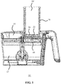
- FIG. 1 An example of such a kitchen appliance 10' is schematically depicted in FIG. 1 , in which the food processing chamber 12 is covered by a lid 14 from which the feed tube 16 extends, with a cutting blade arrangement 18 at the bottom of the feed tube 16.
- An example of such an arrangement is disclosed in Chinese utility model application CN 205704386 . When such a cutting blade arrangement 16 is present, care has to be taken that the plunger or push rod 20' does not contact the cutting blade arrangement to avoid damage to the plunger and/or cutting blade arrangement.
- the feed tube 16 may comprise a stop that ensures that a clearance remains between the plunger 20' and the cutting blade arrangement 18 when the plunger is fully inserted into the feed tube. However, this leaves a residual portion of the food item fed into the kitchen appliance in this clearance, which may be left behind in this clearance when the plunger 20' is pulled out of the feed tube 16 by the user of the kitchen appliance.
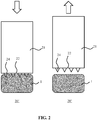
- FIG. 2 This is schematically depicted in FIG. 2 , in which a portion 1 of a food item is secured on the surface 22 of the plunger 20' by an arrangement of spikes 24 when the plunger 20' is pushed into the feed tube 16 as symbolized by the downward pointing block arrow.
- the portion 1 of the food item may slide off the arrangement of spikes 24 and remain in the clearance at the bottom of the feed tube 16. This is of course undesirable, as it requires the user to dismantle the kitchen appliance in order to remove this residual portion of the food item from the feed tube, e.g. for cleaning purposes or to allow another food item portion to be fed into the feed tube.
- the present invention seeks to provide a plunger for engaging with a feed tube of a kitchen appliance that does not suffer from the aforementioned problem.
- the present invention further seeks to provide a kitchen appliance having such a plunger.
- a plunger for engaging with a feed tube of a kitchen appliance comprising an elongate body terminating in a surface for engaging with a food item, said surface comprising an arrangement of spikes for engaging with the food item to prevent twisting of the food item relative to said surface; and at least one grab hook for engaging with the food item to prevent release of the food item from said surface. Due to the presence of the at least one grab hook of the surface of the plunger against which the food item is secured, the release of a residue of the food item from the plunger in the feed tube when pulling the plunger from the feed tube is avoided.
- each grab hook terminates in a tapered edge for cutting into the food item such that such a grab hook can more easily penetrate and secure into the food item.
- the at least one grab hook comprises a closed loop extending from said surface and delimiting at least one hole within said closed loop.
- each closed loop may be flanked by a pair of opposing further spikes for guiding a portion of the food item into the at least one hole within said closed loop.
- Such further spikes may have a multi-faceted surface, preferably with one of said surface facets facing the at least one hole in the closed loop of the grab hook such that a force pushing the portion of the food item onto the further spikes is redirected by the surface facets in the direction of the at least one hole in the further loop of the grab hook, thereby pushing the portion of the food item into the at least one hole of the closed loop of the grab hook in a particularly effective manner.
- Each further spike may be shorter than any of the spikes of the arrangement of spikes. This for example may be beneficial where the further spikes are particularly sharp and/or made of metal, such that damage by the further spikes to a surface onto which the plunger is placed may be avoided, e.g. in case the spikes are less sharp than the further spikes.
- the arrangement of spikes is arranged in a radial pattern and the at least one grab hook is arranged within said radial pattern.
- This is a particularly effective arrangement as the radial arrangement of the spikes is particularly effective in preventing rotation of the food item relative to the surface of the plunger, whilst the centred arrangement of the at least one grab hook within the radial pattern of the spikes optimises the hold of the at least one grab hook on the food item.
- the at least one grab hook comprises a plurality of grab hooks, each extending radially away from the centre of said surface to ensure a firm grip of the grab hooks onto the food item.
- the plurality of grab hooks may comprise a first pair of opposing grab hooks along on a first cross-section of the surface and a second pair of opposing grab hooks along on a second cross-section of the surface perpendicular to said first cross-section to achieve such a firm grip.
- cross-section this refers to an imaginary line across the surface and through the centre of the plunger, such as a diagonal or the like.
- the elongate body is a plastic body
- each grab hook is a metal grab hook moulded into said plastic body.
- each grab hook may comprise a straight section extending from said surface and a curved section extending from said straight section embedded in said plastic body to provide a particularly strong anchoring of the grab hooks in the plastic body.
- a kitchen appliance comprising a food processing chamber; a feed tube for feeding food into said food processing chamber, said feed tube being arranged over a cutting blade arrangement; and the plunger of any of the herein described embodiments, in which the plunger is dimensioned to fit in said feed tube.
- a kitchen appliance benefits from the inclusion of the plunger according to embodiments of the present invention as a residual portion of the food item fed into the feed tube with the plunger does not have to be removed from the feed tube, but instead can be removed from the plunger after removal of the plunger from the feed tube, thereby improving the user experience of such a kitchen appliance.
- the kitchen appliance may further comprise a stop arranged to prevent contact between the cutting blade arrangement and the plunger in order to prevent damage to the plunger and/or cutting blade arrangement in the event of such a contact.
- the cutting blade arrangement may comprise a spiralizer disc to spiralize the food product prior to entry into the food processing chamber of the kitchen appliance.
- the kitchen appliance may further comprise a lid for the food processing chamber, wherein the feed tube and the cutting blade arrangement form part of said lid.
- FIG. 3 schematically depicts a plunger 20 according to an example embodiment of the present invention in perspective view.
- the plunger 20 comprises an elongate body 21 terminating in a surface 22 for engaging with a food item such as a portion of fruit or vegetable for example.
- the elongate body 20 may be made of any suitable material.
- the elongate body 20 is made of plastic, which has the advantage that the plunger 20 can be made in a cost-effective manner, e.g. by a moulding process.
- the elongate body 20 at its end opposing the surface 22 may comprise a handle 28 to allow a user of the plunger 20 to easily grip the plunger 20.
- a handle 28 may have any suitable shape, such as the disc shape schematically depicted in FIG. 3 by way of nonlimiting example.
- the plunger 20 further comprises a plurality of spikes 24 extending from the surface 22, which are intended to penetrate the food item upon pressing the plunger 20 down onto the food item.
- Such spikes 24 typically ensure that the food item cannot easily rotate relative to the surface 22, which for example is desirable when the plunger 20 is used in conjunction with a kitchen appliance comprising a cutting blade arrangement such as a spiralizer disc arrangement, as in such an example scenario undesired rotation of the food item relative to the surface 22 of the plunger 20 may hamper the cutting or slicing of the food item by such a cutting blade arrangement.
- the spikes 24 may be made of any suitable material, e.g. plastic or metal.
- the elongate body 21 may be a monolithic body including the spikes 24.
- the spikes 24 may be moulded into the elongate body 21 of the plunger 20.
- the spikes 24 may have any suitable shape, such as a conical shape or a multi-faceted shape such as a pyramidal shape.
- a multi-faceted shape may provide a more effective securing of the food item onto the surface 22 of the plunger 20.
- the arrangement of spikes 24 comprises a radial distribution of the spikes 24 proximal to the outer perimeter of the surface 22 in which individual spikes 24 are spaced apart from each other in this radial pattern in order to prevent rotation of the food item relative to the surface 22 in a particularly effective manner. This ensures that large food items can be secured against the surface 22 of the plunger 20.
- the surface 22 further comprises at least one grab hook 100, and preferably comprises a plurality of such grab hooks 100 shaped such that upon pushing the food item onto the plunger 20, a portion of the food item is secured or grabbed by the at least one grab hook 100 such that upon a pulling force being exerted onto the plunger 20, e.g. when pulling the plunger 20 from a feed tube 16 of a kitchen appliance, the one or more grab hooks 100 prevent the easy release of the remainder of the food item from the surface 22 of the plunger 20, e.g. by sliding off the spikes 24 as explained above with the aid of FIG. 2 .
- the at least one grab hook preferably is located proximal to the centre of the surface 22, e.g. within the radial arrangement of spikes 24.
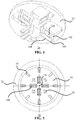
- FIG.4 schematically depicts an example embodiment of such a centered arrangement of grab hooks 100 on a central section of the surface 22 in detail
- FIG. 5 schematically depicts a face on view of the entire surface 22 including this arrangement of grab hooks 100.
- the grab hooks 100 have a body defining a closed loop 102 extending from the surface 22, with such a closed loop 102 delimiting at least one hole 104 extending through the grab hook 100.
- the hole 104 is partitioned into multiple holes are equally feasible, although it is noted that when the holes 104 become particularly small, insertion of a portion of the food item into such holes may become more difficult, and the grab hooks 100 may become more difficult to clean.
- each grab hook 100 may terminate in a tapered edge 106, e.g. a pointed cutting edge, arranged to cut into the food item upon the plunger 20 being pushed into the food item.
- the grab hooks 100 maybe centred in any suitable manner relative to the centre 25 of the surface 22.
- a first pair of grab hooks 100 may be arranged along a first cross-sectional virtual line across the surface 22 and a second pair of grab hooks 100 maybe arranged along a second cross-sectional virtual line across the surface 22 perpendicular to the first cross-sectional virtual line.
- other arrangements of such grab hooks 100 on the surface 22 are equally feasible.
- the surface 22 may further carry an arrangement of further spikes 26.
- the further spikes 26, which may be shorter than the spikes 24, are typically positioned such that each grab hook 100 is flanked by a pair of such further spikes 26.
- such a pair of further spikes 26 may be arranged on opposite ends of the hole 104 through such a grab hook 100 such that upon forcing the plunger 20 into a food item, a portion of the food item interacting with the further spikes 26 is redirected by the further spikes onto the grab hook 100, e.g. into the hole 104 of the grab hook 100.
- the grab hook 100 grabs a portion of the food item, such that when a pulling force is exerted by a user onto the plunger 20, this force is transferred by each grab hook 100 onto the portion of the food item interacting with the grab hook 100, thereby pulling the food item from the feed tube 16 of a food processor and retaining the food item against the surface 22 of the plunger 20.
- the further spikes 26 have angled multi-faceted surfaces to redirect a portion of the food item onto a grab hook 100 in a particularly efficient manner.
- each further spikes 26 may have a pyramidal shape in which one of the angled surface facets of the further spike 26 is facing the hole 104 within the closed loop 102 of a grab hook 100 such that upon interaction with a portion of the food item, this surface facet redirects this portion of the food item directly into the hole 104.
- the further spikes 26 may have any suitable number of surface facets, e.g. three or four surface facets in case of pyramidally shaped further spikes 26.
- the one or more grab hooks 100 maybe made of any suitable material.
- the grab hooks 100 may be formed as plastic hooks that are an integral part of the elongate body 22 of the plunger 20.
- the grab hooks 100 are metal hooks that are molded into the plastic elongate body 21 of the plunger 20, as schematically depicted in FIG. 6 , in order to increase the strength of the grab hooks 100.
- each grab hook 100 may have a straight section in a cross-sectional view, e.g. the closed loop 102, extending from the surface 22 of the plunger 20 and a curved section 103 in the same cross-sectional view that extends from the straight section 102 of the grab hook 100 and is embedded, i.e. moulded, into the plastic elongate body 21 of the plunger 20.
- the plunger 20 comprises a centred arrangement of grab hooks 100 each comprising a closed loop 102 extending from the surface 22 of the plunger 20 and delimiting a hole 104 as shown in FIG. 4 for instance.
- Each hole 104 is flanked by a pair of multi-faceted further spikes 26 as previously explained, with one of said surface facets facing the hole 104.
- This arrangement of grab hooks 100 and further spikes 26 lies within a radial distribution of spikes 24 proximal to the outer perimeter of the surface 22 such that upon pressing the plunger 20 into the food item 1 as indicated by the downward pointing block arrow, the spikes 24 secure the food item 1 against the surface 22 such that the food item 1 cannot easily rotate relative to the surface 22, whereas the arrangement of further spikes 26 redirect the downward force as indicated by arrows A and A' causing a portion of the food item 1 to be lodged into the opening or hole 104 through the grab hook 100. Consequently, when exerting an upward force onto the plunger 20, e.g.
- FIG. 8 schematically depicts a cut away perspective view of a kitchen appliance 10 according to an example embodiment of the present invention.
- the kitchen appliance 10 comprises a food processing chamber 12 for processing food introduced into the food processing chamber 12.
- Such food processing is not limited to a particular type of food processing and for example may include one or more of food preparation such as food cooking, steaming, frying, poaching or the like, food dicing, cutting, slicing, grinding or the like, food mixing, stirring or the like, and so on.
- the kitchen appliance 10 further comprises a feed tube 16 for introducing food items into the food processing chamber 12.
- the feed tube 16 may form part of a lid 14 for covering the food processing chamber 12, e.g. may extend from such a lid 14.
- a feed tube may be arranged over the food preparation chamber 12 in any suitable manner.
- the kitchen appliance 10 further comprises the plunger 20 according to any of the previously described embodiments of the present invention.
- the plunger 20 is typically dimensioned such that it fits into the feed tube 16.
- the plunger 20 and the feed tube 16 may have any suitable matching cross-sectional shape, such as a circular shape, oblong shape and so on.
- a cutting blade arrangement 18 may be arranged to cut the food item forced into the feed tube 16 with the plunger or push rod 20 prior to introduction of this food item into the food processing chamber 12.
- a cutting blade arrangement 18 may comprise a spiralizer disc to spiralize (e.g. cut into curled ribbons) the food item introduced into the feed tube 16.
- a stop 19 may be present within the feed tube 16. Such a stop 19 may be arranged in any suitable manner, e.g.
- the cutting blade arrangement 18 extends from a surface comprising the cutting blade arrangement 18 or may be shaped as a protruding ring or portions thereof on the inner side wall of the feed tube 16.
- Other suitable arrangements of such a stop 19 will be immediately apparent to the skilled person. Due to the presence of the one or more grab hooks 100 on the surface 22 of the plunger 20, the residual portion of the food item feeling the clearance between the plunger 20 and the cutting blade arrangement 18 as defined by the position and/or dimensions of the stop 19 can be removed from the feed tube 16 with the plunger 20 by pulling the plunger 20 from the feed tube 16, thereby obviating the need for a user of the kitchen appliance 10 to dismantle the appliance, e.g.
- the kitchen appliance 10 is more user-friendly compared to for example the kitchen appliance 10' depicted in FIG. 1 , as it does not require removal of such a residual portion of a food item from the feed tube 16.
Landscapes
- Engineering & Computer Science (AREA)
- Food Science & Technology (AREA)
- Mechanical Engineering (AREA)
- Food-Manufacturing Devices (AREA)
Abstract
Description
- The present invention relates to a plunger for engaging with a feed tube of a kitchen appliance, the plunger comprising an elongate body terminating in a surface for engaging with a food item, said surface comprising an arrangement of spikes for engaging with the food item to prevent twisting of the food item relative to said surface.
- The present invention further relates to a kitchen appliance including such a feed tube and plunger.
- Many kitchen appliances comprise a feed tube through which a food item can be fed into the food processing chamber of the appliance. Such a feed tube for example may be located in the lid covering such a food processing chamber. The advantage of such a feed tube is that the user of the kitchen appliance does not have to remove the lid from the food processing chamber to gain access thereto. This for example allows the user to feed food items into the kitchen appliance whilst the appliance is in operation, which therefore improves the user experience with such a kitchen appliance. In order to facilitate the feeding of such food items through the feed tube of such a kitchen appliance, a plunger or pushrod may be provided with the appliance that fits into the feed tube. This for example may improve the safety of operation of the kitchen appliance whilst at the same time preventing food from being forced out of the food preparation chamber through the feed tube.
- Some kitchen appliances that are equipped with such a feed tube may include a cutting blade arrangement at the bottom of the feed tube, such as a spiralizer blade arrangement. An example of such a kitchen appliance 10' is schematically depicted in
FIG. 1 , in which thefood processing chamber 12 is covered by alid 14 from which thefeed tube 16 extends, with acutting blade arrangement 18 at the bottom of thefeed tube 16. An example of such an arrangement is disclosed in Chinese utility model applicationCN 205704386 . When such acutting blade arrangement 16 is present, care has to be taken that the plunger or push rod 20' does not contact the cutting blade arrangement to avoid damage to the plunger and/or cutting blade arrangement. To this end, thefeed tube 16 may comprise a stop that ensures that a clearance remains between the plunger 20' and thecutting blade arrangement 18 when the plunger is fully inserted into the feed tube. However, this leaves a residual portion of the food item fed into the kitchen appliance in this clearance, which may be left behind in this clearance when the plunger 20' is pulled out of thefeed tube 16 by the user of the kitchen appliance. - This is schematically depicted in
FIG. 2 , in which a portion 1 of a food item is secured on thesurface 22 of the plunger 20' by an arrangement ofspikes 24 when the plunger 20' is pushed into thefeed tube 16 as symbolized by the downward pointing block arrow. However, when pulling the plunger 20' from thefeed tube 16 as symbolized by the upward pointing block arrow, the portion 1 of the food item may slide off the arrangement ofspikes 24 and remain in the clearance at the bottom of thefeed tube 16. This is of course undesirable, as it requires the user to dismantle the kitchen appliance in order to remove this residual portion of the food item from the feed tube, e.g. for cleaning purposes or to allow another food item portion to be fed into the feed tube. - The present invention seeks to provide a plunger for engaging with a feed tube of a kitchen appliance that does not suffer from the aforementioned problem.
- The present invention further seeks to provide a kitchen appliance having such a plunger.
- According to an aspect, there is provided a plunger for engaging with a feed tube of a kitchen appliance, the plunger comprising an elongate body terminating in a surface for engaging with a food item, said surface comprising an arrangement of spikes for engaging with the food item to prevent twisting of the food item relative to said surface; and at least one grab hook for engaging with the food item to prevent release of the food item from said surface. Due to the presence of the at least one grab hook of the surface of the plunger against which the food item is secured, the release of a residue of the food item from the plunger in the feed tube when pulling the plunger from the feed tube is avoided. Consequently, an improved user experience is provided due to the fact that the user does not have to remove such a residue from the feed tube, which can be cumbersome. Instead, the user can simply remove the food item residue from the plunger after removal of the plunger from the feed tube, which is significantly easier to achieve and does not require the disassembly of the kitchen appliance.
- In an embodiment, each grab hook terminates in a tapered edge for cutting into the food item such that such a grab hook can more easily penetrate and secure into the food item.
- In a preferred embodiment, the at least one grab hook comprises a closed loop extending from said surface and delimiting at least one hole within said closed loop. With such an arrangement, when the plunger is pushed into the food item, part of the food item will be forced into the at least one hole within such a closed loop such that when the plunger is pulled from the feed tube, the at least one grab hook holds the food item in place by virtue of the part of the food item within such a hole.
- To further assist the forcing of such part of the food item in such a hole, each closed loop may be flanked by a pair of opposing further spikes for guiding a portion of the food item into the at least one hole within said closed loop. Such further spikes may have a multi-faceted surface, preferably with one of said surface facets facing the at least one hole in the closed loop of the grab hook such that a force pushing the portion of the food item onto the further spikes is redirected by the surface facets in the direction of the at least one hole in the further loop of the grab hook, thereby pushing the portion of the food item into the at least one hole of the closed loop of the grab hook in a particularly effective manner. Each further spike may be shorter than any of the spikes of the arrangement of spikes. This for example may be beneficial where the further spikes are particularly sharp and/or made of metal, such that damage by the further spikes to a surface onto which the plunger is placed may be avoided, e.g. in case the spikes are less sharp than the further spikes.
- In an embodiment, the arrangement of spikes is arranged in a radial pattern and the at least one grab hook is arranged within said radial pattern. This is a particularly effective arrangement as the radial arrangement of the spikes is particularly effective in preventing rotation of the food item relative to the surface of the plunger, whilst the centred arrangement of the at least one grab hook within the radial pattern of the spikes optimises the hold of the at least one grab hook on the food item.
- Preferably, the at least one grab hook comprises a plurality of grab hooks, each extending radially away from the centre of said surface to ensure a firm grip of the grab hooks onto the food item. For example, the plurality of grab hooks may comprise a first pair of opposing grab hooks along on a first cross-section of the surface and a second pair of opposing grab hooks along on a second cross-section of the surface perpendicular to said first cross-section to achieve such a firm grip. In the context of the present application, it should be understood that where reference is made to the term cross-section, this refers to an imaginary line across the surface and through the centre of the plunger, such as a diagonal or the like.
- In a particular embodiment, the elongate body is a plastic body, and each grab hook is a metal grab hook moulded into said plastic body. This yields a particularly strong arrangement, thereby reducing the risk of accidental damage to the one or more grab hooks, e.g. compared to an arrangement in which the grab hooks are an integral part of the plastic body, that is, a one-piece plastic body of which the grab hooks form part.
- To this end, each grab hook may comprise a straight section extending from said surface and a curved section extending from said straight section embedded in said plastic body to provide a particularly strong anchoring of the grab hooks in the plastic body.
- According to another aspect, there is provided a kitchen appliance comprising a food processing chamber; a feed tube for feeding food into said food processing chamber, said feed tube being arranged over a cutting blade arrangement; and the plunger of any of the herein described embodiments, in which the plunger is dimensioned to fit in said feed tube. Such a kitchen appliance benefits from the inclusion of the plunger according to embodiments of the present invention as a residual portion of the food item fed into the feed tube with the plunger does not have to be removed from the feed tube, but instead can be removed from the plunger after removal of the plunger from the feed tube, thereby improving the user experience of such a kitchen appliance.
- The kitchen appliance may further comprise a stop arranged to prevent contact between the cutting blade arrangement and the plunger in order to prevent damage to the plunger and/or cutting blade arrangement in the event of such a contact.
- In particular embodiments, the cutting blade arrangement may comprise a spiralizer disc to spiralize the food product prior to entry into the food processing chamber of the kitchen appliance.
- The kitchen appliance may further comprise a lid for the food processing chamber, wherein the feed tube and the cutting blade arrangement form part of said lid.
- Embodiments of the invention are described in more detail and by way of nonlimiting examples with reference to the accompanying drawings, wherein:
-
FIG. 1 schematically depicts a cross-sectional view of a prior art kitchen appliance; -
FIG. 2 schematically depicts a cross-sectional view of the operating principle of a plunger of such a prior art kitchen appliance; -
FIG. 3 schematically depicts a perspective view of a plunger for a kitchen appliance according to an embodiment of the present invention; -
FIG. 4 schematically depicts an aspect of the plunger ofFIG. 3 in more detail; -
FIG. 5 schematically depicts a bottom view of a plunger for a kitchen appliance according to an embodiment of the present invention; -
FIG. 6 schematically depicts a cross-sectional view of part of a plunger for a kitchen appliance according to an embodiment of the present invention; -
FIG. 7 schematically depicts a cross-sectional view of the operating principle of part of a plunger for a kitchen appliance according to an embodiment of the present invention; and -
FIG. 8 schematically depicts a perspective cut open view of a kitchen appliance according to an example embodiment of the present invention. - It should be understood that the Figures are merely schematic and are not drawn to scale. It should also be understood that the same reference numerals are used throughout the Figures to indicate the same or similar parts.
-
FIG. 3 schematically depicts aplunger 20 according to an example embodiment of the present invention in perspective view. Theplunger 20 comprises anelongate body 21 terminating in asurface 22 for engaging with a food item such as a portion of fruit or vegetable for example. Theelongate body 20 may be made of any suitable material. In a preferred embodiment, theelongate body 20 is made of plastic, which has the advantage that theplunger 20 can be made in a cost-effective manner, e.g. by a moulding process. Theelongate body 20 at its end opposing thesurface 22 may comprise ahandle 28 to allow a user of theplunger 20 to easily grip theplunger 20. Such ahandle 28 may have any suitable shape, such as the disc shape schematically depicted inFIG. 3 by way of nonlimiting example. - In other to secure the food item against the
surface 22, theplunger 20 further comprises a plurality ofspikes 24 extending from thesurface 22, which are intended to penetrate the food item upon pressing theplunger 20 down onto the food item.Such spikes 24 typically ensure that the food item cannot easily rotate relative to thesurface 22, which for example is desirable when theplunger 20 is used in conjunction with a kitchen appliance comprising a cutting blade arrangement such as a spiralizer disc arrangement, as in such an example scenario undesired rotation of the food item relative to thesurface 22 of theplunger 20 may hamper the cutting or slicing of the food item by such a cutting blade arrangement. Thespikes 24 may be made of any suitable material, e.g. plastic or metal. For example, theelongate body 21 may be a monolithic body including thespikes 24. Alternatively, thespikes 24 may be moulded into theelongate body 21 of theplunger 20. Thespikes 24 may have any suitable shape, such as a conical shape or a multi-faceted shape such as a pyramidal shape. A multi-faceted shape may provide a more effective securing of the food item onto thesurface 22 of theplunger 20. Preferably, the arrangement ofspikes 24 comprises a radial distribution of thespikes 24 proximal to the outer perimeter of thesurface 22 in which individual spikes 24 are spaced apart from each other in this radial pattern in order to prevent rotation of the food item relative to thesurface 22 in a particularly effective manner. This ensures that large food items can be secured against thesurface 22 of theplunger 20. - The
surface 22 further comprises at least onegrab hook 100, and preferably comprises a plurality of such grab hooks 100 shaped such that upon pushing the food item onto theplunger 20, a portion of the food item is secured or grabbed by the at least onegrab hook 100 such that upon a pulling force being exerted onto theplunger 20, e.g. when pulling theplunger 20 from afeed tube 16 of a kitchen appliance, the one or more grab hooks 100 prevent the easy release of the remainder of the food item from thesurface 22 of theplunger 20, e.g. by sliding off thespikes 24 as explained above with the aid ofFIG. 2 . In order to optimize the grip of the at least onegrab hook 100 on the food item, the at least one grab hook preferably is located proximal to the centre of thesurface 22, e.g. within the radial arrangement ofspikes 24. -
FIG.4 schematically depicts an example embodiment of such a centered arrangement of grab hooks 100 on a central section of thesurface 22 in detail, whilstFIG. 5 schematically depicts a face on view of theentire surface 22 including this arrangement of grab hooks 100. In this arrangement, the grab hooks 100 have a body defining aclosed loop 102 extending from thesurface 22, with such aclosed loop 102 delimiting at least onehole 104 extending through thegrab hook 100. Of course, arrangements in which thehole 104 is partitioned into multiple holes are equally feasible, although it is noted that when theholes 104 become particularly small, insertion of a portion of the food item into such holes may become more difficult, and the grab hooks 100 may become more difficult to clean. Theclosed loop 102 of eachgrab hook 100 may terminate in atapered edge 106, e.g. a pointed cutting edge, arranged to cut into the food item upon theplunger 20 being pushed into the food item. The grab hooks 100 maybe centred in any suitable manner relative to thecentre 25 of thesurface 22. For example, a first pair of grab hooks 100 may be arranged along a first cross-sectional virtual line across thesurface 22 and a second pair of grab hooks 100 maybe arranged along a second cross-sectional virtual line across thesurface 22 perpendicular to the first cross-sectional virtual line. Of course, other arrangements of such grab hooks 100 on thesurface 22 are equally feasible. - In order to assist with the direction of a portion of the food item onto the at least one
grab hook 100, e.g. into theholes 104 of such grab hooks, thesurface 22 may further carry an arrangement of further spikes 26. The further spikes 26, which may be shorter than thespikes 24, are typically positioned such that eachgrab hook 100 is flanked by a pair of such further spikes 26. For example, such a pair offurther spikes 26 may be arranged on opposite ends of thehole 104 through such agrab hook 100 such that upon forcing theplunger 20 into a food item, a portion of the food item interacting with thefurther spikes 26 is redirected by the further spikes onto thegrab hook 100, e.g. into thehole 104 of thegrab hook 100. In this manner, thegrab hook 100 grabs a portion of the food item, such that when a pulling force is exerted by a user onto theplunger 20, this force is transferred by eachgrab hook 100 onto the portion of the food item interacting with thegrab hook 100, thereby pulling the food item from thefeed tube 16 of a food processor and retaining the food item against thesurface 22 of theplunger 20. In a preferred embodiment, thefurther spikes 26 have angled multi-faceted surfaces to redirect a portion of the food item onto agrab hook 100 in a particularly efficient manner. For example, each further spikes 26 may have a pyramidal shape in which one of the angled surface facets of thefurther spike 26 is facing thehole 104 within theclosed loop 102 of agrab hook 100 such that upon interaction with a portion of the food item, this surface facet redirects this portion of the food item directly into thehole 104. The further spikes 26 may have any suitable number of surface facets, e.g. three or four surface facets in case of pyramidally shaped further spikes 26. - The one or more grab hooks 100 maybe made of any suitable material. For example, the grab hooks 100 may be formed as plastic hooks that are an integral part of the
elongate body 22 of theplunger 20. Preferably, the grab hooks 100 are metal hooks that are molded into the plasticelongate body 21 of theplunger 20, as schematically depicted inFIG. 6 , in order to increase the strength of the grab hooks 100. In this embodiment, eachgrab hook 100 may have a straight section in a cross-sectional view, e.g. theclosed loop 102, extending from thesurface 22 of theplunger 20 and acurved section 103 in the same cross-sectional view that extends from thestraight section 102 of thegrab hook 100 and is embedded, i.e. moulded, into the plasticelongate body 21 of theplunger 20. - The operating principle of a preferred embodiment of the
plunger 20 is schematically depicted in the cross-sectional view of the bottom part of theplunger 20 inFIG. 7 . In this preferred embodiment, theplunger 20 comprises a centred arrangement of grab hooks 100 each comprising aclosed loop 102 extending from thesurface 22 of theplunger 20 and delimiting ahole 104 as shown inFIG. 4 for instance. Eachhole 104 is flanked by a pair of multi-facetedfurther spikes 26 as previously explained, with one of said surface facets facing thehole 104. This arrangement of grab hooks 100 andfurther spikes 26 lies within a radial distribution ofspikes 24 proximal to the outer perimeter of thesurface 22 such that upon pressing theplunger 20 into the food item 1 as indicated by the downward pointing block arrow, thespikes 24 secure the food item 1 against thesurface 22 such that the food item 1 cannot easily rotate relative to thesurface 22, whereas the arrangement offurther spikes 26 redirect the downward force as indicated by arrows A and A' causing a portion of the food item 1 to be lodged into the opening orhole 104 through thegrab hook 100. Consequently, when exerting an upward force onto theplunger 20, e.g. when pulling theplunger 20 from afeed tube 16 of a kitchen appliance, the remainder of the food item 1 is lifted from thisfeed tube 16 owing to the portion of the food item 1 being lodged into the one or more grab hooks 100 preventing easy release of the remainder of the food item 1 from theplunger 20. -
FIG. 8 schematically depicts a cut away perspective view of akitchen appliance 10 according to an example embodiment of the present invention. Thekitchen appliance 10 comprises afood processing chamber 12 for processing food introduced into thefood processing chamber 12. Such food processing is not limited to a particular type of food processing and for example may include one or more of food preparation such as food cooking, steaming, frying, poaching or the like, food dicing, cutting, slicing, grinding or the like, food mixing, stirring or the like, and so on. - The
kitchen appliance 10 further comprises afeed tube 16 for introducing food items into thefood processing chamber 12. For example, thefeed tube 16 may form part of alid 14 for covering thefood processing chamber 12, e.g. may extend from such alid 14. However, it is noted for the avoidance of doubt that such a feed tube may be arranged over thefood preparation chamber 12 in any suitable manner. Thekitchen appliance 10 further comprises theplunger 20 according to any of the previously described embodiments of the present invention. As will be readily understood by the skilled person, theplunger 20 is typically dimensioned such that it fits into thefeed tube 16. Theplunger 20 and thefeed tube 16 may have any suitable matching cross-sectional shape, such as a circular shape, oblong shape and so on. - At the bottom of the
feed tube 16, e.g. within thelid 14, acutting blade arrangement 18 may be arranged to cut the food item forced into thefeed tube 16 with the plunger or pushrod 20 prior to introduction of this food item into thefood processing chamber 12. For example, such acutting blade arrangement 18 may comprise a spiralizer disc to spiralize (e.g. cut into curled ribbons) the food item introduced into thefeed tube 16. In order to prevent potentially damaging contact between theend surface 22 of theplunger 20 and thecutting blade arrangement 18, astop 19 may be present within thefeed tube 16. Such astop 19 may be arranged in any suitable manner, e.g. extend from a surface comprising thecutting blade arrangement 18 or may be shaped as a protruding ring or portions thereof on the inner side wall of thefeed tube 16. Other suitable arrangements of such astop 19 will be immediately apparent to the skilled person. Due to the presence of the one or more grab hooks 100 on thesurface 22 of theplunger 20, the residual portion of the food item feeling the clearance between theplunger 20 and thecutting blade arrangement 18 as defined by the position and/or dimensions of thestop 19 can be removed from thefeed tube 16 with theplunger 20 by pulling theplunger 20 from thefeed tube 16, thereby obviating the need for a user of thekitchen appliance 10 to dismantle the appliance, e.g. by removal of thelid 14, in order to remove such a residual portion of the food item from the bottom of thefeed tube 16. Consequently, thekitchen appliance 10 according to embodiments of the present invention is more user-friendly compared to for example the kitchen appliance 10' depicted inFIG. 1 , as it does not require removal of such a residual portion of a food item from thefeed tube 16. - It should be noted that the above-mentioned embodiments illustrate rather than limit the invention, and that those skilled in the art will be able to design many alternative embodiments without departing from the scope of the appended claims. In the claims, any reference signs placed between parentheses shall not be construed as limiting the claim. The word "comprising" does not exclude the presence of elements or steps other than those listed in a claim. The word "a" or "an" preceding an element does not exclude the presence of a plurality of such elements. The invention can be implemented by means of hardware comprising several distinct elements. In the device claim enumerating several means, several of these means can be embodied by one and the same item of hardware. The mere fact that certain measures are recited in mutually different dependent claims does not indicate that a combination of these measures cannot be used to advantage.
Claims (15)
- A plunger (20) for engaging with a feed tube (16) of a kitchen appliance (10), the plunger comprising an elongate body (21) terminating in a surface (22) for engaging with a food item (1), said surface comprising:an arrangement of spikes (24) for engaging with the food item to prevent twisting of the food item relative to said surface; andat least one grab hook (100) for engaging with the food item to prevent release of the food item from said surface.
- The plunger (20) of claim 1, wherein each grab hook (100) terminates in a tapered edge (106) for cutting into the food item (1).
- The plunger (20) of claim 1 or 2, wherein the at least one grab hook (100) comprises a closed loop (102) extending from said surface (22) and delimiting at least one hole (104) within said closed loop.
- The plunger (20) of claim 3, wherein each closed loop (102) is flanked by a pair of opposing further spikes (26) for guiding a portion of the food item (1) into the at least one hole within said closed loop.
- The plunger (20) of claim 4, wherein each further spike (26) has a multi-faceted surface.
- The plunger (20) of claim 4 or 5, wherein each further spike (26) is shorter than any of the spikes (24) of the arrangement of spikes.
- The plunger (20) of any of claims 1-6, wherein the arrangement of spikes (24) is arranged in a radial pattern and the at least one grab hook (100) is arranged within said radial pattern.
- The plunger (20) of any of claims 1-7, wherein the at least one grab hook (100) comprises a plurality of grab hooks, each extending radially away from the centre (25) of said surface (22).
- The plunger (20) of claim 8, wherein the plurality of grab hooks (100) comprises a first pair of opposing grab hooks along on a first cross-section of the surface (22) and a second pair of opposing grab hooks along on a second cross-section of the surface perpendicular to said first cross-section.
- The plunger (20) of any of claims 1-9, wherein the elongate body (21) is a plastic body, and each grab hook (100) is a metal grab hook moulded into said plastic body.
- The plunger (20) of claim 10, wherein each grab hook (100) comprises a straight section (102) extending from said surface (22) and a curved section (103) extending from said straight section embedded in said plastic body (21).
- A kitchen appliance (10) comprising:
a food processing chamber (12);a feed tube (16) for feeding food (1) into said food processing chamber, said feed tube being arranged over a cutting blade arrangement (18); andthe plunger (20) of any of claims 1-11 dimensioned to fit in said feed tube. - The kitchen appliance (10) of claim 12, further comprising a stop (19) arranged to prevent contact between the cutting blade arrangement (18) and the plunger (20).
- The kitchen appliance (10) of claim 12 or 13, wherein the cutting blade arrangement (18) comprises a spiralizer disc.
- The kitchen appliance (10) of any of claims 12-14, further comprising a lid (14) for the food processing chamber (12), wherein the feed tube (16) and the cutting blade arrangement (18) form part of said lid.
Applications Claiming Priority (1)
| Application Number | Priority Date | Filing Date | Title |
|---|---|---|---|
| CN201910107917.4A CN111513572B (en) | 2019-02-02 | 2019-02-02 | Kitchen utensils pistons and kitchen utensils |
Publications (2)
| Publication Number | Publication Date |
|---|---|
| EP3689205A1 true EP3689205A1 (en) | 2020-08-05 |
| EP3689205B1 EP3689205B1 (en) | 2024-08-14 |
Family
ID=67514475
Family Applications (1)
| Application Number | Title | Priority Date | Filing Date |
|---|---|---|---|
| EP19189539.0A Active EP3689205B1 (en) | 2019-02-02 | 2019-08-01 | Plunger for kitchen appliance and kitchen appliance |
Country Status (3)
| Country | Link |
|---|---|
| EP (1) | EP3689205B1 (en) |
| CN (1) | CN111513572B (en) |
| PL (1) | PL3689205T3 (en) |
Citations (3)
| Publication number | Priority date | Publication date | Assignee | Title |
|---|---|---|---|---|
| CN205704386U (en) | 2016-04-22 | 2016-11-23 | 深圳市联创三金电器有限公司 | The shredding slicing device of the central rotation cutting of energy automatic centering |
| CN207127954U (en) * | 2017-08-04 | 2018-03-23 | 泓首翔电器(深圳)有限公司 | A kind of continuous filament cutting mechanism for food preparation |
| EP3427622A1 (en) * | 2017-07-14 | 2019-01-16 | Huiyang Allan Plastics & Electric Industries Co., Limited | A rotary cutting machine |
Family Cites Families (9)
| Publication number | Priority date | Publication date | Assignee | Title |
|---|---|---|---|---|
| AU690868B2 (en) * | 1993-11-04 | 1998-04-30 | Comalco Aluminium Limited | Vacuum lifting device |
| ATE338500T1 (en) * | 2001-11-30 | 2006-09-15 | Sirman S P A | MACHINE FOR WASHING VEGETABLES AND MOLLUSC |
| ITRE20030053A1 (en) * | 2003-05-22 | 2004-11-23 | Edilmatic S R L | "IMPROVED GRIPPING DEVICE FOR ATTACHING A HEAVY CEMENTITIOUS BODY TO AN ATTACHING BODY" |
| CN201101448Y (en) * | 2007-11-17 | 2008-08-20 | 李阳松 | Tool bit for kitchen use |
| FR3028792B1 (en) * | 2014-11-26 | 2016-12-23 | Gastronome | INSTALLATION FOR CUTTING INTO PIECES OF EXTENSIVE FOODSTUFFS, ESPECIALLY MEAT OR FISH PIECES |
| CN105397822B (en) * | 2015-12-17 | 2018-04-20 | 浙江畅尔智能装备股份有限公司 | A kind of end gripper |
| CN107296542B (en) * | 2016-04-14 | 2023-05-26 | 深圳市联创三金电器有限公司 | Shredding and slicing device |
| CN107184113A (en) * | 2017-07-14 | 2017-09-22 | 成都智宸科技有限公司 | A kind of energy saving and environment friendly outdoor crock oven |
| CN210158487U (en) * | 2019-02-02 | 2020-03-20 | 皇家飞利浦有限公司 | Piston for a kitchen appliance and kitchen appliance |
-
2019
- 2019-02-02 CN CN201910107917.4A patent/CN111513572B/en active Active
- 2019-08-01 EP EP19189539.0A patent/EP3689205B1/en active Active
- 2019-08-01 PL PL19189539.0T patent/PL3689205T3/en unknown
Patent Citations (3)
| Publication number | Priority date | Publication date | Assignee | Title |
|---|---|---|---|---|
| CN205704386U (en) | 2016-04-22 | 2016-11-23 | 深圳市联创三金电器有限公司 | The shredding slicing device of the central rotation cutting of energy automatic centering |
| EP3427622A1 (en) * | 2017-07-14 | 2019-01-16 | Huiyang Allan Plastics & Electric Industries Co., Limited | A rotary cutting machine |
| CN207127954U (en) * | 2017-08-04 | 2018-03-23 | 泓首翔电器(深圳)有限公司 | A kind of continuous filament cutting mechanism for food preparation |
Also Published As
| Publication number | Publication date |
|---|---|
| CN111513572B (en) | 2025-07-04 |
| EP3689205B1 (en) | 2024-08-14 |
| CN111513572A (en) | 2020-08-11 |
| PL3689205T3 (en) | 2024-10-28 |
Similar Documents
| Publication | Publication Date | Title |
|---|---|---|
| US4674690A (en) | Feed tube protector retaining apparatus | |
| US4614306A (en) | Pivoting protector for food processor feed tube | |
| EP2946700B1 (en) | Avocado pitting device | |
| US7114258B2 (en) | Fruit stone remover | |
| GB2088201A (en) | A holder for food-stuff to be comminuted by a culinary device | |
| US8276277B2 (en) | Device for holding and preparing a food product | |
| EP3689205B1 (en) | Plunger for kitchen appliance and kitchen appliance | |
| CN210158487U (en) | Piston for a kitchen appliance and kitchen appliance | |
| JPH0225485Y2 (en) | ||
| KR20110094371A (en) | Error cutting machine | |
| EP2399492B1 (en) | Multiple kitchen utensil | |
| US10765263B2 (en) | Food skewer | |
| JP7511942B1 (en) | kitchenware | |
| US5844215A (en) | Food preparing tool | |
| US3717088A (en) | Appliances for cutting an egg shell | |
| JP3190072U (en) | Cooking utensil with cutting blade | |
| KR101299672B1 (en) | A safety opener having one-touch opener | |
| WO2015121965A1 (en) | Kitchen utensil provided with cutting blade | |
| JP3125666B2 (en) | Bread extractor for bread maker | |
| JP3037906U (en) | Cooker aids | |
| CN211432182U (en) | Peeling machine | |
| JP2025024195A (en) | Attachments and kitchen equipment | |
| JP3198478U (en) | Cookware with fork | |
| JP3198582U (en) | Cooking utensils with forks and spoons at both ends | |
| JP5860560B1 (en) | Cookware with knife |
Legal Events
| Date | Code | Title | Description |
|---|---|---|---|
| PUAI | Public reference made under article 153(3) epc to a published international application that has entered the european phase |
Free format text: ORIGINAL CODE: 0009012 |
|
| STAA | Information on the status of an ep patent application or granted ep patent |
Free format text: STATUS: THE APPLICATION HAS BEEN PUBLISHED |
|
| AK | Designated contracting states |
Kind code of ref document: A1 Designated state(s): AL AT BE BG CH CY CZ DE DK EE ES FI FR GB GR HR HU IE IS IT LI LT LU LV MC MK MT NL NO PL PT RO RS SE SI SK SM TR |
|
| AX | Request for extension of the european patent |
Extension state: BA ME |
|
| STAA | Information on the status of an ep patent application or granted ep patent |
Free format text: STATUS: REQUEST FOR EXAMINATION WAS MADE |
|
| 17P | Request for examination filed |
Effective date: 20210205 |
|
| RBV | Designated contracting states (corrected) |
Designated state(s): AL AT BE BG CH CY CZ DE DK EE ES FI FR GB GR HR HU IE IS IT LI LT LU LV MC MK MT NL NO PL PT RO RS SE SI SK SM TR |
|
| RAP1 | Party data changed (applicant data changed or rights of an application transferred) |
Owner name: VERSUNI HOLDING B.V. |
|
| GRAP | Despatch of communication of intention to grant a patent |
Free format text: ORIGINAL CODE: EPIDOSNIGR1 |
|
| STAA | Information on the status of an ep patent application or granted ep patent |
Free format text: STATUS: GRANT OF PATENT IS INTENDED |
|
| RIC1 | Information provided on ipc code assigned before grant |
Ipc: A47J 43/18 20060101ALI20240312BHEP Ipc: A47J 43/07 20060101AFI20240312BHEP |
|
| INTG | Intention to grant announced |
Effective date: 20240415 |
|
| GRAS | Grant fee paid |
Free format text: ORIGINAL CODE: EPIDOSNIGR3 |
|
| GRAA | (expected) grant |
Free format text: ORIGINAL CODE: 0009210 |
|
| STAA | Information on the status of an ep patent application or granted ep patent |
Free format text: STATUS: THE PATENT HAS BEEN GRANTED |
|
| AK | Designated contracting states |
Kind code of ref document: B1 Designated state(s): AL AT BE BG CH CY CZ DE DK EE ES FI FR GB GR HR HU IE IS IT LI LT LU LV MC MK MT NL NO PL PT RO RS SE SI SK SM TR |
|
| REG | Reference to a national code |
Ref country code: GB Ref legal event code: FG4D |
|
| REG | Reference to a national code |
Ref country code: CH Ref legal event code: EP |
|
| REG | Reference to a national code |
Ref country code: DE Ref legal event code: R096 Ref document number: 602019056898 Country of ref document: DE |
|
| REG | Reference to a national code |
Ref country code: IE Ref legal event code: FG4D |
|
| REG | Reference to a national code |
Ref country code: NL Ref legal event code: FP |
|
| REG | Reference to a national code |
Ref country code: LT Ref legal event code: MG9D |
|
| PG25 | Lapsed in a contracting state [announced via postgrant information from national office to epo] |
Ref country code: NO Free format text: LAPSE BECAUSE OF FAILURE TO SUBMIT A TRANSLATION OF THE DESCRIPTION OR TO PAY THE FEE WITHIN THE PRESCRIBED TIME-LIMIT Effective date: 20241114 |
|
| REG | Reference to a national code |
Ref country code: AT Ref legal event code: MK05 Ref document number: 1712454 Country of ref document: AT Kind code of ref document: T Effective date: 20240814 |
|
| PG25 | Lapsed in a contracting state [announced via postgrant information from national office to epo] |
Ref country code: FI Free format text: LAPSE BECAUSE OF FAILURE TO SUBMIT A TRANSLATION OF THE DESCRIPTION OR TO PAY THE FEE WITHIN THE PRESCRIBED TIME-LIMIT Effective date: 20240814 Ref country code: GR Free format text: LAPSE BECAUSE OF FAILURE TO SUBMIT A TRANSLATION OF THE DESCRIPTION OR TO PAY THE FEE WITHIN THE PRESCRIBED TIME-LIMIT Effective date: 20241115 Ref country code: PT Free format text: LAPSE BECAUSE OF FAILURE TO SUBMIT A TRANSLATION OF THE DESCRIPTION OR TO PAY THE FEE WITHIN THE PRESCRIBED TIME-LIMIT Effective date: 20241216 |
|
| PG25 | Lapsed in a contracting state [announced via postgrant information from national office to epo] |
Ref country code: BG Free format text: LAPSE BECAUSE OF FAILURE TO SUBMIT A TRANSLATION OF THE DESCRIPTION OR TO PAY THE FEE WITHIN THE PRESCRIBED TIME-LIMIT Effective date: 20240814 |
|
| PG25 | Lapsed in a contracting state [announced via postgrant information from national office to epo] |
Ref country code: LV Free format text: LAPSE BECAUSE OF FAILURE TO SUBMIT A TRANSLATION OF THE DESCRIPTION OR TO PAY THE FEE WITHIN THE PRESCRIBED TIME-LIMIT Effective date: 20240814 |
|
| PG25 | Lapsed in a contracting state [announced via postgrant information from national office to epo] |
Ref country code: IS Free format text: LAPSE BECAUSE OF FAILURE TO SUBMIT A TRANSLATION OF THE DESCRIPTION OR TO PAY THE FEE WITHIN THE PRESCRIBED TIME-LIMIT Effective date: 20241214 Ref country code: AT Free format text: LAPSE BECAUSE OF FAILURE TO SUBMIT A TRANSLATION OF THE DESCRIPTION OR TO PAY THE FEE WITHIN THE PRESCRIBED TIME-LIMIT Effective date: 20240814 |
|
| PG25 | Lapsed in a contracting state [announced via postgrant information from national office to epo] |
Ref country code: HR Free format text: LAPSE BECAUSE OF FAILURE TO SUBMIT A TRANSLATION OF THE DESCRIPTION OR TO PAY THE FEE WITHIN THE PRESCRIBED TIME-LIMIT Effective date: 20240814 |
|
| PG25 | Lapsed in a contracting state [announced via postgrant information from national office to epo] |
Ref country code: ES Free format text: LAPSE BECAUSE OF FAILURE TO SUBMIT A TRANSLATION OF THE DESCRIPTION OR TO PAY THE FEE WITHIN THE PRESCRIBED TIME-LIMIT Effective date: 20240814 Ref country code: RS Free format text: LAPSE BECAUSE OF FAILURE TO SUBMIT A TRANSLATION OF THE DESCRIPTION OR TO PAY THE FEE WITHIN THE PRESCRIBED TIME-LIMIT Effective date: 20241114 |
|
| PG25 | Lapsed in a contracting state [announced via postgrant information from national office to epo] |
Ref country code: RS Free format text: LAPSE BECAUSE OF FAILURE TO SUBMIT A TRANSLATION OF THE DESCRIPTION OR TO PAY THE FEE WITHIN THE PRESCRIBED TIME-LIMIT Effective date: 20241114 Ref country code: PT Free format text: LAPSE BECAUSE OF FAILURE TO SUBMIT A TRANSLATION OF THE DESCRIPTION OR TO PAY THE FEE WITHIN THE PRESCRIBED TIME-LIMIT Effective date: 20241216 Ref country code: NO Free format text: LAPSE BECAUSE OF FAILURE TO SUBMIT A TRANSLATION OF THE DESCRIPTION OR TO PAY THE FEE WITHIN THE PRESCRIBED TIME-LIMIT Effective date: 20241114 Ref country code: LV Free format text: LAPSE BECAUSE OF FAILURE TO SUBMIT A TRANSLATION OF THE DESCRIPTION OR TO PAY THE FEE WITHIN THE PRESCRIBED TIME-LIMIT Effective date: 20240814 Ref country code: IS Free format text: LAPSE BECAUSE OF FAILURE TO SUBMIT A TRANSLATION OF THE DESCRIPTION OR TO PAY THE FEE WITHIN THE PRESCRIBED TIME-LIMIT Effective date: 20241214 Ref country code: HR Free format text: LAPSE BECAUSE OF FAILURE TO SUBMIT A TRANSLATION OF THE DESCRIPTION OR TO PAY THE FEE WITHIN THE PRESCRIBED TIME-LIMIT Effective date: 20240814 Ref country code: GR Free format text: LAPSE BECAUSE OF FAILURE TO SUBMIT A TRANSLATION OF THE DESCRIPTION OR TO PAY THE FEE WITHIN THE PRESCRIBED TIME-LIMIT Effective date: 20241115 Ref country code: FI Free format text: LAPSE BECAUSE OF FAILURE TO SUBMIT A TRANSLATION OF THE DESCRIPTION OR TO PAY THE FEE WITHIN THE PRESCRIBED TIME-LIMIT Effective date: 20240814 Ref country code: ES Free format text: LAPSE BECAUSE OF FAILURE TO SUBMIT A TRANSLATION OF THE DESCRIPTION OR TO PAY THE FEE WITHIN THE PRESCRIBED TIME-LIMIT Effective date: 20240814 Ref country code: BG Free format text: LAPSE BECAUSE OF FAILURE TO SUBMIT A TRANSLATION OF THE DESCRIPTION OR TO PAY THE FEE WITHIN THE PRESCRIBED TIME-LIMIT Effective date: 20240814 Ref country code: AT Free format text: LAPSE BECAUSE OF FAILURE TO SUBMIT A TRANSLATION OF THE DESCRIPTION OR TO PAY THE FEE WITHIN THE PRESCRIBED TIME-LIMIT Effective date: 20240814 |
|
| PG25 | Lapsed in a contracting state [announced via postgrant information from national office to epo] |
Ref country code: SM Free format text: LAPSE BECAUSE OF FAILURE TO SUBMIT A TRANSLATION OF THE DESCRIPTION OR TO PAY THE FEE WITHIN THE PRESCRIBED TIME-LIMIT Effective date: 20240814 Ref country code: DK Free format text: LAPSE BECAUSE OF FAILURE TO SUBMIT A TRANSLATION OF THE DESCRIPTION OR TO PAY THE FEE WITHIN THE PRESCRIBED TIME-LIMIT Effective date: 20240814 Ref country code: RO Free format text: LAPSE BECAUSE OF FAILURE TO SUBMIT A TRANSLATION OF THE DESCRIPTION OR TO PAY THE FEE WITHIN THE PRESCRIBED TIME-LIMIT Effective date: 20240814 |
|
| PG25 | Lapsed in a contracting state [announced via postgrant information from national office to epo] |
Ref country code: EE Free format text: LAPSE BECAUSE OF FAILURE TO SUBMIT A TRANSLATION OF THE DESCRIPTION OR TO PAY THE FEE WITHIN THE PRESCRIBED TIME-LIMIT Effective date: 20240814 |
|
| PG25 | Lapsed in a contracting state [announced via postgrant information from national office to epo] |
Ref country code: CZ Free format text: LAPSE BECAUSE OF FAILURE TO SUBMIT A TRANSLATION OF THE DESCRIPTION OR TO PAY THE FEE WITHIN THE PRESCRIBED TIME-LIMIT Effective date: 20240814 |
|
| PG25 | Lapsed in a contracting state [announced via postgrant information from national office to epo] |
Ref country code: IT Free format text: LAPSE BECAUSE OF FAILURE TO SUBMIT A TRANSLATION OF THE DESCRIPTION OR TO PAY THE FEE WITHIN THE PRESCRIBED TIME-LIMIT Effective date: 20240814 Ref country code: SK Free format text: LAPSE BECAUSE OF FAILURE TO SUBMIT A TRANSLATION OF THE DESCRIPTION OR TO PAY THE FEE WITHIN THE PRESCRIBED TIME-LIMIT Effective date: 20240814 |
|
| REG | Reference to a national code |
Ref country code: DE Ref legal event code: R097 Ref document number: 602019056898 Country of ref document: DE |
|
| PLBE | No opposition filed within time limit |
Free format text: ORIGINAL CODE: 0009261 |
|
| STAA | Information on the status of an ep patent application or granted ep patent |
Free format text: STATUS: NO OPPOSITION FILED WITHIN TIME LIMIT |
|
| 26N | No opposition filed |
Effective date: 20250515 |
|
| PG25 | Lapsed in a contracting state [announced via postgrant information from national office to epo] |
Ref country code: SE Free format text: LAPSE BECAUSE OF FAILURE TO SUBMIT A TRANSLATION OF THE DESCRIPTION OR TO PAY THE FEE WITHIN THE PRESCRIBED TIME-LIMIT Effective date: 20240814 |
|
| PGFP | Annual fee paid to national office [announced via postgrant information from national office to epo] |
Ref country code: NL Payment date: 20250825 Year of fee payment: 7 |
|
| PGFP | Annual fee paid to national office [announced via postgrant information from national office to epo] |
Ref country code: DE Payment date: 20250827 Year of fee payment: 7 |
|
| PGFP | Annual fee paid to national office [announced via postgrant information from national office to epo] |
Ref country code: TR Payment date: 20250722 Year of fee payment: 7 Ref country code: PL Payment date: 20250723 Year of fee payment: 7 |
|
| REG | Reference to a national code |
Ref country code: CH Ref legal event code: H13 Free format text: ST27 STATUS EVENT CODE: U-0-0-H10-H13 (AS PROVIDED BY THE NATIONAL OFFICE) Effective date: 20260324 |
|
| PG25 | Lapsed in a contracting state [announced via postgrant information from national office to epo] |
Ref country code: MC Free format text: LAPSE BECAUSE OF FAILURE TO SUBMIT A TRANSLATION OF THE DESCRIPTION OR TO PAY THE FEE WITHIN THE PRESCRIBED TIME-LIMIT Effective date: 20240814 |
|
| PG25 | Lapsed in a contracting state [announced via postgrant information from national office to epo] |
Ref country code: LU Free format text: LAPSE BECAUSE OF NON-PAYMENT OF DUE FEES Effective date: 20250801 |
|
| PG25 | Lapsed in a contracting state [announced via postgrant information from national office to epo] |
Ref country code: CH Free format text: LAPSE BECAUSE OF NON-PAYMENT OF DUE FEES Effective date: 20250831 |
|
| GBPC | Gb: european patent ceased through non-payment of renewal fee |
Effective date: 20250801 |