EP3688862B1 - Isolation of sub-conductors of a dynamoelectric machine - Google Patents
Isolation of sub-conductors of a dynamoelectric machine Download PDFInfo
- Publication number
- EP3688862B1 EP3688862B1 EP18830180.8A EP18830180A EP3688862B1 EP 3688862 B1 EP3688862 B1 EP 3688862B1 EP 18830180 A EP18830180 A EP 18830180A EP 3688862 B1 EP3688862 B1 EP 3688862B1
- Authority
- EP
- European Patent Office
- Prior art keywords
- sub
- conductors
- conductor
- insulating layer
- insulation
- Prior art date
- Legal status (The legal status is an assumption and is not a legal conclusion. Google has not performed a legal analysis and makes no representation as to the accuracy of the status listed.)
- Active
Links
- 239000004020 conductor Substances 0.000 title claims description 113
- 238000002955 isolation Methods 0.000 title 1
- 238000009413 insulation Methods 0.000 claims description 41
- 238000004804 winding Methods 0.000 claims description 19
- 239000002966 varnish Substances 0.000 claims description 4
- 238000004519 manufacturing process Methods 0.000 claims description 3
- 239000010410 layer Substances 0.000 description 9
- RYGMFSIKBFXOCR-UHFFFAOYSA-N Copper Chemical compound [Cu] RYGMFSIKBFXOCR-UHFFFAOYSA-N 0.000 description 5
- 229910052802 copper Inorganic materials 0.000 description 5
- 239000010949 copper Substances 0.000 description 5
- 239000004642 Polyimide Substances 0.000 description 2
- 239000000853 adhesive Substances 0.000 description 2
- 230000001070 adhesive effect Effects 0.000 description 2
- XAGFODPZIPBFFR-UHFFFAOYSA-N aluminium Chemical compound [Al] XAGFODPZIPBFFR-UHFFFAOYSA-N 0.000 description 2
- 229910052782 aluminium Inorganic materials 0.000 description 2
- 238000009954 braiding Methods 0.000 description 2
- -1 fluoroethylene-propylene Chemical group 0.000 description 2
- 239000003365 glass fiber Substances 0.000 description 2
- 239000012943 hotmelt Substances 0.000 description 2
- 229920000728 polyester Polymers 0.000 description 2
- 229920001721 polyimide Polymers 0.000 description 2
- 239000002356 single layer Substances 0.000 description 2
- 239000004411 aluminium Substances 0.000 description 1
- 239000000945 filler Substances 0.000 description 1
- 238000010348 incorporation Methods 0.000 description 1
- 239000004922 lacquer Substances 0.000 description 1
- 239000002245 particle Substances 0.000 description 1
- 238000007789 sealing Methods 0.000 description 1
Images

Classifications
-
- H—ELECTRICITY
- H02—GENERATION; CONVERSION OR DISTRIBUTION OF ELECTRIC POWER
- H02K—DYNAMO-ELECTRIC MACHINES
- H02K3/00—Details of windings
- H02K3/30—Windings characterised by the insulating material
-
- H—ELECTRICITY
- H02—GENERATION; CONVERSION OR DISTRIBUTION OF ELECTRIC POWER
- H02K—DYNAMO-ELECTRIC MACHINES
- H02K3/00—Details of windings
- H02K3/32—Windings characterised by the shape, form or construction of the insulation
- H02K3/40—Windings characterised by the shape, form or construction of the insulation for high voltage, e.g. affording protection against corona discharges
-
- H—ELECTRICITY
- H02—GENERATION; CONVERSION OR DISTRIBUTION OF ELECTRIC POWER
- H02K—DYNAMO-ELECTRIC MACHINES
- H02K15/00—Methods or apparatus specially adapted for manufacturing, assembling, maintaining or repairing of dynamo-electric machines
- H02K15/10—Applying solid insulation to windings, stators or rotors
- H02K15/105—Applying solid insulation to windings, stators or rotors to the windings
-
- H—ELECTRICITY
- H02—GENERATION; CONVERSION OR DISTRIBUTION OF ELECTRIC POWER
- H02K—DYNAMO-ELECTRIC MACHINES
- H02K3/00—Details of windings
- H02K3/32—Windings characterised by the shape, form or construction of the insulation
- H02K3/34—Windings characterised by the shape, form or construction of the insulation between conductors or between conductor and core, e.g. slot insulation
- H02K3/345—Windings characterised by the shape, form or construction of the insulation between conductors or between conductor and core, e.g. slot insulation between conductor and core, e.g. slot insulation
-
- H—ELECTRICITY
- H01—ELECTRIC ELEMENTS
- H01F—MAGNETS; INDUCTANCES; TRANSFORMERS; SELECTION OF MATERIALS FOR THEIR MAGNETIC PROPERTIES
- H01F27/00—Details of transformers or inductances, in general
- H01F27/28—Coils; Windings; Conductive connections
- H01F27/32—Insulating of coils, windings, or parts thereof
- H01F27/323—Insulation between winding turns, between winding layers
-
- H—ELECTRICITY
- H02—GENERATION; CONVERSION OR DISTRIBUTION OF ELECTRIC POWER
- H02K—DYNAMO-ELECTRIC MACHINES
- H02K2213/00—Specific aspects, not otherwise provided for and not covered by codes H02K2201/00 - H02K2211/00
- H02K2213/03—Machines characterised by numerical values, ranges, mathematical expressions or similar information
Definitions
- the invention relates to a dynamo-electric machine according to the preamble of claim 1.
- the conductors are made of copper or aluminium, with the conductors being insulated all around with lacquer and/or having (polyester) glass fiber braiding. Alternatively, the conductor can also have tape insulation all around.
- the disadvantage here is that when the partial conductors of the conductors of a coil are arranged in the slot, the winding insulations add up to one another in terms of their thickness and the available copper fill factor in the slot is therefore reduced.
- the invention has for its object to provide a winding system for a stator, the one simple production of the coils while increasing the copper fill factor in the slots of the stator.
- the task at hand is achieved by a dynamo-electric machine having the features of claim 1 or claim 2.
- the object set is also achieved by a method for producing a stator of a dynamoelectric machine with the steps specified in claim 3 .
- the individual sub-conductors are only partially isolated when viewed in the circumferential direction.
- sub-conductor insulation layer there is only one insulation layer between the sub-conductors of a conductor—that is, sub-conductor insulation layer. Bare sides of an adjacent sub-conductor lie on insulated sides of the directly adjacent sub-conductor, so that there is always a minimum insulation between the individual sub-conductors.
- the winding system of the stator still has a main insulation.
- the partial conductors are insulated as strip insulation or as varnish insulation.
- this insulation of the sub-conductors is still drawn over the adjoining edge radii of these covered sides of the sub-conductors.
- one side of the partial conductor is uncovered, one side is covered and two sides are each partially covered.
- the design of the partial conductor insulation according to the invention reduces the volume of insulation required in the slot while at the same time increasing the copper fill factor or aluminum fill factor, ie the electrically available line cross section.
- edges of the sub-conductors are rounded so as not to damage the sub-conductor insulation.
- the partial conductors of a conductor are arranged radially or vertically, or vertically and horizontally.
- the arrangement of the sub-conductors from a slot base in the direction of the air gap of a dynamoelectric machine is understood to be radial.
- a horizontal arrangement of the sub-conductors means an arrangement that is essentially tangential with respect to the air gap.
- the partial coverage will be less than in an embodiment where the long sides of a rectangular sub-conductor lie on top of each other.
- the cover in particular the film, is designed to be corona-resistant, which is achieved, for example, by the corresponding incorporation of suitable particles.
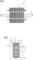
- a previously known, exemplified winding system according to FIG 2 has in a slot 8 conductors 10 each with partial conductors 9, in which case there is a two-layer winding. Each layer thus has a conductor 10 with partial conductors 9, which is arranged by a slot filler 14 both to the bottom of the slot and between the two conductors 10, as well as between the top conductor and a slot sealing wedge 13.
- FIG 4 shows a more detailed representation of a sub-conductor 9 which is essentially rectangular in shape and which, viewed in cross-section, is partially covered by a sub-conductor insulation 15 .
- the partial coverage is approx. 30 to 70% of the circumference of the sub-conductor 9 - depending on the cross-sectional shape of the sub-conductor 9.
Landscapes
- Engineering & Computer Science (AREA)
- Power Engineering (AREA)
- Manufacturing & Machinery (AREA)
- Insulation, Fastening Of Motor, Generator Windings (AREA)
- Windings For Motors And Generators (AREA)
- Manufacture Of Motors, Generators (AREA)
Description
Die Erfindung betrifft eine dynamoelektrische Maschine nach dem Oberbegriff des Anspruchs 1.The invention relates to a dynamo-electric machine according to the preamble of claim 1.
Bei dynamoelektrischen Maschinen, beispielsweise Elektromotoren oder Generatoren, sind die Wicklungssysteme aus einzelnen Spulen aufgebaut. Die einzelnen Leiter der Spule sind dabei gegeneinander isoliert. Insbesondere müssen diese einzelnen Teilleiter eines Leiters eine sogenannte Windungsisolation aufweisen, die im Regelfall nur für vergleichsweise geringe Spannungen von maximal 80 V ausgelegt ist. Eine derartige Teilleiterisolation erfolgt beispielsweise durch mit auf Leiter aufgebrachtem Isolierlack und/oder (Polyester-)GlasFaser-Umspinnung.In dynamo-electric machines, such as electric motors or generators, the winding systems are made up of individual coils. The individual conductors of the coil are insulated from one another. In particular, these individual sub-conductors of a conductor must have what is known as winding insulation, which is generally only designed for comparatively low voltages of a maximum of 80 V. Such partial conductor insulation is achieved, for example, by means of insulating varnish applied to conductors and/or (polyester) glass fiber braiding.
Die Leiter sind erfahrungsgemäß aus Kupfer oder Aluminium hergestellt, wobei die Leiter mit Lack rundum isoliert sind und/oder (Polyester-)Glas-Faser-Umspinnung aufweisen. Alternativ kann der Leiter auch eine rundum-vorhandene Bandisolierung aufweisen.Experience has shown that the conductors are made of copper or aluminium, with the conductors being insulated all around with lacquer and/or having (polyester) glass fiber braiding. Alternatively, the conductor can also have tape insulation all around.
Nachteilig dabei ist, dass bei Anordnung der Teilleiter der Leiter einer Spule in der Nut sich die Windungsisolationen gegenseitig in ihrer Dicke aufsummieren und sich somit der verfügbare Kupferfüllfaktor in der Nut reduziert.The disadvantage here is that when the partial conductors of the conductors of a coil are arranged in the slot, the winding insulations add up to one another in terms of their thickness and the available copper fill factor in the slot is therefore reduced.
Aus der
Ausgehend davon liegt der Erfindung die Aufgabe zugrunde, ein Wicklungssystem für einen Stator bereitzustellen, das eine einfache Fertigung der Spulen bei gleichzeitiger Erhöhung des Kupferfüllfaktors in den Nuten des Stators gewährleistet.Proceeding from this, the invention has for its object to provide a winding system for a stator, the one simple production of the coils while increasing the copper fill factor in the slots of the stator.
Die Lösung der gestellten Aufgabe gelingt durch eine dynamoelektrische Maschine mit den Merkmalen des Anspruchs 1 oder des Anspruchs 2.The task at hand is achieved by a dynamo-electric machine having the features of claim 1 or claim 2.
Die Lösung der gestellten Aufgabe gelingt ebenso durch ein Verfahren zur Herstellung eines Stators einer dynamoelektrischen Maschine mit den in Anspruch 3 angegebenen Schritten. Erfindungsgemäß werden nun die einzelnen Teilleiter lediglich in Umfangsrichtung betrachtet partiell isoliert.The object set is also achieved by a method for producing a stator of a dynamoelectric machine with the steps specified in
Es befindet sich somit zwischen den Teilleitern eines Leiters erfindungsgemäß nur eine Isolationsschicht - also Teilleiterisolationsschicht. Blanke Seiten eines angrenzenden Teilleiters liegen an isolierten Seiten der direkt benachbarten Teilleiter, so dass zwischen den einzelnen Teilleitern immer eine Mindestisolation gegeben ist.Thus, according to the invention, there is only one insulation layer between the sub-conductors of a conductor—that is, sub-conductor insulation layer. Bare sides of an adjacent sub-conductor lie on insulated sides of the directly adjacent sub-conductor, so that there is always a minimum insulation between the individual sub-conductors.
Bei radial übereinander angeordneten Teilleitern in einer Nut eines Stators liegt somit jeweils eine blanke Seite eines zweiten Teilleiters auf einer Isolierung eines ersten Teilleiters usw., so dass auch hier zwischen den einzelnen Teilleitern immer eine Mindestisolation gegeben ist.In the case of partial conductors arranged radially one above the other in a slot of a stator, a bare side of a second partial conductor lies on insulation of a first partial conductor, etc., so that here too there is always a minimum insulation between the individual partial conductors.
Das Wicklungssystem des Stators weist aber weiterhin grundsätzlich eine Hauptisolation auf.However, the winding system of the stator still has a main insulation.
Erfindungsgemäß sind vor allem bei einer radialen Anordnung dieser Teilleiter in der Nut und bei einem rechteckigen Querschnitt dieser Teilleiter lediglich die Oberseite oder die Unterseite der Teilleiter mit einer Isolierung zu versehen. Die Isolierung der Teilleiter erfolgt als Bandisolierung oder als Lackisolierung.According to the invention, primarily with a radial arrangement of these conductor elements in the groove and with a rectangular cross section of these conductor elements, only the upper side or the underside of the conductor elements are to be provided with insulation. The partial conductors are insulated as strip insulation or as varnish insulation.
Erfindungsgemäß ist diese Isolierung der Teilleiter noch über die angrenzenden Kantenradien dieser bedeckten Seiten der Teilleiter gezogen ist. Damit ist - im Querschnitt betrachtet - eine Seite des Teilleiters unbedeckt, eine Seite bedeckt und zwei Seiten jeweils zum Teil bedeckt.According to the invention, this insulation of the sub-conductors is still drawn over the adjoining edge radii of these covered sides of the sub-conductors. Thus, viewed in cross section, one side of the partial conductor is uncovered, one side is covered and two sides are each partially covered.
Durch die erfindungsgemäße Ausgestaltung der Teilleiterisolierung reduziert sich das notwendige Volumen der Isolierung in der Nut bei gleichzeitiger Erhöhung des Kupferfüllfaktors oder Aluminiumfüllfaktors also der elektrisch verfügbare Leitungsquerschnitt.The design of the partial conductor insulation according to the invention reduces the volume of insulation required in the slot while at the same time increasing the copper fill factor or aluminum fill factor, ie the electrically available line cross section.
Die Teilleiter weisen im Querschnitt betrachtet in der Nut, nur eine teilweise Bedeckung durch die Teilleiterisolierung auf. Die Teilbedeckung beträgt ca. 30 bis 70 % des Umfangs des Teilleiters - je nach Querschnittsform des Teilleiters. Grundsätzlich weisen die Teilleiter einen vergleichsweise gut "stapelbaren" Querschnitt auf, es wird dabei vor allem eine im Wesentlichen rechteckförmige oder quadratische Querschnittsfläche der Teilleiter verwendet werden.Viewed in cross section, the strands in the slot are only partially covered by the strand insulation. The partial coverage is approx. 30 to 70% of the circumference of the sub-conductor - depending on the cross-sectional shape of the sub-conductor. In principle, the sub-conductors have a cross section that can be "stacked" comparatively well; in particular, a substantially rectangular or square cross-sectional area of the sub-conductors is used in this case.
Dabei sind die Kanten der Teilleiter abgerundet, um die Teilleiterisolation nicht zu beschädigen.The edges of the sub-conductors are rounded so as not to damage the sub-conductor insulation.
Innerhalb einer Nut sind die Teilleitern eines Leiters radial bzw. vertikal , oder vertikal und horizontal angeordnet. Als radial wird dabei die Anordnung der Teilleiter von einem Nutgrund in Richtung Luftspalt einer dynamoelektrischen Maschine verstanden. Während unter einer horizontalen Anordnung der Teilleiter eine bzgl. des Luftspaltes im Wesentlichen tangentiale Anordnung verstanden wird.Within a slot, the partial conductors of a conductor are arranged radially or vertically, or vertically and horizontally. The arrangement of the sub-conductors from a slot base in the direction of the air gap of a dynamoelectric machine is understood to be radial. A horizontal arrangement of the sub-conductors means an arrangement that is essentially tangential with respect to the air gap.
Bei Teilleitern mit rechteckiger Querschnittsform und insbesondere radialer Anordnung in einer Nut, bei der die Schmalseiten der Teilleiter aneinandergrenzen, wird die Teilbedeckung geringer sein, als bei einer Ausführung wo die Längsseiten eines rechteckförmigen Teilleiters über einander liegen.In the case of strands with a rectangular cross-section and, in particular, a radial arrangement in a slot, in which the narrow sides of the strands adjoin one another, the partial coverage will be less than in an embodiment where the long sides of a rectangular sub-conductor lie on top of each other.
Axial außerhalb der Nut, also im Bereich des Wickelkopfes kann die Bedeckung und/oder die Anordnung der Teilleiter des Leiters wie in der Nut ausgeführt sein.Axially outside the slot, ie in the area of the end winding, the covering and/or the arrangement of the partial conductors of the conductor can be designed as in the slot.
Aufgrund des, je nach Maschinentyp ausgeführten Wickelkopfdesigns kann es notwendig sein im Wickelkopfbereich den Bedeckungsgrad zu ändern.Due to the design of the winding head, depending on the machine type, it may be necessary to change the degree of coverage in the winding head area.
Die Isolation der Teilleiter ist Abdeckung vorzugsweise eine Folie, insbesondere aus Polyimid, die mit einem (Schmelz-) Kleber, z.B. FEP (Fluorethylen-Propylen)versehen ist und an den Teilleitern positioniert, insbesondere verklebt ist.The insulation of the sub-conductors is a cover, preferably a film, in particular made of polyimide, which is provided with a (hot-melt) adhesive, e.g. FEP (fluoroethylene-propylene) and is positioned, in particular glued, on the sub-conductors.
Die Abdeckung, insbesondere die Folie ist dabei koronabeständig ausgeführt, was beispielsweise durch dementsprechende Einlagerung geeigneter Partikel erfolgt.The cover, in particular the film, is designed to be corona-resistant, which is achieved, for example, by the corresponding incorporation of suitable particles.
Die Erfindung sowie vorteilhafte Ausgestaltungen der Erfindung werden anhand eines Ausführungsbeispiels näher erläutert. Darin zeigt:
- FIG 1
- eine prinzipielle dynamoelektrische Maschine,
- FIG 2
- einen Nutquerschnitt einer Hochspannungsisolierung,
- FIG 3
- eine Spule mit einzelnen Teilleitern,
- FIG 4
- eine Detaildarstellung eines Teilleiters,
- FIG 5
- eine weitere Spule mit Teilleitern.
- FIG 1
- a principle dynamo-electric machine,
- FIG 2
- a groove cross-section of a high-voltage insulation,
- 3
- a coil with individual strands,
- FIG 4
- a detailed representation of a sub-conductor,
- 5
- another coil with partial conductors.
Dem Luftspalt 20 zugewandt befindet sich im Stator 5 ein in nicht näher dargestellten Nuten angeordnetes Wicklungssystem, das an den Stirnseiten des Stators 5 Wickelköpfe 3 ausbildet.Facing the
Ein bisher bekanntes, beispielhaft dargestelltes Wicklungssystem gemäß
Jeder Teilleiter 9 weist dabei eine ihn umgebende Teilleiterisolierung 15 auf, die die vorhandene Windungsisolation übernimmt und die bei Hochspannungsmaschinen im Bereich von ca. 80 bis 100 V liegt. Jeder Leiter 10 ist von einer Hauptisolierung 11 umgeben, wobei das gesamte Wicklungssystem in dieser Nut 8 von einer Nutisolation 11 gegenüber dem Blechpaket des Stators 5 ebenfalls isoliert ist.Each
Durch den beschriebenen Aufbau weist jede Teilleiterisolierung 15 Schichtdicken auf, die sich über die radiale Höhe des Leiters 10 in der Nut 8 summieren und so zu einem reduzierten Kupferfüllfaktor des Wicklungssystems innerhalb der Nut führen.Due to the structure described, each
Erfindungsgemäß wird nunmehr gemäß
Mit anderen Worten: bei Teilleitern 9 mit rechteckiger Querschnittsform und insbesondere radialer Anordnung in der Nut 8, bei der die Schmalseiten der Teilleiter 9 aneinandergrenzen, wird die Teilbedeckung geringer sein, als bei der Ausführung gemäß
Die Isolation an den Teilleitern 9 ist vorzugsweise eine Folie, insbesondere aus Polyimid, die mit einem (Schmelz-) Kleber, z.B. FEP (Fluorethylen-Propylen)versehen ist und an den Teilleitern 9 positioniert, insbesondere verklebt ist.The insulation on the
Grundsätzlich weisen die Teilleiter 9 eine im Wesentlichen rechteckförmige oder quadratische Querschnittsfläche auf. Dabei sind die Kanten der Teilleiter 9 abgerundet, um die Teilleiterisolation 15 nicht zu beschädigen. Innerhalb einer Nut 8 sind die Teilleitern 9 eines Leiters 10 radial bzw. vertikal, oder vertikal und horizontal angeordnet.In principle, the
Der erfindungsgemäße Gedanke ist für Einschicht-, Zweischicht-, oder Mehrschichtwicklungen im Stator 5 geeignet. förmigen Teilleiters 9 mit einer Teilleiterisolierung 15 versehen. Die an diese Teilleiterisolierung 15 angrenzenden Teilleiter 9 weisen auf diesen Seiten erfindungsgemäß keine Teilleiterisolierung 15 auf. Es ist jedoch - wie beispielsweise in
Der erfindungsgemäße Gedanke ist für Einschicht-, Zweischicht-, oder Mehrschichtwicklungen im Stator 5 geeignet.The idea according to the invention is suitable for single-layer, two-layer or multi-layer windings in the
Claims (3)
- Dynamo-electric machine (1) comprising a stator (5) and a rotor (6) and comprising a winding system (3) which is arranged in slots (8) of the stator (5) and which has individual mutually electrically contactable coils for each phase, wherein each conductor (10) of the coil is built up from a plurality of sub-conductors/windings, wherein these sub-conductors (9) are insulated from one another in that the sub-conductors (9) have only one insulating layer (15) relative to the adjacent sub-conductor or conductors (9) of its conductor (10) of the respective slot (8), wherein the sub-conductors (9) have a substantially rectangular or square cross-sectional area, wherein the insulating layer (15) is either a film stuck onto the sub-conductor (9) or a varnish insulation, wherein each conductor (10) is surrounded by a main insulation (11), characterized in that the edges of the sub-conductors (9) are rounded and in thatwhen the sub-conductors (9) are arranged only radially above one another, the sub-conductors (9) are covered only by a single-sided insulating layer (15), which reaches over the adjacent edge radii of the side covered by the insulating layer (15), andwhen the sub-conductors (9) are arranged radially and horizontally above and beside one another, the sub-conductors (9) are covered only by a two-sided insulating layer (15), which can also reach over the adjacent edge radii of the sides covered by the insulating layer (15).
- Dynamo-electric machine according to Claim 1, characterized in that the coverage of the sub-conductor (9) by the insulating layer, viewed in cross section, is between 30 and 70%.
- Method for producing a stator (5) of a dynamo-electric machine (1) according to Claim 1,
characterized by the following steps:- providing a sub-conductor (9) described in Claim 1, wherein the sub-conductors (9) have a substantially rectangular or square cross-sectional area, the edges of which are rounded,- partially applying an insulating layer (15) to the sub-conductor (9), in particular with a predefinable coverage of the cross section of 30 to 70%, wherein the insulating layer (15) is either a film stuck onto the sub-conductor (9) or a varnish insulation,- arranging the sub-conductors (9) of a conductor (10) in such a way that there is only one insulating layer (15) between the adjacent sub-conductor or sub-conductors (9) of the conductor (10),- inserting the sub-conductors (9) described in Claim 1 of a conductor (10) of a coil only radially above one another or radially and horizontally above and beside one another into the slot (8) of a stator (5) of a dynamo-electric machine (1), wherein each conductor (10) is surrounded by a main insulation (11).
Applications Claiming Priority (2)
| Application Number | Priority Date | Filing Date | Title |
|---|---|---|---|
| EP17208914.6A EP3503354A1 (en) | 2017-12-20 | 2017-12-20 | Isolation of sub-conductors of a dynamoelectric machine |
| PCT/EP2018/084666 WO2019121279A1 (en) | 2017-12-20 | 2018-12-13 | Insulation of sub-conductors of a dynamo-electric machine |
Publications (2)
| Publication Number | Publication Date |
|---|---|
| EP3688862A1 EP3688862A1 (en) | 2020-08-05 |
| EP3688862B1 true EP3688862B1 (en) | 2022-10-12 |
Family
ID=60702365
Family Applications (4)
| Application Number | Title | Priority Date | Filing Date |
|---|---|---|---|
| EP17208914.6A Withdrawn EP3503354A1 (en) | 2017-12-20 | 2017-12-20 | Isolation of sub-conductors of a dynamoelectric machine |
| EP18163675.4A Withdrawn EP3503353A1 (en) | 2017-12-20 | 2018-03-23 | Isolation of sub-conductors of a dynamoelectric machine |
| EP18830180.8A Active EP3688862B1 (en) | 2017-12-20 | 2018-12-13 | Isolation of sub-conductors of a dynamoelectric machine |
| EP18830181.6A Active EP3871319B1 (en) | 2017-12-20 | 2018-12-13 | Isolation of sub-conductors of a dynamoelectric machine |
Family Applications Before (2)
| Application Number | Title | Priority Date | Filing Date |
|---|---|---|---|
| EP17208914.6A Withdrawn EP3503354A1 (en) | 2017-12-20 | 2017-12-20 | Isolation of sub-conductors of a dynamoelectric machine |
| EP18163675.4A Withdrawn EP3503353A1 (en) | 2017-12-20 | 2018-03-23 | Isolation of sub-conductors of a dynamoelectric machine |
Family Applications After (1)
| Application Number | Title | Priority Date | Filing Date |
|---|---|---|---|
| EP18830181.6A Active EP3871319B1 (en) | 2017-12-20 | 2018-12-13 | Isolation of sub-conductors of a dynamoelectric machine |
Country Status (6)
| Country | Link |
|---|---|
| US (1) | US20200336035A1 (en) |
| EP (4) | EP3503354A1 (en) |
| CN (2) | CN212486231U (en) |
| DK (1) | DK3871319T3 (en) |
| ES (2) | ES2928881T3 (en) |
| WO (2) | WO2019121280A1 (en) |
Families Citing this family (4)
| Publication number | Priority date | Publication date | Assignee | Title |
|---|---|---|---|---|
| EP3879545A1 (en) * | 2020-03-12 | 2021-09-15 | ABB Schweiz AG | Insulated winding for an electromagnetic device |
| EP3958443A1 (en) * | 2020-08-20 | 2022-02-23 | ATOP S.p.A. | Stator, apparatus and method for preparing a pre-shaped insulator |
| DE102021109899A1 (en) | 2021-04-20 | 2022-10-20 | Bayerische Motoren Werke Aktiengesellschaft | Rotor and method for manufacturing a rotor |
| EP4451522A1 (en) * | 2023-04-17 | 2024-10-23 | Hamilton Sundstrand Corporation | Stator coil insulation |
Citations (1)
| Publication number | Priority date | Publication date | Assignee | Title |
|---|---|---|---|---|
| FR397892A (en) * | 1908-07-03 | 1909-05-19 | Bbc Brown Boveri & Cie | Insulation mode of electrical conductors |
Family Cites Families (17)
| Publication number | Priority date | Publication date | Assignee | Title |
|---|---|---|---|---|
| DE271686C (en) * | ||||
| US1118446A (en) * | 1912-09-17 | 1914-11-24 | Gen Electric | Insulating-coil. |
| DE1056722B (en) * | 1955-09-29 | 1959-05-06 | Siemens Ag | Overvoltage-proof winding insulation for electrical high-voltage machines |
| FR1534678A (en) * | 1965-12-31 | 1968-08-02 | Merlin Gerin | Inductance coil |
| JPH04125910A (en) * | 1990-09-18 | 1992-04-27 | Toshiba Corp | Interlayer insulating structure of propulsion |
| WO1997030506A1 (en) * | 1996-02-16 | 1997-08-21 | Hitachi, Ltd. | Stator winding of rotating electric machine and its manufacturing method |
| JP2001145286A (en) * | 1999-11-12 | 2001-05-25 | Mitsubishi Electric Corp | Stator of rotating electric machine and method of manufacturing the same |
| CN1581380A (en) * | 2003-08-11 | 2005-02-16 | 尼克桑斯公司 | Glass fiber silk screen tape commutating conducting wire, and its manufacture and use method |
| JP4878002B2 (en) * | 2006-07-06 | 2012-02-15 | 株式会社日本自動車部品総合研究所 | Electromagnetic equipment |
| CH699023B1 (en) * | 2007-01-18 | 2010-01-15 | Alstom Technology Ltd | Conductor bar for the stator of a generator as well as methods for its production. |
| JP2008193860A (en) * | 2007-02-07 | 2008-08-21 | Mitsubishi Cable Ind Ltd | Collective conductor and its manufacturing method |
| CN100525012C (en) * | 2007-06-15 | 2009-08-05 | 江苏安捷机电技术有限公司 | Insulating system with double-strength, zero-air-gap and corona resistance for electric motor of non-gear permanent-magnetic tractor |
| CN103493341B (en) * | 2011-04-18 | 2016-11-23 | 三菱电机株式会社 | Rotary machine coil and manufacture method thereof |
| US8978239B2 (en) * | 2013-01-09 | 2015-03-17 | General Electric Company | Field coil winding assembly |
| JP6325549B2 (en) * | 2013-09-06 | 2018-05-16 | 古河電気工業株式会社 | Flat electric wire, method for manufacturing the same, and electrical equipment |
| CN104092324A (en) * | 2014-07-21 | 2014-10-08 | 苏州贯龙电磁线股份有限公司 | Double-insulation electromagnetic wire for wind turbine generator |
| CN206441553U (en) * | 2017-02-17 | 2017-08-25 | 上海同立电工材料有限公司 | A kind of wire insulation mica tape |
-
2017
- 2017-12-20 EP EP17208914.6A patent/EP3503354A1/en not_active Withdrawn
-
2018
- 2018-03-23 EP EP18163675.4A patent/EP3503353A1/en not_active Withdrawn
- 2018-12-13 DK DK18830181.6T patent/DK3871319T3/en active
- 2018-12-13 WO PCT/EP2018/084667 patent/WO2019121280A1/en active Application Filing
- 2018-12-13 CN CN201890001383.6U patent/CN212486231U/en active Active
- 2018-12-13 ES ES18830180T patent/ES2928881T3/en active Active
- 2018-12-13 ES ES18830181T patent/ES2925475T3/en active Active
- 2018-12-13 EP EP18830180.8A patent/EP3688862B1/en active Active
- 2018-12-13 CN CN201880082664.3A patent/CN111512520B/en active Active
- 2018-12-13 EP EP18830181.6A patent/EP3871319B1/en active Active
- 2018-12-13 WO PCT/EP2018/084666 patent/WO2019121279A1/en active Search and Examination
- 2018-12-13 US US16/956,279 patent/US20200336035A1/en not_active Abandoned
Patent Citations (1)
| Publication number | Priority date | Publication date | Assignee | Title |
|---|---|---|---|---|
| FR397892A (en) * | 1908-07-03 | 1909-05-19 | Bbc Brown Boveri & Cie | Insulation mode of electrical conductors |
Also Published As
| Publication number | Publication date |
|---|---|
| DK3871319T3 (en) | 2022-10-03 |
| EP3503353A1 (en) | 2019-06-26 |
| ES2925475T3 (en) | 2022-10-18 |
| EP3688862A1 (en) | 2020-08-05 |
| EP3871319A1 (en) | 2021-09-01 |
| CN111512520B (en) | 2023-04-04 |
| CN111512520A (en) | 2020-08-07 |
| US20200336035A1 (en) | 2020-10-22 |
| ES2928881T3 (en) | 2022-11-23 |
| WO2019121280A1 (en) | 2019-06-27 |
| EP3503354A1 (en) | 2019-06-26 |
| EP3871319B1 (en) | 2022-07-20 |
| WO2019121279A1 (en) | 2019-06-27 |
| CN212486231U (en) | 2021-02-05 |
Similar Documents
| Publication | Publication Date | Title |
|---|---|---|
| EP3688862B1 (en) | Isolation of sub-conductors of a dynamoelectric machine | |
| DE60023421T2 (en) | Winding for a stator and method for its manufacture | |
| DE102009032882B3 (en) | Method for producing preformed coil for floor winding of dynamo-electric machine using raw coil, involves bending longitudinal sides around specific degrees such that end winding sides are bent at angle from longitudinal sides | |
| AT521301B1 (en) | Stator with insulation layer | |
| DE112014004639B4 (en) | Rotating electrical machine and manufacturing process therefor | |
| WO2018007071A1 (en) | Water-cooled generator strip having a cooling channel gap space | |
| DE112015002276B4 (en) | Rotating electrical machine and manufacturing process therefor | |
| DE112015007072T5 (en) | Electric rotary machine | |
| DE112013004722T5 (en) | Electric machine | |
| EP1060485B1 (en) | Multiple parallel conductor for electrical machines and devices | |
| EP3335301B1 (en) | Stator of an electric machine | |
| DE102019109516A1 (en) | Winding and method of making a winding | |
| WO2010006670A1 (en) | Winding for a transformer | |
| DE112015004183T5 (en) | Stator with a good wedge holder with optimized magnetic circuit and method for electrical insulation of such a stator | |
| DE102017218451A1 (en) | Stator and electric machine with stator | |
| EP3218993B1 (en) | Stator for electric machine | |
| DE102013212909A1 (en) | Machine component for a multi-winding electrical machine | |
| WO2000042695A1 (en) | Electrical conductor, turbogenerator and method for producing a corona shield for an electrical conductor | |
| DE69401637T2 (en) | Improved stand for a two-phase electrical machine | |
| EP2905875A1 (en) | Main element of an electric machine | |
| AT524330B1 (en) | Machine component for an electrical machine | |
| DE102017208150A1 (en) | electric motor | |
| DE102016209523A1 (en) | Stator of an electrical machine with a connection device for stator coils and electrical machine with such a stator | |
| EP3555994B1 (en) | Stator for an eletric machine and method of manufacturing this stator | |
| EP0932241A2 (en) | Process for manufacturing bar conductors |
Legal Events
| Date | Code | Title | Description |
|---|---|---|---|
| STAA | Information on the status of an ep patent application or granted ep patent |
Free format text: STATUS: UNKNOWN |
|
| STAA | Information on the status of an ep patent application or granted ep patent |
Free format text: STATUS: THE INTERNATIONAL PUBLICATION HAS BEEN MADE |
|
| PUAI | Public reference made under article 153(3) epc to a published international application that has entered the european phase |
Free format text: ORIGINAL CODE: 0009012 |
|
| STAA | Information on the status of an ep patent application or granted ep patent |
Free format text: STATUS: REQUEST FOR EXAMINATION WAS MADE |
|
| 17P | Request for examination filed |
Effective date: 20200427 |
|
| AK | Designated contracting states |
Kind code of ref document: A1 Designated state(s): AL AT BE BG CH CY CZ DE DK EE ES FI FR GB GR HR HU IE IS IT LI LT LU LV MC MK MT NL NO PL PT RO RS SE SI SK SM TR |
|
| AX | Request for extension of the european patent |
Extension state: BA ME |
|
| RIN1 | Information on inventor provided before grant (corrected) |
Inventor name: LUETKE, HARRY Inventor name: SCHOENBAUER, NORBERT Inventor name: BRENNER, ROBIN |
|
| RAP1 | Party data changed (applicant data changed or rights of an application transferred) |
Owner name: FLENDER GMBH |
|
| STAA | Information on the status of an ep patent application or granted ep patent |
Free format text: STATUS: EXAMINATION IS IN PROGRESS |
|
| STAA | Information on the status of an ep patent application or granted ep patent |
Free format text: STATUS: EXAMINATION IS IN PROGRESS |
|
| 17Q | First examination report despatched |
Effective date: 20210125 |
|
| DAV | Request for validation of the european patent (deleted) | ||
| DAX | Request for extension of the european patent (deleted) | ||
| GRAP | Despatch of communication of intention to grant a patent |
Free format text: ORIGINAL CODE: EPIDOSNIGR1 |
|
| STAA | Information on the status of an ep patent application or granted ep patent |
Free format text: STATUS: GRANT OF PATENT IS INTENDED |
|
| RIC1 | Information provided on ipc code assigned before grant |
Ipc: H01F 27/32 20060101ALN20220630BHEP Ipc: H02K 15/10 20060101ALI20220630BHEP Ipc: H02K 3/30 20060101ALI20220630BHEP Ipc: H02K 3/34 20060101AFI20220630BHEP |
|
| INTG | Intention to grant announced |
Effective date: 20220715 |
|
| GRAS | Grant fee paid |
Free format text: ORIGINAL CODE: EPIDOSNIGR3 |
|
| GRAA | (expected) grant |
Free format text: ORIGINAL CODE: 0009210 |
|
| STAA | Information on the status of an ep patent application or granted ep patent |
Free format text: STATUS: THE PATENT HAS BEEN GRANTED |
|
| AK | Designated contracting states |
Kind code of ref document: B1 Designated state(s): AL AT BE BG CH CY CZ DE DK EE ES FI FR GB GR HR HU IE IS IT LI LT LU LV MC MK MT NL NO PL PT RO RS SE SI SK SM TR |
|
| REG | Reference to a national code |
Ref country code: GB Ref legal event code: FG4D Free format text: NOT ENGLISH |
|
| REG | Reference to a national code |
Ref country code: CH Ref legal event code: EP |
|
| REG | Reference to a national code |
Ref country code: DE Ref legal event code: R096 Ref document number: 502018010841 Country of ref document: DE |
|
| REG | Reference to a national code |
Ref country code: IE Ref legal event code: FG4D Free format text: LANGUAGE OF EP DOCUMENT: GERMAN |
|
| REG | Reference to a national code |
Ref country code: AT Ref legal event code: REF Ref document number: 1524758 Country of ref document: AT Kind code of ref document: T Effective date: 20221115 |
|
| REG | Reference to a national code |
Ref country code: ES Ref legal event code: FG2A Ref document number: 2928881 Country of ref document: ES Kind code of ref document: T3 Effective date: 20221123 |
|
| PGFP | Annual fee paid to national office [announced via postgrant information from national office to epo] |
Ref country code: GB Payment date: 20221223 Year of fee payment: 5 Ref country code: FR Payment date: 20221222 Year of fee payment: 5 |
|
| REG | Reference to a national code |
Ref country code: LT Ref legal event code: MG9D |
|
| REG | Reference to a national code |
Ref country code: NL Ref legal event code: MP Effective date: 20221012 |
|
| PG25 | Lapsed in a contracting state [announced via postgrant information from national office to epo] |
Ref country code: NL Free format text: LAPSE BECAUSE OF FAILURE TO SUBMIT A TRANSLATION OF THE DESCRIPTION OR TO PAY THE FEE WITHIN THE PRESCRIBED TIME-LIMIT Effective date: 20221012 |
|
| PG25 | Lapsed in a contracting state [announced via postgrant information from national office to epo] |
Ref country code: SE Free format text: LAPSE BECAUSE OF FAILURE TO SUBMIT A TRANSLATION OF THE DESCRIPTION OR TO PAY THE FEE WITHIN THE PRESCRIBED TIME-LIMIT Effective date: 20221012 Ref country code: PT Free format text: LAPSE BECAUSE OF FAILURE TO SUBMIT A TRANSLATION OF THE DESCRIPTION OR TO PAY THE FEE WITHIN THE PRESCRIBED TIME-LIMIT Effective date: 20230213 Ref country code: NO Free format text: LAPSE BECAUSE OF FAILURE TO SUBMIT A TRANSLATION OF THE DESCRIPTION OR TO PAY THE FEE WITHIN THE PRESCRIBED TIME-LIMIT Effective date: 20230112 Ref country code: LT Free format text: LAPSE BECAUSE OF FAILURE TO SUBMIT A TRANSLATION OF THE DESCRIPTION OR TO PAY THE FEE WITHIN THE PRESCRIBED TIME-LIMIT Effective date: 20221012 Ref country code: FI Free format text: LAPSE BECAUSE OF FAILURE TO SUBMIT A TRANSLATION OF THE DESCRIPTION OR TO PAY THE FEE WITHIN THE PRESCRIBED TIME-LIMIT Effective date: 20221012 |
|
| PGFP | Annual fee paid to national office [announced via postgrant information from national office to epo] |
Ref country code: ES Payment date: 20230228 Year of fee payment: 5 |
|
| PG25 | Lapsed in a contracting state [announced via postgrant information from national office to epo] |
Ref country code: RS Free format text: LAPSE BECAUSE OF FAILURE TO SUBMIT A TRANSLATION OF THE DESCRIPTION OR TO PAY THE FEE WITHIN THE PRESCRIBED TIME-LIMIT Effective date: 20221012 Ref country code: PL Free format text: LAPSE BECAUSE OF FAILURE TO SUBMIT A TRANSLATION OF THE DESCRIPTION OR TO PAY THE FEE WITHIN THE PRESCRIBED TIME-LIMIT Effective date: 20221012 Ref country code: LV Free format text: LAPSE BECAUSE OF FAILURE TO SUBMIT A TRANSLATION OF THE DESCRIPTION OR TO PAY THE FEE WITHIN THE PRESCRIBED TIME-LIMIT Effective date: 20221012 Ref country code: IS Free format text: LAPSE BECAUSE OF FAILURE TO SUBMIT A TRANSLATION OF THE DESCRIPTION OR TO PAY THE FEE WITHIN THE PRESCRIBED TIME-LIMIT Effective date: 20230212 Ref country code: HR Free format text: LAPSE BECAUSE OF FAILURE TO SUBMIT A TRANSLATION OF THE DESCRIPTION OR TO PAY THE FEE WITHIN THE PRESCRIBED TIME-LIMIT Effective date: 20221012 Ref country code: GR Free format text: LAPSE BECAUSE OF FAILURE TO SUBMIT A TRANSLATION OF THE DESCRIPTION OR TO PAY THE FEE WITHIN THE PRESCRIBED TIME-LIMIT Effective date: 20230113 |
|
| REG | Reference to a national code |
Ref country code: DE Ref legal event code: R097 Ref document number: 502018010841 Country of ref document: DE |
|
| PG25 | Lapsed in a contracting state [announced via postgrant information from national office to epo] |
Ref country code: SM Free format text: LAPSE BECAUSE OF FAILURE TO SUBMIT A TRANSLATION OF THE DESCRIPTION OR TO PAY THE FEE WITHIN THE PRESCRIBED TIME-LIMIT Effective date: 20221012 Ref country code: RO Free format text: LAPSE BECAUSE OF FAILURE TO SUBMIT A TRANSLATION OF THE DESCRIPTION OR TO PAY THE FEE WITHIN THE PRESCRIBED TIME-LIMIT Effective date: 20221012 Ref country code: EE Free format text: LAPSE BECAUSE OF FAILURE TO SUBMIT A TRANSLATION OF THE DESCRIPTION OR TO PAY THE FEE WITHIN THE PRESCRIBED TIME-LIMIT Effective date: 20221012 Ref country code: DK Free format text: LAPSE BECAUSE OF FAILURE TO SUBMIT A TRANSLATION OF THE DESCRIPTION OR TO PAY THE FEE WITHIN THE PRESCRIBED TIME-LIMIT Effective date: 20221012 Ref country code: CZ Free format text: LAPSE BECAUSE OF FAILURE TO SUBMIT A TRANSLATION OF THE DESCRIPTION OR TO PAY THE FEE WITHIN THE PRESCRIBED TIME-LIMIT Effective date: 20221012 |
|
| REG | Reference to a national code |
Ref country code: CH Ref legal event code: PL |
|
| PLBE | No opposition filed within time limit |
Free format text: ORIGINAL CODE: 0009261 |
|
| STAA | Information on the status of an ep patent application or granted ep patent |
Free format text: STATUS: NO OPPOSITION FILED WITHIN TIME LIMIT |
|
| REG | Reference to a national code |
Ref country code: BE Ref legal event code: MM Effective date: 20221231 |
|
| PG25 | Lapsed in a contracting state [announced via postgrant information from national office to epo] |
Ref country code: SK Free format text: LAPSE BECAUSE OF FAILURE TO SUBMIT A TRANSLATION OF THE DESCRIPTION OR TO PAY THE FEE WITHIN THE PRESCRIBED TIME-LIMIT Effective date: 20221012 Ref country code: LU Free format text: LAPSE BECAUSE OF NON-PAYMENT OF DUE FEES Effective date: 20221213 Ref country code: AL Free format text: LAPSE BECAUSE OF FAILURE TO SUBMIT A TRANSLATION OF THE DESCRIPTION OR TO PAY THE FEE WITHIN THE PRESCRIBED TIME-LIMIT Effective date: 20221012 |
|
| 26N | No opposition filed |
Effective date: 20230713 |
|
| PG25 | Lapsed in a contracting state [announced via postgrant information from national office to epo] |
Ref country code: LI Free format text: LAPSE BECAUSE OF NON-PAYMENT OF DUE FEES Effective date: 20221231 Ref country code: IE Free format text: LAPSE BECAUSE OF NON-PAYMENT OF DUE FEES Effective date: 20221213 Ref country code: CH Free format text: LAPSE BECAUSE OF NON-PAYMENT OF DUE FEES Effective date: 20221231 |
|
| PG25 | Lapsed in a contracting state [announced via postgrant information from national office to epo] |
Ref country code: SI Free format text: LAPSE BECAUSE OF FAILURE TO SUBMIT A TRANSLATION OF THE DESCRIPTION OR TO PAY THE FEE WITHIN THE PRESCRIBED TIME-LIMIT Effective date: 20221012 Ref country code: BE Free format text: LAPSE BECAUSE OF NON-PAYMENT OF DUE FEES Effective date: 20221231 |
|
| PGFP | Annual fee paid to national office [announced via postgrant information from national office to epo] |
Ref country code: DE Payment date: 20231214 Year of fee payment: 6 |
|
| PG25 | Lapsed in a contracting state [announced via postgrant information from national office to epo] |
Ref country code: HU Free format text: LAPSE BECAUSE OF FAILURE TO SUBMIT A TRANSLATION OF THE DESCRIPTION OR TO PAY THE FEE WITHIN THE PRESCRIBED TIME-LIMIT; INVALID AB INITIO Effective date: 20181213 |
|
| PG25 | Lapsed in a contracting state [announced via postgrant information from national office to epo] |
Ref country code: CY Free format text: LAPSE BECAUSE OF FAILURE TO SUBMIT A TRANSLATION OF THE DESCRIPTION OR TO PAY THE FEE WITHIN THE PRESCRIBED TIME-LIMIT Effective date: 20221012 |
|
| PG25 | Lapsed in a contracting state [announced via postgrant information from national office to epo] |
Ref country code: MK Free format text: LAPSE BECAUSE OF FAILURE TO SUBMIT A TRANSLATION OF THE DESCRIPTION OR TO PAY THE FEE WITHIN THE PRESCRIBED TIME-LIMIT Effective date: 20221012 Ref country code: IT Free format text: LAPSE BECAUSE OF FAILURE TO SUBMIT A TRANSLATION OF THE DESCRIPTION OR TO PAY THE FEE WITHIN THE PRESCRIBED TIME-LIMIT Effective date: 20221012 |
|
| PG25 | Lapsed in a contracting state [announced via postgrant information from national office to epo] |
Ref country code: MC Free format text: LAPSE BECAUSE OF FAILURE TO SUBMIT A TRANSLATION OF THE DESCRIPTION OR TO PAY THE FEE WITHIN THE PRESCRIBED TIME-LIMIT Effective date: 20221012 |
|
| PG25 | Lapsed in a contracting state [announced via postgrant information from national office to epo] |
Ref country code: MC Free format text: LAPSE BECAUSE OF FAILURE TO SUBMIT A TRANSLATION OF THE DESCRIPTION OR TO PAY THE FEE WITHIN THE PRESCRIBED TIME-LIMIT Effective date: 20221012 |
|
| PG25 | Lapsed in a contracting state [announced via postgrant information from national office to epo] |
Ref country code: BG Free format text: LAPSE BECAUSE OF FAILURE TO SUBMIT A TRANSLATION OF THE DESCRIPTION OR TO PAY THE FEE WITHIN THE PRESCRIBED TIME-LIMIT Effective date: 20221012 |
|
| GBPC | Gb: european patent ceased through non-payment of renewal fee |
Effective date: 20231213 |
|
| PG25 | Lapsed in a contracting state [announced via postgrant information from national office to epo] |
Ref country code: MT Free format text: LAPSE BECAUSE OF FAILURE TO SUBMIT A TRANSLATION OF THE DESCRIPTION OR TO PAY THE FEE WITHIN THE PRESCRIBED TIME-LIMIT Effective date: 20221012 |
|
| PG25 | Lapsed in a contracting state [announced via postgrant information from national office to epo] |
Ref country code: GB Free format text: LAPSE BECAUSE OF NON-PAYMENT OF DUE FEES Effective date: 20231213 |
|
| PG25 | Lapsed in a contracting state [announced via postgrant information from national office to epo] |
Ref country code: FR Free format text: LAPSE BECAUSE OF NON-PAYMENT OF DUE FEES Effective date: 20231231 |