EP3688361B1 - Fluid handling devices - Google Patents
Fluid handling devices Download PDFInfo
- Publication number
- EP3688361B1 EP3688361B1 EP18860563.8A EP18860563A EP3688361B1 EP 3688361 B1 EP3688361 B1 EP 3688361B1 EP 18860563 A EP18860563 A EP 18860563A EP 3688361 B1 EP3688361 B1 EP 3688361B1
- Authority
- EP
- European Patent Office
- Prior art keywords
- body portion
- fluid handling
- spillage
- handling device
- core member
- Prior art date
- Legal status (The legal status is an assumption and is not a legal conclusion. Google has not performed a legal analysis and makes no representation as to the accuracy of the status listed.)
- Active
Links
Images










Classifications
-
- F—MECHANICAL ENGINEERING; LIGHTING; HEATING; WEAPONS; BLASTING
- F16—ENGINEERING ELEMENTS AND UNITS; GENERAL MEASURES FOR PRODUCING AND MAINTAINING EFFECTIVE FUNCTIONING OF MACHINES OR INSTALLATIONS; THERMAL INSULATION IN GENERAL
- F16K—VALVES; TAPS; COCKS; ACTUATING-FLOATS; DEVICES FOR VENTING OR AERATING
- F16K5/00—Plug valves; Taps or cocks comprising only cut-off apparatus having at least one of the sealing faces shaped as a more or less complete surface of a solid of revolution, the opening and closing movement being predominantly rotary
- F16K5/04—Plug valves; Taps or cocks comprising only cut-off apparatus having at least one of the sealing faces shaped as a more or less complete surface of a solid of revolution, the opening and closing movement being predominantly rotary with plugs having cylindrical surfaces; Packings therefor
- F16K5/0407—Plug valves; Taps or cocks comprising only cut-off apparatus having at least one of the sealing faces shaped as a more or less complete surface of a solid of revolution, the opening and closing movement being predominantly rotary with plugs having cylindrical surfaces; Packings therefor with particular plug arrangements, e.g. particular shape or built-in means
-
- A—HUMAN NECESSITIES
- A61—MEDICAL OR VETERINARY SCIENCE; HYGIENE
- A61M—DEVICES FOR INTRODUCING MEDIA INTO, OR ONTO, THE BODY; DEVICES FOR TRANSDUCING BODY MEDIA OR FOR TAKING MEDIA FROM THE BODY; DEVICES FOR PRODUCING OR ENDING SLEEP OR STUPOR
- A61M39/00—Tubes, tube connectors, tube couplings, valves, access sites or the like, specially adapted for medical use
- A61M39/10—Tube connectors; Tube couplings
- A61M39/1055—Rotating or swivel joints
-
- A—HUMAN NECESSITIES
- A61—MEDICAL OR VETERINARY SCIENCE; HYGIENE
- A61F—FILTERS IMPLANTABLE INTO BLOOD VESSELS; PROSTHESES; DEVICES PROVIDING PATENCY TO, OR PREVENTING COLLAPSING OF, TUBULAR STRUCTURES OF THE BODY, e.g. STENTS; ORTHOPAEDIC, NURSING OR CONTRACEPTIVE DEVICES; FOMENTATION; TREATMENT OR PROTECTION OF EYES OR EARS; BANDAGES, DRESSINGS OR ABSORBENT PADS; FIRST-AID KITS
- A61F5/00—Orthopaedic methods or devices for non-surgical treatment of bones or joints; Nursing devices ; Anti-rape devices
- A61F5/44—Devices worn by the patient for reception of urine, faeces, catamenial or other discharge; Colostomy devices
- A61F5/4404—Details or parts
- A61F5/4405—Valves or valve arrangements specially adapted therefor ; Fluid inlets or outlets
-
- A—HUMAN NECESSITIES
- A61—MEDICAL OR VETERINARY SCIENCE; HYGIENE
- A61M—DEVICES FOR INTRODUCING MEDIA INTO, OR ONTO, THE BODY; DEVICES FOR TRANSDUCING BODY MEDIA OR FOR TAKING MEDIA FROM THE BODY; DEVICES FOR PRODUCING OR ENDING SLEEP OR STUPOR
- A61M39/00—Tubes, tube connectors, tube couplings, valves, access sites or the like, specially adapted for medical use
- A61M39/10—Tube connectors; Tube couplings
-
- A—HUMAN NECESSITIES
- A61—MEDICAL OR VETERINARY SCIENCE; HYGIENE
- A61M—DEVICES FOR INTRODUCING MEDIA INTO, OR ONTO, THE BODY; DEVICES FOR TRANSDUCING BODY MEDIA OR FOR TAKING MEDIA FROM THE BODY; DEVICES FOR PRODUCING OR ENDING SLEEP OR STUPOR
- A61M39/00—Tubes, tube connectors, tube couplings, valves, access sites or the like, specially adapted for medical use
- A61M39/10—Tube connectors; Tube couplings
- A61M39/1011—Locking means for securing connection; Additional tamper safeties
-
- A—HUMAN NECESSITIES
- A61—MEDICAL OR VETERINARY SCIENCE; HYGIENE
- A61M—DEVICES FOR INTRODUCING MEDIA INTO, OR ONTO, THE BODY; DEVICES FOR TRANSDUCING BODY MEDIA OR FOR TAKING MEDIA FROM THE BODY; DEVICES FOR PRODUCING OR ENDING SLEEP OR STUPOR
- A61M39/00—Tubes, tube connectors, tube couplings, valves, access sites or the like, specially adapted for medical use
- A61M39/22—Valves or arrangement of valves
- A61M39/26—Valves closing automatically on disconnecting the line and opening on reconnection thereof
-
- F—MECHANICAL ENGINEERING; LIGHTING; HEATING; WEAPONS; BLASTING
- F16—ENGINEERING ELEMENTS AND UNITS; GENERAL MEASURES FOR PRODUCING AND MAINTAINING EFFECTIVE FUNCTIONING OF MACHINES OR INSTALLATIONS; THERMAL INSULATION IN GENERAL
- F16K—VALVES; TAPS; COCKS; ACTUATING-FLOATS; DEVICES FOR VENTING OR AERATING
- F16K5/00—Plug valves; Taps or cocks comprising only cut-off apparatus having at least one of the sealing faces shaped as a more or less complete surface of a solid of revolution, the opening and closing movement being predominantly rotary
- F16K5/04—Plug valves; Taps or cocks comprising only cut-off apparatus having at least one of the sealing faces shaped as a more or less complete surface of a solid of revolution, the opening and closing movement being predominantly rotary with plugs having cylindrical surfaces; Packings therefor
- F16K5/0492—Easy mounting or dismounting means
-
- F—MECHANICAL ENGINEERING; LIGHTING; HEATING; WEAPONS; BLASTING
- F16—ENGINEERING ELEMENTS AND UNITS; GENERAL MEASURES FOR PRODUCING AND MAINTAINING EFFECTIVE FUNCTIONING OF MACHINES OR INSTALLATIONS; THERMAL INSULATION IN GENERAL
- F16L—PIPES; JOINTS OR FITTINGS FOR PIPES; SUPPORTS FOR PIPES, CABLES OR PROTECTIVE TUBING; MEANS FOR THERMAL INSULATION IN GENERAL
- F16L27/00—Adjustable joints; Joints allowing movement
- F16L27/08—Adjustable joints; Joints allowing movement allowing adjustment or movement only about the axis of one pipe
- F16L27/0849—Adjustable joints; Joints allowing movement allowing adjustment or movement only about the axis of one pipe the fluid being turned through an angle when passing from one joint element to another
-
- F—MECHANICAL ENGINEERING; LIGHTING; HEATING; WEAPONS; BLASTING
- F16—ENGINEERING ELEMENTS AND UNITS; GENERAL MEASURES FOR PRODUCING AND MAINTAINING EFFECTIVE FUNCTIONING OF MACHINES OR INSTALLATIONS; THERMAL INSULATION IN GENERAL
- F16L—PIPES; JOINTS OR FITTINGS FOR PIPES; SUPPORTS FOR PIPES, CABLES OR PROTECTIVE TUBING; MEANS FOR THERMAL INSULATION IN GENERAL
- F16L37/00—Couplings of the quick-acting type
- F16L37/26—Couplings of the quick-acting type in which the connection is made by transversely moving the parts together, with or without their subsequent rotation
-
- A—HUMAN NECESSITIES
- A61—MEDICAL OR VETERINARY SCIENCE; HYGIENE
- A61M—DEVICES FOR INTRODUCING MEDIA INTO, OR ONTO, THE BODY; DEVICES FOR TRANSDUCING BODY MEDIA OR FOR TAKING MEDIA FROM THE BODY; DEVICES FOR PRODUCING OR ENDING SLEEP OR STUPOR
- A61M39/00—Tubes, tube connectors, tube couplings, valves, access sites or the like, specially adapted for medical use
- A61M39/10—Tube connectors; Tube couplings
- A61M2039/1005—Detection of disconnection
-
- A—HUMAN NECESSITIES
- A61—MEDICAL OR VETERINARY SCIENCE; HYGIENE
- A61M—DEVICES FOR INTRODUCING MEDIA INTO, OR ONTO, THE BODY; DEVICES FOR TRANSDUCING BODY MEDIA OR FOR TAKING MEDIA FROM THE BODY; DEVICES FOR PRODUCING OR ENDING SLEEP OR STUPOR
- A61M39/00—Tubes, tube connectors, tube couplings, valves, access sites or the like, specially adapted for medical use
- A61M39/10—Tube connectors; Tube couplings
- A61M2039/1027—Quick-acting type connectors
-
- A—HUMAN NECESSITIES
- A61—MEDICAL OR VETERINARY SCIENCE; HYGIENE
- A61M—DEVICES FOR INTRODUCING MEDIA INTO, OR ONTO, THE BODY; DEVICES FOR TRANSDUCING BODY MEDIA OR FOR TAKING MEDIA FROM THE BODY; DEVICES FOR PRODUCING OR ENDING SLEEP OR STUPOR
- A61M39/00—Tubes, tube connectors, tube couplings, valves, access sites or the like, specially adapted for medical use
- A61M39/22—Valves or arrangement of valves
- A61M39/26—Valves closing automatically on disconnecting the line and opening on reconnection thereof
- A61M2039/267—Valves closing automatically on disconnecting the line and opening on reconnection thereof having a sealing sleeve around a tubular or solid stem portion of the connector
- A61M2039/268—Valves closing automatically on disconnecting the line and opening on reconnection thereof having a sealing sleeve around a tubular or solid stem portion of the connector wherein the stem portion is moved for opening and closing the valve, e.g. by translation, rotation
Definitions
- This document relates to fluid handling devices for use in fluid systems.
- some embodiments described in this document relate to a quick disconnect type of fluid coupling device that inhibits fluid spillage during and after disconnection.
- Fluid systems commonly include components such as tubing, couplings, valves, pumps, reservoirs, filters, and the like. Such components can be connected together in a network to define a fluid flow path.
- Fluid systems are often used in a medical context.
- Some examples of fluid systems used in the medical context include urinary drainage systems, wound drainage systems, infusion systems, respiratory systems, anesthesia systems, blood transfusion circuits, kidney dialysis systems, extracorporeal membrane oxygenation systems, extracorporeal circuits for heart/lung bypass, and the like.
- Some such medical fluid systems include the use of quick disconnect fluid coupling devices.
- US 2016/022538 A1 describes a method for forming an aseptic connection.
- the method includes inserting an end of a sealed fill connector into a receptacle of an aseptic connector assembly; moving a pivot portion of the aseptic connector assembly relative to a body portion of the aseptic connector assembly so as to sever a portion of the fill connector, the pivot portion being at least partially disposed within the body portion; and advancing a conduit portion of the aseptic connector assembly into the fill connector so as to form an aseptic connection therebetween, the conduit portion being at least partially disposed within the pivot portion or the body portion of the aseptic connector assembly after advancing.
- fluid handling devices for use in fluid systems.
- some embodiments described in this document relate to a quick disconnect type of fluid coupling device that prevents, inhibits, or minimizes fluid spillage during and after disconnection.
- particular embodiments of these fluid coupling devices can be configured to improve medical fluid handling equipment because the fluid coupling devices can be connected and disconnected (e.g., multiple times) while minimizing fluid spillage.
- the term "fluid" includes both gases and liquids.
- a fluid handling device includes a first body portion defining a first lumen extending between a first port and a first aperture, and a second body portion defining a second lumen extending between a second port and a second aperture.
- the first and second body portions are: (i) coupleable with each other and (ii) separable from each other. While the first and second body portions are separated from each other, the first and second apertures are each occluded. While the first and second body portions are coupled with each other, the fluid handling device is configurable in: (a) a first coupled configuration in which an open flow path is defined between the first and second ports and (b) a second coupled configuration in which the first and second apertures are each occluded.
- the first body portion is pivotable in relation to the second portion to reconfigure the fluid handling device between the first and second coupled configurations.
- the fluid handling device may also include a core member pivotably coupled with the second body portion. Pivoting the first and second body portions between the first and second coupled configurations may cause the core member to pivot in relation to each of the first and second body portions. An engagement mechanism between the first body portion and the core member may limit how much the core member can pivot in relation to the first body portion.
- the fluid handling device may also include a core member movably coupled with the second body portion.
- the core member may define a central lumen.
- the open flow path may comprise the central lumen.
- the open flow path may be linear and unobstructed.
- the fluid handling device may also include a seal between the first body portion and the second body portion.
- the seal may include a first material in contact with a second material that is softer than the first material.
- the seal may prevent entrance of bio-contamination into the first and second lumens.
- the seal may prevent entrance of bio-contamination into the first and second lumens during reconfiguration of the fluid handling device between the first and second coupled configurations.
- the fluid coupling devices described herein are configured to allow fluid flow therethrough, and subsequently to allow the coupling halves to be uncoupled and separated while minimizing spillage of the fluid.
- Such a low-spillage quick disconnect fluid coupling device can be used while advantageously mitigating contamination caused by spillage of fluids that can be messy or even hazardous (e.g., biohazardous, corrosive, etc.). Associated safety risks and clean-up costs can thereby be reduced or eliminated.
- the fluid coupling devices provided herein are configured to convey fluid flow with a minimized amount of pressure drop and flow restriction.
- some embodiments of the fluid coupling device can be configured for connection to 6.35 mm (1/4 inch) inside diameter tubing while also having a pressure drop that is similar to the pressure drop of an equivalent length of 6.35 mm (1/4 inch) inside diameter tubing.
- the fluid coupling systems may advantageously provide a user with audible and/or tactile feedback in response to the motions performed for physically connecting and disconnecting the two portions of the fluid coupling devices in relation to each other.
- audible and/or tactile feedback can provide the user with an efficient and conclusive indication or confirmation of the proper function and desired configuration of the fluid coupling devices.
- some embodiments are designed with fail-safe provisions.
- the coupling halves of some embodiments are physically prevented from being separated unless the anti-spillage members are in place and active for the prevention of spillage.
- some embodiments of the fluid coupling devices provided herein are advantageously designed with a robust locking system. That is, when the two halves of the coupling system are operably connected with each other, they are also mechanically locked in place. In some embodiments, to release the lock, special user actions are required (e.g., a latch on the coupling must be depressed). Such a design may reduce the likelihood of unintentional disconnections.
- some embodiments have a user-friendly design that is intuitive to properly operate. Accordingly, minimal operator training is required, and user mistakes are minimized.
- the low-spillage quick disconnect devices described herein are designed to be manufacture-able at a low cost.
- some embodiments include only four components.
- the components can be molded plastic items in some cases.
- the components can be simply snapped together (manually or automatically) for a low-cost assembly process.
- the low-spillage quick disconnects described herein can be used in a variety of different implementations.
- a low-spillage quick disconnect 100 as described herein can be used in a medical setting.
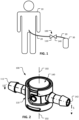
- the low-spillage quick disconnect 100 is being used along a urine drainage line 20 between a patient 10 and a fluid collection bag 30.
- the fluid collection bag 30 will need to be emptied (e.g., by a nurse, healthcare aide, or other type of patientcare attendant). While the bag 30 needs to be emptied, the patient-end of the urine drainage line 20 usually needs to stay in place relative to the patient 10.
- the low-spillage quick disconnect 100 can be particularly useful in such a situation.
- the low-spillage quick disconnect 100 can be opened (e.g., disconnected, separated, or decoupled).
- a first body portion 110 of the low-spillage quick disconnect 100 can be uncoupled from and separated from a second body portion 140 of the low-spillage quick disconnect 100.
- the low-spillage design features of the low-spillage quick disconnect 100 come into use. That is, while body portions 110 and 140 are separated, apertures of the body portions 110 and 140 that would otherwise be open are instead occluded to inhibit or prevent fluid spillage from the body portions 110 and 140.
- an example embodiment of the low-spillage quick disconnect 100 is shown in a first coupled configuration.
- this first coupled configuration an open flow path exists between a first port 112 of the first body portion 110 and a second port 142 of the second body portion 140.
- the depicted embodiment of the low-spillage quick disconnect 100 includes barbed connections for coupling with a flexible tube or hose, it should be understood that any type of fluid handling connection can be used.
- connections such as, but not limited to, tube stems, bond ports, a barbed fitting (as shown), a luer fitting, a compression fitting, a quick disconnect fitting, a threaded fitting (internal or external), a sanitary fitting, a pigtail, a T-fitting, a Y-fitting, a bag fitment, and any other suitable type of configuration can be included such that the fluid coupling device 100 is suitable for connection to a fluid system as desired.
- the low-spillage quick disconnect 100 may be supplied with removable caps (not shown), or another type of component, that is releasably coupled with the ends that define the ports 112 and/or 142.
- FIG. 5 a longitudinal cross-section of the low-spillage quick disconnect 100 taken along section line 5--5 (as shown in FIG. 2 ) is illustrated.
- the open flow path between the first port 112 of the first body portion 110 and the second port 142 of the second body portion 140 is visible. It can also be seen that the open flow path through the low-spillage quick disconnect 100 is linear and unobstructed. Hence, the pressure drop and flow resistance through the low-spillage quick disconnect 100 is quite minimal.
- FIG. 5 also reveals two other internally-located components of the low-spillage quick disconnect 100.
- the two other components are a shut-off member 130 and a core member 160.
- the structures and functions of the shut-off member 130 and the core member 160 are described further below.
- the low-spillage quick disconnect 100 can be reconfigured between the first coupled configuration as shown in FIG. 2 and a second coupled configuration as shown in FIG. 3 .
- the body portions 110 and 140 are movably coupled with each other to facilitate the reconfiguration between the first and second coupled configurations.
- a close comparison of the first and second configurations reveals that, in the depicted embodiment, the body portions 110 and 140 are pivotably or rotatably coupled with each other, and therefore rotatable relative to each other about a central axis 102.
- the axis 102 is perpendicular to the open flow path defined between the first port 112 of the first body portion 110 and the second port 142 of the second body portion 140 (while the low-spillage quick disconnect 100 is in the first coupled configuration as shown in FIGS. 2 and 5 ).
- FIG. 6 a longitudinal cross-section of the low-spillage quick disconnect 100 taken along section line 6--6 (as shown in FIG. 3 ) is illustrated.
- this view it can be seen that there is no open flow path between the first port 112 of the first body portion 110 and the second port 142 of the second body portion 140. Rather, the lumen defined by the first body portion 110 is occluded by the shut-off member 130, and the lumen defined by the second body portion 140 is occluded by the core member 160.
- a comparison between the longitudinal cross-sectional views of FIGS. 5 and 6 reveals that, while the body portions 110 and 140 have been rotated in relation to each other by a particular angular amount (e.g., about 90 degrees in the depicted embodiment), the core member 160 has rotated by less than that particular angular amount (e.g., the core member has rotated by about 45 degrees in the depicted embodiment).
- a particular angular amount e.g., about 90 degrees in the depicted embodiment
- the core member 160 has rotated by less than that particular angular amount (e.g., the core member has rotated by about 45 degrees in the depicted embodiment).
- the body portions 110 and 140 of the low-spillage quick disconnect 100 are manually separable from each other. That is, when the low-spillage quick disconnect 100 is in the second coupled configuration (e.g., as shown in FIGS. 3 and 6 ), the body portions 110 and 140 can be separated from each other by moving them apart from each other along the central axis 102.
- separated body portions 110 and 140 can be recoupled to each other in order to reconnect them in a fluid system, and to reestablish fluid flow through the low-spillage quick disconnect 100.
- the process of coupling or recoupling separated body portions 110 and 140 is simply the reverse of the decoupling process.
- shut-off member 130 is retained in a coupled arrangement with the first body portion 110
- the core member 160 is retained in a coupled arrangement with the second body portion 140. Accordingly, while the body portions 110 and 140 are separated, the lumen defined by the first body portion 110 is occluded by the shut-off member 130, and the lumen defined by the second body portion 140 is occluded by the core member 160 (as seen in FIG. 6 ).
- the occlusion provided by the shut-off member 130 and the core member 160 inhibits and substantially prevents spillage from the body portions 110 and 140 while they are separated from each other.
- first body portion 110 is shown in isolation from the other components of the low-spillage quick disconnect 100. Accordingly, greater detail of the first body portion 110 is now visible.
- the first body portion 110 defines an internal space 120 that is shaped and sized to receive the second body portion 140 ( FIGS. 15-18 ). Accordingly, the body portions 110 and 140 can be selectively mated and movably coupled with each other as described in reference to FIGS. 2 and 3 .
- An annular groove 122 is defined circumferentially along an inner wall of the first body portion 110 within the internal space 120.
- the annular groove 122 is shaped and sized to releasably engage with, and slidingly mate with, a corresponding annular protrusion located around a circumference of the second body portion (as described further below in reference to FIGS. 15-18 ). Accordingly, when the body portions 110 and 140 are pushed into engagement with each other, auditory and/or tactile feedback may be generated as a result of the engagement of the annular groove 122 and the annular protrusion. Simply stated, the two body portions 110 and 140 may snap together, for example.
- the engagement of the annular groove 122 and the annular protrusion can serve to releasably detain the body portions 110 and 140 in the second coupled arrangement ( FIG. 3 ). Accordingly, separation of the body portions 110 and 140 (as depicted in FIG. 4 ) necessitates an intentional action by a user of the low-spillage quick disconnect 100.
- the first body portion 110 also defines an L-shaped slot 124.
- the L-shaped slot 124 is sized and shaped to define a clearance pathway that slidingly receives the fluid handling connection 141 ( FIGS. 15-18 ) of the second body portion 140.
- the pathway defined by the L-shaped slot 124 facilitates both: (i) the relative movements of the body portions 110 and 140 between the uncoupled/separated arrangement as shown in FIG. 4 and the second coupled configuration as shown in FIG. 3 , and (ii) the relative movements of the body portions 110 and 140 between the first coupled arrangement as shown in FIG. 2 and the second coupled arrangement as shown in FIG. 3 .
- the L-shaped slot 124 prevents separation of the body portions 110 and 140 unless the low-spillage quick disconnect 100 is in the second coupled configuration as shown in FIG. 3 . Accordingly, the L-shaped slot 124 prevents separation of the body portions 110 and 140 unless the lumens defined within the low-spillage quick disconnect 100 are occluded. In this manner, the L-shaped slot 124 provides a fail-safe feature.
- the first body portion 110 also includes a mechanism that engages with the core member 160 ( FIGS. 19-22 ).
- the first body portion 110 includes a projection 126 (like a mechanical key member) that engages with a corresponding recess 166 defined by the core member 160 (as described further below in reference to FIG. 21 ).
- the mechanical interaction between the projection 126 and the corresponding recess defined by the core member 160 serves to limit how much the core member 160 can rotate or pivot in relation to the first body portion 110.
- the first body portion 110 (and/or one or more other components of the low-spillage quick disconnect 100) is made of a thermoplastic material.
- the first body portion 110 is made of a thermoplastic, such as, but not limited to, polycarbonate, polysulfone, polyether ether ketone, polysulphide, polyester, polyvinylidene fluoride (PVDF), polyethylene, polyphenylsulfone (PPSU; e.g., Radel ® ), polyetherimide (PEI; e.g., Ultem ® ), polypropylene, polyphenylene, polyaryletherketone, Acrylonitrile butadiene styrene (ABS), and the like, and combinations thereof.
- PVDF polyvinylidene fluoride
- PPSU polyphenylsulfone
- PEI polyetherimide
- ABS Acrylonitrile butadiene styrene
- the inner wall 121 (or portions thereof) that defines the internal space 120 is overmolded or coated with a softer material that seals against the second body portion 140 and/or the shut-off member 130 (which can each be made of harder materials).
- a softer seal material such as, but not limited to, silicone, fluoroelastomers (FKM), ethylene propylene diene monomer (EPDM), thermoplastic elastomers (TPE), buna, buna-N, thermoplastic vulcanizates (TPV), and the like.
- a softer seal material is overmolded as an annular band around the aperture 128.
- some embodiments of the first body portion 110 include an o-ring seal member positioned around the aperture 128.
- the first body portion 110 also defines a first aperture 128 which is at an opposite end of the fluid handling connection 111 that defines the first lumen extending from the first port 112.
- first aperture 128 is occluded so that fluid spillage from the first body portion 110 is inhibited and substantially prevented.
- the shut-off member 130 is movably positioned within, and remains captured within, the internal space 120 so that it can occlude the first aperture 128 while the first body portion 110 is separated from the second body portion 140 (as shown in FIG. 4 ).
- the first body portion 110 defines an annular seal seat 129 that slidably receives a correspondingly-sized and shaped seal base 132 of the shut-off member 130.
- the first body portion 110 includes one or more tabs (not shown) that loosely abut the top surface of the annular seal base 132 to mechanically detain the shut-off member 130 in the first body portion 110. Indeed, the shut-off member 130 and the first body portion 110 remain coupled together during use (both while the body portions 110 and 140 are coupled, and while the body portions 110 and 140 are separated).
- the annular seal base 132 defines an optional split 133 (e.g., the annular seal base 132 is an open C-shape) to facilitate assembly of the shut-off member 130 to the first body portion 110.
- the sidewall portion 134 is sized and shaped to releasably engage with a correspondingly-sized and shaped cutout defined by the second body portion 140 (as described further below in reference to FIGS. 15-18 ).
- the optional split 133 can still be included in a cylindrical design. In such a case, the optional split 133 would be a notch out of the end of the cylinder.
- the shut-off member 130 can be made of any of the materials described above in reference to the first body portion 110. Alternatively, or additionally, in some embodiments the shut-off member 130 (or portions thereof, e.g., by overmolding) is made of materials such as, but not limited to, silicone, FKM, buna, buna-N, EPDM, TPE, TPV, and the like.
- an example second body portion 140 is shown in isolation from the other components of the low-spillage quick disconnect 100. Accordingly, greater detail of the second body portion 140 is now visible.
- the second body portion 140 can be made of any of the materials described above in reference to the first body portion 110.
- the second body portion 140 includes a generally cylindrical body 144 that is configured to be releasably received within the internal space 120 defined by the first body portion 110 as shown in FIGS. 7 and 9 .
- the second body portion 140 also includes a fluid handling connection 141 that can extend through the L-shaped slot 124 of the first body portion 110.
- the second body portion 140 includes an annular protrusion 145 that is shaped and sized to releasably engage with, and slidingly mate with, the annular groove 122 of the first body portion 110 ( FIGS. 7-10 ).
- the second body portion 140 includes a cutout 146 that is sized and shaped to releasably engage with the sidewall portion 134 of the shut-off member 130 ( FIGS. 11-14 ).
- the engagement between the cutout 146 and the sidewall portion 134 ensures that rotations of the second body portion 140 in relation to the first body portion 110 also cause corresponding rotations of the shut-off member 130 in relation to the first body portion 110. That physical relationship between the cutout 146 and the sidewall portion 134 is visible by comparing the configurations of FIGS. 5 and 6 to each other.
- the area of the cutout 146 can be a portion of the generally cylindrical body 144 with a thinner wall than other portions of the generally cylindrical body 144.
- Such a more completely cylindrical design of the second body portion 140 may provide advantages such as increased rigidity and shape-stability. Since the area of the cutout 146 would have a thinner wall than other portions of the generally cylindrical body 144, mechanical engagement between the second body portion 140 and the sidewall portion 134 of the shut-off member 130 would still be facilitated.
- the generally cylindrical body 144 of the second body portion 140 also defines two apertures: (i) a second aperture 147 and (ii) a third aperture 148.
- the second aperture 147 and the third aperture 148 are referred to as “second” and "third” to distinguish them from the first aperture 128 of the first body portion 110, as described above.
- the second aperture 147 is at an opposite end of the fluid handling connection 141 that defines the second lumen extending from the second port 142.
- the generally cylindrical body 144 of the second body portion 140 also defines an internal space 149.
- the internal space 149 is generally cylindrical.
- the cutout 146, the second aperture 147, and the third aperture 148 are open to the internal space 149.
- the core member 160 includes a generally cylindrical body 162 that can be movably positioned within internal space 149 so that it can occlude the second aperture 147 and the third aperture 148 while the second body portion 140 is separated from the first body portion 110 (as shown in FIG. 4 ).
- the core member 160 When the core member 160 is rotated in relation to the second body portion 140 such that the third lumen 164 is not in alignment with the second and third apertures 147 and 148, then the core member 160 occludes the second and third apertures 147 and 148, and flow through the low-spillage quick disconnect 100 is prevented.
- Such an arrangement exists while the low-spillage quick disconnect 100 is in the second coupled configuration ( FIGS. 3 and 6 ), and also while the first and second body portions 110 and 140 are separated from each other ( FIG. 4 ).
- the third lumen 164 is not in alignment with the second and third apertures 147 and 148, then the third lumen 164 is itself also occluded at each end thereof by the inner wall of the second body portion 140.
- the core member 160 also defines a recess 166.
- the recess 166 has a cross-sectional shape that resembles a bow tie. Like a mechanical key within a keyway, the recess 166 physically receives the projection 126 of the first body portion 110 ( FIGS. 7-10 ), while defining additional clearance space there between. Since the recess 166 is larger than the projection 126, the mechanical interaction between the projection 126 and the recess 166 allows the core member 160 to rotate or pivot in relation to the first body portion 110, but also limits how much the core member 160 can rotate or pivot in relation to the first body portion 110.
- connections such as, but not limited to, barbed connections, bond ports, a luer fitting, a compression fitting, a quick disconnect fitting, a threaded fitting (internal or external), a sanitary fitting, a pigtail, a T-fitting, a Y-fitting, a bag fitment, and any other suitable type of configuration can be included such that the fluid coupling device 200 is suitable for connection to a fluid system as desired.
- the low-spillage quick disconnect 200 may be supplied with removable caps and/or plugs (not shown), or another type of component, that is releasably coupled with the ends that define the ports 212 and/or 242.
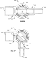
- FIG. 26 a longitudinal cross-section of the low-spillage quick disconnect 200 taken along section line 26-26 (as shown in FIG. 23 ) is illustrated.
- the open flow path between the first port 212 of the first body portion 210 and the second port 242 of the second body portion 240 is visible.
- the open flow path through the low-spillage quick disconnect 200 is linear and unobstructed. Hence, the pressure drop and flow resistance through the low-spillage quick disconnect 200 is quite minimal.
- FIGS. 26 and 27 A comparison between the longitudinal cross-sectional views of FIGS. 26 and 27 reveals that, while the body portions 210 and 240 have been rotated in relation to each other by a particular angular amount (e.g., about 90 degrees in the depicted embodiment), the core member 260 has rotated by less than that particular angular amount (e.g., the core member has rotated by about 45 degrees in the depicted embodiment). In addition, while in the depicted embodiment the body portions 210 and 240 have been rotated in relation to each other by 90 degrees and the core member 260 has rotated by about 45 degrees, the shut-off member 230 has rotated by about 30 degrees. These functional relationships between the components of the low-spillage quick disconnect 200 contribute to the low-spill characteristics of the low-spillage quick disconnect 200, and will be described further below.
- a particular angular amount e.g., about 90 degrees in the depicted embodiment
- the core member 260 has rotated by less than that particular angular amount (
- the shut-off member 230 is retained in a coupled arrangement with the first body portion 210, and the core member 260 (not visible) is retained in a coupled arrangement with the second body portion 240. Accordingly, while the body portions 210 and 240 are separated, the lumen defined by the first body portion 210 is occluded by the shut-off member 230, and the lumen defined by the second body portion 240 is occluded by the core member 260 (as seen in FIG. 27 ).
- the occlusion provided by the shut-off member 230 and the core member 260 inhibits and substantially prevents spillage from the body portions 210 and 240 while they are separated from each other.
- first body portion 210 is shown in isolation from the other components of the low-spillage quick disconnect 200. Accordingly, greater detail of the first body portion 210 is now visible.
- the first body portion 210 defines an internal space 220 that is shaped and sized to receive the second body portion 240 ( FIGS. 36-39 ). Accordingly, the body portions 210 and 240 can be selectively mated and movably coupled with each other as described in reference to FIGS. 23-27 .
- auditory and/or tactile feedback may be generated as a result of the engagement of the annular groove 222 and the one or more protrusions of the second body portion 240.
- the two body portions 210 and 240 may snap together, for example, and a "click" sound and/or tactile feedback may be generated.
- the engagement of the annular groove 222 and the one or more protrusions can serve to releasably detain the body portions 210 and 240 in the second coupled arrangement ( FIG. 24 ). Accordingly, separation of the body portions 210 and 240 (as depicted in FIG. 25 ) necessitates an intentional action by a user of the low-spillage quick disconnect 200.
- the first body portion 210 (or one or more portions thereof) is transparent or translucent so that internal components and/or fluids are visible. In some embodiments, the first body portion 210 (or one or more portions thereof) are overmolded with a second type of moldable material. In some embodiments, the low-spillage quick disconnect 200 is entirely metallic-free. That is, in some embodiments no metallic materials are included in the low-spillage quick disconnect 200. In some embodiments, one or more of the components of the low-spillage quick disconnect 200 (e.g., the first body portion 210, the second body portion 240, etc.) are made of metals such as, but not limited to, stainless steel, brass, aluminum, beryllium copper, and the like.
- first body portion 210 and the second body portion 240 and/or the shut-off member 230 can serve to maintain the sterility of a sterilized low-spillage quick disconnect 200 during storage and use. That is, such seal(s) prevents the entrance of bio-contamination between the first body portion 210 and the second body portion 240 and/or shut-off member 230 that could otherwise enter into the first and second lumens defined by the first and second body portions 210 and 240.
- the seal performs that role during storage, and also during reconfiguration of the low-spillage quick disconnect 200 between the first and second coupled configurations (as shown in FIGS. 23 and 24 ).
- the seal(s) described above is/are comprised of a soft material on the surface of the inner wall 221 which abuts against a harder material of the second body portion 240 and/or the shut-off member 230
- the locations of the soft and hard materials can be reversed. That is, in some embodiments the inner wall 221 of the first body portion 210 can be a hard material and one or more portions (or an entirety) of surface of the second body portion 240 and/or the shut-off member 230 can be overmolded with a softer material.
- the sidewall portion 234 makes up a portion of a cylinder. That is, additional material is included such that, rather than having a cantilevered sidewall portion 234, the shut-off member 230 is shaped as a hollow cylinder and sidewall portion 234 is within or part of the wall of that hollow cylinder.
- Such a cylindrical design may provide advantages such as increased rigidity and shape-stability.
- the sidewall portion 234 can be thicker than other portions of the cylinder wall.
- an example second body portion 240 is shown in isolation from the other components of the low-spillage quick disconnect 200. Accordingly, greater detail of the second body portion 240 is now visible.
- the second body portion 240 can be made of any of the materials described above in reference to the first body portion 210.
- the second body portion 240 includes a generally cylindrical body 244 that is configured to be releasably received within the internal space 220 defined by the first body portion 210 as shown in FIGS. 28 and 30 .
- the second body portion 240 also includes a fluid handling connection 241 that can extend through and travel within the L-shaped slot 224 of the first body portion 210.
- the second body portion 240 includes one or more protrusions 245 that is/are shaped and sized to releasably engage with, and slidingly mate with, the annular groove 222 of the first body portion 210 ( FIGS. 28-31 ).
- the second body portion 240 includes a cutout 246 that is sized and shaped to releasably engage with the sidewall portion 234 of the shut-off member 230 ( FIGS. 32-35 ).
- the engagement between the cutout 246 and the sidewall portion 234 ensures that rotations of the second body portion 240 in relation to the first body portion 210 also cause corresponding rotations of the shut-off member 230 in relation to the first body portion 210. That physical relationship between the cutout 246 and the sidewall portion 234 is visible by comparing the configurations of FIGS. 26 and 27 to each other.
- the cutout 246 is larger than the sidewall portion 234 of the shut-off member 230 ( FIGS. 32-35 ).
- the sidewall portion 234 of the shut-off member 230 is positioned within the cutout 246 of the second body portion 240, spatial clearance exists between the side(s) of the sidewall portion 234 and the cutout 246. Accordingly, while rotations of the second body portion 240 tend to drive rotations of the shut-off member 230 (as a result of the engagement between the cutout 246 and the sidewall portion 234), the resulting rotation of the shut-off member 230 will be less than the rotation of the second body portion 240 in some circumstances. For example, by comparing the configurations of FIGS.
- the area of the cutout 246 can be a portion of the generally cylindrical body 244 with a thinner wall than other portions of the generally cylindrical body 244.
- Such a more completely cylindrical design of the second body portion 240 may provide advantages such as increased rigidity and shape-stability. Since the area of the cutout 246 would have a thinner wall than other portions of the generally cylindrical body 244, mechanical engagement between the second body portion 240 and the sidewall portion 234 of the shut-off member 230 would still be facilitated.
- the generally cylindrical body 244 of the second body portion 240 also defines an aperture 247.
- the aperture 247 is at an opposite end of the fluid handling connection 241 that defines the second lumen extending from the second port 242.
- the second aperture 247 is occluded by the core member 260 (as shown in FIG. 27 ) so that fluid spillage from the second body portion 240 is inhibited and substantially prevented.
- the generally cylindrical body 244 of the second body portion 240 also defines an internal space 249.
- the internal space 249 is generally cylindrical.
- the cutout 246 and the aperture 247 are open to the internal space 249.
- the depicted embodiment of the second body portion 240 also includes an annular undercut area 248 that mechanically engages (e.g., using a snap-in slip fit) with one or more tabs 261 of the core member 260 (refer to FIGS. 40 and 43 ), while still allowing for relative rotation between the second body portion 240 and the core member 260. Accordingly, the core member 260 and the second body portion 240 remain rotatably coupled together during use (during both: (i) while the body portions 210 and 240 are coupled, and (ii) while the body portions 210 and 240 are separated).
- the second body portion 240 can also include a hard stop member 251 ( FIG. 36 ).
- the hard stop member 251 is positioned to abut against a stop surface 214 ( FIG. 28 ) of the first body portion 210 when the low-spillage quick disconnect 200 is configured in the second coupled configuration as shown in FIG. 24 . That is, contact between the hard stop member 251 and the stop surface 214 establishes the rotational orientation between the first body portion 210 and the second body portion 240 while the low-spillage quick disconnect 200 is configured in the second coupled configuration.
- the core member 260 includes a generally cylindrical body 262 that can be movably positioned within internal space 249 of the second body portion 240 so that it can occlude the aperture 247 while the second body portion 240 is separated from the first body portion 210 (as shown in FIG. 25 ).
- the core member 260 can be made of any of the materials described above in reference to the first body portion 210. Alternatively, or additionally, in some embodiments the core member 260 (or portions thereof, e.g., by overmolding) is made of materials such as, but not limited to, silicone, buna, buna-N, FKM, EPDM, TPE, TPV, and the like.
- the core member 260 can include one or more tabs 261.
- the one or more tabs 261 can be sized and shaped to releasably engage with, and slidingly mate with, a corresponding undercut area 248 ( FIG. 38 ) that is defined within the internal space 249 of the second body portion 240. Engagement of the tabs 261 with such a corresponding undercut area 248 can ensure that the core member 260 remains coupled within the internal space 249 of the second body portion 240 while also being rotatably movable relative to the second body portion 240.
- the core member 260 defines a lumen 264 that extends laterally, fully through the generally cylindrical body 262.
- annular protrusions extending laterally from the generally cylindrical body 262 define the ends of the lumen 264. Such annular protrusions can help to seal the fluid flow path through the low-spillage quick disconnect 200 (while open and/or while closed).
- the lumen 264 of the core member 260 can serve as a fluid flow path in conjunction with the aperture 247 of the second body portion 240 (and in conjunction with the aperture 238 of the shut-off member 230). That is, when the low-spillage quick disconnect 200 is in the first coupled configuration ( FIGS. 23 and 26 ), an open fluid flow path is defined between the first and second ports 212 and 242.
- the core member 260 also includes one or more annular seals 263 partially or fully around the circumference of the core member 260.
- one or more annular seals 263 are included on opposite sides of the openings to the lumen 264.
- the one or more annular seals 263 can be made of a suitable type of compliant plastic or rubber.
- the core member 260 also defines a recess 266.
- the recess 266 has a cross-sectional shape that resembles a bow tie. Like a mechanical key within a keyway, the recess 266 physically receives the projections 226a-b of the first body portion 210 ( FIGS. 28-31 ), while defining additional clearance space there between. Since the recess 266 is larger than the projections 226a-b, the mechanical interaction between the projections 226a-b and the recess 266 allows the core member 260 to rotate or pivot in relation to the first body portion 210, but also limits how much the core member 260 can rotate or pivot in relation to the first body portion 210.
- the core member 260 is an injection molded part.
- a core member can be made using a two-shot (overmolded) process.
- the core member 260' can be made of any of the materials described above in reference to the first body portion 210. Alternatively, or additionally, in some embodiments the core member 260' (or portions thereof, e.g., by overmolding) is made of materials such as, but not limited to, silicone, buna, buna-N, FKM, EPDM, TPE, TPV, and the like.
- That open fluid flow path extends from the first port 212 through: (i) the lumen defined by the fluid handling connection 211 of the first body portion 210, (ii) the aperture 228 of the first body portion 210, (iii) the aperture 238 of the shut-off member 230, (iv) the lumen 264' of the core member 260', (v) the aperture 247 of the second body portion 240, (vi) the lumen defined by the fluid handling connection 241 of the second body portion 240, and then to the second port 242.
- the core member 260' also includes one or more annular seals 263' partially or fully around the circumference of the core member 260'. In the depicted embodiment, two annular seals 263' are included on opposite sides of the openings to the lumen 264'. The one or more annular seals 263' can be made of a suitable type of compliant plastic or rubber.
- the core member 260' also defines a recess 266'. In the depicted embodiment, the recess 266' has a cross-sectional shape that resembles a bow tie. Like a mechanical key within a keyway, the recess 266' physically receives the projections 226a-b of the first body portion 210 ( FIGS.
- the recess 266' is larger than the projections 226a-b, the mechanical interaction between the projections 226a-b and the recess 266' allows the core member 260' to rotate or pivot in relation to the first body portion 210, but also limits how much the core member 260' can rotate or pivot in relation to the first body portion 210.
- a system 300 includes the low-spillage quick disconnect 200 (or any other embodiment of low-spillage quick disconnect described herein) and a mounting patch 310.
- the mounting patch 310 is an adhesive patch such that the mounting patch 310 can be adhered to surfaces such as, but not limited, a patient's skin or clothing.
- the second body portion 240' includes a generally cylindrical body 244' that is configured to be releasably received within the internal space 220 defined by the first body portion 210 as shown in FIGS. 28 and 30 .
- the second body portion 240' also includes a fluid handling connection 241' that can extend through and travel within the L-shaped slot 224 of the first body portion 210.
- shut-off member 230 was rotated by about 30 degrees.
- the benefit of such an arrangement is that the exposure of the shut-off member 230 to the ambient environment is lessened.
- the shut-off member 230 is completely within the confines of the first body portion 210 while the low-spillage quick disconnect 400 is configured in the second coupled configuration.
- the shut-off member 230 is essentially completely within the confines of the first body portion 210 while the low-spillage quick disconnect 400 is configured in the first coupled configuration.
- the area of the cutout 246' includes a portion of the generally cylindrical body 244' that has a thinner wall than other portions of the generally cylindrical body 244'.
- Such a more partially complete cylindrical design of the second body portion 240' may provide advantages such as increased rigidity and shape-stability. Since the area of the cutout 246' that has a thinner wall than other portions of the generally cylindrical body 244' still allows for mechanical engagement between the second body portion 240' and the sidewall portion 234 of the shut-off member 230 (as seen in FIGS. 55 and 56 ).
- an additional feature or component is included to prevent accidental or inadvertent reconfiguration of the low-spillage quick disconnect 100 away from the first coupled configuration in which an open flow path exists between the first port 112 of the first body portion 110 and the second port 142 of the second body portion 140.
- a latch mechanism is included that must be actuated to allow relative rotation of the first and second body portions 110 and 140.
- a cover component is included that retains the first and second body portions 110 and 140 in the first coupled configuration (in which the fluid handling connections 111 and 141 are linearly aligned). In some cases, such a cover component must be removed to allow relative rotation of the first and second body portions 110 and 140.
- such a cover component can be integral to the low-spillage quick disconnect 100 so that it can be pivoted, deflected, slid, or otherwise moved out of the way to allow relative rotation of the first and second body portions 110 and 140 while not totally separating the cover component from other portions of the low-spillage quick disconnect 100.
- the fluid handling connections of the body portions described herein can include a flange or physical stop member that positionally limits the installation depth of a tube that is pressed onto the fluid handling connections. Excessive tube installation could cause interference with the rotational action of the low-spillage quick disconnects and flanges or stop members can prevent such a situation.
- the assembled the low-spillage quick disconnects described herein is sterilized prior to use.
- Any suitable sterilization method can be used, such as gamma sterilization, ethylene oxide sterilization, e-beam sterilization, Noxilizer TM sterilization, Revox ® sterilization, or using an autoclave, and the like.
- the assembled the low-spillage quick disconnect may be coupled with tubing and/or other components prior to sterilization, and the assembly is sterilized in the coupled/assembled configuration.
Landscapes
- Health & Medical Sciences (AREA)
- Engineering & Computer Science (AREA)
- Heart & Thoracic Surgery (AREA)
- General Engineering & Computer Science (AREA)
- Animal Behavior & Ethology (AREA)
- Public Health (AREA)
- Veterinary Medicine (AREA)
- Life Sciences & Earth Sciences (AREA)
- Biomedical Technology (AREA)
- General Health & Medical Sciences (AREA)
- Anesthesiology (AREA)
- Hematology (AREA)
- Pulmonology (AREA)
- Mechanical Engineering (AREA)
- Epidemiology (AREA)
- Nursing (AREA)
- Orthopedic Medicine & Surgery (AREA)
- Vascular Medicine (AREA)
- Quick-Acting Or Multi-Walled Pipe Joints (AREA)
Description
- This application claims priority to
U.S. Application Serial No. 62/659,473, filed on April 18, 2018 U.S. Application Serial No. 62/564,726, filed September 28, 2017 - This document relates to fluid handling devices for use in fluid systems. For example, some embodiments described in this document relate to a quick disconnect type of fluid coupling device that inhibits fluid spillage during and after disconnection.
- Fluid systems commonly include components such as tubing, couplings, valves, pumps, reservoirs, filters, and the like. Such components can be connected together in a network to define a fluid flow path.
- Fluid systems are often used in a medical context. Some examples of fluid systems used in the medical context include urinary drainage systems, wound drainage systems, infusion systems, respiratory systems, anesthesia systems, blood transfusion circuits, kidney dialysis systems, extracorporeal membrane oxygenation systems, extracorporeal circuits for heart/lung bypass, and the like. Some such medical fluid systems include the use of quick disconnect fluid coupling devices.
-
US 2016/022538 A1 describes a method for forming an aseptic connection. The method includes inserting an end of a sealed fill connector into a receptacle of an aseptic connector assembly; moving a pivot portion of the aseptic connector assembly relative to a body portion of the aseptic connector assembly so as to sever a portion of the fill connector, the pivot portion being at least partially disposed within the body portion; and advancing a conduit portion of the aseptic connector assembly into the fill connector so as to form an aseptic connection therebetween, the conduit portion being at least partially disposed within the pivot portion or the body portion of the aseptic connector assembly after advancing. - The invention is defined by the claims.
- This document describes fluid handling devices for use in fluid systems. For example, some embodiments described in this document relate to a quick disconnect type of fluid coupling device that prevents, inhibits, or minimizes fluid spillage during and after disconnection. For example, particular embodiments of these fluid coupling devices can be configured to improve medical fluid handling equipment because the fluid coupling devices can be connected and disconnected (e.g., multiple times) while minimizing fluid spillage. In the context of this disclosure, the term "fluid" includes both gases and liquids.
- According claim 1, a fluid handling device includes a first body portion defining a first lumen extending between a first port and a first aperture, and a second body portion defining a second lumen extending between a second port and a second aperture. The first and second body portions are: (i) coupleable with each other and (ii) separable from each other. While the first and second body portions are separated from each other, the first and second apertures are each occluded. While the first and second body portions are coupled with each other, the fluid handling device is configurable in: (a) a first coupled configuration in which an open flow path is defined between the first and second ports and (b) a second coupled configuration in which the first and second apertures are each occluded.
- The first body portion is pivotable in relation to the second portion to reconfigure the fluid handling device between the first and second coupled configurations. The fluid handling device may also include a core member pivotably coupled with the second body portion. Pivoting the first and second body portions between the first and second coupled configurations may cause the core member to pivot in relation to each of the first and second body portions. An engagement mechanism between the first body portion and the core member may limit how much the core member can pivot in relation to the first body portion. The fluid handling device may also include a core member movably coupled with the second body portion. The core member may define a central lumen. The open flow path may comprise the central lumen. The open flow path may be linear and unobstructed. While the first and second body portions are separated from each other, each end of the central lumen may be occluded by the second body portion. The fluid handling device may also include a seal between the first body portion and the second body portion. The seal may include a first material in contact with a second material that is softer than the first material. The seal may prevent entrance of bio-contamination into the first and second lumens. The seal may prevent entrance of bio-contamination into the first and second lumens during reconfiguration of the fluid handling device between the first and second coupled configurations.
- Particular embodiments of the subject matter described in this document can be implemented to realize one or more of the following advantages. First, in some embodiments the fluid coupling devices described herein are configured to allow fluid flow therethrough, and subsequently to allow the coupling halves to be uncoupled and separated while minimizing spillage of the fluid. Such a low-spillage quick disconnect fluid coupling device can be used while advantageously mitigating contamination caused by spillage of fluids that can be messy or even hazardous (e.g., biohazardous, corrosive, etc.). Associated safety risks and clean-up costs can thereby be reduced or eliminated.
- Second, in some embodiments the fluid coupling devices provided herein are configured to convey fluid flow with a minimized amount of pressure drop and flow restriction. For example, some embodiments of the fluid coupling device can be configured for connection to 6.35 mm (1/4 inch) inside diameter tubing while also having a pressure drop that is similar to the pressure drop of an equivalent length of 6.35 mm (1/4 inch) inside diameter tubing.
- Third, in some embodiments, the fluid coupling systems may advantageously provide a user with audible and/or tactile feedback in response to the motions performed for physically connecting and disconnecting the two portions of the fluid coupling devices in relation to each other. Such audible and/or tactile feedback can provide the user with an efficient and conclusive indication or confirmation of the proper function and desired configuration of the fluid coupling devices.
- Fourth, some embodiments are designed with fail-safe provisions. For example, the coupling halves of some embodiments are physically prevented from being separated unless the anti-spillage members are in place and active for the prevention of spillage.
- Fifth, some embodiments of the fluid coupling devices provided herein are advantageously designed with a robust locking system. That is, when the two halves of the coupling system are operably connected with each other, they are also mechanically locked in place. In some embodiments, to release the lock, special user actions are required (e.g., a latch on the coupling must be depressed). Such a design may reduce the likelihood of unintentional disconnections.
- Sixth, some embodiments have a user-friendly design that is intuitive to properly operate. Accordingly, minimal operator training is required, and user mistakes are minimized.
- Seventh, the low-spillage quick disconnect devices described herein are designed to be manufacture-able at a low cost. For example, some embodiments include only four components. The components can be molded plastic items in some cases. Moreover, in some embodiments the components can be simply snapped together (manually or automatically) for a low-cost assembly process.
- Unless otherwise defined, all technical and scientific terms used herein have the same meaning as commonly understood by one of ordinary skill in the art to which this disclosure pertains. In addition, the materials, methods, and examples of the embodiments described herein are illustrative only and not intended to be limiting.
- The details of one or more embodiments of the invention are set forth in the accompanying drawings and the description herein. Other features, objects, and advantages of the invention will be apparent from the description and drawings, and from the claims.
-
-
FIG. 1 is a schematic diagram of a human being that is connected to a urinary drainage system including an in-line low-spillage quick disconnect fluid coupling in accordance with some embodiments described herein. -
FIG. 2 is a perspective view of an example low-spillage quick disconnect fluid coupling in accordance with some embodiments. The low-spillage quick disconnect fluid coupling, as shown, is arranged in a coupled configuration that defines an open flow path through the low-spillage quick disconnect fluid coupling. -
FIG. 3 is a perspective view of the low-spillage quick disconnect fluid coupling ofFIG. 2 . The low-spillage quick disconnect fluid coupling, as shown, is arranged in a coupled configuration in which no open flow path exists through the low-spillage quick disconnect fluid coupling. -
FIG. 4 is a perspective view of the low-spillage quick disconnect fluid coupling ofFIG. 2 . The low-spillage quick disconnect fluid coupling, as shown, is arranged in an uncoupled configuration. -
FIG. 5 is a cross-sectional view of the low-spillage quick disconnect fluid coupling ofFIG. 2 in the configuration ofFIG. 2 . -
FIG. 6 is a cross-sectional view of the low-spillage quick disconnect fluid coupling ofFIG. 2 in the configuration ofFIG. 3 . -
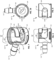
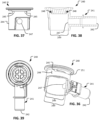
FIG. 7 is a perspective view of a first body portion of the low-spillage quick disconnect fluid coupling ofFIG. 2 . -
FIG. 8 is an end view of the first body portion ofFIG. 7 . -
FIG. 9 is a side view of the first body portion ofFIG. 7 . -
FIG. 10 is a top view of the first body portion ofFIG. 7 . -
FIG. 11 is a perspective view of a shut-off member of the low-spillage quick disconnect fluid coupling ofFIG. 2 . -
FIG. 12 is an end view of the shut-off member ofFIG. 11 . -
FIG. 13 is a side view of the shut-off member ofFIG. 11 . -
FIG. 14 is a top view of the shut-off member ofFIG. 11 . -
FIG. 15 is a perspective view of a second body portion of the low-spillage quick disconnect fluid coupling ofFIG. 2 . -
FIG. 16 is an end view of the second body portion ofFIG. 15 . -
FIG. 17 is a side view of the second body portion ofFIG. 15 . -
FIG. 18 is a top view of the second body portion ofFIG. 15 . -
FIG. 19 is a perspective view of a core member of the low-spillage quick disconnect fluid coupling ofFIG. 2 . -
FIG. 20 is a side view of the core member ofFIG. 19 . -
FIG. 21 is a bottom view of the core member ofFIG. 19 . -
FIG. 22 is another side view of the core member ofFIG. 19 . -
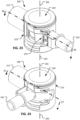
FIG. 23 is a perspective view of another example low-spillage quick disconnect fluid coupling in accordance with some embodiments. The low-spillage quick disconnect fluid coupling, as shown, is arranged in a coupled configuration that defines an open flow path through the low-spillage quick disconnect fluid coupling. -
FIG. 24 is a perspective view of the low-spillage quick disconnect fluid coupling ofFIG. 23 . The low-spillage quick disconnect fluid coupling, as shown, is arranged in a coupled configuration in which no open flow path exists through the low-spillage quick disconnect fluid coupling. -
FIG. 25 is a perspective view of the low-spillage quick disconnect fluid coupling ofFIG. 23 . The low-spillage quick disconnect fluid coupling, as shown, is arranged in an uncoupled configuration. -
FIG. 26 is a cross-sectional view of the low-spillage quick disconnect fluid coupling ofFIG. 23 in the configuration ofFIG. 23 . -
FIG. 27 is a cross-sectional view of the low-spillage quick disconnect fluid coupling ofFIG. 23 in the configuration ofFIG. 24 . -
FIG. 28 is a perspective view of a first body portion of the low-spillage quick disconnect fluid coupling ofFIG. 23 . -
FIG. 29 is an end view of the first body portion ofFIG. 28 . -
FIG. 30 is a side view of the first body portion ofFIG. 28 . -
FIG. 31 is a top view of the first body portion ofFIG. 28 . -
FIG. 32 is a perspective view of a shut-off member of the low-spillage quick disconnect fluid coupling ofFIG. 23 . -
FIG. 33 is an end view of the shut-off member ofFIG. 32 . -
FIG. 34 is a side view of the shut-off member ofFIG. 32 . -
FIG. 35 is a top view of the shut-off member ofFIG. 32 . -
FIG. 36 is a perspective view of a second body portion of the low-spillage quick disconnect fluid coupling ofFIG. 23 . -
FIG. 37 is an end view of the second body portion ofFIG. 36 . -
FIG. 38 is a cross-sectional side view of the second body portion ofFIG. 36 . -
FIG. 39 is a bottom view of the second body portion ofFIG. 36 . -
FIG. 40 is a perspective view of an example core member of the low-spillage quick disconnect fluid coupling ofFIG. 23 . -
FIG. 41 is a side view of the core member ofFIG. 40 . -
FIG. 42 is a bottom view of the core member ofFIG. 40 . -
FIG. 43 is a cross-sectional view of the core member ofFIG. 40 . -
FIG. 44 is a perspective view of another example core member of the low-spillage quick disconnect fluid coupling ofFIG. 23 . -
FIG. 45 is a side view of the core member ofFIG. 44 . -
FIG. 46 is a bottom view of the core member ofFIG. 44 . -
FIG. 47 is a cross-sectional view of the core member ofFIG. 44 . -
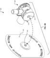
FIG. 48 is an exploded perspective view of a system for using the low-spillage quick disconnect fluid couplings described herein. -
FIG. 49 is a perspective view of another example low-spillage quick disconnect fluid coupling in accordance with some embodiments. The low-spillage quick disconnect fluid coupling, as shown, is arranged in a coupled configuration that closes a flow path through the low-spillage quick disconnect fluid coupling. -
FIG. 50 is a perspective view of the low-spillage quick disconnect fluid coupling ofFIG. 49 . The low-spillage quick disconnect fluid coupling, as shown, is arranged in an uncoupled configuration. -
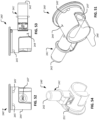
FIG. 51 is a perspective view of a second body portion of the low-spillage quick disconnect fluid coupling ofFIG. 49 . -
FIG. 52 is an end view of the second body portion ofFIG. 51 . -
FIG. 53 is a side view of the second body portion ofFIG. 51 . -
FIG. 54 is another perspective view of the second body portion ofFIG. 51 . -
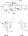
FIG. 55 is a cross-sectional view of the low-spillage quick disconnect fluid coupling ofFIG. 49 . The coupling is shown in a first coupled configuration that defines an open flow path therethrough. -
FIG. 56 is a cross-sectional view of the low-spillage quick disconnect fluid coupling ofFIG. 49 . The coupling is shown in a second coupled configuration that has a closed flow path through the low-spillage quick disconnect fluid coupling. -
FIG. 57 is another cross-sectional view of the low-spillage quick disconnect fluid coupling ofFIG. 49 . The coupling is shown in a second coupled configuration that has a hard stop member abutting a hard stop surface. - Like reference numbers represent corresponding parts throughout.
- The low-spillage quick disconnects described herein can be used in a variety of different implementations. For example, referring to
FIG. 1 , in some cases a low-spillagequick disconnect 100 as described herein can be used in a medical setting. In the depicted example, the low-spillagequick disconnect 100 is being used along aurine drainage line 20 between a patient 10 and afluid collection bag 30. - Eventually, the
fluid collection bag 30 will need to be emptied (e.g., by a nurse, healthcare aide, or other type of patientcare attendant). While thebag 30 needs to be emptied, the patient-end of theurine drainage line 20 usually needs to stay in place relative to thepatient 10. The low-spillagequick disconnect 100 can be particularly useful in such a situation. - To disconnect the
fluid collection bag 30 from being attached to thepatient 10 by theurine drainage line 20, the low-spillagequick disconnect 100 can be opened (e.g., disconnected, separated, or decoupled). In particular, afirst body portion 110 of the low-spillagequick disconnect 100 can be uncoupled from and separated from asecond body portion 140 of the low-spillagequick disconnect 100. When thebody portions quick disconnect 100 come into use. That is, whilebody portions body portions body portions - Referring to
FIG. 2 , an example embodiment of the low-spillagequick disconnect 100 is shown in a first coupled configuration. In this first coupled configuration, an open flow path exists between afirst port 112 of thefirst body portion 110 and asecond port 142 of thesecond body portion 140. While the depicted embodiment of the low-spillagequick disconnect 100 includes barbed connections for coupling with a flexible tube or hose, it should be understood that any type of fluid handling connection can be used. For example, connections such as, but not limited to, tube stems, bond ports, a barbed fitting (as shown), a luer fitting, a compression fitting, a quick disconnect fitting, a threaded fitting (internal or external), a sanitary fitting, a pigtail, a T-fitting, a Y-fitting, a bag fitment, and any other suitable type of configuration can be included such that thefluid coupling device 100 is suitable for connection to a fluid system as desired. In some embodiments, the low-spillagequick disconnect 100 may be supplied with removable caps (not shown), or another type of component, that is releasably coupled with the ends that define theports 112 and/or 142. - Referring to
FIG. 5 , a longitudinal cross-section of the low-spillagequick disconnect 100 taken along section line 5--5 (as shown inFIG. 2 ) is illustrated. In this view, the open flow path between thefirst port 112 of thefirst body portion 110 and thesecond port 142 of thesecond body portion 140 is visible. It can also be seen that the open flow path through the low-spillagequick disconnect 100 is linear and unobstructed. Hence, the pressure drop and flow resistance through the low-spillagequick disconnect 100 is quite minimal. - The cross-sectional view of
FIG. 5 also reveals two other internally-located components of the low-spillagequick disconnect 100. The two other components are a shut-offmember 130 and acore member 160. The structures and functions of the shut-offmember 130 and thecore member 160 are described further below. - Referring to
FIG. 3 , the low-spillagequick disconnect 100 can be reconfigured between the first coupled configuration as shown inFIG. 2 and a second coupled configuration as shown inFIG. 3 . Thebody portions body portions central axis 102. Theaxis 102 is perpendicular to the open flow path defined between thefirst port 112 of thefirst body portion 110 and thesecond port 142 of the second body portion 140 (while the low-spillagequick disconnect 100 is in the first coupled configuration as shown inFIGS. 2 and5 ). - In the depicted second coupled configuration, there is not an open flow path defined between the
first port 112 and thesecond port 142. Rather, the flow or the potential for flow through the low-spillagequick disconnect 100 is, occluded, stopped or blocked when the low-spillagequick disconnect 100 is configured in the second coupled configuration. - Referring to
FIG. 6 , a longitudinal cross-section of the low-spillagequick disconnect 100 taken alongsection line 6--6 (as shown inFIG. 3 ) is illustrated. In this view, it can be seen that there is no open flow path between thefirst port 112 of thefirst body portion 110 and thesecond port 142 of thesecond body portion 140. Rather, the lumen defined by thefirst body portion 110 is occluded by the shut-offmember 130, and the lumen defined by thesecond body portion 140 is occluded by thecore member 160. - A comparison between the longitudinal cross-sectional views of
FIGS. 5 and 6 reveals that, while thebody portions core member 160 has rotated by less than that particular angular amount (e.g., the core member has rotated by about 45 degrees in the depicted embodiment). These functional relationships between the components of the low-spillagequick disconnect 100 contribute to the low-spill characteristics of the low-spillagequick disconnect 100, and will be described further below. - Referring to
FIG. 4 , thebody portions quick disconnect 100 are manually separable from each other. That is, when the low-spillagequick disconnect 100 is in the second coupled configuration (e.g., as shown inFIGS. 3 and6 ), thebody portions central axis 102. - One of ordinary skill in the art will readily envision that
separated body portions quick disconnect 100. Of course, the process of coupling or recoupling separatedbody portions - While the
body portions body portions body portions ports body portions body portions - While the
body portions member 130 is retained in a coupled arrangement with thefirst body portion 110, and thecore member 160 is retained in a coupled arrangement with thesecond body portion 140. Accordingly, while thebody portions first body portion 110 is occluded by the shut-offmember 130, and the lumen defined by thesecond body portion 140 is occluded by the core member 160 (as seen inFIG. 6 ). The occlusion provided by the shut-offmember 130 and thecore member 160 inhibits and substantially prevents spillage from thebody portions - Referring to
FIGS. 7-10 , here an examplefirst body portion 110 is shown in isolation from the other components of the low-spillagequick disconnect 100. Accordingly, greater detail of thefirst body portion 110 is now visible. - The
first body portion 110 defines aninternal space 120 that is shaped and sized to receive the second body portion 140 (FIGS. 15-18 ). Accordingly, thebody portions FIGS. 2 and3 . - An
annular groove 122 is defined circumferentially along an inner wall of thefirst body portion 110 within theinternal space 120. Theannular groove 122 is shaped and sized to releasably engage with, and slidingly mate with, a corresponding annular protrusion located around a circumference of the second body portion (as described further below in reference toFIGS. 15-18 ). Accordingly, when thebody portions annular groove 122 and the annular protrusion. Simply stated, the twobody portions annular groove 122 and the annular protrusion can serve to releasably detain thebody portions FIG. 3 ). Accordingly, separation of thebody portions 110 and 140 (as depicted inFIG. 4 ) necessitates an intentional action by a user of the low-spillagequick disconnect 100. - The
first body portion 110 also defines an L-shapedslot 124. The L-shapedslot 124 is sized and shaped to define a clearance pathway that slidingly receives the fluid handling connection 141 (FIGS. 15-18 ) of thesecond body portion 140. The pathway defined by the L-shapedslot 124 facilitates both: (i) the relative movements of thebody portions FIG. 4 and the second coupled configuration as shown inFIG. 3 , and (ii) the relative movements of thebody portions FIG. 2 and the second coupled arrangement as shown inFIG. 3 . Additionally, the L-shapedslot 124 prevents separation of thebody portions quick disconnect 100 is in the second coupled configuration as shown inFIG. 3 . Accordingly, the L-shapedslot 124 prevents separation of thebody portions quick disconnect 100 are occluded. In this manner, the L-shapedslot 124 provides a fail-safe feature. - In the depicted embodiment, the terminal end (closed end or dead end) of the L-shaped
slot 124 is shaped to create adetent position 125 where the fluid handling connection 141 (FIGS. 15-18 ) of thesecond body portion 140 will snap into place. While thefluid handling connection 141 of thesecond body portion 140 is in thatdetent position 125, thebody portions FIGS. 2 and5 ) such that the open flow path exists between thefirst port 112 of thefirst body portion 110 and thesecond port 142 of thesecond body portion 140. Accordingly, thedetent position 125 provides auditory and/or tactile feedback that the low-spillagequick disconnect 100 is arranged in the first configuration (which operatively allows for fluids to flow therethrough). - The
first body portion 110 also includes a mechanism that engages with the core member 160 (FIGS. 19-22 ). For example, in the depicted embodiment thefirst body portion 110 includes a projection 126 (like a mechanical key member) that engages with acorresponding recess 166 defined by the core member 160 (as described further below in reference toFIG. 21 ). The mechanical interaction between theprojection 126 and the corresponding recess defined by thecore member 160 serves to limit how much thecore member 160 can rotate or pivot in relation to thefirst body portion 110. - In some embodiments, the first body portion 110 (and/or one or more other components of the low-spillage quick disconnect 100) is made of a thermoplastic material. In particular embodiments, the
first body portion 110 is made of a thermoplastic, such as, but not limited to, polycarbonate, polysulfone, polyether ether ketone, polysulphide, polyester, polyvinylidene fluoride (PVDF), polyethylene, polyphenylsulfone (PPSU; e.g., Radel®), polyetherimide (PEI; e.g., Ultem®), polypropylene, polyphenylene, polyaryletherketone, Acrylonitrile butadiene styrene (ABS), and the like, and combinations thereof. In some embodiments, the first body portion 110 (or one or more portions thereof) is transparent or translucent so that internal components and/or fluids are visible. In some embodiments, the first body portion 110 (or one or more portions thereof) are overmolded with a second type of moldable material. In some embodiments, the low-spillagequick disconnect 100 is entirely metallic-free. That is, in some embodiments no metallic materials are included in the low-spillagequick disconnect 100. In some embodiments, one or more of the components of the low-spillage quick disconnect 100 (e.g., thefirst body portion 110, thesecond body portion 140, etc.) are made of metals such as, but not limited to, stainless steel, brass, aluminum, beryllium copper, and the like. - In some embodiments, the inner wall 121 (or portions thereof) that defines the
internal space 120 is overmolded or coated with a softer material that seals against thesecond body portion 140 and/or the shut-off member 130 (which can each be made of harder materials). For example, one or more portions of the inner wall 121 (or the majority thereof, or the entirety thereof) can be overmolded with a softer seal material such as, but not limited to, silicone, fluoroelastomers (FKM), ethylene propylene diene monomer (EPDM), thermoplastic elastomers (TPE), buna, buna-N, thermoplastic vulcanizates (TPV), and the like. In some such embodiments, such a softer seal material is overmolded as an annular band around theaperture 128. Alternatively, some embodiments of thefirst body portion 110 include an o-ring seal member positioned around theaperture 128. - It should be understood that the inclusion of features to create one or more such seals between the
first body portion 110 and thesecond body portion 140 and/or the shut-offmember 130 can serve to maintain the sterility of a sterilized low-spillagequick disconnect 100 during storage and use. That is, such seal(s) prevents the entrance of bio-contamination between thefirst body portion 110 and thesecond body portion 140 and/or shut-offmember 130 that could otherwise enter into the first and second lumens defined by the first andsecond body portions quick disconnect 100 between the first and second coupled configurations (as shown inFIGS. 2 and3 ). - While the seal(s) described above is comprised of a soft material on the surface of the
inner wall 121 which abuts against a harder material of thesecond body portion 140 and/or the shut-offmember 130, in some embodiments the locations of the soft and hard materials can be reversed. That is, in some embodiments theinner wall 121 of thefirst body portion 110 can be a hard material and one or more portions (or an entirety) of surface of thesecond body portion 140 and/or the shut-offmember 130 can be overmolded with a softer material. - The
first body portion 110 also defines afirst aperture 128 which is at an opposite end of thefluid handling connection 111 that defines the first lumen extending from thefirst port 112. When thefirst body portion 110 is separated from the second body portion 140 (as shown inFIG. 4 ), thefirst aperture 128 is occluded so that fluid spillage from thefirst body portion 110 is inhibited and substantially prevented. - Referring also to
FIGS. 11-14 , the shut-offmember 130 is movably positioned within, and remains captured within, theinternal space 120 so that it can occlude thefirst aperture 128 while thefirst body portion 110 is separated from the second body portion 140 (as shown inFIG. 4 ). Thefirst body portion 110 defines anannular seal seat 129 that slidably receives a correspondingly-sized and shapedseal base 132 of the shut-offmember 130. - In some embodiments, the
first body portion 110 includes one or more tabs (not shown) that loosely abut the top surface of theannular seal base 132 to mechanically detain the shut-offmember 130 in thefirst body portion 110. Indeed, the shut-offmember 130 and thefirst body portion 110 remain coupled together during use (both while thebody portions body portions annular seal base 132 defines an optional split 133 (e.g., theannular seal base 132 is an open C-shape) to facilitate assembly of the shut-offmember 130 to thefirst body portion 110. - Extending from the
annular seal base 132 is asidewall portion 134. Thesidewall portion 134 is sized and shaped to releasably engage with a correspondingly-sized and shaped cutout defined by the second body portion 140 (as described further below in reference toFIGS. 15-18 ). - The
sidewall portion 134 includes a sealingprojection 136. The sealingprojection 136 is sized and shaped to releasably engage with thefirst aperture 128 like a plug or a stopper. When the sealingprojection 136 is engaged with thefirst aperture 128, a substantially fluid-tight seal is established (assuming an operating pressure that is consistent with the specifications of the particular low-spillagequick disconnect 100 being used). - While the depicted embodiment of the shut-off
member 130 includes thesidewall portion 134 that is cantilevered from theannular seal base 132, alternative designs are also envisioned. For example, in some embodiments thesidewall portion 134 makes up a portion of a cylinder. That is, additional material is included such that, rather than having a cantileveredsidewall portion 134, the shut-offmember 130 is shaped as a hollow cylinder andsidewall portion 134 is within or part of the wall of that hollow cylinder. Such a cylindrical design may provide advantages such as increased rigidity and shape-stability. In some such embodiments, thesidewall portion 134 can be thicker than other portions of the cylinder wall. That way thesidewall portion 134 can still mechanically engage with the second body portion 140 (as described further below). Theoptional split 133 can still be included in a cylindrical design. In such a case, theoptional split 133 would be a notch out of the end of the cylinder. - The shut-off
member 130 can be made of any of the materials described above in reference to thefirst body portion 110. Alternatively, or additionally, in some embodiments the shut-off member 130 (or portions thereof, e.g., by overmolding) is made of materials such as, but not limited to, silicone, FKM, buna, buna-N, EPDM, TPE, TPV, and the like. - Referring to
FIGS. 15-18 , here an examplesecond body portion 140 is shown in isolation from the other components of the low-spillagequick disconnect 100. Accordingly, greater detail of thesecond body portion 140 is now visible. Thesecond body portion 140 can be made of any of the materials described above in reference to thefirst body portion 110. - The
second body portion 140 includes a generallycylindrical body 144 that is configured to be releasably received within theinternal space 120 defined by thefirst body portion 110 as shown inFIGS. 7 and 9 . Thesecond body portion 140 also includes afluid handling connection 141 that can extend through the L-shapedslot 124 of thefirst body portion 110. - Reference will now be made to the physical features of the
second body portion 140 that were mentioned above as being releasably engageable with corresponding-sized and shaped features of thefirst body portion 110 or the shut-offmember 130. For example, thesecond body portion 140 includes anannular protrusion 145 that is shaped and sized to releasably engage with, and slidingly mate with, theannular groove 122 of the first body portion 110 (FIGS. 7-10 ). Additionally, thesecond body portion 140 includes acutout 146 that is sized and shaped to releasably engage with thesidewall portion 134 of the shut-off member 130 (FIGS. 11-14 ). The engagement between thecutout 146 and thesidewall portion 134 ensures that rotations of thesecond body portion 140 in relation to thefirst body portion 110 also cause corresponding rotations of the shut-offmember 130 in relation to thefirst body portion 110. That physical relationship between thecutout 146 and thesidewall portion 134 is visible by comparing the configurations ofFIGS. 5 and 6 to each other. - While the depicted embodiment of the
second body portion 140 includes thecutout 146, alternative designs are also envisioned. For example, in some embodiments the area of thecutout 146 can be a portion of the generallycylindrical body 144 with a thinner wall than other portions of the generallycylindrical body 144. Such a more completely cylindrical design of thesecond body portion 140 may provide advantages such as increased rigidity and shape-stability. Since the area of thecutout 146 would have a thinner wall than other portions of the generallycylindrical body 144, mechanical engagement between thesecond body portion 140 and thesidewall portion 134 of the shut-offmember 130 would still be facilitated. - The generally
cylindrical body 144 of thesecond body portion 140 also defines two apertures: (i) asecond aperture 147 and (ii) athird aperture 148. Here thesecond aperture 147 and thethird aperture 148 are referred to as "second" and "third" to distinguish them from thefirst aperture 128 of thefirst body portion 110, as described above. Thesecond aperture 147 is at an opposite end of thefluid handling connection 141 that defines the second lumen extending from thesecond port 142. When thesecond body portion 140 is separated from the first body portion 110 (as shown inFIG. 4 ), thesecond aperture 147 is occluded so that fluid spillage from thesecond body portion 140 is inhibited and substantially prevented. - The generally
cylindrical body 144 of thesecond body portion 140 also defines aninternal space 149. Theinternal space 149 is generally cylindrical. Thecutout 146, thesecond aperture 147, and thethird aperture 148 are open to theinternal space 149. - Referring also to
FIGS. 19-22 , thecore member 160 includes a generallycylindrical body 162 that can be movably positioned withininternal space 149 so that it can occlude thesecond aperture 147 and thethird aperture 148 while thesecond body portion 140 is separated from the first body portion 110 (as shown inFIG. 4 ). - The
core member 160 can be made of any of the materials described above in reference to thefirst body portion 110. Alternatively, or additionally, in some embodiments the core member 160 (or portions thereof, e.g., by overmolding) is made of materials such as, but not limited to, silicone, buna, buna-N, FKM, EPDM, TPE, TPV, and the like. - In some embodiments, the
core member 160 can include anannular protrusion 163. Theannular protrusion 163 can be sized and shaped to releasably engage with, and slidingly mate with, a corresponding annular groove (not visible) that is defined circumferentially around an inner wall of theinternal space 149 of thesecond body portion 140. Engagement of theannular protrusion 163 within such an annular groove can ensure that thecore member 160 remains coupled within theinternal space 149 of thesecond body portion 140 while also being rotatably movable relative to thesecond body portion 140. - The
core member 160 defines athird lumen 164 that extends laterally fully through the generallycylindrical body 162. Depending on the relative rotational position of thecore member 160 in relation to thesecond body portion 160, thethird lumen 164 of thecore member 160 can serve as a fluid flow path between the second andthird apertures third lumen 164 is in alignment with the second andthird apertures third lumen 164 provides a fluid flow path between the second andthird apertures 147 and 148 (and also between the first andsecond ports quick disconnect 100 is in the first coupled configuration (FIGS. 2 and5 ). - When the
core member 160 is rotated in relation to thesecond body portion 140 such that thethird lumen 164 is not in alignment with the second andthird apertures core member 160 occludes the second andthird apertures quick disconnect 100 is prevented. Such an arrangement exists while the low-spillagequick disconnect 100 is in the second coupled configuration (FIGS. 3 and6 ), and also while the first andsecond body portions FIG. 4 ). Moreover, while thethird lumen 164 is not in alignment with the second andthird apertures third lumen 164 is itself also occluded at each end thereof by the inner wall of thesecond body portion 140. - The
core member 160 also defines arecess 166. In the depicted embodiment, therecess 166 has a cross-sectional shape that resembles a bow tie. Like a mechanical key within a keyway, therecess 166 physically receives theprojection 126 of the first body portion 110 (FIGS. 7-10 ), while defining additional clearance space there between. Since therecess 166 is larger than theprojection 126, the mechanical interaction between theprojection 126 and therecess 166 allows thecore member 160 to rotate or pivot in relation to thefirst body portion 110, but also limits how much thecore member 160 can rotate or pivot in relation to thefirst body portion 110. - The
recess 166 can be designed to allow any desired amount of relative rotation between thecore member 160 and thefirst body portion 110. In the depicted embodiment, about 45 degrees of relative rotation is allowed by the mechanical interaction of therecess 166 and theprojection 126. In some embodiments, an allowed relative rotation between thecore member 160 and thefirst body portion 110 is within a range of about 40 degrees to about 50 degrees, or about 35 degrees to about 55 degrees, or about 30 degrees to about 60 degrees. - Referring to
FIG. 23 , another example embodiment of a low-spillagequick disconnect 200 is shown in a first coupled configuration. In this first coupled configuration, an open flow path exists between afirst port 212 of thefirst body portion 210 and asecond port 242 of thesecond body portion 240. While the depicted embodiment of the low-spillagequick disconnect 200 includes sleeve, socket, or nipple connections for coupling with a flexible tube or hose, it should be understood that any type of fluid handling connection can be used. For example, connections such as, but not limited to, barbed connections, bond ports, a luer fitting, a compression fitting, a quick disconnect fitting, a threaded fitting (internal or external), a sanitary fitting, a pigtail, a T-fitting, a Y-fitting, a bag fitment, and any other suitable type of configuration can be included such that thefluid coupling device 200 is suitable for connection to a fluid system as desired. In some embodiments, the low-spillagequick disconnect 200 may be supplied with removable caps and/or plugs (not shown), or another type of component, that is releasably coupled with the ends that define theports 212 and/or 242. - Referring to
FIG. 26 , a longitudinal cross-section of the low-spillagequick disconnect 200 taken along section line 26-26 (as shown inFIG. 23 ) is illustrated. In this view, the open flow path between thefirst port 212 of thefirst body portion 210 and thesecond port 242 of thesecond body portion 240 is visible. It can also be seen that the open flow path through the low-spillagequick disconnect 200 is linear and unobstructed. Hence, the pressure drop and flow resistance through the low-spillagequick disconnect 200 is quite minimal. - The cross-sectional view of
FIG. 26 also reveals two other internally-located components of the low-spillagequick disconnect 200. The two other components are a shut-offmember 230 and acore member 260. The structures and functions of the shut-offmember 230 and thecore member 260 are described further below. - Referring to
FIG. 24 , the low-spillagequick disconnect 200 can be reconfigured between the first coupled configuration as shown inFIG. 23 and a second coupled configuration as shown inFIG. 24 . Thebody portions body portions central axis 202. Theaxis 202 is perpendicular to the open flow path defined between thefirst port 212 of thefirst body portion 210 and thesecond port 242 of the second body portion 240 (while the low-spillagequick disconnect 200 is in the first coupled configuration as shown inFIGS. 23 and26 ). - The depicted embodiment of the low-spillage
quick disconnect 200 includes anoptional latch mechanism 270. When the low-spillagequick disconnect 200 is in the first coupled configuration (as shown inFIG. 23 ), thelatch mechanism 270 detains thebody portions body portions quick disconnect 200 to the second coupled configuration as shown inFIG. 24 ) unless thelatch mechanism 270 is affirmatively acted upon to unlatch or deactivate thelatch mechanism 270. Accordingly, thelatch mechanism 270 can safeguard against an accidental or unintentional closing of the open flow path defined between thefirst port 212 and thesecond port 242 that exists while the low-spillagequick disconnect 200 is in the first coupled configuration as shown inFIG. 23 . When thelatch mechanism 270 is affirmatively acted upon to deactivate it, then thebody portions quick disconnect 200 from the first coupled configuration as shown inFIG. 23 to the second coupled configuration as shown inFIG. 24 . In the depicted embodiment, the latch mechanism is deactivated by depressing a tab, as described further below. - Still referring to
FIG. 24 , in the depicted second coupled configuration, there is not an open flow path defined between thefirst port 212 and thesecond port 242. Rather, the flow or the potential for flow through the low-spillagequick disconnect 200 is, occluded, stopped or blocked when the low-spillagequick disconnect 200 is configured in the second coupled configuration. - Referring to
FIG. 27 , a longitudinal cross-section of the low-spillagequick disconnect 200 taken along section line 27-27 (as shown inFIG. 24 ) is illustrated. In this view, it can be seen that there is no open flow path between thefirst port 212 of thefirst body portion 210 and thesecond port 242 of thesecond body portion 240. Rather, the lumen defined by thefirst body portion 210 is occluded by the shut-offmember 230, and the lumen defined by thesecond body portion 240 is occluded by thecore member 260. - A comparison between the longitudinal cross-sectional views of
FIGS. 26 and 27 reveals that, while thebody portions core member 260 has rotated by less than that particular angular amount (e.g., the core member has rotated by about 45 degrees in the depicted embodiment). In addition, while in the depicted embodiment thebody portions core member 260 has rotated by about 45 degrees, the shut-offmember 230 has rotated by about 30 degrees. These functional relationships between the components of the low-spillagequick disconnect 200 contribute to the low-spill characteristics of the low-spillagequick disconnect 200, and will be described further below. - Referring to
FIG. 25 , thebody portions quick disconnect 200 are manually separable from each other. That is, when the low-spillagequick disconnect 200 is in the second coupled configuration (e.g., as shown inFIGS. 24 and27 ), thebody portions central axis 202. - One of ordinary skill in the art will readily envision that
separated body portions quick disconnect 200. Of course, the process of coupling or recoupling separatedbody portions - While the
body portions body portions body portions ports body portions body portions - While the
body portions member 230 is retained in a coupled arrangement with thefirst body portion 210, and the core member 260 (not visible) is retained in a coupled arrangement with thesecond body portion 240. Accordingly, while thebody portions first body portion 210 is occluded by the shut-offmember 230, and the lumen defined by thesecond body portion 240 is occluded by the core member 260 (as seen inFIG. 27 ). The occlusion provided by the shut-offmember 230 and thecore member 260 inhibits and substantially prevents spillage from thebody portions - Referring to
FIGS. 28-31 , here an examplefirst body portion 210 is shown in isolation from the other components of the low-spillagequick disconnect 200. Accordingly, greater detail of thefirst body portion 210 is now visible. - The
first body portion 210 defines aninternal space 220 that is shaped and sized to receive the second body portion 240 (FIGS. 36-39 ). Accordingly, thebody portions FIGS. 23-27 . - An
annular groove 222 is defined circumferentially along an inner wall of thefirst body portion 210 within theinternal space 220. Theannular groove 222 is shaped and sized to releasably engage with, and slidingly mate with, one or more corresponding protrusions located on the second body portion 240 (as described further below in reference toFIGS. 36-39 ). In some embodiments, rather than theannular groove 222 thefirst body portion 210 includes one or more protrusions that extend inwardly into theinternal space 220. In such a case, thesecond body portion 240 includes one or more corresponding grooves or slots that slidingly receive the protrusion(s) (as described further below in reference toFIGS. 36-39 ). Accordingly, when thebody portions annular groove 222 and the one or more protrusions of thesecond body portion 240. Simply stated, the twobody portions annular groove 222 and the one or more protrusions can serve to releasably detain thebody portions FIG. 24 ). Accordingly, separation of thebody portions 210 and 240 (as depicted inFIG. 25 ) necessitates an intentional action by a user of the low-spillagequick disconnect 200. - The
first body portion 210 also defines an L-shapedslot 224. The L-shapedslot 224 is sized and shaped to define a clearance pathway that slidingly receives the fluid handling connection 241 (FIGS. 36-39 ) of thesecond body portion 240. The pathway defined by the L-shapedslot 224 facilitates both: (i) the relative movements of thebody portions FIG. 25 and the second coupled configuration as shown inFIG. 24 , and (ii) the relative movements of thebody portions FIG. 23 and the second coupled arrangement as shown inFIG. 24 . Additionally, the L-shapedslot 224 prevents separation of thebody portions quick disconnect 200 is in the second coupled configuration as shown inFIG. 24 . Accordingly, the L-shapedslot 224 prevents separation of thebody portions quick disconnect 200 are occluded. In this manner, the L-shapedslot 224 provides a fail-safe feature. - As part of the latch mechanism 270 (as described above in reference to
FIG. 23 ), thefirst body portion 210 includes a firstdeflectable member 225a and a seconddeflectable member 225b. The firstdeflectable member 225a is positioned along one side of the L-shapedslot 224 and the seconddeflectable member 225b is positioned symmetrically along an opposing side of the L-shapedslot 224. Thedeflectable members 225a-b extend from other portions of thefirst body portion 210 like cantilevered beams. In their natural positions (undeflected), the distance between the free end portions of thedeflectable members 225a-b is less than the distance between the ends of thedeflectable members 225a-b that are attached to the other portions of thefirst body portion 210. As the twobody portions FIG. 23 , physical interference between the fluid handling connection 241 (FIGS. 36-39 ) of thesecond body portion 240 and thedeflectable members 225a-b causes thedeflectable members 225a-b to flex in opposite directions (like cantilevered beams) outwardly away from the L-shapedslot 224. When the relative rotation between thebody portions quick disconnect 200 is in its first coupled configuration (FIG. 23 ), thefluid handling connection 241 clears the free ends of thedeflectable members 225a-b and thedeflectable members 225a-b snap back to their undeflected positions (as shown). When thedeflectable members 225a-b snap back to their undeflected positions, the free end portions of thedeflectable members 225a-b physically interfere with and block thefluid handling connection 241 from moving out of its position at the end of the L-shapedslot 224. The free end portions of thedeflectable members 225a-b thereby detain or latch the low-spillagequick disconnect 200 in the first coupled configuration. An affirmative activation of thelatch mechanism 270 is required to flex thedeflectable members 225a-b out of the way of thefluid handling connection 241 so that the low-spillagequick disconnect 200 can be reconfigured away from the first coupled configuration. - When, after the
fluid handling connection 241 pass by thedeflectable members 225a-b and thedeflectable members 225a-b snap back to their undeflected positions (as described above), an audible indication will be created. Accordingly, thedeflectable members 225a-b provide auditory and/or tactile feedback that the low-spillagequick disconnect 200 is arranged in the first configuration (which operatively allows for fluids to flow therethrough). - The
first body portion 210 also includes a mechanism that engages with the core member 260 (FIGS. 40-43 ). For example, in the depicted embodiment thefirst body portion 210 includes afirst projection 226a and asecond projection 226b. Theprojections 226a-b function like a mechanical key member that engages with acorresponding recess 266 defined by the core member 260 (as described further below in reference toFIG. 42 ). The mechanical interaction between theprojections 226a-b and the corresponding recess defined by thecore member 260 serves to limit how much thecore member 260 can rotate or pivot in relation to thefirst body portion 210. - In some embodiments, the first body portion 210 (and/or one or more other components of the low-spillage quick disconnect 200) is made of a thermoplastic material. In particular embodiments, the
first body portion 210 is made of a thermoplastic, such as, but not limited to, polycarbonate, polysulfone, polyether ether ketone, polysulphide, polyester, polyvinylidene fluoride (PVDF), polyethylene, polyphenylsulfone (PPSU; e.g., Radel®), polyetherimide (PEI; e.g., Ultem®), polypropylene, polyphenylene, polyaryletherketone, Acrylonitrile butadiene styrene (ABS), and the like, and combinations thereof. In some embodiments, the first body portion 210 (or one or more portions thereof) is transparent or translucent so that internal components and/or fluids are visible. In some embodiments, the first body portion 210 (or one or more portions thereof) are overmolded with a second type of moldable material. In some embodiments, the low-spillagequick disconnect 200 is entirely metallic-free. That is, in some embodiments no metallic materials are included in the low-spillagequick disconnect 200. In some embodiments, one or more of the components of the low-spillage quick disconnect 200 (e.g., thefirst body portion 210, thesecond body portion 240, etc.) are made of metals such as, but not limited to, stainless steel, brass, aluminum, beryllium copper, and the like. - In some embodiments, the inner wall 221 (or portions thereof) that defines the
internal space 220 is overmolded or coated with a softer material that seals against thesecond body portion 240 and/or the shut-off member 230 (which can each be made of harder materials). For example, one or more portions of the inner wall 221 (or the majority thereof, or the entirety thereof) can be overmolded with a softer seal material such as, but not limited to, silicone, fluoroelastomers (FKM), ethylene propylene diene monomer (EPDM), thermoplastic elastomers (TPE), buna, buna-N, thermoplastic vulcanizates (TPV), and the like. In some such embodiments, such a softer seal material is overmolded as an annular band around theaperture 228. Alternatively, some embodiments of thefirst body portion 210 include an o-ring seal member positioned around theaperture 228. - It should be understood that the inclusion of features to create one or more such seals between the
first body portion 210 and thesecond body portion 240 and/or the shut-offmember 230 can serve to maintain the sterility of a sterilized low-spillagequick disconnect 200 during storage and use. That is, such seal(s) prevents the entrance of bio-contamination between thefirst body portion 210 and thesecond body portion 240 and/or shut-offmember 230 that could otherwise enter into the first and second lumens defined by the first andsecond body portions quick disconnect 200 between the first and second coupled configurations (as shown inFIGS. 23 and 24 ). - While the seal(s) described above is/are comprised of a soft material on the surface of the
inner wall 221 which abuts against a harder material of thesecond body portion 240 and/or the shut-offmember 230, in some embodiments the locations of the soft and hard materials can be reversed. That is, in some embodiments theinner wall 221 of thefirst body portion 210 can be a hard material and one or more portions (or an entirety) of surface of thesecond body portion 240 and/or the shut-offmember 230 can be overmolded with a softer material. - The
first body portion 210 also defines afirst aperture 228 that is at an opposite end of thefluid handling connection 211 that defines the first lumen extending from thefirst port 212. When thefirst body portion 210 is separated from the second body portion 240 (as shown inFIG. 25 ), thefirst aperture 228 is occluded so that fluid spillage from thefirst body portion 210 is inhibited and substantially prevented. - Referring also to
FIGS. 32-35 , the shut-offmember 230 is movably positioned within, and remains captured within, theinternal space 220 so that it can occlude thefirst aperture 228 while thefirst body portion 210 is separated from the second body portion 240 (as shown inFIG. 25 ). Thefirst body portion 210 defines anannular seal seat 229 that slidably receives a correspondingly-sized and shapedseal base 232 of the shut-offmember 230. - In the depicted embodiment, the
first body portion 210 includes an undercut area 227 (FIG. 30 ) that engages with one ormore tab members 235 positioned around the inner circumference of theannular seal base 232 to mechanically detain the shut-offmember 230 in thefirst body portion 210 while allowing relative rotation of the shut-offmember 230 in relation to thefirst body portion 210. Indeed, the shut-offmember 230 and thefirst body portion 210 remain coupled together during use (both while thebody portions body portions annular seal base 232 defines an optional split (e.g., theannular seal base 232 is an open C-shape) to facilitate assembly of the shut-offmember 230 to thefirst body portion 210. - Extending from the
annular seal base 232 is asidewall portion 234. Thesidewall portion 234 is sized and shaped to releasably engage with a correspondingly-sized and shaped cutout defined by the second body portion 240 (as described further below in reference toFIGS. 36-39 ). - The
sidewall portion 234 includes a sealingprojection 236. The sealingprojection 236 is sized, shaped, and positioned to releasably engage with thefirst aperture 228 like a plug or a stopper. The sealingprojection 236 is engaged with thefirst aperture 228 while the low-spillagequick disconnect 200 is configured in the second coupled configuration as shown inFIGS. 24 and27 , and while thefirst body portion 210 is separated from the second body portion 240 (as shown inFIG. 25 ). When the sealingprojection 236 is engaged with thefirst aperture 228, a substantially fluid-tight seal is established (assuming an operating pressure that is consistent with the specifications of the particular low-spillagequick disconnect 200 being used). - The
sidewall portion 234 also defines anaperture 238. Theaperture 238 is sized shaped, and positioned to align with thefirst aperture 228 while the low-spillagequick disconnect 200 is configured in the first coupled configuration as shown inFIGS. 23 and26 . Accordingly, theaperture 238 defines a portion of the open flow path that exists between thefirst port 112 of thefirst body portion 110 and thesecond port 142 of thesecond body portion 140 while the low-spillagequick disconnect 200 is configured in the first coupled configuration. - While the depicted embodiment of the shut-off
member 230 includes thesidewall portion 234 that is cantilevered from theannular seal base 232, alternative designs are also envisioned. For example, in some embodiments thesidewall portion 234 makes up a portion of a cylinder. That is, additional material is included such that, rather than having a cantileveredsidewall portion 234, the shut-offmember 230 is shaped as a hollow cylinder andsidewall portion 234 is within or part of the wall of that hollow cylinder. Such a cylindrical design may provide advantages such as increased rigidity and shape-stability. In some such embodiments, thesidewall portion 234 can be thicker than other portions of the cylinder wall. That way thesidewall portion 234 can still mechanically engage with the second body portion 240 (as described further below). The optional split 233 can still be included in a cylindrical design. In such a case, the optional split 233 would be a notch out of the end of the cylinder. - The shut-off
member 230 can be made of any of the materials described above in reference to thefirst body portion 210. Alternatively, or additionally, in some embodiments the shut-off member 230 (or portions thereof, e.g., by overmolding) is made of materials such as, but not limited to, silicone, FKM, buna, buna-N, EPDM, TPE, TPV, and the like. - Referring to
FIGS. 36-39 , here an examplesecond body portion 240 is shown in isolation from the other components of the low-spillagequick disconnect 200. Accordingly, greater detail of thesecond body portion 240 is now visible. Thesecond body portion 240 can be made of any of the materials described above in reference to thefirst body portion 210. - The
second body portion 240 includes a generallycylindrical body 244 that is configured to be releasably received within theinternal space 220 defined by thefirst body portion 210 as shown inFIGS. 28 and 30 . Thesecond body portion 240 also includes afluid handling connection 241 that can extend through and travel within the L-shapedslot 224 of thefirst body portion 210. - Reference will now be made to the physical features of the
second body portion 240 that were mentioned above as being releasably engageable with corresponding-sized and shaped features of thefirst body portion 210 or the shut-offmember 230. For example, thesecond body portion 240 includes one ormore protrusions 245 that is/are shaped and sized to releasably engage with, and slidingly mate with, theannular groove 222 of the first body portion 210 (FIGS. 28-31 ). Additionally, thesecond body portion 240 includes acutout 246 that is sized and shaped to releasably engage with thesidewall portion 234 of the shut-off member 230 (FIGS. 32-35 ). The engagement between thecutout 246 and thesidewall portion 234 ensures that rotations of thesecond body portion 240 in relation to thefirst body portion 210 also cause corresponding rotations of the shut-offmember 230 in relation to thefirst body portion 210. That physical relationship between thecutout 246 and thesidewall portion 234 is visible by comparing the configurations ofFIGS. 26 and 27 to each other. - In the depicted embodiment, the
cutout 246 is larger than thesidewall portion 234 of the shut-off member 230 (FIGS. 32-35 ). In other words, while thesidewall portion 234 of the shut-offmember 230 is positioned within thecutout 246 of thesecond body portion 240, spatial clearance exists between the side(s) of thesidewall portion 234 and thecutout 246. Accordingly, while rotations of thesecond body portion 240 tend to drive rotations of the shut-off member 230 (as a result of the engagement between thecutout 246 and the sidewall portion 234), the resulting rotation of the shut-offmember 230 will be less than the rotation of thesecond body portion 240 in some circumstances. For example, by comparing the configurations ofFIGS. 26 and 27 to each other, it can be seen that while thesecond body portion 240 was rotated about 90 degrees the shut-offmember 230 was rotated by about 30 degrees. The benefit of such an arrangement is that the exposure of the shut-offmember 230 to the ambient environment is lessened. For example, as shown inFIG. 27 , the shut-offmember 230 is completely within the confines of thefirst body portion 210 while the low-spillagequick disconnect 200 is configured in the second coupled configuration. Additionally, as shown inFIG. 26 , the shut-offmember 230 is essentially completely within the confines of thefirst body portion 210 while the low-spillagequick disconnect 200 is configured in the first coupled configuration. Hence, especially while the low-spillagequick disconnect 200 is configured in the first coupled configuration, ambient contamination of the shut-offmember 230 is advantageously prevented or inhibited because thecutout 246 of thesecond body portion 240 is larger than thesidewall portion 234 of the shut-offmember 230. - While the depicted embodiment of the
second body portion 240 includes thecutout 246, alternative designs are also envisioned. For example, in some embodiments the area of thecutout 246 can be a portion of the generallycylindrical body 244 with a thinner wall than other portions of the generallycylindrical body 244. Such a more completely cylindrical design of thesecond body portion 240 may provide advantages such as increased rigidity and shape-stability. Since the area of thecutout 246 would have a thinner wall than other portions of the generallycylindrical body 244, mechanical engagement between thesecond body portion 240 and thesidewall portion 234 of the shut-offmember 230 would still be facilitated. - The generally
cylindrical body 244 of thesecond body portion 240 also defines anaperture 247. Theaperture 247 is at an opposite end of thefluid handling connection 241 that defines the second lumen extending from thesecond port 242. When thesecond body portion 240 is separated from the first body portion 210 (as shown inFIG. 25 ), thesecond aperture 247 is occluded by the core member 260 (as shown inFIG. 27 ) so that fluid spillage from thesecond body portion 240 is inhibited and substantially prevented. - The generally
cylindrical body 244 of thesecond body portion 240 also defines aninternal space 249. Theinternal space 249 is generally cylindrical. Thecutout 246 and theaperture 247 are open to theinternal space 249. - The depicted embodiment of the
second body portion 240 also includes an annular undercutarea 248 that mechanically engages (e.g., using a snap-in slip fit) with one ormore tabs 261 of the core member 260 (refer toFIGS. 40 and 43 ), while still allowing for relative rotation between thesecond body portion 240 and thecore member 260. Accordingly, thecore member 260 and thesecond body portion 240 remain rotatably coupled together during use (during both: (i) while thebody portions body portions - The
second body portion 240 can also include a hard stop member 251 (FIG. 36 ). Thehard stop member 251 is positioned to abut against a stop surface 214 (FIG. 28 ) of thefirst body portion 210 when the low-spillagequick disconnect 200 is configured in the second coupled configuration as shown inFIG. 24 . That is, contact between thehard stop member 251 and thestop surface 214 establishes the rotational orientation between thefirst body portion 210 and thesecond body portion 240 while the low-spillagequick disconnect 200 is configured in the second coupled configuration. - Referring also to
FIGS. 40-43 , thecore member 260 includes a generallycylindrical body 262 that can be movably positioned withininternal space 249 of thesecond body portion 240 so that it can occlude theaperture 247 while thesecond body portion 240 is separated from the first body portion 210 (as shown inFIG. 25 ). - The
core member 260 can be made of any of the materials described above in reference to thefirst body portion 210. Alternatively, or additionally, in some embodiments the core member 260 (or portions thereof, e.g., by overmolding) is made of materials such as, but not limited to, silicone, buna, buna-N, FKM, EPDM, TPE, TPV, and the like. - In some embodiments, the
core member 260 can include one ormore tabs 261. The one ormore tabs 261 can be sized and shaped to releasably engage with, and slidingly mate with, a corresponding undercut area 248 (FIG. 38 ) that is defined within theinternal space 249 of thesecond body portion 240. Engagement of thetabs 261 with such a corresponding undercutarea 248 can ensure that thecore member 260 remains coupled within theinternal space 249 of thesecond body portion 240 while also being rotatably movable relative to thesecond body portion 240. - The
core member 260 defines alumen 264 that extends laterally, fully through the generallycylindrical body 262. In some embodiments, annular protrusions extending laterally from the generallycylindrical body 262 define the ends of thelumen 264. Such annular protrusions can help to seal the fluid flow path through the low-spillage quick disconnect 200 (while open and/or while closed). - Depending on the relative rotational position of the
core member 260 in relation to thesecond body portion 260, thelumen 264 of thecore member 260 can serve as a fluid flow path in conjunction with theaperture 247 of the second body portion 240 (and in conjunction with theaperture 238 of the shut-off member 230). That is, when the low-spillagequick disconnect 200 is in the first coupled configuration (FIGS. 23 and26 ), an open fluid flow path is defined between the first andsecond ports first port 212 through: (i) the lumen defined by thefluid handling connection 211 of thefirst body portion 210, (ii) theaperture 228 of thefirst body portion 210, (iii) theaperture 238 of the shut-offmember 230, (iv) thelumen 264 of thecore member 260, (v) theaperture 247 of thesecond body portion 240, (vi) the lumen defined by thefluid handling connection 241 of thesecond body portion 240, and then to thesecond port 242. - When the
core member 260 is rotated in relation to thesecond body portion 240 such that thelumen 264 is not in alignment with theaperture 247, then thecore member 260 occludes theaperture 247, and flow through the low-spillagequick disconnect 200 is prevented. Such an arrangement exists while the low-spillagequick disconnect 200 is in the second coupled configuration (FIGS. 24 and27 ), and also while the first andsecond body portions FIG. 25 ). Moreover, while thelumen 264 is not in alignment with theaperture 247, then thelumen 264 is itself also occluded at each end thereof by the inner wall of thesecond body portion 240. - In the some embodiments, the
core member 260 also includes one or moreannular seals 263 partially or fully around the circumference of thecore member 260. In the depicted embodiment, twoannular seals 263 are included on opposite sides of the openings to thelumen 264. The one or moreannular seals 263 can be made of a suitable type of compliant plastic or rubber. - The
core member 260 also defines arecess 266. In the depicted embodiment, therecess 266 has a cross-sectional shape that resembles a bow tie. Like a mechanical key within a keyway, therecess 266 physically receives theprojections 226a-b of the first body portion 210 (FIGS. 28-31 ), while defining additional clearance space there between. Since therecess 266 is larger than theprojections 226a-b, the mechanical interaction between theprojections 226a-b and therecess 266 allows thecore member 260 to rotate or pivot in relation to thefirst body portion 210, but also limits how much thecore member 260 can rotate or pivot in relation to thefirst body portion 210. - The
recess 266 can be designed to allow any desired amount of relative rotation between thecore member 260 and thefirst body portion 210. In the depicted embodiment, about 45 degrees of relative rotation is allowed by the mechanical interaction of therecess 266 and the projection 226. In some embodiments, an allowed relative rotation between thecore member 260 and thefirst body portion 210 is within a range of about 40 degrees to about 50 degrees, or about 35 degrees to about 55 degrees, or about 30 degrees to about 60 degrees. - In some embodiments, the
core member 260 is an injection molded part. In particular embodiments, a core member can be made using a two-shot (overmolded) process. - Referring to
FIGS. 44-47 , a core member 260' that is made using a two-shot (overmolded) process is depicted. The core member 260' includes a generally cylindrical body 262' that can be movably positioned withininternal space 249 so that it can occlude theaperture 247 while thesecond body portion 240 is separated from the first body portion 210 (as shown inFIG. 25 ). - The core member 260' can be made of any of the materials described above in reference to the
first body portion 210. Alternatively, or additionally, in some embodiments the core member 260' (or portions thereof, e.g., by overmolding) is made of materials such as, but not limited to, silicone, buna, buna-N, FKM, EPDM, TPE, TPV, and the like. - In some embodiments, the core member 260' can include one or more protrusions or tabs 261'. The one or more protrusions or tabs 261' can be sized and shaped to releasably engage with, and slidingly mate with, a corresponding undercut area 248 (
FIG. 38 ) that is defined within theinternal space 249 of thesecond body portion 240. Engagement of the one or more protrusions or tabs 261' within such a corresponding undercutarea 248 can ensure that the core member 260' remains coupled within theinternal space 249 of thesecond body portion 240 while also being rotatably movable relative to thesecond body portion 240. - The core member 260' defines a lumen 264' that extends laterally, fully through the generally cylindrical body 262'. In some embodiments, annular protrusions extending laterally from the generally cylindrical body 262' define the ends of the lumen 264'. Such annular protrusions can help to seal the fluid flow path through the low-spillage quick disconnect 200 (while open and/or while closed).
- Depending on the relative rotational position of the core member 260' in relation to the second body portion 260', the lumen 264' of the core member 260' can serve as a fluid flow path in conjunction with the
aperture 247 of the second body portion 240 (and in conjunction with theaperture 238 of the shut-off member 230). That is, when the low-spillagequick disconnect 200 is in the first coupled configuration (FIGS. 23 and26 ), an open fluid flow path is defined between the first andsecond ports first port 212 through: (i) the lumen defined by thefluid handling connection 211 of thefirst body portion 210, (ii) theaperture 228 of thefirst body portion 210, (iii) theaperture 238 of the shut-offmember 230, (iv) the lumen 264' of the core member 260', (v) theaperture 247 of thesecond body portion 240, (vi) the lumen defined by thefluid handling connection 241 of thesecond body portion 240, and then to thesecond port 242. - When the core member 260' is rotated in relation to the
second body portion 240 such that the lumen 264' is not in alignment with theaperture 247, then the core member 260' occludes theaperture 247, and flow through the low-spillagequick disconnect 200 is prevented. Such an arrangement exists while the low-spillagequick disconnect 200 is in the second coupled configuration (FIGS. 24 and27 ), and also while the first andsecond body portions FIG. 25 ). Moreover, while the lumen 264' is not in alignment with theaperture 247, then the lumen 264' is itself also occluded at each end thereof by the inner wall of thesecond body portion 240. - In the some embodiments, the core member 260' also includes one or more annular seals 263' partially or fully around the circumference of the core member 260'. In the depicted embodiment, two annular seals 263' are included on opposite sides of the openings to the lumen 264'. The one or more annular seals 263' can be made of a suitable type of compliant plastic or rubber. The core member 260' also defines a recess 266'. In the depicted embodiment, the recess 266' has a cross-sectional shape that resembles a bow tie. Like a mechanical key within a keyway, the recess 266' physically receives the
projections 226a-b of the first body portion 210 (FIGS. 28-31 ), while defining additional clearance space there between. Since the recess 266' is larger than theprojections 226a-b, the mechanical interaction between theprojections 226a-b and the recess 266' allows the core member 260' to rotate or pivot in relation to thefirst body portion 210, but also limits how much the core member 260' can rotate or pivot in relation to thefirst body portion 210. - The recess 266' can be designed to allow any desired amount of relative rotation between the core member 260' and the
first body portion 210. In the depicted embodiment, about 45 degrees of relative rotation is allowed by the mechanical interaction of the recess 266' and the projection 226. In some embodiments, an allowed relative rotation between the core member 260' and thefirst body portion 210 is within a range of about 40 degrees to about 50 degrees, or about 35 degrees to about 55 degrees, or about 30 degrees to about 60 degrees. - Referring to
FIG. 48 , asystem 300 includes the low-spillage quick disconnect 200 (or any other embodiment of low-spillage quick disconnect described herein) and a mountingpatch 310. In some embodiments, the mountingpatch 310 is an adhesive patch such that the mountingpatch 310 can be adhered to surfaces such as, but not limited, a patient's skin or clothing. - The
first body portion 210 of the low-spillagequick disconnect 200 can define anattachment feature 213. In the depicted embodiment, theattachment feature 213 is a recess. Other types of attachment features 213 are also envisioned such as, but not limited to, protrusions, threaded members, clips, and the like. Theattachment feature 213 can be designed to releasably couple with acorresponding attachment feature 320 located on the mountingpatch 310. In the depicted embodiment theattachment feature 320 is a protrusion that can snap into a releasably detained relationship with theattachment feature 213 of the low-spillagequick disconnect 200. In that fashion, thesystem 300 can allow the low-spillagequick disconnect 200 to be releasably affixed in a location relative to a patient while the low-spillagequick disconnect 200 is in use by the patient. - Referring to
FIGS. 49-57 , a low-spillagequick disconnect 400 that uses another type of second body portion 240' is shown. The second body portion 240' can be used with the first body portion 210 (e.g.,FIGS. 28-31 ) and the shut-off member 230 (e.g.,FIGS. 32-35 ) to create the low-spillagequick disconnect 400. In some embodiments, the low-spillagequick disconnect 400 can include thelatch mechanism 270. - The low-spillage
quick disconnect 400 does not need a core member (such ascore member 160 or core member 260). In other words, the low-spillagequick disconnect 400 can include merely three parts: (i) thefirst body portion 210, (ii) the shut-offmember 230, and (iii) the second body portion 240'. In result, though the shut-offmember 230 seals the lumen defined by thefluid handling connection 211 of thefirst body portion 210 while the low-spillagequick disconnect 400 is configured in the second coupled configuration (FIGS. 49 and56 ) and the uncoupled configuration (FIG. 50 ), a lumen 243' defined by the second body portion 240' is not sealed. - In
FIGS. 51-54 , the second body portion 240' is shown in isolation from the other components of the low-spillagequick disconnect 400. Accordingly, greater detail of the second body portion 240' is now visible. The second body portion 240' can be made of any of the materials described above in reference to thefirst body portion 210. - The second body portion 240' includes a generally cylindrical body 244' that is configured to be releasably received within the
internal space 220 defined by thefirst body portion 210 as shown inFIGS. 28 and 30 . The second body portion 240' also includes a fluid handling connection 241' that can extend through and travel within the L-shapedslot 224 of thefirst body portion 210. - Reference will now be made to the physical features of the second body portion 240' that can be releasably engageable with corresponding-sized and shaped features of the
first body portion 210 or the shut-offmember 230. For example, the second body portion 240' includes one or more protrusions 245' that is/are shaped and sized to releasably engage with, and slidingly mate with, corresponding features of the first body portion 210 (e.g., theannular groove 222 as shown inFIGS. 28-31 ). Additionally, the second body portion 240' includes a cutout 246' that is sized and shaped to releasably engage with thesidewall portion 234 of the shut-off member 230 (FIGS. 32-35 ). The engagement between the cutout 246' and thesidewall portion 234 ensures that rotations of the second body portion 240' in relation to thefirst body portion 210 also cause rotations of the shut-offmember 230 in relation to thefirst body portion 210. That physical relationship between the cutout 246' and thesidewall portion 234 is visible by comparing the configurations ofFIGS. 55 and 56 to each other. - The second body portion 240' can also include a hard stop member 251' (
FIG. 54 ). The hard stop member 251' is positioned to abut against a stop surface 214 (FIG. 28 ) of thefirst body portion 210 when the low-spillagequick disconnect 400 is configured in the second coupled configuration as shown inFIG. 49 . That is, as depicted in the cross-sectional view ofFIG. 57 , contact between the hard stop member 251' and thestop surface 214 establishes the rotational orientation between thefirst body portion 210 and the second body portion 240' while the low-spillagequick disconnect 400 is configured in the second coupled configuration. - In the depicted embodiment, the cutout 246' is larger than the
sidewall portion 234 of the shut-off member 230 (FIGS. 32-35 ). In other words, while thesidewall portion 234 of the shut-offmember 230 is positioned within the cutout 246' of the second body portion 240', spatial clearance exists between the side(s) of thesidewall portion 234 and the cutout 246'. Accordingly, while rotations of the second body portion 240' tend to drive rotations of the shut-off member 230 (as a result of the engagement between the cutout 246' and the sidewall portion 234), the resulting rotation of the shut-offmember 230 will be less than the rotation of the second body portion 240' in some circumstances. For example, by comparing the configurations ofFIGS. 55 and 56 to each other, it can be seen that while the second body portion 240' was rotated about 90 degrees the shut-offmember 230 was rotated by about 30 degrees. The benefit of such an arrangement is that the exposure of the shut-offmember 230 to the ambient environment is lessened. For example, as shown inFIG. 56 , the shut-offmember 230 is completely within the confines of thefirst body portion 210 while the low-spillagequick disconnect 400 is configured in the second coupled configuration. Additionally, as shown inFIG. 55 , the shut-offmember 230 is essentially completely within the confines of thefirst body portion 210 while the low-spillagequick disconnect 400 is configured in the first coupled configuration. Hence, especially while the low-spillagequick disconnect 400 is configured in the first coupled configuration, ambient contamination of the shut-offmember 230 is advantageously prevented or inhibited because the cutout 246' of the second body portion 240' is larger than thesidewall portion 234 of the shut-offmember 230. - While the depicted embodiment of the second body portion 240' includes the cutout 246', alternative designs are also envisioned. For example, in the depicted embodiment the area of the cutout 246' includes a portion of the generally cylindrical body 244' that has a thinner wall than other portions of the generally cylindrical body 244'. Such a more partially complete cylindrical design of the second body portion 240' may provide advantages such as increased rigidity and shape-stability. Since the area of the cutout 246' that has a thinner wall than other portions of the generally cylindrical body 244' still allows for mechanical engagement between the second body portion 240' and the
sidewall portion 234 of the shut-off member 230 (as seen inFIGS. 55 and 56 ). - The lumen 243' extends from the second port 242' of the fluid handling connection 241' to an aperture 247'. Accordingly, while the low-spillage
quick disconnect 400 is configured in the first coupled configuration (FIG. 55 ) an open flow path extends from thefirst port 212 through: (i) the lumen defined by thefluid handling connection 211 of thefirst body portion 210, (ii) theaperture 228 of thefirst body portion 210, (iii) theaperture 238 of the shut-offmember 230, (iv) the aperture 247' of the second body portion 240', and (v) the lumen 243' defined by the second body portion 240', and then to the second port 242'. - In some embodiments, an additional feature or component is included to prevent accidental or inadvertent reconfiguration of the low-spillage
quick disconnect 100 away from the first coupled configuration in which an open flow path exists between thefirst port 112 of thefirst body portion 110 and thesecond port 142 of thesecond body portion 140. For example, in some embodiments a latch mechanism is included that must be actuated to allow relative rotation of the first andsecond body portions second body portions fluid handling connections second body portions quick disconnect 100 so that it can be pivoted, deflected, slid, or otherwise moved out of the way to allow relative rotation of the first andsecond body portions quick disconnect 100. - In some embodiments, the fluid handling connections of the body portions described herein can include a flange or physical stop member that positionally limits the installation depth of a tube that is pressed onto the fluid handling connections. Excessive tube installation could cause interference with the rotational action of the low-spillage quick disconnects and flanges or stop members can prevent such a situation.
- In some implementations, the assembled the low-spillage quick disconnects described herein (and, potentially, other fluid handling components connected thereto) is sterilized prior to use. Any suitable sterilization method can be used, such as gamma sterilization, ethylene oxide sterilization, e-beam sterilization, Noxilizer™ sterilization, Revox® sterilization, or using an autoclave, and the like. In some cases, the assembled the low-spillage quick disconnect may be coupled with tubing and/or other components prior to sterilization, and the assembly is sterilized in the coupled/assembled configuration.
- Particular embodiments of the subject matter have been described. Other embodiments are within the scope of the following claims.
Claims (14)
- A fluid handling device, comprising:a first body portion (110; 210) defining a first lumen extending between a first port (112; 212) and a first aperture (128; 228); anda second body portion (140; 240; 240') defining a second lumen (243') extending between a second port (142; 242; 242') and a second aperture (147; 247; 247'),wherein the first and second body portions are: i) coupleable with each other and ii) separable from each other,wherein, while the first and second body portions are separated from each other, the first and second apertures are each occluded, andwherein, while the first and second body portions are coupled with each other, the fluid handling device is configurable in: a) a first coupled configuration in which an open flow path is defined between the first and second ports and b) a second coupled configuration in which the first and second apertures are each occluded,wherein the first body portion (110; 210) is pivotable in relation to the second portion (140; 240; 240') about a central axis (102; 202) that is perpendicular to the open flow path to reconfigure the fluid handling device between the first and second coupled configurations, and wherein, while the fluid handling device is in the second coupled configuration, the first and second body portions are separable from each other by moving the first body portion and the second body portion apart from each other along the central axis.
- The fluid handling device of claim 1, wherein:
the fluid handling device further comprises a core member (160; 260; 260') pivotably coupled with the second body portion (140; 240). - The fluid handling device of claim 2, wherein pivoting the first and second body portions (110, 140; 210, 240) between the first and second coupled configurations causes the core member (160; 260; 260') to pivot in relation to each of the first and second body portions, and
optionally wherein an engagement mechanism between the first body portion and the core member limits how much the core member can pivot in relation to the first body portion. - The fluid handling device of claim 1, further comprising a core member (160; 260; 260') movably coupled with the second body portion (140; 240), wherein the core member defines a central lumen (164; 264; 264'), and wherein the open flow path comprises the central lumen, and
optionally wherein the open flow path is linear and unobstructed. - The fluid handling device of claim 4, while the first and second body portions (110, 140) are separated from each other, each end of the central lumen (164) is occluded by the second body portion.
- The fluid handling device of claim 1, further comprising a seal between the first body portion and the second body portion, wherein the seal comprises a first material in contact with a second material that is softer than the first material, and optionally wherein the seal prevents entrance of bio-contamination into the first and second lumens, for example, during reconfiguration of the fluid handling device between the first and second coupled configurations.
- The fluid handling device of claim 1, further comprising:a core member (160; 260; 260') defining a third lumen (164; 264; 264'), the core member movably coupled with the second body portion (140; 240),wherein the first body portion is movably coupleable with the second body portion between: i) a first coupled configuration in which the first, second, and third lumens are in fluid communication with each other and ii) a second coupled configuration in which the first, second, and third lumens are fluidly separated from each other.
- The fluid handling device of claim 7, wherein, while the first and second body portions are separated from each other, each end of the third lumen (164) is occluded.
- The fluid handling device of claim 7, wherein the core member is pivotably coupled with the second body portion.
- The fluid handling device of claim 7, wherein, while the fluid handling device is in the first coupled configuration, the first, second, and third lumens define an unobstructed linear flow path.
- The fluid handling device of claim 7, wherein, the first and second body portions (110, 140; 210, 240) are inseparable from each other unless the fluid handling device is in the second coupled configuration.
- The fluid handling device of claim 8, wherein moving the first and second body portions (110, 140) between the first and second coupled configurations causes the core member (164) to pivot in relation to each of the first and second body portions, and
optionally wherein an engagement mechanism between the first body portion and the core member limits how much the core member can pivot in relation to the first body portion. - The fluid handling device of claim 7, wherein the fluid handling device consists of four distinct components: 1) the first body portion (110; 210), 2) the second body portion (140; 240), 3) the core member (160; 260; 260'), and 4) a shut-off member (130; 230).
- The fluid handling device of claim 1, further comprising a latch mechanism (270) that releasably detains the fluid handling device in the first coupled configuration, wherein an actuation of the latch mechanism is required to reconfigure the fluid handling device from the first coupled configuration to the second coupled configuration, and optionally wherein the latch mechanism is integral to the first and second body portions.
Applications Claiming Priority (3)
| Application Number | Priority Date | Filing Date | Title |
|---|---|---|---|
| US201762564726P | 2017-09-28 | 2017-09-28 | |
| US201862659473P | 2018-04-18 | 2018-04-18 | |
| PCT/US2018/053410 WO2019067891A1 (en) | 2017-09-28 | 2018-09-28 | Fluid handling devices |
Publications (3)
| Publication Number | Publication Date |
|---|---|
| EP3688361A1 EP3688361A1 (en) | 2020-08-05 |
| EP3688361A4 EP3688361A4 (en) | 2020-10-28 |
| EP3688361B1 true EP3688361B1 (en) | 2025-01-01 |
Family
ID=65902749
Family Applications (1)
| Application Number | Title | Priority Date | Filing Date |
|---|---|---|---|
| EP18860563.8A Active EP3688361B1 (en) | 2017-09-28 | 2018-09-28 | Fluid handling devices |
Country Status (4)
| Country | Link |
|---|---|
| US (1) | US11612731B2 (en) |
| EP (1) | EP3688361B1 (en) |
| CN (1) | CN111433505B (en) |
| WO (1) | WO2019067891A1 (en) |
Families Citing this family (11)
| Publication number | Priority date | Publication date | Assignee | Title |
|---|---|---|---|---|
| WO2009049297A1 (en) | 2007-10-12 | 2009-04-16 | Medivance Incorporated | Improved system and method for patient temperature control |
| ES2770309T3 (en) | 2007-11-16 | 2020-07-01 | Medivance Inc | Control system of the response to the temperature of a patient |
| ES2858518T3 (en) | 2014-08-14 | 2021-09-30 | Medivance Inc | System and method for extracorporeal temperature control |
| GB201820596D0 (en) * | 2018-12-18 | 2019-01-30 | Salts Healthcare Ltd | A valve for a urostomy appliance |
| EP3832179B1 (en) * | 2019-12-03 | 2023-11-22 | Albert Handtmann Maschinenfabrik GmbH & Co. KG | Dosing valve and filling machine for dosing food |
| WO2021138436A1 (en) | 2019-12-31 | 2021-07-08 | Colder Products Company | Aseptic fluid couplings |
| DE102020207679A1 (en) | 2020-06-22 | 2021-12-23 | Krones Aktiengesellschaft | Method and device for buffering containers |
| US11337850B1 (en) | 2021-05-06 | 2022-05-24 | C. R. Bard, Inc. | Fluid delivery line and connection system for targeted temperature management system |
| GB2620437B (en) * | 2022-07-08 | 2025-03-26 | Watson Marlow Ltd | Aseptic connector |
| JP2024080038A (en) * | 2022-12-01 | 2024-06-13 | 株式会社八光 | Branch Pipe Connector |
| GB2630619B (en) * | 2023-05-31 | 2025-08-20 | Watson Marlow Ltd | Aseptic connector system |
Citations (1)
| Publication number | Priority date | Publication date | Assignee | Title |
|---|---|---|---|---|
| CN102691841A (en) * | 2012-06-08 | 2012-09-26 | 慈溪市东菱机械有限公司 | Bayonet type rapid stop valve connector |
Family Cites Families (17)
| Publication number | Priority date | Publication date | Assignee | Title |
|---|---|---|---|---|
| US2397576A (en) * | 1943-09-20 | 1946-04-02 | Thompson Prod Inc | Quick disconnect coupling |
| HU167628B (en) * | 1973-03-06 | 1975-11-28 | ||
| US5492147A (en) | 1995-01-17 | 1996-02-20 | Aeroquip Corporation | Dry break coupling |
| JP4022509B2 (en) * | 2003-10-22 | 2007-12-19 | 日東工器株式会社 | Fitting member for pipe fitting |
| US20050283165A1 (en) * | 2004-06-17 | 2005-12-22 | Gadberry Donald L | Hemostasis valve and method for assembling same |
| DE102005029756A1 (en) * | 2005-06-20 | 2007-01-11 | Karl Storz Gmbh & Co. Kg | Key-operated valve for medical instruments for sucking and rinsing |
| KR100569223B1 (en) * | 2005-06-28 | 2006-04-10 | 오기범 | Integral Infusion Container |
| US7681591B2 (en) * | 2007-01-10 | 2010-03-23 | Lundman Philip L | In-line swivel for inflatable plugs |
| US8985131B2 (en) | 2007-06-30 | 2015-03-24 | Koolance, Inc. | Coupling with automatic seal |
| US8360103B2 (en) * | 2007-10-19 | 2013-01-29 | Single Buoy Moorings, Inc. | Split valve |
| ITPI20110130A1 (en) * | 2011-11-21 | 2013-05-22 | Microtech S R L | CONNECTOR STRUCTURE FOR A MEDICAL LINE |
| US9414991B2 (en) * | 2013-11-06 | 2016-08-16 | Becton Dickinson and Company Limited | Medical connector having locking engagement |
| US9186493B2 (en) | 2014-04-15 | 2015-11-17 | Advanced Scientific, Inc. | Aseptic connector |
| US10052473B2 (en) * | 2014-04-24 | 2018-08-21 | Nordson Corporation | Genderless connector and method of fluid connection |
| US9427541B2 (en) | 2014-04-30 | 2016-08-30 | Vitaltec Corporation | Switchable adapter for a suction tube |
| DE102014216971B4 (en) * | 2014-08-26 | 2017-01-05 | B. Braun Melsungen Ag | Closure device for a fluid system for medical purposes |
| SE1651467A1 (en) * | 2016-11-09 | 2018-05-10 | Tada Medical Ab | Coupling device |
-
2018
- 2018-09-28 CN CN201880063717.7A patent/CN111433505B/en active Active
- 2018-09-28 EP EP18860563.8A patent/EP3688361B1/en active Active
- 2018-09-28 US US16/645,074 patent/US11612731B2/en active Active
- 2018-09-28 WO PCT/US2018/053410 patent/WO2019067891A1/en not_active Ceased
Patent Citations (1)
| Publication number | Priority date | Publication date | Assignee | Title |
|---|---|---|---|---|
| CN102691841A (en) * | 2012-06-08 | 2012-09-26 | 慈溪市东菱机械有限公司 | Bayonet type rapid stop valve connector |
Also Published As
| Publication number | Publication date |
|---|---|
| US20200282197A1 (en) | 2020-09-10 |
| CN111433505A (en) | 2020-07-17 |
| WO2019067891A1 (en) | 2019-04-04 |
| US11612731B2 (en) | 2023-03-28 |
| EP3688361A4 (en) | 2020-10-28 |
| CN111433505B (en) | 2022-05-31 |
| EP3688361A1 (en) | 2020-08-05 |
Similar Documents
| Publication | Publication Date | Title |
|---|---|---|
| US11612731B2 (en) | Fluid handling devices | |
| US12560264B2 (en) | Fluid couplings | |
| US12595867B2 (en) | Aseptic fluid couplings | |
| EP3830462B1 (en) | Fluid handling coupling body with latch | |
| CN107405479B (en) | Medical plugs and locking connectors that establish fluid communication between two systems | |
| JP7039053B2 (en) | Combined device | |
| EP2990074B1 (en) | Fluid connector and method for making sealed fluid connections | |
| EP2941291B1 (en) | Improvements in relation to valves | |
| EP3488895A1 (en) | Aseptic coupling devices | |
| US12140257B2 (en) | Aseptic fluid couplings | |
| US20230121701A1 (en) | Fluid couplings | |
| AU2004240551A1 (en) | Self-sealing male connector | |
| US20250230888A1 (en) | Fluid couplings |
Legal Events
| Date | Code | Title | Description |
|---|---|---|---|
| STAA | Information on the status of an ep patent application or granted ep patent |
Free format text: STATUS: THE INTERNATIONAL PUBLICATION HAS BEEN MADE |
|
| PUAI | Public reference made under article 153(3) epc to a published international application that has entered the european phase |
Free format text: ORIGINAL CODE: 0009012 |
|
| STAA | Information on the status of an ep patent application or granted ep patent |
Free format text: STATUS: REQUEST FOR EXAMINATION WAS MADE |
|
| 17P | Request for examination filed |
Effective date: 20200424 |
|
| AK | Designated contracting states |
Kind code of ref document: A1 Designated state(s): AL AT BE BG CH CY CZ DE DK EE ES FI FR GB GR HR HU IE IS IT LI LT LU LV MC MK MT NL NO PL PT RO RS SE SI SK SM TR |
|
| AX | Request for extension of the european patent |
Extension state: BA ME |
|
| A4 | Supplementary search report drawn up and despatched |
Effective date: 20200930 |
|
| RIC1 | Information provided on ipc code assigned before grant |
Ipc: F16K 7/08 20060101ALI20200924BHEP Ipc: F16L 37/28 20060101AFI20200924BHEP Ipc: F16K 7/06 20060101ALI20200924BHEP Ipc: F16L 27/08 20060101ALI20200924BHEP Ipc: F16K 7/00 20060101ALI20200924BHEP Ipc: A61M 39/10 20060101ALI20200924BHEP Ipc: A61M 39/26 20060101ALI20200924BHEP Ipc: F16K 5/04 20060101ALI20200924BHEP |
|
| DAV | Request for validation of the european patent (deleted) | ||
| DAX | Request for extension of the european patent (deleted) | ||
| RAP3 | Party data changed (applicant data changed or rights of an application transferred) |
Owner name: COLDER PRODUCTS COMPANY |
|
| STAA | Information on the status of an ep patent application or granted ep patent |
Free format text: STATUS: EXAMINATION IS IN PROGRESS |
|
| 17Q | First examination report despatched |
Effective date: 20220729 |
|
| RAP3 | Party data changed (applicant data changed or rights of an application transferred) |
Owner name: COLDER PRODUCTS COMPANY |
|
| GRAP | Despatch of communication of intention to grant a patent |
Free format text: ORIGINAL CODE: EPIDOSNIGR1 |
|
| STAA | Information on the status of an ep patent application or granted ep patent |
Free format text: STATUS: GRANT OF PATENT IS INTENDED |
|
| INTG | Intention to grant announced |
Effective date: 20240723 |
|
| GRAS | Grant fee paid |
Free format text: ORIGINAL CODE: EPIDOSNIGR3 |
|
| GRAA | (expected) grant |
Free format text: ORIGINAL CODE: 0009210 |
|
| STAA | Information on the status of an ep patent application or granted ep patent |
Free format text: STATUS: THE PATENT HAS BEEN GRANTED |
|
| AK | Designated contracting states |
Kind code of ref document: B1 Designated state(s): AL AT BE BG CH CY CZ DE DK EE ES FI FR GB GR HR HU IE IS IT LI LT LU LV MC MK MT NL NO PL PT RO RS SE SI SK SM TR |
|
| REG | Reference to a national code |
Ref country code: GB Ref legal event code: FG4D |
|
| REG | Reference to a national code |
Ref country code: DE Ref legal event code: R096 Ref document number: 602018078202 Country of ref document: DE |
|
| REG | Reference to a national code |
Ref country code: CH Ref legal event code: EP |
|
| REG | Reference to a national code |
Ref country code: IE Ref legal event code: FG4D |
|
| P01 | Opt-out of the competence of the unified patent court (upc) registered |
Free format text: CASE NUMBER: APP_693/2025 Effective date: 20250108 |
|
| REG | Reference to a national code |
Ref country code: LT Ref legal event code: MG9D |
|
| REG | Reference to a national code |
Ref country code: NL Ref legal event code: MP Effective date: 20250101 |
|
| REG | Reference to a national code |
Ref country code: AT Ref legal event code: MK05 Ref document number: 1756569 Country of ref document: AT Kind code of ref document: T Effective date: 20250101 |
|
| PG25 | Lapsed in a contracting state [announced via postgrant information from national office to epo] |
Ref country code: NL Free format text: LAPSE BECAUSE OF FAILURE TO SUBMIT A TRANSLATION OF THE DESCRIPTION OR TO PAY THE FEE WITHIN THE PRESCRIBED TIME-LIMIT Effective date: 20250101 |
|
| PG25 | Lapsed in a contracting state [announced via postgrant information from national office to epo] |
Ref country code: FI Free format text: LAPSE BECAUSE OF FAILURE TO SUBMIT A TRANSLATION OF THE DESCRIPTION OR TO PAY THE FEE WITHIN THE PRESCRIBED TIME-LIMIT Effective date: 20250101 |
|
| PG25 | Lapsed in a contracting state [announced via postgrant information from national office to epo] |
Ref country code: PL Free format text: LAPSE BECAUSE OF FAILURE TO SUBMIT A TRANSLATION OF THE DESCRIPTION OR TO PAY THE FEE WITHIN THE PRESCRIBED TIME-LIMIT Effective date: 20250101 |
|
| PG25 | Lapsed in a contracting state [announced via postgrant information from national office to epo] |
Ref country code: ES Free format text: LAPSE BECAUSE OF FAILURE TO SUBMIT A TRANSLATION OF THE DESCRIPTION OR TO PAY THE FEE WITHIN THE PRESCRIBED TIME-LIMIT Effective date: 20250101 |
|
| PG25 | Lapsed in a contracting state [announced via postgrant information from national office to epo] |
Ref country code: NO Free format text: LAPSE BECAUSE OF FAILURE TO SUBMIT A TRANSLATION OF THE DESCRIPTION OR TO PAY THE FEE WITHIN THE PRESCRIBED TIME-LIMIT Effective date: 20250401 Ref country code: IS Free format text: LAPSE BECAUSE OF FAILURE TO SUBMIT A TRANSLATION OF THE DESCRIPTION OR TO PAY THE FEE WITHIN THE PRESCRIBED TIME-LIMIT Effective date: 20250501 |
|
| PG25 | Lapsed in a contracting state [announced via postgrant information from national office to epo] |
Ref country code: HR Free format text: LAPSE BECAUSE OF FAILURE TO SUBMIT A TRANSLATION OF THE DESCRIPTION OR TO PAY THE FEE WITHIN THE PRESCRIBED TIME-LIMIT Effective date: 20250101 |
|
| PG25 | Lapsed in a contracting state [announced via postgrant information from national office to epo] |
Ref country code: LV Free format text: LAPSE BECAUSE OF FAILURE TO SUBMIT A TRANSLATION OF THE DESCRIPTION OR TO PAY THE FEE WITHIN THE PRESCRIBED TIME-LIMIT Effective date: 20250101 Ref country code: PT Free format text: LAPSE BECAUSE OF FAILURE TO SUBMIT A TRANSLATION OF THE DESCRIPTION OR TO PAY THE FEE WITHIN THE PRESCRIBED TIME-LIMIT Effective date: 20250502 |
|
| PG25 | Lapsed in a contracting state [announced via postgrant information from national office to epo] |
Ref country code: GR Free format text: LAPSE BECAUSE OF FAILURE TO SUBMIT A TRANSLATION OF THE DESCRIPTION OR TO PAY THE FEE WITHIN THE PRESCRIBED TIME-LIMIT Effective date: 20250402 Ref country code: BG Free format text: LAPSE BECAUSE OF FAILURE TO SUBMIT A TRANSLATION OF THE DESCRIPTION OR TO PAY THE FEE WITHIN THE PRESCRIBED TIME-LIMIT Effective date: 20250101 |
|
| PG25 | Lapsed in a contracting state [announced via postgrant information from national office to epo] |
Ref country code: AT Free format text: LAPSE BECAUSE OF FAILURE TO SUBMIT A TRANSLATION OF THE DESCRIPTION OR TO PAY THE FEE WITHIN THE PRESCRIBED TIME-LIMIT Effective date: 20250101 |
|
| PG25 | Lapsed in a contracting state [announced via postgrant information from national office to epo] |
Ref country code: CZ Free format text: LAPSE BECAUSE OF FAILURE TO SUBMIT A TRANSLATION OF THE DESCRIPTION OR TO PAY THE FEE WITHIN THE PRESCRIBED TIME-LIMIT Effective date: 20250101 |
|
| PG25 | Lapsed in a contracting state [announced via postgrant information from national office to epo] |
Ref country code: SE Free format text: LAPSE BECAUSE OF FAILURE TO SUBMIT A TRANSLATION OF THE DESCRIPTION OR TO PAY THE FEE WITHIN THE PRESCRIBED TIME-LIMIT Effective date: 20250101 |
|
| REG | Reference to a national code |
Ref country code: DE Ref legal event code: R097 Ref document number: 602018078202 Country of ref document: DE |
|
| PG25 | Lapsed in a contracting state [announced via postgrant information from national office to epo] |
Ref country code: SM Free format text: LAPSE BECAUSE OF FAILURE TO SUBMIT A TRANSLATION OF THE DESCRIPTION OR TO PAY THE FEE WITHIN THE PRESCRIBED TIME-LIMIT Effective date: 20250101 |
|
| PG25 | Lapsed in a contracting state [announced via postgrant information from national office to epo] |
Ref country code: DK Free format text: LAPSE BECAUSE OF FAILURE TO SUBMIT A TRANSLATION OF THE DESCRIPTION OR TO PAY THE FEE WITHIN THE PRESCRIBED TIME-LIMIT Effective date: 20250101 |
|
| PGFP | Annual fee paid to national office [announced via postgrant information from national office to epo] |
Ref country code: DE Payment date: 20250926 Year of fee payment: 8 |
|
| PG25 | Lapsed in a contracting state [announced via postgrant information from national office to epo] |
Ref country code: IT Free format text: LAPSE BECAUSE OF FAILURE TO SUBMIT A TRANSLATION OF THE DESCRIPTION OR TO PAY THE FEE WITHIN THE PRESCRIBED TIME-LIMIT Effective date: 20250101 |
|
| PG25 | Lapsed in a contracting state [announced via postgrant information from national office to epo] |
Ref country code: EE Free format text: LAPSE BECAUSE OF FAILURE TO SUBMIT A TRANSLATION OF THE DESCRIPTION OR TO PAY THE FEE WITHIN THE PRESCRIBED TIME-LIMIT Effective date: 20250101 |
|
| PG25 | Lapsed in a contracting state [announced via postgrant information from national office to epo] |
Ref country code: RO Free format text: LAPSE BECAUSE OF FAILURE TO SUBMIT A TRANSLATION OF THE DESCRIPTION OR TO PAY THE FEE WITHIN THE PRESCRIBED TIME-LIMIT Effective date: 20250101 |
|
| PG25 | Lapsed in a contracting state [announced via postgrant information from national office to epo] |
Ref country code: SK Free format text: LAPSE BECAUSE OF FAILURE TO SUBMIT A TRANSLATION OF THE DESCRIPTION OR TO PAY THE FEE WITHIN THE PRESCRIBED TIME-LIMIT Effective date: 20250101 |
|
| PLBE | No opposition filed within time limit |
Free format text: ORIGINAL CODE: 0009261 |
|
| STAA | Information on the status of an ep patent application or granted ep patent |
Free format text: STATUS: NO OPPOSITION FILED WITHIN TIME LIMIT |
|
| REG | Reference to a national code |
Ref country code: CH Ref legal event code: L10 Free format text: ST27 STATUS EVENT CODE: U-0-0-L10-L00 (AS PROVIDED BY THE NATIONAL OFFICE) Effective date: 20251112 |
|
| 26N | No opposition filed |
Effective date: 20251002 |
|
| REG | Reference to a national code |
Ref country code: CH Ref legal event code: H13 Free format text: ST27 STATUS EVENT CODE: U-0-0-H10-H13 (AS PROVIDED BY THE NATIONAL OFFICE) Effective date: 20260425 |