EP3687860B1 - Full display mirror with accommodation correction - Google Patents
Full display mirror with accommodation correction Download PDFInfo
- Publication number
- EP3687860B1 EP3687860B1 EP18860167.8A EP18860167A EP3687860B1 EP 3687860 B1 EP3687860 B1 EP 3687860B1 EP 18860167 A EP18860167 A EP 18860167A EP 3687860 B1 EP3687860 B1 EP 3687860B1
- Authority
- EP
- European Patent Office
- Prior art keywords
- display
- display system
- image data
- images
- display screen
- Prior art date
- Legal status (The legal status is an assumption and is not a legal conclusion. Google has not performed a legal analysis and makes no representation as to the accuracy of the status listed.)
- Active
Links
Images




Classifications
-
- B—PERFORMING OPERATIONS; TRANSPORTING
- B60—VEHICLES IN GENERAL
- B60R—VEHICLES, VEHICLE FITTINGS, OR VEHICLE PARTS, NOT OTHERWISE PROVIDED FOR
- B60R1/00—Optical viewing arrangements; Real-time viewing arrangements for drivers or passengers using optical image capturing systems, e.g. cameras or video systems specially adapted for use in or on vehicles
-
- B—PERFORMING OPERATIONS; TRANSPORTING
- B60—VEHICLES IN GENERAL
- B60R—VEHICLES, VEHICLE FITTINGS, OR VEHICLE PARTS, NOT OTHERWISE PROVIDED FOR
- B60R1/00—Optical viewing arrangements; Real-time viewing arrangements for drivers or passengers using optical image capturing systems, e.g. cameras or video systems specially adapted for use in or on vehicles
- B60R1/20—Real-time viewing arrangements for drivers or passengers using optical image capturing systems, e.g. cameras or video systems specially adapted for use in or on vehicles
- B60R1/22—Real-time viewing arrangements for drivers or passengers using optical image capturing systems, e.g. cameras or video systems specially adapted for use in or on vehicles for viewing an area outside the vehicle, e.g. the exterior of the vehicle
- B60R1/23—Real-time viewing arrangements for drivers or passengers using optical image capturing systems, e.g. cameras or video systems specially adapted for use in or on vehicles for viewing an area outside the vehicle, e.g. the exterior of the vehicle with a predetermined field of view
- B60R1/26—Real-time viewing arrangements for drivers or passengers using optical image capturing systems, e.g. cameras or video systems specially adapted for use in or on vehicles for viewing an area outside the vehicle, e.g. the exterior of the vehicle with a predetermined field of view to the rear of the vehicle
-
- B—PERFORMING OPERATIONS; TRANSPORTING
- B60—VEHICLES IN GENERAL
- B60K—ARRANGEMENT OR MOUNTING OF PROPULSION UNITS OR OF TRANSMISSIONS IN VEHICLES; ARRANGEMENT OR MOUNTING OF PLURAL DIVERSE PRIME-MOVERS IN VEHICLES; AUXILIARY DRIVES FOR VEHICLES; INSTRUMENTATION OR DASHBOARDS FOR VEHICLES; ARRANGEMENTS IN CONNECTION WITH COOLING, AIR INTAKE, GAS EXHAUST OR FUEL SUPPLY OF PROPULSION UNITS IN VEHICLES
- B60K35/00—Instruments specially adapted for vehicles; Arrangement of instruments in or on vehicles
-
- B—PERFORMING OPERATIONS; TRANSPORTING
- B60—VEHICLES IN GENERAL
- B60K—ARRANGEMENT OR MOUNTING OF PROPULSION UNITS OR OF TRANSMISSIONS IN VEHICLES; ARRANGEMENT OR MOUNTING OF PLURAL DIVERSE PRIME-MOVERS IN VEHICLES; AUXILIARY DRIVES FOR VEHICLES; INSTRUMENTATION OR DASHBOARDS FOR VEHICLES; ARRANGEMENTS IN CONNECTION WITH COOLING, AIR INTAKE, GAS EXHAUST OR FUEL SUPPLY OF PROPULSION UNITS IN VEHICLES
- B60K35/00—Instruments specially adapted for vehicles; Arrangement of instruments in or on vehicles
- B60K35/10—Input arrangements, i.e. from user to vehicle, associated with vehicle functions or specially adapted therefor
-
- B—PERFORMING OPERATIONS; TRANSPORTING
- B60—VEHICLES IN GENERAL
- B60K—ARRANGEMENT OR MOUNTING OF PROPULSION UNITS OR OF TRANSMISSIONS IN VEHICLES; ARRANGEMENT OR MOUNTING OF PLURAL DIVERSE PRIME-MOVERS IN VEHICLES; AUXILIARY DRIVES FOR VEHICLES; INSTRUMENTATION OR DASHBOARDS FOR VEHICLES; ARRANGEMENTS IN CONNECTION WITH COOLING, AIR INTAKE, GAS EXHAUST OR FUEL SUPPLY OF PROPULSION UNITS IN VEHICLES
- B60K35/00—Instruments specially adapted for vehicles; Arrangement of instruments in or on vehicles
- B60K35/20—Output arrangements, i.e. from vehicle to user, associated with vehicle functions or specially adapted therefor
- B60K35/21—Output arrangements, i.e. from vehicle to user, associated with vehicle functions or specially adapted therefor using visual output, e.g. blinking lights or matrix displays
- B60K35/22—Display screens
-
- B—PERFORMING OPERATIONS; TRANSPORTING
- B60—VEHICLES IN GENERAL
- B60R—VEHICLES, VEHICLE FITTINGS, OR VEHICLE PARTS, NOT OTHERWISE PROVIDED FOR
- B60R1/00—Optical viewing arrangements; Real-time viewing arrangements for drivers or passengers using optical image capturing systems, e.g. cameras or video systems specially adapted for use in or on vehicles
- B60R1/20—Real-time viewing arrangements for drivers or passengers using optical image capturing systems, e.g. cameras or video systems specially adapted for use in or on vehicles
- B60R1/31—Real-time viewing arrangements for drivers or passengers using optical image capturing systems, e.g. cameras or video systems specially adapted for use in or on vehicles providing stereoscopic vision
-
- G—PHYSICS
- G02—OPTICS
- G02B—OPTICAL ELEMENTS, SYSTEMS OR APPARATUS
- G02B27/00—Optical systems or apparatus not provided for by any of the groups G02B1/00 - G02B26/00, G02B30/00
- G02B27/01—Head-up displays
- G02B27/0101—Head-up displays characterised by optical features
-
- G—PHYSICS
- G02—OPTICS
- G02B—OPTICAL ELEMENTS, SYSTEMS OR APPARATUS
- G02B30/00—Optical systems or apparatus for producing three-dimensional [3D] effects, e.g. stereoscopic images
- G02B30/20—Optical systems or apparatus for producing three-dimensional [3D] effects, e.g. stereoscopic images by providing first and second parallax images to an observer's left and right eyes
- G02B30/26—Optical systems or apparatus for producing three-dimensional [3D] effects, e.g. stereoscopic images by providing first and second parallax images to an observer's left and right eyes of the autostereoscopic type
- G02B30/27—Optical systems or apparatus for producing three-dimensional [3D] effects, e.g. stereoscopic images by providing first and second parallax images to an observer's left and right eyes of the autostereoscopic type involving lenticular arrays
-
- H—ELECTRICITY
- H04—ELECTRIC COMMUNICATION TECHNIQUE
- H04N—PICTORIAL COMMUNICATION, e.g. TELEVISION
- H04N13/00—Stereoscopic video systems; Multi-view video systems; Details thereof
- H04N13/30—Image reproducers
- H04N13/302—Image reproducers for viewing without the aid of special glasses, i.e. using autostereoscopic displays
- H04N13/305—Image reproducers for viewing without the aid of special glasses, i.e. using autostereoscopic displays using lenticular lenses, e.g. arrangements of cylindrical lenses
-
- H—ELECTRICITY
- H04—ELECTRIC COMMUNICATION TECHNIQUE
- H04N—PICTORIAL COMMUNICATION, e.g. TELEVISION
- H04N13/00—Stereoscopic video systems; Multi-view video systems; Details thereof
- H04N13/30—Image reproducers
- H04N13/346—Image reproducers using prisms or semi-transparent mirrors
-
- H—ELECTRICITY
- H04—ELECTRIC COMMUNICATION TECHNIQUE
- H04N—PICTORIAL COMMUNICATION, e.g. TELEVISION
- H04N13/00—Stereoscopic video systems; Multi-view video systems; Details thereof
- H04N13/30—Image reproducers
- H04N13/349—Multi-view displays for displaying three or more geometrical viewpoints without viewer tracking
- H04N13/351—Multi-view displays for displaying three or more geometrical viewpoints without viewer tracking for displaying simultaneously
-
- B—PERFORMING OPERATIONS; TRANSPORTING
- B60—VEHICLES IN GENERAL
- B60R—VEHICLES, VEHICLE FITTINGS, OR VEHICLE PARTS, NOT OTHERWISE PROVIDED FOR
- B60R2300/00—Details of viewing arrangements using cameras and displays, specially adapted for use in a vehicle
- B60R2300/20—Details of viewing arrangements using cameras and displays, specially adapted for use in a vehicle characterised by the type of display used
-
- G—PHYSICS
- G02—OPTICS
- G02B—OPTICAL ELEMENTS, SYSTEMS OR APPARATUS
- G02B27/00—Optical systems or apparatus not provided for by any of the groups G02B1/00 - G02B26/00, G02B30/00
- G02B27/01—Head-up displays
- G02B27/0101—Head-up displays characterised by optical features
- G02B2027/0138—Head-up displays characterised by optical features comprising image capture systems, e.g. camera
Definitions
- the present invention generally relates to display devices for vehicles and more particularly to display devices configured to generate image data for ease of viewing a vehicular display.
- Such a display device is, for example, described in WO 2016/170191 A1 representing the closest prior art.
- This document discloses a display system for a vehicle for displaying first images captured by at least one image sensor to a driver of the vehicle, the display system comprising: a first display screen configured to emit the first images in a first emission direction; a mirror apparatus configured to reflect the first images from the first display screen towards a viewing direction; and a first lens apparatus configured to receive the first images from the mirror apparatus, wherein the first lens apparatus: is configured to project the first images to a focal distance substantially opposite the viewing direction, and a rearview assembly housing containing the first display screen, the mirror apparatus, and the first lens apparatus disposed therein, wherein the focal distance is positioned at least about 750 mm from eyes of the driver, and the distance from the eyes of the driver to the first lens apparatus is about 500 mm.
- the terms "upper,” “lower,” “right,” “left,” “rear,” “front,” “vertical,” “horizontal,” and derivatives thereof shall relate to the invention as oriented in FIG. 1 .
- the term “front” shall refer to the surface of the element closer to an intended viewer of a display
- the term “rear” shall refer to the surface of the element further from the intended viewer of the display.
- the invention may assume various alternative orientations, except where expressly specified to the contrary.
- the specific devices and processes illustrated in the attached drawings, and described in the following specification are simply exemplary embodiments of the inventive concepts defined in the appended claims. Hence, specific dimensions and other physical characteristics relating to the embodiments disclosed herein are not to be considered as limiting, unless the claims expressly state otherwise.
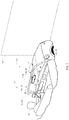
- the disclosure provides for a display system 10 for a vehicle 12.
- the display system 10 may be operable to display image data on a display screen 14.
- the display system 10 may comprise a focal distance correction feature 15 configured to adjust an apparent focal distance of the image data on the display screen 14 relative to an occupant 16 of the vehicle 12.
- the focal distance correction feature 15 may provide for relief of one or more forms of ocular strain, blurriness, and/or other various issues that may be associated with visual accommodation. In this way, the display system 10 provides for an improved viewing experience of the display screen 14.
- Visual accommodation is the process by which eyes focus on objects at various distances. For example, accommodation occurs when changing focus from a nearby object (e.g. the display screen 14) to a far off object in a distant region 20.
- the amplitude or effective accommodation of humans typically declines with age and may further be complicated by various additional visual irregularities.
- various visual disorders including, but not limited to latent hyperopia, myopia, presbyopia, and pseudomyopia, may be related to or have adverse effects that can further exacerbate issues with accommodation. Some of these visual disorders may be treated with corrective lenses, but such treatments may further compound the issues related to accommodation.
- the disclosure provides for the focal distance correction feature 15 configured to adjust the apparent focal distance of the display screen 14.
- the display screen 14 may be located in a passenger compartment 22 of the vehicle 12 nearby the occupant 16. Accordingly, one or more issues in accommodation may be apparent when the occupant 16 adjusts focal distance from the nearby display screen 14 to a distant region 20 away from the vehicle 12. For example, one or more images shown on the display screen 14 of the display system 10 may appear blurred when viewed after looking at the distant region 20. Such issues may not typically be associated with conventional rearview mirrors (e.g. reflective mirrors without video displays) because the objects in the mirror appear to have a similar focal distance to objects in the distant region 20.
- conventional rearview mirrors e.g. reflective mirrors without video displays
- Difficulties adjusting between the distant region 20 and nearby objects in the passenger compartment 22 may be more prevalent for older operators (e.g. the occupant 16) of the vehicle 12. Due to a gradual loss of accommodation, older individuals may commonly have greater difficultly changing focus from the distant region 20 to nearby objects (e.g. objects in the passenger compartment 22). As discussed herein, nearby objects may correspond to objects less than 750 mm from the occupant 16 (e.g. the display screen 14). The distant region 20 may correspond to distances greater than 2 m from the occupant 16. Accordingly, the occupant 16 may face challenges of eye strain as well as magnification correction when viewing nearby objects in the passenger compartment 22 while operating the vehicle 12.
- the disclosure may provide for the display system 10 incorporating a focal distance correction feature 15 to limit a difference in focal distance between the display screen 14 and one or more of far off objects in the distant region 20.
- the display system 10 may provide for improved visibility of a scene rearward from the vehicle 12 and limit eye strain that may otherwise result from adjustment or accommodation in focal distance from the display screen 14 to the distant region 20.
- the display system 10 may be configured to capture and display image data on the display screen 14.
- the image data may correspond to one or more scenes that may typically be visible in a rearview mirror.
- the display system 10 may provide for the display of panoramic image data captured by one or more cameras or imaging devices on the display screen 14. Accordingly, the disclosure provides for various embodiments of the display system, some of which are described in detail in the following description.
- the disclosure may provide for the display system 10 to generate and display augmented image data on the display screen 14.
- the augmented image data may be configured to be emitted or projected from the display screen 14 to provide occupant 16 with the perception that image data is projected behind the display screen and/or in front of the vehicle 12.
- the augmented image data may be restructured (e.g. stretched, elongated, manipulated, etc.) and projected through a lens apparatus 18 or lens array in connection with the display screen 14 in order to provide the perception of originating from behind the display screen 14.
- a projection distance q of the image data may be provided by the restructured or augmented image data emitted from the display screen 14 and passing through the lens apparatus 18 (e.g. one or more lenses, lens arrays, lenticular lenses, etc.).
- the lens apparatus 18 e.g. one or more lenses, lens arrays, lenticular lenses, etc.
- the augmented image data projected through the lens apparatus 18 may be visually perceived by the occupant 16 at the projected distance q due to a focal point and/or magnification of the lens apparatus 18 projecting the perceived focal depth behind the display screen 14.
- the lens apparatus 18 may be configured to adjust the focal depth of the display screen 14 such that a vergence angle of the binocular vision of the occupant 16 is expanded or increased to appear further away from the occupant 16 at the projected distance q.
- the image data may also be augmented by the display system 10 to correct for distortion attributed to viewing the image data through the lens apparatus 18. In this way, the system 10 may provide for an improved viewing experience of the image data on the display screen 14 by projecting the perceived distance of the image data to the projected distance q.
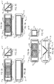
- FIGS. 2A-2C show an example of one implementation of a display apparatus 24.
- the display apparatus 24 is provided in an interior rearview assembly 26. Because the size of a housing of the rearview assembly 26 is not very large, it can be difficult to provide an object within the rearview assembly housing at a distance from the lens apparatus 18 sufficient to result in a projection of sufficient distance q to correct for accommodation. Accordingly, the display apparatus 24 includes a mirror apparatus such as a mirror 25 positioned between the lens apparatus 18 and the display screen 14 and the display screen 14 may be disposed in a plane perpendicular to the lens apparatus 18.
- the lens apparatus 18 may have a focal length of about 115 mm and a lens diameter of about 115 mm.
- the optical path is about 80 mm and the virtual image appears at a distance q of 125 mm from the lens apparatus 18, which represents a total distance from the eyes of the occupant 16 of about 750 mm (assuming a distance of about 500 mm from the eyes of the occupant 16 to the lens apparatus 18).
- the display system 10 may be configured to capture and display the image data or augmented image data on the display screen 14.
- the image data may comprise image data in the form of right eye image data or frames and left eye image data or frames.
- the right eye image data may be transmitted from the display screen 14 such that it is received by the right eye of the occupant 16.
- the left eye image data may be transmitted from the display screen 14 such that it is received by the left eye of the occupant 16.
- the display screen 14 may form a portion of a display apparatus 24 configured to project specific frames of the image data to each of the left eye and the right eye of the occupant 16.
- FIGS. 3A-3C show an example of another implementation of a display apparatus 24.
- the display apparatus 24 includes two lens apparatuses 18a and 18b rather than a single lens apparatus as in the implementation in FIGS. 2A-2C .
- the lenses are paired together to provide the driver a single (interpreted) complete image through both eyes, simultaneously.
- each lens apparatuses 18, 18a may have a focal length of about 115 mm and a lens diameter of about 75 mm.
- the optical path is about 80 mm and the virtual image appears at a distance q of 125 mm from the lens apparatus 18, which represents a total distance from the eyes of the occupant 16 of about 750 mm.
- FIGS. 4A-4C show an example of another implementation of a display apparatus 24.
- the display apparatus 24 includes two lens apparatuses 18a and 18b.
- This implementation further includes two separate display screens 14a and 14b disposed on opposite ends of the rearview assembly housing and a mirror apparatus including two mirrors 25a and 25b for reflecting respective images from display screens 14a and 14b towards respective lens apparatuses 18a and 18b.
- the image to be viewed by the driver is split in half with each half displayed by a respective one of the display screens 14a and 14b to provide the driver a single (interpreted) complete image through both eyes, simultaneously.
- each lens apparatuses 18, 18a may have a focal length of about 115 mm and a lens diameter of about 75 mm.
- the optical path is about 80 mm and the virtual image appears at a distance q of 125 mm from the lens apparatus 18, which represents a total distance from the eyes of the occupant 16 of about 750 mm.
- FIGS. 10A-10D show an example of another implementation of a display apparatus 24.
- the display apparatus 24 includes a display screen 14, a lens apparatus 18, and a mirror apparatus including a mirror 25 ( FIG. 10D ).
- the display screen 14 is positioned in a first plane that is not substantially orthogonal to a second plane in which the lens apparatus 18 is positioned and the emission direction of the display screen 14 is not orthogonal to the viewing direction.
- the display screen 14, lens apparatus 18, and the mirror 25 are disposed in a housing 29.
- the lens apparatus 18 is configured for mounting either directly to or proximate to the inside surface of a windshield of the vehicle.
- the housing 29 is configured such that the lens apparatus 18 has an outer surface that is substantially parallel to the inside surface of the windshield.
- This implementation differs in that it uses a lens with a 330 mm focal length.
- the optical path is about 250 mm and the virtual image appears at a distance q of 900 to 1000 mm from the lens apparatus 18, which represents a total distance from the eyes of the occupant 16 of about 1500 mm.
- a virtual image may be projected at a distance q of 1500 mm from the lens apparatus 18, which represents a total distance from the eyes of the occupant 16 of about 2000 mm.
- the mirrors 25, 25a, 25b are flat mirrors that may have a reflective coating on the surface facing the display screen(s) 14, 14a, 14b.
- the mirrors could also be curved to help facilitate select optical goals within the display system 10, such as (but not limited to) offsetting spherical aberrations within the lens, or altering the height, width or magnification of the generated virtual image.
- the lens apparatuses 18, 18a, 18b are shown as being Fresnel lenses. However, the lens apparatus may be a cylindrical lens or a lenticular lens.
- the implementations with multiple lens apparatuses and/or display screens may utilize image manipulation (or stitching) in order for the occupant to see a complete scene.
- the optical path length from the display screens 14, 14a, 14b to the lens apparatuses 18, 18a, 18b is substantially the same from each pixel of the display screens 14, 14a, 14b. This ensures clarity of the projected image.
- the lens apparatus 18 comprises a neutral display region 31 configured to transmit the image data from the display screen 14 and/or icons or elements incorporated in the display apparatus 24.
- the neutral display region 31 corresponds to an area, region, or zone of the lens apparatus 18 configured to transmit light (e.g. the image data) without optical correction.
- the image data emitted from the display screen 14 may be transmitted through the neutral display region 31 allowing the corresponding image data to "pass through” without substantial magnification or adjustment to the focal point such that the image data in the neutral display region 31 appears to originate from the display screen 14.
- the neutral display region 31 may provide for a first portion 14a of the display screen configured to display visual information that appears to be located on a plane formed by a surface of the lens apparatus 18 and a second portion 14b configured to display visual information that appears to originate from the projected distance q.
- the neutral display region 31 may provide for the display screen to provide for one or more soft keys, which may be displayed on the display screen 14 as buttons, icons, graphics and/or text in the plane of the display screen 14.
- the display apparatus 24 may comprise a user interface comprising a sensory grid or touchscreen functionality.
- the user interface may be utilized in combination with the soft keys transmitted through the neutral display region 31 to provide for a human-machine interface (HMI).
- HMI human-machine interface
- the display apparatus 24 may provide for the soft keys, buttons, text, or graphics to appear as though they originate from the display screen 14 through the neutral display region 31. Further discussion regarding the user interface is discussed in reference to FIG. 9 .
- the neutral display region 31 may be configured as a switchable optical correction mechanism, which may be referred to as a selective or switchable neutral display region.
- the switchable neutral display region may comprise a liquid crystal display (LCD) or various electro-optic elements that may be controlled by the system 10 to facilitate an "on demand" focal change feature.
- the switchable neutral display region may shift or apply a correction to the image data emitted from the display screen 14 such that the image data appears to originate from the projected distance q.
- the switchable neutral display region may function as the neutral display region 31 allowing the corresponding image data to "pass through” without substantial magnification or adjustment to the focal point such that the image data in the neutral display region 31 appears to originate from the display screen 14.
- the display apparatus 24 may comprise similar features to an autostereoscopic or automultiscopic display.
- the following references may include various implementations for display systems and camera systems configured to provide for autostereoscopic and/or automultiscopic functionality: U.S. Patent No. 9,179,134 B2, entitled “MULTI-LAYER PLENOPTIC DISPLAYS THAT COMBINE MULTIPLE EMISSIVE AND LIGHT MODULATING PLANES,” filed November 27, 2012, by Ranieri et al. ; U.S. Publication No. 2015/0334379 A1, entitled “DISPLAY UNIT FOR ROTATABLY DISPLAYING AN AUTOSTEREOSCOPIC PRESENTATION,” filed June 23, 2015, by Du et al. ; U.S.
- Patent No. 6,377,295 B1 entitled “OBSERVER TRACKING DIRECTIONAL DISPLAY,” filed August 12, 1997, by Woodgate et al.
- U.S. Publication No. 2015/0319423 A1 entitled “MULTI-PERSPECTIVE STEREOSCOPY FROM LIGHT FIELDS,” filed July 15, 2015, by Kim et al.
- U.S. Publication No. 2014/0125783 A1 entitled “AUTOSTEREOSCOPIC IMAGE DISPLAY AND METHOD FOR DRIVING THE SAME,” filed November 6, 2013, by Chung et al. ;
- the display system 10 may be configured to generate separate images for the right eye and the left eye of the occupant 16. Additionally, the display system 10 may be configured to generate a plurality of views that may be associated with a plurality of image sensors. Embodiments of the display system 10 configured to provide for a plurality of views may utilize one or more stereoscopic display methods to communicate the image data to the left eye and the right eye independently. In this configuration, the display apparatus 24 may provide for views that may normally be shown on a rearview mirror and conventional side mirrors.
- the display apparatus may be configured to track the position of the occupant 16 in the passenger compartment 22.
- the display apparatus 24 may comprise a sensor configured to track a location of a face and/or the eyes of the occupant 16.
- the display apparatus 24 may be operable to track a position of the eyes of the occupant 16 to control specific pixels in a pixel array configured to target the left eye or the right eye.
- the eyes of the operator may be tracked by one or more tracking sensors that may be incorporated in a display apparatus 24. An example of a tracking sensor is discussed further in reference to FIG. 9 .
- the display apparatus 24 of the display system 10 is incorporated in an interior rearview assembly 26.
- the display apparatus 24 may be mounted or otherwise attached to a vehicle 12 in a variety of locations.
- the display apparatus 24 may be integrated into a gauge cluster 27, a dashboard 28, a center stack 30 (e.g., infotainment center), side mirrors, and/or a headliner of the vehicle 12.
- the display apparatus 24 may be located in other peripheral locations.
- the display apparatus 24 may be mounted to a visor.
- the display apparatus 24 may be mounted to other surfaces of a vehicle 12 (e.g. windshield, door panel, or other vehicle components).
- a diagram of an imaging apparatus 32 of the vehicle 12 is shown.
- a plurality of image sensors 33 of the imaging apparatus 32 may correspond to a first image sensor C1, a second image sensor C2, and a third image sensor C3.
- Each of the image sensors 33 may have a field of view 34 focusing on an environment proximate the vehicle 12.
- the image sensors C1-C3 may be implemented to provide views of the environment proximate the vehicle 12 that may be displayed on the display screen 14 or any form of display device.
- the image sensors 33 may be arranged in various locations on the vehicle 12. In an exemplary embodiment, the image sensors 33 may be arranged such that each of a plurality of fields of view 34 of the image sensors C1-C3 is configured to capture a significantly different portion of the surrounding environment.
- Each of the image sensors 33 may comprise any form of device configured to capture image data, for example Charge Coupled Device (CCD) and Complementary Metal Oxide Semiconductor (CMOS) image sensors. Though three image sensors C1, C2, and C3 are discussed in reference to the present implementation, the number of image sensors may vary based on the specifications of the particular image sensors and/or a desired number of fields of view 34 for the display system 10.
- the image sensors C1, C2, and C3 are disposed on the vehicle 12 and oriented such that each field of view 34 of the image sensors 33 is directed toward a substantially different region.
- a first image sensor C1 may be disposed centrally on a rear facing portion of the vehicle 12 proximate a tailgate or similar area of the vehicle 12. In some embodiments, the image sensor C1 may be disposed proximate a rear bumper and/or a center high mount stop light (CHMSL).
- a second image sensor C2 and a third image sensor C3 may be disposed on a passenger's side 36 and a driver's side 38 of the vehicle 12, respectively. The second image sensor C2 and the third image sensor C3 may be configured to capture image data corresponding to the environment proximate the side regions of the vehicle 12.
- the second image sensor C2 and the third image sensor C3 may be disposed in side mirrors 40 of the vehicle 12.
- the image sensors C2 and C3, in combination with the first image sensor C1, may be configured to capture image data corresponding to a rearward-directed region relative the forward direction of the vehicle 12.
- the image sensors 33 may be configured to capture an increased or decreased viewing angle depending on the particular application.
- the image sensors may be configured to capture approximately the entire environment surrounding the vehicle 12.
- the image sensors 33 may be in communication with the image processor configured to process image data from each of the fields of view 34 captured by the image sensors 33.
- the image processor may be configured to generate augmented image data from the fields of view 34 for each of the right eye and the left eye of the occupant 16.
- the display system 10 may provide for an enhanced viewing experience by controlling the image data to provide a visual perception for the occupant that the image data originates from behind the display screen 24 at a projected distance q.
- the display system 10 may be utilized in various portions of the vehicle (e.g. a vehicle console, gage cluster, side mirrors, etc.). As such, the disclosure provides for various embodiments of vehicle displays that may be utilized for a variety of applications.
- the image processor may receive image data from one or more of the image sensors C1, C2, and C3 and encode or process the image data for demonstration on the display screen 14.
- the first image sensor C1 may provide for a first view (VIEW 1)
- the second image sensor C2 may provide for a second view (VIEW 2)
- the third image sensor C3 may provide for a third view (VIEW 3).
- the image views may be processed by the image processor, which may comprise each of the views being cropped, enhanced, stitched, and/or composited for display on the display screen 14 (42).
- the image data received from the image processor may further be processed according to one or more augmentation or correction algorithms to generate augmented image data 50.
- the augmented image data 50 may comprise a right image augmentation 44 and a left image augmentation 46.
- the augmentation or processing of the image data may comprise restructuring of various portions or segments of the image data to correct for a distortion of the lens apparatus 18 and/or facilitate lateral movement of the focal point of the eyes of the occupant 16.
- the augmentation or processing of the image data may comprise parsing segments or portions of the image data such that the augmented image data has an appropriate amount of overlap to facilitate lateral movement of the focal point to facilitate the image data to be perceived at the projected distance q after being transmitted through the lens apparatus.
- the processing or augmentation may result in a grid-like restructuring or stretching of the image data in the vertical and horizontal display dimensions.
- display system 10 may provide the perception of the image data projected from the display screen 14 to appear as though it is originating from behind the display screen 14, while also correcting for a distortion caused by the projection.
- the augmented image data 50 from the display screen 14 may be emitted from the display screen 14 into the lens apparatus 18.
- the image data may then be projected to the occupant 16 projected image data 52.
- the projected image data 52 may comprise right image data 54 and left image data 56.
- the display apparatus 24 may be configured to display the image data within the passenger compartment 22 having an appearance of originating from the projected distance q.
- the projected distance q may vary based on the desired design and configuration of the display apparatus 24.
- the projected distance q or the display distance may be about 125 mm to about 500 mm or more, and may be adjusted to greater than a meter.
- the focal point of the lens apparatus 18 (or lens array) may be defined as being located at optical infinity.
- the system 10 may be operable to generate image data for an autostereoscopic display.
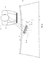
- the display apparatus 24 is shown projecting the right image data 54 and the left image data 56 in order to provide for independent correction of the augmented image data 50 for a right eye 62 and a left eye 64 of the occupant 16.
- the display system 10 may be configured to communicate right image data 54 to the right eye 62 and left image data 56 to the left eye 64.
- the display apparatus 24 may correspond to an autostereoscopic display device configured to project the right image data 54 to the right eye 62 and the left image data 56 to the left eye 64. In this configuration, the display system 10 may communicate the image data to the occupant to provide the perception that the image data originates at the projected distance q.
- the display apparatus 24 is shown in reference to a windshield 70 of the vehicle 12.
- the display apparatus 24 may comprise a display panel 72 corresponding to a pixel array 74 and a lenticular lens 76 formed on the display panel 72.
- a rear surface of the display screen 14 may face the lenticular lens 76.
- the display panel 72 may be a variety of display types having the pixel array 74, which may be arranged in rows and columns.
- the display panel 72 may correspond to a liquid crystal display (LCD), a plasma display, an organic light emitting diode (OLED) display, a field emission display (FED) panel, or various other displays.
- LCD liquid crystal display
- OLED organic light emitting diode
- FED field emission display
- the lenticular lens 76 may comprise long cylindrical lens elements 78.
- the lens elements 78 may be arranged in parallel and be aligned with the columns of the pixel array 74. Accordingly, the lenticular lens 76 may be disposed over the display panel 72.
- the lenticular lens 76 may separate the right image data 54 from the left image data 56 based on a location of each pixel relative to the cylindrical elements 78. In this way, the display apparatus 24 may be configured to direct the right image data 54 to the right eye 62 and the left image data 56 to the left eye 64.
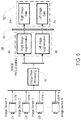
- the display system 10 may include a user interface 102 in the form of one or more buttons in communication with a control circuit 104.
- the user interface may provide for the display system 10 to receive one or more inputs to control operational settings, some of which are discussed herein.
- An exemplary embodiment of the display apparatus 24 may incorporate the elements shown in the dashed line box designated as the display apparatus 24.
- the user interface 102 may include input devices such as touchscreen displays, switches, microphones, knobs, touch sensor (e.g., projected capacitance sensor resistance-based touch sensor, resistive touch sensor, or other touch sensor), proximity sensors (e.g., projected capacitance, infrared, ultrasound, infrared, or other proximity sensor), or other hardware configured to generate an input from a user action.
- input devices such as touchscreen displays, switches, microphones, knobs, touch sensor (e.g., projected capacitance sensor resistance-based touch sensor, resistive touch sensor, or other touch sensor), proximity sensors (e.g., projected capacitance, infrared, ultrasound, infrared, or other proximity sensor), or other hardware configured to generate an input from a user action.
- touch sensor e.g., projected capacitance sensor resistance-based touch sensor, resistive touch sensor, or other touch sensor
- proximity sensors e.g., projected capacitance, infrared, ultrasound, infrared, or other proximity sensor
- the display system 10 may comprise the display apparatus 24.
- the display apparatus 24 may comprise the display panel 72 comprising the pixel array 74 and a lenticular lens 76 proximate the display panel 72.
- the display panel 72 may be a variety of display types having the pixel array 74, which may be arranged in rows and columns.
- the display panel 72 may correspond to a liquid crystal display (LCD), a plasma display, an organic light emitting diode (OLED) display, a field emission display (FED) panel, or various other displays.
- the display apparatus 24 may further incorporate a speaker, haptic feedback device (e.g., vibration motor), LEDs, or other hardware component for providing an output.
- haptic feedback device e.g., vibration motor
- the control circuit 104 may include various types of control circuitry, digital and/or analog, and may include a microprocessor, microcontroller, application-specific integrated circuit (ASIC), graphics processing unit (GPU), or other circuitry configured to perform various input/output, control, analysis, and other functions to be described herein.
- the control circuit 104 may be a system on a chip (SoC) individually or with additional hardware components described herein.
- the control circuit 104 may further include memory 106 (e.g., random access memory, read only memory, flash memory, hard disk storage, flash memory storage, solid state drive memory, etc.).
- the control circuit 104 may function as a controller for one or more hardware components included in the display system 10.
- the control circuit 104 may function as a controller for a touchscreen display or other operator input device, a controller for a transceiver, transmitter, receiver, or other communication device (e.g., implement a Bluetooth communications protocol).
- control circuit 104 may be configured to receive inputs from the user interface 102.
- the inputs may be converted into control signals that may be identified and utilized to output one or more control signals and/or transmit data.
- the display system 10 may communicate (e.g. send and/or receive signals and/or data) to control various functions of the display or settings or functions of the vehicle 12.
- the memory 106 may be used to facilitate the functions of the display system 10 as described herein.
- Memory 106 may include computer code modules, data, computer instructions, or other information which may be executed by the control circuit 104 or otherwise facilitate the functions of the display system 10 described herein.
- memory 106 may include encryption codes, pairing information, identification information, a device registry configuration, image augmentation information, etc.
- the memory 106 and/or the control circuit 104 may facilitate the functions described herein using one or more programming techniques, data manipulation techniques, and/or processing techniques such as using algorithms, routines, lookup tables, arrays, searching, databases, comparisons, instructions, etc.
- the display system 10 may further comprise a communication circuit 108.
- the communication circuit 108 may correspond to a transceiver circuit or transmitter circuit coupled to the control circuit 104.
- the transceiver circuit may provide for the display system 10 to transmit and/or receive wireless communication signals.
- the wireless communication signals may be transmitted to or received from a variety of wireless devices (e.g., an original transmitter, home electronic device, mobile communications device, and/or remote device).
- the communication circuit 108 may be controlled by the control circuit 104.
- the control circuit 104 may turn on or off the communication circuit 108, the control circuit 104 may send data using the communication circuit 108, format information, an activation signal, control signal, and/or other signal or data for transmission via the communication circuit 108, or otherwise control the communication circuit 108.
- Inputs from the communication circuit 108 may also be received by the control circuit 104.
- software configurations, updates, user settings and other information may be received by the communication circuit 108 and stored in the memory 106 by the control circuit 104.
- the control circuit 104 may be also coupled to a network adapter 110, receivers, and/or transmitters.
- the network adapter 110 may be configured to communicate with the image sensors 33.
- the network adapter 110 may be or include a cellular transceiver.
- the display system 10 may use the network adapter 110 and/or an additional transceiver (e.g., a cellular transceiver) to access the internet, other networks, and/or network hardware.
- the display system 10 may access the internet, other networks, and/or network hardware through an intermediate device in communication with the display system 10 such as the mobile device.
- the network adapter 110 may be configured to send/receive data and/or control signals to a mobile device.
- the network adapter 110 may communicate via various wireless communication protocols.
- communication protocols may include but are not limited to Bluetooth TM (e.g., a Bluetooth low energy (BLE), Wi-Fi (IEEE 802.11), ZigBee, cellular, etc.), a wired interface and/or protocol (e.g., Ethernet, universal serial bus (USB), Firewire, etc.), or other communications connection (e.g. infrared, optical, ultrasound, etc.).
- Bluetooth TM e.g., a Bluetooth low energy (BLE), Wi-Fi (IEEE 802.11), ZigBee, cellular, etc.
- a wired interface and/or protocol e.g., Ethernet, universal serial bus (USB), Firewire, etc.
- other communications connection e.g. infrared, optical, ultrasound, etc.
- the display system 10 may track a position of the occupant 16 or a viewer (e.g. a position of the eyes of the occupant 16) with the tracking sensor 112.
- the tracking sensor 112 may be implemented as an ultrasound sensor, an infrared sensor, a camera sensor/imager, a heat detector, etc.
- the tracking sensor 112 may identify a position of the occupant 16 such that an image processor 115 may generate views of image data (e.g. the augmented image data) from the image sensors 33.
- the augmented image data 50 may correspond to views that appear to the occupant 16 as though they are projected at the projected distance q.
- the display system 10 may comprise a position sensor 114 configured to identify a position or orientation of the display apparatus 24 relative to a forward direction of the vehicle 12.
- the position sensor 114 may correspond to an electrical or electromechanical sensor (e.g. an encoder, potentiometer, proximity sensor, compass, gyroscope, etc.), and may be configured to identify an angle of the display apparatus 24 or the display screen 14 relative to the forward direction of the vehicle 12.
- the image processor 115 may be operable to process the image data to select a plurality of views to generate the image data based on the angle of the display screen 14.
- the control circuit 104 may be in communication with a vehicle control module 116 via a communication bus 118 of the vehicle 12.
- the communication bus 118 may be configured to deliver signals to the control circuit 104 identifying various states of the vehicle 12.
- the communication bus 118 may be configured to communicate an operating condition of the vehicle (e.g. the ignition is active, a gear selection, a lighting activation or setting, etc.), an ambient light level, a seat occupancy, a door ajar signal, driver/occupant identity or any other information or control signals that may be communicated via the communication bus 118.
- the control circuit 104 may communicate with the vehicle control module 116 to identify a variety of conditions and/or settings of the vehicle 12.
- the display system 10 may be incorporated to display similar to those disclosed in the following references.
- Examples of display assemblies that may be utilized with the disclosure may include U.S. Patent Nos. 6,572,233 "REARVIEW MIRROR WITH DISPLAY,” filed September 18, 2000 ; 8,237,909 entitled “VEHICULAR REARVIEW MIRROR ASSEMBLY INCLUDING INTEGRATED BACKLIGHTING FOR A LIQUID CRYSTAL DISPLAY (LCD),” filed February 6, 2009 ; 8,411,245 “MULTI-DISPLAY MIRROR SYSTEM AND METHOD FOR EXPANDED VIEW AROUND A VEHICLE,” filed September 30, 2009 ; and 8,339,526 “VEHICLE REARVIEW MIRROR ASSEMBLY INCLUDING A HIGH INTENSITY DISPLAY,” filed March 9, 2007 .
- a display may similarly be incorporated in a vehicle forward center console, as a heads-up display, or in any other location that may be visible to an operator or occupant 16 of the vehicle 12.
- the term "coupled” in all of its forms, couple, coupling, coupled, etc. generally means the joining of two components (electrical or mechanical) directly or indirectly to one another. Such joining may be stationary in nature or movable in nature. Such joining may be achieved with the two components (electrical or mechanical) and any additional intermediate members being integrally formed as a single unitary body with one another or with the two components. Such joining may be permanent in nature or may be removable or releasable in nature unless otherwise stated.
- elements shown as integrally formed may be constructed of multiple parts or elements shown as multiple parts may be integrally formed, the operation of the interfaces may be reversed or otherwise varied, the length or width of the structures and/or members or connector or other elements of the system may be varied, the nature or number of adjustment positions provided between the elements may be varied.
- the elements and/or assemblies of the system may be constructed from any of a wide variety of materials that provide sufficient strength or durability, in any of a wide variety of colors, textures, and combinations. Accordingly, all such modifications are intended to be included within the scope of the present innovations.
Landscapes
- Engineering & Computer Science (AREA)
- Multimedia (AREA)
- Physics & Mathematics (AREA)
- Mechanical Engineering (AREA)
- Signal Processing (AREA)
- Optics & Photonics (AREA)
- General Physics & Mathematics (AREA)
- Chemical & Material Sciences (AREA)
- Combustion & Propulsion (AREA)
- Transportation (AREA)
- Controls And Circuits For Display Device (AREA)
- Fittings On The Vehicle Exterior For Carrying Loads, And Devices For Holding Or Mounting Articles (AREA)
- Closed-Circuit Television Systems (AREA)
- Instrument Panels (AREA)
Description
- The present invention generally relates to display devices for vehicles and more particularly to display devices configured to generate image data for ease of viewing a vehicular display.
- Such a display device is, for example, described in
WO 2016/170191 A1 representing the closest prior art. This document discloses a display system for a vehicle for displaying first images captured by at least one image sensor to a driver of the vehicle, the display system comprising: a first display screen configured to emit the first images in a first emission direction; a mirror apparatus configured to reflect the first images from the first display screen towards a viewing direction; and a first lens apparatus configured to receive the first images from the mirror apparatus, wherein the first lens apparatus: is configured to project the first images to a focal distance substantially opposite the viewing direction, and a rearview assembly housing containing the first display screen, the mirror apparatus, and the first lens apparatus disposed therein, wherein the focal distance is positioned at least about 750 mm from eyes of the driver, and the distance from the eyes of the driver to the first lens apparatus is about 500 mm. - The present invention is specified in the independent claim.
- Preferred embodiments result from the dependent claims.
- The present invention, advantages, and objects of the present invention will be further understood and appreciated by those skilled in the art by reference to the following specification, claims, and appended drawings.
- In the drawings:
-
FIG. 1 is projected view demonstrating a display system of a vehicle; -
FIG. 2A is a front elevational view of a rearview assembly incorporating a display apparatus of the display system ofFIG. 1 ; -
FIG. 2B is a cross-sectional plan view of the rearview assembly ofFIG. 2A ; -
FIG. 2C is a cross-sectional side view of the rearview assembly ofFIGS. 2A and 2B ; -
FIG. 3A is a front elevational view of a variation of the rearview assembly ofFIG. 2A ; -
FIG. 3B is a cross-sectional plan view of the rearview assembly ofFIG. 3A ; -
FIG. 3C is a cross-sectional side view of the rearview assembly ofFIGS. 3A and 3B ; -
FIG. 4A is a front elevational view of a variation of the rearview assembly ofFIG. 3A ; -
FIG. 4B is a cross-sectional plan view of the rearview assembly ofFIG. 4A ; -
FIG. 4C is a cross-sectional side view of the rearview assembly ofFIGS. 4A and 4B ; -
FIG. 5 is an elevational view of a vehicle demonstrating an imaging apparatus of a vehicle; -
FIG. 6 is a block diagram of an image processing method for generating augmented image data; -
FIG. 7 is a schematic diagram of an image processing method for an occupant of a vehicle; -
FIG. 8 is a top schematic view of a vehicle occupant viewing image data; -
FIG. 9 is a block diagram of a display system in accordance with the disclosure; -
FIG. 10A is a perspective view of another implementation of a display apparatus of the display system ofFIG. 1 ; -
FIG. 10B is a front elevational view of the display apparatus ofFIG. 10A ; -
FIG. 10C is a side elevational view of the display apparatus ofFIGS. 10A and 10B ; and -
FIG. 10D is cross-sectional side view of the display apparatus ofFIGS. 10A-10C taken along line XA-XA inFIG. 10B . - For purposes of description herein, the terms "upper," "lower," "right," "left," "rear," "front," "vertical," "horizontal," and derivatives thereof shall relate to the invention as oriented in
FIG. 1 . Unless stated otherwise, the term "front" shall refer to the surface of the element closer to an intended viewer of a display, and the term "rear" shall refer to the surface of the element further from the intended viewer of the display. However, it is to be understood that the invention may assume various alternative orientations, except where expressly specified to the contrary. It is also to be understood that the specific devices and processes illustrated in the attached drawings, and described in the following specification are simply exemplary embodiments of the inventive concepts defined in the appended claims. Hence, specific dimensions and other physical characteristics relating to the embodiments disclosed herein are not to be considered as limiting, unless the claims expressly state otherwise. - The terms "including," "comprises," "comprising," or any other variation thereof, are intended to cover a non-exclusive inclusion, such that a process, method, article, or apparatus that comprises a list of elements does not include only those elements, but may include other elements not expressly listed or inherent to such process, method, article, or apparatus. An element preceded by "comprises a ..." does not, without more constraints, preclude the existence of additional identical elements in the process, method, article, or apparatus that comprises the element.
- Referring to
FIG. 1 , the disclosure provides for adisplay system 10 for avehicle 12. Thedisplay system 10 may be operable to display image data on adisplay screen 14. In some embodiments, thedisplay system 10 may comprise a focal distance correction feature 15 configured to adjust an apparent focal distance of the image data on thedisplay screen 14 relative to anoccupant 16 of thevehicle 12. The focaldistance correction feature 15 may provide for relief of one or more forms of ocular strain, blurriness, and/or other various issues that may be associated with visual accommodation. In this way, thedisplay system 10 provides for an improved viewing experience of thedisplay screen 14. - Visual accommodation is the process by which eyes focus on objects at various distances. For example, accommodation occurs when changing focus from a nearby object (e.g. the display screen 14) to a far off object in a
distant region 20. The amplitude or effective accommodation of humans typically declines with age and may further be complicated by various additional visual irregularities. For example, various visual disorders including, but not limited to latent hyperopia, myopia, presbyopia, and pseudomyopia, may be related to or have adverse effects that can further exacerbate issues with accommodation. Some of these visual disorders may be treated with corrective lenses, but such treatments may further compound the issues related to accommodation. In order to limit the visual strain related to accommodation and related issues, the disclosure provides for the focaldistance correction feature 15 configured to adjust the apparent focal distance of thedisplay screen 14. - As demonstrated in
FIG. 1 , thedisplay screen 14 may be located in apassenger compartment 22 of thevehicle 12 nearby theoccupant 16. Accordingly, one or more issues in accommodation may be apparent when theoccupant 16 adjusts focal distance from thenearby display screen 14 to adistant region 20 away from thevehicle 12. For example, one or more images shown on thedisplay screen 14 of thedisplay system 10 may appear blurred when viewed after looking at thedistant region 20. Such issues may not typically be associated with conventional rearview mirrors (e.g. reflective mirrors without video displays) because the objects in the mirror appear to have a similar focal distance to objects in thedistant region 20. - Difficulties adjusting between the
distant region 20 and nearby objects in thepassenger compartment 22 may be more prevalent for older operators (e.g. the occupant 16) of thevehicle 12. Due to a gradual loss of accommodation, older individuals may commonly have greater difficultly changing focus from thedistant region 20 to nearby objects (e.g. objects in the passenger compartment 22). As discussed herein, nearby objects may correspond to objects less than 750 mm from the occupant 16 (e.g. the display screen 14). Thedistant region 20 may correspond to distances greater than 2 m from theoccupant 16. Accordingly, theoccupant 16 may face challenges of eye strain as well as magnification correction when viewing nearby objects in thepassenger compartment 22 while operating thevehicle 12. - The disclosure may provide for the
display system 10 incorporating a focaldistance correction feature 15 to limit a difference in focal distance between thedisplay screen 14 and one or more of far off objects in thedistant region 20. In this way, thedisplay system 10 may provide for improved visibility of a scene rearward from thevehicle 12 and limit eye strain that may otherwise result from adjustment or accommodation in focal distance from thedisplay screen 14 to thedistant region 20. - As discussed herein, the
display system 10 may be configured to capture and display image data on thedisplay screen 14. The image data may correspond to one or more scenes that may typically be visible in a rearview mirror. In some embodiments, thedisplay system 10 may provide for the display of panoramic image data captured by one or more cameras or imaging devices on thedisplay screen 14. Accordingly, the disclosure provides for various embodiments of the display system, some of which are described in detail in the following description. - Still referring to
FIG. 1 , in some embodiments, the disclosure may provide for thedisplay system 10 to generate and display augmented image data on thedisplay screen 14. The augmented image data may be configured to be emitted or projected from thedisplay screen 14 to provideoccupant 16 with the perception that image data is projected behind the display screen and/or in front of thevehicle 12. The augmented image data may be restructured (e.g. stretched, elongated, manipulated, etc.) and projected through alens apparatus 18 or lens array in connection with thedisplay screen 14 in order to provide the perception of originating from behind thedisplay screen 14. In some embodiments, a projection distance q of the image data may be provided by the restructured or augmented image data emitted from thedisplay screen 14 and passing through the lens apparatus 18 (e.g. one or more lenses, lens arrays, lenticular lenses, etc.). - The augmented image data projected through the
lens apparatus 18 may be visually perceived by theoccupant 16 at the projected distance q due to a focal point and/or magnification of thelens apparatus 18 projecting the perceived focal depth behind thedisplay screen 14. For example, thelens apparatus 18 may be configured to adjust the focal depth of thedisplay screen 14 such that a vergence angle of the binocular vision of theoccupant 16 is expanded or increased to appear further away from theoccupant 16 at the projected distance q. In various embodiments, the image data may also be augmented by thedisplay system 10 to correct for distortion attributed to viewing the image data through thelens apparatus 18. In this way, thesystem 10 may provide for an improved viewing experience of the image data on thedisplay screen 14 by projecting the perceived distance of the image data to the projected distance q. -
FIGS. 2A-2C show an example of one implementation of adisplay apparatus 24. In this implementation, thedisplay apparatus 24 is provided in an interiorrearview assembly 26. Because the size of a housing of therearview assembly 26 is not very large, it can be difficult to provide an object within the rearview assembly housing at a distance from thelens apparatus 18 sufficient to result in a projection of sufficient distance q to correct for accommodation. Accordingly, thedisplay apparatus 24 includes a mirror apparatus such as amirror 25 positioned between thelens apparatus 18 and thedisplay screen 14 and thedisplay screen 14 may be disposed in a plane perpendicular to thelens apparatus 18. This provides a folded optical path that allows thedisplay screen 14 to be positioned sufficiently far from thelens apparatus 18 such that thelens apparatus 18 may focus the image of thedisplay screen 14 at an adequate distance q. In this implementation, thelens apparatus 18 may have a focal length of about 115 mm and a lens diameter of about 115 mm. With the configuration shown inFIGS. 2A-2C , the optical path is about 80 mm and the virtual image appears at a distance q of 125 mm from thelens apparatus 18, which represents a total distance from the eyes of theoccupant 16 of about 750 mm (assuming a distance of about 500 mm from the eyes of theoccupant 16 to the lens apparatus 18). - As discussed further in reference to
FIGS. 3A-3C, 4A-4C , and6-8 , thedisplay system 10 may be configured to capture and display the image data or augmented image data on thedisplay screen 14. The image data may comprise image data in the form of right eye image data or frames and left eye image data or frames. The right eye image data may be transmitted from thedisplay screen 14 such that it is received by the right eye of theoccupant 16. The left eye image data may be transmitted from thedisplay screen 14 such that it is received by the left eye of theoccupant 16. Accordingly, thedisplay screen 14 may form a portion of adisplay apparatus 24 configured to project specific frames of the image data to each of the left eye and the right eye of theoccupant 16. -
FIGS. 3A-3C show an example of another implementation of adisplay apparatus 24. In this implementation, thedisplay apparatus 24 includes twolens apparatuses FIGS. 2A-2C . By using two smaller lenses and shorter focal lengths than a mirror-sized lens would provide given the same packaging constraints, a larger viewing area may be achieved. Both of the driver's eyes see content through bothlenses FIGS. 3A-3C , the optical path is about 80 mm and the virtual image appears at a distance q of 125 mm from thelens apparatus 18, which represents a total distance from the eyes of theoccupant 16 of about 750 mm. -
FIGS. 4A-4C show an example of another implementation of adisplay apparatus 24. In this implementation, thedisplay apparatus 24 includes twolens apparatuses separate display screens mirrors display screens respective lens apparatuses display screens FIGS. 4A-4C , the optical path is about 80 mm and the virtual image appears at a distance q of 125 mm from thelens apparatus 18, which represents a total distance from the eyes of theoccupant 16 of about 750 mm. -
FIGS. 10A-10D show an example of another implementation of adisplay apparatus 24. Like the other implementations, in this implementation, thedisplay apparatus 24 includes adisplay screen 14, alens apparatus 18, and a mirror apparatus including a mirror 25 (FIG. 10D ). Unlike the other implementations, thedisplay screen 14 is positioned in a first plane that is not substantially orthogonal to a second plane in which thelens apparatus 18 is positioned and the emission direction of thedisplay screen 14 is not orthogonal to the viewing direction. Thedisplay screen 14,lens apparatus 18, and themirror 25 are disposed in ahousing 29. Thelens apparatus 18 is configured for mounting either directly to or proximate to the inside surface of a windshield of the vehicle. Thus, thehousing 29 is configured such that thelens apparatus 18 has an outer surface that is substantially parallel to the inside surface of the windshield. This implementation differs in that it uses a lens with a 330 mm focal length. With the configuration shown inFIGS. 10A-10D , the optical path is about 250 mm and the virtual image appears at a distance q of 900 to 1000 mm from thelens apparatus 18, which represents a total distance from the eyes of theoccupant 16 of about 1500 mm. By further reducing the size of thedisplay screen 14 and reducing the focal length of thelens apparatus 18 to about 250 mm in the implementation ofFIGS. 10A-10D , a virtual image may be projected at a distance q of 1500 mm from thelens apparatus 18, which represents a total distance from the eyes of theoccupant 16 of about 2000 mm. - In the above implementations of the
display apparatus 24, themirrors display system 10, such as (but not limited to) offsetting spherical aberrations within the lens, or altering the height, width or magnification of the generated virtual image. - The lens apparatuses 18, 18a, 18b are shown as being Fresnel lenses. However, the lens apparatus may be a cylindrical lens or a lenticular lens. The implementations with multiple lens apparatuses and/or display screens may utilize image manipulation (or stitching) in order for the occupant to see a complete scene.
- In the implementations shown, the optical path length from the display screens 14, 14a, 14b to the
lens apparatuses - According to the invention, the
lens apparatus 18 comprises aneutral display region 31 configured to transmit the image data from thedisplay screen 14 and/or icons or elements incorporated in thedisplay apparatus 24. Theneutral display region 31 corresponds to an area, region, or zone of thelens apparatus 18 configured to transmit light (e.g. the image data) without optical correction. In this configuration, the image data emitted from thedisplay screen 14 may be transmitted through theneutral display region 31 allowing the corresponding image data to "pass through" without substantial magnification or adjustment to the focal point such that the image data in theneutral display region 31 appears to originate from thedisplay screen 14. That is, theneutral display region 31 may provide for afirst portion 14a of the display screen configured to display visual information that appears to be located on a plane formed by a surface of thelens apparatus 18 and asecond portion 14b configured to display visual information that appears to originate from the projected distance q. - The
neutral display region 31 may provide for the display screen to provide for one or more soft keys, which may be displayed on thedisplay screen 14 as buttons, icons, graphics and/or text in the plane of thedisplay screen 14. For example, in some embodiments, thedisplay apparatus 24 may comprise a user interface comprising a sensory grid or touchscreen functionality. The user interface may be utilized in combination with the soft keys transmitted through theneutral display region 31 to provide for a human-machine interface (HMI). In this configuration, thedisplay apparatus 24 may provide for the soft keys, buttons, text, or graphics to appear as though they originate from thedisplay screen 14 through theneutral display region 31. Further discussion regarding the user interface is discussed in reference toFIG. 9 . - In some embodiments, the
neutral display region 31 may be configured as a switchable optical correction mechanism, which may be referred to as a selective or switchable neutral display region. In this configuration, the switchable neutral display region may comprise a liquid crystal display (LCD) or various electro-optic elements that may be controlled by thesystem 10 to facilitate an "on demand" focal change feature. Accordingly, in a first configuration, the switchable neutral display region may shift or apply a correction to the image data emitted from thedisplay screen 14 such that the image data appears to originate from the projected distance q. Additionally, in a second configuration, the switchable neutral display region may function as theneutral display region 31 allowing the corresponding image data to "pass through" without substantial magnification or adjustment to the focal point such that the image data in theneutral display region 31 appears to originate from thedisplay screen 14. - According to various embodiments, the
display apparatus 24 may comprise similar features to an autostereoscopic or automultiscopic display. The following references may include various implementations for display systems and camera systems configured to provide for autostereoscopic and/or automultiscopic functionality:U.S. Patent No. 9,179,134 B2, entitled "MULTI-LAYER PLENOPTIC DISPLAYS THAT COMBINE MULTIPLE EMISSIVE AND LIGHT MODULATING PLANES," filed November 27, 2012, by Ranieri et al. U.S. Publication No. 2015/0334379 A1, entitled "DISPLAY UNIT FOR ROTATABLY DISPLAYING AN AUTOSTEREOSCOPIC PRESENTATION," filed June 23, 2015, by Du et al. ;U.S. Patent No. 6,377,295 B1, entitled "OBSERVER TRACKING DIRECTIONAL DISPLAY," filed August 12, 1997, by Woodgate et al. ;U.S. Publication No. 2015/0319423 A1, entitled "MULTI-PERSPECTIVE STEREOSCOPY FROM LIGHT FIELDS," filed July 15, 2015, by Kim et al. ;U.S. Publication No. 2014/0125783 A1, entitled "AUTOSTEREOSCOPIC IMAGE DISPLAY AND METHOD FOR DRIVING THE SAME," filed November 6, 2013, by Chung et al. ;U.S. Patent No. 8,947,605 B2, entitled "IMAGE DATA PLACEMENT METHOD FOR A TIME MULTIPLEXED AUTOSTEREOSCOPIC DISPLAY," filed May 25, 2012, by Eichenlaub ; andU.S. Publication No. 2009/0282429 A1, entitled "VIEWER TRACKING FOR DISPLAYING THREE DIMENSIONAL VIEWS," filed May 7, 2008, by Olsson et al. - As discussed herein, the
display system 10 may be configured to generate separate images for the right eye and the left eye of theoccupant 16. Additionally, thedisplay system 10 may be configured to generate a plurality of views that may be associated with a plurality of image sensors. Embodiments of thedisplay system 10 configured to provide for a plurality of views may utilize one or more stereoscopic display methods to communicate the image data to the left eye and the right eye independently. In this configuration, thedisplay apparatus 24 may provide for views that may normally be shown on a rearview mirror and conventional side mirrors. - In some embodiments, the display apparatus may be configured to track the position of the
occupant 16 in thepassenger compartment 22. For example, thedisplay apparatus 24 may comprise a sensor configured to track a location of a face and/or the eyes of theoccupant 16. In this way, thedisplay apparatus 24 may be operable to track a position of the eyes of theoccupant 16 to control specific pixels in a pixel array configured to target the left eye or the right eye. The eyes of the operator may be tracked by one or more tracking sensors that may be incorporated in adisplay apparatus 24. An example of a tracking sensor is discussed further in reference toFIG. 9 . - According to the invention, the
display apparatus 24 of thedisplay system 10 is incorporated in an interiorrearview assembly 26. Thedisplay apparatus 24 may be mounted or otherwise attached to avehicle 12 in a variety of locations. For example, thedisplay apparatus 24 may be integrated into agauge cluster 27, adashboard 28, a center stack 30 (e.g., infotainment center), side mirrors, and/or a headliner of thevehicle 12. Thedisplay apparatus 24 may be located in other peripheral locations. For example, thedisplay apparatus 24 may be mounted to a visor. Thedisplay apparatus 24 may be mounted to other surfaces of a vehicle 12 (e.g. windshield, door panel, or other vehicle components). - Referring now to
FIG. 5 , a diagram of animaging apparatus 32 of thevehicle 12 is shown. In an exemplary embodiment, a plurality ofimage sensors 33 of theimaging apparatus 32 may correspond to a first image sensor C1, a second image sensor C2, and a third image sensor C3. Each of theimage sensors 33 may have a field ofview 34 focusing on an environment proximate thevehicle 12. In the various implementations discussed herein, the image sensors C1-C3 may be implemented to provide views of the environment proximate thevehicle 12 that may be displayed on thedisplay screen 14 or any form of display device. - The
image sensors 33 may be arranged in various locations on thevehicle 12. In an exemplary embodiment, theimage sensors 33 may be arranged such that each of a plurality of fields ofview 34 of the image sensors C1-C3 is configured to capture a significantly different portion of the surrounding environment. Each of theimage sensors 33 may comprise any form of device configured to capture image data, for example Charge Coupled Device (CCD) and Complementary Metal Oxide Semiconductor (CMOS) image sensors. Though three image sensors C1, C2, and C3 are discussed in reference to the present implementation, the number of image sensors may vary based on the specifications of the particular image sensors and/or a desired number of fields ofview 34 for thedisplay system 10. - The image sensors C1, C2, and C3 are disposed on the
vehicle 12 and oriented such that each field ofview 34 of theimage sensors 33 is directed toward a substantially different region. A first image sensor C1 may be disposed centrally on a rear facing portion of thevehicle 12 proximate a tailgate or similar area of thevehicle 12. In some embodiments, the image sensor C1 may be disposed proximate a rear bumper and/or a center high mount stop light (CHMSL). A second image sensor C2 and a third image sensor C3 may be disposed on a passenger'sside 36 and a driver'sside 38 of thevehicle 12, respectively. The second image sensor C2 and the third image sensor C3 may be configured to capture image data corresponding to the environment proximate the side regions of thevehicle 12. - In some implementations, the second image sensor C2 and the third image sensor C3 may be disposed in side mirrors 40 of the
vehicle 12. The image sensors C2 and C3, in combination with the first image sensor C1, may be configured to capture image data corresponding to a rearward-directed region relative the forward direction of thevehicle 12. In some embodiments, theimage sensors 33 may be configured to capture an increased or decreased viewing angle depending on the particular application. In some embodiments, the image sensors may be configured to capture approximately the entire environment surrounding thevehicle 12. - As discussed further in reference to
FIG. 6 , theimage sensors 33 may be in communication with the image processor configured to process image data from each of the fields ofview 34 captured by theimage sensors 33. The image processor may be configured to generate augmented image data from the fields ofview 34 for each of the right eye and the left eye of theoccupant 16. In this configuration, thedisplay system 10 may provide for an enhanced viewing experience by controlling the image data to provide a visual perception for the occupant that the image data originates from behind thedisplay screen 24 at a projected distance q. Though discussed in detail in reference to the interiorrearview assembly 26, thedisplay system 10 may be utilized in various portions of the vehicle (e.g. a vehicle console, gage cluster, side mirrors, etc.). As such, the disclosure provides for various embodiments of vehicle displays that may be utilized for a variety of applications. - Referring now to
FIGS. 6 and7 , diagrams of an image processing method that may be processed by the image processor are shown. The image processor may receive image data from one or more of the image sensors C1, C2, and C3 and encode or process the image data for demonstration on thedisplay screen 14. For example, the first image sensor C1 may provide for a first view (VIEW 1), the second image sensor C2 may provide for a second view (VIEW 2), and the third image sensor C3 may provide for a third view (VIEW 3). The image views may be processed by the image processor, which may comprise each of the views being cropped, enhanced, stitched, and/or composited for display on the display screen 14 (42). - The image data received from the image processor may further be processed according to one or more augmentation or correction algorithms to generate
augmented image data 50. In some embodiments, theaugmented image data 50 may comprise aright image augmentation 44 and aleft image augmentation 46. The augmentation or processing of the image data may comprise restructuring of various portions or segments of the image data to correct for a distortion of thelens apparatus 18 and/or facilitate lateral movement of the focal point of the eyes of theoccupant 16. For example, the augmentation or processing of the image data may comprise parsing segments or portions of the image data such that the augmented image data has an appropriate amount of overlap to facilitate lateral movement of the focal point to facilitate the image data to be perceived at the projected distance q after being transmitted through the lens apparatus. The processing or augmentation may result in a grid-like restructuring or stretching of the image data in the vertical and horizontal display dimensions. In this way,display system 10 may provide the perception of the image data projected from thedisplay screen 14 to appear as though it is originating from behind thedisplay screen 14, while also correcting for a distortion caused by the projection. - The
augmented image data 50 from thedisplay screen 14 may be emitted from thedisplay screen 14 into thelens apparatus 18. The image data may then be projected to theoccupant 16 projectedimage data 52. In some embodiments, the projectedimage data 52 may compriseright image data 54 and leftimage data 56. In this way, thedisplay apparatus 24 may be configured to display the image data within thepassenger compartment 22 having an appearance of originating from the projected distance q. The projected distance q may vary based on the desired design and configuration of thedisplay apparatus 24. For example, the projected distance q or the display distance may be about 125 mm to about 500 mm or more, and may be adjusted to greater than a meter. Additionally in some embodiments, the focal point of the lens apparatus 18 (or lens array) may be defined as being located at optical infinity. By providing the perception to theoccupant 16 that the image data originates from the projected distance q, thedisplay apparatus 24 may serve to limit or alleviate accommodation issues associated with viewing the nearby image data on thedisplay screen 14 and objects located in thedistant region 20. - As discussed herein, in some embodiments, the
system 10 may be operable to generate image data for an autostereoscopic display. Referring now toFIGS. 6 and7 , thedisplay apparatus 24 is shown projecting theright image data 54 and theleft image data 56 in order to provide for independent correction of theaugmented image data 50 for aright eye 62 and aleft eye 64 of theoccupant 16. Thedisplay system 10 may be configured to communicateright image data 54 to theright eye 62 and leftimage data 56 to theleft eye 64. As discussed herein, thedisplay apparatus 24 may correspond to an autostereoscopic display device configured to project theright image data 54 to theright eye 62 and theleft image data 56 to theleft eye 64. In this configuration, thedisplay system 10 may communicate the image data to the occupant to provide the perception that the image data originates at the projected distance q. - As shown in
FIG. 8 , thedisplay apparatus 24 is shown in reference to a windshield 70 of thevehicle 12. To provide such functionality, thedisplay apparatus 24 may comprise a display panel 72 corresponding to a pixel array 74 and a lenticular lens 76 formed on the display panel 72. A rear surface of thedisplay screen 14 may face the lenticular lens 76. The display panel 72 may be a variety of display types having the pixel array 74, which may be arranged in rows and columns. For example, the display panel 72 may correspond to a liquid crystal display (LCD), a plasma display, an organic light emitting diode (OLED) display, a field emission display (FED) panel, or various other displays. - The lenticular lens 76 may comprise long cylindrical lens elements 78. The lens elements 78 may be arranged in parallel and be aligned with the columns of the pixel array 74. Accordingly, the lenticular lens 76 may be disposed over the display panel 72. The lenticular lens 76 may separate the
right image data 54 from theleft image data 56 based on a location of each pixel relative to the cylindrical elements 78. In this way, thedisplay apparatus 24 may be configured to direct theright image data 54 to theright eye 62 and theleft image data 56 to theleft eye 64. - Referring now to
FIG. 9 , a block diagram of thedisplay system 10 is shown. Thedisplay system 10 may include auser interface 102 in the form of one or more buttons in communication with acontrol circuit 104. The user interface may provide for thedisplay system 10 to receive one or more inputs to control operational settings, some of which are discussed herein. An exemplary embodiment of thedisplay apparatus 24 may incorporate the elements shown in the dashed line box designated as thedisplay apparatus 24. In some embodiments, theuser interface 102 may include input devices such as touchscreen displays, switches, microphones, knobs, touch sensor (e.g., projected capacitance sensor resistance-based touch sensor, resistive touch sensor, or other touch sensor), proximity sensors (e.g., projected capacitance, infrared, ultrasound, infrared, or other proximity sensor), or other hardware configured to generate an input from a user action. - The
display system 10 may comprise thedisplay apparatus 24. Thedisplay apparatus 24 may comprise the display panel 72 comprising the pixel array 74 and a lenticular lens 76 proximate the display panel 72. The display panel 72 may be a variety of display types having the pixel array 74, which may be arranged in rows and columns. For example, the display panel 72 may correspond to a liquid crystal display (LCD), a plasma display, an organic light emitting diode (OLED) display, a field emission display (FED) panel, or various other displays. Thedisplay apparatus 24 may further incorporate a speaker, haptic feedback device (e.g., vibration motor), LEDs, or other hardware component for providing an output. - The
control circuit 104 may include various types of control circuitry, digital and/or analog, and may include a microprocessor, microcontroller, application-specific integrated circuit (ASIC), graphics processing unit (GPU), or other circuitry configured to perform various input/output, control, analysis, and other functions to be described herein. In other embodiments, thecontrol circuit 104 may be a system on a chip (SoC) individually or with additional hardware components described herein. Thecontrol circuit 104 may further include memory 106 (e.g., random access memory, read only memory, flash memory, hard disk storage, flash memory storage, solid state drive memory, etc.). In further embodiments, thecontrol circuit 104 may function as a controller for one or more hardware components included in thedisplay system 10. For example, thecontrol circuit 104 may function as a controller for a touchscreen display or other operator input device, a controller for a transceiver, transmitter, receiver, or other communication device (e.g., implement a Bluetooth communications protocol). - In some embodiments, the
control circuit 104 may be configured to receive inputs from theuser interface 102. The inputs may be converted into control signals that may be identified and utilized to output one or more control signals and/or transmit data. In this configuration, thedisplay system 10 may communicate (e.g. send and/or receive signals and/or data) to control various functions of the display or settings or functions of thevehicle 12. - The
memory 106 may be used to facilitate the functions of thedisplay system 10 as described herein.Memory 106 may include computer code modules, data, computer instructions, or other information which may be executed by thecontrol circuit 104 or otherwise facilitate the functions of thedisplay system 10 described herein. For example,memory 106 may include encryption codes, pairing information, identification information, a device registry configuration, image augmentation information, etc. Thememory 106 and/or thecontrol circuit 104 may facilitate the functions described herein using one or more programming techniques, data manipulation techniques, and/or processing techniques such as using algorithms, routines, lookup tables, arrays, searching, databases, comparisons, instructions, etc. - The
display system 10 may further comprise acommunication circuit 108. Thecommunication circuit 108 may correspond to a transceiver circuit or transmitter circuit coupled to thecontrol circuit 104. The transceiver circuit may provide for thedisplay system 10 to transmit and/or receive wireless communication signals. The wireless communication signals may be transmitted to or received from a variety of wireless devices (e.g., an original transmitter, home electronic device, mobile communications device, and/or remote device). Thecommunication circuit 108 may be controlled by thecontrol circuit 104. For example, thecontrol circuit 104 may turn on or off thecommunication circuit 108, thecontrol circuit 104 may send data using thecommunication circuit 108, format information, an activation signal, control signal, and/or other signal or data for transmission via thecommunication circuit 108, or otherwise control thecommunication circuit 108. Inputs from thecommunication circuit 108 may also be received by thecontrol circuit 104. For example, software configurations, updates, user settings and other information may be received by thecommunication circuit 108 and stored in thememory 106 by thecontrol circuit 104. - The
control circuit 104 may be also coupled to anetwork adapter 110, receivers, and/or transmitters. In some embodiments, thenetwork adapter 110 may be configured to communicate with theimage sensors 33. In some embodiments, thenetwork adapter 110 may be or include a cellular transceiver. In this configuration, thedisplay system 10 may use thenetwork adapter 110 and/or an additional transceiver (e.g., a cellular transceiver) to access the internet, other networks, and/or network hardware. In some embodiments, thedisplay system 10 may access the internet, other networks, and/or network hardware through an intermediate device in communication with thedisplay system 10 such as the mobile device. - In an exemplary embodiment, the
network adapter 110 may be configured to send/receive data and/or control signals to a mobile device. Thenetwork adapter 110 may communicate via various wireless communication protocols. For example, communication protocols may include but are not limited to Bluetooth™ (e.g., a Bluetooth low energy (BLE), Wi-Fi (IEEE 802.11), ZigBee, cellular, etc.), a wired interface and/or protocol (e.g., Ethernet, universal serial bus (USB), Firewire, etc.), or other communications connection (e.g. infrared, optical, ultrasound, etc.). - In some embodiments, the
display system 10 may track a position of theoccupant 16 or a viewer (e.g. a position of the eyes of the occupant 16) with the trackingsensor 112. The trackingsensor 112 may be implemented as an ultrasound sensor, an infrared sensor, a camera sensor/imager, a heat detector, etc. In general, the trackingsensor 112 may identify a position of theoccupant 16 such that animage processor 115 may generate views of image data (e.g. the augmented image data) from theimage sensors 33. Theaugmented image data 50 may correspond to views that appear to theoccupant 16 as though they are projected at the projected distance q. - In some embodiments, the
display system 10 may comprise aposition sensor 114 configured to identify a position or orientation of thedisplay apparatus 24 relative to a forward direction of thevehicle 12. Theposition sensor 114 may correspond to an electrical or electromechanical sensor (e.g. an encoder, potentiometer, proximity sensor, compass, gyroscope, etc.), and may be configured to identify an angle of thedisplay apparatus 24 or thedisplay screen 14 relative to the forward direction of thevehicle 12. In this way, theimage processor 115 may be operable to process the image data to select a plurality of views to generate the image data based on the angle of thedisplay screen 14. - The
control circuit 104 may be in communication with a vehicle control module 116 via a communication bus 118 of thevehicle 12. The communication bus 118 may be configured to deliver signals to thecontrol circuit 104 identifying various states of thevehicle 12. For example, the communication bus 118 may be configured to communicate an operating condition of the vehicle (e.g. the ignition is active, a gear selection, a lighting activation or setting, etc.), an ambient light level, a seat occupancy, a door ajar signal, driver/occupant identity or any other information or control signals that may be communicated via the communication bus 118. In this way, thecontrol circuit 104 may communicate with the vehicle control module 116 to identify a variety of conditions and/or settings of thevehicle 12. - In some embodiments, the
display system 10 may be incorporated to display similar to those disclosed in the following references. Examples of display assemblies that may be utilized with the disclosure may includeU.S. Patent Nos. 6,572,233 "REARVIEW MIRROR WITH DISPLAY," filed September 18, 2000 ;8,237,909 entitled "VEHICULAR REARVIEW MIRROR ASSEMBLY INCLUDING INTEGRATED BACKLIGHTING FOR A LIQUID CRYSTAL DISPLAY (LCD)," filed February 6, 2009 ;8,411,245 "MULTI-DISPLAY MIRROR SYSTEM AND METHOD FOR EXPANDED VIEW AROUND A VEHICLE," filed September 30, 2009 ; and8,339,526 "VEHICLE REARVIEW MIRROR ASSEMBLY INCLUDING A HIGH INTENSITY DISPLAY," filed March 9, 2007 . - The following references may include various implementations for imager systems providing rearward facing panoramic views:
U.S. Patent No. 8,237,909 B2, "VEHICLE REARVIEW MIRROR ASSEMBLY INCLUDING INTEGRATED BACKLIGHTING FOR A LIQUID CRYSTAL DISPLAY (LCD)," filed February 6, 2009 ; andU.S. Patent No. 8,411,245 "MULTI-DISPLAY MIRROR SYSTEM AND METHOD FOR EXPANDED VIEW AROUND A VEHICLE," filed September 30, 2009 . Though thedisplay system 10 in the various implementations disclosed herein is shown incorporated in a rearview display system, a display may similarly be incorporated in a vehicle forward center console, as a heads-up display, or in any other location that may be visible to an operator oroccupant 16 of thevehicle 12. - It will be understood by one having ordinary skill in the art that construction of the described invention and other components is not limited to any specific material. Other exemplary embodiments of the invention disclosed herein may be formed from a wide variety of materials, unless described otherwise herein.
- For purposes of this disclosure, the term "coupled" (in all of its forms, couple, coupling, coupled, etc.) generally means the joining of two components (electrical or mechanical) directly or indirectly to one another. Such joining may be stationary in nature or movable in nature. Such joining may be achieved with the two components (electrical or mechanical) and any additional intermediate members being integrally formed as a single unitary body with one another or with the two components. Such joining may be permanent in nature or may be removable or releasable in nature unless otherwise stated.
- It is also important to note that the construction and arrangement of the elements of the invention as shown in the exemplary embodiments is illustrative only. Although only a few embodiments of the present innovations have been described in detail in this disclosure, those skilled in the art who review this disclosure will readily appreciate that many modifications are possible (e.g., variations in sizes, dimensions, structures, shapes and proportions of the various elements, values of parameters, mounting arrangements, use of materials, colors, orientations, etc.) without materially departing from the novel teachings and advantages of the subject matter recited. For example, elements shown as integrally formed may be constructed of multiple parts or elements shown as multiple parts may be integrally formed, the operation of the interfaces may be reversed or otherwise varied, the length or width of the structures and/or members or connector or other elements of the system may be varied, the nature or number of adjustment positions provided between the elements may be varied. It should be noted that the elements and/or assemblies of the system may be constructed from any of a wide variety of materials that provide sufficient strength or durability, in any of a wide variety of colors, textures, and combinations. Accordingly, all such modifications are intended to be included within the scope of the present innovations.
- It will be understood that any described processes or steps within described processes may be combined with other disclosed processes or steps to form structures within the scope of the present invention. The exemplary structures and processes disclosed herein are for illustrative purposes and are not to be construed as limiting.
- It is also to be understood that variations and modifications can be made on the aforementioned structures and methods without departing from the concepts of the present invention, and further it is to be understood that such concepts are intended to be covered by the following claims unless these claims by their language expressly state otherwise.
Claims (15)
- A display system (10) for a vehicle (12) for displaying first images captured by at least one image sensor (33) to a driver of the vehicle (12), the display system (10) comprising:a first display screen (14, 14a) configured to emit the first images in a first emission direction;a mirror apparatus (25, 25a) configured to reflect the first images from the first display screen (14, 14a) towards a viewing direction; anda first lens apparatus (18, 18a) configured to receive the first images from the mirror apparatus (25, 25a), wherein the first lens apparatus (18, 18a):is configured to project the first images to a focal distance substantially opposite the viewing direction; andcomprises a neutral display region (31) configured to transmit visual information that appears to be located on a plane formed by a surface of the first lens apparatus (18, 18a); anda rearview assembly housing (29) containing the first display screen (14, 14a), the mirror apparatus (25, 25a), and the first lens apparatus (18, 18a) disposed therein, wherein:the focal distance is positioned at least about 750 mm from eyes of the driver, andthe distance from the eyes of the driver to the first lens apparatus (18, 18a) is about 500 mm.
- The display system (10) according to claim 1, wherein the focal distance is positioned at least about 1.5 m from the eyes of the driver.
- The display system (10) of any one of claims 1 and 2, wherein the display system (10) corresponds to a rearview video display apparatus.
- The display system (10) according to any one of claims 1-3, wherein the first lens apparatus (18, 18a) has a focal length of about 115 mm.
- The display system (10) according to any one of claims 1-4, and further comprising a second display screen (14b) configured to emit second images in a second emission direction.
- The display system (10) according to claim 5, wherein the first emission direction is the same as the second emission direction.
- The display system (10) according to claim 5, wherein the first emission direction is opposite the second emission direction.
- The display system (10) according to any one of claims 1-7, wherein the optical path length from the first display screen (14, 14a) to the first lens apparatus (18, 18a) is substantially the same from each pixel of the first display screen (14, 14a).
- The display system (10) according to any one of claims 1, 4, 6 or 7, the display system (10) further comprising:a second display screen (14b) configured to emit second images in a second emission direction;the mirror apparatus (25, 25a) positioned to reflect the first and second images from the first and second display screens (14, 14a, 14b) toward a viewing direction; anda second lens apparatus (18b) configured to receive the second images from the mirror apparatus (25, 25a), wherein the second lens apparatus (18b) is configured to project the second images to the focal distance substantially opposite the viewing direction.
- The display system (10) according to claim 9, wherein the first and second display screens (14, 14a, 14b) are disposed in parallel planes.
- The display system (10) according to any one of claims 9-10, wherein the mirror apparatus (25, 25a) comprises a first mirror (25a) positioned to reflect the first images from the first display screen (14, 14a) toward the viewing direction, and a second mirror (25b) positioned to reflect the second images from the second display screen (14b) toward the viewing direction.
- The display system (10) according to any one of claims 9-11, wherein the mirror apparatus (25, 25a) comprises a single planar mirror (25a) positioned to reflect the first and second images from the first and second display screens (14, 14a, 14b) toward the viewing direction.
- The display system (10) of any of claims 1-9 or 10-12, wherein the image data comprises right eye image data or frames and left eye image data or frames, wherein the right eye image data may be received by the right eye of the driver and the left eye image data may be received by the left eye of the driver.
- The display system (10) of any of claims 1-9, 10-12, or 13, wherein the neutral display region (31) is operable to provide for one or more soft keys.
- The display system (10) of any of claims 1 to 14, wherein the neutral display region (31) is configured as a switchable optical correction mechanism to facilitate an on demand focal change feature.
Applications Claiming Priority (2)
| Application Number | Priority Date | Filing Date | Title |
|---|---|---|---|
| US201762563914P | 2017-09-27 | 2017-09-27 | |
| PCT/IB2018/057517 WO2019064233A1 (en) | 2017-09-27 | 2018-09-27 | Full display mirror with accommodation correction |
Publications (3)
| Publication Number | Publication Date |
|---|---|
| EP3687860A4 EP3687860A4 (en) | 2020-08-05 |
| EP3687860A1 EP3687860A1 (en) | 2020-08-05 |
| EP3687860B1 true EP3687860B1 (en) | 2021-12-29 |
Family
ID=65807458
Family Applications (1)
| Application Number | Title | Priority Date | Filing Date |
|---|---|---|---|
| EP18860167.8A Active EP3687860B1 (en) | 2017-09-27 | 2018-09-27 | Full display mirror with accommodation correction |
Country Status (6)
| Country | Link |
|---|---|
| US (1) | US11092819B2 (en) |
| EP (1) | EP3687860B1 (en) |
| JP (1) | JP7129475B2 (en) |
| KR (1) | KR102557322B1 (en) |
| CN (1) | CN111225830B (en) |
| WO (1) | WO2019064233A1 (en) |
Families Citing this family (7)
| Publication number | Priority date | Publication date | Assignee | Title |
|---|---|---|---|---|
| US12179783B2 (en) * | 2019-09-03 | 2024-12-31 | Lg Electronics Inc. | Apparatus and method for providing extended function to vehicle |
| WO2021091968A1 (en) | 2019-11-07 | 2021-05-14 | Gentex Corporation | Display system with augmented focal point |
| DE102019220205A1 (en) * | 2019-12-19 | 2021-06-24 | Volkswagen Aktiengesellschaft | Adaptive adjustment of an optical output to the eyesight |
| WO2022138110A1 (en) * | 2020-12-24 | 2022-06-30 | 株式会社村上開明堂 | Display device for vehicles |
| WO2023152729A1 (en) * | 2022-02-14 | 2023-08-17 | Gentex Corporation | Imaging system for a vehicle |
| CN115742746A (en) * | 2022-11-30 | 2023-03-07 | 北京经纬恒润科技股份有限公司 | Vehicle-mounted interaction device and control method thereof |
| WO2025063343A1 (en) * | 2023-09-22 | 2025-03-27 | 엘지전자 주식회사 | Display device for vehicle |
Family Cites Families (64)
| Publication number | Priority date | Publication date | Assignee | Title |
|---|---|---|---|---|
| IT979201B (en) | 1973-02-16 | 1974-09-30 | Brichima Spa | PROCESS FOR THE PREPARATION OF DIPHENOLS |
| JPS5139209A (en) * | 1974-09-26 | 1976-04-01 | Kubota Ltd | AZEMORYOKONZUME |
| JP3031013B2 (en) * | 1991-11-15 | 2000-04-10 | 日産自動車株式会社 | Visual information providing device |
| JPH05147455A (en) * | 1991-11-29 | 1993-06-15 | Shimadzu Corp | Vehicle display device |
| EP0602934B1 (en) | 1992-12-17 | 1999-03-10 | Sharp Kabushiki Kaisha | Autostereoscopic directional display apparatus |
| JPH07140416A (en) * | 1993-09-27 | 1995-06-02 | Casio Comput Co Ltd | Head mounted display |
| US6501536B1 (en) | 1995-01-18 | 2002-12-31 | Ronald J. Fredricks | Method and apparatus for determining the location of an occupant of a vehicle |
| GB2317291A (en) | 1996-09-12 | 1998-03-18 | Sharp Kk | Observer tracking directional display |
| US6170956B1 (en) | 1998-10-14 | 2001-01-09 | Gentex Corporation | Rearview mirror with display |
| US8491118B2 (en) | 2001-11-07 | 2013-07-23 | Michael Waters | Lighted reading glasses |
| EP1639394A2 (en) | 2003-06-10 | 2006-03-29 | Elop Electro-Optics Industries Ltd. | Method and system for displaying an informative image against a background image |
| DE102005001973A1 (en) | 2005-01-15 | 2006-07-20 | Bayerische Motoren Werke Ag | Stereo combiner display for displaying image information e.g. text, in motor vehicle, has combiner arranged in field of view of vehicle driver, and image producing and separation units formed as transparent components of combiner |
| DE102005017313A1 (en) | 2005-04-14 | 2006-10-19 | Volkswagen Ag | Method for displaying information in a means of transport and instrument cluster for a motor vehicle |
| KR100727947B1 (en) | 2005-07-11 | 2007-06-14 | 삼성전자주식회사 | Stereoscopic image display device for 2D / 3D image compatibility |
| US20070035694A1 (en) | 2005-08-15 | 2007-02-15 | Keller Carolyn S | Light filtering nonprescription temporary reading glasses |
| JP5577038B2 (en) | 2006-03-09 | 2014-08-20 | ジェンテックス コーポレイション | Vehicle rear view assembly including high brightness display |
| CN101479130B (en) * | 2006-06-28 | 2012-05-30 | 约翰逊控制技术公司 | Vehicle vision system |
| US20100027417A1 (en) | 2006-06-29 | 2010-02-04 | Guido Franceschini | Method and apparatus for improving bandwith exploitation in real-time audio/video communications |
| US8009178B2 (en) | 2007-06-29 | 2011-08-30 | Microsoft Corporation | Augmenting images for panoramic display |
| WO2009026223A2 (en) | 2007-08-16 | 2009-02-26 | Gentex Corporation | Vehicle rearview assembly including a display for displaying video captured by a camera and user instructions |
| US20090282429A1 (en) | 2008-05-07 | 2009-11-12 | Sony Ericsson Mobile Communications Ab | Viewer tracking for displaying three dimensional views |
| JP2010066731A (en) * | 2008-09-12 | 2010-03-25 | Nippon Sheet Glass Co Ltd | Lens optical system, image display, and headup display |
| US8947605B2 (en) | 2008-11-07 | 2015-02-03 | Dimension Technologies, Inc. | Image data placement method for a time multiplexed autostereoscopic display |
| US8587639B2 (en) | 2008-12-11 | 2013-11-19 | Alcatel Lucent | Method of improved three dimensional display technique |
| JP5161760B2 (en) * | 2008-12-26 | 2013-03-13 | 株式会社東芝 | In-vehicle display system and display method |
| US8237909B2 (en) | 2009-02-06 | 2012-08-07 | Gentex Corporation | Vehicular rearview mirror assembly including integrated backlighting for a liquid crystal display (LCD) |
| US8411245B2 (en) | 2009-02-06 | 2013-04-02 | Gentex Corporation | Multi-display mirror system and method for expanded view around a vehicle |
| JP5278819B2 (en) | 2009-05-11 | 2013-09-04 | 株式会社リコー | Stereo camera device and vehicle exterior monitoring device using the same |
| WO2011047214A2 (en) | 2009-10-14 | 2011-04-21 | Optimum Technologies, Inc. | Portable retinal camera and image acquisition method |
| KR20120088754A (en) | 2009-11-21 | 2012-08-08 | 더글라스 피터 마기아리 | Head mounted display device |
| US20120092329A1 (en) | 2010-10-13 | 2012-04-19 | Qualcomm Incorporated | Text-based 3d augmented reality |
| US9179134B2 (en) | 2011-01-18 | 2015-11-03 | Disney Enterprises, Inc. | Multi-layer plenoptic displays that combine multiple emissive and light modulating planes |
| CN103609107B (en) | 2011-06-22 | 2016-06-01 | 皇家飞利浦有限公司 | There is the autostereoscopic display apparatus of optical amplifier |
| US9113043B1 (en) | 2011-10-24 | 2015-08-18 | Disney Enterprises, Inc. | Multi-perspective stereoscopy from light fields |
| US9648310B2 (en) | 2011-11-09 | 2017-05-09 | Qualcomm Incorporated | Systems and methods for mask adjustment in 3D display |
| JP5510431B2 (en) | 2011-11-21 | 2014-06-04 | 株式会社デンソー | Vehicle display device |
| US9321329B2 (en) | 2012-05-10 | 2016-04-26 | Chris Beckman | Glare elimination and image enhancement system improving lenses, windows and displays |
| US8711486B2 (en) | 2012-06-26 | 2014-04-29 | GM Global Technology Operations LLC | System for highlighting targets on head up displays with near focus plane |
| US20140114534A1 (en) | 2012-10-19 | 2014-04-24 | GM Global Technology Operations LLC | Dynamic rearview mirror display features |
| KR101981527B1 (en) | 2012-11-08 | 2019-05-23 | 엘지디스플레이 주식회사 | Autostereoscopic image display and driving method thereof |
| BR112015011996B1 (en) | 2012-12-24 | 2022-11-22 | Interdigital Madison Patent Holdings, Sas | COMPUTER READABLE NON-TRANSITORY STORAGE MEDIA AND ELECTRONIC APPARATUS FOR ROTATINGLY DISPLAYING AN AUTOSTEREOSCOPIC PRESENTATION |
| US9200960B2 (en) | 2013-04-26 | 2015-12-01 | Entanglement Technologies, Inc. | Cavity enhanced absorption spectroscopy with a laser modulation side-band frequency locked to the cavity |
| US20140327771A1 (en) | 2013-05-01 | 2014-11-06 | Nvidia Corporation | System, method, and computer program product for displaying a scene as a light field |
| US10349031B2 (en) | 2013-07-28 | 2019-07-09 | Michael J. DeLuca | Augmented reality based user interfacing |
| US9986225B2 (en) | 2014-02-14 | 2018-05-29 | Autodesk, Inc. | Techniques for cut-away stereo content in a stereoscopic display |
| DE102015202846B4 (en) | 2014-02-19 | 2020-06-25 | Magna Electronics, Inc. | Vehicle vision system with display |
| US9756319B2 (en) | 2014-02-27 | 2017-09-05 | Harman International Industries, Incorporated | Virtual see-through instrument cluster with live video |
| US9866669B2 (en) | 2014-03-03 | 2018-01-09 | Lg Electronics Inc. | Mobile device and method of controlling the same |
| DE102014205519A1 (en) | 2014-03-25 | 2015-10-01 | Robert Bosch Gmbh | Method and apparatus for adapting a display of an autostereoscopic display for a vehicle |
| US9428054B2 (en) | 2014-04-04 | 2016-08-30 | Here Global B.V. | Method and apparatus for identifying a driver based on sensor information |
| JP6603883B2 (en) | 2014-04-14 | 2019-11-13 | パナソニックIpマネジメント株式会社 | Head-up display and mobile body equipped with head-up display |
| DE112015001685T5 (en) | 2014-04-30 | 2016-12-22 | Ankit Singh | System and method for calibrating the alignment of a three-dimensional display within a vehicle |
| US10529059B2 (en) | 2014-08-11 | 2020-01-07 | The Regents Of The University Of California | Vision correcting display with aberration compensation using inverse blurring and a light field display |
| JP6384188B2 (en) * | 2014-08-12 | 2018-09-05 | ソニー株式会社 | Vehicle display device, display control method, and rear monitoring system |
| US10247941B2 (en) | 2015-01-19 | 2019-04-02 | Magna Electronics Inc. | Vehicle vision system with light field monitor |
| US20160297362A1 (en) * | 2015-04-09 | 2016-10-13 | Ford Global Technologies, Llc | Vehicle exterior side-camera systems and methods |
| FR3035519B1 (en) | 2015-04-24 | 2019-06-14 | Valeo Comfort And Driving Assistance | DISPLAY DEVICE FOR MOTOR VEHICLE |
| CN105116546B (en) * | 2015-09-11 | 2017-12-01 | 京东方科技集团股份有限公司 | A kind of vehicle-mounted head-up display and display methods |
| CN105313789A (en) * | 2015-11-17 | 2016-02-10 | 东莞市胜大光电科技有限公司 | HUD head up display navigation system |
| CN105549315A (en) | 2016-02-19 | 2016-05-04 | 深圳市歌美迪电子技术发展有限公司 | Vehicle-mounted rearview mirror steering and projection system |
| US9952431B2 (en) | 2016-02-24 | 2018-04-24 | E-Lead Electronic Co., Ltd. | Head-up display device with driving video recorder |
| CN109070803B (en) * | 2016-04-14 | 2021-10-08 | 金泰克斯公司 | Vehicle display system providing depth information |
| CN106494313B (en) * | 2016-12-20 | 2019-08-16 | 北京小米移动软件有限公司 | Control method, apparatus, vehicle rear-view mirror and the vehicle of vehicle rear-view mirror |
| EP3580603B1 (en) * | 2017-02-10 | 2022-10-05 | Gentex Corporation | Vehicle display comprising projection system |
-
2018
- 2018-09-27 WO PCT/IB2018/057517 patent/WO2019064233A1/en not_active Ceased
- 2018-09-27 EP EP18860167.8A patent/EP3687860B1/en active Active
- 2018-09-27 JP JP2020517800A patent/JP7129475B2/en active Active
- 2018-09-27 CN CN201880067610.XA patent/CN111225830B/en active Active
- 2018-09-27 KR KR1020207011329A patent/KR102557322B1/en active Active
- 2018-09-27 US US16/143,903 patent/US11092819B2/en active Active
Non-Patent Citations (1)
| Title |
|---|
| None * |
Also Published As
| Publication number | Publication date |
|---|---|
| KR20200055076A (en) | 2020-05-20 |
| JP7129475B2 (en) | 2022-09-01 |
| CN111225830B (en) | 2023-05-05 |
| US11092819B2 (en) | 2021-08-17 |
| US20190094560A1 (en) | 2019-03-28 |
| EP3687860A4 (en) | 2020-08-05 |
| KR102557322B1 (en) | 2023-07-18 |
| WO2019064233A1 (en) | 2019-04-04 |
| EP3687860A1 (en) | 2020-08-05 |
| CN111225830A (en) | 2020-06-02 |
| JP2020535067A (en) | 2020-12-03 |
Similar Documents
| Publication | Publication Date | Title |
|---|---|---|
| US10404973B2 (en) | Focal distance correcting vehicle display | |
| EP3687860B1 (en) | Full display mirror with accommodation correction | |
| EP3580603B1 (en) | Vehicle display comprising projection system | |
| US10137836B2 (en) | Vehicle vision system | |
| JP6289498B2 (en) | System and method for automatically adjusting the angle of a three-dimensional display in a vehicle | |
| CN105988220B (en) | Method and control device for operating an autostereoscopic field display for a vehicle | |
| WO2018142610A1 (en) | Stereoscopic display device and head-up display | |
| US10684471B2 (en) | Vehicle display comprising focal distance correction feature | |
| WO2018101170A1 (en) | Display device and electronic mirror | |
| JP7398237B2 (en) | Display device for electronic mirror | |
| US11709408B2 (en) | Display system with augmented focal point | |
| JP6136747B2 (en) | 2D 3D display device | |
| WO2018109991A1 (en) | Display device, electronic mirror, display device control method, program, and storage medium | |
| JP2020141295A (en) | Vehicle display device |
Legal Events
| Date | Code | Title | Description |
|---|---|---|---|
| STAA | Information on the status of an ep patent application or granted ep patent |
Free format text: STATUS: THE INTERNATIONAL PUBLICATION HAS BEEN MADE |
|
| PUAI | Public reference made under article 153(3) epc to a published international application that has entered the european phase |
Free format text: ORIGINAL CODE: 0009012 |
|
| STAA | Information on the status of an ep patent application or granted ep patent |
Free format text: STATUS: REQUEST FOR EXAMINATION WAS MADE |
|
| 17P | Request for examination filed |
Effective date: 20200424 |
|
| A4 | Supplementary search report drawn up and despatched |
Effective date: 20200619 |
|
| AK | Designated contracting states |
Kind code of ref document: A1 Designated state(s): AL AT BE BG CH CY CZ DE DK EE ES FI FR GB GR HR HU IE IS IT LI LT LU LV MC MK MT NL NO PL PT RO RS SE SI SK SM TR |
|
| AX | Request for extension of the european patent |
Extension state: BA ME |
|
| STAA | Information on the status of an ep patent application or granted ep patent |
Free format text: STATUS: EXAMINATION IS IN PROGRESS |
|
| 17Q | First examination report despatched |
Effective date: 20201113 |
|
| DAV | Request for validation of the european patent (deleted) | ||
| DAX | Request for extension of the european patent (deleted) | ||
| GRAP | Despatch of communication of intention to grant a patent |
Free format text: ORIGINAL CODE: EPIDOSNIGR1 |
|
| STAA | Information on the status of an ep patent application or granted ep patent |
Free format text: STATUS: GRANT OF PATENT IS INTENDED |
|
| INTG | Intention to grant announced |
Effective date: 20210916 |
|
| GRAS | Grant fee paid |
Free format text: ORIGINAL CODE: EPIDOSNIGR3 |
|
| GRAA | (expected) grant |
Free format text: ORIGINAL CODE: 0009210 |
|
| STAA | Information on the status of an ep patent application or granted ep patent |
Free format text: STATUS: THE PATENT HAS BEEN GRANTED |
|
| AK | Designated contracting states |
Kind code of ref document: B1 Designated state(s): AL AT BE BG CH CY CZ DE DK EE ES FI FR GB GR HR HU IE IS IT LI LT LU LV MC MK MT NL NO PL PT RO RS SE SI SK SM TR |
|
| REG | Reference to a national code |
Ref country code: GB Ref legal event code: FG4D |
|
| REG | Reference to a national code |
Ref country code: CH Ref legal event code: EP |
|
| REG | Reference to a national code |
Ref country code: AT Ref legal event code: REF Ref document number: 1458448 Country of ref document: AT Kind code of ref document: T Effective date: 20220115 |
|
| REG | Reference to a national code |
Ref country code: IE Ref legal event code: FG4D |
|
| REG | Reference to a national code |
Ref country code: DE Ref legal event code: R096 Ref document number: 602018028956 Country of ref document: DE |
|
| REG | Reference to a national code |
Ref country code: LT Ref legal event code: MG9D |
|
| PG25 | Lapsed in a contracting state [announced via postgrant information from national office to epo] |
Ref country code: RS Free format text: LAPSE BECAUSE OF FAILURE TO SUBMIT A TRANSLATION OF THE DESCRIPTION OR TO PAY THE FEE WITHIN THE PRESCRIBED TIME-LIMIT Effective date: 20211229 Ref country code: LT Free format text: LAPSE BECAUSE OF FAILURE TO SUBMIT A TRANSLATION OF THE DESCRIPTION OR TO PAY THE FEE WITHIN THE PRESCRIBED TIME-LIMIT Effective date: 20211229 Ref country code: FI Free format text: LAPSE BECAUSE OF FAILURE TO SUBMIT A TRANSLATION OF THE DESCRIPTION OR TO PAY THE FEE WITHIN THE PRESCRIBED TIME-LIMIT Effective date: 20211229 Ref country code: BG Free format text: LAPSE BECAUSE OF FAILURE TO SUBMIT A TRANSLATION OF THE DESCRIPTION OR TO PAY THE FEE WITHIN THE PRESCRIBED TIME-LIMIT Effective date: 20220329 |
|
| REG | Reference to a national code |
Ref country code: NL Ref legal event code: MP Effective date: 20211229 |
|
| REG | Reference to a national code |
Ref country code: AT Ref legal event code: MK05 Ref document number: 1458448 Country of ref document: AT Kind code of ref document: T Effective date: 20211229 |
|
| PG25 | Lapsed in a contracting state [announced via postgrant information from national office to epo] |
Ref country code: SE Free format text: LAPSE BECAUSE OF FAILURE TO SUBMIT A TRANSLATION OF THE DESCRIPTION OR TO PAY THE FEE WITHIN THE PRESCRIBED TIME-LIMIT Effective date: 20211229 Ref country code: NO Free format text: LAPSE BECAUSE OF FAILURE TO SUBMIT A TRANSLATION OF THE DESCRIPTION OR TO PAY THE FEE WITHIN THE PRESCRIBED TIME-LIMIT Effective date: 20220329 Ref country code: LV Free format text: LAPSE BECAUSE OF FAILURE TO SUBMIT A TRANSLATION OF THE DESCRIPTION OR TO PAY THE FEE WITHIN THE PRESCRIBED TIME-LIMIT Effective date: 20211229 Ref country code: HR Free format text: LAPSE BECAUSE OF FAILURE TO SUBMIT A TRANSLATION OF THE DESCRIPTION OR TO PAY THE FEE WITHIN THE PRESCRIBED TIME-LIMIT Effective date: 20211229 Ref country code: GR Free format text: LAPSE BECAUSE OF FAILURE TO SUBMIT A TRANSLATION OF THE DESCRIPTION OR TO PAY THE FEE WITHIN THE PRESCRIBED TIME-LIMIT Effective date: 20220330 |
|
| PG25 | Lapsed in a contracting state [announced via postgrant information from national office to epo] |
Ref country code: NL Free format text: LAPSE BECAUSE OF FAILURE TO SUBMIT A TRANSLATION OF THE DESCRIPTION OR TO PAY THE FEE WITHIN THE PRESCRIBED TIME-LIMIT Effective date: 20211229 |
|
| PG25 | Lapsed in a contracting state [announced via postgrant information from national office to epo] |
Ref country code: SM Free format text: LAPSE BECAUSE OF FAILURE TO SUBMIT A TRANSLATION OF THE DESCRIPTION OR TO PAY THE FEE WITHIN THE PRESCRIBED TIME-LIMIT Effective date: 20211229 Ref country code: SK Free format text: LAPSE BECAUSE OF FAILURE TO SUBMIT A TRANSLATION OF THE DESCRIPTION OR TO PAY THE FEE WITHIN THE PRESCRIBED TIME-LIMIT Effective date: 20211229 Ref country code: RO Free format text: LAPSE BECAUSE OF FAILURE TO SUBMIT A TRANSLATION OF THE DESCRIPTION OR TO PAY THE FEE WITHIN THE PRESCRIBED TIME-LIMIT Effective date: 20211229 Ref country code: PT Free format text: LAPSE BECAUSE OF FAILURE TO SUBMIT A TRANSLATION OF THE DESCRIPTION OR TO PAY THE FEE WITHIN THE PRESCRIBED TIME-LIMIT Effective date: 20220429 Ref country code: ES Free format text: LAPSE BECAUSE OF FAILURE TO SUBMIT A TRANSLATION OF THE DESCRIPTION OR TO PAY THE FEE WITHIN THE PRESCRIBED TIME-LIMIT Effective date: 20211229 Ref country code: EE Free format text: LAPSE BECAUSE OF FAILURE TO SUBMIT A TRANSLATION OF THE DESCRIPTION OR TO PAY THE FEE WITHIN THE PRESCRIBED TIME-LIMIT Effective date: 20211229 Ref country code: CZ Free format text: LAPSE BECAUSE OF FAILURE TO SUBMIT A TRANSLATION OF THE DESCRIPTION OR TO PAY THE FEE WITHIN THE PRESCRIBED TIME-LIMIT Effective date: 20211229 |
|
| PG25 | Lapsed in a contracting state [announced via postgrant information from national office to epo] |
Ref country code: PL Free format text: LAPSE BECAUSE OF FAILURE TO SUBMIT A TRANSLATION OF THE DESCRIPTION OR TO PAY THE FEE WITHIN THE PRESCRIBED TIME-LIMIT Effective date: 20211229 Ref country code: AT Free format text: LAPSE BECAUSE OF FAILURE TO SUBMIT A TRANSLATION OF THE DESCRIPTION OR TO PAY THE FEE WITHIN THE PRESCRIBED TIME-LIMIT Effective date: 20211229 |
|
| PG25 | Lapsed in a contracting state [announced via postgrant information from national office to epo] |
Ref country code: IS Free format text: LAPSE BECAUSE OF FAILURE TO SUBMIT A TRANSLATION OF THE DESCRIPTION OR TO PAY THE FEE WITHIN THE PRESCRIBED TIME-LIMIT Effective date: 20220429 |
|
| REG | Reference to a national code |
Ref country code: DE Ref legal event code: R097 Ref document number: 602018028956 Country of ref document: DE |
|
| PG25 | Lapsed in a contracting state [announced via postgrant information from national office to epo] |
Ref country code: DK Free format text: LAPSE BECAUSE OF FAILURE TO SUBMIT A TRANSLATION OF THE DESCRIPTION OR TO PAY THE FEE WITHIN THE PRESCRIBED TIME-LIMIT Effective date: 20211229 Ref country code: AL Free format text: LAPSE BECAUSE OF FAILURE TO SUBMIT A TRANSLATION OF THE DESCRIPTION OR TO PAY THE FEE WITHIN THE PRESCRIBED TIME-LIMIT Effective date: 20211229 |
|
| PLBE | No opposition filed within time limit |
Free format text: ORIGINAL CODE: 0009261 |
|
| STAA | Information on the status of an ep patent application or granted ep patent |
Free format text: STATUS: NO OPPOSITION FILED WITHIN TIME LIMIT |
|
| 26N | No opposition filed |
Effective date: 20220930 |
|
| PG25 | Lapsed in a contracting state [announced via postgrant information from national office to epo] |
Ref country code: SI Free format text: LAPSE BECAUSE OF FAILURE TO SUBMIT A TRANSLATION OF THE DESCRIPTION OR TO PAY THE FEE WITHIN THE PRESCRIBED TIME-LIMIT Effective date: 20211229 |
|
| PG25 | Lapsed in a contracting state [announced via postgrant information from national office to epo] |
Ref country code: MC Free format text: LAPSE BECAUSE OF FAILURE TO SUBMIT A TRANSLATION OF THE DESCRIPTION OR TO PAY THE FEE WITHIN THE PRESCRIBED TIME-LIMIT Effective date: 20211229 |
|
| REG | Reference to a national code |
Ref country code: CH Ref legal event code: PL |
|
| REG | Reference to a national code |
Ref country code: BE Ref legal event code: MM Effective date: 20220930 |
|
| PG25 | Lapsed in a contracting state [announced via postgrant information from national office to epo] |
Ref country code: IT Free format text: LAPSE BECAUSE OF FAILURE TO SUBMIT A TRANSLATION OF THE DESCRIPTION OR TO PAY THE FEE WITHIN THE PRESCRIBED TIME-LIMIT Effective date: 20211229 |
|
| P01 | Opt-out of the competence of the unified patent court (upc) registered |
Effective date: 20230503 |
|
| PG25 | Lapsed in a contracting state [announced via postgrant information from national office to epo] |
Ref country code: LU Free format text: LAPSE BECAUSE OF NON-PAYMENT OF DUE FEES Effective date: 20220927 |
|
| PG25 | Lapsed in a contracting state [announced via postgrant information from national office to epo] |
Ref country code: LI Free format text: LAPSE BECAUSE OF NON-PAYMENT OF DUE FEES Effective date: 20220930 Ref country code: IE Free format text: LAPSE BECAUSE OF NON-PAYMENT OF DUE FEES Effective date: 20220927 Ref country code: CH Free format text: LAPSE BECAUSE OF NON-PAYMENT OF DUE FEES Effective date: 20220930 |
|
| PG25 | Lapsed in a contracting state [announced via postgrant information from national office to epo] |
Ref country code: BE Free format text: LAPSE BECAUSE OF NON-PAYMENT OF DUE FEES Effective date: 20220930 |
|
| PG25 | Lapsed in a contracting state [announced via postgrant information from national office to epo] |
Ref country code: CY Free format text: LAPSE BECAUSE OF FAILURE TO SUBMIT A TRANSLATION OF THE DESCRIPTION OR TO PAY THE FEE WITHIN THE PRESCRIBED TIME-LIMIT Effective date: 20211229 |
|
| PG25 | Lapsed in a contracting state [announced via postgrant information from national office to epo] |
Ref country code: MK Free format text: LAPSE BECAUSE OF FAILURE TO SUBMIT A TRANSLATION OF THE DESCRIPTION OR TO PAY THE FEE WITHIN THE PRESCRIBED TIME-LIMIT Effective date: 20211229 Ref country code: HU Free format text: LAPSE BECAUSE OF FAILURE TO SUBMIT A TRANSLATION OF THE DESCRIPTION OR TO PAY THE FEE WITHIN THE PRESCRIBED TIME-LIMIT; INVALID AB INITIO Effective date: 20180927 |
|
| PG25 | Lapsed in a contracting state [announced via postgrant information from national office to epo] |
Ref country code: TR Free format text: LAPSE BECAUSE OF FAILURE TO SUBMIT A TRANSLATION OF THE DESCRIPTION OR TO PAY THE FEE WITHIN THE PRESCRIBED TIME-LIMIT Effective date: 20211229 |
|
| PG25 | Lapsed in a contracting state [announced via postgrant information from national office to epo] |
Ref country code: MT Free format text: LAPSE BECAUSE OF FAILURE TO SUBMIT A TRANSLATION OF THE DESCRIPTION OR TO PAY THE FEE WITHIN THE PRESCRIBED TIME-LIMIT Effective date: 20211229 |
|
| PGFP | Annual fee paid to national office [announced via postgrant information from national office to epo] |
Ref country code: DE Payment date: 20250820 Year of fee payment: 8 |
|
| PGFP | Annual fee paid to national office [announced via postgrant information from national office to epo] |
Ref country code: GB Payment date: 20250820 Year of fee payment: 8 |
|
| PGFP | Annual fee paid to national office [announced via postgrant information from national office to epo] |
Ref country code: FR Payment date: 20250820 Year of fee payment: 8 |