EP3687835B1 - A tire comprising a vibration absorber - Google Patents
A tire comprising a vibration absorber Download PDFInfo
- Publication number
- EP3687835B1 EP3687835B1 EP17926874.3A EP17926874A EP3687835B1 EP 3687835 B1 EP3687835 B1 EP 3687835B1 EP 17926874 A EP17926874 A EP 17926874A EP 3687835 B1 EP3687835 B1 EP 3687835B1
- Authority
- EP
- European Patent Office
- Prior art keywords
- mass
- tire
- damper
- belt layer
- hard part
- Prior art date
- Legal status (The legal status is an assumption and is not a legal conclusion. Google has not performed a legal analysis and makes no representation as to the accuracy of the status listed.)
- Active
Links
Images

Classifications
-
- B—PERFORMING OPERATIONS; TRANSPORTING
- B60—VEHICLES IN GENERAL
- B60C—VEHICLE TYRES; TYRE INFLATION; TYRE CHANGING; CONNECTING VALVES TO INFLATABLE ELASTIC BODIES IN GENERAL; DEVICES OR ARRANGEMENTS RELATED TO TYRES
- B60C19/00—Tyre parts or constructions not otherwise provided for
- B60C19/002—Noise damping elements provided in the tyre structure or attached thereto, e.g. in the tyre interior
Definitions
- the present invention relates to a tire, in particular to a tire possible to reduce vibrational noise.
- noise emitted by a tire when rolling originates, inter alia, from vibrations of its structure following contact of the tire with uneven roadway, also giving rise to a generation of various sound waves. This is all ultimately manifested in a form of noise, both inside and outside of a vehicle. Amplitude of these various manifestations is dependent on modes of vibration characteristic of the tire but also on nature of road surface on which the vehicle is moving. A range of frequencies corresponding to the noise generated by the tire typically extends from 20 to 4,000 Hz approximately.
- WO2014/137675 discloses a tire comprising a plurality of vibration absorbers affecting structural resonances of a tire for reducing noise arising from structural vibration consisting of a spring element and a mass element.
- JP2006-256531 discloses a tire comprising a dynamic damper consisting of a mass element and an elastic member affecting axial deformation mode of a tire and being attached to tire sidewall.
- a dynamic damper consisting of a mass element and an elastic member affecting axial deformation mode of a tire and being attached to tire sidewall.
- Other examples of tires provided with a mass damper for reducing noise are disclosed in IT TO20110472 A1 and EP 1577123 A1 .
- a "radial direction/orientation” is a direction/orientation perpendicular to axis of rotation of the tire. This direction/orientation corresponds to thickness orientation of the tread.
- An "axial direction/orientation” is a direction/orientation parallel to axis of rotation of the tire.
- a "circumferential direction/orientation” is a direction/orientation which is tangential to any circle centered on axis of rotation. This direction/orientation is perpendicular to both the axial direction/orientation and the radial direction/orientation.
- a "tire” means all types of elastic tire whether or not subjected to an internal pressure.
- a "tread" of a tire means a quantity of rubber material bounded by lateral surfaces and by two main surfaces one of which is intended to come into contact with ground when the tire is rolling.
- a range represented as "between a and b" means greater than a and less than b (does not include the upper and lower limiting numbers), and a range represented as "from a to b" represents more than or equal to a and less than or equal to b (includes the upper and lower limiting numbers).
- the present invention provides the tire as defined in appended claim 1.
- Advantageous embodiments are provided as defined in the corresponding dependent claims.
- the present application also discloses a tire comprising; at least one carcass layer; at least one belt layer having an axial width W between two belt layer extremities and being placed radially outward of the at least one carcass layer; a tread having a contact face intended to come into contact with ground during rolling and being placed radially outward of the at least one belt layer; at least one mass-damper being composed of a soft part and a hard part and being placed radially inward of the at least one carcass layer, the hard part of the at least one mass-damper having at least two level faces facing to generally radial orientation of the tire, the hard part of the at least one mass-damper contacting with the soft part of the at least one mass-damper on at least radially outward one of the at least two level faces, an axial center of the hard part of the at least one mass-damper locates in a region axially from the belt layer extremity to a position axially 1/3 of the width W inwardly from the belt layer extremity.
- This arrangement provides improvement of noise performance and productivity simultaneously.
- the at least one mass-damper is composed of a soft part and a hard part and is placed radially inward of the at least one carcass layer
- the hard part of the at least one mass-damper has at least two level faces facing to generally radial orientation of the tire, the hard part of the at least one mass-damper contacts with the soft part of the at least one mass-damper on at least radially outward one of the at least two level faces
- the mass-damper is suitable to absorb tire's structural vibration due to improved tread stiffness that has a vibration mode in shearing (generally tire axial) orientation, thus noise due to tire's structural vibration can be improved.
- the mass-damper can further effectively absorb tire's structural vibration due to improved tread stiffness that has the vibration mode in shearing (generally tire axial) orientation, thus noise due to tire's structural vibration can further be improved.
- the axial center of the hard part of the at least one mass-damper locates in the region axially from the belt layer extremity to the position axially 1/3 of the width W inwardly from the belt layer extremity, is the location where a movement of a molding by membrane generates less geometrical change during molding, thus the mass-damper is possible to install onto a green tire before curing which is possible to eliminate an installation operation after curing, thus productivity of the tire provided with the mass-damper can be improved.
- the tire has at least two belt layers comprising a second belt layer being positioned radially outwardly next to a radially innermost belt layer, and the axial center of the hard part of the at least one mass-damper locates in a region axially from a position axially 10% of the width W of the second belt layer inwardly from the belt layer extremity of the second belt layer to a position axially 10% of the width W of the second belt layer outwardly from the belt layer extremity of the second belt layer or to axially inward of the belt layer extremity of the widest belt layer in the at least two belt layers whichever is axially inward.
- a ratio between a Young modulus Ys of the soft part and a Young modulus Yh of the hard part of the mass-damper (Ys/Yh) is at most equal to 0.2.
- this ratio of Young modulus is more than 0.2, there is a risk that the hard part is not possible to act as a mass element of the mass-damper, which leads insufficient absorption of tire's structural vibration due to improved tread stiffness thus noise due to tire's structural vibration cannot be improved.
- this ratio at most equal to 0.2, the hard part can act as the mass element and the soft part can act as a spring element of the mass-damper correctly, thus noise due to tire's structural vibration can further be improved.
- This ratio of the Young modulus Ys of the soft part and the Young modulus Yh of the hard part of the mass-damper (Ys/Yh) is preferably at most equal to 0.18, more preferably at most equal to 0.15 and still more preferably at most equal to 0.12.
- a ratio between a material density Dh of the hard part and a material density Ds of the soft part of the mass-damper is at least equal to 1.7.
- this ratio of material density is less than 1.7, there is a risk that the hard part is not possible to act as a mass element of the mass-damper, or the soft part is not possible to act as a spring element of the mass-damper, which leads insufficient absorption of tire's structural vibration due to improved tread stiffness thus noise due to tire's structural vibration cannot be improved.
- this ratio at least equal to 1.7, the hard part can act as the mass element and the soft part can act as a spring element of the mass-damper correctly, thus noise due to tire's structural vibration can further be improved.
- This ratio of material density is preferably at least equal to 1.8, more preferably at least equal to 2.0.
- all the at least two level faces of the hard part of the mass-damper contact with the soft part of the mass-damper.
- the tire has two mass-dampers.
- a resonance frequency of the mass-damper (5) is between 600 Hz and 700 Hz.
- a tire 1 according to a first embodiment of the present invention will be described referring to Fig. 1 .
- Fig. 1 is a schematic cross sectional view of a portion of a tire according to a first embodiment of the present invention.
- the tire 1 shown in this figure 1 is a half of so-called summit portion divided with respect to a center line C-C'.
- the tire 1 is a tire having dimension 205/55R16 provided with at least one carcass layer 2, a main body of the tire which may or may not be provided with an inner liner for inhibiting loss of air pressure, and at least one belt layer 3 being placed radially outward of the at least one carcass layer 2, a rubber-coated layer of metallic or textile or other material in a form of cable or wire or strings having an axial width W between two belt layer extremities 31, an axially outer most of the belt layer 3, and a tread 4 having a contact face 41 intended to come into contact with ground during rolling and being placed radially outward of the at least one belt layer 3.
- the tire 1 is provided also with at least one mass-damper 5 being composed of a soft part 51 which acts as a spring element of the mass-damper 5 and a hard part 52 which acts as a mass element of the mass-damper 5, being placed radially inward of the at least one carcass layer 2.
- the hard part 52 of the at least one mass-damper 5 has at least two level faces 521 facing to generally radial orientation of the tire and two upright faces 522 facing to generally axial orientation of the tire, the hard part 52 of the at least one mass-damper 5 contacting with the soft part 51 of the at least one mass-damper 5 on radially outward one of the at least two level face 521 and on two upright faces 522, as to surround radially outward portion of the hard part 52 by the soft part 51 so that the hard part 52 of the mass-damper 5 has no direct contact with the carcass layer 2 or the inner liner when exists.
- the at least one mass-damper 5 is attached to the tire 1 as to an axial center of the hard part 52 of the at least one mass-damper 5 locates in a region axially between the belt layer extremity 31 and a position axially 1/3 of the width W inwardly from the belt layer extremity 31, which denotes as W' in this figure 1 .
- a ratio between a Young modulus Ys of the soft part 51 and a Young modulus Yh of the hard part 52 of the mass-damper 5 (Ys/Yh) is at most equal to 0.2.
- the Young modulus Ys of the soft part 51 is 0.2 MPa and the Young modulus Yh of the hard part 52 is 2.0 MPa, thus the ratio between the Young modulus Ys of the soft part 51 and the Young modulus Yh of the hard part 52 (Ys/Yh) is 0.1.
- This ratio of the Young modulus Ys of the soft part 51 and the Young modulus Yh of the hard part 52 of the mass-damper (Ys/Yh) is preferably at most equal to 0.18, more preferably at most equal to 0.15 and still more preferably at most equal to 0.12.
- a ratio between a material density Dh of the hard part 52 and a material density Ds of the soft part 51 of the mass-damper 5 is at least equal to 1.7.
- the material density Dh of the hard part 52 is 2.5 g/cm 3 and the material density Ds of the soft part 51 is 0.9 g/cm 3 , thus the ratio between the material density Dh of the hard part 52 and the material density Ds of the soft part 51 of the mass-damper 5 (Dh/Ds) is 2.78.
- This ratio between the material density Dh of the hard part 52 and the material density Ds of the soft part 51 of the mass-damper 5 is preferably at least equal to 1.8, more preferably at least equal to 2.0.
- the at least one mass-damper 5 is composed of a soft part 51 and a hard part 52 and is placed radially inward of the at least one carcass layer 2, the hard part 51 of the at least one mass-damper 5 has at least two level faces 521 facing to generally radial orientation of the tire, the hard part 52 of the at least one mass-damper 5 contacts with the soft part 51 of the at least one mass-damper 5 on at least radially outward one of the at least two level faces 521, the mass-damper 5 is suitable to absorb tire's structural vibration due to improved tread stiffness that has a vibration mode in shearing (generally tire axial) orientation, thus noise due to tire's structural vibration can be improved.
- the mass-damper 5 can further effectively absorb tire's structural vibration due to improved tread stiffness that has the vibration mode in shearing (generally tire axial) orientation, thus noise due to tire's structural vibration can further be improved.
- the axial center of the hard part 52 of the at least one mass-damper 5 locates in the region axially from the belt layer extremity 31 to the position axially 1/3 of the width W inwardly from the belt layer extremity 31, is the location where a movement of a molding by membrane generates less geometrical change during molding, thus the mass-damper 5 is possible to install onto a green tire before curing which is possible to eliminate an installation operation after curing, thus productivity of the tire provided with the mass-damper can be improved.
- the hard part 52 can act as the mass element and the soft part 51 can act as a spring element of the mass-damper 5 correctly, thus noise due to tire's structural vibration can further be improved.
- the hard part 52 can act as the mass element and the soft part 51 can act as a spring element of the mass-damper 5 correctly, thus noise due to tire's structural vibration can further be improved.
- this ratio of material density is less than 1.7, there is a risk that the hard part 52 is not possible to act as a mass element of the mass-damper 5, or the soft part 51 is not possible to act as a spring element of the mass-damper 5, which leads insufficient absorption of tire's structural vibration due to improved tread stiffness thus noise due to tire's structural vibration cannot be improved.
- a resonance frequency of the mass-damper 5 is between 600 Hz and 700 Hz.
- the resonance frequency of the mass-damper 5 is set at 650 Hz for absorbing tire's structural vibration due to improved tread stiffness more effectively and efficiently, as such a tire's structural vibration frequency appears around 650 Hz.
- the tire may have two mass-dampers 5 for more effective and efficient absorption of tire's structural vibration due to improved tread stiffness, symmetrically or asymmetrically with respect to the center line C-C'.
- the mass-damper 5 may be provided continuously in circumferential orientation, may be provided discontinuously in circumferential orientation, or may be provided circumferentially continuous soft part 51 with circumferentially discontinuous hard part 52.
- the mass-damper 5 may be extending circumferentially in straight, waved or zigzagged manner.
- the mass-damper 5 may be attached to the carcass layer 2, or to the inner liner if exists, or may be installed between the carcass layer 2 and the inner liner.
- FIG. 2 is a schematic cross sectional view of a portion of the tire 21 according to the second embodiment of the present invention.
- the constitution of the second embodiment is similar to that of the first embodiment other than the arrangement shown in Fig. 2 , thus description will be made referring to Fig. 2 .
- the second belt layer 23b is positioned radially outwardly next to a radially innermost belt layer, the first belt layer 23a, and a tread 24 having a contact face 241 intended to come into contact with ground during rolling and being placed radially outward of the 2 belt layers 23.
- the first belt layer 23a and the second belt layer 23b have a different axial width, W 1 between two belt layer extremities 231a and W 2 between two belt layer extremities 231b respectively, and axial width W 2 of the second belt layer 23b is narrower than axial width W 1 of the first belt layer 23a.
- the tire 21 is provided also with at least one mass-damper 25 being composed of a soft part 251 which acts as a spring element of the mass-damper 25 and a hard part 252 which acts as a mass element of the mass-damper 25, being placed radially inward of the at least one carcass layer 22.
- the hard part 252 of the at least one mass-damper 25 has at least two level faces 2521 facing to generally radial orientation of the tire and two upright faces 2522 facing to generally axial orientation of the tire, the hard part 252 of the at least one mass-damper 25 contacting with the soft part 251 of the at least one mass-damper 25 on radially outward one of the at least two level face 2521 and on axially outward one of the two upright faces 2522, and the hard part 252 of the mass-damper 25 has no direct contact with the carcass layer 22 or the inner liner when exists.
- the at least one mass-damper 25 is attached to the tire 21 as to an axial center of the hard part 252 of the at least one mass-damper 25 locates in a region axially from a position axially 10% of the width W(W2) of the second belt layer 23b inwardly from the belt layer extremity 231b of the second belt layer 23b to a position axially 10% of the width W(W2) of the second belt layer 231b outwardly from the belt layer extremity 231b of the second belt layer 23b or to axially inward of the belt layer extremity of the widest belt layer in the at least two belt layers 23 whichever is axially inward.
- the widest belt layer is the first belt layer 23a.
- the tire 21 has at least two belt layers 23 comprising the second belt layer 23b being positioned radially outwardly next to a radially innermost belt layer (the first belt layer 23a) and the at least one mass-damper 25 is attached to the tire 21 as to an axial center of the hard part 252 of the at least one mass-damper 25 locates in a region axially from a position axially 10% of the width W(W2) of the second belt layer 23b inwardly from the belt layer extremity 231b of the second belt layer 23b to a position axially 10% of the width W(W2) of the second belt layer 231b outwardly from the belt layer extremity 231b of the second belt layer 23b or to axially inward of the belt layer extremity of the widest belt layer in the at least two belt layers 23 whichever is axially inward.
- the widest belt layer is the first belt layer 23a, it is possible to absorb tire's structural vibration due to improved tread stiffness, as the vibration mode generates maximum displacement in shearing (generally tire axial) orientation in particular in such the region, thus noise due to tire's structural vibration can further be improved.
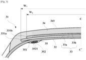
- FIG. 3 is a schematic cross sectional view of a portion of the tire 31 according to the third embodiment of the present invention.
- the constitution of the third embodiment is similar to that of the first and the second embodiments other than the arrangement shown in Fig. 3 , thus description will be made referring to Fig. 3 .
- 2 belt layers 33 being placed radially outward of the at least one carcass layer 32, a first belt layer 33a and a second belt layer 33b, the second belt layer 33b is positioned radially outwardly next to a radially innermost belt layer, the first belt layer 33a, and a tread 34 having a contact face 341 intended to come into contact with ground during rolling and being placed radially outward of the 2 belt layers 33.
- the first belt layer 33a and the second belt layer 33b have a different axial width, W 1 between two belt layer extremities 331a and W 2 between two belt layer extremities 331b respectively, and axial width W 2 of the second belt layer 33b is narrower than axial width W 1 of the first belt layer 33a.
- the tire 31 is provided also with at least one mass-damper 35 being composed of a soft part 351 which acts as a spring element of the mass-damper 35 and a hard part 352 which acts as a mass element of the mass-damper 35, being placed radially inward of the at least one carcass layer 32.
- the hard part 352 of the at least one mass-damper 35 has at least two level faces 3521 facing to generally radial orientation of the tire, all the at least two level faces 3521 of the hard part 352 of the mass-damper 35 contact with the soft part 351 of the mass-damper 35, as to surrounding completely the hard part 352 of the mass-damper 35 via the soft part 351, and the hard part 352 of the mass-damper 35 has no direct contact with the carcass layer 32 or the inner liner when exists.
- the at least one mass-damper 35 is attached to the tire 31 as to an axial center of the hard part 352 of the at least one mass-damper 35 locates in a region axially from a position axially 10% of the width W(W 2 ) of the second belt layer 33b inwardly from the belt layer extremity 331b of the second belt layer 33b to a position axially 10% of the width W(W 2 ) of the second belt layer 331b outwardly from the belt layer extremity 331b of the second belt layer 33b or to axially inward of the belt layer extremity of the widest belt layer in the at least two belt layers 33 whichever is axially inward.
- the widest belt layer is the first belt layer 33a.
- the Example was a tire as described in the above second embodiment.
- the Reference was a tire having the same construction as Example but without mass-damper. All the Example and Reference were made of the same rubber-based material, typical rubber-based material used for passenger car tire.
- Example and Reference were both 205/55R16, mounted onto a rim of 6.5J ⁇ 16, and inflated to 180 kPa.
- a sound pressure level of the unused test tires mounted onto abovementioned rim, inflated to abovementioned internal pressure were measured while applying a load of 452daN, running 90kph on a drum of 2.7m in diameter having ISO surface in a semi anechoic chamber, via a microphone installed axially 1m outward from a center of tire contact, radially 0.2m backward from a tire rolling axis and 0.32m in height.
- the result shows 0.3 dBA improvement in overall sound pressure level with the Example over the Reference, with more than 5 dBA improvement in sound pressure level in a range from 500 Hz to 700 Hz.
Landscapes
- Engineering & Computer Science (AREA)
- Mechanical Engineering (AREA)
- Tires In General (AREA)
Description
- The present invention relates to a tire, in particular to a tire possible to reduce vibrational noise.
- It is known that noise emitted by a tire when rolling originates, inter alia, from vibrations of its structure following contact of the tire with uneven roadway, also giving rise to a generation of various sound waves. This is all ultimately manifested in a form of noise, both inside and outside of a vehicle. Amplitude of these various manifestations is dependent on modes of vibration characteristic of the tire but also on nature of road surface on which the vehicle is moving. A range of frequencies corresponding to the noise generated by the tire typically extends from 20 to 4,000 Hz approximately.
-
WO2014/137675 discloses a tire comprising a plurality of vibration absorbers affecting structural resonances of a tire for reducing noise arising from structural vibration consisting of a spring element and a mass element. -
JP2006-256531 IT TO20110472 A1 EP 1577123 A1 . - Recently for a purpose of tire weight reduction while maintaining or even improving handling performance, a tire having improved tread stiffness is known. However with such the tire, noise due to tire's structural vibration appears in a frequency which have not been considered problematic, and it is difficult to absorb such tire's structural vibration with the above arrangements. Also with the above arrangements, there is a problem that the vibration absorbers or the dynamic damper (both can be considered as "mass-damper") need to be installed after the tire being cured using scotch tape, glue or alike onto an internal surface of the tire, thus low in productivity of such the tire provided with vibration absorbers / dynamic damper.
-
- PTL 1:
WO2014/137675 - PTL 2:
JP2006-256531 - Therefore, there is a need for a tire which makes it possible to attenuate a noise due to tire's structural vibration efficiently with improved productivity.
- A "radial direction/orientation" is a direction/orientation perpendicular to axis of rotation of the tire. This direction/orientation corresponds to thickness orientation of the tread.
- An "axial direction/orientation" is a direction/orientation parallel to axis of rotation of the tire.
- A "circumferential direction/orientation" is a direction/orientation which is tangential to any circle centered on axis of rotation. This direction/orientation is perpendicular to both the axial direction/orientation and the radial direction/orientation.
- A "tire" means all types of elastic tire whether or not subjected to an internal pressure.
- A "tread" of a tire means a quantity of rubber material bounded by lateral surfaces and by two main surfaces one of which is intended to come into contact with ground when the tire is rolling.
- Unless otherwise specified, a range represented as "between a and b" means greater than a and less than b (does not include the upper and lower limiting numbers), and a range represented as "from a to b" represents more than or equal to a and less than or equal to b (includes the upper and lower limiting numbers).
- It is thus an object of the invention to provide a tire provided with a mass-damper, such the tire can provide improvement on noise due to structural vibration with improved productivity.
- The present invention provides the tire as defined in appended
claim 1. Advantageous embodiments are provided as defined in the corresponding dependent claims. - The present application also discloses a tire comprising; at least one carcass layer; at least one belt layer having an axial width W between two belt layer extremities and being placed radially outward of the at least one carcass layer; a tread having a contact face intended to come into contact with ground during rolling and being placed radially outward of the at least one belt layer; at least one mass-damper being composed of a soft part and a hard part and being placed radially inward of the at least one carcass layer, the hard part of the at least one mass-damper having at least two level faces facing to generally radial orientation of the tire, the hard part of the at least one mass-damper contacting with the soft part of the at least one mass-damper on at least radially outward one of the at least two level faces, an axial center of the hard part of the at least one mass-damper locates in a region axially from the belt layer extremity to a position axially 1/3 of the width W inwardly from the belt layer extremity.
- This arrangement provides improvement of noise performance and productivity simultaneously.
- Since the at least one mass-damper is composed of a soft part and a hard part and is placed radially inward of the at least one carcass layer, the hard part of the at least one mass-damper has at least two level faces facing to generally radial orientation of the tire, the hard part of the at least one mass-damper contacts with the soft part of the at least one mass-damper on at least radially outward one of the at least two level faces, the mass-damper is suitable to absorb tire's structural vibration due to improved tread stiffness that has a vibration mode in shearing (generally tire axial) orientation, thus noise due to tire's structural vibration can be improved.
- Also at the same time, since an axial center of the hard part, axially middle between two axially extremities of the hard part, of the at least one mass-damper locates in a region axially from the belt layer extremity to a position axially 1/3 of the width W inwardly from the belt layer extremity, as such the vibration mode generates maximum displacement in shearing (generally tire axial) orientation in such the region, the mass-damper can further effectively absorb tire's structural vibration due to improved tread stiffness that has the vibration mode in shearing (generally tire axial) orientation, thus noise due to tire's structural vibration can further be improved.
- Since this location of the mass-damper, the axial center of the hard part of the at least one mass-damper locates in the region axially from the belt layer extremity to the position axially 1/3 of the width W inwardly from the belt layer extremity, is the location where a movement of a molding by membrane generates less geometrical change during molding, thus the mass-damper is possible to install onto a green tire before curing which is possible to eliminate an installation operation after curing, thus productivity of the tire provided with the mass-damper can be improved.
- According to another aspect of the disclosure, the tire has at least two belt layers comprising a second belt layer being positioned radially outwardly next to a radially innermost belt layer, and the axial center of the hard part of the at least one mass-damper locates in a region axially from a position axially 10% of the width W of the second belt layer inwardly from the belt layer extremity of the second belt layer to a position axially 10% of the width W of the second belt layer outwardly from the belt layer extremity of the second belt layer or to axially inward of the belt layer extremity of the widest belt layer in the at least two belt layers whichever is axially inward.
- According to this arrangement, it is possible to absorb tire's structural vibration due to improved tread stiffness, as the vibration mode generates maximum displacement in shearing (generally tire axial) orientation in particular in such the region, thus noise due to tire's structural vibration can further be improved.
- On the other words, if the axial center of the hard part of the at least one mass-damper locates out of the above region, there is a risk that absorption of tire's structural vibration due to improved tread stiffness would be insufficient thus noise due to tire's structural vibration cannot be improved.
- According to another aspect of the disclosure, a ratio between a Young modulus Ys of the soft part and a Young modulus Yh of the hard part of the mass-damper (Ys/Yh) is at most equal to 0.2.
- If this ratio of Young modulus is more than 0.2, there is a risk that the hard part is not possible to act as a mass element of the mass-damper, which leads insufficient absorption of tire's structural vibration due to improved tread stiffness thus noise due to tire's structural vibration cannot be improved. By setting this ratio at most equal to 0.2, the hard part can act as the mass element and the soft part can act as a spring element of the mass-damper correctly, thus noise due to tire's structural vibration can further be improved.
- This ratio of the Young modulus Ys of the soft part and the Young modulus Yh of the hard part of the mass-damper (Ys/Yh) is preferably at most equal to 0.18, more preferably at most equal to 0.15 and still more preferably at most equal to 0.12.
- According to another aspect of the disclosure, a ratio between a material density Dh of the hard part and a material density Ds of the soft part of the mass-damper (Dh/Ds) is at least equal to 1.7.
- If this ratio of material density is less than 1.7, there is a risk that the hard part is not possible to act as a mass element of the mass-damper, or the soft part is not possible to act as a spring element of the mass-damper, which leads insufficient absorption of tire's structural vibration due to improved tread stiffness thus noise due to tire's structural vibration cannot be improved. By setting this ratio at least equal to 1.7, the hard part can act as the mass element and the soft part can act as a spring element of the mass-damper correctly, thus noise due to tire's structural vibration can further be improved.
- This ratio of material density is preferably at least equal to 1.8, more preferably at least equal to 2.0.
- According to another aspect of the disclosure, all the at least two level faces of the hard part of the mass-damper contact with the soft part of the mass-damper.
- According to this arrangement, it is possible to ease handling of a green product during manufacturing of the tire as the soft part as to surrounding the hard part would prevent detachment of the hard part thus productivity of such the tire can further be improved.
- According to another aspect of the disclosure, the tire has two mass-dampers.
- According to this arrangement, it is possible to absorb tire's structural vibration due to improved tread stiffness more effectively and efficiently, thus noise due to tire's structural vibration can further be improved.
- According to another aspect of the disclosure, a resonance frequency of the mass-damper (5) is between 600 Hz and 700 Hz.
- According to this arrangement, it is possible to absorb tire's structural vibration due to improved tread stiffness more effectively and efficiently, as such a tire's structural vibration frequency appears around 650 Hz, thus noise due to tire's structural vibration can further be improved.
- According to the arrangements described above, it is possible to provide a tire with a mass-damper, such the tire can provide improvement on noise due to structural vibration with improved productivity of such the tire.
- Other characteristics and advantages of the invention arise from the description made hereafter in reference to the annexed drawings which show, as nonrestrictive examples, the embodiment of the invention.
- In these drawings:
- [
fig.1]Fig. 1 is a schematic cross sectional view of a portion of a tire according to a first embodiment of the present invention; - [
fig.2]Fig. 2 is a schematic cross sectional view of a portion of a tire according to a second embodiment of the present invention; - [
fig.3]Fig. 3 is a schematic cross sectional view of a portion of a tire according to a third embodiment of the present invention; - Preferred embodiments of the present invention will be described below referring to the drawings.
- A
tire 1 according to a first embodiment of the present invention will be described referring toFig. 1 . -
Fig. 1 is a schematic cross sectional view of a portion of a tire according to a first embodiment of the present invention. Thetire 1 shown in thisfigure 1 is a half of so-called summit portion divided with respect to a center line C-C'. - The
tire 1 is a tire having dimension 205/55R16 provided with at least onecarcass layer 2, a main body of the tire which may or may not be provided with an inner liner for inhibiting loss of air pressure, and at least onebelt layer 3 being placed radially outward of the at least onecarcass layer 2, a rubber-coated layer of metallic or textile or other material in a form of cable or wire or strings having an axial width W between twobelt layer extremities 31, an axially outer most of thebelt layer 3, and a tread 4 having acontact face 41 intended to come into contact with ground during rolling and being placed radially outward of the at least onebelt layer 3. - As shown in
Fig. 1 , thetire 1 is provided also with at least one mass-damper 5 being composed of asoft part 51 which acts as a spring element of the mass-damper 5 and ahard part 52 which acts as a mass element of the mass-damper 5, being placed radially inward of the at least onecarcass layer 2. - As shown in
Fig. 1 , thehard part 52 of the at least one mass-damper 5 has at least two level faces 521 facing to generally radial orientation of the tire and twoupright faces 522 facing to generally axial orientation of the tire, thehard part 52 of the at least one mass-damper 5 contacting with thesoft part 51 of the at least one mass-damper 5 on radially outward one of the at least twolevel face 521 and on twoupright faces 522, as to surround radially outward portion of thehard part 52 by thesoft part 51 so that thehard part 52 of the mass-damper 5 has no direct contact with thecarcass layer 2 or the inner liner when exists. - As shown in
Fig. 1 , the at least one mass-damper 5 is attached to thetire 1 as to an axial center of thehard part 52 of the at least one mass-damper 5 locates in a region axially between thebelt layer extremity 31 and a position axially 1/3 of the width W inwardly from thebelt layer extremity 31, which denotes as W' in thisfigure 1 . - A ratio between a Young modulus Ys of the
soft part 51 and a Young modulus Yh of thehard part 52 of the mass-damper 5 (Ys/Yh) is at most equal to 0.2. In this embodiment the Young modulus Ys of thesoft part 51 is 0.2 MPa and the Young modulus Yh of thehard part 52 is 2.0 MPa, thus the ratio between the Young modulus Ys of thesoft part 51 and the Young modulus Yh of the hard part 52 (Ys/Yh) is 0.1. - This ratio of the Young modulus Ys of the
soft part 51 and the Young modulus Yh of thehard part 52 of the mass-damper (Ys/Yh) is preferably at most equal to 0.18, more preferably at most equal to 0.15 and still more preferably at most equal to 0.12. - A ratio between a material density Dh of the
hard part 52 and a material density Ds of thesoft part 51 of the mass-damper 5 (Dh/Ds) is at least equal to 1.7. In this embodiment the material density Dh of thehard part 52 is 2.5 g/cm3 and the material density Ds of thesoft part 51 is 0.9 g/cm3, thus the ratio between the material density Dh of thehard part 52 and the material density Ds of thesoft part 51 of the mass-damper 5 (Dh/Ds) is 2.78. - This ratio between the material density Dh of the
hard part 52 and the material density Ds of thesoft part 51 of the mass-damper 5 (Dh/Ds) is preferably at least equal to 1.8, more preferably at least equal to 2.0. - Since the at least one mass-
damper 5 is composed of asoft part 51 and ahard part 52 and is placed radially inward of the at least onecarcass layer 2, thehard part 51 of the at least one mass-damper 5 has at least two level faces 521 facing to generally radial orientation of the tire, thehard part 52 of the at least one mass-damper 5 contacts with thesoft part 51 of the at least one mass-damper 5 on at least radially outward one of the at least two level faces 521, the mass-damper 5 is suitable to absorb tire's structural vibration due to improved tread stiffness that has a vibration mode in shearing (generally tire axial) orientation, thus noise due to tire's structural vibration can be improved. - Also at the same time, since an axial center of the
hard part 52 of the at least one mass-damper 5 locates in a region axially from thebelt layer extremity 31 to a position axially 1/3 of the width W inwardly from thebelt layer extremity 31, as such the vibration mode generates maximum displacement in shearing (generally tire axial) orientation in such the region, the mass-damper 5 can further effectively absorb tire's structural vibration due to improved tread stiffness that has the vibration mode in shearing (generally tire axial) orientation, thus noise due to tire's structural vibration can further be improved. - Since this location of the mass-
damper 5, the axial center of thehard part 52 of the at least one mass-damper 5 locates in the region axially from thebelt layer extremity 31 to the position axially 1/3 of the width W inwardly from thebelt layer extremity 31, is the location where a movement of a molding by membrane generates less geometrical change during molding, thus the mass-damper 5 is possible to install onto a green tire before curing which is possible to eliminate an installation operation after curing, thus productivity of the tire provided with the mass-damper can be improved. - Since the ratio between the Young modulus Ys of the
soft part 51 and the Young modulus Yh of thehard part 52 of the mass-damper 5 (Ys/Yh) is at most equal to 0.2, thehard part 52 can act as the mass element and thesoft part 51 can act as a spring element of the mass-damper 5 correctly, thus noise due to tire's structural vibration can further be improved. - If this ratio of Young modulus is more than 0.2, there is a risk that the
hard part 52 is not possible to act as a mass element of the mass-damper 5, which leads insufficient absorption of tire's structural vibration due to improved tread stiffness thus noise due to tire's structural vibration cannot be improved. - Since the ratio between the material density Dh of the
hard part 52 and the material density Ds of thesoft part 51 of the mass-damper 5 (Dh/Ds) is at least equal to 1.7, thehard part 52 can act as the mass element and thesoft part 51 can act as a spring element of the mass-damper 5 correctly, thus noise due to tire's structural vibration can further be improved. - If this ratio of material density is less than 1.7, there is a risk that the
hard part 52 is not possible to act as a mass element of the mass-damper 5, or thesoft part 51 is not possible to act as a spring element of the mass-damper 5, which leads insufficient absorption of tire's structural vibration due to improved tread stiffness thus noise due to tire's structural vibration cannot be improved. - A resonance frequency of the mass-
damper 5 is between 600 Hz and 700 Hz. In this embodiment the resonance frequency of the mass-damper 5 is set at 650 Hz for absorbing tire's structural vibration due to improved tread stiffness more effectively and efficiently, as such a tire's structural vibration frequency appears around 650 Hz. - The tire may have two mass-
dampers 5 for more effective and efficient absorption of tire's structural vibration due to improved tread stiffness, symmetrically or asymmetrically with respect to the center line C-C'. - The mass-
damper 5 may be provided continuously in circumferential orientation, may be provided discontinuously in circumferential orientation, or may be provided circumferentially continuoussoft part 51 with circumferentially discontinuoushard part 52. The mass-damper 5 may be extending circumferentially in straight, waved or zigzagged manner. - The mass-
damper 5 may be attached to thecarcass layer 2, or to the inner liner if exists, or may be installed between thecarcass layer 2 and the inner liner. - A
tire 21 according to a second embodiment of the present invention will be described referring toFig. 2. Fig. 2 is a schematic cross sectional view of a portion of thetire 21 according to the second embodiment of the present invention. The constitution of the second embodiment is similar to that of the first embodiment other than the arrangement shown inFig. 2 , thus description will be made referring toFig. 2 . - In the second embodiment, 2 belt layers 23 being placed radially outward of the at least one
carcass layer 22, afirst belt layer 23a and asecond belt layer 23b, thesecond belt layer 23b is positioned radially outwardly next to a radially innermost belt layer, thefirst belt layer 23a, and atread 24 having acontact face 241 intended to come into contact with ground during rolling and being placed radially outward of the 2 belt layers 23. Thefirst belt layer 23a and thesecond belt layer 23b have a different axial width, W1 between twobelt layer extremities 231a and W2 between twobelt layer extremities 231b respectively, and axial width W2 of thesecond belt layer 23b is narrower than axial width W1 of thefirst belt layer 23a. - As shown in
Fig. 2 , thetire 21 is provided also with at least one mass-damper 25 being composed of asoft part 251 which acts as a spring element of the mass-damper 25 and ahard part 252 which acts as a mass element of the mass-damper 25, being placed radially inward of the at least onecarcass layer 22. - As shown in
Fig. 2 , thehard part 252 of the at least one mass-damper 25 has at least two level faces 2521 facing to generally radial orientation of the tire and twoupright faces 2522 facing to generally axial orientation of the tire, thehard part 252 of the at least one mass-damper 25 contacting with thesoft part 251 of the at least one mass-damper 25 on radially outward one of the at least twolevel face 2521 and on axially outward one of the twoupright faces 2522, and thehard part 252 of the mass-damper 25 has no direct contact with thecarcass layer 22 or the inner liner when exists. - As shown in
Fig. 2 , the at least one mass-damper 25 is attached to thetire 21 as to an axial center of thehard part 252 of the at least one mass-damper 25 locates in a region axially from a position axially 10% of the width W(W2) of thesecond belt layer 23b inwardly from thebelt layer extremity 231b of thesecond belt layer 23b to a position axially 10% of the width W(W2) of thesecond belt layer 231b outwardly from thebelt layer extremity 231b of thesecond belt layer 23b or to axially inward of the belt layer extremity of the widest belt layer in the at least twobelt layers 23 whichever is axially inward. In this embodiment the widest belt layer is thefirst belt layer 23a. - Since the
tire 21 has at least twobelt layers 23 comprising thesecond belt layer 23b being positioned radially outwardly next to a radially innermost belt layer (thefirst belt layer 23a) and the at least one mass-damper 25 is attached to thetire 21 as to an axial center of thehard part 252 of the at least one mass-damper 25 locates in a region axially from a position axially 10% of the width W(W2) of thesecond belt layer 23b inwardly from thebelt layer extremity 231b of thesecond belt layer 23b to a position axially 10% of the width W(W2) of thesecond belt layer 231b outwardly from thebelt layer extremity 231b of thesecond belt layer 23b or to axially inward of the belt layer extremity of the widest belt layer in the at least twobelt layers 23 whichever is axially inward. In this embodiment the widest belt layer is thefirst belt layer 23a, it is possible to absorb tire's structural vibration due to improved tread stiffness, as the vibration mode generates maximum displacement in shearing (generally tire axial) orientation in particular in such the region, thus noise due to tire's structural vibration can further be improved. - As the
hard part 252 of the at least one mass-damper 25 contacting with thesoft part 251 of the at least one mass-damper 5 on radially outward one of the at least twolevel face 2521 and on axially outward one of the twoupright faces 522, it is possible to minimize an impact on mass increase due to installation of the mass-damper 25 while keeping improved noise performance and productivity of thetire 21. - A
tire 31 according to a third embodiment of the present invention will be described referring toFig. 3. Fig. 3 is a schematic cross sectional view of a portion of thetire 31 according to the third embodiment of the present invention. The constitution of the third embodiment is similar to that of the first and the second embodiments other than the arrangement shown inFig. 3 , thus description will be made referring toFig. 3 . - In the third embodiment, 2 belt layers 33 being placed radially outward of the at least one
carcass layer 32, afirst belt layer 33a and asecond belt layer 33b, thesecond belt layer 33b is positioned radially outwardly next to a radially innermost belt layer, thefirst belt layer 33a, and atread 34 having acontact face 341 intended to come into contact with ground during rolling and being placed radially outward of the 2 belt layers 33. Thefirst belt layer 33a and thesecond belt layer 33b have a different axial width, W1 between twobelt layer extremities 331a and W2 between twobelt layer extremities 331b respectively, and axial width W2 of thesecond belt layer 33b is narrower than axial width W1 of thefirst belt layer 33a. - As shown in
Fig. 3 , thetire 31 is provided also with at least one mass-damper 35 being composed of asoft part 351 which acts as a spring element of the mass-damper 35 and ahard part 352 which acts as a mass element of the mass-damper 35, being placed radially inward of the at least onecarcass layer 32. - As shown in
Fig. 3 , thehard part 352 of the at least one mass-damper 35 has at least two level faces 3521 facing to generally radial orientation of the tire, all the at least two level faces 3521 of thehard part 352 of the mass-damper 35 contact with thesoft part 351 of the mass-damper 35, as to surrounding completely thehard part 352 of the mass-damper 35 via thesoft part 351, and thehard part 352 of the mass-damper 35 has no direct contact with thecarcass layer 32 or the inner liner when exists. - As shown in
Fig. 3 , the at least one mass-damper 35 is attached to thetire 31 as to an axial center of thehard part 352 of the at least one mass-damper 35 locates in a region axially from a position axially 10% of the width W(W2) of thesecond belt layer 33b inwardly from thebelt layer extremity 331b of thesecond belt layer 33b to a position axially 10% of the width W(W2) of thesecond belt layer 331b outwardly from thebelt layer extremity 331b of thesecond belt layer 33b or to axially inward of the belt layer extremity of the widest belt layer in the at least twobelt layers 33 whichever is axially inward. In this embodiment the widest belt layer is thefirst belt layer 33a. - Since all the at least two level faces 3521 of the
hard part 352 of the mass-damper 35 contact with thesoft part 351 of the mass-damper 35, it is possible to ease handling of a green product during manufacturing of thetire 31 as thesoft part 351 as to surrounding thehard part 352 would prevent detachment of thehard part 352 thus productivity of such thetire 31 can further be improved. - In order to confirm the effect of the present invention, one type of a tire of Example to which the present invention is applied and another type of tire of Reference were prepared.
- The Example was a tire as described in the above second embodiment. The Reference was a tire having the same construction as Example but without mass-damper. All the Example and Reference were made of the same rubber-based material, typical rubber-based material used for passenger car tire.
- The tire dimension of Example and Reference were both 205/55R16, mounted onto a rim of 6.5J×16, and inflated to 180 kPa.
- A sound pressure level of the unused test tires mounted onto abovementioned rim, inflated to abovementioned internal pressure were measured while applying a load of 452daN, running 90kph on a drum of 2.7m in diameter having ISO surface in a semi anechoic chamber, via a microphone installed axially 1m outward from a center of tire contact, radially 0.2m backward from a tire rolling axis and 0.32m in height.
- The result shows 0.3 dBA improvement in overall sound pressure level with the Example over the Reference, with more than 5 dBA improvement in sound pressure level in a range from 500 Hz to 700 Hz.
- The invention is not limited to the examples described and represented and only defined by the appended claims.
-
- 1, 21, 31 tire
- 2, 22, 32 carcass layer
- 3, 23, 33 belt layer
- 31, 231, 331 belt layer extremity
- 4, 24, 34 tread
- 41, 241, 341 contact face
- 5, 25, 35 mass-damper
- 51, 251, 351 soft part of mass-damper
- 52, 252, 352 hard part of mass-damper
- 521, 2521, 3521 level face of hard part
- 522, 2522 upright face of hard part
Claims (7)
- A tire (1) comprising; at least one carcass layer (2); at least one belt layer (3) having an axial width (W) between two belt layer extremities (31) and being placed radially outward of the at least one carcass layer (2); a tread (4) having a contact face (41) intended to come into contact with ground during rolling and being placed radially outward of the at least one belt layer (3); at least one mass-damper (5) being composed of a soft part (51) and a hard part (52) and being placed radially inward of the at least one carcass layer (2),the hard part (52) of the at least one mass-damper (5) having at least two level faces (521) facing to generally radial orientation of the tire, the hard part (52) of the at least one mass-damper (5) contacting with the soft part (51) of the at least one mass-damper (5) on at least radially outward one of the at least two level faces (521), the hard part (52) of the at least one mass-damper (5) having two upright faces (522) connecting the two level faces (521) respectively and facing to generally axial orientation of the tire,wherein an axial center of the hard part (52) of the at least one mass-damper (5) is located in a region axially from the belt layer extremity (31) to a position axially 1/3 of the width (W) inwardly from the belt layer extremity (31),the tire (1) being characterized in thatthe soft part (51) acts as a spring element of the mass-damper (5) and the hard part (52) acts as a mass element of the mass-damper (5), and in thatthe hard part (52) of the at least one mass-damper (5) contacts with the soft part (51) of the at least one mass-damper (5) on at least one of the upright faces (522) of the hard part (52) facing axially outward so as to surround a radially outward portion of the hard part (52) by the soft part (51).
- The tire (1) according to claim 1, wherein the tire (1) has at least two belt layers (3) comprising a second belt layer being positioned radially outwardly next to a radially innermost belt layer, and wherein the axial center of the hard part (52) of the at least one mass-damper (5) is located in a region axially from a position axially 10% of the width (W) of the second belt layer inwardly from the belt layer extremity of the second belt layer to a position axially 10% of the width (W) of the second belt layer outwardly from the belt layer extremity of the second belt layer or to axially inward of the belt layer extremity (31) of the widest belt layer in the at least two belt layers (3) whichever is axially inward.
- The tire (1) according to claim 1 or claim 2, wherein a ratio between a Young modulus (Ys) of the soft part (51) and a Young modulus (Yh) of the hard part (52) of the mass-damper (5) (Ys/Yh) is at most equal to 0.2.
- The tire (1) according to any one of the claims 1 to 3, wherein a ratio between a material density (Dh) of the hard part (52) and a material density (Ds) of the soft part (51) of the mass-damper (5) (Dh/Ds) is at least equal to 1.7.
- The tire (1) according to any one of the claims 1 to 4, wherein all the at least two level faces (521) of the hard part (52) of the mass-damper (5) contact with the soft part (51) of the mass-damper (5).
- The tire (1) according to any one of the claims 1 to 5, wherein the tire (1) has two mass-dampers (5).
- The tire (1) according to any one of the claims 1 to 6, wherein a resonance frequency of the mass-damper (5) is between 600 Hz and 700 Hz.
Applications Claiming Priority (1)
| Application Number | Priority Date | Filing Date | Title |
|---|---|---|---|
| PCT/JP2017/035166 WO2019064408A1 (en) | 2017-09-28 | 2017-09-28 | A tire comprising vibration absoeber |
Publications (3)
| Publication Number | Publication Date |
|---|---|
| EP3687835A1 EP3687835A1 (en) | 2020-08-05 |
| EP3687835A4 EP3687835A4 (en) | 2021-04-14 |
| EP3687835B1 true EP3687835B1 (en) | 2024-05-15 |
Family
ID=65902792
Family Applications (1)
| Application Number | Title | Priority Date | Filing Date |
|---|---|---|---|
| EP17926874.3A Active EP3687835B1 (en) | 2017-09-28 | 2017-09-28 | A tire comprising a vibration absorber |
Country Status (3)
| Country | Link |
|---|---|
| EP (1) | EP3687835B1 (en) |
| CN (1) | CN111194270B (en) |
| WO (1) | WO2019064408A1 (en) |
Family Cites Families (10)
| Publication number | Priority date | Publication date | Assignee | Title |
|---|---|---|---|---|
| EP1577123B1 (en) | 2004-03-16 | 2007-10-17 | Sumitomo Rubber Industries Ltd. | Pneumatic tire with noise damper |
| JP2006256531A (en) * | 2005-03-18 | 2006-09-28 | Nissan Motor Co Ltd | Hollow tire |
| JP2010149600A (en) * | 2008-12-24 | 2010-07-08 | Sumitomo Rubber Ind Ltd | Pneumatic tire with sound suppressor |
| JP4992937B2 (en) * | 2009-05-25 | 2012-08-08 | 横浜ゴム株式会社 | Pneumatic tire |
| JP5376657B2 (en) * | 2009-07-27 | 2013-12-25 | 株式会社ブリヂストン | Pneumatic tire |
| ITTO20110472A1 (en) * | 2011-05-30 | 2012-12-01 | Bridgestone Corp | LOW NOISE TIRE |
| JP2013112062A (en) * | 2011-11-25 | 2013-06-10 | Sumitomo Rubber Ind Ltd | Pneumatic tire with noise damper |
| US20140246133A1 (en) | 2013-03-04 | 2014-09-04 | E I Du Pont De Nemours And Company | Tire containing a component for reducing vibration-generated noise in a tire and method for reducing tire noise |
| JP6318515B2 (en) * | 2013-09-24 | 2018-05-09 | 横浜ゴム株式会社 | Pneumatic tire and manufacturing method thereof |
| DE112014006246B4 (en) * | 2014-01-23 | 2025-01-23 | The Yokohama Rubber Co., Ltd. | pneumatic tires |
-
2017
- 2017-09-28 CN CN201780095368.2A patent/CN111194270B/en active Active
- 2017-09-28 EP EP17926874.3A patent/EP3687835B1/en active Active
- 2017-09-28 WO PCT/JP2017/035166 patent/WO2019064408A1/en not_active Ceased
Also Published As
| Publication number | Publication date |
|---|---|
| WO2019064408A1 (en) | 2019-04-04 |
| EP3687835A4 (en) | 2021-04-14 |
| CN111194270B (en) | 2022-02-01 |
| EP3687835A1 (en) | 2020-08-05 |
| CN111194270A (en) | 2020-05-22 |
Similar Documents
| Publication | Publication Date | Title |
|---|---|---|
| US7213624B2 (en) | Noise damper and pneumatic tire with compensation tread groove | |
| JP4427007B2 (en) | Pneumatic tire | |
| US8365782B2 (en) | Tire noise reduction device and pneumatic tire | |
| EP3501858B1 (en) | Pneumatic tyre and pneumatic tyre and rim assembly | |
| US11453253B2 (en) | Pneumatic tire | |
| EP3722113B1 (en) | Pneumatic tire comprising resonance noise reduction structure | |
| US6588469B2 (en) | Tire noise reducing system | |
| JP4533130B2 (en) | Pneumatic tire and rim assembly | |
| CN108349306B (en) | Pneumatic tire | |
| CN100475559C (en) | Tire cavity resonance suppression device and pneumatic tire | |
| JP6674773B2 (en) | Sound absorbing member and pneumatic tire | |
| US20200338935A1 (en) | Pneumatic Tire | |
| CN109476181B (en) | Pneumatic tires | |
| CN110944854A (en) | tire | |
| KR101722715B1 (en) | Non-pneumatic tire | |
| EP3687835B1 (en) | A tire comprising a vibration absorber | |
| CN111372792B (en) | Pneumatic tires | |
| KR102080393B1 (en) | A pneumatic tire | |
| CN108602385B (en) | Pneumatic tires | |
| US20210188020A1 (en) | Pneumatic Tire | |
| WO2016002089A1 (en) | A tire improved in noise | |
| KR100792010B1 (en) | Pneumatic tire which reduced resonance sound | |
| CN117621716A (en) | Tire-rim assembly | |
| JP2011168252A (en) | Pneumatic tire and method of manufacturing the same | |
| CN113825654A (en) | Pneumatic tires |
Legal Events
| Date | Code | Title | Description |
|---|---|---|---|
| STAA | Information on the status of an ep patent application or granted ep patent |
Free format text: STATUS: THE INTERNATIONAL PUBLICATION HAS BEEN MADE |
|
| PUAI | Public reference made under article 153(3) epc to a published international application that has entered the european phase |
Free format text: ORIGINAL CODE: 0009012 |
|
| STAA | Information on the status of an ep patent application or granted ep patent |
Free format text: STATUS: REQUEST FOR EXAMINATION WAS MADE |
|
| 17P | Request for examination filed |
Effective date: 20200327 |
|
| AK | Designated contracting states |
Kind code of ref document: A1 Designated state(s): AL AT BE BG CH CY CZ DE DK EE ES FI FR GB GR HR HU IE IS IT LI LT LU LV MC MK MT NL NO PL PT RO RS SE SI SK SM TR |
|
| AX | Request for extension of the european patent |
Extension state: BA ME |
|
| DAV | Request for validation of the european patent (deleted) | ||
| DAX | Request for extension of the european patent (deleted) | ||
| A4 | Supplementary search report drawn up and despatched |
Effective date: 20210312 |
|
| RIC1 | Information provided on ipc code assigned before grant |
Ipc: B60C 5/00 20060101AFI20210308BHEP |
|
| STAA | Information on the status of an ep patent application or granted ep patent |
Free format text: STATUS: EXAMINATION IS IN PROGRESS |
|
| 17Q | First examination report despatched |
Effective date: 20220905 |
|
| REG | Reference to a national code |
Ref country code: DE Ref legal event code: R079 Free format text: PREVIOUS MAIN CLASS: B60C0005000000 Ipc: B60C0019000000 Ref country code: DE Ref legal event code: R079 Ref document number: 602017082020 Country of ref document: DE Free format text: PREVIOUS MAIN CLASS: B60C0005000000 Ipc: B60C0019000000 |
|
| RIC1 | Information provided on ipc code assigned before grant |
Ipc: B60C 5/00 20060101ALI20231218BHEP Ipc: B60C 19/00 20060101AFI20231218BHEP |
|
| GRAP | Despatch of communication of intention to grant a patent |
Free format text: ORIGINAL CODE: EPIDOSNIGR1 |
|
| STAA | Information on the status of an ep patent application or granted ep patent |
Free format text: STATUS: GRANT OF PATENT IS INTENDED |
|
| INTG | Intention to grant announced |
Effective date: 20240216 |
|
| GRAS | Grant fee paid |
Free format text: ORIGINAL CODE: EPIDOSNIGR3 |
|
| GRAA | (expected) grant |
Free format text: ORIGINAL CODE: 0009210 |
|
| STAA | Information on the status of an ep patent application or granted ep patent |
Free format text: STATUS: THE PATENT HAS BEEN GRANTED |
|
| AK | Designated contracting states |
Kind code of ref document: B1 Designated state(s): AL AT BE BG CH CY CZ DE DK EE ES FI FR GB GR HR HU IE IS IT LI LT LU LV MC MK MT NL NO PL PT RO RS SE SI SK SM TR |
|
| REG | Reference to a national code |
Ref country code: CH Ref legal event code: EP Ref country code: GB Ref legal event code: FG4D |
|
| REG | Reference to a national code |
Ref country code: IE Ref legal event code: FG4D |
|
| REG | Reference to a national code |
Ref country code: DE Ref legal event code: R096 Ref document number: 602017082020 Country of ref document: DE |
|
| REG | Reference to a national code |
Ref country code: LT Ref legal event code: MG9D |
|
| REG | Reference to a national code |
Ref country code: NL Ref legal event code: MP Effective date: 20240515 |
|
| PG25 | Lapsed in a contracting state [announced via postgrant information from national office to epo] |
Ref country code: IS Free format text: LAPSE BECAUSE OF FAILURE TO SUBMIT A TRANSLATION OF THE DESCRIPTION OR TO PAY THE FEE WITHIN THE PRESCRIBED TIME-LIMIT Effective date: 20240915 |
|
| PG25 | Lapsed in a contracting state [announced via postgrant information from national office to epo] |
Ref country code: BG Free format text: LAPSE BECAUSE OF FAILURE TO SUBMIT A TRANSLATION OF THE DESCRIPTION OR TO PAY THE FEE WITHIN THE PRESCRIBED TIME-LIMIT Effective date: 20240515 |
|
| PG25 | Lapsed in a contracting state [announced via postgrant information from national office to epo] |
Ref country code: FI Free format text: LAPSE BECAUSE OF FAILURE TO SUBMIT A TRANSLATION OF THE DESCRIPTION OR TO PAY THE FEE WITHIN THE PRESCRIBED TIME-LIMIT Effective date: 20240515 Ref country code: HR Free format text: LAPSE BECAUSE OF FAILURE TO SUBMIT A TRANSLATION OF THE DESCRIPTION OR TO PAY THE FEE WITHIN THE PRESCRIBED TIME-LIMIT Effective date: 20240515 |
|
| PG25 | Lapsed in a contracting state [announced via postgrant information from national office to epo] |
Ref country code: GR Free format text: LAPSE BECAUSE OF FAILURE TO SUBMIT A TRANSLATION OF THE DESCRIPTION OR TO PAY THE FEE WITHIN THE PRESCRIBED TIME-LIMIT Effective date: 20240816 |
|
| PG25 | Lapsed in a contracting state [announced via postgrant information from national office to epo] |
Ref country code: PT Free format text: LAPSE BECAUSE OF FAILURE TO SUBMIT A TRANSLATION OF THE DESCRIPTION OR TO PAY THE FEE WITHIN THE PRESCRIBED TIME-LIMIT Effective date: 20240916 |
|
| REG | Reference to a national code |
Ref country code: AT Ref legal event code: MK05 Ref document number: 1686668 Country of ref document: AT Kind code of ref document: T Effective date: 20240515 |
|
| PG25 | Lapsed in a contracting state [announced via postgrant information from national office to epo] |
Ref country code: NL Free format text: LAPSE BECAUSE OF FAILURE TO SUBMIT A TRANSLATION OF THE DESCRIPTION OR TO PAY THE FEE WITHIN THE PRESCRIBED TIME-LIMIT Effective date: 20240515 |
|
| PG25 | Lapsed in a contracting state [announced via postgrant information from national office to epo] |
Ref country code: ES Free format text: LAPSE BECAUSE OF FAILURE TO SUBMIT A TRANSLATION OF THE DESCRIPTION OR TO PAY THE FEE WITHIN THE PRESCRIBED TIME-LIMIT Effective date: 20240515 |
|
| PG25 | Lapsed in a contracting state [announced via postgrant information from national office to epo] |
Ref country code: AT Free format text: LAPSE BECAUSE OF FAILURE TO SUBMIT A TRANSLATION OF THE DESCRIPTION OR TO PAY THE FEE WITHIN THE PRESCRIBED TIME-LIMIT Effective date: 20240515 |
|
| PG25 | Lapsed in a contracting state [announced via postgrant information from national office to epo] |
Ref country code: PL Free format text: LAPSE BECAUSE OF FAILURE TO SUBMIT A TRANSLATION OF THE DESCRIPTION OR TO PAY THE FEE WITHIN THE PRESCRIBED TIME-LIMIT Effective date: 20240515 |
|
| PG25 | Lapsed in a contracting state [announced via postgrant information from national office to epo] |
Ref country code: LV Free format text: LAPSE BECAUSE OF FAILURE TO SUBMIT A TRANSLATION OF THE DESCRIPTION OR TO PAY THE FEE WITHIN THE PRESCRIBED TIME-LIMIT Effective date: 20240515 |
|
| PG25 | Lapsed in a contracting state [announced via postgrant information from national office to epo] |
Ref country code: PT Free format text: LAPSE BECAUSE OF FAILURE TO SUBMIT A TRANSLATION OF THE DESCRIPTION OR TO PAY THE FEE WITHIN THE PRESCRIBED TIME-LIMIT Effective date: 20240916 Ref country code: PL Free format text: LAPSE BECAUSE OF FAILURE TO SUBMIT A TRANSLATION OF THE DESCRIPTION OR TO PAY THE FEE WITHIN THE PRESCRIBED TIME-LIMIT Effective date: 20240515 Ref country code: NO Free format text: LAPSE BECAUSE OF FAILURE TO SUBMIT A TRANSLATION OF THE DESCRIPTION OR TO PAY THE FEE WITHIN THE PRESCRIBED TIME-LIMIT Effective date: 20240815 Ref country code: NL Free format text: LAPSE BECAUSE OF FAILURE TO SUBMIT A TRANSLATION OF THE DESCRIPTION OR TO PAY THE FEE WITHIN THE PRESCRIBED TIME-LIMIT Effective date: 20240515 Ref country code: LV Free format text: LAPSE BECAUSE OF FAILURE TO SUBMIT A TRANSLATION OF THE DESCRIPTION OR TO PAY THE FEE WITHIN THE PRESCRIBED TIME-LIMIT Effective date: 20240515 Ref country code: IS Free format text: LAPSE BECAUSE OF FAILURE TO SUBMIT A TRANSLATION OF THE DESCRIPTION OR TO PAY THE FEE WITHIN THE PRESCRIBED TIME-LIMIT Effective date: 20240915 Ref country code: HR Free format text: LAPSE BECAUSE OF FAILURE TO SUBMIT A TRANSLATION OF THE DESCRIPTION OR TO PAY THE FEE WITHIN THE PRESCRIBED TIME-LIMIT Effective date: 20240515 Ref country code: GR Free format text: LAPSE BECAUSE OF FAILURE TO SUBMIT A TRANSLATION OF THE DESCRIPTION OR TO PAY THE FEE WITHIN THE PRESCRIBED TIME-LIMIT Effective date: 20240816 Ref country code: FI Free format text: LAPSE BECAUSE OF FAILURE TO SUBMIT A TRANSLATION OF THE DESCRIPTION OR TO PAY THE FEE WITHIN THE PRESCRIBED TIME-LIMIT Effective date: 20240515 Ref country code: ES Free format text: LAPSE BECAUSE OF FAILURE TO SUBMIT A TRANSLATION OF THE DESCRIPTION OR TO PAY THE FEE WITHIN THE PRESCRIBED TIME-LIMIT Effective date: 20240515 Ref country code: BG Free format text: LAPSE BECAUSE OF FAILURE TO SUBMIT A TRANSLATION OF THE DESCRIPTION OR TO PAY THE FEE WITHIN THE PRESCRIBED TIME-LIMIT Effective date: 20240515 Ref country code: AT Free format text: LAPSE BECAUSE OF FAILURE TO SUBMIT A TRANSLATION OF THE DESCRIPTION OR TO PAY THE FEE WITHIN THE PRESCRIBED TIME-LIMIT Effective date: 20240515 Ref country code: RS Free format text: LAPSE BECAUSE OF FAILURE TO SUBMIT A TRANSLATION OF THE DESCRIPTION OR TO PAY THE FEE WITHIN THE PRESCRIBED TIME-LIMIT Effective date: 20240815 |
|
| PG25 | Lapsed in a contracting state [announced via postgrant information from national office to epo] |
Ref country code: DK Free format text: LAPSE BECAUSE OF FAILURE TO SUBMIT A TRANSLATION OF THE DESCRIPTION OR TO PAY THE FEE WITHIN THE PRESCRIBED TIME-LIMIT Effective date: 20240515 |
|
| PG25 | Lapsed in a contracting state [announced via postgrant information from national office to epo] |
Ref country code: EE Free format text: LAPSE BECAUSE OF FAILURE TO SUBMIT A TRANSLATION OF THE DESCRIPTION OR TO PAY THE FEE WITHIN THE PRESCRIBED TIME-LIMIT Effective date: 20240515 |
|
| PG25 | Lapsed in a contracting state [announced via postgrant information from national office to epo] |
Ref country code: CZ Free format text: LAPSE BECAUSE OF FAILURE TO SUBMIT A TRANSLATION OF THE DESCRIPTION OR TO PAY THE FEE WITHIN THE PRESCRIBED TIME-LIMIT Effective date: 20240515 |
|
| PG25 | Lapsed in a contracting state [announced via postgrant information from national office to epo] |
Ref country code: SK Free format text: LAPSE BECAUSE OF FAILURE TO SUBMIT A TRANSLATION OF THE DESCRIPTION OR TO PAY THE FEE WITHIN THE PRESCRIBED TIME-LIMIT Effective date: 20240515 Ref country code: RO Free format text: LAPSE BECAUSE OF FAILURE TO SUBMIT A TRANSLATION OF THE DESCRIPTION OR TO PAY THE FEE WITHIN THE PRESCRIBED TIME-LIMIT Effective date: 20240515 |
|
| PG25 | Lapsed in a contracting state [announced via postgrant information from national office to epo] |
Ref country code: SM Free format text: LAPSE BECAUSE OF FAILURE TO SUBMIT A TRANSLATION OF THE DESCRIPTION OR TO PAY THE FEE WITHIN THE PRESCRIBED TIME-LIMIT Effective date: 20240515 |
|
| PG25 | Lapsed in a contracting state [announced via postgrant information from national office to epo] |
Ref country code: SM Free format text: LAPSE BECAUSE OF FAILURE TO SUBMIT A TRANSLATION OF THE DESCRIPTION OR TO PAY THE FEE WITHIN THE PRESCRIBED TIME-LIMIT Effective date: 20240515 Ref country code: SK Free format text: LAPSE BECAUSE OF FAILURE TO SUBMIT A TRANSLATION OF THE DESCRIPTION OR TO PAY THE FEE WITHIN THE PRESCRIBED TIME-LIMIT Effective date: 20240515 Ref country code: RO Free format text: LAPSE BECAUSE OF FAILURE TO SUBMIT A TRANSLATION OF THE DESCRIPTION OR TO PAY THE FEE WITHIN THE PRESCRIBED TIME-LIMIT Effective date: 20240515 Ref country code: EE Free format text: LAPSE BECAUSE OF FAILURE TO SUBMIT A TRANSLATION OF THE DESCRIPTION OR TO PAY THE FEE WITHIN THE PRESCRIBED TIME-LIMIT Effective date: 20240515 Ref country code: DK Free format text: LAPSE BECAUSE OF FAILURE TO SUBMIT A TRANSLATION OF THE DESCRIPTION OR TO PAY THE FEE WITHIN THE PRESCRIBED TIME-LIMIT Effective date: 20240515 Ref country code: CZ Free format text: LAPSE BECAUSE OF FAILURE TO SUBMIT A TRANSLATION OF THE DESCRIPTION OR TO PAY THE FEE WITHIN THE PRESCRIBED TIME-LIMIT Effective date: 20240515 |
|
| PG25 | Lapsed in a contracting state [announced via postgrant information from national office to epo] |
Ref country code: IT Free format text: LAPSE BECAUSE OF FAILURE TO SUBMIT A TRANSLATION OF THE DESCRIPTION OR TO PAY THE FEE WITHIN THE PRESCRIBED TIME-LIMIT Effective date: 20240515 |
|
| REG | Reference to a national code |
Ref country code: DE Ref legal event code: R097 Ref document number: 602017082020 Country of ref document: DE |
|
| PLBE | No opposition filed within time limit |
Free format text: ORIGINAL CODE: 0009261 |
|
| STAA | Information on the status of an ep patent application or granted ep patent |
Free format text: STATUS: NO OPPOSITION FILED WITHIN TIME LIMIT |
|
| 26N | No opposition filed |
Effective date: 20250218 |
|
| PG25 | Lapsed in a contracting state [announced via postgrant information from national office to epo] |
Ref country code: MC Free format text: LAPSE BECAUSE OF FAILURE TO SUBMIT A TRANSLATION OF THE DESCRIPTION OR TO PAY THE FEE WITHIN THE PRESCRIBED TIME-LIMIT Effective date: 20240515 Ref country code: SI Free format text: LAPSE BECAUSE OF FAILURE TO SUBMIT A TRANSLATION OF THE DESCRIPTION OR TO PAY THE FEE WITHIN THE PRESCRIBED TIME-LIMIT Effective date: 20240515 |
|
| REG | Reference to a national code |
Ref country code: CH Ref legal event code: PL |
|
| PG25 | Lapsed in a contracting state [announced via postgrant information from national office to epo] |
Ref country code: LU Free format text: LAPSE BECAUSE OF NON-PAYMENT OF DUE FEES Effective date: 20240928 |
|
| GBPC | Gb: european patent ceased through non-payment of renewal fee |
Effective date: 20240928 |
|
| PG25 | Lapsed in a contracting state [announced via postgrant information from national office to epo] |
Ref country code: GB Free format text: LAPSE BECAUSE OF NON-PAYMENT OF DUE FEES Effective date: 20240928 |
|
| REG | Reference to a national code |
Ref country code: BE Ref legal event code: MM Effective date: 20240930 |
|
| PG25 | Lapsed in a contracting state [announced via postgrant information from national office to epo] |
Ref country code: BE Free format text: LAPSE BECAUSE OF NON-PAYMENT OF DUE FEES Effective date: 20240930 |
|
| PG25 | Lapsed in a contracting state [announced via postgrant information from national office to epo] |
Ref country code: CH Free format text: LAPSE BECAUSE OF NON-PAYMENT OF DUE FEES Effective date: 20240930 |
|
| PG25 | Lapsed in a contracting state [announced via postgrant information from national office to epo] |
Ref country code: IE Free format text: LAPSE BECAUSE OF NON-PAYMENT OF DUE FEES Effective date: 20240928 |
|
| PG25 | Lapsed in a contracting state [announced via postgrant information from national office to epo] |
Ref country code: SE Free format text: LAPSE BECAUSE OF FAILURE TO SUBMIT A TRANSLATION OF THE DESCRIPTION OR TO PAY THE FEE WITHIN THE PRESCRIBED TIME-LIMIT Effective date: 20240515 |
|
| PGFP | Annual fee paid to national office [announced via postgrant information from national office to epo] |
Ref country code: DE Payment date: 20250919 Year of fee payment: 9 |
|
| PGFP | Annual fee paid to national office [announced via postgrant information from national office to epo] |
Ref country code: FR Payment date: 20250922 Year of fee payment: 9 |
|
| PG25 | Lapsed in a contracting state [announced via postgrant information from national office to epo] |
Ref country code: CY Free format text: LAPSE BECAUSE OF FAILURE TO SUBMIT A TRANSLATION OF THE DESCRIPTION OR TO PAY THE FEE WITHIN THE PRESCRIBED TIME-LIMIT; INVALID AB INITIO Effective date: 20170928 |
|
| PG25 | Lapsed in a contracting state [announced via postgrant information from national office to epo] |
Ref country code: HU Free format text: LAPSE BECAUSE OF FAILURE TO SUBMIT A TRANSLATION OF THE DESCRIPTION OR TO PAY THE FEE WITHIN THE PRESCRIBED TIME-LIMIT; INVALID AB INITIO Effective date: 20170928 |