EP3687833B1 - Vertically adjustable caster wheel - Google Patents
Vertically adjustable caster wheel Download PDFInfo
- Publication number
- EP3687833B1 EP3687833B1 EP18783342.1A EP18783342A EP3687833B1 EP 3687833 B1 EP3687833 B1 EP 3687833B1 EP 18783342 A EP18783342 A EP 18783342A EP 3687833 B1 EP3687833 B1 EP 3687833B1
- Authority
- EP
- European Patent Office
- Prior art keywords
- caster wheel
- wheel assembly
- alignment post
- upper housing
- bore
- Prior art date
- Legal status (The legal status is an assumption and is not a legal conclusion. Google has not performed a legal analysis and makes no representation as to the accuracy of the status listed.)
- Active
Links
Images



Classifications
-
- B—PERFORMING OPERATIONS; TRANSPORTING
- B60—VEHICLES IN GENERAL
- B60B—VEHICLE WHEELS; CASTORS; AXLES FOR WHEELS OR CASTORS; INCREASING WHEEL ADHESION
- B60B33/00—Castors in general ; Anti-clogging castors
- B60B33/04—Castors in general ; Anti-clogging castors adjustable, e.g. in height; linearly shifting castors
-
- B—PERFORMING OPERATIONS; TRANSPORTING
- B60—VEHICLES IN GENERAL
- B60B—VEHICLE WHEELS; CASTORS; AXLES FOR WHEELS OR CASTORS; INCREASING WHEEL ADHESION
- B60B33/00—Castors in general ; Anti-clogging castors
- B60B33/0036—Castors in general ; Anti-clogging castors characterised by type of wheels
- B60B33/0042—Double or twin wheels
-
- B—PERFORMING OPERATIONS; TRANSPORTING
- B60—VEHICLES IN GENERAL
- B60B—VEHICLE WHEELS; CASTORS; AXLES FOR WHEELS OR CASTORS; INCREASING WHEEL ADHESION
- B60B33/00—Castors in general ; Anti-clogging castors
- B60B33/02—Castors in general ; Anti-clogging castors with disengageable swivel action, i.e. comprising a swivel locking mechanism
- B60B33/025—Castors in general ; Anti-clogging castors with disengageable swivel action, i.e. comprising a swivel locking mechanism by using form-fit, e.g. front teeth
Definitions
- This disclosure relates to caster wheels, and more particularly to a caster wheel that is vertically adjustable from a top of the caster wheel.
- Heavy-duty caster wheels are frequently used to support relatively heavy loads transported by small forklift trucks, material handling carts, and the like.
- many designs require the caster wheel to be partially or entirely disassembled.
- Other caster wheel designs provide angular or height adjustment by accessing fasteners and/or springs from the bottom or sides of the caster wheel. In either instance, adjusting the height of the caster wheel may be a timely and inconvenient task. Therefore, a need exists for a quick and simple method for providing vertical adjustment of the caster wheel.
- FR2622151 discloses an accessory, which comprises an orientable wheel pivoting about a vertical axis, it further comprises, on the one hand, a body comprising a plate for support against a lateral wall of the retaining container and means for clamping, making it possible to secure the body to this wall, and, on the other hand, means for adjusting the height of the wheel with respect to the body making it possible to alter the height of the retaining container so as to elevate it to allow it to be raised, moved and laid down.
- the height-adjusting means comprise a vertical adjusting bolt screwed into a tapped bore of the body and whose lower end bears against a homologous support surface integral with the clevis for the wheel, the latter being capable of sliding freely in vertical translation with respect to the body.
- US8424887 discloses a height-adjustable industrial caster wheel includes a mounting plate, a swivel assembly that swivels relative to the mounting plate, and a spring housing that is movable relative to the swivel assembly.
- the mounting plate or the spring housing is secured to the swivel assembly, such that the relative position of the swivel assembly and either the mounting plate or the spring housing can be controllably altered to change the overall height of the height-adjustable industrial caster wheel.
- a locking mechanism can be used to maintain the relative position between the swivel assembly and the mounting plate or the spring housing.
- the height-adjustable industrial caster wheel can be adjusted by accessing the height-adjustable industrial caster wheel from above, eliminating the need to raise the pallet truck away from the floor to be able to access and adjust the height-adjustable industrial caster wheel.
- JP2015093499 discloses a system to facilitate an adjustment of a height of a leg of furniture, and to improve retaining performance of a state after the adjustment.
- a height adjustment device includes: a female screw part which is provided on an end of a leg of furniture and has screw threads in the inside; a shaft having a male screw part screwed with the female screw part and a shaft side fitting part which coaxially continues from the male screw part and has a non-circular traverse section; and a rotation knob which covers at least a part of the shaft and is fitted to the shaft side fitting part.
- the rotation knob has a rotation restriction part which brings at least a part of the end of the leg into contact with at least a part of the rotation knob to generate resistance when the end of the leg and the rotation knob rotate relatively.
- JP2004075040 discloses a caster height adjusting mechanism.
- a caster is fitted to the lower end of a spindle having a screw on the upper end thereof, the spindle is screwed to the lower end of a leg, a substantially cylindrical locking member which is movable in the axial direction, has a fitting part to regulate relative rotation with the upper outer circumference thereof substantially continuous to the outer circumference of the leg is interposed between a leg of the spindle and a contracted portion of the lower end of the leg, and engagement is released by the movement in the axial direction of the locking member to enable the rotation of the spindle.
- a rotation locking means to members engaged with the locking member has projections and on one side and recessed grooves and engaged therewith on the other side.
- a locking part of the locking member is engaged by an urging means, that the caster is attachable/detachable to/from the spindle, that the spindle is changeable, and so on.
- a caster wheel assembly for use with an industrial vehicle, for example.
- the caster wheel assembly includes a lower housing connected to a wheel, an upper housing connectable to the industrial vehicle, and an inner alignment post disposed within the lower and upper housings.
- the upper housing is at least partially disposed within the lower housing. Rotation of the inner alignment post relative to the upper housing adjusts vertical displacement of the lower housing relative to the upper housing.
- an adjustable caster wheel assembly in another example of the present invention, includes a lower housing, an upper housing partly positioned with the lower housing and including a threaded portion, and an alignment post rotatably positioned within the upper housing.
- the alignment post includes a threaded portion that is configured and dimensioned for engagement with the threaded portion of the upper housing such that rotation of the alignment post in a first direction causes separation of the upper and lower housings to increase a height of the caster wheel assembly and rotation of the alignment post in a second direction causes approximation of the upper and lower housings to decrease a height of the caster wheel assembly.
- the lower housing, the upper housing, and the alignment post may be positioned in concentric relation.
- the alignment post may be configured, dimensioned, and positioned such that the alignment post is vertically accessible from above the upper housing.
- the alignment post may include a first section including the threaded portion and a second, non-threaded section spaced longitudinally from the first section.
- the alignment post may further include a shoulder positioned between the first and second sections.
- the first section of the alignment post may define a first diameter
- the second section of the alignment post may define a second diameter
- the shoulder may define a third diameter.
- the third diameter may be greater than the first and second diameters.
- the caster wheel assembly may further include a swivel bearing positioned within the lower housing.
- the swivel bearing may include a bore that is configured and dimensioned to receive the alignment post.
- the second section of the alignment post may be configured and dimensioned for insertion into the bore of the swivel bearing, for example, in a friction fit.
- the caster wheel assembly may further include a rotation restriction member that is configured and dimensioned for engagement with the alignment post to restrict rotation of the alignment post.
- the rotation restriction member may include engagement structure that is configured and dimensioned for engagement with corresponding receiving structure formed on the alignment post.
- the engagement structure may include a pair of legs and the receiving structure may include a pair of longitudinal cutouts that are configured and dimensioned to receive the legs.
- the upper housing may include opposing ends each defining openings that are approximately equivalent in diameter and a bore extending between the opposing ends.
- the bore may include a center region with a stepped configuration defining a diameter less than the diameters defined by the openings at the opposing ends of the upper housing whereby the center region of the bore includes an internal shoulder.
- the center region of the bore may include a plurality of internal shoulders defining progressively smaller diameters.
- the caster wheel assembly may further include a stop member to limit vertical adjustment of the caster assembly.
- the stop member may be configured, dimensioned, and positioned for engagement with the lower housing.
- an adjustable caster wheel assembly in another example, includes first and second housings that are configured and dimensioned for relative displacement along a vertical axis, and an alignment post that is positioned concentrically with respect to the first and second housings.
- the alignment post is configured and dimensioned for rotation to cause relative displacement between the first and second housings along the vertical axis to vary a height of the caster wheel assembly.
- the alignment post is also configured, dimensioned, and positioned such that the alignment post is vertically accessible from above the first and second housings.
- the alignment post may include a threaded section configured and dimensioned for engagement with a corresponding threaded section in the first housing such that rotation of the alignment post in a first direction causes separation of the first and second housings and rotation of the alignment post in a second direction causes approximation of the first and second housings.
- the caster wheel assembly may further include a rotation restriction member that is configured and dimensioned for engagement with the alignment post to restrict rotation of the alignment post.
- FIGS. 1-4 illustrate a caster wheel assembly 10 that can be vertically adjusted from the top of the caster wheel assembly 10.
- the vertical height of the caster wheel assembly 10 can be increased or decreased while the caster wheel assembly 10 is attached to an industrial vehicle (not shown), such as a forklift truck. Consequently, the vertical height of the caster wheel assembly 10 can be adjusted by accessing the caster wheel assembly 10 through an aperture in the floor of the industrial vehicle, thereby avoiding the need to disassemble the caster wheel assembly 10 or accessing the caster wheel assembly 10 from underneath the industrial vehicle.
- the caster wheel assembly 10 can include a mounting plate 12, an upper housing 14, a lower housing 16, an axle housing 18, an axle 20, an inner alignment post 22, a stop block 24, and one or more wheels 26.
- the mounting plate 12 as illustrated in detail in FIGS. 5-6 , can be made from any suitable material, such as steel.
- the mounting plate 12 has a substantially rectangular cuboid configuration, although other configurations are possible.
- the mounting plate 12 can be provided with first apertures 28 that extend through a top face 30 and a bottom face 32 of the mounting plate 12.
- Each first aperture 28 can be capable of receiving a conventional fastener (not shown), such as a screw, that extends through the first aperture 28 and is received by a corresponding aperture in a frame of the industrial vehicle. As shown, there are four first apertures 28 that are positioned adjacent to four corners of the mounting plate 12. The number and positioning of the first apertures 28 can vary depending on the implementation.
- the stop block 24 is mounted to the mounting plate 12 through two second apertures 34 and/or a third aperture 36 that extend through the top face 30 and the bottom face 32 of the mounting plate 12, wherein the third aperture 36 is between the second apertures 34.
- the second apertures 34 are each capable of receiving a roll pin 38 (shown in FIG. 1 ), and the third aperture 36 can receive a conventional fastener, such as a screw 40 (shown in FIG. 1 ).
- the third aperture 36 can have a diameter larger than diameters of the second apertures 34.
- the mounting plate 12 can be provided with a fourth aperture 42 that is centrally located and has a diameter than is slightly larger than an outer diameter of a center region 64 of the upper housing 14.
- the upper housing 14 and the mounting plate 12 can be welded together to form an integral unit.
- the fourth aperture 42 extends through the mounting plate 12 from the top face 30 to the bottom face 32.
- the diameter of the fourth aperture 42 is substantially constant adjacent to the top face 30 of the mounting plate 12 and tapers inward toward the bottom face 32 of the mounting plate 12, forming a shoulder 44 where the diameter of the fourth aperture 42 tapers inward.
- the second apertures 34 and the third aperture 36 can be linearly aligned near the fourth aperture 42 so that the stop block 24 can interact with the lower housing 16, as will be explained.
- the upper housing 14, shown in FIGS. 7-8 is matingly received by the fourth aperture 42 in the mounting plate 12, wherein the outer diameter of the upper housing 14 can be larger at the first end 48 of the upper housing 14 so that a first chamfer 58 can be seated against the top face 30 of the mounting plate 12 when the upper housing 14 is connected to the mounting plate 12 via the fourth aperture 42.
- a second chamfer 60 can be formed at the second end 50 of the upper housing 14 where the outer diameter of the upper housing 14 tapers further.
- the outer diameter of the upper housing 14 can remain substantially constant between the first chamfer 58 and the second chamfer 60.
- the upper housing 14 can have a substantially tubular configuration with a bore 46 extending through the upper housing 14 that is coaxial with the fourth aperture 42 of the mounting plate 12.
- the upper housing 14 can be fabricated from any suitable material, such as steel.
- the bore 46 extends between a first end 48 and a second end 50 of the upper housing 14.
- the diameter of the bore 46 is stepped so that the first end 48 and the second end 50 of the upper housing 14 are substantially the same, and a center region 62 of the bore 46 is smaller than the first end 48 and the second end 50, defining a first shoulder 52 and a second shoulder 54.
- the center region 62 can be provided with threading.
- Cutouts 56 can extend into the upper housing 14 approximately half of the distance between the first shoulder 52 and the second shoulder 54.
- the cutouts 56 can have a substantially arcuate or C-shape cross-sectional configuration that is complementary to legs 144 of a rotation restriction member 142 (shown in FIG. 1 ).
- the upper housing 14 can be partially nested within a bore 66 of the lower housing 16.
- the lower housing 16 is illustrated in detail in FIG. 9 and can be made from any suitable material, such as steel.
- the lower housing 16 can have a substantially tubular configuration with the bore 66 extending through the lower housing 16 from a first end 68 to a second end 70.
- the bore 66 can be coaxially aligned with the bore 46 of the upper housing 14, and the diameter of the bore 66 may be stepped between the first end 68 and the second end 70 of the lower housing 16.
- the diameter of the bore 66 is stepped to define shoulders 72, 74, 76, 78, 80, 82 that house a snap ring 84, a wear ring 86, a flexible seal 88, and a swivel bearing 90 (shown in FIG. 1 ) to allow for rotation of the lower housing 16 relative to the upper housing 14.
- the stepped diameter of the bore 66 of the lower housing 16 forms a first shoulder 72 near the first end 68 of the lower housing 16.
- the diameter of the bore 66 between the first end 68 and the first shoulder 72 can be sized to house the flexible seal 88.
- a second shoulder 74 and a corresponding third shoulder 76 are formed a short distance away from the first shoulder 72.
- the diameter of the bore 66 between the second shoulder 74 and the third shoulder 76 can be sized to house the wear ring 86.
- a fourth shoulder 78 and a corresponding fifth shoulder 80 can also be formed between the first end 68 and the second end 70 of the lower housing 16.
- the diameter of the bore 66 between the fourth shoulder 78 and the fifth shoulder 80 can be sized to house the snap ring 84.
- the diameter of the bore 66 between the first shoulder 72 and the second shoulder 74 and the diameter of the bore 66 between the second shoulder 74 and the third shoulder 76 can be substantially the same and can be sized to be slightly larger than the outer diameter of the center region 64 of the upper housing 14.
- a sixth tapered shoulder 82 can be formed near the second end 70 of the lower housing 16. The diameter of the bore 66 between the fifth shoulder 80 and the sixth shoulder 82 can be sized to house the swivel bearing 90.
- the snap ring 84, the wear ring 86, and the flexible seal 88 can be made from any suitable material.
- the snap ring 84 could be made from a metal, such as steel, and the wear ring 86 and the flexible seal 88 could be made from nylon or rubber.
- the snap ring 84 can have a substantially C-shaped configuration that is slightly larger than the diameter of the bore 66 of the lower housing 16 between the first end 68 and the first shoulder 72 of the lower housing 16. As a result, ends 108 of the snap ring 84 can be close to touching or touching when the snap ring 84 is disposed within the lower housing 16.
- the wear ring 86 can have a substantially ring-like configuration with the exception of a cut 110 that forms ends to assist with inserting the wear ring 86 into the lower housing 16 between the second shoulder 74 and the third shoulder 76.
- the flexible seal 88 and the swivel bearing 90 can have substantially ring-like configurations.
- the swivel bearing 90 can be fabricated from any suitable material, such as steel, and have a thickness that is greater than a thickness of the flexible seal 88.
- the swivel bearing 90 can be provided with a lubricant that the flexible seal 88 assists with containing.
- the lower housing 16 can further include a lip 92 adjacent to the first end 68, and a recess 94 formed on the second end 70.
- the lip 92 can extend substantially perpendicular from an outer surface 96 of the lower housing 16 to interact with the stop block 24.
- the recess 94 can have a substantially arcuate configuration, which allows the axle housing 18 to be mounted and/or welded flush against the lower housing 16.
- the axle housing 18 is illustrated in detail in FIGS. 10-11 and can be made from any suitable material, such as steel.
- the axle housing 18 can have a substantially tubular configuration with a bore 98 extending through the axle housing 18 from a first end 100 to a second end 102.
- the axle housing 18 can have a cutout 104 that allows the axle housing 18 to be mounted and/or welded flush against the lower housing 16. As shown, the cutout 104 has a generally triangular configuration with two sides having a substantially linear configuration and a third side having a generally arcuate configuration.
- the axle housing 18 can also be provided with an aperture 106 that extends through the axle housing 18 substantially perpendicular to the bore 98 of the axle housing 18 and is in communication with the bore 98 of the axle housing 18.
- the aperture 106 can be spaced approximately half way between the first end 100 and the second end 102 of the axle housing 18.
- the axle 20 is illustrated in detail in FIG. 12 and can be fabricated from any suitable material, such as steel.
- the axle 20 can be substantially solid with threading on a first end 112 and a second end 114, which allows lock nuts 116 to be secured to the first and second ends 112, 114 of the axle 20.
- a center portion 118 of the axle 20 can be disposed or press fit within the bore 98 of the axle housing 18 and is sized to accommodate such.
- the center portion 118 of the axle 20 can be provided with an aperture 120 capable of receiving a drive pin 122 (shown in FIG. 1 ).
- the aperture 120 of the axle 20 aligns with the aperture 106 so that the drive pin 122 can extend through the axle 20 and the axle housing 18 to prevent rotation of the axle 20 relative to the axle housing 18.
- Two intermediary portions 124 of the axle 20 can be disposed between the center portion 118 and the first and second ends 112, 114, respectively.
- the intermediary portions 124 can have substantially the same diameter, which can be less than the diameter of the center portion 118 and greater than the diameter of the first and second ends 112, 114.
- wheel bearings 126 can be seated against shoulders 128 formed between the center portion 118 and the first and second ends 112, 114 of the axle 20, followed by the wheels 26, spacer tubes 130, wheel bearings 132, washers 134, and the lock nuts 116 (shown in FIG. 1 ).
- the wheel bearings 126, 132 can be provided with a lubricant.
- the inner alignment post 22 is disposed within the upper housing 14 and the lower housing 16 so that the inner alignment post 22, the upper housing 14, and the lower housing 16 are concentric.
- the inner alignment post 22 is illustrated in detail in FIGS. 13-14 and can be fabricated from any suitable material, such as steel.
- the inner alignment post 22 can have a generally cylindrical configuration with a threaded first portion 140 that is configured for threadably engaging the threaded center region 62 of the bore 46 of the upper housing 14.
- the threaded first portion 140 can be provided with cutouts 146 in one end of the inner alignment post 22 that can have a substantially arcuate or C-shape cross-sectional configuration that is complementary to the legs 144 of the rotation restriction member 142.
- a counterbored aperture 148 capable of receiving a conventional fastener (not shown) can extend into the inner alignment post 22 from a first end 150.
- a shoulder 158 formed on the inner alignment post 22 separates the threaded first portion 140 from a second portion 156 of the inner alignment post 22.
- a chamfer or recess 160 can be formed between the threaded first portion 140 and the shoulder 158.
- the shoulder 158 can have a transverse cross-sectional dimension (e.g., a diameter) greater than a transverse cross-sectional dimension (e.g., a diameter) of the threaded first portion 140 and a transverse cross-sectional dimension (e.g., a diameter) of the second portion 156.
- the second portion 156 of the inner alignment post 22 can be configured so that the second portion 156 can be secured within a bore 162 of the swivel bearing 90 (shown in FIG.
- An aperture 154 coaxially aligned with the counterbored aperture 148 can extend into the second portion 156 of the inner alignment post 22 from a second end 152 of the inner alignment post 22.
- the aperture 154 is capable of receiving a conventional fastener, such as a screw 138 (shown in FIG. 1 ).
- a washer 136 (shown in FIG. 1 ) can also be used at the second end 152 of the inner alignment post 22 with the screw 138.
- the stop block 24 can be mounted to the mounting plate 12 adjacent to the upper housing 14.
- the stop block 24 is illustrated in detail in FIGS. 15-16 and can be fabricated from any suitable material, such as steel or a polymer.
- the stop block 24 can have a generally rectangular cuboid configuration with a generally arcuate configuration on a first side 164, which allows the stop block 24 to be mounted flush against the upper housing 14.
- a counterbore 170 can extend through the stop block 24 from a bottom end 168 to a top end 166, and apertures 172 can extend into the stop block 24 from the top end 166.
- the apertures 172 of the stop block 24 align with the second apertures 34 of the mounting plate 12 to allow insertion of the roll pins 38, and the counterbore 170 of the stop block 24 aligns with the third aperture 36 of the mounting plate 12 to allow insertion of the screw 40.
- a lip 174 can protrude from the first side 164 of the stop block 24 near the bottom end 168 that can engage the lip 92 of the lower housing 16 when the caster wheel assembly 10 is at its greatest vertical height.
- the rotation restriction member 142 prevents rotation of the inner alignment post 22.
- the rotation restriction member 142 is comprised of the legs 144 and a base 176 that is substantially perpendicular to the legs 144.
- the legs 144 can be mounted or welded to the base 176.
- the base 176 can have a substantially disc-like configuration with an aperture 178 extending through a center of the base 176 that is capable of receiving a conventional fastener (not shown).
- the rotation restriction member 142 is removed from the upper housing 14. If the caster wheel assembly 10 is attached to the industrial vehicle, the industrial vehicle can provide an aperture (not shown) in the floor of the industrial vehicle that allows access to the rotation restriction member 142 from above, thereby obviating any need for disassembly of the caster wheel assembly 10 and increasing the ease of operation in relation to known systems.
- the inner alignment post 22 can be rotated. For example, in one embodiment, it is envisioned that rotation of the inner alignment post 22 may be effected via rotation of the fastener inserted into the aperture 148 ( FIG. 13 ).
- the rotation restriction member 142 is replaced so that the base 176 is seated against the first shoulder 52 formed in the bore 46 and the legs 144 positioned within the cutouts 56 of the bore 46 and cutouts 146 of the inner alignment post 22.
- a conventional fastener such as a screw, can then be inserted into the aperture 178 of the rotation restriction member 142 and the counterbored aperture 148 of the inner alignment post 22 to secure the rotation restriction member 142 to the inner alignment post 22.
Landscapes
- Engineering & Computer Science (AREA)
- Mechanical Engineering (AREA)
- Handcart (AREA)
- Body Structure For Vehicles (AREA)
Description
- This disclosure relates to caster wheels, and more particularly to a caster wheel that is vertically adjustable from a top of the caster wheel.
- Heavy-duty caster wheels are frequently used to support relatively heavy loads transported by small forklift trucks, material handling carts, and the like. To adjust the height of the caster wheel, many designs require the caster wheel to be partially or entirely disassembled. Other caster wheel designs provide angular or height adjustment by accessing fasteners and/or springs from the bottom or sides of the caster wheel. In either instance, adjusting the height of the caster wheel may be a timely and inconvenient task. Therefore, a need exists for a quick and simple method for providing vertical adjustment of the caster wheel.
-
FR2622151 -
US8424887 discloses a height-adjustable industrial caster wheel includes a mounting plate, a swivel assembly that swivels relative to the mounting plate, and a spring housing that is movable relative to the swivel assembly. The mounting plate or the spring housing is secured to the swivel assembly, such that the relative position of the swivel assembly and either the mounting plate or the spring housing can be controllably altered to change the overall height of the height-adjustable industrial caster wheel. If needed, a locking mechanism can be used to maintain the relative position between the swivel assembly and the mounting plate or the spring housing. The height-adjustable industrial caster wheel can be adjusted by accessing the height-adjustable industrial caster wheel from above, eliminating the need to raise the pallet truck away from the floor to be able to access and adjust the height-adjustable industrial caster wheel. -
JP2015093499 -
JP2004075040 - Aspects of the present invention are recited by the appended claims.
- In one example of the present invention, a caster wheel assembly is described for use with an industrial vehicle, for example. The caster wheel assembly includes a lower housing connected to a wheel, an upper housing connectable to the industrial vehicle, and an inner alignment post disposed within the lower and upper housings. The upper housing is at least partially disposed within the lower housing. Rotation of the inner alignment post relative to the upper housing adjusts vertical displacement of the lower housing relative to the upper housing.
- In another example of the present invention, an adjustable caster wheel assembly is described that includes a lower housing, an upper housing partly positioned with the lower housing and including a threaded portion, and an alignment post rotatably positioned within the upper housing. The alignment post includes a threaded portion that is configured and dimensioned for engagement with the threaded portion of the upper housing such that rotation of the alignment post in a first direction causes separation of the upper and lower housings to increase a height of the caster wheel assembly and rotation of the alignment post in a second direction causes approximation of the upper and lower housings to decrease a height of the caster wheel assembly.
- In certain arrangements, the lower housing, the upper housing, and the alignment post may be positioned in concentric relation.
- In certain arrangements, the alignment post may be configured, dimensioned, and positioned such that the alignment post is vertically accessible from above the upper housing.
- In certain arrangements, the alignment post may include a first section including the threaded portion and a second, non-threaded section spaced longitudinally from the first section.
- In certain arrangements, the alignment post may further include a shoulder positioned between the first and second sections.
- In certain arrangements, the first section of the alignment post may define a first diameter, the second section of the alignment post may define a second diameter, and the shoulder may define a third diameter. In such arrangements, the third diameter may be greater than the first and second diameters.
- In certain arrangements, the caster wheel assembly may further include a swivel bearing positioned within the lower housing. In such embodiments, the swivel bearing may include a bore that is configured and dimensioned to receive the alignment post.
- In certain arrangements, the second section of the alignment post may be configured and dimensioned for insertion into the bore of the swivel bearing, for example, in a friction fit.
- In certain arrangements, the caster wheel assembly may further include a rotation restriction member that is configured and dimensioned for engagement with the alignment post to restrict rotation of the alignment post.
- In certain arrangements, the rotation restriction member may include engagement structure that is configured and dimensioned for engagement with corresponding receiving structure formed on the alignment post. For example, in certain arrangements, the engagement structure may include a pair of legs and the receiving structure may include a pair of longitudinal cutouts that are configured and dimensioned to receive the legs.
- In certain arrangements, the upper housing may include opposing ends each defining openings that are approximately equivalent in diameter and a bore extending between the opposing ends. In such arrangements, the bore may include a center region with a stepped configuration defining a diameter less than the diameters defined by the openings at the opposing ends of the upper housing whereby the center region of the bore includes an internal shoulder.
- In certain arrangements, the center region of the bore may include a plurality of internal shoulders defining progressively smaller diameters.
- In certain arrangements, the caster wheel assembly may further include a stop member to limit vertical adjustment of the caster assembly.
- In certain arrangements, the stop member may be configured, dimensioned, and positioned for engagement with the lower housing.
- In another example an adjustable caster wheel assembly is described that includes first and second housings that are configured and dimensioned for relative displacement along a vertical axis, and an alignment post that is positioned concentrically with respect to the first and second housings. The alignment post is configured and dimensioned for rotation to cause relative displacement between the first and second housings along the vertical axis to vary a height of the caster wheel assembly. The alignment post is also configured, dimensioned, and positioned such that the alignment post is vertically accessible from above the first and second housings.
- In certain arrangements, the alignment post may include a threaded section configured and dimensioned for engagement with a corresponding threaded section in the first housing such that rotation of the alignment post in a first direction causes separation of the first and second housings and rotation of the alignment post in a second direction causes approximation of the first and second housings.
- In certain arrangements, the caster wheel assembly may further include a rotation restriction member that is configured and dimensioned for engagement with the alignment post to restrict rotation of the alignment post.
- The invention is best understood from the following detailed description when read in conjunction with the accompanying drawings. It is emphasized that, according to common practice, the various features of the drawings are not to-scale. On the contrary, the dimensions of the various features are arbitrarily expanded or reduced for clarity.
-
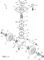
FIG. 1 is an exploded perspective view of a vertically adjustable caster wheel assembly. -
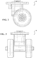
FIG. 2 is a side, plan view of the vertically adjustable caster wheel assembly. -
FIG. 3 is a front, plan view of the vertically adjustable caster wheel assembly. -
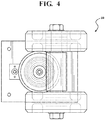
FIG. 4 is a top, plan view of the vertically adjustable caster wheel assembly. -
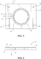
FIG. 5 is a top, plan view of a mounting member of the vertically adjustable caster wheel assembly. -
FIG. 6 is a side, plan view of the mounting member of the vertically adjustable caster wheel assembly. -
FIG. 7 is a side, plan view of an upper housing of the vertically adjustable caster wheel assembly. -
FIG. 8 is a top, plan view of the upper housing of the vertically adjustable caster wheel assembly. -
FIG. 9 is a side, plan view of a lower housing of the vertically adjustable caster wheel assembly. -
FIG. 10 is a rear, plan view of an axle housing of the vertically adjustable caster wheel assembly. -
FIG. 11 is a side, plan view of the axle housing of the vertically adjustable caster wheel assembly. -
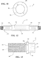
FIG. 12 is a side, plan view of an axle of the vertically adjustable caster wheel assembly. -
FIG. 13 is a side, plan view of an inner alignment post of the vertically adjustable caster wheel assembly. -
FIG. 14 is a top, plan view of the inner alignment post of the vertically adjustable caster wheel assembly. -
FIG. 15 is a top, plan view of a stop block of the vertically adjustable caster wheel assembly. -
FIG. 16 is a side, plan view of the stop block of the vertically adjustable caster wheel assembly. -
FIGS. 1-4 illustrate acaster wheel assembly 10 that can be vertically adjusted from the top of thecaster wheel assembly 10. As a result, the vertical height of thecaster wheel assembly 10 can be increased or decreased while thecaster wheel assembly 10 is attached to an industrial vehicle (not shown), such as a forklift truck. Consequently, the vertical height of thecaster wheel assembly 10 can be adjusted by accessing thecaster wheel assembly 10 through an aperture in the floor of the industrial vehicle, thereby avoiding the need to disassemble thecaster wheel assembly 10 or accessing thecaster wheel assembly 10 from underneath the industrial vehicle. - The
caster wheel assembly 10 can include a mountingplate 12, anupper housing 14, alower housing 16, anaxle housing 18, anaxle 20, aninner alignment post 22, astop block 24, and one ormore wheels 26. In order to connect thecaster wheel assembly 10 to the industrial vehicle, the mountingplate 12, as illustrated in detail inFIGS. 5-6 , can be made from any suitable material, such as steel. As shown, the mountingplate 12 has a substantially rectangular cuboid configuration, although other configurations are possible. To assist with mounting thecaster wheel assembly 10 to the industrial vehicle, the mountingplate 12 can be provided withfirst apertures 28 that extend through atop face 30 and abottom face 32 of the mountingplate 12. Eachfirst aperture 28 can be capable of receiving a conventional fastener (not shown), such as a screw, that extends through thefirst aperture 28 and is received by a corresponding aperture in a frame of the industrial vehicle. As shown, there are fourfirst apertures 28 that are positioned adjacent to four corners of the mountingplate 12. The number and positioning of thefirst apertures 28 can vary depending on the implementation. - To limit the amount of vertical adjustment provided by the
caster wheel assembly 10, thestop block 24 is mounted to the mountingplate 12 through twosecond apertures 34 and/or athird aperture 36 that extend through thetop face 30 and thebottom face 32 of the mountingplate 12, wherein thethird aperture 36 is between thesecond apertures 34. Thesecond apertures 34 are each capable of receiving a roll pin 38 (shown inFIG. 1 ), and thethird aperture 36 can receive a conventional fastener, such as a screw 40 (shown inFIG. 1 ). Thethird aperture 36 can have a diameter larger than diameters of thesecond apertures 34. - To assist with connecting the
upper housing 14 to the mountingplate 12, the mountingplate 12 can be provided with afourth aperture 42 that is centrally located and has a diameter than is slightly larger than an outer diameter of acenter region 64 of theupper housing 14. Theupper housing 14 and the mountingplate 12 can be welded together to form an integral unit. As shown inFIG. 6 , thefourth aperture 42 extends through the mountingplate 12 from thetop face 30 to thebottom face 32. As shown, the diameter of thefourth aperture 42 is substantially constant adjacent to thetop face 30 of the mountingplate 12 and tapers inward toward thebottom face 32 of the mountingplate 12, forming ashoulder 44 where the diameter of thefourth aperture 42 tapers inward. Thesecond apertures 34 and thethird aperture 36 can be linearly aligned near thefourth aperture 42 so that thestop block 24 can interact with thelower housing 16, as will be explained. - The
upper housing 14, shown inFIGS. 7-8 , is matingly received by thefourth aperture 42 in the mountingplate 12, wherein the outer diameter of theupper housing 14 can be larger at thefirst end 48 of theupper housing 14 so that afirst chamfer 58 can be seated against thetop face 30 of the mountingplate 12 when theupper housing 14 is connected to the mountingplate 12 via thefourth aperture 42. Asecond chamfer 60 can be formed at thesecond end 50 of theupper housing 14 where the outer diameter of theupper housing 14 tapers further. The outer diameter of theupper housing 14 can remain substantially constant between thefirst chamfer 58 and thesecond chamfer 60. Theupper housing 14 can have a substantially tubular configuration with abore 46 extending through theupper housing 14 that is coaxial with thefourth aperture 42 of the mountingplate 12. Theupper housing 14 can be fabricated from any suitable material, such as steel. - To prevent undesired vertical adjustment of the
caster wheel assembly 10 through rotation of theinner alignment post 22, thebore 46 extends between afirst end 48 and asecond end 50 of theupper housing 14. As shown, the diameter of thebore 46 is stepped so that thefirst end 48 and thesecond end 50 of theupper housing 14 are substantially the same, and acenter region 62 of thebore 46 is smaller than thefirst end 48 and thesecond end 50, defining afirst shoulder 52 and asecond shoulder 54. Thecenter region 62 can be provided with threading.Cutouts 56 can extend into theupper housing 14 approximately half of the distance between thefirst shoulder 52 and thesecond shoulder 54. Thecutouts 56 can have a substantially arcuate or C-shape cross-sectional configuration that is complementary tolegs 144 of a rotation restriction member 142 (shown inFIG. 1 ). - To allow vertical displacement of the
lower housing 16 relative to theupper housing 14, theupper housing 14 can be partially nested within abore 66 of thelower housing 16. Thelower housing 16 is illustrated in detail inFIG. 9 and can be made from any suitable material, such as steel. Thelower housing 16 can have a substantially tubular configuration with thebore 66 extending through thelower housing 16 from afirst end 68 to asecond end 70. Thebore 66 can be coaxially aligned with thebore 46 of theupper housing 14, and the diameter of thebore 66 may be stepped between thefirst end 68 and thesecond end 70 of thelower housing 16. As shown, the diameter of thebore 66 is stepped to defineshoulders snap ring 84, awear ring 86, aflexible seal 88, and a swivel bearing 90 (shown inFIG. 1 ) to allow for rotation of thelower housing 16 relative to theupper housing 14. - The stepped diameter of the
bore 66 of thelower housing 16 forms afirst shoulder 72 near thefirst end 68 of thelower housing 16. The diameter of thebore 66 between thefirst end 68 and thefirst shoulder 72 can be sized to house theflexible seal 88. Asecond shoulder 74 and a correspondingthird shoulder 76 are formed a short distance away from thefirst shoulder 72. The diameter of thebore 66 between thesecond shoulder 74 and thethird shoulder 76 can be sized to house thewear ring 86. Afourth shoulder 78 and a correspondingfifth shoulder 80 can also be formed between thefirst end 68 and thesecond end 70 of thelower housing 16. The diameter of thebore 66 between thefourth shoulder 78 and thefifth shoulder 80 can be sized to house thesnap ring 84. The diameter of thebore 66 between thefirst shoulder 72 and thesecond shoulder 74 and the diameter of thebore 66 between thesecond shoulder 74 and thethird shoulder 76 can be substantially the same and can be sized to be slightly larger than the outer diameter of thecenter region 64 of theupper housing 14. A sixth taperedshoulder 82 can be formed near thesecond end 70 of thelower housing 16. The diameter of thebore 66 between thefifth shoulder 80 and thesixth shoulder 82 can be sized to house theswivel bearing 90. - The
snap ring 84, thewear ring 86, and theflexible seal 88 can be made from any suitable material. For example, thesnap ring 84 could be made from a metal, such as steel, and thewear ring 86 and theflexible seal 88 could be made from nylon or rubber. As shown inFIG. 1 , thesnap ring 84 can have a substantially C-shaped configuration that is slightly larger than the diameter of thebore 66 of thelower housing 16 between thefirst end 68 and thefirst shoulder 72 of thelower housing 16. As a result, ends 108 of thesnap ring 84 can be close to touching or touching when thesnap ring 84 is disposed within thelower housing 16. Thewear ring 86 can have a substantially ring-like configuration with the exception of a cut 110 that forms ends to assist with inserting thewear ring 86 into thelower housing 16 between thesecond shoulder 74 and thethird shoulder 76. Theflexible seal 88 and the swivel bearing 90 can have substantially ring-like configurations. The swivel bearing 90 can be fabricated from any suitable material, such as steel, and have a thickness that is greater than a thickness of theflexible seal 88. The swivel bearing 90 can be provided with a lubricant that theflexible seal 88 assists with containing. - The
lower housing 16 can further include alip 92 adjacent to thefirst end 68, and arecess 94 formed on thesecond end 70. Thelip 92 can extend substantially perpendicular from anouter surface 96 of thelower housing 16 to interact with thestop block 24. Therecess 94 can have a substantially arcuate configuration, which allows theaxle housing 18 to be mounted and/or welded flush against thelower housing 16. - The
axle housing 18 is illustrated in detail inFIGS. 10-11 and can be made from any suitable material, such as steel. Theaxle housing 18 can have a substantially tubular configuration with abore 98 extending through theaxle housing 18 from afirst end 100 to asecond end 102. Theaxle housing 18 can have acutout 104 that allows theaxle housing 18 to be mounted and/or welded flush against thelower housing 16. As shown, thecutout 104 has a generally triangular configuration with two sides having a substantially linear configuration and a third side having a generally arcuate configuration. Theaxle housing 18 can also be provided with anaperture 106 that extends through theaxle housing 18 substantially perpendicular to thebore 98 of theaxle housing 18 and is in communication with thebore 98 of theaxle housing 18. Theaperture 106 can be spaced approximately half way between thefirst end 100 and thesecond end 102 of theaxle housing 18. - To provide for rotation of the
wheels 26, theaxle 20 is illustrated in detail inFIG. 12 and can be fabricated from any suitable material, such as steel. Theaxle 20 can be substantially solid with threading on afirst end 112 and asecond end 114, which allowslock nuts 116 to be secured to the first and second ends 112, 114 of theaxle 20. Acenter portion 118 of theaxle 20 can be disposed or press fit within thebore 98 of theaxle housing 18 and is sized to accommodate such. Thecenter portion 118 of theaxle 20 can be provided with anaperture 120 capable of receiving a drive pin 122 (shown inFIG. 1 ). When thecenter portion 118 of theaxle 20 is disposed within thebore 98 of theaxle housing 18, theaperture 120 of theaxle 20 aligns with theaperture 106 so that thedrive pin 122 can extend through theaxle 20 and theaxle housing 18 to prevent rotation of theaxle 20 relative to theaxle housing 18. - Two
intermediary portions 124 of theaxle 20 can be disposed between thecenter portion 118 and the first and second ends 112, 114, respectively. Theintermediary portions 124 can have substantially the same diameter, which can be less than the diameter of thecenter portion 118 and greater than the diameter of the first and second ends 112, 114. When thecenter portion 118 of theaxle 20 is disposed within thebore 98 of theaxle housing 18,wheel bearings 126 can be seated againstshoulders 128 formed between thecenter portion 118 and the first and second ends 112, 114 of theaxle 20, followed by thewheels 26,spacer tubes 130,wheel bearings 132,washers 134, and the lock nuts 116 (shown inFIG. 1 ). Thewheel bearings - To facilitate vertical adjustment of the
caster wheel assembly 10, theinner alignment post 22 is disposed within theupper housing 14 and thelower housing 16 so that theinner alignment post 22, theupper housing 14, and thelower housing 16 are concentric. Theinner alignment post 22 is illustrated in detail inFIGS. 13-14 and can be fabricated from any suitable material, such as steel. Theinner alignment post 22 can have a generally cylindrical configuration with a threadedfirst portion 140 that is configured for threadably engaging the threadedcenter region 62 of thebore 46 of theupper housing 14. The threadedfirst portion 140 can be provided withcutouts 146 in one end of theinner alignment post 22 that can have a substantially arcuate or C-shape cross-sectional configuration that is complementary to thelegs 144 of therotation restriction member 142. As shown, there are twocutouts 146 that are opposite one another and can be aligned with two of the fourcutouts 56 in thebore 46 of theupper housing 14. A counterboredaperture 148 capable of receiving a conventional fastener (not shown) can extend into the inner alignment post 22 from afirst end 150. - A
shoulder 158 formed on theinner alignment post 22 separates the threadedfirst portion 140 from asecond portion 156 of theinner alignment post 22. A chamfer orrecess 160 can be formed between the threadedfirst portion 140 and theshoulder 158. Theshoulder 158 can have a transverse cross-sectional dimension (e.g., a diameter) greater than a transverse cross-sectional dimension (e.g., a diameter) of the threadedfirst portion 140 and a transverse cross-sectional dimension (e.g., a diameter) of thesecond portion 156. Thesecond portion 156 of theinner alignment post 22 can be configured so that thesecond portion 156 can be secured within abore 162 of the swivel bearing 90 (shown inFIG. 1 ) via a friction fit with theshoulder 158 of theinner alignment post 22 resting on top of theswivel bearing 90. Anaperture 154 coaxially aligned with the counterboredaperture 148 can extend into thesecond portion 156 of the inner alignment post 22 from asecond end 152 of theinner alignment post 22. Theaperture 154 is capable of receiving a conventional fastener, such as a screw 138 (shown inFIG. 1 ). A washer 136 (shown inFIG. 1 ) can also be used at thesecond end 152 of theinner alignment post 22 with thescrew 138. - To prevent the
lower housing 16 from separating from theupper housing 14 through excessive rotation of theinner alignment post 22, thestop block 24 can be mounted to the mountingplate 12 adjacent to theupper housing 14. Thestop block 24 is illustrated in detail inFIGS. 15-16 and can be fabricated from any suitable material, such as steel or a polymer. Thestop block 24 can have a generally rectangular cuboid configuration with a generally arcuate configuration on a first side 164, which allows thestop block 24 to be mounted flush against theupper housing 14. Acounterbore 170 can extend through thestop block 24 from abottom end 168 to atop end 166, andapertures 172 can extend into thestop block 24 from thetop end 166. When thestop block 24 is positioned adjacent to theupper housing 14, theapertures 172 of thestop block 24 align with thesecond apertures 34 of the mountingplate 12 to allow insertion of the roll pins 38, and thecounterbore 170 of thestop block 24 aligns with thethird aperture 36 of the mountingplate 12 to allow insertion of thescrew 40. Alip 174 can protrude from the first side 164 of thestop block 24 near thebottom end 168 that can engage thelip 92 of thelower housing 16 when thecaster wheel assembly 10 is at its greatest vertical height. - Once at a desired vertical height, the
rotation restriction member 142 prevents rotation of theinner alignment post 22. As shown inFIG. 1 , therotation restriction member 142 is comprised of thelegs 144 and a base 176 that is substantially perpendicular to thelegs 144. Thelegs 144 can be mounted or welded to thebase 176. The base 176 can have a substantially disc-like configuration with anaperture 178 extending through a center of the base 176 that is capable of receiving a conventional fastener (not shown). As shown, there are twolegs 144 that are linearly aligned with theaperture 178. When therotation restriction member 142 is disposed within theupper housing 14, thebase 176 is seated against thefirst shoulder 52 formed in thebore 46 with thelegs 144 positioned within thecutouts 56 of thebore 46 andcutouts 146 of theinner alignment post 22. - To adjust the vertical height of the
caster wheel assembly 10, therotation restriction member 142 is removed from theupper housing 14. If thecaster wheel assembly 10 is attached to the industrial vehicle, the industrial vehicle can provide an aperture (not shown) in the floor of the industrial vehicle that allows access to therotation restriction member 142 from above, thereby obviating any need for disassembly of thecaster wheel assembly 10 and increasing the ease of operation in relation to known systems. Once therotation restriction member 142 has been removed, theinner alignment post 22 can be rotated. For example, in one embodiment, it is envisioned that rotation of theinner alignment post 22 may be effected via rotation of the fastener inserted into the aperture 148 (FIG. 13 ). - Because of the complementary threading in the
center region 62 of thebore 46 of theupper housing 14 and the threadedfirst portion 140 of theinner alignment post 22, rotation in a first direction causes the vertical height of thecaster wheel assembly 10 to increase and rotation in a second direction opposite the first direction causes the vertical height of thecaster wheel assembly 10 to decrease. Thelip 174 on thestop block 24 and thelip 92 on thelower housing 16 prevent the inner alignment post 22 from being rotated so far in the first direction that thelower housing 16 separates from theupper housing 14. - Once the desired vertical height of the
caster wheel assembly 10 has been obtained, therotation restriction member 142 is replaced so that thebase 176 is seated against thefirst shoulder 52 formed in thebore 46 and thelegs 144 positioned within thecutouts 56 of thebore 46 andcutouts 146 of theinner alignment post 22. A conventional fastener, such as a screw, can then be inserted into theaperture 178 of therotation restriction member 142 and the counterboredaperture 148 of theinner alignment post 22 to secure therotation restriction member 142 to theinner alignment post 22. - While the invention has been described in connection with certain embodiments, it is to be understood that the invention is not to be limited to the disclosed embodiments but, on the contrary, is intended to cover various modifications and equivalent arrangements included within the scope of the appended claims, which scope is to be accorded the broadest interpretation so as to encompass all such modifications and equivalent structures as is permitted under the law.
- In the preceding description, reference may be made to the spatial relationship between the various structures illustrated in the accompanying drawings, and to the spatial orientation of the structures. However, as will be recognized by those skilled in the art after a complete reading of this invention, the structures described herein may be positioned and oriented in any manner suitable for their intended purpose. Thus, the use of terms such as "above," "below," "upper," "lower," "inner," "outer," "upward," "downward," "inward," "outward," etc., should be understood to describe a relative relationship between structures and/or a spatial orientation of the structures. Those skilled in the art will also recognize that the use of such terms may be provided in the context of the illustrations provided by the corresponding figure(s).
- Additionally, terms such as "approximately," "generally," "substantially," and the like should be understood to allow for variations in any numerical range or concept with which they are associated. For example, it is intended that the use of terms such as "approximately" and "generally" should be understood to encompass variations on the order of 25%, or to allow for manufacturing tolerances and/or deviations in design.
Claims (15)
- An adjustable caster wheel assembly (10), comprising:a lower housing (16);an upper housing (14), the upper housing (14) including a threaded portion (62); andan alignment post (22) disposed within the upper housing (14) and coupled to the lower housing (16), the alignment post (22) including a threaded portion (140) configured and dimensioned for engagement with the threaded portion (62) of the upper housing (14) such that rotation of the alignment post (22) in a first direction causes separation of the upper housing (14) and the lower housing (16) to increase a height of the caster wheel assembly (10) and rotation of the alignment post (22) in a second direction causes approximation of the upper housing (14) and the lower housing (16) to decrease a height of the caster wheel assembly (10), characterised in that the upper housing (14) is partly disposed in the lower housing (16).
- The caster wheel assembly (10) of claim 1, wherein the lower housing (16), the upper housing (14), and the alignment post (22) are positioned in concentric relation.
- The caster wheel assembly (10) of claim 1, wherein the alignment post (22) is configured, dimensioned, and positioned such that the alignment post (22) is vertically accessible from above the upper housing (14).
- The caster wheel assembly (10) of claim 1, wherein the alignment post (22) includes a threaded first portion (140) and a second, non-threaded portion (156) spaced longitudinally from the first portion (140).
- The caster wheel assembly (10) of claim 4, wherein the alignment post (22) further includes a shoulder (158) positioned between the first portion (140) and the second portion (156).
- The caster wheel assembly (10) of claim 5, wherein the first portion (140) of the alignment post (22) defines a first diameter, the second portion (156) of the alignment post (22) defines a second diameter, and the shoulder (158) defines a third diameter, the third diameter being greater than the first and second diameters.
- The caster wheel assembly (10) of claim 4 further including a swivel bearing (90) positioned within the lower housing (16), the swivel bearing (90) including a bore (162) configured and dimensioned to receive the alignment post (22).
- The caster wheel assembly (10) of claim 7, wherein the second portion (156) of the alignment post (22) is configured and dimensioned for insertion into the bore (162) of the swivel bearing (90).
- The caster wheel assembly (10) of claim 8, wherein the second portion (156) of the alignment post (22) and the bore (162) of the swivel bearing (90) are configured and dimensioned such that the second portion (156) of the alignment post (22) is received by the bore (162) of the swivel bearing (90) in a friction fit.
- The caster wheel assembly (10) of claim 1 further including a rotation restriction member (142) configured and dimensioned for engagement with the alignment post (22) to restrict rotation of the alignment post (22).
- The caster wheel assembly (10) of claim 10, wherein the rotation restriction member (142) includes engagement structure configured and dimensioned for engagement with corresponding receiving structure formed on the alignment post (22).
- The caster wheel assembly (10) of claim 11, wherein the engagement structure includes a pair of legs (144), and the receiving structure includes a pair of longitudinal cutouts (56) configured and dimensioned to receive the legs (144).
- The caster wheel assembly (10) of claim 1, wherein the upper housing (14) includes opposing ends (48, 50) each defining openings that are equivalent in diameter and a bore (46) extending between the opposing ends (48, 50), the bore (46) including a center region (62) with a stepped configuration defining a diameter less than the diameters defined by the openings at the opposing ends (48, 50) of the upper housing (14) whereby the center region (62) of the bore (46) includes an internal shoulder (52, 54).
- The caster wheel assembly (10) of claim 13, wherein the center region (62) of the bore (46) includes a plurality of internal shoulders (52, 54) defining progressively larger diameters.
- The caster wheel assembly (10) of claim 1, further including a stop member (24) configured, dimensioned, and positioned for engagement with the lower housing (16) to limit vertical adjustment of the caster wheel assembly (10).
Priority Applications (1)
| Application Number | Priority Date | Filing Date | Title |
|---|---|---|---|
| PL18783342T PL3687833T3 (en) | 2017-09-26 | 2018-09-26 | Vertically adjustable caster wheel |
Applications Claiming Priority (2)
| Application Number | Priority Date | Filing Date | Title |
|---|---|---|---|
| US201762563149P | 2017-09-26 | 2017-09-26 | |
| PCT/US2018/052928 WO2019067597A1 (en) | 2017-09-26 | 2018-09-26 | Vertically adjustable caster wheel |
Publications (2)
| Publication Number | Publication Date |
|---|---|
| EP3687833A1 EP3687833A1 (en) | 2020-08-05 |
| EP3687833B1 true EP3687833B1 (en) | 2021-11-10 |
Family
ID=65808593
Family Applications (1)
| Application Number | Title | Priority Date | Filing Date |
|---|---|---|---|
| EP18783342.1A Active EP3687833B1 (en) | 2017-09-26 | 2018-09-26 | Vertically adjustable caster wheel |
Country Status (4)
| Country | Link |
|---|---|
| US (1) | US10717324B2 (en) |
| EP (1) | EP3687833B1 (en) |
| PL (1) | PL3687833T3 (en) |
| WO (1) | WO2019067597A1 (en) |
Families Citing this family (5)
| Publication number | Priority date | Publication date | Assignee | Title |
|---|---|---|---|---|
| EP3854606A4 (en) * | 2018-09-21 | 2023-03-22 | Nsk Ltd. | DRIVE WHEEL, CARRIAGE AND DEVICE |
| US10463152B1 (en) * | 2018-10-15 | 2019-11-05 | Marc S. Day | Multi-position easel |
| WO2021027572A1 (en) * | 2019-08-15 | 2021-02-18 | 燕山大学 | Active-passive differential series-parallel supporting leg, gravity closing-based series-parallel supporting leg and six-degree-of-freedom posture adjustment robot platform |
| US20240389505A1 (en) * | 2023-05-24 | 2024-11-28 | Deere & Company | Mower deck height of cut adjustment mechanism |
| KR102694294B1 (en) * | 2023-11-23 | 2024-08-12 | 여신동 | Double eccentric type caster |
Family Cites Families (47)
| Publication number | Priority date | Publication date | Assignee | Title |
|---|---|---|---|---|
| LU37243A1 (en) * | ||||
| US1480588A (en) * | 1921-11-23 | 1924-01-15 | Wise Mcclung Mfg Company | Adjustable wheel for vacuum cleaners |
| US1810971A (en) * | 1923-08-06 | 1931-06-23 | Delco Light Co | Adjustable caster |
| US1772314A (en) * | 1927-08-09 | 1930-08-05 | William T Hormes | Caster |
| US1780755A (en) * | 1928-04-23 | 1930-11-04 | Garden City Plating And Mfg Co | Roller or caster |
| GB568276A (en) * | 1943-08-19 | 1945-03-27 | Charles Ravenscroft Nalle | Adjustable caster |
| US2385154A (en) * | 1943-11-12 | 1945-09-18 | Charles R Nalle | Adjustable caster socket |
| US2425675A (en) | 1944-01-20 | 1947-08-12 | Charles R Nalle | Caster |
| US2592942A (en) * | 1950-11-24 | 1952-04-15 | Brunson Instr Co | Dustproof leveling screw |
| US2749564A (en) * | 1953-04-24 | 1956-06-12 | Carl E Tally | Attachment for sweeper |
| US4364148A (en) * | 1980-12-22 | 1982-12-21 | Sperry Corporation | Combination castor and jack means apparatus |
| DE3119649C2 (en) | 1981-05-16 | 1987-03-19 | Tente-Rollen Gmbh & Co, 5632 Wermelskirchen | Castor with a locking device |
| FR2580551B1 (en) * | 1985-04-18 | 1989-08-25 | Blain Rene | PIVOTING WHEEL WITH AUTOMATIC LOCK |
| DE3618448A1 (en) * | 1986-04-08 | 1987-10-22 | Loh Kg Rittal Werk | Castor which can be decelerated and is intended for a load-receiving, moveable supporting plate |
| US4789121A (en) | 1987-05-01 | 1988-12-06 | Edward D. Gidseg | System for supporting and adjusting refrigerators and the like |
| US4723633A (en) * | 1987-05-26 | 1988-02-09 | Waco International Corporation | Adjusting screw retainer |
| FR2622151B1 (en) * | 1987-10-21 | 1991-03-29 | Electricite De France | HANDLING ACCESSORY, PARTICULARLY FOR THE HANDLING OF A RETENTION CONTAINER FOR MV / LV TRANSFORMER |
| US4918783A (en) * | 1989-05-16 | 1990-04-24 | Jack Chu | Adjustable wheel structure |
| JPH0780401B2 (en) * | 1989-05-17 | 1995-08-30 | 株式会社オリイ | Casters with installation base |
| US5457849A (en) * | 1993-03-29 | 1995-10-17 | Tandem Computers Incorporated | Compact detachable dolly for heavy computer systems |
| US5332182A (en) * | 1993-04-08 | 1994-07-26 | Pitney Bowes Inc. | Adjustable leveling foot assembly |
| JP3035439B2 (en) * | 1994-02-16 | 2000-04-24 | フランスベッド株式会社 | Caster equipment |
| EP0697296A1 (en) * | 1994-08-18 | 1996-02-21 | Jollybo S.A. | Lift and transport device for heavy loads |
| US5881979A (en) * | 1997-06-04 | 1999-03-16 | Knoll, Inc. | Telescoping leveler |
| JP2000245555A (en) * | 1999-02-26 | 2000-09-12 | Misawa Homes Co Ltd | Furniture |
| JP2001233002A (en) * | 2000-02-28 | 2001-08-28 | Konica Corp | Caster with height adjusting function, paper feeding device carrying it, and image forming device |
| US20010049859A1 (en) | 2000-04-22 | 2001-12-13 | Scott Lewis | Caster wheel assembly |
| US20030041409A1 (en) * | 2001-06-28 | 2003-03-06 | Caporale John L. | Adjustable-height castor system |
| US20030061681A1 (en) * | 2001-10-01 | 2003-04-03 | Plate Jack R. | Adjustable kingpin caster |
| JP4009211B2 (en) * | 2002-06-21 | 2007-11-14 | 株式会社イトーキ | Caster height adjustment mechanism |
| US6796001B1 (en) * | 2002-07-31 | 2004-09-28 | Kason Industries, Inc. | Height adjustable support for food service equipment |
| US6839937B2 (en) * | 2002-09-25 | 2005-01-11 | Bush Industries, Inc. | Leveling system |
| KR100584557B1 (en) * | 2003-07-02 | 2006-05-30 | 삼성전자주식회사 | Caster |
| US7077369B2 (en) * | 2003-07-23 | 2006-07-18 | Hardin Optical Co. | Stable tripod for telescope |
| US6886216B2 (en) | 2003-09-30 | 2005-05-03 | Component Hardware Group, Inc. | Caster leg assembly with adjustment locking means |
| US7159829B1 (en) * | 2004-06-18 | 2007-01-09 | Kason Industries, Inc. | Height adjustable support for food service equipment |
| US20060075600A1 (en) | 2004-10-12 | 2006-04-13 | Dominic Dennis P | Vertically adjustable caster |
| US7350269B2 (en) | 2004-10-12 | 2008-04-01 | Dennis Paul Dominic | Adjustable caster and leveling assembly |
| US20070169307A1 (en) | 2006-01-26 | 2007-07-26 | Xerox Corporation | Adjustable castor assembly |
| US7571887B2 (en) * | 2007-12-07 | 2009-08-11 | Kason Industries, Inc. | Height adjustable support for food service equipment |
| US8136201B2 (en) * | 2009-03-31 | 2012-03-20 | General Electric Company | Leveling leg and wheel assembly for an appliance |
| US8443736B2 (en) * | 2010-06-15 | 2013-05-21 | Susan A. Martenson | Furniture-supported retractable platform assembly |
| US8424887B1 (en) | 2011-04-13 | 2013-04-23 | Superior Tire & Rubber Corp. | Top-accessible, height-adjustable industrial caster wheel |
| EP2909047B1 (en) | 2012-10-19 | 2019-08-14 | Ross Design & Engineering, Inc. | Vertically adjustable caster wheel apparatus |
| US9416483B1 (en) * | 2012-10-24 | 2016-08-16 | Anthony Freakes | Laundry machine leveling devices |
| JP6242664B2 (en) * | 2013-11-08 | 2017-12-06 | 株式会社内田洋行 | Height adjustment device, height adjustment parts and furniture |
| US10688826B2 (en) * | 2017-06-22 | 2020-06-23 | DoRodo, LLC | Adjustable caster assembly |
-
2018
- 2018-09-26 US US16/142,645 patent/US10717324B2/en active Active
- 2018-09-26 EP EP18783342.1A patent/EP3687833B1/en active Active
- 2018-09-26 WO PCT/US2018/052928 patent/WO2019067597A1/en not_active Ceased
- 2018-09-26 PL PL18783342T patent/PL3687833T3/en unknown
Also Published As
| Publication number | Publication date |
|---|---|
| US20190092095A1 (en) | 2019-03-28 |
| PL3687833T4 (en) | 2022-04-19 |
| WO2019067597A1 (en) | 2019-04-04 |
| US10717324B2 (en) | 2020-07-21 |
| EP3687833A1 (en) | 2020-08-05 |
| PL3687833T3 (en) | 2022-04-19 |
Similar Documents
| Publication | Publication Date | Title |
|---|---|---|
| US10717324B2 (en) | Vertically adjustable caster wheel | |
| US11447106B2 (en) | Jack assembly | |
| US11420319B2 (en) | Platform extension mechanism | |
| US8839487B2 (en) | Vertically adjustable caster wheel apparatus | |
| US8943648B2 (en) | Adjustable support device with multiple rolling elements | |
| US20040195745A1 (en) | Apparatus, system and method for a vehicle suspenstion system | |
| US10543768B2 (en) | Adjustable armrest systems and methods for a material handling vehicle | |
| EP0791483B1 (en) | Directional control caster assembly | |
| US4884898A (en) | Linear motion pillow block including fine tuning features | |
| US9051965B1 (en) | Eccentric bearing assemblies for swivel casters | |
| US20030061681A1 (en) | Adjustable kingpin caster | |
| EP4688543A1 (en) | Kingpin assembly | |
| US20100038517A1 (en) | Adjustable caster of indoor cook stove | |
| US20120267488A1 (en) | Adjustable support device with multiple rolling elements | |
| US20150176686A1 (en) | Anti-rotation device for actuators | |
| CN213861720U (en) | Universal wheel assembly with height adjusting function | |
| US8550433B2 (en) | Adjustable column system and method | |
| US20130306413A1 (en) | Double acting fluid cylinder lock | |
| US2723415A (en) | Caster wheel | |
| EP2162297B1 (en) | Running gear | |
| CN219276645U (en) | Adjustable rolling device of shaping box | |
| US20130075678A1 (en) | Low profile jack | |
| CN220600195U (en) | Double-thread bolt assembly | |
| US20060010646A1 (en) | Low profile caster assembly | |
| CN121441028A (en) | Hub motor assembly tooling |
Legal Events
| Date | Code | Title | Description |
|---|---|---|---|
| STAA | Information on the status of an ep patent application or granted ep patent |
Free format text: STATUS: UNKNOWN |
|
| STAA | Information on the status of an ep patent application or granted ep patent |
Free format text: STATUS: THE INTERNATIONAL PUBLICATION HAS BEEN MADE |
|
| PUAI | Public reference made under article 153(3) epc to a published international application that has entered the european phase |
Free format text: ORIGINAL CODE: 0009012 |
|
| STAA | Information on the status of an ep patent application or granted ep patent |
Free format text: STATUS: REQUEST FOR EXAMINATION WAS MADE |
|
| 17P | Request for examination filed |
Effective date: 20200326 |
|
| AK | Designated contracting states |
Kind code of ref document: A1 Designated state(s): AL AT BE BG CH CY CZ DE DK EE ES FI FR GB GR HR HU IE IS IT LI LT LU LV MC MK MT NL NO PL PT RO RS SE SI SK SM TR |
|
| AX | Request for extension of the european patent |
Extension state: BA ME |
|
| DAV | Request for validation of the european patent (deleted) | ||
| DAX | Request for extension of the european patent (deleted) | ||
| GRAP | Despatch of communication of intention to grant a patent |
Free format text: ORIGINAL CODE: EPIDOSNIGR1 |
|
| STAA | Information on the status of an ep patent application or granted ep patent |
Free format text: STATUS: GRANT OF PATENT IS INTENDED |
|
| INTG | Intention to grant announced |
Effective date: 20210604 |
|
| GRAS | Grant fee paid |
Free format text: ORIGINAL CODE: EPIDOSNIGR3 |
|
| GRAA | (expected) grant |
Free format text: ORIGINAL CODE: 0009210 |
|
| STAA | Information on the status of an ep patent application or granted ep patent |
Free format text: STATUS: THE PATENT HAS BEEN GRANTED |
|
| AK | Designated contracting states |
Kind code of ref document: B1 Designated state(s): AL AT BE BG CH CY CZ DE DK EE ES FI FR GB GR HR HU IE IS IT LI LT LU LV MC MK MT NL NO PL PT RO RS SE SI SK SM TR |
|
| REG | Reference to a national code |
Ref country code: GB Ref legal event code: FG4D |
|
| REG | Reference to a national code |
Ref country code: AT Ref legal event code: REF Ref document number: 1445745 Country of ref document: AT Kind code of ref document: T Effective date: 20211115 Ref country code: CH Ref legal event code: EP |
|
| REG | Reference to a national code |
Ref country code: DE Ref legal event code: R096 Ref document number: 602018026564 Country of ref document: DE |
|
| REG | Reference to a national code |
Ref country code: IE Ref legal event code: FG4D |
|
| REG | Reference to a national code |
Ref country code: NL Ref legal event code: FP |
|
| REG | Reference to a national code |
Ref country code: SE Ref legal event code: TRGR |
|
| REG | Reference to a national code |
Ref country code: LT Ref legal event code: MG9D |
|
| REG | Reference to a national code |
Ref country code: AT Ref legal event code: MK05 Ref document number: 1445745 Country of ref document: AT Kind code of ref document: T Effective date: 20211110 |
|
| PG25 | Lapsed in a contracting state [announced via postgrant information from national office to epo] |
Ref country code: RS Free format text: LAPSE BECAUSE OF FAILURE TO SUBMIT A TRANSLATION OF THE DESCRIPTION OR TO PAY THE FEE WITHIN THE PRESCRIBED TIME-LIMIT Effective date: 20211110 Ref country code: LT Free format text: LAPSE BECAUSE OF FAILURE TO SUBMIT A TRANSLATION OF THE DESCRIPTION OR TO PAY THE FEE WITHIN THE PRESCRIBED TIME-LIMIT Effective date: 20211110 Ref country code: FI Free format text: LAPSE BECAUSE OF FAILURE TO SUBMIT A TRANSLATION OF THE DESCRIPTION OR TO PAY THE FEE WITHIN THE PRESCRIBED TIME-LIMIT Effective date: 20211110 Ref country code: BG Free format text: LAPSE BECAUSE OF FAILURE TO SUBMIT A TRANSLATION OF THE DESCRIPTION OR TO PAY THE FEE WITHIN THE PRESCRIBED TIME-LIMIT Effective date: 20220210 Ref country code: AT Free format text: LAPSE BECAUSE OF FAILURE TO SUBMIT A TRANSLATION OF THE DESCRIPTION OR TO PAY THE FEE WITHIN THE PRESCRIBED TIME-LIMIT Effective date: 20211110 |
|
| PG25 | Lapsed in a contracting state [announced via postgrant information from national office to epo] |
Ref country code: IS Free format text: LAPSE BECAUSE OF FAILURE TO SUBMIT A TRANSLATION OF THE DESCRIPTION OR TO PAY THE FEE WITHIN THE PRESCRIBED TIME-LIMIT Effective date: 20220310 Ref country code: PT Free format text: LAPSE BECAUSE OF FAILURE TO SUBMIT A TRANSLATION OF THE DESCRIPTION OR TO PAY THE FEE WITHIN THE PRESCRIBED TIME-LIMIT Effective date: 20220310 Ref country code: NO Free format text: LAPSE BECAUSE OF FAILURE TO SUBMIT A TRANSLATION OF THE DESCRIPTION OR TO PAY THE FEE WITHIN THE PRESCRIBED TIME-LIMIT Effective date: 20220210 Ref country code: LV Free format text: LAPSE BECAUSE OF FAILURE TO SUBMIT A TRANSLATION OF THE DESCRIPTION OR TO PAY THE FEE WITHIN THE PRESCRIBED TIME-LIMIT Effective date: 20211110 Ref country code: HR Free format text: LAPSE BECAUSE OF FAILURE TO SUBMIT A TRANSLATION OF THE DESCRIPTION OR TO PAY THE FEE WITHIN THE PRESCRIBED TIME-LIMIT Effective date: 20211110 Ref country code: GR Free format text: LAPSE BECAUSE OF FAILURE TO SUBMIT A TRANSLATION OF THE DESCRIPTION OR TO PAY THE FEE WITHIN THE PRESCRIBED TIME-LIMIT Effective date: 20220211 Ref country code: ES Free format text: LAPSE BECAUSE OF FAILURE TO SUBMIT A TRANSLATION OF THE DESCRIPTION OR TO PAY THE FEE WITHIN THE PRESCRIBED TIME-LIMIT Effective date: 20211110 |
|
| PG25 | Lapsed in a contracting state [announced via postgrant information from national office to epo] |
Ref country code: SM Free format text: LAPSE BECAUSE OF FAILURE TO SUBMIT A TRANSLATION OF THE DESCRIPTION OR TO PAY THE FEE WITHIN THE PRESCRIBED TIME-LIMIT Effective date: 20211110 Ref country code: SK Free format text: LAPSE BECAUSE OF FAILURE TO SUBMIT A TRANSLATION OF THE DESCRIPTION OR TO PAY THE FEE WITHIN THE PRESCRIBED TIME-LIMIT Effective date: 20211110 Ref country code: RO Free format text: LAPSE BECAUSE OF FAILURE TO SUBMIT A TRANSLATION OF THE DESCRIPTION OR TO PAY THE FEE WITHIN THE PRESCRIBED TIME-LIMIT Effective date: 20211110 Ref country code: EE Free format text: LAPSE BECAUSE OF FAILURE TO SUBMIT A TRANSLATION OF THE DESCRIPTION OR TO PAY THE FEE WITHIN THE PRESCRIBED TIME-LIMIT Effective date: 20211110 Ref country code: DK Free format text: LAPSE BECAUSE OF FAILURE TO SUBMIT A TRANSLATION OF THE DESCRIPTION OR TO PAY THE FEE WITHIN THE PRESCRIBED TIME-LIMIT Effective date: 20211110 Ref country code: CZ Free format text: LAPSE BECAUSE OF FAILURE TO SUBMIT A TRANSLATION OF THE DESCRIPTION OR TO PAY THE FEE WITHIN THE PRESCRIBED TIME-LIMIT Effective date: 20211110 |
|
| REG | Reference to a national code |
Ref country code: DE Ref legal event code: R097 Ref document number: 602018026564 Country of ref document: DE |
|
| PLBE | No opposition filed within time limit |
Free format text: ORIGINAL CODE: 0009261 |
|
| STAA | Information on the status of an ep patent application or granted ep patent |
Free format text: STATUS: NO OPPOSITION FILED WITHIN TIME LIMIT |
|
| 26N | No opposition filed |
Effective date: 20220811 |
|
| PG25 | Lapsed in a contracting state [announced via postgrant information from national office to epo] |
Ref country code: AL Free format text: LAPSE BECAUSE OF FAILURE TO SUBMIT A TRANSLATION OF THE DESCRIPTION OR TO PAY THE FEE WITHIN THE PRESCRIBED TIME-LIMIT Effective date: 20211110 |
|
| PG25 | Lapsed in a contracting state [announced via postgrant information from national office to epo] |
Ref country code: SI Free format text: LAPSE BECAUSE OF FAILURE TO SUBMIT A TRANSLATION OF THE DESCRIPTION OR TO PAY THE FEE WITHIN THE PRESCRIBED TIME-LIMIT Effective date: 20211110 |
|
| PG25 | Lapsed in a contracting state [announced via postgrant information from national office to epo] |
Ref country code: MC Free format text: LAPSE BECAUSE OF FAILURE TO SUBMIT A TRANSLATION OF THE DESCRIPTION OR TO PAY THE FEE WITHIN THE PRESCRIBED TIME-LIMIT Effective date: 20211110 |
|
| REG | Reference to a national code |
Ref country code: CH Ref legal event code: PL |
|
| PG25 | Lapsed in a contracting state [announced via postgrant information from national office to epo] |
Ref country code: LU Free format text: LAPSE BECAUSE OF NON-PAYMENT OF DUE FEES Effective date: 20220926 |
|
| P01 | Opt-out of the competence of the unified patent court (upc) registered |
Effective date: 20230609 |
|
| P02 | Opt-out of the competence of the unified patent court (upc) changed |
Effective date: 20230621 |
|
| PG25 | Lapsed in a contracting state [announced via postgrant information from national office to epo] |
Ref country code: LI Free format text: LAPSE BECAUSE OF NON-PAYMENT OF DUE FEES Effective date: 20220930 Ref country code: CH Free format text: LAPSE BECAUSE OF NON-PAYMENT OF DUE FEES Effective date: 20220930 |
|
| PG25 | Lapsed in a contracting state [announced via postgrant information from national office to epo] |
Ref country code: CY Free format text: LAPSE BECAUSE OF FAILURE TO SUBMIT A TRANSLATION OF THE DESCRIPTION OR TO PAY THE FEE WITHIN THE PRESCRIBED TIME-LIMIT Effective date: 20211110 |
|
| PG25 | Lapsed in a contracting state [announced via postgrant information from national office to epo] |
Ref country code: MK Free format text: LAPSE BECAUSE OF FAILURE TO SUBMIT A TRANSLATION OF THE DESCRIPTION OR TO PAY THE FEE WITHIN THE PRESCRIBED TIME-LIMIT Effective date: 20211110 Ref country code: HU Free format text: LAPSE BECAUSE OF FAILURE TO SUBMIT A TRANSLATION OF THE DESCRIPTION OR TO PAY THE FEE WITHIN THE PRESCRIBED TIME-LIMIT; INVALID AB INITIO Effective date: 20180926 |
|
| PG25 | Lapsed in a contracting state [announced via postgrant information from national office to epo] |
Ref country code: TR Free format text: LAPSE BECAUSE OF FAILURE TO SUBMIT A TRANSLATION OF THE DESCRIPTION OR TO PAY THE FEE WITHIN THE PRESCRIBED TIME-LIMIT Effective date: 20211110 |
|
| PG25 | Lapsed in a contracting state [announced via postgrant information from national office to epo] |
Ref country code: MT Free format text: LAPSE BECAUSE OF FAILURE TO SUBMIT A TRANSLATION OF THE DESCRIPTION OR TO PAY THE FEE WITHIN THE PRESCRIBED TIME-LIMIT Effective date: 20211110 |
|
| PGFP | Annual fee paid to national office [announced via postgrant information from national office to epo] |
Ref country code: DE Payment date: 20250929 Year of fee payment: 8 |
|
| PGFP | Annual fee paid to national office [announced via postgrant information from national office to epo] |
Ref country code: PL Payment date: 20250903 Year of fee payment: 8 Ref country code: NL Payment date: 20250926 Year of fee payment: 8 Ref country code: IT Payment date: 20250919 Year of fee payment: 8 |
|
| PGFP | Annual fee paid to national office [announced via postgrant information from national office to epo] |
Ref country code: BE Payment date: 20250929 Year of fee payment: 8 Ref country code: GB Payment date: 20250929 Year of fee payment: 8 |
|
| PGFP | Annual fee paid to national office [announced via postgrant information from national office to epo] |
Ref country code: FR Payment date: 20250925 Year of fee payment: 8 |
|
| PGFP | Annual fee paid to national office [announced via postgrant information from national office to epo] |
Ref country code: SE Payment date: 20250927 Year of fee payment: 8 |
|
| PGFP | Annual fee paid to national office [announced via postgrant information from national office to epo] |
Ref country code: IE Payment date: 20250929 Year of fee payment: 8 |