EP3687616B1 - Indwelling catheter, catheter introducer mating device and system comprising both - Google Patents
Indwelling catheter, catheter introducer mating device and system comprising both Download PDFInfo
- Publication number
- EP3687616B1 EP3687616B1 EP18792715.7A EP18792715A EP3687616B1 EP 3687616 B1 EP3687616 B1 EP 3687616B1 EP 18792715 A EP18792715 A EP 18792715A EP 3687616 B1 EP3687616 B1 EP 3687616B1
- Authority
- EP
- European Patent Office
- Prior art keywords
- catheter
- sectional area
- proximal end
- retainer portion
- catheter system
- Prior art date
- Legal status (The legal status is an assumption and is not a legal conclusion. Google has not performed a legal analysis and makes no representation as to the accuracy of the status listed.)
- Active
Links
Images







Classifications
-
- A—HUMAN NECESSITIES
- A61—MEDICAL OR VETERINARY SCIENCE; HYGIENE
- A61M—DEVICES FOR INTRODUCING MEDIA INTO, OR ONTO, THE BODY; DEVICES FOR TRANSDUCING BODY MEDIA OR FOR TAKING MEDIA FROM THE BODY; DEVICES FOR PRODUCING OR ENDING SLEEP OR STUPOR
- A61M25/00—Catheters; Hollow probes
- A61M25/0017—Catheters; Hollow probes specially adapted for long-term hygiene care, e.g. urethral or indwelling catheters to prevent infections
-
- A—HUMAN NECESSITIES
- A61—MEDICAL OR VETERINARY SCIENCE; HYGIENE
- A61B—DIAGNOSIS; SURGERY; IDENTIFICATION
- A61B5/00—Measuring for diagnostic purposes; Identification of persons
- A61B5/0002—Remote monitoring of patients using telemetry, e.g. transmission of vital signals via a communication network
- A61B5/0015—Remote monitoring of patients using telemetry, e.g. transmission of vital signals via a communication network characterised by features of the telemetry system
- A61B5/0022—Monitoring a patient using a global network, e.g. telephone networks, internet
-
- A—HUMAN NECESSITIES
- A61—MEDICAL OR VETERINARY SCIENCE; HYGIENE
- A61B—DIAGNOSIS; SURGERY; IDENTIFICATION
- A61B5/00—Measuring for diagnostic purposes; Identification of persons
- A61B5/03—Measuring fluid pressure within the body other than blood pressure, e.g. cerebral pressure ; Measuring pressure in body tissues or organs
- A61B5/036—Measuring fluid pressure within the body other than blood pressure, e.g. cerebral pressure ; Measuring pressure in body tissues or organs by means introduced into body tracts
-
- A—HUMAN NECESSITIES
- A61—MEDICAL OR VETERINARY SCIENCE; HYGIENE
- A61B—DIAGNOSIS; SURGERY; IDENTIFICATION
- A61B5/00—Measuring for diagnostic purposes; Identification of persons
- A61B5/20—Measuring for diagnostic purposes; Identification of persons for measuring urological functions restricted to the evaluation of the urinary system
- A61B5/202—Assessing bladder functions, e.g. incontinence assessment
- A61B5/204—Determining bladder volume
-
- A—HUMAN NECESSITIES
- A61—MEDICAL OR VETERINARY SCIENCE; HYGIENE
- A61B—DIAGNOSIS; SURGERY; IDENTIFICATION
- A61B5/00—Measuring for diagnostic purposes; Identification of persons
- A61B5/20—Measuring for diagnostic purposes; Identification of persons for measuring urological functions restricted to the evaluation of the urinary system
- A61B5/202—Assessing bladder functions, e.g. incontinence assessment
- A61B5/205—Determining bladder or urethral pressure
-
- A—HUMAN NECESSITIES
- A61—MEDICAL OR VETERINARY SCIENCE; HYGIENE
- A61B—DIAGNOSIS; SURGERY; IDENTIFICATION
- A61B5/00—Measuring for diagnostic purposes; Identification of persons
- A61B5/68—Arrangements of detecting, measuring or recording means, e.g. sensors, in relation to patient
- A61B5/6846—Arrangements of detecting, measuring or recording means, e.g. sensors, in relation to patient specially adapted to be brought in contact with an internal body part, i.e. invasive
- A61B5/6847—Arrangements of detecting, measuring or recording means, e.g. sensors, in relation to patient specially adapted to be brought in contact with an internal body part, i.e. invasive mounted on an invasive device
- A61B5/6852—Catheters
-
- A—HUMAN NECESSITIES
- A61—MEDICAL OR VETERINARY SCIENCE; HYGIENE
- A61B—DIAGNOSIS; SURGERY; IDENTIFICATION
- A61B5/00—Measuring for diagnostic purposes; Identification of persons
- A61B5/68—Arrangements of detecting, measuring or recording means, e.g. sensors, in relation to patient
- A61B5/6846—Arrangements of detecting, measuring or recording means, e.g. sensors, in relation to patient specially adapted to be brought in contact with an internal body part, i.e. invasive
- A61B5/6847—Arrangements of detecting, measuring or recording means, e.g. sensors, in relation to patient specially adapted to be brought in contact with an internal body part, i.e. invasive mounted on an invasive device
- A61B5/6852—Catheters
- A61B5/6858—Catheters with a distal basket, e.g. expandable basket
-
- A—HUMAN NECESSITIES
- A61—MEDICAL OR VETERINARY SCIENCE; HYGIENE
- A61B—DIAGNOSIS; SURGERY; IDENTIFICATION
- A61B5/00—Measuring for diagnostic purposes; Identification of persons
- A61B5/68—Arrangements of detecting, measuring or recording means, e.g. sensors, in relation to patient
- A61B5/6846—Arrangements of detecting, measuring or recording means, e.g. sensors, in relation to patient specially adapted to be brought in contact with an internal body part, i.e. invasive
- A61B5/6867—Arrangements of detecting, measuring or recording means, e.g. sensors, in relation to patient specially adapted to be brought in contact with an internal body part, i.e. invasive specially adapted to be attached or implanted in a specific body part
- A61B5/6874—Bladder
-
- A—HUMAN NECESSITIES
- A61—MEDICAL OR VETERINARY SCIENCE; HYGIENE
- A61B—DIAGNOSIS; SURGERY; IDENTIFICATION
- A61B5/00—Measuring for diagnostic purposes; Identification of persons
- A61B5/74—Details of notification to user or communication with user or patient; User input means
- A61B5/746—Alarms related to a physiological condition, e.g. details of setting alarm thresholds or avoiding false alarms
-
- A—HUMAN NECESSITIES
- A61—MEDICAL OR VETERINARY SCIENCE; HYGIENE
- A61F—FILTERS IMPLANTABLE INTO BLOOD VESSELS; PROSTHESES; DEVICES PROVIDING PATENCY TO, OR PREVENTING COLLAPSING OF, TUBULAR STRUCTURES OF THE BODY, e.g. STENTS; ORTHOPAEDIC, NURSING OR CONTRACEPTIVE DEVICES; FOMENTATION; TREATMENT OR PROTECTION OF EYES OR EARS; BANDAGES, DRESSINGS OR ABSORBENT PADS; FIRST-AID KITS
- A61F2/00—Filters implantable into blood vessels; Prostheses, i.e. artificial substitutes or replacements for parts of the body; Appliances for connecting them with the body; Devices providing patency to, or preventing collapsing of, tubular structures of the body, e.g. stents
- A61F2/0004—Closure means for urethra or rectum, i.e. anti-incontinence devices or support slings against pelvic prolapse
- A61F2/0022—Closure means for urethra or rectum, i.e. anti-incontinence devices or support slings against pelvic prolapse placed deep in the body opening
-
- A—HUMAN NECESSITIES
- A61—MEDICAL OR VETERINARY SCIENCE; HYGIENE
- A61M—DEVICES FOR INTRODUCING MEDIA INTO, OR ONTO, THE BODY; DEVICES FOR TRANSDUCING BODY MEDIA OR FOR TAKING MEDIA FROM THE BODY; DEVICES FOR PRODUCING OR ENDING SLEEP OR STUPOR
- A61M25/00—Catheters; Hollow probes
- A61M25/01—Introducing, guiding, advancing, emplacing or holding catheters
- A61M25/0105—Steering means as part of the catheter or advancing means; Markers for positioning
- A61M25/0113—Mechanical advancing means, e.g. catheter dispensers
-
- A—HUMAN NECESSITIES
- A61—MEDICAL OR VETERINARY SCIENCE; HYGIENE
- A61F—FILTERS IMPLANTABLE INTO BLOOD VESSELS; PROSTHESES; DEVICES PROVIDING PATENCY TO, OR PREVENTING COLLAPSING OF, TUBULAR STRUCTURES OF THE BODY, e.g. STENTS; ORTHOPAEDIC, NURSING OR CONTRACEPTIVE DEVICES; FOMENTATION; TREATMENT OR PROTECTION OF EYES OR EARS; BANDAGES, DRESSINGS OR ABSORBENT PADS; FIRST-AID KITS
- A61F2/00—Filters implantable into blood vessels; Prostheses, i.e. artificial substitutes or replacements for parts of the body; Appliances for connecting them with the body; Devices providing patency to, or preventing collapsing of, tubular structures of the body, e.g. stents
- A61F2/02—Prostheses implantable into the body
- A61F2/04—Hollow or tubular parts of organs, e.g. bladders, tracheae, bronchi or bile ducts
- A61F2002/047—Urethrae
-
- A—HUMAN NECESSITIES
- A61—MEDICAL OR VETERINARY SCIENCE; HYGIENE
- A61F—FILTERS IMPLANTABLE INTO BLOOD VESSELS; PROSTHESES; DEVICES PROVIDING PATENCY TO, OR PREVENTING COLLAPSING OF, TUBULAR STRUCTURES OF THE BODY, e.g. STENTS; ORTHOPAEDIC, NURSING OR CONTRACEPTIVE DEVICES; FOMENTATION; TREATMENT OR PROTECTION OF EYES OR EARS; BANDAGES, DRESSINGS OR ABSORBENT PADS; FIRST-AID KITS
- A61F2210/00—Particular material properties of prostheses classified in groups A61F2/00 - A61F2/26 or A61F2/82 or A61F9/00 or A61F11/00 or subgroups thereof
- A61F2210/009—Particular material properties of prostheses classified in groups A61F2/00 - A61F2/26 or A61F2/82 or A61F9/00 or A61F11/00 or subgroups thereof magnetic
-
- A—HUMAN NECESSITIES
- A61—MEDICAL OR VETERINARY SCIENCE; HYGIENE
- A61F—FILTERS IMPLANTABLE INTO BLOOD VESSELS; PROSTHESES; DEVICES PROVIDING PATENCY TO, OR PREVENTING COLLAPSING OF, TUBULAR STRUCTURES OF THE BODY, e.g. STENTS; ORTHOPAEDIC, NURSING OR CONTRACEPTIVE DEVICES; FOMENTATION; TREATMENT OR PROTECTION OF EYES OR EARS; BANDAGES, DRESSINGS OR ABSORBENT PADS; FIRST-AID KITS
- A61F2220/00—Fixations or connections for prostheses classified in groups A61F2/00 - A61F2/26 or A61F2/82 or A61F9/00 or A61F11/00 or subgroups thereof
- A61F2220/0008—Fixation appliances for connecting prostheses to the body
-
- A—HUMAN NECESSITIES
- A61—MEDICAL OR VETERINARY SCIENCE; HYGIENE
- A61F—FILTERS IMPLANTABLE INTO BLOOD VESSELS; PROSTHESES; DEVICES PROVIDING PATENCY TO, OR PREVENTING COLLAPSING OF, TUBULAR STRUCTURES OF THE BODY, e.g. STENTS; ORTHOPAEDIC, NURSING OR CONTRACEPTIVE DEVICES; FOMENTATION; TREATMENT OR PROTECTION OF EYES OR EARS; BANDAGES, DRESSINGS OR ABSORBENT PADS; FIRST-AID KITS
- A61F2220/00—Fixations or connections for prostheses classified in groups A61F2/00 - A61F2/26 or A61F2/82 or A61F9/00 or A61F11/00 or subgroups thereof
- A61F2220/0025—Connections or couplings between prosthetic parts, e.g. between modular parts; Connecting elements
- A61F2220/0033—Connections or couplings between prosthetic parts, e.g. between modular parts; Connecting elements made by longitudinally pushing a protrusion into a complementary-shaped recess, e.g. held by friction fit
-
- A—HUMAN NECESSITIES
- A61—MEDICAL OR VETERINARY SCIENCE; HYGIENE
- A61F—FILTERS IMPLANTABLE INTO BLOOD VESSELS; PROSTHESES; DEVICES PROVIDING PATENCY TO, OR PREVENTING COLLAPSING OF, TUBULAR STRUCTURES OF THE BODY, e.g. STENTS; ORTHOPAEDIC, NURSING OR CONTRACEPTIVE DEVICES; FOMENTATION; TREATMENT OR PROTECTION OF EYES OR EARS; BANDAGES, DRESSINGS OR ABSORBENT PADS; FIRST-AID KITS
- A61F2250/00—Special features of prostheses classified in groups A61F2/00 - A61F2/26 or A61F2/82 or A61F9/00 or A61F11/00 or subgroups thereof
- A61F2250/0001—Means for transferring electromagnetic energy to implants
- A61F2250/0002—Means for transferring electromagnetic energy to implants for data transfer
-
- A—HUMAN NECESSITIES
- A61—MEDICAL OR VETERINARY SCIENCE; HYGIENE
- A61M—DEVICES FOR INTRODUCING MEDIA INTO, OR ONTO, THE BODY; DEVICES FOR TRANSDUCING BODY MEDIA OR FOR TAKING MEDIA FROM THE BODY; DEVICES FOR PRODUCING OR ENDING SLEEP OR STUPOR
- A61M25/00—Catheters; Hollow probes
- A61M2025/0001—Catheters; Hollow probes for pressure measurement
- A61M2025/0002—Catheters; Hollow probes for pressure measurement with a pressure sensor at the distal end
-
- A—HUMAN NECESSITIES
- A61—MEDICAL OR VETERINARY SCIENCE; HYGIENE
- A61M—DEVICES FOR INTRODUCING MEDIA INTO, OR ONTO, THE BODY; DEVICES FOR TRANSDUCING BODY MEDIA OR FOR TAKING MEDIA FROM THE BODY; DEVICES FOR PRODUCING OR ENDING SLEEP OR STUPOR
- A61M39/00—Tubes, tube connectors, tube couplings, valves, access sites or the like, specially adapted for medical use
- A61M39/22—Valves or arrangement of valves
- A61M2039/226—Spindles or actuating means
-
- A—HUMAN NECESSITIES
- A61—MEDICAL OR VETERINARY SCIENCE; HYGIENE
- A61M—DEVICES FOR INTRODUCING MEDIA INTO, OR ONTO, THE BODY; DEVICES FOR TRANSDUCING BODY MEDIA OR FOR TAKING MEDIA FROM THE BODY; DEVICES FOR PRODUCING OR ENDING SLEEP OR STUPOR
- A61M39/00—Tubes, tube connectors, tube couplings, valves, access sites or the like, specially adapted for medical use
- A61M39/22—Valves or arrangement of valves
- A61M39/24—Check- or non-return valves
- A61M2039/2473—Valve comprising a non-deformable, movable element, e.g. ball-valve, valve with movable stopper or reciprocating element
-
- A—HUMAN NECESSITIES
- A61—MEDICAL OR VETERINARY SCIENCE; HYGIENE
- A61M—DEVICES FOR INTRODUCING MEDIA INTO, OR ONTO, THE BODY; DEVICES FOR TRANSDUCING BODY MEDIA OR FOR TAKING MEDIA FROM THE BODY; DEVICES FOR PRODUCING OR ENDING SLEEP OR STUPOR
- A61M39/00—Tubes, tube connectors, tube couplings, valves, access sites or the like, specially adapted for medical use
- A61M39/22—Valves or arrangement of valves
- A61M39/24—Check- or non-return valves
- A61M2039/2473—Valve comprising a non-deformable, movable element, e.g. ball-valve, valve with movable stopper or reciprocating element
- A61M2039/2486—Guided stem, e.g. reciprocating stopper
-
- A—HUMAN NECESSITIES
- A61—MEDICAL OR VETERINARY SCIENCE; HYGIENE
- A61M—DEVICES FOR INTRODUCING MEDIA INTO, OR ONTO, THE BODY; DEVICES FOR TRANSDUCING BODY MEDIA OR FOR TAKING MEDIA FROM THE BODY; DEVICES FOR PRODUCING OR ENDING SLEEP OR STUPOR
- A61M2210/00—Anatomical parts of the body
- A61M2210/10—Trunk
- A61M2210/1078—Urinary tract
- A61M2210/1085—Bladder
-
- A—HUMAN NECESSITIES
- A61—MEDICAL OR VETERINARY SCIENCE; HYGIENE
- A61M—DEVICES FOR INTRODUCING MEDIA INTO, OR ONTO, THE BODY; DEVICES FOR TRANSDUCING BODY MEDIA OR FOR TAKING MEDIA FROM THE BODY; DEVICES FOR PRODUCING OR ENDING SLEEP OR STUPOR
- A61M2210/00—Anatomical parts of the body
- A61M2210/10—Trunk
- A61M2210/1078—Urinary tract
- A61M2210/1089—Urethra
-
- A—HUMAN NECESSITIES
- A61—MEDICAL OR VETERINARY SCIENCE; HYGIENE
- A61M—DEVICES FOR INTRODUCING MEDIA INTO, OR ONTO, THE BODY; DEVICES FOR TRANSDUCING BODY MEDIA OR FOR TAKING MEDIA FROM THE BODY; DEVICES FOR PRODUCING OR ENDING SLEEP OR STUPOR
- A61M2210/00—Anatomical parts of the body
- A61M2210/10—Trunk
- A61M2210/1078—Urinary tract
- A61M2210/1089—Urethra
- A61M2210/1096—Male
Definitions
- This disclosure relates to a catheter system that can be used for bladder management, such as an extended-use catheter and devices that can connect to the extended use catheter in order to position it in a body and/or remove it from a body.
- Neurogenic bladder can be defined as impaired urinary function due to neurological injury or disease, such as spinal cord injury (SCI).
- SCI spinal cord injury
- Current methods for managing neurogenic bladder and other chronic urinary retention disorders are to drain the bladder using (a) intermittent catheterization (IC), or (b) indwelling Foley catheters. These methods, however, are associated with relatively high rates of urinary tract infection and genito-urinary (GU) injury, each of which diminishes a patient's quality of life.
- IC intermittent catheterization
- GU genito-urinary
- some individuals with neurogenic bladder lack bladder sensation, and thus cannot accurately perceive bladder fullness, they are susceptible to bladder overfilling. This can result in urinary "accidents" and/or urinary reflux, and urinary reflux presents a risk of infection and tissue damage to the upper urinary tract.
- US2017/156838 discloses a catheter system comprising: a catheter comprising a tube with a proximal end with an opening in communication with a catheter lumen and provided with a valve, a catheter mating device comprising a stem with an apparatus having a first, retracted configuration and a second, expanded configuration and being configured to be received in the proximal end of the catheter in its first, retracted configuration, and being configured to engage the proximal end of the catheter when in its second, expanded configuration, wherein a housing is connected to the proximal end of the stem.
- the present disclosure relates to catheter systems for extended-use bladder management and controlling urinary function for humans or other animals.
- the disclosed systems may be used for fluid flow control for other bodily organs as well, such as kidneys, or draining abscesses or fluids from a body, and the description herein for bladder-control use is not limiting.
- an extended-use catheter configured for being retained inside of the body.
- the catheter can be used, for example, in the human male urinary tract. When in use, it is preferably positioned fully inside of, and retained in, the urethra and bladder.
- the catheter comprises an elongated tube having a wall with an outer surface, and a lumen through which fluid, such as urine, can pass.
- a retainer portion Positioned on, or formed as part of, the tube wall is a retainer portion with a cross-sectional area greater than the cross-sectional area of the outer surface of the tube wall.
- the retainer portion is positioned in the bulbar urethra, where it aids in the proper positioning of the catheter and helps prevent the catheter from inadvertently moving forward or backward.
- a catheter according to this disclosure could be periodically inserted, removed, and replaced by the user without medical assistance or the aid of another individual, which is convenient and saves time and medical expense. Such a catheter could remain in the body for days or weeks without being removed, which alleviates the problem of catheterization multiple times per day.
- the catheter includes a valve, wherein the valve can be operated to: (a) allow fluid to exit the proximal end of the catheter, where it can exit the body, or (b) prevent the flow of fluid out of the proximal end of the catheter.
- the valve is most preferably a magnetic valve controlled from outside of the body using a wireless controller that generates a wireless signal to the valve to open or close.
- a catheter mating device configured to engage and move the catheter is also disclosed and has a distal end and a proximal end.
- the distal end is configured to connect to the proximal end of the catheter, and includes an apparatus moveable between: (a) a first position, wherein the apparatus is retracted, and (b) a second position, wherein the apparatus is expanded.
- the apparatus When in the first position, the apparatus is configured to fit into the lumen (or a mating chamber of the catheter) at the proximal end of the catheter. Once placed in the lumen, the apparatus can be moved to its second position, wherein the apparatus expands until it presses against and engages the wall of the lumen (or inner wall of the mating chamber).
- the catheter mating device can be used to: (a) accurately place the catheter inside of a body, and/or (b) remove the catheter from a body.
- the catheter may be configured to include one or more sensors, which may be on, inside of, or embedded in material forming the catheter, or partially or entirely within the lumen.
- the one or more sensors can be at any suitable location on the catheter, such as at a position where they are positioned in the bladder when the catheter is properly positioned in the lower urinary tract of a human male.
- the one or more sensors could collect any relevant data, such as fluid pressure in the bladder, pH level of fluid, volume of urine in the bladder, and/or amount of blood or bacteria in urine.
- the one or more sensors could communicate with other devices, such as CT scanners, ultrasound devices, x-ray machines, electronic data storage devices, computers, cell phones, the wireless controller, the catheter mating device and/or sensors placed in toilets.
- the data collected by the sensors could be stored, analyzed and/or transmitted by a device including software configured for these functions.
- a sensor on the catheter can gather and send data over the entire period the catheter is in the body, as opposed to gathering data only at a specific time, such as when a patent is at a doctor's office or hospital.
- a catheter according to aspects of the invention could also include one or more antennas to communicate with the one or more sensors, and transmit data collected by the one or more sensors.
- the catheter could have a second lumen that includes one or more antennas and one or more catheters.
- the term "user” means any person able to insert and/or remove a catheter as disclosed herein, and includes a patient, doctor, caregiver, and nurse.
- Patient means a person that uses a catheter as disclosed herein in his/her body.
- Lower urinary tract refers collectively to the urinary bladder and urethra.
- Extended use means a catheter that can be used without having to remove it from the body more than once every two days or longer.
- FIG. 1 shows an exemplary catheter 10 according to aspects of the invention.
- Catheter 10 is an extended use catheter, and can be shaped and sized to be introduced into, and retained in, the lower urinary tract of a human male.
- catheter 10 can extend from the bladder 2050 to a portion of the urethra 2600 distal to the prostate and distal to the bulbar urethra.
- Catheter 10 as shown in Figure 2 extends past the prostate and the external urinary sphincter.
- the retainer portion is preferably positioned within the urethra, between the internal urethral orifice and the external urethral orifice.
- the retainer portion can then be positioned such that it is in the urethra between the meatus and the external urethral sphincter.
- Catheter 10 is preferably fully internal to the body once properly installed.
- catheter 10 comprises a tube 12 with a wall 12A having an outer surface 12B, a lumen 14 with a lumen wall 14A, a valve 100, a retainer portion 20, a proximal end 16 possibly with a proximal tip 16A and an engagement chamber 16B, and a distal end 18 possibly with openings 18A and a distal tip 18B.
- the catheter tube 12, which is shown in cross section in Figure 1A preferably has a circular cross-sectional shape, but can be of any shape suitable for the intended use of catheter 10.
- tube 12 When used in the lower urinary tract of a human male, as shown in Figure 2 , tube 12 preferably has an outer diameter (as measured across outer surface 12B) ranging from about 1 French (0.3 mm) to 20 French (6.6 mm), which is approximately the same as or less than the maximum expanded dimension of the urethra 2600.
- Wall 12 can have a hardness of any amount from: about 30 Shore A to 55 Shore D, or about 30 Shore A, or about 30 to 50 Shore A, or about 20 to 50 Shore A, although any suitable hardness for the intended use of catheter 10 would suffice.
- Lumen 14 may have any suitable cross-sectional geometrical shape (e.g., circular (which is most preferred), oval, semi-circular, rectangular, triangular, trapezoidal, or crescent) and can have a cross-sectional surface area (which is the area inside of lumen wall 14A when viewed in cross section ) equivalent to the area of a 0.1 mm diameter circle to that of a 5.5 mm diameter circle. If the cross-sectional shape of lumen 14 is circular lumen 14 preferably has a diameter of any amount from: 0.1 mm to 5.5 mm. Lumen 14 may also comprise different cross-sectional areas along its length.
- any suitable cross-sectional geometrical shape e.g., circular (which is most preferred), oval, semi-circular, rectangular, triangular, trapezoidal, or crescent
- a cross-sectional surface area which is the area inside of lumen wall 14A when viewed in cross section
- the cross-sectional shape of lumen 14 is circular lumen 14 preferably has a diameter of any amount
- the cross-sectional area of the lumen may be greater where the valve 100 is positioned, and/or a greater cross-sectional area at the proximal end 16.
- the lumen's cross-sectional area may be greater along its entire length distal to valve 100.
- Tip 16A can have an outer diameter greater than the diameter of the outer wall 12B.
- tip 16A may have a diameter of 0.5mm - 1 mm greater than outer wall 12B.
- the purpose of tip 16A having a slightly larger diameter is so a user can locate it by touch (e.g., by pressing against the skin and feeling the ridge at tip 16A) when tip 16A is positioned in the penile urethra.
- An engagement chamber 16B can be at or near the proximal end 16 of the catheter 10.
- the engagement chamber 16B can be located between the proximal tip 16A and the valve 100, or extend from proximal tip 16A to valve 100 or a position proximal valve 100.
- the engagement chamber 16B includes a space configured to engage the apparatus 1172 as generally shown in Figures 9-11 and described below.
- the engagement chamber 16B can have an annular, cylindrical shape, with a circular cross-section although any suitable shape may be used. As shown, the engagement chamber 16B has a circular cross-sectional shape with a diameter preferably form 0.1 mm to 5.5 mm.
- the engagement chamber 16B may have a hardness greater than the hardness of tube 12.
- the hardness may be of any hardness between 10 Shore A to 55 Shore D harder than tube 12, or 10 Shore A - 20 Shore A harder, or 20 Shore A - 50 Shore A harder, or 50 Shore A - 55 Shore D harder.
- a purpose for engagement chamber 16B being harder than tube 12 is to better secure apparatus 1172 in engagement chamber 16B. It is not, however, required that catheter 10 have a mating chamber 16B.
- apparatus 1172 could engage lumen wall 14A or another structure.
- distal end 18 and tip 18B are configured to enter the patient's body through the urethral orifice 2700, and into the urethra 2600 when catheter 10 is positioned inside the lower urinary tract.
- distal tip 18B is tapered, rounded and closed.
- the distal tip 18B can comprise a material with hardness greater than the hardness of wall 12A.
- Distal end 18 permits the inflow of bodily fluid, such as urine, from a bladder or other body part into lumen 14, which can be accomplished in any suitable manner.
- One or more (as shown, two) openings 18A permit bodily fluid, such as urine, to enter lumen 14.
- openings 18A are on opposite sides of tube 12, so if one opening 18A is blocked because it is positioned against body tissue, the other opening 18A should still be unblocked.
- the openings could be of any suitable size, configuration or location so they allow fluid, such as urine from the bladder, to enter lumen 14.
- the one or more openings 18A are positioned in the bladder 2500, as shown in Figure 2 .
- the retainer portion 20 is positioned in the bulbar urethra 2300 when catheter 10 is properly positioned in the lower urinary tract of a human male.
- Retainer portion 20 is configured to prevent the inadvertent migration of catheter 10 either forward or backward once catheter 10 is properly positioned in the body. If positioned in the bulbar urethra, the retainer portion 20 is blocked by the external sphincter to prevent inadvertent retrograde migration, and blocked by the penile portion of the urethra 2600 to prevent inadvertent ante grade migration. When sufficient pulling or pushing force is applied to catheter 10, retainer portion 20 compresses so that it can pass through the urethra 2600 when catheter 10 is being removed from, or being placed in, the lower urinary tract.
- Retainer portion 20 is preferably formed: (a) over or as part of wall 12A of tube 12, or (b) as a separate part that has a passage, such as passage 28 shown in Figure 3B or passage 8430 shown in Figure 3C , wherein part of tube 12 is positioned snuggly in the passage.
- Each passage 28 and 8430 has a dimension configured to receive part of tube 12 and enable retainer portion 20 to fit snuggly on tube 12.
- Retainer portion 20 can comprise ribs, dimples, staples, or other structures on its outer surface to help retain it in the bulbar urethra or other body area.
- the retainer portion 20 can comprise a top surface 22, proximal tapered surface 24, and a distal tapered surface 26.
- the proximal tapered surface 24 can be tapered from the top surface 22 to about the outer surface 12B of tube 12.
- the distal tapered surface 26 can be tapered from the top surface 22 to about the outer surface 12A of tube 12.
- the retainer portion has a length as measured along the longitudinal axis X of catheter 10.
- the retainer portion 20 has a total length of any amount from about: 1 cm to 10 cm, or 2 cm to 8 cm, or 3 cm to 7 cm, or 4 cm to 6 cm
- top surface 22 has a length of any amount from about: 1 cm to 10 cm, or about 10%, about 20%, about 30%, or about 40%, or about 50%, or about 60%, or about 70%, or about 80%, or about 90%, or about 95%, or any amount from about 5% to 95%, of the total length of retainer portion 20.
- the maximum cross-sectional area as measured inside of surface 22 (and including the cross-sectional area of passage 28) or surface 8410 (and including the cross-sectional area of passage 8430) is: (a) greater than the cross-sectional area of the external sphincter, (b) greater than the cross-sectional area of the penile urethra 2600, and (c) smaller than the cross-sectional dimension of the bulbar urethra 2300.
- the maximum cross-sectional area (as measured when retainer portion 20 is not being compressed) of the retainer portion 20 is 1.5 to two times larger, three times as large, four times as large, five times as large, six times as large, seven times as large, eight times as large, nine times as large, ten times as large, or any amount from at least 1.5 to ten times as large, as the cross-sectional area measured inside the outer surface 12B of tube 12.
- the maximum cross-sectional area (as measured when retainer portion 20 is not being compressed) may be any amount from: (24 mm) 2 ⁇ to (25 mm) 2 ⁇ , (4 mm) 2 ⁇ to (25 mm) 2 ⁇ , or (6mm) 2 ⁇ to (20 mm) 2 ⁇ , or (8 mm) 2 ⁇ to (16 mm) 2 ⁇ , or (10 mm) 2 ⁇ to (15 mm) 2 ⁇ , or (12 mm) 2 ⁇ to (15 mm) 2 ⁇ , or (5 mm) 2 ⁇ to (10 mm) 2 ⁇ .
- the top surface 22 has a circular cross-sectional shape and has a diameter of any amount from: 5 mm to 10 mm, or 5 mm to 7 mm, or 4 mm to 8 mm, or 6 mm to 15 mm, or 8 mm to 15 mm, or 6 mm to 20 mm, or 8 mm to 22 mm.
- the diameter of surface 12B (which is the outer diameter of tube 12) can be about 2.0 mm to 6.0 mm, or 4.6 to 6.0 mm, or any amount from: 1.5 mm to 6.5 mm.
- Figure 3C shows alternate retainer portion 20' comprising one or more mounds 8410 and one or more grooves 8420 formed in its outer surface 8410.
- the retainer portion 20' can comprise alternating grooves 8420 and mounds 8410.
- the retainer portion 20' can comprise four grooves 8420 and four mounds 8410 as shown in Figure 3C .
- the cross-sectional shape of the retainer portion could also symmetrical or asymmetrical, and be circular, cross-like, or any suitable shape for use with catheter 10.
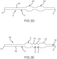
- the catheter 10 may comprise two or more retainer portions 20A as shown in Figure 3D for catheter 10', or have any suitable number of retainer portions along wall 12, wherein the plurality of retainer portions could be of different shapes and/or sizes.
- the catheter 10 can comprise a first retainer portion 20A and a second retainer portion 20A, wherein (if catheter 10 is being used in the lower urinary tract of a human male) both are positioned in the bulbar urethra when catheter 10 is positioned in a body.
- Retainer portions 20A would have respective lengths suitable for fitting into a body area such as the bulbar urethra, for their intended use.
- Figure 3E shows a catheter 10B that has a plurality of retainer portions 21, 21A, 21B, and 21C of different shapes and sizes.
- the retainer portions would have suitable shapes and sizes for fitting into one or more body areas, such as the bulbar urethra.
- any retainer portion can be comprised of solid material or include gas pockets.
- Each retainer portion should be atraumatic, and it preferably has a relatively soft, atraumatic surface.
- Retainer portion can be comprised of a flexible silicone and/or have a soft silicone surface coating.
- the retainer portion preferably has a durometer of any amount from: 1 to 40, or 5 to 30, or 10 to 25, or 15-25 Shore A.
- the retainer portion is preferably compressible.
- the retainer portion can comprise a material that compresses to pass through cross-sectional areas smaller than the maximum cross-sectional area of the retainer portion.
- the retainer portion When used in the lower urinary tract of a human male, the retainer portion should compress to at least a dimension so that it can be pushed or pulled through the maximum expanded dimension of urethra 2600, which could be about 6 mm to 12 mm, or about 10 mm. The retainer portion expands once it is no longer restricted. When used in the lower urinary tract of a human male, the retainer portion is compressed when it is pulled through the urethra 2600 and expands once it enters the bulbar urethra 2300.
- the retainer portion may be compressed to about 80%, 75%, 70%, 60%, 50%, 40%, 30%, 25%, 20%, 10%, or any amount from about 10% - 80% of the maximum cross-sectional area.
- the retainer portion 20 is compressed to any such amount when a total force is applied substantially equally to the outer surface of the retainer portion at the maximum cross-sectional area in an amount of 907.19g (2 lbs.), 1360.78g (3 lbs.), 1814.37g (4 lbs.), 2267.96g (5 lbs.), 2721.55g (6 lbs.), 3175.15g (7 lbs.), 3628.74g (8 lbs.), 4082.33g (9 lbs.), 4535.92g (10 lbs.), 4989.51g (11 lbs.), 5443.10g (12 lbs.), 5896.70g (13 lbs.), 6350.29g (14 lbs.), 6803.88g (15 lbs.), 7257.47g (16 lbs.), 7711.06g (17
- the retainer portion 20 can be physically compressed to 1/2 or less of the maximum cross-sectional area when subjected to a compressive force evenly applied along the outer surface of the cross-sectional area of an amount from: 1360.78g - 2267.96g (3-5 lbs.), or 907.19g - 1814.37g (2-4 lbs.), or 907.19g - 2721.55g (2-6 lbs.), or 1814.37g - 2721.55g (4-6 lbs.), or 2267.96g - 4535.92g (5-10 lbs.), or 3175.15g - 4535.92g (7-10 lbs.), or 2267.96g - 9979.03g (5-22 lbs.).
- the valve 100 is configured to restrict, or allow, fluid flow from the bladder 2000 (or other body part) out of the proximal end 16 of catheter 10.
- the valve 100 is located in lumen 14 between the proximal end 16 and the retainer portion 20, although the valve 100 can be positioned at any suitable location in the lumen 14, or at the distal end 18 or proximal end 16 of catheter 10, as long as the valve can open to allow, and close to prevent fluid flow out of proximal end 16.
- the valve 100 is a magnetic valve, and wireless controller 6000 (described below) can be placed on or near valve 100 from outside of the patient's body to operate valve 100.
- the valve 100 preferably comprises a cylindrical body.
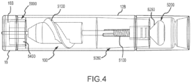
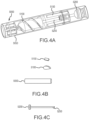
- the valve 100 includes a housing 5050, a screw portion 5100, a valve magnet 5150, a valve tip 5200, a spindle 5250, and an alignment tube 5300.
- the housing 5050 can comprise a cylindrical body.
- the screw portion 5100 can comprise a threaded body.
- the valve tip 5200 can be connected to the spindle 5250.
- the valve tip 5200 can be configured to open and close the valve.
- the valve tip 5200 can comprise a conical surface corresponding to a seating structure of the valve opening 5400.
- the screw portion 5100 can be movable inside the housing 5050.
- the housing 5050 and the screw portion 5100 can be in a threaded connection.
- the magnet can be connected to the screw portion 5100 and the spindle 5250.
- the valve 100 can open and close.
- the magnet 5150 can be moved by using an wireless controller 600 (described below) to open and close the valve 100, such as by spinning magnet 5150, in order to activate the valve 100 and facilitate and/or control fluid flow.
- the valve 100 and the wireless controller 6000 can be configured to allow the user to increase or decrease the flow rate of the urine from the bladder 2500 by the wireless controller 600 signaling the valve 100.
- valve 100 is a magnetic valve, as shown in this embodiment, when it is operated it pumps fluid, rather than simply allowing fluid to flow as a result of fluid pressure in the bladder 2500 or other body structure in which distal end 18 is positioned.
- the bladder 2500 as an example, by pumping fluid the bladder is more completely emptied, which can lead to relieving the bladder fewer times over a given period of time.
- the valve could be any structure that can be operated to (a) prevent the passage of fluid out of proximal end 16, and (b) allow fluid to flow past proximal end 16.
- a system according to the invention comprises a catheter 10 and a catheter mating device 1000, wherein the catheter mating device 1000 and catheter 10 are each configured to connect to one another so that catheter 10 can be moved by moving the catheter mating device 1000.
- the catheter mating device 1000 can be used to place the catheter 10 into a patient's body, and to remove the catheter 10 from the patient's body.
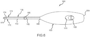
- the catheter mating device 1000 comprises a stem 1150 that includes: (a) a tube 1152 having an outer surface (or external wall) 1154 and a lumen 1162, (b) an inner cylinder 1160 having a distal end 1160A and a proximal end 1160B connected to a control 1520, and (c) a distal end 1170 with apparatus 1172.
- the apparatus 1172 is a structure that operates mechanically to connect the stem to the proximal end of the catheter, thus connecting the catheter mating device 100 to catheter 10.
- Apparatus 1172 has a first, retracted position, wherein it can fit inside of the proximal end 16 of tube 12, and a second, expanded position, wherein it engages proximal end 16 and connects catheter mating device 100 to catheter 10.
- the apparatus 1172 comprises tips 1174 that are configured to be positioned inside proximal end 16 (such as inside of engagement chamber 16B) when tips 1174 are in their first, retracted position and have a first distance between them (which may be zero distance because tips 1174 may touch when in the first, retracted position) as best seen in Figures 9-11 . Tips 1174 can be moved to their second, expanded position in which they have a second distance between them that is larger than the first distance. In the second, expanded position, tips 1174 engage the inner wall of engagement chamber 16B, which connects catheter 10 to catheter mating device 1000. Once engaged, the catheter 10 can be moved through the urethra 2600, as shown best in Figure 15 , by using the catheter mating device 1000 either to push and advance, or pull and retract, the catheter 10.
- the tips 1174 When in their second, expanded position, the tips 1174 (as measured when they are not restricted by a structure, such as the inner wall of mating chamber 16B or another structure), can have a maximum outer distance across them that is the same, or greater than, the diameter of mating chamber 16B (or other inner portion of catheter 10, such as lumen 14, because mating chamber 16B need not be used) in order for tips 1174 to create an interference fit against the inner wall of mating chamber 16B (or other structure).
- the tips 1174 can be comprised of any suitable material, such as a plastic, metal, or a thermoplastic elastomer.
- the tips 1174 at distal end 1170 form a tapered configuration such that they facilitate proper alignment of the tips 1774 and engagement chamber 16B so that tips 1774 can be received inside of chamber 16B (or other structure of catheter 10, such as lumen 14). Tips 1174 may have rounded end portions 1175 that assist in engaging proximal end 16.
- the catheter mating device 1000 in this embodiment comprises a cylinder 1160 positioned inside of outer tube 1152.
- the cylinder 1160 is operated to move from a retracted position to an extended position.
- the cylinder 1160 moves between the tips 1174 and pushes them open to their second, extended position.
- tips 1174 are in their first, retracted position.
- the cylinder 1160 may be comprised of any suitable material, such as ABS or PTFE, and preferably has a tapered distal end 1164.
- a user may operate the catheter mating device 1000 by moving the control 1520 to its second position, which move the apparatus 1172 to its second, expanded position, and by moving the control 1520 to its first position, in which the apparatus 1172 either moves to, or is moved to its first, retracted position.
- control 1520 is a slide switch directly or indirectly connected to cylinder 1160. When control 1520 is in its first position, the cylinder 1160 is in its first, retracted position. When control 1520 is moved to its second position, cylinder 1160 is moved to its second, extended position, wherein it moves between tips 1174 and pushes them open to their second, expanded position.
- tips 1174 are shown as the apparatus 1172, other structures that can be mechanically expanded (as opposed to expanding utilizing gas or liquids) may be used. For example, there may more than two tips that are expanded in the manner described herein. Or, the tips or other structures may be expanded in any suitable manner.
- the tube 1152 of the stem 1150 could function as an outer sheath, and the apparatus could be attached to the cylinder 1160.
- the apparatus could be a metal mesh tube. Such an apparatus would be in its first, retracted position when contained inside of the tube 1152. The tube would be connected to the control 1520 and pulled back to expose the apparatus when the control 1520 is moved proximally (i.e., away from the catheter 10).
- the cylinder 1160 including the apparatus could be connected to the control. In that case, a user could advance the cylinder 1160 and metal mesh tube out of the tube 1152, and the metal mesh tube would automatically expand to its second, expanded position.
- the stem could comprise an apparatus that is a flexible tube (comprised of rubber or flexible plastic) with one end of the tube connected to a first sleeve and another end connected to a second sleeve. The firs sleeve and second sleeve would be coaxial and at least one could move relative the other. A user could then manipulate one or both of the sleeves to compress the tube causing it to bulge, i.e., expand in the center, and engage the inner wall of the proximal end 16 (which could be engagement chamber 16B) of catheter 10.
- the stem 1150 in this embodiment has a length configured to enable a user to place catheter 10 in the urinary tract using the catheter mating device 1000.
- stem 1150 may have a lengths (a) greater than the length of the penile urethra of a patient, (b) less than or equal to the length as measured from the membranous portion to the urethral orifice of a patient, and/or (c) less than the length of the penile urethra of a patient.
- the stem 1150 is about 10 cm to 26 cm in length.
- Stem 1150 can include a fluid opening 1162 that is configured to allow fluid flow from the catheter 10 to pass through the lumen 1164 of stem 1150 and out of the proximal end 1152A of tube 1152, where the fluid can be collected or disposed, or pass through housing 1500 to be collected or disposed.
- the catheter retainer portion 1000 has a handle (or housing) 1500 at its proximal end.
- Housing 1500 may house a portion of the stem 1150 and/or cylinder 1160, and includes a control 1520.
- the housing 1500 is comprised of any suitable material such as PVC or other plastic.
- Housing 1500 has body portion 1500A, which can be formed of two connected portions 1550 and 1580 as shown in Figure 7 .
- Body portion 1500A has a distal end 1502, a proximal end 1504, and a cavity 1506.
- An opening 1510, which communicates with cavity 1506, is in surface 1588.
- a control 1520 is positioned in cavity 1506 and extends through opening 1510 where it can be accessed by a user.
- control 1520 is a slide switch that can be moved from a first (proximal) position to a second (distal position).
- Control 1520 has a ridge 1522 that can be pushed by a user's finger, a body portion 1524 that extends through opening 1510, and a base 1526 positioned in cavity 1506.
- Fasteners 1528 extend through apertures 1530 to retain control in housing 1500.
- cylinder 1160 is connected to control 1520.
- a user can move switch 1520 in a distal direction to push cylinder 1160 to its extended position, wherein the cylinder 1160 moves the apparatus to its second, expanded position.
- a user can move switch 1520 in a proximal direction, wherein the cylinder 1160 moves to its retracted position away from the apparatus 1172 and the apparatus moves to its first, retracted position.
- control 1520 could be any structure that can operate to directly or indirectly move the apparatus to its second, expanded position.
- the proximal end 1152A of tube 1152 is retained inside of cavity 1506. If fluid enters lumen (or passageway) 1164 it exits the proximal end 1152A, and can flow through housing 1500, where it exits opening 1504A at proximal end 1504. This allows for relatively easy collection or disposal of fluid from the body in which catheter 10 is positioned.
- the stem 1150 has a length of about 10 cm to 26 cm.
- the catheter 10 and the stem 1170 of catheter mating device 1000 are, respectively, constructed in a shape and of a material that is conducive for their intended use.
- the catheter 10 and stem 1170 may be constructed of any material or materials suitable for catheters used in the body (such as PVC, latex, silicone, polyurethane or any suitable blend of these materials).
- the catheter mating device 1000 and the catheter 10 can be carried in a sterilized pouch.
- a user may open the pouch comprising a catheter 10 and the catheter mating device 1000 and insert the catheter 10 into the lower urinary tract, and could use catheter mating device 1000 before inserting the catheter 10 into orifice 2700 of urethra 2600.
- Urine in the bladder can be voided when the user utilizes an external wireless controller 6000 (shown in Figures 2 and 5 ) to operate the valve 100 and allow urine to travel through the lumen 14, past proximal end 16, and out of catheter 10.
- the wireless controller 6000 can comprise an wireless controller magnet 6050, a power source 6100, an electronic circuitry 6150, and one or more inputs 6200, 6250.
- the one or more inputs 6200, 6250 can comprise a first input to open the valve 100 and a second input to close the valve 100.
- the wireless controller comprises two or more input modes, such as a close mode, an open mode, and an off mode.
- the valve 100 is closed (or off) when the wireless controller 6000 is in its close mode, and is open (or in operation) when the wireless controller is in its open mode.
- the valve 100 can remain closed or remain opened when the wireless controller 6000 is in its off mode.
- the circuitry 6150 can comprise software configured to automate the process of controlling fluid flow from bladder.
- a user can place the wireless controller 6000 near the valve 100, e.g., on the skin of the patient between the scrotum and the shaft of the penis. The user may press the input 6200 to operate the magnet 6050.
- the catheter 10D can include one or more sensors 2000 configured to transmit data from the patient's body.
- catheter 10' is the same as catheter 10, described above.
- any sensor used with a catheter according to the invention is referenced by numeral 2000.
- one or more sensors 2000 refers to a single sensor and a plurality of sensors.
- the data can comprise one or more of: fluid pressure of urine in the bladder and/or urethra, volume of fluid in the bladder, temperature of fluid in the bladder and/or urethra, acidity of fluid in the bladder and/or urethra, bacteria type and quantity of fluid in the bladder and/or urethra, chemical composition of fluid of fluid in the bladder and/or urethra, fluid flow during emptying of the bladder when valve 100 is open, or actuated.
- One or more sensors 2000 as described in this disclosure are of a type known to those skilled in the relevant art, although the claims are not limited to presently-known sensors.
- One or more sensors 2000 on or inside of catheter 10D would have basically consistent sensor location and extended sensors measurements within the body to better monitor patient conditions, without having sensors taken out of the body.
- the one or more sensors 2000 can be placed at any suitable location on catheter 10D.
- one or more sensors 2000 can be placed on or near the distal tip 18 of catheter 10D, in which case one or more sensors 2000 would be positioned in the bladder if catheter 10D is configured for use in the lower urinary tract of a human male.
- a catheter 10D could comprise different inner diameters can include a diameter in which a sensor 2000 would fit, such that the sensor is retained within lumen 14 without preventing fluid flow through the lumen.
- a sensor 2000 could be distal to openings 18A. The outer wall 12A of the tube 12 would then prevent sensor 2000 from contacting body tissue or fluid.
- One or more sensors 2000 may be positioned on or in retainer portion 20.
- one or more sensors 2000 can determine the pressure of urine within the bladder and send a signal to a processor that sends the information to a computing device, or the one or more sensors 2000 could send data directly to the computing device.
- the computing device which can be any device, such as a PC or other computer, cell phone, dedicated catheter device, the wireless controller, or the catheter mating device, can have software that determines whether and when fluid (such as urine) needs to be drained from the bladder. The computing device can notify the user in any manner to drain urine from his/her bladder.
- the one or more sensors 2000 can be used to determine when urine has been sufficiently drained from the bladder, such as by determining that the pressure level within the bladder has dropped below a certain level.
- the one or more sensors 2000 can include acoustics to determine the volume of urine in the bladder. Different types of sensors can be placed in or on the catheter 10 to determine metrics related to the health of areas of the body, such as bladder health.
- a sensor 2000 can be configured to detect the flow rate of urine through the valve 100.
- a catheter system 10D can comprise software configured to detect the flow rate of urine through the valve 100 by measuring the electric current draw of the valve motor by wireless controller 6000.
- the catheter system 10D can comprise an external computing device comprising a memory in wireless communication (either intermittently or continuously) with the electronic circuitry 6150 of wireless controller 6000 to record store and/or transmit data measured by one or more sensors 2000.
- one or more sensors 2000 can function without a power source. By constructing the sensor in a specific manner the external unit can observe changes in the resonant frequency characteristics.
- the data collected by one or more sensors 2000 can be stored, analyzed, and/or transmitted via software resident on a device outside of the body in which one or more sensors 2000 is positioned.
- the software may utilize machine-learning algorithms to predict and interpret the measurements.
- the sensor can be configured to change its mechanical properties (e.g. size or shape) based on pressure changes inside the bladder.
- the user can use an external device to detect changes in mechanical properties of the sensor by, for example, sending and/or receiving magnetic or electronic signals.
- catheter 10E has lumen 14 as described herein, and a second lumen 14'. In all other respects, catheter 10E is the same as previously described catheter 10D.
- Second lumen 14' can house one or more antennas 2002 that communicate in any suitable manner with the one or more sensors 2000 and with one or more external devices, such as a transducer or external computer device.
- Antennas 2002 can send data from one or more sensors 2000 to one or more external devices and signals from one or more external devices to any of the one or more sensors 2000.
- Antennas 2100 can have a power source 2004.
- One, some, or all of the one or more sensors 2000 may be partially or totally in second lumen 14'.
- One or more sensors 2000 can utilize basic wireless transmission protocol to send data to a computing device. This can be accomplished utilizing to Bluetooth, 802.11 WiFi, SONAR, UltraSound, MedRadio, or other wireless communications protocols.
- the sensors can be configured to interface with CT, ultrasound, x-ray, and/or electronic data storage devices.
- One or more sensors 2000 can comprise parts configured to interface and/or communicate with different products.
- one or more sensors 2000 can be configured to interface with Amazon Echo ® or Google Home ® .
- One or more sensors 2000 could also be configured to interface with patient databases in hospitals or elsewhere.
- Information provided by a sensor 2000 may be formatted as desired. For example, analog data related to movement may be converted (using an analog to digital converter, for example) to a digital format, and subsequently formatted into a data packet including a data header followed by one or more data values.
- Any amount of data can be transmitted in any manner.
- data from one or more sensors 2000 can be transmitted to another device as the data is measured, or data can be stored (such as in a memory storage device) for a period of time before being transmitted to another device.
- a device may be out of range or otherwise unavailable to receive the data from one or more sensors 2000.
- the data can also be stored for any desired length of time, and/or until a particular event occurs.
- the data could be stored by one or more sensors 2000 until the catheter mating device 1000 is connected to catheter 10' or 10", or until wireless controller 6000 is operated.
- Data could also be transmitted by one or more sensors 2000 to any device, such as the wireless controller 6000, catheter mating device 1000, or a cell phone.
- the data could be transmitted to such a device when the device is within a given range of one or more sensors 2000 (and hence a given range of the antenna(s) 2002, if utilized).
- Data can also be deleted when a data record in a sensor 2000 exceeds a predetermined storage time, and/or the oldest data record is deleted first after a predetermined storage size limit has been reached.
- the catheter system 1000 can comprise a computing device external to the patient's body.
- the external computing device may comprise a memory wirelessly connected to the electronic circuitry 6150 to receive operational parameters of the lower urinary tract.
- the computing device can have a software which can be used to interpret data gathered the one or more sensors 2000.
- one or more sensors 2000 may be a pressure sensor and the computing device can analyze data pressure received from the sensor 2000 be used to alert a user about when the user's bladder is likely to contract and void.
Landscapes
- Health & Medical Sciences (AREA)
- Life Sciences & Earth Sciences (AREA)
- Engineering & Computer Science (AREA)
- Public Health (AREA)
- General Health & Medical Sciences (AREA)
- Veterinary Medicine (AREA)
- Animal Behavior & Ethology (AREA)
- Biomedical Technology (AREA)
- Heart & Thoracic Surgery (AREA)
- Biophysics (AREA)
- Medical Informatics (AREA)
- Molecular Biology (AREA)
- Surgery (AREA)
- Pathology (AREA)
- Physics & Mathematics (AREA)
- Urology & Nephrology (AREA)
- Hematology (AREA)
- Physiology (AREA)
- Anesthesiology (AREA)
- Pulmonology (AREA)
- Epidemiology (AREA)
- Computer Networks & Wireless Communication (AREA)
- Cardiology (AREA)
- Oral & Maxillofacial Surgery (AREA)
- Transplantation (AREA)
- Vascular Medicine (AREA)
- External Artificial Organs (AREA)
- Media Introduction/Drainage Providing Device (AREA)
Description
- This disclosure relates to a catheter system that can be used for bladder management, such as an extended-use catheter and devices that can connect to the extended use catheter in order to position it in a body and/or remove it from a body.
- Many people suffer from lower urinary tract dysfunction, also known as neurogenic bladder. Neurogenic bladder can be defined as impaired urinary function due to neurological injury or disease, such as spinal cord injury (SCI). Current methods for managing neurogenic bladder and other chronic urinary retention disorders are to drain the bladder using (a) intermittent catheterization (IC), or (b) indwelling Foley catheters. These methods, however, are associated with relatively high rates of urinary tract infection and genito-urinary (GU) injury, each of which diminishes a patient's quality of life. Furthermore, because some individuals with neurogenic bladder lack bladder sensation, and thus cannot accurately perceive bladder fullness, they are susceptible to bladder overfilling. This can result in urinary "accidents" and/or urinary reflux, and urinary reflux presents a risk of infection and tissue damage to the upper urinary tract.
- To avoid these problems, individuals with neurogenic bladder on an IC program commonly rely on a timed catheterization schedule. This approach is imprecise and may lead to catheterization more frequently than necessary, which can increase the risk of infection and GU injury. Therefore, it is desirable to provide an improved urinary prosthesis that helps to alleviate one or all of the preceding problems.
- Said problems are solved by means of a catheter system as defined in claim 1, while
US 2017/156838 A1 andWO 2016/118943 A2 disclose known catheter systems, each comprising some features of claim 1. For example,US2017/156838 discloses a catheter system comprising: a catheter comprising a tube with a proximal end with an opening in communication with a catheter lumen and provided with a valve, a catheter mating device comprising a stem with an apparatus having a first, retracted configuration and a second, expanded configuration and being configured to be received in the proximal end of the catheter in its first, retracted configuration, and being configured to engage the proximal end of the catheter when in its second, expanded configuration, wherein a housing is connected to the proximal end of the stem. - The present disclosure relates to catheter systems for extended-use bladder management and controlling urinary function for humans or other animals. The disclosed systems may be used for fluid flow control for other bodily organs as well, such as kidneys, or draining abscesses or fluids from a body, and the description herein for bladder-control use is not limiting.
- Disclosed is an extended-use catheter configured for being retained inside of the body. The catheter can be used, for example, in the human male urinary tract. When in use, it is preferably positioned fully inside of, and retained in, the urethra and bladder. In one embodiment, the catheter comprises an elongated tube having a wall with an outer surface, and a lumen through which fluid, such as urine, can pass. Positioned on, or formed as part of, the tube wall is a retainer portion with a cross-sectional area greater than the cross-sectional area of the outer surface of the tube wall. When the catheter is properly positioned in the urinary tract, the retainer portion is positioned in the bulbar urethra, where it aids in the proper positioning of the catheter and helps prevent the catheter from inadvertently moving forward or backward.
- A catheter according to this disclosure could be periodically inserted, removed, and replaced by the user without medical assistance or the aid of another individual, which is convenient and saves time and medical expense. Such a catheter could remain in the body for days or weeks without being removed, which alleviates the problem of catheterization multiple times per day.
- The catheter includes a valve, wherein the valve can be operated to: (a) allow fluid to exit the proximal end of the catheter, where it can exit the body, or (b) prevent the flow of fluid out of the proximal end of the catheter. The valve is most preferably a magnetic valve controlled from outside of the body using a wireless controller that generates a wireless signal to the valve to open or close.
- A catheter mating device configured to engage and move the catheter is also disclosed and has a distal end and a proximal end. The distal end is configured to connect to the proximal end of the catheter, and includes an apparatus moveable between: (a) a first position, wherein the apparatus is retracted, and (b) a second position, wherein the apparatus is expanded. When in the first position, the apparatus is configured to fit into the lumen (or a mating chamber of the catheter) at the proximal end of the catheter. Once placed in the lumen, the apparatus can be moved to its second position, wherein the apparatus expands until it presses against and engages the wall of the lumen (or inner wall of the mating chamber). That connects the catheter mating device to the catheter, and the catheter can then be pushed into, or removed from a body structure, such as a bladder and urethra by, respectively, pushing or pulling the catheter mating device. Thus, the catheter mating device can be used to: (a) accurately place the catheter inside of a body, and/or (b) remove the catheter from a body.
- The catheter may be configured to include one or more sensors, which may be on, inside of, or embedded in material forming the catheter, or partially or entirely within the lumen. The one or more sensors can be at any suitable location on the catheter, such as at a position where they are positioned in the bladder when the catheter is properly positioned in the lower urinary tract of a human male. The one or more sensors could collect any relevant data, such as fluid pressure in the bladder, pH level of fluid, volume of urine in the bladder, and/or amount of blood or bacteria in urine. The one or more sensors could communicate with other devices, such as CT scanners, ultrasound devices, x-ray machines, electronic data storage devices, computers, cell phones, the wireless controller, the catheter mating device and/or sensors placed in toilets. The data collected by the sensors could be stored, analyzed and/or transmitted by a device including software configured for these functions.
- Because the catheter can remain in the body for long periods, a sensor on the catheter can gather and send data over the entire period the catheter is in the body, as opposed to gathering data only at a specific time, such as when a patent is at a doctor's office or hospital.
- A catheter according to aspects of the invention could also include one or more antennas to communicate with the one or more sensors, and transmit data collected by the one or more sensors. The catheter could have a second lumen that includes one or more antennas and one or more catheters.
- As used herein, the term "user" means any person able to insert and/or remove a catheter as disclosed herein, and includes a patient, doctor, caregiver, and nurse. "Patient" means a person that uses a catheter as disclosed herein in his/her body. "Lower urinary tract" refers collectively to the urinary bladder and urethra. "Extended use" means a catheter that can be used without having to remove it from the body more than once every two days or longer.
-
-
Figure 1 is a side view of an exemplary catheter, with an open view at its proximal end. -
Figure 1A is a cross-sectional view of the tube of the catheter ofFigure 1 taken alonglines 1A-1A. -
Figure 2 shows the catheter ofFigure 1 positioned in the lower urinary tract of a human male. -
Figure 3A is a side view of an exemplary embodiment of a catheter retainer portion according to aspects of the invention. -
Figure 3B is a cross-sectional view of the catheter retainer portion ofFigure 3A taken alonglines 3A-3A. -
Figure 3C is a side, perspective view of an exemplary embodiment of a catheter retainer portion according to aspects of the invention. -
Figure 3D is a side, perspective view of an alternative exemplary embodiment of a catheter according to aspects of the invention that has a plurality of retainer portions. -
Figure 3E is a side, perspective view of an exemplary embodiment of a catheter according to aspects of the invention that has a plurality of retainer portions -
Figure 4 is a close-up, open view of the proximal end of the catheter ofFigure 1 showing a valve. -
Figures 4A-4C show the valve ofFigure 4 and components of the valve. -
Figure 5 is an exemplary embodiment of a wireless valve wireless controller. -
Figure 6 is a top view of an exemplary catheter mating device. -
Figure 7 is an exploded view of the catheter mating device ofFigure 6 . -
Figure 8 is a side, perspective, close-up view of the distal end of the stem of the catheter mating device ofFigure 6 . -
Figures 8A and 8B are front views of the distal end of the stem of the catheter mating device ofFigure 6 . -
Figures 8C and 8D are partial, side views of the distal end of the stem of the catheter mating device ofFigure 6 . -
Figure 9 is a top view of the catheter mating device ofFigure 6 (with the apparatus in its first, retracted position) being aligned with the catheter ofFigure 1 . -
Figure 10 is another top view of catheter mating device ofFigure 6 (with the apparatus in its first, retracted position) being aligned with the catheter ofFigure 1 . -
Figure 11 is a side, open view of the catheter mating device ofFigure 6 (with the apparatus in its first, retracted position) with its distal end positioned in the lumen at the proximal end of the catheter ofFigure 1 . -
Figure 12 is a side view of an exemplary catheter that has one or more sensors, with an open view at its proximal end. -
Figure 13 is a side view of an exemplary catheter having two lumens, with an open view at its proximal end. -
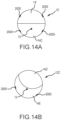
Figures 14A and 14B are cross-sectional views of exemplary catheters with two lumens. -
Figure 15 shows the catheter mating device ofFigure 6 (with the apparatus in its second, expanded position) engaged with the catheter ofFigure 1 . -
Figure 16 shows the catheter mating device ofFigure 6 being aligned with the catheter ofFigure 1 when the catheter is positioned in the lower urinary tract of a human male. - Turning now to the Figures, wherein the purpose is to describe preferred embodiments and not to limit the scope of the invention,
Figure 1 shows anexemplary catheter 10 according to aspects of the invention.Catheter 10 is an extended use catheter, and can be shaped and sized to be introduced into, and retained in, the lower urinary tract of a human male. As shown inFigure 2 ,catheter 10 can extend from the bladder 2050 to a portion of theurethra 2600 distal to the prostate and distal to the bulbar urethra.Catheter 10 as shown inFigure 2 extends past the prostate and the external urinary sphincter. In a female anatomy, the retainer portion is preferably positioned within the urethra, between the internal urethral orifice and the external urethral orifice. The retainer portion can then be positioned such that it is in the urethra between the meatus and the external urethral sphincter.Catheter 10 is preferably fully internal to the body once properly installed. - Turning to
Figures 1 and1A ,catheter 10 comprises atube 12 with awall 12A having anouter surface 12B, alumen 14 with alumen wall 14A, avalve 100, aretainer portion 20, aproximal end 16 possibly with aproximal tip 16A and anengagement chamber 16B, and adistal end 18 possibly withopenings 18A and adistal tip 18B. Thecatheter tube 12, which is shown in cross section inFigure 1A , preferably has a circular cross-sectional shape, but can be of any shape suitable for the intended use ofcatheter 10. When used in the lower urinary tract of a human male, as shown inFigure 2 ,tube 12 preferably has an outer diameter (as measured acrossouter surface 12B) ranging from about 1 French (0.3 mm) to 20 French (6.6 mm), which is approximately the same as or less than the maximum expanded dimension of theurethra 2600.Wall 12 can have a hardness of any amount from: about 30 Shore A to 55 Shore D, or about 30 Shore A, or about 30 to 50 Shore A, or about 20 to 50 Shore A, although any suitable hardness for the intended use ofcatheter 10 would suffice. -
Lumen 14 may have any suitable cross-sectional geometrical shape (e.g., circular (which is most preferred), oval, semi-circular, rectangular, triangular, trapezoidal, or crescent) and can have a cross-sectional surface area (which is the area inside oflumen wall 14A when viewed in cross section ) equivalent to the area of a 0.1 mm diameter circle to that of a 5.5 mm diameter circle. If the cross-sectional shape oflumen 14 iscircular lumen 14 preferably has a diameter of any amount from: 0.1 mm to 5.5 mm.Lumen 14 may also comprise different cross-sectional areas along its length. For example, the cross-sectional area of the lumen may be greater where thevalve 100 is positioned, and/or a greater cross-sectional area at theproximal end 16. Or, the lumen's cross-sectional area may be greater along its entire length distal tovalve 100. -
Tip 16A can have an outer diameter greater than the diameter of theouter wall 12B. For example,tip 16A may have a diameter of 0.5mm - 1 mm greater thanouter wall 12B. The purpose oftip 16A having a slightly larger diameter is so a user can locate it by touch (e.g., by pressing against the skin and feeling the ridge attip 16A) whentip 16A is positioned in the penile urethra. - An
engagement chamber 16B can be at or near theproximal end 16 of thecatheter 10. Theengagement chamber 16B can be located between theproximal tip 16A and thevalve 100, or extend fromproximal tip 16A tovalve 100 or a positionproximal valve 100. Theengagement chamber 16B includes a space configured to engage theapparatus 1172 as generally shown inFigures 9-11 and described below. Theengagement chamber 16B can have an annular, cylindrical shape, with a circular cross-section although any suitable shape may be used. As shown, theengagement chamber 16B has a circular cross-sectional shape with a diameter preferably form 0.1 mm to 5.5 mm. Theengagement chamber 16B may have a hardness greater than the hardness oftube 12. For example, the hardness may be of any hardness between 10 Shore A to 55 Shore D harder thantube engagement chamber 16B being harder thantube 12 is to bettersecure apparatus 1172 inengagement chamber 16B. It is not, however, required thatcatheter 10 have amating chamber 16B. For example,apparatus 1172 could engagelumen wall 14A or another structure. - As shown in
Figures 1 and2 ,distal end 18 andtip 18B are configured to enter the patient's body through theurethral orifice 2700, and into theurethra 2600 whencatheter 10 is positioned inside the lower urinary tract. As shown in this embodiment,distal tip 18B is tapered, rounded and closed. Thedistal tip 18B can comprise a material with hardness greater than the hardness ofwall 12A.Distal end 18 permits the inflow of bodily fluid, such as urine, from a bladder or other body part intolumen 14, which can be accomplished in any suitable manner. One or more (as shown, two)openings 18A permit bodily fluid, such as urine, to enterlumen 14. As shown,openings 18A are on opposite sides oftube 12, so if oneopening 18A is blocked because it is positioned against body tissue, theother opening 18A should still be unblocked. However, there need only be one opening, or there could be more than two openings, and the openings could be of any suitable size, configuration or location so they allow fluid, such as urine from the bladder, to enterlumen 14. - When
catheter 10 is positioned in the lower urinary tract of a human male, the one ormore openings 18A are positioned in thebladder 2500, as shown inFigure 2 . - The
retainer portion 20 is positioned in thebulbar urethra 2300 whencatheter 10 is properly positioned in the lower urinary tract of a human male.Retainer portion 20 is configured to prevent the inadvertent migration ofcatheter 10 either forward or backward oncecatheter 10 is properly positioned in the body. If positioned in the bulbar urethra, theretainer portion 20 is blocked by the external sphincter to prevent inadvertent retrograde migration, and blocked by the penile portion of theurethra 2600 to prevent inadvertent ante grade migration. When sufficient pulling or pushing force is applied tocatheter 10,retainer portion 20 compresses so that it can pass through theurethra 2600 whencatheter 10 is being removed from, or being placed in, the lower urinary tract. -
Retainer portion 20 is preferably formed: (a) over or as part ofwall 12A oftube 12, or (b) as a separate part that has a passage, such aspassage 28 shown inFigure 3B orpassage 8430 shown inFigure 3C , wherein part oftube 12 is positioned snuggly in the passage. Eachpassage tube 12 and enableretainer portion 20 to fit snuggly ontube 12.Retainer portion 20 can comprise ribs, dimples, staples, or other structures on its outer surface to help retain it in the bulbar urethra or other body area. - As best seen in
Figures 1 and3A , theretainer portion 20 can comprise atop surface 22, proximaltapered surface 24, and a distal taperedsurface 26. The proximaltapered surface 24 can be tapered from thetop surface 22 to about theouter surface 12B oftube 12. The distal taperedsurface 26 can be tapered from thetop surface 22 to about theouter surface 12A oftube 12. The retainer portion has a length as measured along the longitudinal axis X ofcatheter 10. In one embodiment theretainer portion 20 has a total length of any amount from about: 1 cm to 10 cm, or 2 cm to 8 cm, or 3 cm to 7 cm, or 4 cm to 6 cm, andtop surface 22 has a length of any amount from about: 1 cm to 10 cm, or about 10%, about 20%, about 30%, or about 40%, or about 50%, or about 60%, or about 70%, or about 80%, or about 90%, or about 95%, or any amount from about 5% to 95%, of the total length ofretainer portion 20. - In an embodiment suitable for use in the lower urinary tract of a human male, the maximum cross-sectional area as measured inside of surface 22 (and including the cross-sectional area of passage 28) or surface 8410 (and including the cross-sectional area of passage 8430) is: (a) greater than the cross-sectional area of the external sphincter, (b) greater than the cross-sectional area of the
penile urethra 2600, and (c) smaller than the cross-sectional dimension of thebulbar urethra 2300. The maximum cross-sectional area (as measured whenretainer portion 20 is not being compressed) of theretainer portion 20 is 1.5 to two times larger, three times as large, four times as large, five times as large, six times as large, seven times as large, eight times as large, nine times as large, ten times as large, or any amount from at least 1.5 to ten times as large, as the cross-sectional area measured inside theouter surface 12B oftube 12. The maximum cross-sectional area (as measured whenretainer portion 20 is not being compressed) may be any amount from: (24 mm)2π to (25 mm)2π, (4 mm)2π to (25 mm)2π, or (6mm)2π to (20 mm)2π, or (8 mm)2π to (16 mm)2π, or (10 mm)2π to (15 mm)2π, or (12 mm)2π to (15 mm)2π, or (5 mm)2π to (10 mm)2π. In one embodiment thetop surface 22 has a circular cross-sectional shape and has a diameter of any amount from: 5 mm to 10 mm, or 5 mm to 7 mm, or 4 mm to 8 mm, or 6 mm to 15 mm, or 8 mm to 15 mm, or 6 mm to 20 mm, or 8 mm to 22 mm. The diameter ofsurface 12B (which is the outer diameter of tube 12) can be about 2.0 mm to 6.0 mm, or 4.6 to 6.0 mm, or any amount from: 1.5 mm to 6.5 mm. -
Figure 3C shows alternate retainer portion 20' comprising one ormore mounds 8410 and one ormore grooves 8420 formed in itsouter surface 8410. The retainer portion 20' can comprise alternatinggrooves 8420 andmounds 8410. For example, the retainer portion 20' can comprise fourgrooves 8420 and fourmounds 8410 as shown inFigure 3C . The cross-sectional shape of the retainer portion could also symmetrical or asymmetrical, and be circular, cross-like, or any suitable shape for use withcatheter 10. - The
catheter 10 may comprise two ormore retainer portions 20A as shown inFigure 3D for catheter 10', or have any suitable number of retainer portions alongwall 12, wherein the plurality of retainer portions could be of different shapes and/or sizes. For example, thecatheter 10 can comprise afirst retainer portion 20A and asecond retainer portion 20A, wherein (ifcatheter 10 is being used in the lower urinary tract of a human male) both are positioned in the bulbar urethra whencatheter 10 is positioned in a body.Retainer portions 20A would have respective lengths suitable for fitting into a body area such as the bulbar urethra, for their intended use. -
Figure 3E shows acatheter 10B that has a plurality ofretainer portions - Regardless of the structure or number of the retainer portion(s) utilized, any retainer portion can be comprised of solid material or include gas pockets. Each retainer portion should be atraumatic, and it preferably has a relatively soft, atraumatic surface. Retainer portion can be comprised of a flexible silicone and/or have a soft silicone surface coating. The retainer portion preferably has a durometer of any amount from: 1 to 40, or 5 to 30, or 10 to 25, or 15-25 Shore A. The retainer portion is preferably compressible. For example, the retainer portion can comprise a material that compresses to pass through cross-sectional areas smaller than the maximum cross-sectional area of the retainer portion. When used in the lower urinary tract of a human male, the retainer portion should compress to at least a dimension so that it can be pushed or pulled through the maximum expanded dimension of
urethra 2600, which could be about 6 mm to 12 mm, or about 10 mm. The retainer portion expands once it is no longer restricted. When used in the lower urinary tract of a human male, the retainer portion is compressed when it is pulled through theurethra 2600 and expands once it enters thebulbar urethra 2300. - In some embodiments, the retainer portion may be compressed to about 80%, 75%, 70%, 60%, 50%, 40%, 30%, 25%, 20%, 10%, or any amount from about 10% - 80% of the maximum cross-sectional area. The
retainer portion 20 is compressed to any such amount when a total force is applied substantially equally to the outer surface of the retainer portion at the maximum cross-sectional area in an amount of 907.19g (2 lbs.), 1360.78g (3 lbs.), 1814.37g (4 lbs.), 2267.96g (5 lbs.), 2721.55g (6 lbs.), 3175.15g (7 lbs.), 3628.74g (8 lbs.), 4082.33g (9 lbs.), 4535.92g (10 lbs.), 4989.51g (11 lbs.), 5443.10g (12 lbs.), 5896.70g (13 lbs.), 6350.29g (14 lbs.), 6803.88g (15 lbs.), 7257.47g (16 lbs.), 7711.06g (17 lbs.), 8164.66g (18 lbs.), 8618.25g (19 lbs.), 9071.84g (20 lbs.), or any force within the range of: 453.59g - 4535.92g (1 - 10 lbs.), 907.19g - 9071.84g (2 - 20 lbs.), or 226.79g - 2267.96g (0.5 - 5.0 lbs.). Theretainer portion 20 can be physically compressed to 1/2 or less of the maximum cross-sectional area when subjected to a compressive force evenly applied along the outer surface of the cross-sectional area of an amount from: 1360.78g - 2267.96g (3-5 lbs.), or 907.19g - 1814.37g (2-4 lbs.), or 907.19g - 2721.55g (2-6 lbs.), or 1814.37g - 2721.55g (4-6 lbs.), or 2267.96g - 4535.92g (5-10 lbs.), or 3175.15g - 4535.92g (7-10 lbs.), or 2267.96g - 9979.03g (5-22 lbs.). - The
valve 100 is configured to restrict, or allow, fluid flow from the bladder 2000 (or other body part) out of theproximal end 16 ofcatheter 10. In the embodiment shown, thevalve 100 is located inlumen 14 between theproximal end 16 and theretainer portion 20, although thevalve 100 can be positioned at any suitable location in thelumen 14, or at thedistal end 18 orproximal end 16 ofcatheter 10, as long as the valve can open to allow, and close to prevent fluid flow out ofproximal end 16. As shown in this embodiment, thevalve 100 is a magnetic valve, and wireless controller 6000 (described below) can be placed on or nearvalve 100 from outside of the patient's body to operatevalve 100. - The
valve 100 preferably comprises a cylindrical body. As shown inFigure 4 , thevalve 100 includes ahousing 5050, ascrew portion 5100, avalve magnet 5150, avalve tip 5200, aspindle 5250, and an alignment tube 5300. Thehousing 5050 can comprise a cylindrical body. Thescrew portion 5100 can comprise a threaded body. Thevalve tip 5200 can be connected to thespindle 5250. Thevalve tip 5200 can be configured to open and close the valve. For example, thevalve tip 5200 can comprise a conical surface corresponding to a seating structure of thevalve opening 5400. - The
screw portion 5100 can be movable inside thehousing 5050. Thehousing 5050 and thescrew portion 5100 can be in a threaded connection. The magnet can be connected to thescrew portion 5100 and thespindle 5250. By moving themagnet 5150, thevalve 100 can open and close. For example, themagnet 5150 can be moved by using an wireless controller 600 (described below) to open and close thevalve 100, such as by spinningmagnet 5150, in order to activate thevalve 100 and facilitate and/or control fluid flow. Thevalve 100 and thewireless controller 6000 can be configured to allow the user to increase or decrease the flow rate of the urine from thebladder 2500 by thewireless controller 600 signaling thevalve 100. - If
valve 100 is a magnetic valve, as shown in this embodiment, when it is operated it pumps fluid, rather than simply allowing fluid to flow as a result of fluid pressure in thebladder 2500 or other body structure in whichdistal end 18 is positioned. Using thebladder 2500 as an example, by pumping fluid the bladder is more completely emptied, which can lead to relieving the bladder fewer times over a given period of time. Alternatively, the valve could be any structure that can be operated to (a) prevent the passage of fluid out ofproximal end 16, and (b) allow fluid to flow pastproximal end 16. - A system according to the invention comprises a
catheter 10 and acatheter mating device 1000, wherein thecatheter mating device 1000 andcatheter 10 are each configured to connect to one another so thatcatheter 10 can be moved by moving thecatheter mating device 1000. Thecatheter mating device 1000 can be used to place thecatheter 10 into a patient's body, and to remove thecatheter 10 from the patient's body. Thecatheter mating device 1000 comprises astem 1150 that includes: (a) atube 1152 having an outer surface (or external wall) 1154 and alumen 1162, (b) aninner cylinder 1160 having a distal end 1160A and a proximal end 1160B connected to acontrol 1520, and (c) adistal end 1170 withapparatus 1172. - The
apparatus 1172 is a structure that operates mechanically to connect the stem to the proximal end of the catheter, thus connecting thecatheter mating device 100 tocatheter 10.Apparatus 1172 has a first, retracted position, wherein it can fit inside of theproximal end 16 oftube 12, and a second, expanded position, wherein it engagesproximal end 16 and connectscatheter mating device 100 tocatheter 10. - In this embodiment, the
apparatus 1172 comprisestips 1174 that are configured to be positioned inside proximal end 16 (such as inside ofengagement chamber 16B) whentips 1174 are in their first, retracted position and have a first distance between them (which may be zero distance becausetips 1174 may touch when in the first, retracted position) as best seen inFigures 9-11 .Tips 1174 can be moved to their second, expanded position in which they have a second distance between them that is larger than the first distance. In the second, expanded position,tips 1174 engage the inner wall ofengagement chamber 16B, which connectscatheter 10 tocatheter mating device 1000. Once engaged, thecatheter 10 can be moved through theurethra 2600, as shown best inFigure 15 , by using thecatheter mating device 1000 either to push and advance, or pull and retract, thecatheter 10. - When in their second, expanded position, the tips 1174 (as measured when they are not restricted by a structure, such as the inner wall of
mating chamber 16B or another structure), can have a maximum outer distance across them that is the same, or greater than, the diameter ofmating chamber 16B (or other inner portion ofcatheter 10, such aslumen 14, becausemating chamber 16B need not be used) in order fortips 1174 to create an interference fit against the inner wall ofmating chamber 16B (or other structure). Thetips 1174 can be comprised of any suitable material, such as a plastic, metal, or a thermoplastic elastomer. - In some embodiments, the
tips 1174 atdistal end 1170 form a tapered configuration such that they facilitate proper alignment of the tips 1774 andengagement chamber 16B so that tips 1774 can be received inside ofchamber 16B (or other structure ofcatheter 10, such as lumen 14).Tips 1174 may have roundedend portions 1175 that assist in engagingproximal end 16. - The
catheter mating device 1000 in this embodiment comprises acylinder 1160 positioned inside ofouter tube 1152. Thecylinder 1160 is operated to move from a retracted position to an extended position. Whencylinder 1160 is in its extended position (as shown inFigures 8 ,8B , and8D ), thecylinder 1160 moves between thetips 1174 and pushes them open to their second, extended position. Whencylinder 1160 is in its retracted position (as shown inFigures 8 ,8A ,8C , and9-11 )tips 1174 are in their first, retracted position. Thecylinder 1160 may be comprised of any suitable material, such as ABS or PTFE, and preferably has a tapereddistal end 1164. - A user may operate the
catheter mating device 1000 by moving thecontrol 1520 to its second position, which move theapparatus 1172 to its second, expanded position, and by moving thecontrol 1520 to its first position, in which theapparatus 1172 either moves to, or is moved to its first, retracted position. In the embodiment shown,control 1520 is a slide switch directly or indirectly connected tocylinder 1160. Whencontrol 1520 is in its first position, thecylinder 1160 is in its first, retracted position. Whencontrol 1520 is moved to its second position,cylinder 1160 is moved to its second, extended position, wherein it moves betweentips 1174 and pushes them open to their second, expanded position. - Although
tips 1174 are shown as theapparatus 1172, other structures that can be mechanically expanded (as opposed to expanding utilizing gas or liquids) may be used. For example, there may more than two tips that are expanded in the manner described herein. Or, the tips or other structures may be expanded in any suitable manner. Alternatively, thetube 1152 of thestem 1150 could function as an outer sheath, and the apparatus could be attached to thecylinder 1160. In that example, the apparatus could be a metal mesh tube. Such an apparatus would be in its first, retracted position when contained inside of thetube 1152. The tube would be connected to thecontrol 1520 and pulled back to expose the apparatus when thecontrol 1520 is moved proximally (i.e., away from the catheter 10). That would permit the metal-mesh tube to automatically expand to its second, expanded position to engageproximal end 16. Or, utilizing the same structure, thecylinder 1160 including the apparatus could be connected to the control. In that case, a user could advance thecylinder 1160 and metal mesh tube out of thetube 1152, and the metal mesh tube would automatically expand to its second, expanded position. Alternatively, the stem could comprise an apparatus that is a flexible tube (comprised of rubber or flexible plastic) with one end of the tube connected to a first sleeve and another end connected to a second sleeve. The firs sleeve and second sleeve would be coaxial and at least one could move relative the other. A user could then manipulate one or both of the sleeves to compress the tube causing it to bulge, i.e., expand in the center, and engage the inner wall of the proximal end 16 (which could beengagement chamber 16B) ofcatheter 10. - The
stem 1150 in this embodiment has a length configured to enable a user to placecatheter 10 in the urinary tract using thecatheter mating device 1000. For example, in thisembodiment stem 1150 may have a lengths (a) greater than the length of the penile urethra of a patient, (b) less than or equal to the length as measured from the membranous portion to the urethral orifice of a patient, and/or (c) less than the length of the penile urethra of a patient. In some embodiments, thestem 1150 is about 10 cm to 26 cm in length.Stem 1150 can include afluid opening 1162 that is configured to allow fluid flow from thecatheter 10 to pass through thelumen 1164 ofstem 1150 and out of the proximal end 1152A oftube 1152, where the fluid can be collected or disposed, or pass throughhousing 1500 to be collected or disposed. - The
catheter retainer portion 1000 has a handle (or housing) 1500 at its proximal end.Housing 1500 may house a portion of thestem 1150 and/orcylinder 1160, and includes acontrol 1520. Thehousing 1500 is comprised of any suitable material such as PVC or other plastic.Housing 1500 has body portion 1500A, which can be formed of twoconnected portions 1550 and 1580 as shown inFigure 7 . Body portion 1500A has adistal end 1502, aproximal end 1504, and acavity 1506. Anopening 1510, which communicates withcavity 1506, is insurface 1588. Acontrol 1520 is positioned incavity 1506 and extends throughopening 1510 where it can be accessed by a user. - As shown,
control 1520 is a slide switch that can be moved from a first (proximal) position to a second (distal position).Control 1520 has aridge 1522 that can be pushed by a user's finger, abody portion 1524 that extends throughopening 1510, and abase 1526 positioned incavity 1506.Fasteners 1528 extend throughapertures 1530 to retain control inhousing 1500. - In the embodiment shown,
cylinder 1160 is connected to control 1520. A user can moveswitch 1520 in a distal direction to pushcylinder 1160 to its extended position, wherein thecylinder 1160 moves the apparatus to its second, expanded position. A user can moveswitch 1520 in a proximal direction, wherein thecylinder 1160 moves to its retracted position away from theapparatus 1172 and the apparatus moves to its first, retracted position. Although a manual slide switch is described herein,control 1520 could be any structure that can operate to directly or indirectly move the apparatus to its second, expanded position. - The proximal end 1152A of
tube 1152 is retained inside ofcavity 1506. If fluid enters lumen (or passageway) 1164 it exits the proximal end 1152A, and can flow throughhousing 1500, where it exits opening 1504A atproximal end 1504. This allows for relatively easy collection or disposal of fluid from the body in whichcatheter 10 is positioned. In one embodiment, thestem 1150 has a length of about 10 cm to 26 cm. - The
catheter 10 and thestem 1170 ofcatheter mating device 1000 are, respectively, constructed in a shape and of a material that is conducive for their intended use. For example, thecatheter 10 andstem 1170 may be constructed of any material or materials suitable for catheters used in the body (such as PVC, latex, silicone, polyurethane or any suitable blend of these materials). - The
catheter mating device 1000 and thecatheter 10 can be carried in a sterilized pouch. A user may open the pouch comprising acatheter 10 and thecatheter mating device 1000 and insert thecatheter 10 into the lower urinary tract, and could usecatheter mating device 1000 before inserting thecatheter 10 intoorifice 2700 ofurethra 2600. - Urine in the bladder (or fluid from another area in the body) can be voided when the user utilizes an external wireless controller 6000 (shown in
Figures 2 and5 ) to operate thevalve 100 and allow urine to travel through thelumen 14, pastproximal end 16, and out ofcatheter 10. As shown inFigure 5 , thewireless controller 6000 can comprise anwireless controller magnet 6050, a power source 6100, an electronic circuitry 6150, and one or more inputs 6200, 6250. In some embodiments, the one or more inputs 6200, 6250 can comprise a first input to open thevalve 100 and a second input to close thevalve 100. The wireless controller comprises two or more input modes, such as a close mode, an open mode, and an off mode. Thevalve 100 is closed (or off) when thewireless controller 6000 is in its close mode, and is open (or in operation) when the wireless controller is in its open mode. Thevalve 100 can remain closed or remain opened when thewireless controller 6000 is in its off mode. In some embodiments, the circuitry 6150 can comprise software configured to automate the process of controlling fluid flow from bladder. A user can place thewireless controller 6000 near thevalve 100, e.g., on the skin of the patient between the scrotum and the shaft of the penis. The user may press the input 6200 to operate themagnet 6050. - As shown in
Figure 12 , the catheter 10D can include one ormore sensors 2000 configured to transmit data from the patient's body. In all other respects, catheter 10' is the same ascatheter 10, described above. As used herein, any sensor used with a catheter according to the invention is referenced by numeral 2000. Thus, one ormore sensors 2000 refers to a single sensor and a plurality of sensors. The data can comprise one or more of: fluid pressure of urine in the bladder and/or urethra, volume of fluid in the bladder, temperature of fluid in the bladder and/or urethra, acidity of fluid in the bladder and/or urethra, bacteria type and quantity of fluid in the bladder and/or urethra, chemical composition of fluid of fluid in the bladder and/or urethra, fluid flow during emptying of the bladder whenvalve 100 is open, or actuated. One ormore sensors 2000 as described in this disclosure are of a type known to those skilled in the relevant art, although the claims are not limited to presently-known sensors. One ormore sensors 2000 on or inside of catheter 10D would have basically consistent sensor location and extended sensors measurements within the body to better monitor patient conditions, without having sensors taken out of the body. - The one or
more sensors 2000 can be placed at any suitable location on catheter 10D. For example, one ormore sensors 2000 can be placed on or near thedistal tip 18 of catheter 10D, in which case one ormore sensors 2000 would be positioned in the bladder if catheter 10D is configured for use in the lower urinary tract of a human male. A catheter 10D could comprise different inner diameters can include a diameter in which asensor 2000 would fit, such that the sensor is retained withinlumen 14 without preventing fluid flow through the lumen. For example, asensor 2000 could be distal toopenings 18A. Theouter wall 12A of thetube 12 would then preventsensor 2000 from contacting body tissue or fluid. One ormore sensors 2000 may be positioned on or inretainer portion 20. - In one embodiment, one or
more sensors 2000 can determine the pressure of urine within the bladder and send a signal to a processor that sends the information to a computing device, or the one ormore sensors 2000 could send data directly to the computing device. The computing device, which can be any device, such as a PC or other computer, cell phone, dedicated catheter device, the wireless controller, or the catheter mating device, can have software that determines whether and when fluid (such as urine) needs to be drained from the bladder. The computing device can notify the user in any manner to drain urine from his/her bladder. In some embodiments, the one ormore sensors 2000 can be used to determine when urine has been sufficiently drained from the bladder, such as by determining that the pressure level within the bladder has dropped below a certain level. This information can be used to close thevalve 100 and halt the flow of urine from leaving the bladder. In some embodiments, the one ormore sensors 2000 can include acoustics to determine the volume of urine in the bladder. Different types of sensors can be placed in or on thecatheter 10 to determine metrics related to the health of areas of the body, such as bladder health. - In some embodiments, a
sensor 2000 can be configured to detect the flow rate of urine through thevalve 100. For example, a catheter system 10D can comprise software configured to detect the flow rate of urine through thevalve 100 by measuring the electric current draw of the valve motor bywireless controller 6000. The catheter system 10D can comprise an external computing device comprising a memory in wireless communication (either intermittently or continuously) with the electronic circuitry 6150 ofwireless controller 6000 to record store and/or transmit data measured by one ormore sensors 2000. - In some embodiments, one or
more sensors 2000 can function without a power source. By constructing the sensor in a specific manner the external unit can observe changes in the resonant frequency characteristics. - The data collected by one or
more sensors 2000 can be stored, analyzed, and/or transmitted via software resident on a device outside of the body in which one ormore sensors 2000 is positioned. The software may utilize machine-learning algorithms to predict and interpret the measurements. - The sensor can be configured to change its mechanical properties (e.g. size or shape) based on pressure changes inside the bladder. The user can use an external device to detect changes in mechanical properties of the sensor by, for example, sending and/or receiving magnetic or electronic signals.
- In another embodiment shown in
Figure 13 ,catheter 10E haslumen 14 as described herein, and a second lumen 14'. In all other respects,catheter 10E is the same as previously described catheter 10D. Second lumen 14' can house one or more antennas 2002 that communicate in any suitable manner with the one ormore sensors 2000 and with one or more external devices, such as a transducer or external computer device. Antennas 2002 can send data from one ormore sensors 2000 to one or more external devices and signals from one or more external devices to any of the one ormore sensors 2000. Antennas 2100 can have a power source 2004. One, some, or all of the one ormore sensors 2000 may be partially or totally in second lumen 14'. - One or
more sensors 2000 can utilize basic wireless transmission protocol to send data to a computing device. This can be accomplished utilizing to Bluetooth, 802.11 WiFi, SONAR, UltraSound, MedRadio, or other wireless communications protocols. For example, the sensors can be configured to interface with CT, ultrasound, x-ray, and/or electronic data storage devices. - One or
more sensors 2000 can comprise parts configured to interface and/or communicate with different products. For example, one ormore sensors 2000 can be configured to interface with Amazon Echo ® or Google Home ®. One ormore sensors 2000 could also be configured to interface with patient databases in hospitals or elsewhere. Information provided by asensor 2000 may be formatted as desired. For example, analog data related to movement may be converted (using an analog to digital converter, for example) to a digital format, and subsequently formatted into a data packet including a data header followed by one or more data values. - Any amount of data can be transmitted in any manner. For example, data from one or
more sensors 2000 can be transmitted to another device as the data is measured, or data can be stored (such as in a memory storage device) for a period of time before being transmitted to another device. In some cases, for example, it may be more efficient to transmit blocks of data at once rather than initiating communication with another device each time data is available. In other cases, a device may be out of range or otherwise unavailable to receive the data from one ormore sensors 2000. The data can also be stored for any desired length of time, and/or until a particular event occurs. For example, the data could be stored by one ormore sensors 2000 until thecatheter mating device 1000 is connected tocatheter 10' or 10", or untilwireless controller 6000 is operated. Data could also be transmitted by one ormore sensors 2000 to any device, such as thewireless controller 6000,catheter mating device 1000, or a cell phone. The data could be transmitted to such a device when the device is within a given range of one or more sensors 2000 (and hence a given range of the antenna(s) 2002, if utilized). - Data can also be deleted when a data record in a
sensor 2000 exceeds a predetermined storage time, and/or the oldest data record is deleted first after a predetermined storage size limit has been reached. - The
catheter system 1000 can comprise a computing device external to the patient's body. The external computing device may comprise a memory wirelessly connected to the electronic circuitry 6150 to receive operational parameters of the lower urinary tract. In some embodiments, the computing device can have a software which can be used to interpret data gathered the one ormore sensors 2000. For example, one ormore sensors 2000 may be a pressure sensor and the computing device can analyze data pressure received from thesensor 2000 be used to alert a user about when the user's bladder is likely to contract and void.
Claims (13)
- A catheter system comprising:(a) a catheter (10) comprising (i) a tube, the tube (12) having (A) a wall (12A) with an outer surface (12B), the outer surface (12B) having a first cross-sectional area, (B) a lumen (14), (C) a distal end (18) with one or more openings in communication with the lumen (14), and (D) a proximal end (16) with an opening in communication with the lumen (14), (ii) a valve (100) that is operated to be in (A) a closed configuration, wherein fluid does not flow out of the proximal end (16), or (B) an open configuration in which fluid does flow out of the proximal end (16); and (iii) a retainer portion (20) between the distal end (18) and the proximal end (16), the retainer portion (20) having a maximum cross-sectional area at least 1.5 to 10 times as large as the first cross-sectional area;(b) a catheter mating device (1000) comprising: a stem (1150) having a proximal end (1160B) and a distal end (1160A); wherein the distal end (1160A) includes an apparatus (1172) having (i) a first, retracted configuration, and (ii) a second, expanded configuration; the apparatus (1172) being configured to be received in the proximal end (16) of the catheter when in its first, retracted configuration, and configured to engage the proximal end (16) of the catheter when in its second, expanded configuration; and(c) a housing (1500) connected to the proximal end (1160B) of the stem (1150), wherein the housing (1500) includes a control (1520) having a first position and a second position, and the apparatus (1172) is in its first, retracted position when the control (1520) is in its first position, and the apparatus (1172) is in its second, extended position when the control (1520) is in its second position, wherein the apparatus (1172) comprises a plurality of tips (1174) moveable from the first, retracted position to the second, extended position.
- The catheter system of claim 1, wherein the retainer portion (20) has a maximum cross-sectional area that is 1.5-4 times larger than the first cross-sectional area.
- The catheter system of claim 1 or 2, wherein the retainer portion (20) has a length and the maximum cross-sectional area is at a center of the length.
- The catheter system of claim 1, 2, or 3, wherein the maximum cross-sectional area is an area from: (4 mm)2π to (25 mm)2π.
- The catheter system of claim 1, 2, or 3, wherein the retainer portion (20) is circular in cross-section at its maximum cross-sectional area, and has a diameter of 5 mm to 10 mm at the maximum cross-sectional area.
- The catheter system of claim 1, 2, or 3, wherein the retainer portion (20) has an outer surface and can be physically compressed to 1/2 or less of the maximum cross-sectional area when subjected to a compressive force evenly applied along the outer surface of the cross-sectional area of an amount from: 1360.78g - 2267.96g (3-5 lbs.), or 907.19g - 1814.37g (2-4 lbs.), or 907.19g - 2721.55g (2-6 lbs.), or 1814.37g - 2721.55g (4-6 lbs.), or 2267.96g - 4535.92g (5-10 lbs.), or 3175.15g - 4535.92g (7-10 lbs.), or 2267.96g - 9979.03g (5-22 lbs.).
- The catheter system of claim 1, 2, or 3, wherein the retainer portion (20) is configured to be compressed to have a maximum diameter of 0.3 mm to 8.0 mm when moved through a penile urethra and to have a maximum diameter of 4.0 mm to 15 mm when positioned in the bulbar urethra (2300).
- The catheter system of claim 1, 2, or 3, wherein the retainer portion (20) includes a passage (28, 8430) therethrough and part of the tube (12) is positioned in the passage (28, 8430).
- The catheter system of claim 1, 2, or 3 that further includes one or more sensors (2000) on or in the catheter (10).
- The catheter system of claim 9, wherein the one or more sensors (2000) are configured to be positioned in a bladder when the catheter (10) is positioned in a lower urinary tract of a human male.
- The catheter system of claim 10, wherein the one or more sensors (2000) are positioned at least partially in the lumen.
- The catheter system of claim 1, wherein the control (1520) is a slide button on an outside surface of the housing (1500), the slide button moveable between the first position of the control and the second position of the control (1520).
- The catheter system of claim 10 that further includes one or more antennas (2100), wherein the antennas (2100) are configured to transmit data received from the one or more sensors (2000).
Applications Claiming Priority (5)
| Application Number | Priority Date | Filing Date | Title |
|---|---|---|---|
| US15/721,096 US10743975B2 (en) | 2015-01-23 | 2017-09-29 | Urinary prosthesis systems |
| US15/785,405 US11065093B2 (en) | 2015-01-23 | 2017-10-16 | Catheter mating devices |
| US15/785,403 US11510765B2 (en) | 2015-01-23 | 2017-10-16 | Extended-use catheters |
| US15/785,398 US10751506B2 (en) | 2015-04-01 | 2017-10-16 | Catheters and catheter mating devices and systems |
| PCT/US2018/053806 WO2019068104A1 (en) | 2017-09-29 | 2018-10-01 | Indwelling catheter, catheter introducer mating device and system comprising both |
Publications (2)
| Publication Number | Publication Date |
|---|---|
| EP3687616A1 EP3687616A1 (en) | 2020-08-05 |
| EP3687616B1 true EP3687616B1 (en) | 2024-06-19 |
Family
ID=65902501
Family Applications (1)
| Application Number | Title | Priority Date | Filing Date |
|---|---|---|---|
| EP18792715.7A Active EP3687616B1 (en) | 2017-09-29 | 2018-10-01 | Indwelling catheter, catheter introducer mating device and system comprising both |
Country Status (5)
| Country | Link |
|---|---|
| EP (1) | EP3687616B1 (en) |
| AU (1) | AU2018342615A1 (en) |
| CA (1) | CA3079692A1 (en) |
| GB (4) | GB2606647B (en) |
| WO (1) | WO2019068104A1 (en) |
Families Citing this family (8)
| Publication number | Priority date | Publication date | Assignee | Title |
|---|---|---|---|---|
| US11510765B2 (en) | 2015-01-23 | 2022-11-29 | Spinal Singularity, Inc. | Extended-use catheters |
| US9775698B2 (en) | 2015-01-23 | 2017-10-03 | Spinal Singularity, Inc. | Urinary prosthesis systems |
| US11065093B2 (en) | 2015-01-23 | 2021-07-20 | Spinal Singularity, Inc. | Catheter mating devices |
| US10675435B2 (en) | 2015-04-01 | 2020-06-09 | Spinal Singularity, Inc. | Extended-use valved urinary catheter |
| US10751506B2 (en) | 2015-04-01 | 2020-08-25 | Spinal Singularity, Inc. | Catheters and catheter mating devices and systems |
| US11628271B2 (en) | 2019-06-10 | 2023-04-18 | Spinal Singularity, Inc. | Urinary catheter |
| US12569650B2 (en) | 2019-06-10 | 2026-03-10 | Uroflow Technology, Llc | Urinary catheter with retention features |
| WO2021183365A2 (en) * | 2020-03-11 | 2021-09-16 | C. R. Bard, Inc. | Pressure activated catheter |
Citations (2)
| Publication number | Priority date | Publication date | Assignee | Title |
|---|---|---|---|---|
| US4932938A (en) * | 1989-05-05 | 1990-06-12 | Medical Engineering Corporation | Urethral indwelling catheter with incontinence control |
| WO2017015351A2 (en) * | 2015-07-20 | 2017-01-26 | Strataca Systems, LLC | Ureteral and bladder catheters and methods for inducing negative pressure to increase renal perfusion |
Family Cites Families (2)
| Publication number | Priority date | Publication date | Assignee | Title |
|---|---|---|---|---|
| US9775698B2 (en) * | 2015-01-23 | 2017-10-03 | Spinal Singularity, Inc. | Urinary prosthesis systems |
| ES2945879T3 (en) * | 2015-01-23 | 2023-07-10 | Spinal Singularity Inc | Bladder control systems |
-
2018
- 2018-10-01 GB GB2208645.8A patent/GB2606647B/en active Active
- 2018-10-01 WO PCT/US2018/053806 patent/WO2019068104A1/en not_active Ceased
- 2018-10-01 CA CA3079692A patent/CA3079692A1/en active Pending
- 2018-10-01 GB GB2208648.2A patent/GB2606083B/en active Active
- 2018-10-01 AU AU2018342615A patent/AU2018342615A1/en not_active Abandoned
- 2018-10-01 GB GB2004799.9A patent/GB2581277B/en active Active
- 2018-10-01 EP EP18792715.7A patent/EP3687616B1/en active Active
- 2018-10-01 GB GB2208651.6A patent/GB2606084B/en active Active
Patent Citations (2)
| Publication number | Priority date | Publication date | Assignee | Title |
|---|---|---|---|---|
| US4932938A (en) * | 1989-05-05 | 1990-06-12 | Medical Engineering Corporation | Urethral indwelling catheter with incontinence control |
| WO2017015351A2 (en) * | 2015-07-20 | 2017-01-26 | Strataca Systems, LLC | Ureteral and bladder catheters and methods for inducing negative pressure to increase renal perfusion |
Also Published As
| Publication number | Publication date |
|---|---|
| GB202208651D0 (en) | 2022-07-27 |
| GB2606647B (en) | 2023-02-08 |
| CA3079692A1 (en) | 2019-04-04 |
| GB202004799D0 (en) | 2020-05-13 |
| EP3687616A1 (en) | 2020-08-05 |
| AU2018342615A1 (en) | 2020-04-09 |
| GB2606084A (en) | 2022-10-26 |
| GB202208648D0 (en) | 2022-07-27 |
| GB2606647A (en) | 2022-11-16 |
| GB2606084B (en) | 2023-01-18 |
| GB2581277B (en) | 2022-07-27 |
| GB202208645D0 (en) | 2022-07-27 |
| WO2019068104A1 (en) | 2019-04-04 |
| GB2606083B (en) | 2023-01-18 |
| GB2581277A (en) | 2020-08-12 |
| GB2606083A (en) | 2022-10-26 |
Similar Documents
| Publication | Publication Date | Title |
|---|---|---|
| US11938014B2 (en) | Catheter mating devices | |
| US11628271B2 (en) | Urinary catheter | |
| US10751506B2 (en) | Catheters and catheter mating devices and systems | |
| US11510765B2 (en) | Extended-use catheters | |
| US10743975B2 (en) | Urinary prosthesis systems | |
| AU2018342615A1 (en) | Indwelling catheter, catheter introducer mating device and system comprising both | |
| US12569650B2 (en) | Urinary catheter with retention features | |
| CN111263653B (en) | Urinary pump for promoting removal of urine from urethra | |
| US11229771B2 (en) | Percutaneous ureteral catheter | |
| US12465720B2 (en) | Extended-use valved urinary catheter | |
| US12226594B2 (en) | Percutaneous urinary catheter | |
| CA1109351A (en) | Urinary retention catheter | |
| EP3247309B1 (en) | Bladder management systems | |
| CN107648720B (en) | Built-in catheter | |
| US11865270B2 (en) | Bodily fluid management system | |
| WO2017015351A2 (en) | Ureteral and bladder catheters and methods for inducing negative pressure to increase renal perfusion | |
| EP3886960A1 (en) | Percutaneous urinary catheter | |
| WO2024019943A1 (en) | Urinary catheter with retention features | |
| CN120899255A (en) | Early warning method for preventing urinary retention and catheterization based on real-time pressure feedback |
Legal Events
| Date | Code | Title | Description |
|---|---|---|---|
| STAA | Information on the status of an ep patent application or granted ep patent |
Free format text: STATUS: UNKNOWN |
|
| STAA | Information on the status of an ep patent application or granted ep patent |
Free format text: STATUS: THE INTERNATIONAL PUBLICATION HAS BEEN MADE |
|
| PUAI | Public reference made under article 153(3) epc to a published international application that has entered the european phase |
Free format text: ORIGINAL CODE: 0009012 |
|
| STAA | Information on the status of an ep patent application or granted ep patent |
Free format text: STATUS: REQUEST FOR EXAMINATION WAS MADE |
|
| 17P | Request for examination filed |
Effective date: 20200331 |
|
| AK | Designated contracting states |
Kind code of ref document: A1 Designated state(s): AL AT BE BG CH CY CZ DE DK EE ES FI FR GB GR HR HU IE IS IT LI LT LU LV MC MK MT NL NO PL PT RO RS SE SI SK SM TR |
|
| AX | Request for extension of the european patent |
Extension state: BA ME |
|
| DAV | Request for validation of the european patent (deleted) | ||
| DAX | Request for extension of the european patent (deleted) | ||
| STAA | Information on the status of an ep patent application or granted ep patent |
Free format text: STATUS: EXAMINATION IS IN PROGRESS |
|
| 17Q | First examination report despatched |
Effective date: 20220317 |
|
| RIC1 | Information provided on ipc code assigned before grant |
Ipc: A61F 2/04 20130101ALI20231124BHEP Ipc: A61B 5/00 20060101ALI20231124BHEP Ipc: A61M 39/24 20060101ALI20231124BHEP Ipc: A61M 39/22 20060101ALI20231124BHEP Ipc: A61F 2/00 20060101ALI20231124BHEP Ipc: A61B 5/03 20060101ALI20231124BHEP Ipc: A61B 5/20 20060101ALI20231124BHEP Ipc: A61M 25/01 20060101ALI20231124BHEP Ipc: A61M 25/00 20060101AFI20231124BHEP |
|
| GRAP | Despatch of communication of intention to grant a patent |
Free format text: ORIGINAL CODE: EPIDOSNIGR1 |
|
| STAA | Information on the status of an ep patent application or granted ep patent |
Free format text: STATUS: GRANT OF PATENT IS INTENDED |
|
| INTG | Intention to grant announced |
Effective date: 20240111 |
|
| RAP3 | Party data changed (applicant data changed or rights of an application transferred) |
Owner name: SPINAL SINGULARITY, INC. |
|
| GRAS | Grant fee paid |
Free format text: ORIGINAL CODE: EPIDOSNIGR3 |
|
| GRAA | (expected) grant |
Free format text: ORIGINAL CODE: 0009210 |
|
| STAA | Information on the status of an ep patent application or granted ep patent |
Free format text: STATUS: THE PATENT HAS BEEN GRANTED |
|
| AK | Designated contracting states |
Kind code of ref document: B1 Designated state(s): AL AT BE BG CH CY CZ DE DK EE ES FI FR GB GR HR HU IE IS IT LI LT LU LV MC MK MT NL NO PL PT RO RS SE SI SK SM TR |
|
| REG | Reference to a national code |
Ref country code: GB Ref legal event code: FG4D |
|
| REG | Reference to a national code |
Ref country code: CH Ref legal event code: EP |
|
| REG | Reference to a national code |
Ref country code: DE Ref legal event code: R096 Ref document number: 602018070810 Country of ref document: DE |
|
| REG | Reference to a national code |
Ref country code: NL Ref legal event code: FP |
|
| PG25 | Lapsed in a contracting state [announced via postgrant information from national office to epo] |
Ref country code: BG Free format text: LAPSE BECAUSE OF FAILURE TO SUBMIT A TRANSLATION OF THE DESCRIPTION OR TO PAY THE FEE WITHIN THE PRESCRIBED TIME-LIMIT Effective date: 20240619 |
|
| PG25 | Lapsed in a contracting state [announced via postgrant information from national office to epo] |
Ref country code: HR Free format text: LAPSE BECAUSE OF FAILURE TO SUBMIT A TRANSLATION OF THE DESCRIPTION OR TO PAY THE FEE WITHIN THE PRESCRIBED TIME-LIMIT Effective date: 20240619 Ref country code: FI Free format text: LAPSE BECAUSE OF FAILURE TO SUBMIT A TRANSLATION OF THE DESCRIPTION OR TO PAY THE FEE WITHIN THE PRESCRIBED TIME-LIMIT Effective date: 20240619 |
|
| REG | Reference to a national code |
Ref country code: LT Ref legal event code: MG9D |
|
| PG25 | Lapsed in a contracting state [announced via postgrant information from national office to epo] |
Ref country code: GR Free format text: LAPSE BECAUSE OF FAILURE TO SUBMIT A TRANSLATION OF THE DESCRIPTION OR TO PAY THE FEE WITHIN THE PRESCRIBED TIME-LIMIT Effective date: 20240920 |
|
| PG25 | Lapsed in a contracting state [announced via postgrant information from national office to epo] |
Ref country code: LV Free format text: LAPSE BECAUSE OF FAILURE TO SUBMIT A TRANSLATION OF THE DESCRIPTION OR TO PAY THE FEE WITHIN THE PRESCRIBED TIME-LIMIT Effective date: 20240619 |
|
| PG25 | Lapsed in a contracting state [announced via postgrant information from national office to epo] |
Ref country code: NO Free format text: LAPSE BECAUSE OF FAILURE TO SUBMIT A TRANSLATION OF THE DESCRIPTION OR TO PAY THE FEE WITHIN THE PRESCRIBED TIME-LIMIT Effective date: 20240919 Ref country code: LV Free format text: LAPSE BECAUSE OF FAILURE TO SUBMIT A TRANSLATION OF THE DESCRIPTION OR TO PAY THE FEE WITHIN THE PRESCRIBED TIME-LIMIT Effective date: 20240619 Ref country code: HR Free format text: LAPSE BECAUSE OF FAILURE TO SUBMIT A TRANSLATION OF THE DESCRIPTION OR TO PAY THE FEE WITHIN THE PRESCRIBED TIME-LIMIT Effective date: 20240619 Ref country code: GR Free format text: LAPSE BECAUSE OF FAILURE TO SUBMIT A TRANSLATION OF THE DESCRIPTION OR TO PAY THE FEE WITHIN THE PRESCRIBED TIME-LIMIT Effective date: 20240920 Ref country code: FI Free format text: LAPSE BECAUSE OF FAILURE TO SUBMIT A TRANSLATION OF THE DESCRIPTION OR TO PAY THE FEE WITHIN THE PRESCRIBED TIME-LIMIT Effective date: 20240619 Ref country code: BG Free format text: LAPSE BECAUSE OF FAILURE TO SUBMIT A TRANSLATION OF THE DESCRIPTION OR TO PAY THE FEE WITHIN THE PRESCRIBED TIME-LIMIT Effective date: 20240619 Ref country code: RS Free format text: LAPSE BECAUSE OF FAILURE TO SUBMIT A TRANSLATION OF THE DESCRIPTION OR TO PAY THE FEE WITHIN THE PRESCRIBED TIME-LIMIT Effective date: 20240919 |
|
| PGFP | Annual fee paid to national office [announced via postgrant information from national office to epo] |
Ref country code: NL Payment date: 20241026 Year of fee payment: 7 |
|
| REG | Reference to a national code |
Ref country code: AT Ref legal event code: MK05 Ref document number: 1695528 Country of ref document: AT Kind code of ref document: T Effective date: 20240619 |
|
| RAP2 | Party data changed (patent owner data changed or rights of a patent transferred) |
Owner name: UROFLOW TECHNOLOGY, LLC. |
|
| PG25 | Lapsed in a contracting state [announced via postgrant information from national office to epo] |
Ref country code: PT Free format text: LAPSE BECAUSE OF FAILURE TO SUBMIT A TRANSLATION OF THE DESCRIPTION OR TO PAY THE FEE WITHIN THE PRESCRIBED TIME-LIMIT Effective date: 20241021 |
|
| PG25 | Lapsed in a contracting state [announced via postgrant information from national office to epo] |
Ref country code: PT Free format text: LAPSE BECAUSE OF FAILURE TO SUBMIT A TRANSLATION OF THE DESCRIPTION OR TO PAY THE FEE WITHIN THE PRESCRIBED TIME-LIMIT Effective date: 20241021 |
|
| PGFP | Annual fee paid to national office [announced via postgrant information from national office to epo] |
Ref country code: DE Payment date: 20241029 Year of fee payment: 7 |
|
| PG25 | Lapsed in a contracting state [announced via postgrant information from national office to epo] |
Ref country code: PL Free format text: LAPSE BECAUSE OF FAILURE TO SUBMIT A TRANSLATION OF THE DESCRIPTION OR TO PAY THE FEE WITHIN THE PRESCRIBED TIME-LIMIT Effective date: 20240619 |
|
| PG25 | Lapsed in a contracting state [announced via postgrant information from national office to epo] |
Ref country code: EE Free format text: LAPSE BECAUSE OF FAILURE TO SUBMIT A TRANSLATION OF THE DESCRIPTION OR TO PAY THE FEE WITHIN THE PRESCRIBED TIME-LIMIT Effective date: 20240619 |
|
| PG25 | Lapsed in a contracting state [announced via postgrant information from national office to epo] |
Ref country code: IS Free format text: LAPSE BECAUSE OF FAILURE TO SUBMIT A TRANSLATION OF THE DESCRIPTION OR TO PAY THE FEE WITHIN THE PRESCRIBED TIME-LIMIT Effective date: 20241019 Ref country code: AT Free format text: LAPSE BECAUSE OF FAILURE TO SUBMIT A TRANSLATION OF THE DESCRIPTION OR TO PAY THE FEE WITHIN THE PRESCRIBED TIME-LIMIT Effective date: 20240619 |
|
| PGFP | Annual fee paid to national office [announced via postgrant information from national office to epo] |
Ref country code: FR Payment date: 20241025 Year of fee payment: 7 |
|
| PG25 | Lapsed in a contracting state [announced via postgrant information from national office to epo] |
Ref country code: CZ Free format text: LAPSE BECAUSE OF FAILURE TO SUBMIT A TRANSLATION OF THE DESCRIPTION OR TO PAY THE FEE WITHIN THE PRESCRIBED TIME-LIMIT Effective date: 20240619 |
|
| PG25 | Lapsed in a contracting state [announced via postgrant information from national office to epo] |
Ref country code: RO Free format text: LAPSE BECAUSE OF FAILURE TO SUBMIT A TRANSLATION OF THE DESCRIPTION OR TO PAY THE FEE WITHIN THE PRESCRIBED TIME-LIMIT Effective date: 20240619 Ref country code: SK Free format text: LAPSE BECAUSE OF FAILURE TO SUBMIT A TRANSLATION OF THE DESCRIPTION OR TO PAY THE FEE WITHIN THE PRESCRIBED TIME-LIMIT Effective date: 20240619 |
|
| PG25 | Lapsed in a contracting state [announced via postgrant information from national office to epo] |
Ref country code: ES Free format text: LAPSE BECAUSE OF FAILURE TO SUBMIT A TRANSLATION OF THE DESCRIPTION OR TO PAY THE FEE WITHIN THE PRESCRIBED TIME-LIMIT Effective date: 20240619 Ref country code: SM Free format text: LAPSE BECAUSE OF FAILURE TO SUBMIT A TRANSLATION OF THE DESCRIPTION OR TO PAY THE FEE WITHIN THE PRESCRIBED TIME-LIMIT Effective date: 20240619 |
|
| PGFP | Annual fee paid to national office [announced via postgrant information from national office to epo] |
Ref country code: IT Payment date: 20241021 Year of fee payment: 7 |
|
| PG25 | Lapsed in a contracting state [announced via postgrant information from national office to epo] |
Ref country code: SM Free format text: LAPSE BECAUSE OF FAILURE TO SUBMIT A TRANSLATION OF THE DESCRIPTION OR TO PAY THE FEE WITHIN THE PRESCRIBED TIME-LIMIT Effective date: 20240619 Ref country code: SK Free format text: LAPSE BECAUSE OF FAILURE TO SUBMIT A TRANSLATION OF THE DESCRIPTION OR TO PAY THE FEE WITHIN THE PRESCRIBED TIME-LIMIT Effective date: 20240619 Ref country code: RO Free format text: LAPSE BECAUSE OF FAILURE TO SUBMIT A TRANSLATION OF THE DESCRIPTION OR TO PAY THE FEE WITHIN THE PRESCRIBED TIME-LIMIT Effective date: 20240619 Ref country code: PL Free format text: LAPSE BECAUSE OF FAILURE TO SUBMIT A TRANSLATION OF THE DESCRIPTION OR TO PAY THE FEE WITHIN THE PRESCRIBED TIME-LIMIT Effective date: 20240619 Ref country code: IS Free format text: LAPSE BECAUSE OF FAILURE TO SUBMIT A TRANSLATION OF THE DESCRIPTION OR TO PAY THE FEE WITHIN THE PRESCRIBED TIME-LIMIT Effective date: 20241019 Ref country code: ES Free format text: LAPSE BECAUSE OF FAILURE TO SUBMIT A TRANSLATION OF THE DESCRIPTION OR TO PAY THE FEE WITHIN THE PRESCRIBED TIME-LIMIT Effective date: 20240619 Ref country code: EE Free format text: LAPSE BECAUSE OF FAILURE TO SUBMIT A TRANSLATION OF THE DESCRIPTION OR TO PAY THE FEE WITHIN THE PRESCRIBED TIME-LIMIT Effective date: 20240619 Ref country code: CZ Free format text: LAPSE BECAUSE OF FAILURE TO SUBMIT A TRANSLATION OF THE DESCRIPTION OR TO PAY THE FEE WITHIN THE PRESCRIBED TIME-LIMIT Effective date: 20240619 Ref country code: AT Free format text: LAPSE BECAUSE OF FAILURE TO SUBMIT A TRANSLATION OF THE DESCRIPTION OR TO PAY THE FEE WITHIN THE PRESCRIBED TIME-LIMIT Effective date: 20240619 |
|
| REG | Reference to a national code |
Ref country code: DE Ref legal event code: R097 Ref document number: 602018070810 Country of ref document: DE |
|
| PG25 | Lapsed in a contracting state [announced via postgrant information from national office to epo] |
Ref country code: DK Free format text: LAPSE BECAUSE OF FAILURE TO SUBMIT A TRANSLATION OF THE DESCRIPTION OR TO PAY THE FEE WITHIN THE PRESCRIBED TIME-LIMIT Effective date: 20240619 |
|
| PLBE | No opposition filed within time limit |
Free format text: ORIGINAL CODE: 0009261 |
|
| STAA | Information on the status of an ep patent application or granted ep patent |
Free format text: STATUS: NO OPPOSITION FILED WITHIN TIME LIMIT |
|
| 26N | No opposition filed |
Effective date: 20250320 |
|
| REG | Reference to a national code |
Ref country code: CH Ref legal event code: PL |
|
| GBPC | Gb: european patent ceased through non-payment of renewal fee |
Effective date: 20241001 |
|
| PG25 | Lapsed in a contracting state [announced via postgrant information from national office to epo] |
Ref country code: MC Free format text: LAPSE BECAUSE OF FAILURE TO SUBMIT A TRANSLATION OF THE DESCRIPTION OR TO PAY THE FEE WITHIN THE PRESCRIBED TIME-LIMIT Effective date: 20240619 |
|
| PG25 | Lapsed in a contracting state [announced via postgrant information from national office to epo] |
Ref country code: GB Free format text: LAPSE BECAUSE OF NON-PAYMENT OF DUE FEES Effective date: 20241001 |
|
| PG25 | Lapsed in a contracting state [announced via postgrant information from national office to epo] |
Ref country code: BE Free format text: LAPSE BECAUSE OF NON-PAYMENT OF DUE FEES Effective date: 20241031 Ref country code: LU Free format text: LAPSE BECAUSE OF NON-PAYMENT OF DUE FEES Effective date: 20241001 |
|
| PG25 | Lapsed in a contracting state [announced via postgrant information from national office to epo] |
Ref country code: CH Free format text: LAPSE BECAUSE OF NON-PAYMENT OF DUE FEES Effective date: 20241031 |
|
| REG | Reference to a national code |
Ref country code: BE Ref legal event code: MM Effective date: 20241031 |
|
| PG25 | Lapsed in a contracting state [announced via postgrant information from national office to epo] |
Ref country code: SE Free format text: LAPSE BECAUSE OF FAILURE TO SUBMIT A TRANSLATION OF THE DESCRIPTION OR TO PAY THE FEE WITHIN THE PRESCRIBED TIME-LIMIT Effective date: 20240619 |
|
| PG25 | Lapsed in a contracting state [announced via postgrant information from national office to epo] |
Ref country code: IE Free format text: LAPSE BECAUSE OF NON-PAYMENT OF DUE FEES Effective date: 20241001 |
|
| PG25 | Lapsed in a contracting state [announced via postgrant information from national office to epo] |
Ref country code: CY Free format text: LAPSE BECAUSE OF FAILURE TO SUBMIT A TRANSLATION OF THE DESCRIPTION OR TO PAY THE FEE WITHIN THE PRESCRIBED TIME-LIMIT; INVALID AB INITIO Effective date: 20181001 |
|
| PG25 | Lapsed in a contracting state [announced via postgrant information from national office to epo] |
Ref country code: HU Free format text: LAPSE BECAUSE OF FAILURE TO SUBMIT A TRANSLATION OF THE DESCRIPTION OR TO PAY THE FEE WITHIN THE PRESCRIBED TIME-LIMIT; INVALID AB INITIO Effective date: 20181001 |