EP3687609B1 - Pressure support device - Google Patents
Pressure support device Download PDFInfo
- Publication number
- EP3687609B1 EP3687609B1 EP18783391.8A EP18783391A EP3687609B1 EP 3687609 B1 EP3687609 B1 EP 3687609B1 EP 18783391 A EP18783391 A EP 18783391A EP 3687609 B1 EP3687609 B1 EP 3687609B1
- Authority
- EP
- European Patent Office
- Prior art keywords
- patient
- pressure
- processing unit
- structured
- disordered breathing
- Prior art date
- Legal status (The legal status is an assumption and is not a legal conclusion. Google has not performed a legal analysis and makes no representation as to the accuracy of the status listed.)
- Active
Links
Images


Classifications
-
- A—HUMAN NECESSITIES
- A61—MEDICAL OR VETERINARY SCIENCE; HYGIENE
- A61M—DEVICES FOR INTRODUCING MEDIA INTO, OR ONTO, THE BODY; DEVICES FOR TRANSDUCING BODY MEDIA OR FOR TAKING MEDIA FROM THE BODY; DEVICES FOR PRODUCING OR ENDING SLEEP OR STUPOR
- A61M16/00—Devices for influencing the respiratory system of patients by gas treatment, e.g. ventilators; Tracheal tubes
- A61M16/021—Devices for influencing the respiratory system of patients by gas treatment, e.g. ventilators; Tracheal tubes operated by electrical means
- A61M16/022—Control means therefor
- A61M16/024—Control means therefor including calculation means, e.g. using a processor
-
- A—HUMAN NECESSITIES
- A61—MEDICAL OR VETERINARY SCIENCE; HYGIENE
- A61B—DIAGNOSIS; SURGERY; IDENTIFICATION
- A61B5/00—Measuring for diagnostic purposes; Identification of persons
- A61B5/08—Measuring devices for evaluating the respiratory organs
- A61B5/0826—Detecting or evaluating apnoea events
-
- A—HUMAN NECESSITIES
- A61—MEDICAL OR VETERINARY SCIENCE; HYGIENE
- A61B—DIAGNOSIS; SURGERY; IDENTIFICATION
- A61B5/00—Measuring for diagnostic purposes; Identification of persons
- A61B5/08—Measuring devices for evaluating the respiratory organs
- A61B5/087—Measuring breath flow
-
- A—HUMAN NECESSITIES
- A61—MEDICAL OR VETERINARY SCIENCE; HYGIENE
- A61B—DIAGNOSIS; SURGERY; IDENTIFICATION
- A61B5/00—Measuring for diagnostic purposes; Identification of persons
- A61B5/48—Other medical applications
- A61B5/4848—Monitoring or testing the effects of treatment, e.g. of medication
-
- A—HUMAN NECESSITIES
- A61—MEDICAL OR VETERINARY SCIENCE; HYGIENE
- A61M—DEVICES FOR INTRODUCING MEDIA INTO, OR ONTO, THE BODY; DEVICES FOR TRANSDUCING BODY MEDIA OR FOR TAKING MEDIA FROM THE BODY; DEVICES FOR PRODUCING OR ENDING SLEEP OR STUPOR
- A61M16/00—Devices for influencing the respiratory system of patients by gas treatment, e.g. ventilators; Tracheal tubes
- A61M16/0003—Accessories therefor, e.g. sensors, vibrators, negative pressure
-
- A—HUMAN NECESSITIES
- A61—MEDICAL OR VETERINARY SCIENCE; HYGIENE
- A61M—DEVICES FOR INTRODUCING MEDIA INTO, OR ONTO, THE BODY; DEVICES FOR TRANSDUCING BODY MEDIA OR FOR TAKING MEDIA FROM THE BODY; DEVICES FOR PRODUCING OR ENDING SLEEP OR STUPOR
- A61M16/00—Devices for influencing the respiratory system of patients by gas treatment, e.g. ventilators; Tracheal tubes
- A61M16/0051—Devices for influencing the respiratory system of patients by gas treatment, e.g. ventilators; Tracheal tubes with alarm devices
-
- A—HUMAN NECESSITIES
- A61—MEDICAL OR VETERINARY SCIENCE; HYGIENE
- A61B—DIAGNOSIS; SURGERY; IDENTIFICATION
- A61B5/00—Measuring for diagnostic purposes; Identification of persons
- A61B5/103—Measuring devices for testing the shape, pattern, colour, size or movement of the body or parts thereof, for diagnostic purposes
- A61B5/11—Measuring movement of the entire body or parts thereof, e.g. head or hand tremor or mobility of a limb
- A61B5/1116—Determining posture transitions
-
- A—HUMAN NECESSITIES
- A61—MEDICAL OR VETERINARY SCIENCE; HYGIENE
- A61B—DIAGNOSIS; SURGERY; IDENTIFICATION
- A61B5/00—Measuring for diagnostic purposes; Identification of persons
- A61B5/48—Other medical applications
- A61B5/4806—Sleep evaluation
- A61B5/4809—Sleep detection, i.e. determining whether a subject is asleep or not
-
- A—HUMAN NECESSITIES
- A61—MEDICAL OR VETERINARY SCIENCE; HYGIENE
- A61B—DIAGNOSIS; SURGERY; IDENTIFICATION
- A61B5/00—Measuring for diagnostic purposes; Identification of persons
- A61B5/48—Other medical applications
- A61B5/4806—Sleep evaluation
- A61B5/4818—Sleep apnoea
-
- A—HUMAN NECESSITIES
- A61—MEDICAL OR VETERINARY SCIENCE; HYGIENE
- A61M—DEVICES FOR INTRODUCING MEDIA INTO, OR ONTO, THE BODY; DEVICES FOR TRANSDUCING BODY MEDIA OR FOR TAKING MEDIA FROM THE BODY; DEVICES FOR PRODUCING OR ENDING SLEEP OR STUPOR
- A61M16/00—Devices for influencing the respiratory system of patients by gas treatment, e.g. ventilators; Tracheal tubes
- A61M16/0003—Accessories therefor, e.g. sensors, vibrators, negative pressure
- A61M2016/0027—Accessories therefor, e.g. sensors, vibrators, negative pressure pressure meter
-
- A—HUMAN NECESSITIES
- A61—MEDICAL OR VETERINARY SCIENCE; HYGIENE
- A61M—DEVICES FOR INTRODUCING MEDIA INTO, OR ONTO, THE BODY; DEVICES FOR TRANSDUCING BODY MEDIA OR FOR TAKING MEDIA FROM THE BODY; DEVICES FOR PRODUCING OR ENDING SLEEP OR STUPOR
- A61M16/00—Devices for influencing the respiratory system of patients by gas treatment, e.g. ventilators; Tracheal tubes
- A61M16/0003—Accessories therefor, e.g. sensors, vibrators, negative pressure
- A61M2016/003—Accessories therefor, e.g. sensors, vibrators, negative pressure with a flowmeter
-
- A—HUMAN NECESSITIES
- A61—MEDICAL OR VETERINARY SCIENCE; HYGIENE
- A61M—DEVICES FOR INTRODUCING MEDIA INTO, OR ONTO, THE BODY; DEVICES FOR TRANSDUCING BODY MEDIA OR FOR TAKING MEDIA FROM THE BODY; DEVICES FOR PRODUCING OR ENDING SLEEP OR STUPOR
- A61M2205/00—General characteristics of the apparatus
- A61M2205/15—Detection of leaks
-
- A—HUMAN NECESSITIES
- A61—MEDICAL OR VETERINARY SCIENCE; HYGIENE
- A61M—DEVICES FOR INTRODUCING MEDIA INTO, OR ONTO, THE BODY; DEVICES FOR TRANSDUCING BODY MEDIA OR FOR TAKING MEDIA FROM THE BODY; DEVICES FOR PRODUCING OR ENDING SLEEP OR STUPOR
- A61M2205/00—General characteristics of the apparatus
- A61M2205/18—General characteristics of the apparatus with alarm
-
- A—HUMAN NECESSITIES
- A61—MEDICAL OR VETERINARY SCIENCE; HYGIENE
- A61M—DEVICES FOR INTRODUCING MEDIA INTO, OR ONTO, THE BODY; DEVICES FOR TRANSDUCING BODY MEDIA OR FOR TAKING MEDIA FROM THE BODY; DEVICES FOR PRODUCING OR ENDING SLEEP OR STUPOR
- A61M2205/00—General characteristics of the apparatus
- A61M2205/33—Controlling, regulating or measuring
- A61M2205/3331—Pressure; Flow
- A61M2205/3334—Measuring or controlling the flow rate
-
- A—HUMAN NECESSITIES
- A61—MEDICAL OR VETERINARY SCIENCE; HYGIENE
- A61M—DEVICES FOR INTRODUCING MEDIA INTO, OR ONTO, THE BODY; DEVICES FOR TRANSDUCING BODY MEDIA OR FOR TAKING MEDIA FROM THE BODY; DEVICES FOR PRODUCING OR ENDING SLEEP OR STUPOR
- A61M2205/00—General characteristics of the apparatus
- A61M2205/35—Communication
- A61M2205/3576—Communication with non implanted data transmission devices, e.g. using external transmitter or receiver
-
- A—HUMAN NECESSITIES
- A61—MEDICAL OR VETERINARY SCIENCE; HYGIENE
- A61M—DEVICES FOR INTRODUCING MEDIA INTO, OR ONTO, THE BODY; DEVICES FOR TRANSDUCING BODY MEDIA OR FOR TAKING MEDIA FROM THE BODY; DEVICES FOR PRODUCING OR ENDING SLEEP OR STUPOR
- A61M2210/00—Anatomical parts of the body
- A61M2210/06—Head
-
- A—HUMAN NECESSITIES
- A61—MEDICAL OR VETERINARY SCIENCE; HYGIENE
- A61M—DEVICES FOR INTRODUCING MEDIA INTO, OR ONTO, THE BODY; DEVICES FOR TRANSDUCING BODY MEDIA OR FOR TAKING MEDIA FROM THE BODY; DEVICES FOR PRODUCING OR ENDING SLEEP OR STUPOR
- A61M2210/00—Anatomical parts of the body
- A61M2210/10—Trunk
- A61M2210/1025—Respiratory system
- A61M2210/1028—Larynx
-
- A—HUMAN NECESSITIES
- A61—MEDICAL OR VETERINARY SCIENCE; HYGIENE
- A61M—DEVICES FOR INTRODUCING MEDIA INTO, OR ONTO, THE BODY; DEVICES FOR TRANSDUCING BODY MEDIA OR FOR TAKING MEDIA FROM THE BODY; DEVICES FOR PRODUCING OR ENDING SLEEP OR STUPOR
- A61M2230/00—Measuring parameters of the user
- A61M2230/62—Posture
Definitions
- the present invention pertains to a pressure support device, and, in particular, to a pressure support device that determines effectiveness of a pressure compensation regimen.
- an airway monitoring apparatus includes a driver for applying sound in the audible frequency range to the airway of a subject and a detector for monitoring the response of the airway, e.g. by detecting transmitted sound signal components and/or reflected sound signal components. It is described that variations in the detected sound signal, e.g. energy, due to attenuation of the signal, give an indication of the state of the airway, e.g. airway patency, and can be used to monitor sleep-disordered breathing events, such as apnea and hypopnea, and to provide a breathing event index, e.g. AHI.
- the apparatus may provide servo-control for a respiratory assist device, such as a positive airway pressure device, so as to provide an appropriate pressure level setting, and it may allow for home use of such devices and for home titration, and it may also assist in discriminating central and obstructive breathing events, and in providing a measure of airway resistance.
- a respiratory assist device such as a positive airway pressure device
- US2015/258290A1 describes that a device and process generates an alarm during a machine-assisted ventilation of a patient. It is described that a minute volume is measured and a median of the minute volume and a lower critical limit value of the minute volume and a time delay are determined and are recorded in a control device. It is described that a reference signal is determined as a function of the lower critical limit value for the minute volume and the time delay based on the median of the minute volume. It is described that from the reference signal an alarm limit value located below the lower critical limit value as well as a value for a maximum tolerated duration of apnea of the patient are derivable. It is described that an alarm signal is generated both during an undershooting of the lower critical limit value over a period of time that is longer than the established time delay and during an undershooting of the alarm limit value.
- US2016/030689A1 describes a method of monitoring lung ventilation of a subject. It is described that the method comprises recording signals from a plurality of sensing location on the chest of the subject, at least a portion of the signals being indicative of a local motion of the chest at a respective sensing location. It is described that the method further comprises operating a data processing system to analyze the signals such as to determine a status of the ventilation, thereby to monitor the lung ventilation of the subject.
- US7942824B1 relates to an integrated sleep diagnosis and treatment device, and more particularly to an integrated apnea diagnosis and treatment device, and additionally relates to methods of sleep diagnosis and treatment.
- the sleep disorder treatment system can use a diagnosis device to perform various forms of analysis to determine or diagnose a subject's sleeping disorder or symptoms of a subject's sleep disorder, and using this analysis or diagnosis can with or in some embodiments without human intervention treat the subject either physically or chemically to improve the sleeping disorder or the symptoms of the sleeping disorder.
- the diagnostic part of the system can use many different types of sensors and methods for diagnosing the severity of the symptoms of or the sleep disorder itself, and that the treatment part of the system can use a device to physically or chemically treat the subject's symptoms or sleep disorder itself. Further pressure support devices are known from DE 10 2015 015439 A1 and US 5 603 315 A .
- sleep apnea is a common example of such sleep disordered breathing suffered by millions of people throughout the world.
- One type of sleep apnea is obstructive sleep apnea (OSA), which is a condition in which sleep is repeatedly interrupted by an inability to breathe due to an obstruction of the airway; typically the upper airway or pharyngeal area. Obstruction of the airway is generally believed to be due, at least in part, to a general relaxation of the muscles which stabilize the upper airway segment, thereby allowing the tissues to collapse the airway.
- OSA obstructive sleep apnea
- sleep apnea syndrome is a central apnea, which is a cessation of respiration due to the absence of respiratory signals from the brain's respiratory center.
- An apnea condition, whether OSA, central, or mixed, which is a combination of OSA and central, is defined as the complete or near cessation of breathing, for example a 90% or greater reduction in peak respiratory air-flow.
- sleep apnea Those afflicted with sleep apnea experience sleep fragmentation and complete or nearly complete cessation of ventilation intermittently during sleep with potentially severe degrees of oxyhemoglobin desaturation. These symptoms may be translated clinically into extreme daytime sleepiness, cardiac arrhythmias, pulmonary-artery hypertension, congestive heart failure and/or cognitive dysfunction. Other consequences of sleep apnea include right ventricular dysfunction, carbon dioxide retention during wakefulness, as well as during sleep, and continuous reduced arterial oxygen tension. Sleep apnea sufferers may be at risk for excessive mortality from these factors as well as by an elevated risk for accidents while driving and/or operating potentially dangerous equipment.
- a hypopnea is typically defined as a 50% or greater reduction in the peak respiratory air-flow.
- Other types of sleep disordered breathing include, without limitation, upper airway resistance syndrome (UARS) and vibration of the airway, such as vibration of the pharyngeal wall, commonly referred to as snoring.
- UARS upper airway resistance syndrome
- snoring vibration of the airway
- PAP positive airway pressure
- an airway pressure support system typically includes a mask, a pressure generating device, and a conduit to deliver positive pressure breathing gas from the pressure generating device to the patient through the mask.
- This positive pressure effectively "splints" the airway, thereby maintaining an open passage to the lungs.
- continuous positive one type of PAP therapy, known as continuous positive
- CPAP airway pressure
- PAP pressure of gas delivered to the patient is constant throughout the patient's breathing cycle.
- PAP positive pressure therapy
- This pressure support technique is referred to as bi-level pressure support, in which the inspiratory positive airway pressure (IPAP) delivered to the patient is higher than the expiratory positive airway pressure (EPAP).
- Pressure therapy is not always effective in treating sleep disordered breathing.
- a patient or medical provider may not be aware that or be aware why the pressure therapy provided to a patient is not effective in treating sleep disordered breathing of the patient.
- a method, not forming part of the invention as claimed, of providing an alert for non-effective pressure compensation regimen comprises: providing a pressure compensation regimen to a patient; receiving data from one or more sensors (22,27,28) structured to gather data indicative of disordered breathing events of the patient; determining if one or more disordered breathing events of the patient are present based on the gathered data; determining if the pressure compensation regimen provided to the patient is effective to relieve one or more disordered breathing events; and outputting an alert if it is determined that the pressure compensation regimen provided to the patient is not effective in relieving the one or more disordered breathing events.
- the word "unitary” means a component is created as a single piece or unit. That is, a component that includes pieces that are created separately and then coupled together as a unit is not a “unitary” component or body.
- the statement that two or more parts or components "engage” one another shall mean that the parts exert a force against one another either directly or through one or more intermediate parts or components.
- the term “number” shall mean one or an integer greater than one (i.e., a plurality).
- FIG. 1 is a schematic diagram of an airway pressure support system 2 according to one particular, non-limiting exemplary embodiment in which the present invention may be implemented.
- airway pressure support system 2 includes a pressure support device 4 which houses an airflow generator 6, such as a blower used in a conventional CPAP or bi-level pressure support device.
- Airflow generator 6 receives breathing gas, generally indicated by arrow C, from the ambient atmosphere through a filtered air inlet 8 provided as part of pressure support device 4, and generates a flow of breathing gas therefrom for delivery to an airway of a patient 10 at relatively higher and lower pressures, i.e., generally equal to or above ambient atmospheric pressure, to generate pressure to provide pressure compensation to patient 10 via a patient circuit 12,14.
- airflow generator 6 is capable of providing a flow of breathing gas ranging in pressure from 3-30 cmH2O.
- the pressurized flow of breathing gas from airflow generator 6, generally indicated by arrow D, is delivered via a delivery conduit 12 to a breathing mask or patient interface 14 of any known construction, which is typically worn by or otherwise attached to patient 10 to communicate the flow of breathing gas to the airway of patient 10.
- Delivery conduit 12 and patient interface device 14 are typically collectively referred to as the patient circuit.
- Pressure support system 2 shown in FIG. 1 is what is known as a single-limb system, meaning that the patient circuit includes only delivery conduit 12 connecting patient 10 to pressure support system 2.
- an exhaust vent 16 is provided in delivery conduit 12 for venting exhaled gases from the system as indicated by arrow E. It should be noted that exhaust vent 16 can be provided at other locations in addition to or instead of in delivery conduit 12, such as in patient interface device 14. It should also be understood that exhaust vent 16 can have a wide variety of configurations depending on the desired manner in which gas is to be vented from pressure support system 2.
- pressure support system 2 can be a two-limb system, having a delivery conduit and an exhaust conduit connected to patient 10.
- the exhaust conduit carries exhaust gas from patient 10 and includes an exhaust valve at the end distal from patient 10.
- the exhaust valve in such an embodiment is typically actively controlled to maintain a desired level or pressure in the system, which is commonly known as positive end expiratory pressure (PEEP).
- PEEP positive end expiratory pressure
- patient interface 14 is a nasal/oral mask. It is to be understood, however, that patient interface 14 can include a nasal mask, nasal pillows, a tracheal tube, an endotracheal tube, or any other device that provides a suitable gas flow communicating function. Also, for purposes of the present invention, the phrase "patient interface" can include delivery conduit 12 and any other structures that couple the source of pressurized breathing gas to patient 10.
- pressure support system 2 includes a pressure controller in the form of a valve 18 provided in internal delivery conduit 20 provided in a housing of pressure support device 4.
- Valve 18 controls the pressure of the flow of breathing gas from airflow generator 6 that is delivered to patient 10.
- airflow generator 6 and valve 18 are collectively referred to as a pressure generating system because they act in concert to generate and control the pressure and/or flow of gas delivered to patient 10.
- valve 18 is optional depending on the technique used to control the pressure of the flow of breathing gas delivered to patient 10. If valve 18 is eliminated, the pressure generating system corresponds to airflow generator 6 alone, and the pressure of gas in the patient circuit is controlled, for example, by controlling the motor speed of airflow generator 6.
- Pressure support system 2 further includes a flow sensor 22 that measures the flow of the breathing gas within delivery conduit 20 and delivery conduit 12.
- flow sensor 22 is interposed in line with delivery conduits 20 and 12, most preferably downstream of valve 18.
- Pressure support system 2 additionally includes a pressure sensor 27 that detects the pressure of the pressurized fluid in delivery conduit 20. While the point at which the flow is measured by flow sensor 22 and the pressure is measured by pressure sensor 27 are illustrated as being within pressure support device 4, it is to be understood that the location at which the actual flow and pressure measurements are taken may be anywhere along delivery conduits 20 or 12.
- the flow of breathing gas measured by flow sensor 22 and the pressure detected by pressure sensor 27 are provided to processing unit 24 to determine the flow of gas at patient 10 (Q PATIENT ).
- pressure support system 2 also includes a proximal pressure sensor 28 that is in fluid communication with a point along delivery conduit 12.
- proximal pressure sensor 28 may be in fluid communication with a point on delivery conduit 12 near patient interface device 14 via a probe 29 connected between proximal pressure sensor 28 and the point on delivery conduit 12.
- Proximal pressure sensor 28 facilitates measuring pressure proximate the point on delivery conduit 12 and provide the measured proximal pressure to processing unit 24. It will be appreciated that in some exemplary embodiments, proximal pressure sensor 28 may be omitted.
- a temperature sensor may be used to measure temperature
- a proximity/contact sensor may be used to sense contact between patient 10 and components of the patient interface.
- RFID radio frequency identification
- the body position sensor 36 may be an accelerometer which would serve to provide information on body orientation. It will be appreciated that the foregoing examples of types of sensors that may be employed in conjunction with pressure support system 2 is not exhaustive and other types of sensors may also be employed without departing from the scope of the disclosed concept.
- the disordered breathing events may include, without limitation, obstructive apneas. However, the disordered breathing events may include other types of disordered breathing events such as, without limitation, obstructive and central hypopneas, effort related arousals, non-obstructive apneas, etc.
- Processing unit 24 is also structured to control the pressure generating unit to provide a pressure compensation regimen to patient 10. Processing unit 24 may control the pressure generating unit by, for example and without limitation, controlling airflow generator 6 to change its motor speed and/or controlling valve 18 to change the pressure of the flow of breathing gas provided to patient 10.
- the pressure compensation regimen may be, for example, a pattern of changing pressures of the flow of breathing gas provided to patient 10.
- the pressure compensation regimen may also be reactively changed in response to detecting disordered breathing events.
- Processing unit 24 is further structured to analyze output of the one or more sensors structured to gather data indicative of disordered breathing events by, for example, determining when disordered breathing events are occurring in patient 10 based on outputs of the one or more sensors structured to gather data indicative of disordered breathing events. For example and without limitation, processing unit 24 may determine that patient 10 is experiencing an obstructive apnea event based on output of flow sensor 22, pressure sensor 27, proximal pressure sensor 28, and/or other sensors. Processing unit 24 is further structured to analyze outputs of the one or more sensors to determine whether the pressure compensation regimen provided to the patient is effective to relieve the disordered breathing events. Processing unit 24 determines that the pressure compensation provided to patient 10 is not effective when the disordered breathing events persist through the pressure compensation regimen, according to a first aspect of the invention when the disordered breathing events persist longer than a predetermined amount of time.
- Processing unit 24 determines that the pressure compensation regimen provided to patient 10 is not effective using the following method: Processing unit 24 adjusts characteristics of the pressure compensation regimen (e.g., without limitation, changing pressure of the breathing gas provided to patient 10) provided to patient 10 and determines that the pressure compensation regimen provided to patient 10 is not effective in relieving the one or more disordered breathing events when the disordered breathing event persists through a predetermined number of changes to the pressure compensation regimen.
- one more of the sensors senses an airflow waveform for a number of breaths of patient 10. Based on the airflow waveform, processing unit 24 determines that the disordered breathing event is an epiglottic collapse and, in response to determining that an epiglottic collapse is present, processing unit 24 determines that the pressure compensation regimen is not effective and output the alert.
- Pressure support devices such as pressure support device 4 are generally effective in treating disordered breathing events such as obstructive apnea through pressure support therapy.
- obstructive apneas that a pressure-resistant (i.e. apneas where the airway is closed, but not treatable with higher pressure compensation).
- pressure support therapy alone will not be able to effectively treat these patients.
- obstructive apnea patients may have an airway collapse at the epiglottis.
- Pressure support therapy may be able to dilate the airway enough to alleviate secondary epiglottic collapse that is mediated by upstream airway resistance or by physical pressure by the tongue base.
- a primary epiglottic collapse may not be treatable with pressure support therapy. While pressure support therapy for patients that suffer from pressure-resistant obstructive apneas and/or epiglottic collapse may not be effective, positional therapy (e.g., changing the sleeping position of the patient and/or having the patient sleep in a non-supine position) may be effective to treat these conditions. However, if pressure support therapy has not been effective in relieving disordered breathing events, patient 10 or a medical provider should be alerted so that they can consider trying positional therapy as an alternative.
- positional therapy e.g., changing the sleeping position of the patient and/or having the patient sleep in a non-supine position
- processing unit 24 is structured to output an alert in response to determining that the pressure compensation regimen provided to patient 10 has not been effective in relieving the disordered breathing event.
- the alert may be, for example and without limitation, an electronic signal that it sent to another device to provide a visual, audible, or tactile indication.
- the alert is used to alert patient 10 to change position.
- the alert cause an indicator 40 to provide a tactile indication (e.g., without limitation, a vibration) to alert patient 10 to change position (e.g., without limitation, to move off his/her back).
- indicator 40 may provide visual and/or audible indications in some embodiments.
- Indicator 40 may be, without limitation, a display, light, or other type of visual indicator, a buzzer, speaker, or other type of audible indicator, and/or a vibrator or other type of tactile indicator. It will be appreciated that pressure support system 2 may include more than one indicator 40. For example and without limitation, pressure support system 2 may include two indicators 40, one providing a visual indication and one providing a tactile indication. Indicator 40 is structured to output the indication in response to processing unit 24 outputting the alert.
- the alert is used to alert patient 10 or a medical provider and suggest trying positional therapy.
- processing unit 24 may output the alert to an external device such as, without limitation, mobile device or a computer.
- the external device may be accessible by a medical provider (e.g. without limitation, the external device may be the medical provider's computer or mobile device).
- the alert may include a suggestion to try positional therapy.
- Patient 10 and/or medical provider may thus be alerted when the pressure compensation regimen is not effective in relieving the disordered breathing event and patient 10 and/or medical provider may consider implementing positional therapy as an alternative.
- the alert may not be outputted immediately, but rather may be output at a later time such as the next day.
- the alert may be included in a usage report, displayed with indicator 40 or a user interface of pressure support system, accessible via an application on a mobile device or other electronic device, or any other method so as to bring attention to patient 10 and/or a medical provider that the pressure compensation regimen has not been effective to relieve the disordered breathing events.
- An input/output device 26 is provided for setting various parameters used by pressure support system 2, as well as for displaying and outputting information and data to a user, such as a clinician or caregiver.
- input/output device 26 may serve as an indicator and provide an indication when processing unit 24 outputs the alert.
- processing unit 24 determines a body or head position of patient 10 based on the outputs of the one or more sensors, such as body position sensor 36 (shown in FIG. 2 ), processing unit 24 further determines whether patient 10 is in a supine position based on the output of body position sensor 36, and processing unit 24 only outputs the alert if patient 10 is in the supine position. In this case, the alert may not be beneficial to patient 10 if patient 10 is already in a non-supine position.
- information from body position sensor 36 can be used to determine that patient 10 is a good candidate for positional therapy only (e.g., no longer needs pressure support therapy if he/she will sleep in a non-supine position) or that pressure (or pressure range) could be significantly decreased if positional therapy was used.
- processing unit 24 is structured to determine when patient 10 has aroused from sleep.
- Processing unit 24 may determine when patient 10 has aroused from sleep based on output of one or more of the sensors.
- Processing unit 24 may use characteristics such as, without limitation, differences between breath waveforms such as differences in peak airflow, flow shape, tidal volume, ration of inhalation to exhalation, variability in breath rate, breath period, or other airflow-based parameters to determine when patient 10 has aroused. Changes in average volume of air inspired/expired per minute may also be considered to determine when patient 10 has aroused.
- Outputs of sensors such as an accelerometer, microphone, heart rate sensor, proximity sensor, etc. may also be used to determine when patient 10 has aroused.
- Processing unit 24 may wait until patient 10 has aroused before outputting the alert. In some example embodiments, processing unit 24 may output the alert upon determining that the pressure compensation regimen is not effective.
- the alert may be of a nature that it arouses patient 10 (e.g., an audible and/or tactile indication). It will be appreciated that the determination of waiting to output the alert or immediately outputting the alert may be based on the severity of the disordered breathing event, the extent of the pressure compensation regimen, the severity of patient's 10 condition, and/or the type of pressure compensation regimen.
- pressure support device 4 may include additional components that are not illustrated in the schematic diagram of FIG. 1 .
- pressure support device 4 may include a filter to filter breathing gas provided to patient 10 and a humidifier to humidify breathing gas provided to patient 10.
- airway pressure support system 2 essentially functions as a CPAP pressure support system and pressure support device 4 provides functions of a CPAP base unit.
- Pressure support system 2 therefore, includes all of the capabilities necessary in such systems in order to provide appropriate CPAP pressure levels to patient 10. This includes receiving the necessary parameters, via input commands, signals, instructions or other information, for providing appropriate CPAP pressure, such as maximum and minimum CPAP pressure settings. It should be understood that this is meant to be exemplary only, and that other pressure support methodologies, including, but not limited to, BiPAP AutoSV, AVAPS, Auto CPAP, and BiPAP Auto, are within the scope of the present invention.
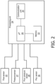
- FIG. 2 is a block diagram of processing unit 24 in accordance with a non-limiting exemplary embodiment of the disclosed concept.
- Processing unit 24 includes a processor 30, a memory 32, and a communication unit 34.
- Processor 30 may form all or part of a processing portion which may be, for example, a microprocessor, a microcontroller or some other suitable processing device.
- Memory 32 may form all or part of a memory portion that may be internal to the processing portion or operatively coupled to the processing portion and provide a storage medium for data and software executable by the processing portion for implementing functionality of processing unit 23 and controlling the operation of pressure support system 2.
- Memory 32 can be any of one or more of a variety of types of internal and/or external storage media such as, without limitation, RAM, ROM, EPROM(s), EEPROM(s), FLASH, and the like that provide a storage register, i.e., a machine readable medium, for data storage such as in the fashion of an internal storage area of a computer, and can be volatile memory or nonvolatile memory.
- Communication unit 34 may provide for communication between processing unit 24 and other components of pressure support device 4, components of the patient circuit, or other external devices.
- communication unit 34 may facilitate communication with various sensors such as flow control sensor 22.
- Communication unit 34 may also facilitate communication with external devices.
- communication unit 34 may facilitate communication with electronic devices such as a phone, tablet, computer, or other devices directly or via a network. Communication facilitated by communication unit 34 may allow processing unit 24 to send and/or receive data from the component or device it communicates with.
- processing unit 24 receives outputs from one or more sensors including flow sensor 22, pressure sensor 27, proximal pressure sensor 28, and body position sensor 36.
- processing unit 24 may further receive outputs from one or more other types of sensors that are not shown in FIG. 2 .
- processing unit 24 may further receive outputs from one or more of a temperature sensor, a proximity/contact sensor, location sensors, microphones, or identification sensors.
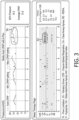
- FIG. 3 is a graph of a pressure compensation regimen and detected disordered breathing events in accordance with an example embodiment of the disclosed concept.
- the pressure compensation regimen may be provided by pressure support device 4 and the disordered breathing events may be detected by processing unit 24 based on outputs of one or more sensors including flow sensor 22, pressure sensor 27, and/or proximate pressure sensor 28.
- Highlighted in FIG. 3 are a pressure compensation regimen 50 and a series of disordered breathing events 52.
- FIG. 3 covers a period of 8 hours. From hours 0 to about 6.5, the pressure compensation regimen is primarily effective in relieving disordered breathing events that arise. However, at about hour 6.5 disordered breathing events 52 (e.g., obstructive apneas) are detected and persists until after hour 7.
- disordered breathing events 52 e.g., obstructive apneas
- pressure compensation regimen 50 includes three series of increases in pressure, each containing three pressure increases, but disordered breathing events 52 persist until at least the third series of increases in pressure. While disordered breathing events 52 eventually subside, it is more likely responsive to a change in the patient condition (e.g., sleep state or body position) rather than an effect of the pressure compensation regimen.
- processing unit 24 may determine that the pressure compensation regimen is not effective and output the alert based on pressure compensation regimen 50 and disordered breathing events 52 from about hour 6.5 to after hour 7. For example, processing unit 24 may determine that the pressure compensation regimen is not effective based on the persistence of the disordered breathing events for a predetermined period of time and/or based on the lack of effectiveness of changes in the pressure compensation regimen.
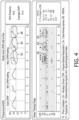
- FIG. 4 is a graph of a pressure compensation regimen and detected disordered breathing events in accordance with an example embodiment of the disclosed concept.
- the pressure compensation regimen may be provided by pressure support device 4 and the disordered breathing events may be detected by processing unit 24 based on outputs of one or more sensors including flow sensor 22, pressure sensor 27, and/or proximate pressure sensor 28.
- Highlighted in FIG. 4 are a pressure compensation regimens 54, 56, and 58 and corresponding series of disordered breathing events 60, 62, and 64. Similar to FIG. 3 , the highlighted disordered breathing events 60, 62, and 64 in FIG. 4 persist through changes in their corresponding pressure compensation regimens 54, 56, and 58.
- the highlighted pressure compensation regimens 54, 56, and 58 and corresponding disordered breathing events 60, 62, and 64 in FIG. 4 are additional examples of patterns which may trigger processing unit 24 to output the alert.
- FIG. 5 is a graph of a pressure compensation regimen and detected disordered breathing events in accordance with an example embodiment of the disclosed concept.
- the graph in FIG. 5 corresponds to a pressure compensation regimen provided by an adaptive servo ventilation (ASV) device, rather than a CPAP device.
- the pressure compensation regimen may be provided by pressure support device 4 and the disordered breathing events may be detected by processing unit 24 based on outputs of one or more sensors including flow sensor 22, pressure sensor 27, and/or proximate pressure sensor 28.
- Highlighted in FIG. 5 is a pressure compensation regimen 66 and corresponding series of disordered breathing events 68. Similar to FIGS.
- the highlighted series of disordered breathing events 68 persist through the highlighted pressure compensation regimen 66.
- the highlighted pressure compensation regimen 66 and corresponding series of disordered breathing events 68 in FIG. 5 are additional examples of patterns which may trigger processing unit 24 to output the alert.
- FIG. 6 is a graph of an airflow waveform of a patient and corresponding pressure compensation regimen in accordance with an example embodiment of the disclosed concept.
- the pressure compensation regimen may be provided by pressure support device 4 and the airflow waveform may be detected by processing unit 24 based on outputs of one or more sensors including flow sensor 22, pressure sensor 27, and/or proximate pressure sensor 28.
- the bumps in the airflow waveform are test pulses that are provided to the airway. Because there is not airflow in response to the pressure test pulses, it can be determined that the airway is closed. Alternatively, if there was airflow in response to the pressure test pulses, it can be determined that the airway is open. It should also be noted that there are other methods known to those skilled in the art to test the patency of the patient's airway and it will be appreciated that such other methods may be employed in conjunction with the present concept.
- the degree of patency of the patient's airway i.e. the extent of closure, or the pressure-sensitivity of the closure
- the epiglottis is like a one-way valve, it is likely to not yield in response to a larger test pulse (e.g., a 10+cmH2O pressure pulse) and will show zero airflow, whereas a different site of collapse (e.g. soft palate) may show some smaller amount of airflow in response.
- a continued "no response" to larger pressure test pulses would be an early indicator of disordered breathing events that are unlikely to be responsive to pressure.
- an alert could be provided to the patient.
- the alert may only be provided if the titrated pressure provided to the patient was already above a predetermined threshold.
- a disordered breathing event 70 (e.g., an apnea) occurs when airflow stops. As shown in FIG. 6 , the disordered breathing event 70 occurs in a series that continues to persist and is not completely relieved by the pressure compensation regimen.
- the pressure compensation regimen includes increases in pressure 72. Despite the increases in pressure 72, disordered breathing event 70 persists. Processing unit 24 may, for example, determine that the pressure compensation regimen is not effective based on disordered breathing event 70 persisting through changes in the pressure compensation regimen.
- FIGS. 7A, 7B, and 7C are graphs of an airflow waveform of a patient for a single breath in accordance with an example embodiment of the disclosed concept.
- FIG. 7A is a waveform of an example of an airflow waveform for a nominal breath (e.g., no disordered breathing event).
- FIG. 7B is a waveform of an example of an airflow waveform for a breath during a soft palate collapse.
- FIG. 7C is a waveform of an example of an airflow waveform for a breath during an epiglottic collapse.
- FIG. 7C shows a short inhalation with a quick fall to zero airflow, much earlier than would be expected with a nominal breath, which is indicative of an epiglottic collapse.
- Processing unit 24 may output the alert based on detecting a waveform similar to that shown in FIG. 7C .
- processing unit 24 may determine other sites of (and degrees of) airway closure (e.g. tongue base or vocal cords) that may be determinable from the airflow waveform and use that in determining whether the pressure compensation regimen is effective and whether output the alert (e.g., without limitation, a tongue base collapse may be more effectively treated by positional therapy).
- sites of (and degrees of) airway closure e.g. tongue base or vocal cords
- processing unit 24 may determine other sites of (and degrees of) airway closure (e.g. tongue base or vocal cords) that may be determinable from the airflow waveform and use that in determining whether the pressure compensation regimen is effective and whether output the alert (e.g., without limitation, a tongue base collapse may be more effectively treated by positional therapy).
- FIG. 8 is a flowchart of a method, not according to the invention as claimed, of providing an alert for a non-effective pressure compensation regimen in accordance with an example embodiment of the disclosed concept.
- the method of FIG. 8 may be implemented, for example, by pressure support device 4 of FIG. 1 . However, it will be appreciated that the method of FIG. 8 may also be implemented in other devices without departing from the scope of the disclosed concept.
- the method of FIG. 8 begins at 80 where pressure support device 4 provides a pressure compensation regimen to patient 10.
- processing unit 24 determines whether a disordered breathing event (e.g., an obstructive apnea) is present based on outputs of one or more sensors (e.g., flow sensor 22, pressure sensor 27, and/or proximate pressure sensor 28). If the disordered breathing event is not present, the method returns to 80 and pressure support device 4 continues to provide the pressure compensation regimen. However, if the disordered breathing event is present, processing unit 24 proceeds to 84 and determines whether the pressure compensation regimen is effective in relieving the disordered breathing event.
- a disordered breathing event e.g., an obstructive apnea
- Processing unit 24 may use any method described herein to determine whether the pressure compensation regimen is effective in relieving the disordered breathing event (e.g., without limitation, whether disordered breathing events persist for a predetermined period of time, whether disordered breathing events persist through changes in the pressure compensation regimen, etc.).
- processing unit 24 determines that the pressure compensation regimen is effective in relieving the disordered breathing event, the method returns to 80 and pressure support device 4 continues to provide the pressure compensation regimen. However, if processing unit 24 determines that the pressure compensation regimen is not effective in relieving the disordered breathing event, the method proceeds to 86 and processing unit 24 outputs the alert.
- the alert may be outputted using any method described herein (e.g., output to an indicator, output to an extemal device, etc.). It will also be appreciated that pressure support device may continue to provide the pressure compensation regimen through the method of FIG. 8 and continue to provide the pressure compensation regimen after the alert has been output.
- the computer readable recording medium is any data storage device that can store data which can be thereafter read by a computer system.
- Examples of the computer readable recording medium include read-only memory (ROM), random-access memory (RAM), CD-ROMs, magnetic tapes, floppy disks, and optical data storage devices.
- any reference signs placed between parentheses shall not be construed as limiting the claim.
- the word “comprising” or “including” does not exclude the presence of elements or steps other than those listed in a claim.
- several of these means may be embodied by one and the same item of hardware.
- the word “a” or “an” preceding an element does not exclude the presence of a plurality of such elements.
- any device claim enumerating several means several of these means may be embodied by one and the same item of hardware.
- the mere fact that certain elements are recited in mutually different dependent claims does not indicate that these elements cannot be used in combination.
Landscapes
- Health & Medical Sciences (AREA)
- Life Sciences & Earth Sciences (AREA)
- General Health & Medical Sciences (AREA)
- Public Health (AREA)
- Engineering & Computer Science (AREA)
- Biomedical Technology (AREA)
- Heart & Thoracic Surgery (AREA)
- Veterinary Medicine (AREA)
- Animal Behavior & Ethology (AREA)
- Pulmonology (AREA)
- Biophysics (AREA)
- Physics & Mathematics (AREA)
- Pathology (AREA)
- Medical Informatics (AREA)
- Molecular Biology (AREA)
- Surgery (AREA)
- Emergency Medicine (AREA)
- Hematology (AREA)
- Anesthesiology (AREA)
- Physiology (AREA)
- Measurement Of The Respiration, Hearing Ability, Form, And Blood Characteristics Of Living Organisms (AREA)
Applications Claiming Priority (2)
| Application Number | Priority Date | Filing Date | Title |
|---|---|---|---|
| US201762565388P | 2017-09-29 | 2017-09-29 | |
| PCT/EP2018/076369 WO2019063744A1 (en) | 2017-09-29 | 2018-09-27 | PRESSURE SUPPORT VENTILATION DEVICE AND METHOD FOR PROVIDING AN ALERT FOR AN EFFICIENT PRESSURE COMPENSATION REGIME |
Publications (2)
| Publication Number | Publication Date |
|---|---|
| EP3687609A1 EP3687609A1 (en) | 2020-08-05 |
| EP3687609B1 true EP3687609B1 (en) | 2025-03-19 |
Family
ID=63798957
Family Applications (1)
| Application Number | Title | Priority Date | Filing Date |
|---|---|---|---|
| EP18783391.8A Active EP3687609B1 (en) | 2017-09-29 | 2018-09-27 | Pressure support device |
Country Status (5)
| Country | Link |
|---|---|
| US (1) | US11191917B2 (enExample) |
| EP (1) | EP3687609B1 (enExample) |
| JP (1) | JP7100697B2 (enExample) |
| CN (1) | CN111163823B (enExample) |
| WO (1) | WO2019063744A1 (enExample) |
Families Citing this family (5)
| Publication number | Priority date | Publication date | Assignee | Title |
|---|---|---|---|---|
| DE102018008493A1 (de) * | 2018-10-30 | 2020-04-30 | Drägerwerk AG & Co. KGaA | Transfereinheit, Beatmungsvorrichtung, Beatmungssystem sowie Verfahren zum Wechsel einer für einen Beatmungsvorgang eines Patienten verwendeten Beatmungsvorrichtung |
| WO2021078913A1 (en) * | 2019-10-22 | 2021-04-29 | Oxypoint Nv | Vital parameter measurements for low care patients |
| EP4125572A1 (en) * | 2020-03-31 | 2023-02-08 | ResMed Sensor Technologies Limited | System and method for mapping an airway obstruction |
| EP4103048A4 (en) * | 2020-09-30 | 2024-03-20 | ResMed Pty Ltd | SYSTEMS AND METHODS FOR DIAGNOSING THERAPY TERMINATION |
| WO2022175487A1 (en) * | 2021-02-22 | 2022-08-25 | Koninklijke Philips N.V. | Method for providing comfort feature in a pressure support device and pressure support device including same |
Citations (1)
| Publication number | Priority date | Publication date | Assignee | Title |
|---|---|---|---|---|
| US7942824B1 (en) * | 2005-11-04 | 2011-05-17 | Cleveland Medical Devices Inc. | Integrated sleep diagnostic and therapeutic system and method |
Family Cites Families (26)
| Publication number | Priority date | Publication date | Assignee | Title |
|---|---|---|---|---|
| US5632269A (en) | 1989-09-22 | 1997-05-27 | Respironics Inc. | Breathing gas delivery method and apparatus |
| US5148802B1 (en) | 1989-09-22 | 1997-08-12 | Respironics Inc | Method and apparatus for maintaining airway patency to treat sleep apnea and other disorders |
| US6675797B1 (en) * | 1993-11-05 | 2004-01-13 | Resmed Limited | Determination of patency of the airway |
| US5603315A (en) * | 1995-08-14 | 1997-02-18 | Reliable Engineering | Multiple mode oxygen delivery system |
| US6920875B1 (en) | 1999-06-15 | 2005-07-26 | Respironics, Inc. | Average volume ventilation |
| US7708697B2 (en) | 2000-04-20 | 2010-05-04 | Pulmosonix Pty Ltd | Method and apparatus for determining conditions of biological tissues |
| US6626175B2 (en) | 2000-10-06 | 2003-09-30 | Respironics, Inc. | Medical ventilator triggering and cycling method and mechanism |
| US7115097B2 (en) * | 2003-10-09 | 2006-10-03 | Johnson Joseph L | Positive airway pressure notification system for treatment of breathing disorders during sleep |
| CN101920053B (zh) * | 2003-11-26 | 2013-03-06 | 雷斯梅德有限公司 | 睡眠呼吸障碍治疗的宏观控制 |
| US20070208269A1 (en) * | 2004-05-18 | 2007-09-06 | Mumford John R | Mask assembly, system and method for determining the occurrence of respiratory events using frontal electrode array |
| US8528551B2 (en) | 2005-06-14 | 2013-09-10 | Resmed Limited | Acclimatization therapy for first time users |
| WO2007088539A2 (en) * | 2006-01-31 | 2007-08-09 | Technion Research & Development Foundation Ltd. | Method device and system for monitoring lung ventilation |
| CA2696773A1 (en) * | 2007-08-23 | 2009-02-26 | Invacare Corporation | Method and apparatus for adjusting desired pressure in positive airway pressure devices |
| CN101618247B (zh) * | 2008-07-03 | 2012-05-16 | 周常安 | 可扩充式气体递送系统 |
| US10857319B2 (en) * | 2011-01-14 | 2020-12-08 | Koninklijke Philips N.V. | Measuring continuity of therapy associated with a respiratory treatment device |
| US8327846B2 (en) * | 2011-02-08 | 2012-12-11 | Hancock Medical, Inc. | Positive airway pressure system with head position control |
| US9162032B2 (en) | 2011-03-21 | 2015-10-20 | William Ray Lynch, JR. | Systems and methods for diagnosing and treating sleep disorders |
| US10576223B2 (en) * | 2011-06-15 | 2020-03-03 | Koninklijke Phlips N.V. | Unlocking a respiratory therapy mode |
| EP2822624B1 (en) * | 2012-03-09 | 2017-04-19 | Hancock Medical, Inc. | Positive airway pressure system with head position control |
| WO2014117179A1 (en) * | 2013-01-28 | 2014-07-31 | Hancock Medical, Inc. | Position control devices and methods for use with positive airway pressure systems |
| US20160015916A1 (en) * | 2013-03-15 | 2016-01-21 | Hancock Medical, Inc. | Positive airway pressure systems |
| US9585601B2 (en) * | 2013-08-15 | 2017-03-07 | Chunyuan Qiu | Systems, methods and devices for diagnosing sleep apnea |
| DE102014003542B4 (de) | 2014-03-12 | 2021-09-30 | Drägerwerk AG & Co. KGaA | Verfahren und Vorrichtung zur Erzeugung eines Alarms während einer maschinellen Patientenbeatmung |
| US9848819B2 (en) | 2014-05-19 | 2017-12-26 | Eric James Kezirian | Airflow and airway factors |
| DE102015015439A1 (de) | 2015-12-02 | 2017-06-08 | Drägerwerk AG & Co. KGaA | Beatmungsvorrichtung und Verfahren zur automatischen Beatmung eines Patienten |
| CN106333811A (zh) * | 2016-10-03 | 2017-01-18 | 成都美爱康医疗科技有限公司 | 一种睡眠呼吸暂停自动翻身床 |
-
2018
- 2018-09-27 EP EP18783391.8A patent/EP3687609B1/en active Active
- 2018-09-27 US US16/143,675 patent/US11191917B2/en active Active
- 2018-09-27 WO PCT/EP2018/076369 patent/WO2019063744A1/en not_active Ceased
- 2018-09-27 JP JP2020517805A patent/JP7100697B2/ja active Active
- 2018-09-27 CN CN201880062479.8A patent/CN111163823B/zh active Active
Patent Citations (1)
| Publication number | Priority date | Publication date | Assignee | Title |
|---|---|---|---|---|
| US7942824B1 (en) * | 2005-11-04 | 2011-05-17 | Cleveland Medical Devices Inc. | Integrated sleep diagnostic and therapeutic system and method |
Also Published As
| Publication number | Publication date |
|---|---|
| CN111163823B (zh) | 2023-04-28 |
| JP7100697B2 (ja) | 2022-07-13 |
| US20190099571A1 (en) | 2019-04-04 |
| WO2019063744A1 (en) | 2019-04-04 |
| EP3687609A1 (en) | 2020-08-05 |
| CN111163823A (zh) | 2020-05-15 |
| JP2020534946A (ja) | 2020-12-03 |
| US11191917B2 (en) | 2021-12-07 |
Similar Documents
| Publication | Publication Date | Title |
|---|---|---|
| EP2401017B1 (en) | Automatic pressure titration | |
| EP2510966B1 (en) | Apparatus for resolving upper airway instability | |
| EP3687609B1 (en) | Pressure support device | |
| US11351318B2 (en) | Pressure support device and method of determining changes in a patient circuit | |
| RU2594808C2 (ru) | Система и способ для лечения синдрома гиповентиляции при ожирении | |
| US12161805B2 (en) | System and method for providing enhanced pap metrics | |
| CN106029142A (zh) | 针对呼吸障碍诊断的逆双正气道压力挑战 | |
| WO2020136035A1 (en) | Pressure support system and method of providing pressure support therapy to a patient | |
| US11844898B2 (en) | System and method for detecting stroke in patients during pressure support therapy | |
| EP3815101B1 (en) | System and method for increasing adherence to a pressure support therapy | |
| US20220265946A1 (en) | Method for providing pressure comfort feature in a pressure support device and pressure support device including same | |
| US20220265942A1 (en) | Method for providing comfort feature in a pressure support device and pressure support device including same |
Legal Events
| Date | Code | Title | Description |
|---|---|---|---|
| STAA | Information on the status of an ep patent application or granted ep patent |
Free format text: STATUS: UNKNOWN |
|
| STAA | Information on the status of an ep patent application or granted ep patent |
Free format text: STATUS: THE INTERNATIONAL PUBLICATION HAS BEEN MADE |
|
| PUAI | Public reference made under article 153(3) epc to a published international application that has entered the european phase |
Free format text: ORIGINAL CODE: 0009012 |
|
| STAA | Information on the status of an ep patent application or granted ep patent |
Free format text: STATUS: REQUEST FOR EXAMINATION WAS MADE |
|
| 17P | Request for examination filed |
Effective date: 20200429 |
|
| AK | Designated contracting states |
Kind code of ref document: A1 Designated state(s): AL AT BE BG CH CY CZ DE DK EE ES FI FR GB GR HR HU IE IS IT LI LT LU LV MC MK MT NL NO PL PT RO RS SE SI SK SM TR |
|
| AX | Request for extension of the european patent |
Extension state: BA ME |
|
| DAV | Request for validation of the european patent (deleted) | ||
| DAX | Request for extension of the european patent (deleted) | ||
| STAA | Information on the status of an ep patent application or granted ep patent |
Free format text: STATUS: EXAMINATION IS IN PROGRESS |
|
| 17Q | First examination report despatched |
Effective date: 20220622 |
|
| GRAP | Despatch of communication of intention to grant a patent |
Free format text: ORIGINAL CODE: EPIDOSNIGR1 |
|
| STAA | Information on the status of an ep patent application or granted ep patent |
Free format text: STATUS: GRANT OF PATENT IS INTENDED |
|
| RIC1 | Information provided on ipc code assigned before grant |
Ipc: A61B 5/11 20060101ALN20240930BHEP Ipc: A61B 5/00 20060101ALN20240930BHEP Ipc: A61B 5/087 20060101ALI20240930BHEP Ipc: A61B 5/08 20060101ALI20240930BHEP Ipc: A61M 16/00 20060101AFI20240930BHEP |
|
| INTG | Intention to grant announced |
Effective date: 20241017 |
|
| RIN1 | Information on inventor provided before grant (corrected) |
Inventor name: SHELLY, BENJAMIN IRWIN |
|
| GRAS | Grant fee paid |
Free format text: ORIGINAL CODE: EPIDOSNIGR3 |
|
| GRAA | (expected) grant |
Free format text: ORIGINAL CODE: 0009210 |
|
| STAA | Information on the status of an ep patent application or granted ep patent |
Free format text: STATUS: THE PATENT HAS BEEN GRANTED |
|
| AK | Designated contracting states |
Kind code of ref document: B1 Designated state(s): AL AT BE BG CH CY CZ DE DK EE ES FI FR GB GR HR HU IE IS IT LI LT LU LV MC MK MT NL NO PL PT RO RS SE SI SK SM TR |
|
| REG | Reference to a national code |
Ref country code: GB Ref legal event code: FG4D |
|
| REG | Reference to a national code |
Ref country code: CH Ref legal event code: EP |
|
| REG | Reference to a national code |
Ref country code: IE Ref legal event code: FG4D |
|
| REG | Reference to a national code |
Ref country code: DE Ref legal event code: R096 Ref document number: 602018080281 Country of ref document: DE |
|
| PG25 | Lapsed in a contracting state [announced via postgrant information from national office to epo] |
Ref country code: RS Free format text: LAPSE BECAUSE OF FAILURE TO SUBMIT A TRANSLATION OF THE DESCRIPTION OR TO PAY THE FEE WITHIN THE PRESCRIBED TIME-LIMIT Effective date: 20250619 |
|
| PG25 | Lapsed in a contracting state [announced via postgrant information from national office to epo] |
Ref country code: FI Free format text: LAPSE BECAUSE OF FAILURE TO SUBMIT A TRANSLATION OF THE DESCRIPTION OR TO PAY THE FEE WITHIN THE PRESCRIBED TIME-LIMIT Effective date: 20250319 |
|
| REG | Reference to a national code |
Ref country code: LT Ref legal event code: MG9D |
|
| PG25 | Lapsed in a contracting state [announced via postgrant information from national office to epo] |
Ref country code: NO Free format text: LAPSE BECAUSE OF FAILURE TO SUBMIT A TRANSLATION OF THE DESCRIPTION OR TO PAY THE FEE WITHIN THE PRESCRIBED TIME-LIMIT Effective date: 20250619 |
|
| PG25 | Lapsed in a contracting state [announced via postgrant information from national office to epo] |
Ref country code: HR Free format text: LAPSE BECAUSE OF FAILURE TO SUBMIT A TRANSLATION OF THE DESCRIPTION OR TO PAY THE FEE WITHIN THE PRESCRIBED TIME-LIMIT Effective date: 20250319 |
|
| PG25 | Lapsed in a contracting state [announced via postgrant information from national office to epo] |
Ref country code: LV Free format text: LAPSE BECAUSE OF FAILURE TO SUBMIT A TRANSLATION OF THE DESCRIPTION OR TO PAY THE FEE WITHIN THE PRESCRIBED TIME-LIMIT Effective date: 20250319 |
|
| PG25 | Lapsed in a contracting state [announced via postgrant information from national office to epo] |
Ref country code: GR Free format text: LAPSE BECAUSE OF FAILURE TO SUBMIT A TRANSLATION OF THE DESCRIPTION OR TO PAY THE FEE WITHIN THE PRESCRIBED TIME-LIMIT Effective date: 20250620 Ref country code: BG Free format text: LAPSE BECAUSE OF FAILURE TO SUBMIT A TRANSLATION OF THE DESCRIPTION OR TO PAY THE FEE WITHIN THE PRESCRIBED TIME-LIMIT Effective date: 20250319 |
|
| REG | Reference to a national code |
Ref country code: NL Ref legal event code: MP Effective date: 20250319 |
|
| REG | Reference to a national code |
Ref country code: AT Ref legal event code: MK05 Ref document number: 1776442 Country of ref document: AT Kind code of ref document: T Effective date: 20250319 |
|
| PG25 | Lapsed in a contracting state [announced via postgrant information from national office to epo] |
Ref country code: NL Free format text: LAPSE BECAUSE OF FAILURE TO SUBMIT A TRANSLATION OF THE DESCRIPTION OR TO PAY THE FEE WITHIN THE PRESCRIBED TIME-LIMIT Effective date: 20250319 |
|
| PG25 | Lapsed in a contracting state [announced via postgrant information from national office to epo] |
Ref country code: SE Free format text: LAPSE BECAUSE OF FAILURE TO SUBMIT A TRANSLATION OF THE DESCRIPTION OR TO PAY THE FEE WITHIN THE PRESCRIBED TIME-LIMIT Effective date: 20250319 |
|
| PG25 | Lapsed in a contracting state [announced via postgrant information from national office to epo] |
Ref country code: SM Free format text: LAPSE BECAUSE OF FAILURE TO SUBMIT A TRANSLATION OF THE DESCRIPTION OR TO PAY THE FEE WITHIN THE PRESCRIBED TIME-LIMIT Effective date: 20250319 |
|
| PG25 | Lapsed in a contracting state [announced via postgrant information from national office to epo] |
Ref country code: PT Free format text: LAPSE BECAUSE OF FAILURE TO SUBMIT A TRANSLATION OF THE DESCRIPTION OR TO PAY THE FEE WITHIN THE PRESCRIBED TIME-LIMIT Effective date: 20250721 Ref country code: ES Free format text: LAPSE BECAUSE OF FAILURE TO SUBMIT A TRANSLATION OF THE DESCRIPTION OR TO PAY THE FEE WITHIN THE PRESCRIBED TIME-LIMIT Effective date: 20250319 |
|
| PGFP | Annual fee paid to national office [announced via postgrant information from national office to epo] |
Ref country code: DE Payment date: 20250926 Year of fee payment: 8 |
|
| PG25 | Lapsed in a contracting state [announced via postgrant information from national office to epo] |
Ref country code: IT Free format text: LAPSE BECAUSE OF FAILURE TO SUBMIT A TRANSLATION OF THE DESCRIPTION OR TO PAY THE FEE WITHIN THE PRESCRIBED TIME-LIMIT Effective date: 20250319 Ref country code: PL Free format text: LAPSE BECAUSE OF FAILURE TO SUBMIT A TRANSLATION OF THE DESCRIPTION OR TO PAY THE FEE WITHIN THE PRESCRIBED TIME-LIMIT Effective date: 20250319 |
|
| PG25 | Lapsed in a contracting state [announced via postgrant information from national office to epo] |
Ref country code: AT Free format text: LAPSE BECAUSE OF FAILURE TO SUBMIT A TRANSLATION OF THE DESCRIPTION OR TO PAY THE FEE WITHIN THE PRESCRIBED TIME-LIMIT Effective date: 20250319 |
|
| PG25 | Lapsed in a contracting state [announced via postgrant information from national office to epo] |
Ref country code: EE Free format text: LAPSE BECAUSE OF FAILURE TO SUBMIT A TRANSLATION OF THE DESCRIPTION OR TO PAY THE FEE WITHIN THE PRESCRIBED TIME-LIMIT Effective date: 20250319 Ref country code: CZ Free format text: LAPSE BECAUSE OF FAILURE TO SUBMIT A TRANSLATION OF THE DESCRIPTION OR TO PAY THE FEE WITHIN THE PRESCRIBED TIME-LIMIT Effective date: 20250319 |
|
| PG25 | Lapsed in a contracting state [announced via postgrant information from national office to epo] |
Ref country code: RO Free format text: LAPSE BECAUSE OF FAILURE TO SUBMIT A TRANSLATION OF THE DESCRIPTION OR TO PAY THE FEE WITHIN THE PRESCRIBED TIME-LIMIT Effective date: 20250319 |
|
| PG25 | Lapsed in a contracting state [announced via postgrant information from national office to epo] |
Ref country code: SK Free format text: LAPSE BECAUSE OF FAILURE TO SUBMIT A TRANSLATION OF THE DESCRIPTION OR TO PAY THE FEE WITHIN THE PRESCRIBED TIME-LIMIT Effective date: 20250319 |
|
| PG25 | Lapsed in a contracting state [announced via postgrant information from national office to epo] |
Ref country code: IS Free format text: LAPSE BECAUSE OF FAILURE TO SUBMIT A TRANSLATION OF THE DESCRIPTION OR TO PAY THE FEE WITHIN THE PRESCRIBED TIME-LIMIT Effective date: 20250719 |