EP3687117B1 - Systems and methods for isolating network traffic of multiple users across networks of computing platforms - Google Patents
Systems and methods for isolating network traffic of multiple users across networks of computing platforms Download PDFInfo
- Publication number
- EP3687117B1 EP3687117B1 EP19184504.9A EP19184504A EP3687117B1 EP 3687117 B1 EP3687117 B1 EP 3687117B1 EP 19184504 A EP19184504 A EP 19184504A EP 3687117 B1 EP3687117 B1 EP 3687117B1
- Authority
- EP
- European Patent Office
- Prior art keywords
- network
- user
- computing platform
- route
- routing table
- Prior art date
- Legal status (The legal status is an assumption and is not a legal conclusion. Google has not performed a legal analysis and makes no representation as to the accuracy of the status listed.)
- Active
Links
- 238000000034 method Methods 0.000 title claims description 53
- 230000006855 networking Effects 0.000 claims description 72
- 230000004044 response Effects 0.000 claims description 8
- 238000004519 manufacturing process Methods 0.000 description 31
- 238000007726 management method Methods 0.000 description 23
- 238000010586 diagram Methods 0.000 description 18
- 230000008569 process Effects 0.000 description 14
- 238000003860 storage Methods 0.000 description 9
- 238000002955 isolation Methods 0.000 description 7
- 230000004048 modification Effects 0.000 description 7
- 238000012986 modification Methods 0.000 description 7
- 238000005516 engineering process Methods 0.000 description 6
- 238000004891 communication Methods 0.000 description 5
- 230000006870 function Effects 0.000 description 5
- 238000004590 computer program Methods 0.000 description 3
- 238000013500 data storage Methods 0.000 description 3
- 238000012545 processing Methods 0.000 description 3
- 230000002776 aggregation Effects 0.000 description 2
- 238000004220 aggregation Methods 0.000 description 2
- 230000008901 benefit Effects 0.000 description 2
- 230000007246 mechanism Effects 0.000 description 2
- 230000008859 change Effects 0.000 description 1
- 230000003247 decreasing effect Effects 0.000 description 1
- 230000001419 dependent effect Effects 0.000 description 1
- 230000006872 improvement Effects 0.000 description 1
- 238000002347 injection Methods 0.000 description 1
- 239000007924 injection Substances 0.000 description 1
- 238000013507 mapping Methods 0.000 description 1
- 230000003287 optical effect Effects 0.000 description 1
- 230000001902 propagating effect Effects 0.000 description 1
- 239000000243 solution Substances 0.000 description 1
- 230000003068 static effect Effects 0.000 description 1
Images


Classifications
-
- H—ELECTRICITY
- H04—ELECTRIC COMMUNICATION TECHNIQUE
- H04L—TRANSMISSION OF DIGITAL INFORMATION, e.g. TELEGRAPHIC COMMUNICATION
- H04L12/00—Data switching networks
- H04L12/28—Data switching networks characterised by path configuration, e.g. LAN [Local Area Networks] or WAN [Wide Area Networks]
- H04L12/46—Interconnection of networks
-
- H—ELECTRICITY
- H04—ELECTRIC COMMUNICATION TECHNIQUE
- H04L—TRANSMISSION OF DIGITAL INFORMATION, e.g. TELEGRAPHIC COMMUNICATION
- H04L45/00—Routing or path finding of packets in data switching networks
- H04L45/74—Address processing for routing
- H04L45/745—Address table lookup; Address filtering
-
- H—ELECTRICITY
- H04—ELECTRIC COMMUNICATION TECHNIQUE
- H04L—TRANSMISSION OF DIGITAL INFORMATION, e.g. TELEGRAPHIC COMMUNICATION
- H04L45/00—Routing or path finding of packets in data switching networks
- H04L45/302—Route determination based on requested QoS
- H04L45/308—Route determination based on user's profile, e.g. premium users
-
- H—ELECTRICITY
- H04—ELECTRIC COMMUNICATION TECHNIQUE
- H04L—TRANSMISSION OF DIGITAL INFORMATION, e.g. TELEGRAPHIC COMMUNICATION
- H04L45/00—Routing or path finding of packets in data switching networks
- H04L45/54—Organization of routing tables
-
- H—ELECTRICITY
- H04—ELECTRIC COMMUNICATION TECHNIQUE
- H04L—TRANSMISSION OF DIGITAL INFORMATION, e.g. TELEGRAPHIC COMMUNICATION
- H04L45/00—Routing or path finding of packets in data switching networks
- H04L45/74—Address processing for routing
- H04L45/745—Address table lookup; Address filtering
- H04L45/7452—Multiple parallel or consecutive lookup operations
-
- H—ELECTRICITY
- H04—ELECTRIC COMMUNICATION TECHNIQUE
- H04L—TRANSMISSION OF DIGITAL INFORMATION, e.g. TELEGRAPHIC COMMUNICATION
- H04L61/00—Network arrangements, protocols or services for addressing or naming
- H04L61/09—Mapping addresses
- H04L61/25—Mapping addresses of the same type
- H04L61/2503—Translation of Internet protocol [IP] addresses
- H04L61/2592—Translation of Internet protocol [IP] addresses using tunnelling or encapsulation
Definitions
- Certain embodiments of the present invention are directed to computing platforms including hosts and networking devices. More particularly, some embodiments of the present invention provide systems and methods for isolating network traffic of multiple users across networks of computing platforms.
- US 9 014 191 discloses a system for forwarding a data packet between network components in a virtualized network system.
- US 2015/326467 discloses technology for bridging clouds of computing devices for compute and data storage.
- Conventional systems and methods are often not capable of efficiently isolating network traffic of multiple users associated with different customers across a network of a computing platform.
- Conventional systems and methods typically use firewalls and access control lists to guarantee data security of network traffic at the network layer within a multi-tenant computing platform, which leads to increased cost and decreased efficiency, and is more difficult to manage when scaling up the platform.
- benefits include significant improvements, including, for example, increased efficiency, reduced complexity, and improved scalability, in managing network traffic of an increased number of users across a network of a computing platform.
- other benefits include increased data security at the networking level of the computing platform.
- systems and methods are configured to isolate network traffic of multiple users across a network of a computing platform.
- one or more solutions rooted in computer technology overcome one or more problems specifically arising in the realm of computer technology.
- Some embodiments are directed to computing platforms including hosts and networking devices. More particularly, some embodiments of the present invention provide systems and methods for isolating network traffic of multiple users across networks of computing platforms.
- the computing platforms include virtual servers or virtual machines.
- the computing platforms include a virtual computing environment that provides an operating system and/or an application server for running one or more containers.
- a container includes a containerized application.
- one or more containers run on a server or host machine of the computing platform and are associated with particular resources that include CPU, memory, storage, and/or networking capacity.
- network traffic for multiple users associated with different customers (e.g., different tenants) of a multi-tenant computing platform is isolated at the network layer of the network by having separate routing tables for each user. This, for example, eliminates the need for firewalls and access control lists to guarantee data security in the multi-tenant computing platform.
- a user represents a group of users. As an example, the group of users is associated with a customer (e.g., a tenant) of the multi-tenant computing platform.
- each user is associated with only one customer (e.g., only one tenant) of the multi-tenant computing platform that provides services to multiple customers.
- each routing table is associated with a unique user identification number to isolate network routes in one routing tables from routes in another routing table based at least in part on the unique user identification number.
- the routing tables reside on networking devices of the computing platform, which direct data packets tagged with the unique user identification number based on routes in the routing table associated with the same unique user identification number.
- the unique user identification number represents a unique customer identification number.
- the isolation of routes at the network layer of the network mirrors the isolation of broadcast domains of the computing platform at the data link layer of the network.
- the isolation at the data link layer is based on the same unique user identification number and extended over the network layer of the network.
- systems and methods allow for leaking routes between separate routing tables and sharing default routes with all user of the computing platform. For example, each separate routing table is associated with a different unique user identification number.
- configuration of networking devices, including configuration of the routing tables on the networking devices, is managed through a management network that is separate from the network used by the users' network traffic.
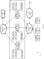
- FIG. 1 is a simplified diagram showing a system 100 for isolating network traffic of multiple users across a network of a computing platform 102 according to one embodiment of the present invention.
- the system 100 includes the computing platform 102, a network 104 (e.g., a production network), a plurality of hosts 106 1-m , 108 1-n , 110 1-o , and one or more networking devices 112 1-N .
- hosts 106 1-m represent hosts 106 1 , ..., 106 m as shown in FIG.
- hosts 108 1-n represent hosts 108 1 , ..., 108 n as shown in FIG. 1
- hosts 110 1-o represent hosts 110 1 , ..., 110 o as shown in FIG. 1
- networking devices 112 1-N represent networking devices 112 1 , ..., 112 N as shown in FIG. 1 .
- the computing platform 102 further includes one or more client devices 114 1-M , an administration device 116, a network 118 (e.g., a management network), and/or a network 120 (e.g., an edge network).
- client devices 114 1-M represent client devices 114 1 , ..., 114 M as shown in FIG. 1 .
- the one or more devices 114 1-M are associated with a customer.
- the network 120 e.g., the edge network
- the network 104 e.g., the production network
- the network 118 (e.g., the management network) is configured to connect the administration device 116 to the plurality of hosts 106 1-m , 108 1-n , 110 1-o and the one or more networking devices 112 1-N .
- the network 118 (e.g., the management network) is configured to connect the administration device 116 to the one or more networking devices 112 1-N .
- the administration device 116 is configured to allow an administrator of the computing platform 102 to administer and/or configure the plurality of hosts 1061-m, 108 1-n , 110 1-o and/or the one or more networking devices 112 1-N .
- the network 104 (e.g., the production network) is configured to connect the one or more client devices 114 1-M , the plurality of hosts 106 1-m , 108 1-n , 110 1-o and the one or more networking devices 112 1-N with each other.
- the network 104 (e.g., the production network) is configured to connect the one or more client devices 114 1-M and the one or more networking devices 112 1-N with each other.
- the networking devices 112 1 , 112 2 , and 112 N are connected to hosts 106 1-m , hosts 108 1-n , and hosts 110 1-o , respectively.
- the network 104 (e.g., the production network) is configured to transmit all non-management communications, including for example, network traffic from users or tenants and/or control plane traffic of a control plane application.
- the computing platform 102 includes a control plane application configured to schedule and manage applications that run on the plurality of hosts 106 1-m , 108 1-n , 110 1-o .
- the network 104 (e.g., production network) includes at least three networking layers (e.g., a physical layer or layer 1, a data link layer or layer 2, and a network layer or layer 3).
- the network 104 (e.g., the production network) includes an IPv4 network, an IPv6 network, or any combination thereof.
- the network 118 (e.g., the management network) is configured to boot (e.g., to PXE boot) the operating system on one or more components (e.g., one or more hosts of the hosts 106 1-m , 108 1-n , 110 1-o and/or one or more networking devices of the networking devices 112 1-N ) of the computing platform 102.
- the network 118 (e.g., the management network) is configured to perform and manage certain functions of the computing platform 102, including, for example, functions related to a network time protocol (NTP) and/or an intelligent platform management interface (IPMI).
- NTP network time protocol
- IPMI intelligent platform management interface
- the network 118 (e.g., the management network) includes at least three networking layers (e.g., a physical layer or layer 1, a data link layer or layer 2, and a network layer or layer 3).
- the network 118 (e.g., the management network) includes an IPv4 network, an IPv6 network, or any combination thereof.
- the network 120 (e.g., the edge network) is configured to transmit traffic from carrier drops associated with pods and/or applications running on devices and/or servers (e.g., hosts 106 1-m , 108 1-n , 110 1-o ) of the network 104 (e.g., the production network).
- the network 120 (e.g., the edge network) includes at least three networking layers (e.g., a physical layer or layer 1, a data link layer or layer 2, and a network layer or layer 3).
- the computing platform 102 includes a cluster computing platform including clusters of the one or more server or host machines (e.g. clusters of the hosts 106 1-m , 108 1-n , 110 1-o ).
- the computing platform 102 includes a distributed computing platform that allows the one or more device clients 114 1-M to distribute applications and/or data over the network 104 (e.g., the production network) to the cluster of servers or host machines (e.g. the clusters of the hosts 106 1-m , 108 1-n , 110 1-o ).
- the computing platform 102 includes a cloud computing platform that allows the one or more device clients 114 1-M access to remote servers, data storages, networks, devices, applications and/or data resources over the network 104 (e.g., the production network). For example, multiple users through the one or more client devices 114 1-M store data at the data storages of the cloud computing platform.
- the computing platform 102 is associated with a platform provider that provides the platform to multiple customers. For example, customers of the computing platform 102 include individuals, organizations and/or commercial companies.
- the one or more servers or host machines are divided into in one or more regions.
- a region represents a geographic area that the one or more servers or host machines are located within.
- each region relates to a different geographic area.
- each region of the one or more servers or host machines includes one or more separate zones.
- each server or host machine within a region is associated with only one zone of the one or more separate zones associated with the region.
- each zone within a region are isolated from any other zone within the region.
- each zone within a region is connected with any other zone within the region through low-latency links.
- the computing platform 102 is configured to not replicate applications and/or resources across different regions. For example, each region is completely independent from any other region of the computing platform 102.
- the computing platform 102 includes a container-orchestration platform.
- the container-orchestration platform allows for automated deployment, scaling and/or operations of containers across the platform.
- the container-orchestration platform employs the containers across the one or more servers or host machines of the computing platform 102.
- a pod of the computing platform 102 represents a basic scheduling unit of work on the computing platform 102.
- the pod includes one or more containers.
- one or more pods of the computing platform 102 provide a service to the one or more client devices 114 1-M .
- each of the one or more client devices 114 1-M is associated with a customer of the multi-tenant computing platform 102.
- a container of the computing platform 102 includes one or more applications.
- the container also includes data and libraries associated with the one or more applications.
- the container allows the one and more applications and their associated data and libraries to be co-located on the same server or host machine (e.g., the same host of the plurality of hosts 106 1-m , 108 1-n , 110 1-o ).
- the container allows the one and more applications and their associated data and libraries to share resources.
- the shared resources include CPU, memory, storage, and/or networking capacity.
- the container represents the lowest level of a micro-service of the computing platform 102.
- the micro-service includes the one or more applications, libraries and the applications' dependencies.
- the computing platform 102 includes a plurality of racks.
- each rack of the plurality of racks includes one or more hosts and a networking device.
- the computing platform 102 includes N racks with the first rack including the networking device 1121 and the hosts 106 1-m , the second rack including the networking device 1122 and the hosts 108 1-n , and the Nth rack including the networking device 112 N and the hosts 110 1-o .
- the networking devices 112 1-N of the racks include top of rack (ToR) switches.
- the physical layer of the network 118 e.g., the management network
- each ToR switch of the network 118 (e.g., the management network) includes north-bound connections to a 2x aggregation switch running in the core.
- each compute node e.g., each host
- NIC on-board 1GE network interface controller
- the data link layer of the network 118 includes at least three virtual local area networks (VLANs) that span the entire network 118 (e.g., the entire management network).
- VLANs virtual local area networks
- the first VLAN includes an untagged VLAN used for PXE booting.
- the second VLAN includes a vlan 100 used for IPMI functions.
- the third VLAN includes a vlan 200 used for core management network services.
- the default on the ToR switches of the network 118 e.g., the management network
- DHCP dynamic host configuration protocol
- the network layer of the network 118 includes a /24 subnets.
- each ToR switch of the network 118 e.g., the management network
- the computing platform 102 is configured to statically assign the internet protocol (IP) addresses of the network 118 (e.g., the management network) via DHCP service in core which allows assigning hostnames via internal domain name system (DNS).
- IP internet protocol
- the network 104 (e.g., the production network) of computing platform is configured to provide connectivity via the border gateway protocol (BGP) and virtual routing and forwarding (VRF) technology over an ethernet virtual private network (EVPN).
- BGP border gateway protocol
- VRF virtual routing and forwarding
- EVPN ethernet virtual private network
- the EVPN is implemented using VPN technology and virtual extensible local area network (VXLAN) technology to create virtual MAC addresses for the Lo interfaces that allows network traffic to be forwarded to the MAC address.
- the network 104 (e.g., the production network) of computing platform includes point-to-point Open Shortest Path First (OSPF) to make the Lo interface routable for BGP.
- OSPF Open Shortest Path First
- the network 104 (e.g., the production network) of computing platform includes loopback interfaces for peer BGP sessions across racks to allow BGP to flow across any active interface of the network 104 (e.g., the production network).
- the physical layer of the network 104 (e.g., the production network) includes 32x100GE ToR layer 3 switches for each rack.
- each compute node e.g., each host
- each ToR switch of the network 104 e.g., the production network
- each ToR switch of the network 104 includes north-bound connections to 2x aggregations running in the core.
- each ToR switch of the network 104 (e.g., the production network) includes 2x100G uplinks to each aggregator for providing a 2:1 oversubscription.
- FIG. 2 is a simplified diagram showing the computing platform 102 as part of the system 100 for isolating network traffic of multiple users across the network 104 as shown in FIG. 1 according to one embodiment of the present invention.
- the networking device 112 1 is configured to receive data 200.
- an application 202 associated with a user 204 1 is configured to send the data 200 to the networking device 112 1 for forwarding the data 200 according to a route 206 across the network 104 (e.g., the production network).
- the user 204 1 represents a group of users associated with a customer of the computing platform 102.
- the networking device 112 1 includes a plurality of routing tables 208 1-p .
- routing tables 208 1-p represent routing tables 208 1 , ..., 208 p as shown in FIG. 2 .
- the routing tables 208 1-p includes one or more routes 210 1-p for routing the data 200 across the network 104 (e.g., the production network).
- routes 210 1-p represent routes 210 1 , ..., 210 p as shown in FIG. 2 .
- each of the routes 210 1 , ..., 210 p include one or more routes.
- each routing table of the plurality of routing tables 208 1-p is associated with a different user of multiple users 204 1-p of the computing platform 102.
- users 204 1-p represent users 204 1 , ..., 204 p as shown in FIG. 2 .
- each routing table of the plurality of routing tables 208 1-p is associated with a unique user identification number 212.
- the unique user identification number 212 1 relates to user 204 1 of the multiple users 204 1-p of the computing platform 102.
- each routing table of the plurality of routing tables 208 1-p is associated with a different customer of the multi-tenant computing platform 102.
- user 204 1 represents a group of users associated with a customer of the multi-tenant computing platform 102.
- the unique user identification number 212 1 represents a unique customer identification number associated with the customer.
- the networking device 112 1 is configured to identify the user 204 1 of the multiple users 204 1-p of the computing platform 102 based on the received data 200.
- the received data 200 includes the unique user identification number 212 1 relating to the user 204 1 .
- the user 204 1 represents a group of users associated with a customer of the multi-tenant computing platform 102.
- the unique identification number 212 1 represents a unique customer identification number associated with the customer.
- the networking device 112 is configured, in response to identifying the user 204 1 , identify a routing table 208 1 of the plurality of routing tables 208 1-p based at least in part on the identified user 204 1 .
- networking device 112 is configured to identify the routing table 208 1 based on the unique user identification number 212 1 associated with the user 204 1 .
- the identified routing table 212 1 includes the unique identification number 212 1 associated with the user 204 1 .
- the networking device 112 is configured to extract the unique user identification number 212 1 from the received data 200 and identify the routing table 208 1 associated with the extracted unique user identification number 212 1 .
- the networking device 112 1 is configured to determine the route 206 from the identified routing table 208 1 based at least in part on the received data 200.
- the received data 200 includes a unique route identification number.
- the networking device 112 is configured to extract the unique route identification number (e.g., "2") from the received data 200 and map the unique route identification number (e.g., "2") to the route 214 1 (e.g., 2 nd route) of the identified routing table 208 1 .
- the route 214 1 represents the route 206 determined by the networking device 112.
- each route included in a routing table is associated with a unique route identification number (e.g., "1" for 1 st route, "2" for 2 nd route, etc.).
- the route 214 1 represents the determined route 206.
- the routing table 208 1 associated with user 204 1 includes the route 214 1 and the routing table 208 p associated with user 204 p includes the route 214 p .
- the route 214 1 and the route 214 p are different.
- the route 214 1 and the route 214 p are the same and relate to a default route.
- the routes 210 1 of the routing table 208 1 associated with user 204 1 are different from the routes 210 p of the routing table 208 p associated with user 204 p .
- the networking device 112 1 is configured to change the routing table 208 1 in response to receiving a configuration request from the administration device 116 via the network 118 (e.g., the management network).
- the network 104 e.g., the production network
- the network 118 e.g., the management network
- the network 118 includes one or more network connections 220 and one or more network interfaces 222.
- the one or more network connections 216 and the one or more network connections 220 are different.
- the one or more network interfaces 218 and the one or more network interfaces 222 are different.
- the networking device 112 1 is configured to configure the routing table 208 1 via the network 118 (e.g., the management network). In some examples, the networking device 112 1 is configured to prevent configuring the routing table 208 1 via the network 104 (e.g., the production network). In certain examples, the networking device 112 1 is configured to copy the route 214 1 from the routing table 208 1 associated with user 204 1 into the routing table 208 p associated with user 204 p . For example, user 204 1 and user 204 p represent different users of the computing platform 102. In other examples, user 204 1 and user 204 p represent two groups of users of the computing platform 102.
- each group of users is associated with a different customer of the multi-tenant computing platform 102.
- the two groups of users associated with different customers do not share any common user.
- the networking device 112 1 is configured to, in response to user 204 1 granting permission to user 204 p , copy the route 204 1 from the routing table 208 1 into the routing table 208 p .
- the data link layer of the network 104 includes layer 2 isolation on a per-user basis by assigning each user to a separate VLAN.
- ToR ports of the network 104 e.g., the production network
- the compute nodes include 802.1q trunks for carrying multiple VLANs.
- each compute node e.g., each host
- each compute node includes at least two VLANs with one VLAN for the control plane application and the other VLAN for the containers running on the compute node (e.g., the host).
- the network layer of the network 104 includes layer 3 isolation on a per-user, per-host basis to prevent undesired IP communication between different users of the computing platform 102.
- the layer 3 (L3) isolation is implemented using VRF tables and type-5 BGP sessions.
- the networking devices 112 e.g., the ToR switches
- the networking devices 112 are configured to assign each L3 user interface to a VRF table.
- the networking devices 112 are configured to assign each user a unique route identifier that is unique within the networks of the computing platform 102 and provides for per-user route injection into the VRF tables.
- the unique route identifier is associated with the unique user identification number.
- the network 104 e.g., the production network
- the networking devices 112 are configured to inject tagged routes into VRF tables as part of an BGP session.
- the route identifiers are unique across the BGP session propagation.
- each VRF table includes a unique VRF identifier associated with a particular user of the computing platform 102.
- the unique VRF identifiers are local for each ToR switch.
- FIG. 3 is a simplified diagram showing the computing platform 102 as part of the system 100 for isolating network traffic of multiple users across the network 104 as shown in FIG. 1 according to one embodiment of the present invention.
- the network 104 e.g., production network
- the network 104 includes a plurality of broadcast domains 300 1-p .
- broadcast domains 300 1-p represent broadcast domains 300 1 , ..., 300 p as shown in FIG. 3 .
- each broadcast domain of the plurality of broadcast domains 300 1-p is isolated from any other broadcast domain of the plurality of broadcast domains 300 1-p .
- each broadcast domain includes different hosts of the computing platform 102.
- the broadcast domain 300 1 includes the hosts 106 1-k and the broadcast domain 300 p includes the hosts 106 1-m .
- each broadcast domain 300 is associated with a user of the multiple users of the computing platform 102.
- each broadcast domain of the broadcast domains 300 1-p is associated with a different user of the multiple users 204 1-p of the computing platform 102.
- a user of the multiple users 204 1-p represents a group of users associated with a customer of the multi-tenant computing platform 102.
- each broadcast domain of the broadcast domains 300 1-p is associated with only one customer of the multi-tenant computing platform 102.
- each broadcast domain of the broadcast domains 300 1-p is associated with only one routing table of the routing tables 208 1-p of the networking device 112 1 .
- each broadcast domain is associated with a different routing table.
- broadcast domain 300 1 is associated with routing table 208 1
- broadcast domain 300 p is associated with routing table 208 p .
- the broadcast domains 300 1-p include virtual local area networks.
- the broadcast domains 300 1-p are isolated from each other at a data link layer 302 of the network 104.
- each broadcast domain includes a unique domain identification number.
- the broadcast domain 300 1 is associated with the domain identification number "1".
- the broadcast domain 300 p is associated with the domain identification number "p”.
- the networking device 112 1 is configured to tag the received data 200 for sending across a broadcast domain of the plurality of broadcast domains 300 1-p .
- the networking device 112 1 is configured to receive, at a network layer 304 of the computing platform 102, the data 200 from an application 202 associated with user 204 1 via the network 104 (e.g., the production network).
- the networking device 112 1 is configured to identify user 204 1 associated with the data 200 and send the data 200 across the broadcast domain 300 1 associated with user 204 1 .
- FIG. 4 is a simplified diagram showing the computing platform 102 as part of the system 100 for isolating network traffic of multiple users across the network 104 as shown in FIG. 1 according to one embodiment of the present invention.
- This diagram is merely an example, which should not unduly limit the scope of the claims.
- the network 104 e.g., production network
- the network 104 includes a plurality of broadcast domains. For example, each broadcast domain of the plurality of broadcast domains is isolated from any other broadcast domain of the plurality of broadcast domains at the data link layer 302 of the network 104.
- each broadcast domain includes different hosts of the computing platform 102.
- the broadcast domain 400 1 includes the hosts 106 1-i .
- the broadcast domain 402 1 includes the hosts 106 j-k .
- hosts 106 j-k represent hosts 106 j , ..., 106 k as shown in FIG. 4 .
- each broadcast domain of the plurality of broadcast domains is associated with only one user of the multiple users of the computing platform 102.
- each broadcast domain is associated with a different user of the multiple users of the computing platform 102.
- a user of the multiple users represents a group of users associated with a customer of the multi-tenant computing platform 102.
- each broadcast domain is associated with only one customer of the multi-tenant computing platform 102.
- the networking device 112 1 is configured to encapsulate frames of data for sending from the broadcast domains 400 1 to the broadcast domain 402 1 .
- the broadcast domain 400 1 and the broadcast domain 402 1 are connected through the network layer 304 of the network 104.
- the broadcast domain 400 1 and the broadcast domain 402 1 are associated with user 204 1 .
- user 204 1 represents a group of users associated with a customer of the multi-tenant computing platform 102, and the broadcast domain 400 1 and the broadcast domain 402 1 are associated with the customer.
- the broadcast domain 400 1 is connected to the networking device 112 1 at the data link layer of the network 104 (e.g., the production network).
- the broadcast domain 402 1 is connected to the networking device 112 K at the data link layer of the network 104 (e.g., the production network).
- the networking device 112 1 is configured to send the encapsulated frames of the data from the broadcast domains 400 1 to the broadcast domain 402 1 using the network layer 304 of the network 104.
- each frame encapsulated by the networking device 112 1 includes a network address associated with the broadcast domain 400 1 and a network address associated with the broadcast domain 402 1 .
- the broadcast domain 400 1 includes a domain identification number (e.g., "1").
- the broadcast domain 402 1 includes a domain identification number (e.g., "1").
- the domain identification number of the broadcast domain 400 1 and the domain identification number of the broadcast domain 402 1 are the same (e.g., "1").
- the domain identification number of the broadcast domain 400 1 and the domain identification number of the broadcast domain 402 1 are associated with a unique identification number related to user 204 1 .
- user 204 1 represents a group of users associated with a customer of the multi-tenant computing platform 102, and the unique identification number relates to the customer.
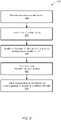
- FIG. 5 is a simplified diagram showing a method for isolating network traffic of multiple users across a network of a computing platform according to one embodiment of the present invention.
- the method 500 includes processes 502-510 that are performed using one or more processors.
- processes 502-510 that are performed using one or more processors.
- the above has been shown using a selected group of processes for the method, there can be many alternatives, modifications, and variations. For example, some of the processes may be expanded and/or combined. Other processes may be inserted to those noted above. Depending upon the embodiment, the sequence of processes may be interchanged with others replaced.
- some or all processes (e.g., steps) of the method 500 are performed by the system 100. In certain examples, some or all processes (e.g., steps) of the method 500 are performed by a computer and/or a processor directed by a code.
- a computer includes a server computer and/or a client computer (e.g., a personal computer). In some examples, some or all processes (e.g., steps) of the method 500 are performed according to instructions included by a non-transitory computer-readable medium (e.g., in a computer program product, such as a computer-readable flash drive).
- a non-transitory computer-readable medium is readable by a computer including a server computer and/or a client computer (e.g., a personal computer, and/or a server rack).
- instructions included by a non-transitory computer-readable medium are executed by a processor including a processor of a server computer and/or a processor of a client computer (e.g., a personal computer, and/or server rack).
- data is received at a networking device of a computing platform.
- the networking device includes a plurality of routing tables.
- each routing table of the plurality of routing tables are associated with a different user of multiple users of the computing platform.
- a user of the multiple users is identified based at least in part on the received data.
- a routing table of the plurality of routing tables is identified based at least in part on the identified user.
- a route from the identified routing table is determined based at least in part on the received data.
- the received data is sent across a first network of the computing platform according to the determined route.
- FIG. 6 is a simplified diagram showing a computing system for implementing a system for isolating network traffic of multiple users across a network of a computing platform according to one embodiment of the present invention.
- the computing system 600 includes a bus 602 or other communication mechanism for communicating information, a processor 604, a display 606, a cursor control component 608, an input device 610, a main memory 612, a read only memory (ROM) 614, a storage unit 616, and a network interface 618.
- some or all processes (e.g., steps) of the method 500 are performed by the computing system 600.
- the bus 602 is coupled to the processor 604, the display 606, the cursor control component 606, the input device 610, the main memory 612, the read only memory (ROM) 614, the storage unit 616, and/or the network interface 618.
- the network interface is coupled to a network 620.
- the processor 604 includes one or more general purpose microprocessors.
- the main memory 612 e.g., random access memory (RAM), cache and/or other dynamic storage devices
- the main memory 612 is configured to store information and instructions to be executed by the processor 604.
- the main memory 612 is configured to store temporary variables or other intermediate information during execution of instructions to be executed by processor 604.
- the instructions when stored in the storage unit 616 accessible to processor 604, render the computing system 600 into a special-purpose machine that is customized to perform the operations specified in the instructions.
- the ROM 614 is configured to store static information and instructions for the processor 604.
- the storage unit 616 e.g., a magnetic disk, optical disk, or flash drive
- the storage unit 616 is configured to store information and instructions.
- the display 606 e.g., a cathode ray tube (CRT), an LCD display, or a touch screen
- the input device 610 e.g., alphanumeric and other keys
- the cursor control 608 e.g., a mouse, a trackball, or cursor direction keys
- additional information and commands e.g., to control cursor movements on the display 606) to the processor 604.
- a method for isolating network traffic of multiple users across a network of a computing platform includes receiving data at a networking device of a computing platform.
- the networking device includes a plurality of routing tables. Each routing table of the plurality of routing tables is associated with a different user of multiple users of the computing platform.
- the method further includes identifying a user of the multiple users based at least in part on the received data.
- a routing table of the plurality of routing tables is identified based at least in part on the identified user.
- the method further includes determining a route from the identified routing table based at least in part on the received data, and sending the received data across a network of the computing platform according to the determined route.
- the method is performed using one or more processors. For example, the method is implemented according to at least FIG. 1 , FIG. 2 , FIG. 3 , FIG. 4 and/or FIG. 5 .
- the received data includes a unique user identification number related to the identified user, and the identified routing table is associated with the unique user identification number.
- a first routing table of the plurality of routing tables includes a first route.
- a second routing table of the plurality of routing tables includes a second route, and the first route and the second route are different.
- a first routing table of the plurality of routing tables includes a first route.
- a second routing table of the plurality of routing tables includes a second route, and the first route and the second route are the same and relate to a default route.
- the sending the received data across a first network of the computing platform according to the determined route includes: tagging the received data for sending across a broadcast domain of a plurality of broadcast domains; and sending the received data across the broadcast domain associated with the identified user.
- the broadcast domain is associated with the identified user.
- Each broadcast domain of the plurality of broadcast domains is isolated from any other broadcast domain of the plurality of broadcast domains and is associated with a different user of the multiple users of the computing platform.
- the broadcast domains are isolated from each other at a data link layer of the first network. At least two broadcast domains of the isolated broadcast domains are connected through a network layer of the first network. The at least two broadcast domains are associated with the identified user.
- the method further includes: configuring a first routing table of the plurality of routing tables by using a second network.
- the first network includes one or more first network connections and one or more first network interfaces.
- the second network includes one or more second network connections and one or more second network interfaces.
- the one or more first network connections and the one or more second network connections are different.
- the one or more first network interfaces and the one or more second network interfaces are different.
- the configuring a first routing table of the plurality of routing tables by using a second network include: copying one or more routes from a second routing table of the plurality of routing tables into the first routing table.
- the first routing table is associated with a first user of the multiple users of the computing platform.
- the second routing table is associated with a second user of the multiple users of the computing platform, and the first user and the second user are different
- a system for isolating network traffic of multiple users across a network of a computing platform includes a plurality of hosts; a networking device, and a network connecting the plurality of hosts and the networking device.
- the networking device includes a network layer and a plurality of routing tables. Each routing table of the plurality of routing tables is associated with a different user of multiple users of a computing platform.
- the networking device is configured to: receive data at the network layer from a first host of the plurality of hosts; identify a user of the multiple users based at least in part on the received data; in response to identifying the user of the multiple users based at least in part on the received data, identify a routing table of the plurality of routing tables based at least in part on the identified user; determine a route from the identified routing table based at least in part on the received data; and send the received data according to the determined route across the network to a second host of the plurality of hosts.
- the system is implemented according to at least FIG. 1 , FIG. 2 , FIG. 3 , and/or FIG. 4 .
- the received data includes a unique user identification number related to the identified user, and the identified routing table is associated with the unique user identification number.
- a first routing table of the plurality of routing tables includes a first route.
- a second routing table of the plurality of routing tables includes a second route, and the first route and the second route are different.
- a first routing table of the plurality of routing tables includes a first route.
- a second routing table of the plurality of routing tables includes a second route, and the first route and the second route are the same and relate to a default route.
- the system further includes a plurality of broadcast domains. Each broadcast domain is associated with one or more hosts of the plurality of hosts and connecting the one or more hosts.
- the networking device is further configured to: tag the received data for sending across a broadcast domain of the plurality of broadcast domains; and send the received data across the broadcast domain associated with the identified user.
- the broadcast domain is associated with the identified user.
- Each host of the plurality of hosts is associated with only one broadcast domain of the plurality of broadcast domains.
- Each broadcast domain of the plurality of broadcast domains is isolated from any other broadcast domain of the plurality of broadcast domains.
- Each broadcast domain of the plurality of broadcast domains is associated with a different user of the multiple users of the computing platform.
- a network layer for isolating network traffic of multiple users of a computing platform is provided.
- the network layer is configured to: identify a user of multiple users of a computing platform based at least in part on network data send across a network of the computing platform; in response to identifying the user of the multiple users based at least in part on the network data send across the network of the computing platform, identify a routing table of a plurality of routing tables based at least in part on the identified user. Each routing table of the plurality of routing tables are associated with a different user of the multiple users of the computing platform.
- the network layer is further configured to: determine a route from the identified routing table based at least in part on the network data; and route the network data according to the determined route across the network of the computing platform.
- the network layer is implemented according to at least FIG. 4 , and/or FIG. 5 .
- a first routing table of the plurality of routing tables includes a first route.
- a second routing table of the plurality of routing tables includes a second route, and the first route and the second route are different.
- a first routing table of the plurality of routing tables includes a first route.
- a second routing table of the plurality of routing tables includes a second route, and the first route and the second route are the same and relate to a default route.
- some or all components of various embodiments of the present invention each are, individually and/or in combination with at least another component, implemented using one or more software components, one or more hardware components, and/or one or more combinations of software and hardware components.
- some or all components of various embodiments of the present invention each are, individually and/or in combination with at least another component, implemented in one or more circuits, such as one or more analog circuits and/or one or more digital circuits.
- the embodiments described above refer to particular features, the scope of the present invention also includes embodiments having different combinations of features and embodiments that do not include all of the described features.
- various embodiments and/or examples of the present invention can be combined.
- the methods and systems described herein may be implemented on many different types of processing devices by program code comprising program instructions that are executable by the device processing subsystem.
- the software program instructions may include source code, object code, machine code, or any other stored data that is operable to cause a processing system to perform the methods and operations described herein.
- Other implementations may also be used, however, such as firmware or even appropriately designed hardware configured to perform the methods and systems described herein.
- the systems' and methods' data may be stored and implemented in one or more different types of computer-implemented data stores, such as different types of storage devices and programming constructs (e.g., RAM, ROM, EEPROM, Flash memory, flat files, databases, programming data structures, programming variables, IF-THEN (or similar type) statement constructs, application programming interface, etc.).
- storage devices and programming constructs e.g., RAM, ROM, EEPROM, Flash memory, flat files, databases, programming data structures, programming variables, IF-THEN (or similar type) statement constructs, application programming interface, etc.
- data structures describe formats for use in organizing and storing data in databases, programs, memory, or other computer-readable media for use by a computer program.
- the systems and methods may be provided on many different types of computer-readable media including computer storage mechanisms (e.g., CD-ROM, diskette, RAM, flash memory, computer's hard drive, DVD, etc.) that contain instructions (e.g., software) for use in execution by a processor to perform the methods' operations and implement the systems described herein.
- computer storage mechanisms e.g., CD-ROM, diskette, RAM, flash memory, computer's hard drive, DVD, etc.
- instructions e.g., software
- the computer components, software modules, functions, data stores and data structures described herein may be connected directly or indirectly to each other in order to allow the flow of data needed for their operations.
- a module or processor includes a unit of code that performs a software operation, and can be implemented for example as a subroutine unit of code, or as a software function unit of code, or as an object (as in an objectoriented paradigm), or as an applet, or in a computer script language, or as another type of computer code.
- the software components and/or functionality may be located on a single computer or distributed across multiple computers depending upon the situation at hand.
- the computing system can include client devices and servers.
- a client device and server are generally remote from each other and typically interact through a communication network.
- the relationship of client device and server arises by virtue of computer programs running on the respective computers and having a client device-server relationship to each other.
Description
- Certain embodiments of the present invention are directed to computing platforms including hosts and networking devices. More particularly, some embodiments of the present invention provide systems and methods for isolating network traffic of multiple users across networks of computing platforms.
- With the number of customers of a computing platform increasing, the demands on data security provided by the computing platform are also increasing. In some examples, customers are running their applications on multiple hosts across the computing platform sharing resources and the network of the computing platform. Thus, managing network traffic and ensuring data security across a computing platform becomes increasingly more complex with the number of customers increasing. For example, conventional computing platforms generally require extensive network configurations to isolate network traffic and data from multiple customers across a network of a computing platform. Examples of conventional network configurations include the use of firewalls and access control lists that are difficult to implement and manage for an increased number of customers of the platform.
- Hence it is highly desirable to improve the techniques for isolating network traffic of multiple users associated with different customers across networks of computing platforms.
US 9 014 191 US 2015/326467 discloses technology for bridging clouds of computing devices for compute and data storage. - The present invention is defined in the appended independent claims to which reference should be made. Advantageous features are set out in the appended dependent claims.
-
-
FIG. 1 is a simplified diagram showing a system for isolating network traffic of multiple users across a network of a computing platform according to one embodiment of the present invention. -
FIG. 2 is a simplified diagram showing the computing platform as part of the system for isolating network traffic of multiple users across the network as shown inFIG. 1 according to one embodiment of the present invention. -
FIG. 3 is a simplified diagram showing the computing platform as part of the system for isolating network traffic of multiple users across the network as shown inFIG. 1 according to one embodiment of the present invention. -
FIG. 4 is a simplified diagram showing the computing platform as part of the system for isolating network traffic of multiple users across the network as shown inFIG. 1 according to one embodiment of the present invention. -
FIG. 5 is a simplified diagram showing a method for isolating network traffic of multiple users across a network of a computing platform according to one embodiment of the present invention. -
FIG. 6 is a simplified diagram showing a computing system for implementing a system for isolating network traffic of multiple users across a network of a computing platform according to one embodiment of the present invention. - Conventional systems and methods are often not capable of efficiently isolating network traffic of multiple users associated with different customers across a network of a computing platform. Conventional systems and methods typically use firewalls and access control lists to guarantee data security of network traffic at the network layer within a multi-tenant computing platform, which leads to increased cost and decreased efficiency, and is more difficult to manage when scaling up the platform.
- In some embodiments, benefits include significant improvements, including, for example, increased efficiency, reduced complexity, and improved scalability, in managing network traffic of an increased number of users across a network of a computing platform. In certain embodiments, other benefits include increased data security at the networking level of the computing platform. In some embodiments, systems and methods are configured to isolate network traffic of multiple users across a network of a computing platform.
- In certain embodiments, one or more solutions rooted in computer technology overcome one or more problems specifically arising in the realm of computer technology. Some embodiments are directed to computing platforms including hosts and networking devices. More particularly, some embodiments of the present invention provide systems and methods for isolating network traffic of multiple users across networks of computing platforms. In some examples, the computing platforms include virtual servers or virtual machines. In certain examples, the computing platforms include a virtual computing environment that provides an operating system and/or an application server for running one or more containers. For example, a container includes a containerized application. In some examples, one or more containers run on a server or host machine of the computing platform and are associated with particular resources that include CPU, memory, storage, and/or networking capacity.
- According to some embodiments, network traffic for multiple users associated with different customers (e.g., different tenants) of a multi-tenant computing platform is isolated at the network layer of the network by having separate routing tables for each user. This, for example, eliminates the need for firewalls and access control lists to guarantee data security in the multi-tenant computing platform. In some examples, a user represents a group of users. As an example, the group of users is associated with a customer (e.g., a tenant) of the multi-tenant computing platform. In some examples, each user is associated with only one customer (e.g., only one tenant) of the multi-tenant computing platform that provides services to multiple customers. In certain examples, each routing table is associated with a unique user identification number to isolate network routes in one routing tables from routes in another routing table based at least in part on the unique user identification number. In some examples, the routing tables reside on networking devices of the computing platform, which direct data packets tagged with the unique user identification number based on routes in the routing table associated with the same unique user identification number. In certain examples, the unique user identification number represents a unique customer identification number.
- According to certain embodiments, the isolation of routes at the network layer of the network mirrors the isolation of broadcast domains of the computing platform at the data link layer of the network. In some examples, the isolation at the data link layer is based on the same unique user identification number and extended over the network layer of the network. In other examples, systems and methods allow for leaking routes between separate routing tables and sharing default routes with all user of the computing platform. For example, each separate routing table is associated with a different unique user identification number. In some examples, configuration of networking devices, including configuration of the routing tables on the networking devices, is managed through a management network that is separate from the network used by the users' network traffic.
-
FIG. 1 is a simplified diagram showing asystem 100 for isolating network traffic of multiple users across a network of acomputing platform 102 according to one embodiment of the present invention. This diagram is merely an example, which should not unduly limit the scope of the claims. One of ordinary skill in the art would recognize many variations, alternatives, and modifications. Thesystem 100 includes thecomputing platform 102, a network 104 (e.g., a production network), a plurality ofhosts hosts 1061-m representhosts 1061, ..., 106m as shown inFIG. 1 ,hosts 1081-n representhosts 1081, ..., 108n as shown inFIG. 1 ,hosts 1101-o representhosts 1101, ..., 110o as shown inFIG. 1 , and networking devices 1121-N represent networking devices 1121, ..., 112N as shown inFIG. 1 . - In some embodiments, the
computing platform 102 further includes one or more client devices 1141-M, anadministration device 116, a network 118 (e.g., a management network), and/or a network 120 (e.g., an edge network). For example, client devices 1141-M represent client devices 1141, ..., 114M as shown inFIG. 1 . As an example, the one or more devices 1141-M are associated with a customer. In some examples, the network 120 (e.g., the edge network) is configured to connect the network 104 (e.g., the production network) to the Internet 122. In certain examples, the network 118 (e.g., the management network) is configured to connect theadministration device 116 to the plurality ofhosts administration device 116 to the one or more networking devices 1121-N. As an example, theadministration device 116 is configured to allow an administrator of thecomputing platform 102 to administer and/or configure the plurality of hosts 1061-m, 1081-n, 1101-o and/or the one or more networking devices 1121-N. In certain examples, the network 104 (e.g., the production network) is configured to connect the one or more client devices 1141-M, the plurality ofhosts hosts 1061-m, hosts 1081-n, and hosts 1101-o, respectively. - In certain embodiments, the network 104 (e.g., the production network) is configured to transmit all non-management communications, including for example, network traffic from users or tenants and/or control plane traffic of a control plane application. For example, the
computing platform 102 includes a control plane application configured to schedule and manage applications that run on the plurality ofhosts layer 1, a data link layer orlayer 2, and a network layer or layer 3). For example, the network 104 (e.g., the production network) includes an IPv4 network, an IPv6 network, or any combination thereof. - According to some embodiments, the network 118 (e.g., the management network) is configured to boot (e.g., to PXE boot) the operating system on one or more components (e.g., one or more hosts of the
hosts computing platform 102. In some examples, the network 118 (e.g., the management network) is configured to perform and manage certain functions of thecomputing platform 102, including, for example, functions related to a network time protocol (NTP) and/or an intelligent platform management interface (IPMI). In certain examples, the network 118 (e.g., the management network) includes at least three networking layers (e.g., a physical layer orlayer 1, a data link layer orlayer 2, and a network layer or layer 3). For example, the network 118 (e.g., the management network) includes an IPv4 network, an IPv6 network, or any combination thereof. - According to certain embodiments, the network 120 (e.g., the edge network) is configured to transmit traffic from carrier drops associated with pods and/or applications running on devices and/or servers (e.g., hosts 1061-m, 1081-n, 1101-o) of the network 104 (e.g., the production network). In some examples, the network 120 (e.g., the edge network) includes at least three networking layers (e.g., a physical layer or
layer 1, a data link layer orlayer 2, and a network layer or layer 3). - In some embodiments, the
computing platform 102 includes a cluster computing platform including clusters of the one or more server or host machines (e.g. clusters of thehosts computing platform 102 includes a distributed computing platform that allows the one or more device clients 1141-M to distribute applications and/or data over the network 104 (e.g., the production network) to the cluster of servers or host machines (e.g. the clusters of thehosts computing platform 102 includes a cloud computing platform that allows the one or more device clients 1141-M access to remote servers, data storages, networks, devices, applications and/or data resources over the network 104 (e.g., the production network). For example, multiple users through the one or more client devices 1141-M store data at the data storages of the cloud computing platform. In other examples, thecomputing platform 102 is associated with a platform provider that provides the platform to multiple customers. For example, customers of thecomputing platform 102 include individuals, organizations and/or commercial companies. - In some embodiments, the one or more servers or host machines (e.g., the plurality of
hosts computing platform 102 is configured to not replicate applications and/or resources across different regions. For example, each region is completely independent from any other region of thecomputing platform 102. - In certain embodiments, the
computing platform 102 includes a container-orchestration platform. In some examples, the container-orchestration platform allows for automated deployment, scaling and/or operations of containers across the platform. For example, the container-orchestration platform employs the containers across the one or more servers or host machines of thecomputing platform 102. In some example, a pod of thecomputing platform 102 represents a basic scheduling unit of work on thecomputing platform 102. In certain examples, the pod includes one or more containers. In other examples, one or more pods of thecomputing platform 102 provide a service to the one or more client devices 1141-M. For example, each of the one or more client devices 1141-M is associated with a customer of themulti-tenant computing platform 102. - According to some embodiments, a container of the
computing platform 102 includes one or more applications. In some examples, the container also includes data and libraries associated with the one or more applications. For example, the container allows the one and more applications and their associated data and libraries to be co-located on the same server or host machine (e.g., the same host of the plurality ofhosts computing platform 102. In one example, the micro-service includes the one or more applications, libraries and the applications' dependencies. - In some embodiments, the
computing platform 102 includes a plurality of racks. In some examples, each rack of the plurality of racks includes one or more hosts and a networking device. For example, thecomputing platform 102 includes N racks with the first rack including thenetworking device 1121 and thehosts 1061-m, the second rack including thenetworking device 1122 and thehosts 1081-n, and the Nth rack including the networking device 112N and thehosts 1101-o. In certain examples, the networking devices 1121-N of the racks include top of rack (ToR) switches. For example, the physical layer of the network 118 (e.g., the management network) includes a 48x1GE ToR switch for each rack. As an example, each ToR switch of the network 118 (e.g., the management network) includes north-bound connections to a 2x aggregation switch running in the core. In some examples, each compute node (e.g., each host) in the rack is connected to a ToR switch of the physical layer of the network 118 (e.g., the management network) via an on-board 1GE network interface controller (NIC). - In certain embodiments, the data link layer of the network 118 (e.g., the management network) includes at least three virtual local area networks (VLANs) that span the entire network 118 (e.g., the entire management network). For example, the first VLAN includes an untagged VLAN used for PXE booting. As an example, the second VLAN includes a vlan 100 used for IPMI functions. In one example, the third VLAN includes a vlan 200 used for core management network services. In some examples, the default on the ToR switches of the network 118 (e.g., the management network) are configured to forward dynamic host configuration protocol (DHCP) requests so that DHCP spans all three VLANs.
- According to some embodiments, the network layer of the network 118 (e.g., the management network) includes a /24 subnets. For example, each ToR switch of the network 118 (e.g., the management network) is assigned to a /24 subnet. In some examples, the
computing platform 102 is configured to statically assign the internet protocol (IP) addresses of the network 118 (e.g., the management network) via DHCP service in core which allows assigning hostnames via internal domain name system (DNS). - According to certain embodiments, the network 104 (e.g., the production network) of computing platform is configured to provide connectivity via the border gateway protocol (BGP) and virtual routing and forwarding (VRF) technology over an ethernet virtual private network (EVPN). For example, the EVPN is implemented using VPN technology and virtual extensible local area network (VXLAN) technology to create virtual MAC addresses for the Lo interfaces that allows network traffic to be forwarded to the MAC address. In some examples, the network 104 (e.g., the production network) of computing platform includes point-to-point Open Shortest Path First (OSPF) to make the Lo interface routable for BGP. In certain examples, the network 104 (e.g., the production network) of computing platform includes loopback interfaces for peer BGP sessions across racks to allow BGP to flow across any active interface of the network 104 (e.g., the production network). In certain examples, the physical layer of the network 104 (e.g., the production network) includes 32x100GE ToR layer 3 switches for each rack. For example, each compute node (e.g., each host) of the racks is connected via 2x25GE QSFP28+ to a ToR switch of the network 104 (e.g., the production network). As an example, each ToR switch of the network 104 (e.g., the production network) includes north-bound connections to 2x aggregations running in the core. In one example, for the V0, each ToR switch of the network 104 (e.g., the production network) includes 2x100G uplinks to each aggregator for providing a 2:1 oversubscription.
-
FIG. 2 is a simplified diagram showing thecomputing platform 102 as part of thesystem 100 for isolating network traffic of multiple users across thenetwork 104 as shown inFIG. 1 according to one embodiment of the present invention. This diagram is merely an example, which should not unduly limit the scope of the claims. One of ordinary skill in the art would recognize many variations, alternatives, and modifications. In some examples, the networking device 1121 is configured to receivedata 200. For example, anapplication 202 associated with auser 2041 is configured to send thedata 200 to the networking device 1121 for forwarding thedata 200 according to aroute 206 across the network 104 (e.g., the production network). In some examples, theuser 2041 represents a group of users associated with a customer of thecomputing platform 102. In certain examples, the networking device 1121 includes a plurality of routing tables 2081-p. For example, routing tables 2081-p represent routing tables 2081, ..., 208p as shown inFIG. 2 . In other examples, the routing tables 2081-p includes one ormore routes 2101-p for routing thedata 200 across the network 104 (e.g., the production network). As an example,routes 2101-p representroutes 2101, ..., 210p as shown inFIG. 2 . In one example, each of theroutes 2101, ..., 210p include one or more routes. - In some embodiments, each routing table of the plurality of routing tables 2081-p is associated with a different user of
multiple users 2041-p of thecomputing platform 102. For example,users 2041-p representusers 2041, ..., 204p as shown inFIG. 2 . In certain examples, each routing table of the plurality of routing tables 2081-p is associated with a unique user identification number 212. For example, the unique user identification number 2121 relates touser 2041 of themultiple users 2041-p of thecomputing platform 102. In some examples, each routing table of the plurality of routing tables 2081-p is associated with a different customer of themulti-tenant computing platform 102. For example,user 2041 represents a group of users associated with a customer of themulti-tenant computing platform 102. As an example, the unique user identification number 2121 represents a unique customer identification number associated with the customer. - In certain embodiments, the networking device 1121 is configured to identify the
user 2041 of themultiple users 2041-p of thecomputing platform 102 based on the receiveddata 200. For example, the receiveddata 200 includes the unique user identification number 2121 relating to theuser 2041. In some examples, theuser 2041 represents a group of users associated with a customer of themulti-tenant computing platform 102. For example, the unique identification number 2121 represents a unique customer identification number associated with the customer. In certain examples, the networking device 112 is configured, in response to identifying theuser 2041, identify a routing table 2081 of the plurality of routing tables 2081-p based at least in part on the identifieduser 2041. For example, networking device 112 is configured to identify the routing table 2081 based on the unique user identification number 2121 associated with theuser 2041. As an example, the identified routing table 2121 includes the unique identification number 2121 associated with theuser 2041. In one example, the networking device 112 is configured to extract the unique user identification number 2121 from the receiveddata 200 and identify the routing table 2081 associated with the extracted unique user identification number 2121. - According to some embodiments, the networking device 1121 is configured to determine the
route 206 from the identified routing table 2081 based at least in part on the receiveddata 200. For example, the receiveddata 200 includes a unique route identification number. In some examples, the networking device 112 is configured to extract the unique route identification number (e.g., "2") from the receiveddata 200 and map the unique route identification number (e.g., "2") to the route 2141 (e.g., 2nd route) of the identified routing table 2081. For example, the route 2141 represents theroute 206 determined by the networking device 112. In certain examples, each route included in a routing table is associated with a unique route identification number (e.g., "1" for 1st route, "2" for 2nd route, etc.). In one example, the route 2141 represents the determinedroute 206. In other examples, the routing table 2081 associated withuser 2041 includes the route 2141 and the routing table 208p associated withuser 204p includes the route 214p. For the example, the route 2141 and the route 214p are different. As an example, the route 2141 and the route 214p are the same and relate to a default route. In other examples, theroutes 2101 of the routing table 2081 associated withuser 2041 are different from theroutes 210p of the routing table 208p associated withuser 204p. - According to certain embodiments, the networking device 1121 is configured to change the routing table 2081 in response to receiving a configuration request from the
administration device 116 via the network 118 (e.g., the management network). For example, the network 104 (e.g., the production network) includes one ormore network connections 216 and one or more network interfaces 218. As an example, the network 118 (e.g., the management network) includes one ormore network connections 220 and one or more network interfaces 222. In some examples, the one ormore network connections 216 and the one ormore network connections 220 are different. In certain examples, the one ormore network interfaces 218 and the one ormore network interfaces 222 are different. - In some embodiments, the networking device 1121 is configured to configure the routing table 2081 via the network 118 (e.g., the management network). In some examples, the networking device 1121 is configured to prevent configuring the routing table 2081 via the network 104 (e.g., the production network). In certain examples, the networking device 1121 is configured to copy the route 2141 from the routing table 2081 associated with
user 2041 into the routing table 208p associated withuser 204p. For example,user 2041 anduser 204p represent different users of thecomputing platform 102. In other examples,user 2041 anduser 204p represent two groups of users of thecomputing platform 102. For example, each group of users is associated with a different customer of themulti-tenant computing platform 102. As an example, the two groups of users associated with different customers do not share any common user. In some examples, the networking device 1121 is configured to, in response touser 2041 granting permission touser 204p, copy theroute 2041 from the routing table 2081 into the routing table 208p. - In certain embodiments, the data link layer of the network 104 (e.g., the production network) includes
layer 2 isolation on a per-user basis by assigning each user to a separate VLAN. For example, ToR ports of the network 104 (e.g., the production network) that are connecting down to the compute nodes include 802.1q trunks for carrying multiple VLANs. As an example, each compute node (e.g., each host) includes at least two VLANs with one VLAN for the control plane application and the other VLAN for the containers running on the compute node (e.g., the host). - According to some embodiments, the network layer of the network 104 (e.g., the production network) includes layer 3 isolation on a per-user, per-host basis to prevent undesired IP communication between different users of the
computing platform 102. In some examples, the layer 3 (L3) isolation is implemented using VRF tables and type-5 BGP sessions. For example, the networking devices 112 (e.g., the ToR switches) of thecomputing platform 102 are configured to assign each L3 user interface to a VRF table. In certain examples, the networking devices 112 (e.g., the ToR switches) are configured to assign each user a unique route identifier that is unique within the networks of thecomputing platform 102 and provides for per-user route injection into the VRF tables. For example, for each user the unique route identifier is associated with the unique user identification number. In other examples, the network 104 (e.g., the production network) ofcomputing platform 102 is configured to use type-5 BGP sessions for propagating routes between ToR switches within the context of VRF to allow for cross-rack communication while maintaining L3 isolation. For example, the networking devices 112 are configured to inject tagged routes into VRF tables as part of an BGP session. As an example, the route identifiers are unique across the BGP session propagation. In other examples, each VRF table includes a unique VRF identifier associated with a particular user of thecomputing platform 102. For example, the unique VRF identifiers are local for each ToR switch. -
FIG. 3 is a simplified diagram showing thecomputing platform 102 as part of thesystem 100 for isolating network traffic of multiple users across thenetwork 104 as shown inFIG. 1 according to one embodiment of the present invention. This diagram is merely an example, which should not unduly limit the scope of the claims. One of ordinary skill in the art would recognize many variations, alternatives, and modifications. In some examples, the network 104 (e.g., production network) of thecomputing platform 102 includes a plurality ofbroadcast domains 3001-p. For example,broadcast domains 3001-p representbroadcast domains 3001, ..., 300p as shown inFIG. 3 . In certain examples, each broadcast domain of the plurality ofbroadcast domains 3001-p is isolated from any other broadcast domain of the plurality ofbroadcast domains 3001-p. As an example, each broadcast domain includes different hosts of thecomputing platform 102. In one example, thebroadcast domain 3001 includes thehosts 1061-k and thebroadcast domain 300p includes thehosts 1061-m. - In some embodiments, each
broadcast domain 300 is associated with a user of the multiple users of thecomputing platform 102. For example, each broadcast domain of thebroadcast domains 3001-p is associated with a different user of themultiple users 2041-p of thecomputing platform 102. In some examples, a user of themultiple users 2041-p represents a group of users associated with a customer of themulti-tenant computing platform 102. For example, each broadcast domain of thebroadcast domains 3001-p is associated with only one customer of themulti-tenant computing platform 102. In certain examples, each broadcast domain of thebroadcast domains 3001-p is associated with only one routing table of the routing tables 2081-p of the networking device 1121. For example, each broadcast domain is associated with a different routing table. As an example,broadcast domain 3001 is associated with routing table 2081 andbroadcast domain 300p is associated with routing table 208p. In other examples, thebroadcast domains 3001-p include virtual local area networks. - In certain embodiments, the
broadcast domains 3001-p are isolated from each other at adata link layer 302 of thenetwork 104. In some examples, each broadcast domain includes a unique domain identification number. For example, thebroadcast domain 3001 is associated with the domain identification number "1". As an example, thebroadcast domain 300p is associated with the domain identification number "p". - According to some embodiments, the networking device 1121 is configured to tag the received
data 200 for sending across a broadcast domain of the plurality ofbroadcast domains 3001-p. For example, the networking device 1121 is configured to receive, at anetwork layer 304 of thecomputing platform 102, thedata 200 from anapplication 202 associated withuser 2041 via the network 104 (e.g., the production network). In some examples, the networking device 1121 is configured to identifyuser 2041 associated with thedata 200 and send thedata 200 across thebroadcast domain 3001 associated withuser 2041. -
FIG. 4 is a simplified diagram showing thecomputing platform 102 as part of thesystem 100 for isolating network traffic of multiple users across thenetwork 104 as shown inFIG. 1 according to one embodiment of the present invention. This diagram is merely an example, which should not unduly limit the scope of the claims. One of ordinary skill in the art would recognize many variations, alternatives, and modifications. In some examples, the network 104 (e.g., production network) of thecomputing platform 102 includes a plurality of broadcast domains. For example, each broadcast domain of the plurality of broadcast domains is isolated from any other broadcast domain of the plurality of broadcast domains at thedata link layer 302 of thenetwork 104. - In some embodiments, each broadcast domain includes different hosts of the
computing platform 102. For example, thebroadcast domain 4001 includes thehosts 1061-i. As an example, the broadcast domain 4021 includes thehosts 106j-k. In one example, hosts 106j-k representhosts 106j, ..., 106k as shown inFIG. 4 . In some examples, each broadcast domain of the plurality of broadcast domains is associated with only one user of the multiple users of thecomputing platform 102. For example, each broadcast domain is associated with a different user of the multiple users of thecomputing platform 102. In certain examples, a user of the multiple users represents a group of users associated with a customer of themulti-tenant computing platform 102. For example, each broadcast domain is associated with only one customer of themulti-tenant computing platform 102. - In certain embodiments, the networking device 1121 is configured to encapsulate frames of data for sending from the
broadcast domains 4001 to the broadcast domain 4021. In some examples, thebroadcast domain 4001 and the broadcast domain 4021 are connected through thenetwork layer 304 of thenetwork 104. In certain examples, thebroadcast domain 4001 and the broadcast domain 4021 are associated withuser 2041. In other examples,user 2041 represents a group of users associated with a customer of themulti-tenant computing platform 102, and thebroadcast domain 4001 and the broadcast domain 4021 are associated with the customer. In some examples, thebroadcast domain 4001 is connected to the networking device 1121 at the data link layer of the network 104 (e.g., the production network). In certain examples, the broadcast domain 4021 is connected to the networking device 112K at the data link layer of the network 104 (e.g., the production network). In other examples, the networking device 1121 is configured to send the encapsulated frames of the data from thebroadcast domains 4001 to the broadcast domain 4021 using thenetwork layer 304 of thenetwork 104. - According to some embodiments, each frame encapsulated by the networking device 1121 includes a network address associated with the
broadcast domain 4001 and a network address associated with the broadcast domain 4021. In some examples, thebroadcast domain 4001 includes a domain identification number (e.g., "1"). In certain examples, the broadcast domain 4021 includes a domain identification number (e.g., "1"). For example, the domain identification number of thebroadcast domain 4001 and the domain identification number of the broadcast domain 4021 are the same (e.g., "1"). As an example, the domain identification number of thebroadcast domain 4001 and the domain identification number of the broadcast domain 4021 are associated with a unique identification number related touser 2041. In some examples,user 2041 represents a group of users associated with a customer of themulti-tenant computing platform 102, and the unique identification number relates to the customer. -
FIG. 5 is a simplified diagram showing a method for isolating network traffic of multiple users across a network of a computing platform according to one embodiment of the present invention. This diagram is merely an example, which should not unduly limit the scope of the claims. One of ordinary skill in the art would recognize many variations, alternatives, and modifications. Themethod 500 includes processes 502-510 that are performed using one or more processors. Although the above has been shown using a selected group of processes for the method, there can be many alternatives, modifications, and variations. For example, some of the processes may be expanded and/or combined. Other processes may be inserted to those noted above. Depending upon the embodiment, the sequence of processes may be interchanged with others replaced. - In some embodiments, some or all processes (e.g., steps) of the
method 500 are performed by thesystem 100. In certain examples, some or all processes (e.g., steps) of themethod 500 are performed by a computer and/or a processor directed by a code. For example, a computer includes a server computer and/or a client computer (e.g., a personal computer). In some examples, some or all processes (e.g., steps) of themethod 500 are performed according to instructions included by a non-transitory computer-readable medium (e.g., in a computer program product, such as a computer-readable flash drive). For example, a non-transitory computer-readable medium is readable by a computer including a server computer and/or a client computer (e.g., a personal computer, and/or a server rack). As an example, instructions included by a non-transitory computer-readable medium are executed by a processor including a processor of a server computer and/or a processor of a client computer (e.g., a personal computer, and/or server rack). - In some embodiments, at the
process 502, data is received at a networking device of a computing platform. For example, the networking device includes a plurality of routing tables. As an example, each routing table of the plurality of routing tables are associated with a different user of multiple users of the computing platform. At theprocess 504, a user of the multiple users is identified based at least in part on the received data. At theprocess 506, in response to identifying the user of the multiple users based at least in part on the received data, a routing table of the plurality of routing tables is identified based at least in part on the identified user. At theprocess 508, a route from the identified routing table is determined based at least in part on the received data. At theprocess 510, the received data is sent across a first network of the computing platform according to the determined route. -
FIG. 6 is a simplified diagram showing a computing system for implementing a system for isolating network traffic of multiple users across a network of a computing platform according to one embodiment of the present invention. This diagram is merely an example, which should not unduly limit the scope of the claims. One of ordinary skill in the art would recognize many variations, alternatives, and modifications. Thecomputing system 600 includes a bus 602 or other communication mechanism for communicating information, aprocessor 604, adisplay 606, acursor control component 608, aninput device 610, amain memory 612, a read only memory (ROM) 614, astorage unit 616, and anetwork interface 618. In some embodiments, some or all processes (e.g., steps) of themethod 500 are performed by thecomputing system 600. In some examples, the bus 602 is coupled to theprocessor 604, thedisplay 606, thecursor control component 606, theinput device 610, themain memory 612, the read only memory (ROM) 614, thestorage unit 616, and/or thenetwork interface 618. In certain examples, the network interface is coupled to anetwork 620. For example, theprocessor 604 includes one or more general purpose microprocessors. In some examples, the main memory 612 (e.g., random access memory (RAM), cache and/or other dynamic storage devices) is configured to store information and instructions to be executed by theprocessor 604. In certain examples, themain memory 612 is configured to store temporary variables or other intermediate information during execution of instructions to be executed byprocessor 604. For examples, the instructions, when stored in thestorage unit 616 accessible toprocessor 604, render thecomputing system 600 into a special-purpose machine that is customized to perform the operations specified in the instructions. In some examples, theROM 614 is configured to store static information and instructions for theprocessor 604. In certain examples, the storage unit 616 (e.g., a magnetic disk, optical disk, or flash drive) is configured to store information and instructions. - In some embodiments, the display 606 (e.g., a cathode ray tube (CRT), an LCD display, or a touch screen) is configured to display information to a user of the
computing system 600. In some examples, the input device 610 (e.g., alphanumeric and other keys) is configured to communicate information and commands to theprocessor 604. For example, the cursor control 608 (e.g., a mouse, a trackball, or cursor direction keys) is configured to communicate additional information and commands (e.g., to control cursor movements on the display 606) to theprocessor 604. - According to some embodiments, a method for isolating network traffic of multiple users across a network of a computing platform includes receiving data at a networking device of a computing platform. The networking device includes a plurality of routing tables. Each routing table of the plurality of routing tables is associated with a different user of multiple users of the computing platform. The method further includes identifying a user of the multiple users based at least in part on the received data. In response to identifying the user of the multiple users based at least in part on the received data, a routing table of the plurality of routing tables is identified based at least in part on the identified user. The method further includes determining a route from the identified routing table based at least in part on the received data, and sending the received data across a network of the computing platform according to the determined route. The method is performed using one or more processors. For example, the method is implemented according to at least
FIG. 1 ,FIG. 2 ,FIG. 3 ,FIG. 4 and/orFIG. 5 . - In some examples, the received data includes a unique user identification number related to the identified user, and the identified routing table is associated with the unique user identification number. In certain examples, a first routing table of the plurality of routing tables includes a first route. A second routing table of the plurality of routing tables includes a second route, and the first route and the second route are different. In other examples, a first routing table of the plurality of routing tables includes a first route. A second routing table of the plurality of routing tables includes a second route, and the first route and the second route are the same and relate to a default route.
- The sending the received data across a first network of the computing platform according to the determined route includes: tagging the received data for sending across a broadcast domain of a plurality of broadcast domains; and sending the received data across the broadcast domain associated with the identified user. The broadcast domain is associated with the identified user. Each broadcast domain of the plurality of broadcast domains is isolated from any other broadcast domain of the plurality of broadcast domains and is associated with a different user of the multiple users of the computing platform.
- The broadcast domains are isolated from each other at a data link layer of the first network. At least two broadcast domains of the isolated broadcast domains are connected through a network layer of the first network. The at least two broadcast domains are associated with the identified user. In other examples, the method further includes: configuring a first routing table of the plurality of routing tables by using a second network. The first network includes one or more first network connections and one or more first network interfaces. The second network includes one or more second network connections and one or more second network interfaces. The one or more first network connections and the one or more second network connections are different. The one or more first network interfaces and the one or more second network interfaces are different.
- In some examples, the configuring a first routing table of the plurality of routing tables by using a second network include: copying one or more routes from a second routing table of the plurality of routing tables into the first routing table. The first routing table is associated with a first user of the multiple users of the computing platform. The second routing table is associated with a second user of the multiple users of the computing platform, and the first user and the second user are different
- According to certain embodiments, a system for isolating network traffic of multiple users across a network of a computing platform includes a plurality of hosts; a networking device, and a network connecting the plurality of hosts and the networking device. The networking device includes a network layer and a plurality of routing tables. Each routing table of the plurality of routing tables is associated with a different user of multiple users of a computing platform. The networking device is configured to: receive data at the network layer from a first host of the plurality of hosts; identify a user of the multiple users based at least in part on the received data; in response to identifying the user of the multiple users based at least in part on the received data, identify a routing table of the plurality of routing tables based at least in part on the identified user; determine a route from the identified routing table based at least in part on the received data; and send the received data according to the determined route across the network to a second host of the plurality of hosts. For example, the system is implemented according to at least
FIG. 1 ,FIG. 2 ,FIG. 3 , and/orFIG. 4 . - In some examples, the received data includes a unique user identification number related to the identified user, and the identified routing table is associated with the unique user identification number. In certain examples, a first routing table of the plurality of routing tables includes a first route. A second routing table of the plurality of routing tables includes a second route, and the first route and the second route are different. In other examples, a first routing table of the plurality of routing tables includes a first route. A second routing table of the plurality of routing tables includes a second route, and the first route and the second route are the same and relate to a default route. In some examples, the system further includes a plurality of broadcast domains. Each broadcast domain is associated with one or more hosts of the plurality of hosts and connecting the one or more hosts. The networking device is further configured to: tag the received data for sending across a broadcast domain of the plurality of broadcast domains; and send the received data across the broadcast domain associated with the identified user. The broadcast domain is associated with the identified user. Each host of the plurality of hosts is associated with only one broadcast domain of the plurality of broadcast domains. Each broadcast domain of the plurality of broadcast domains is isolated from any other broadcast domain of the plurality of broadcast domains. Each broadcast domain of the plurality of broadcast domains is associated with a different user of the multiple users of the computing platform.
- According to some embodiments, a network layer for isolating network traffic of multiple users of a computing platform is provided. The network layer is configured to: identify a user of multiple users of a computing platform based at least in part on network data send across a network of the computing platform; in response to identifying the user of the multiple users based at least in part on the network data send across the network of the computing platform, identify a routing table of a plurality of routing tables based at least in part on the identified user. Each routing table of the plurality of routing tables are associated with a different user of the multiple users of the computing platform. The network layer is further configured to: determine a route from the identified routing table based at least in part on the network data; and route the network data according to the determined route across the network of the computing platform. For example, the network layer is implemented according to at least
FIG. 4 , and/orFIG. 5 . - In some examples, a first routing table of the plurality of routing tables includes a first route. A second routing table of the plurality of routing tables includes a second route, and the first route and the second route are different. In certain examples, a first routing table of the plurality of routing tables includes a first route. A second routing table of the plurality of routing tables includes a second route, and the first route and the second route are the same and relate to a default route.
- For example, some or all components of various embodiments of the present invention each are, individually and/or in combination with at least another component, implemented using one or more software components, one or more hardware components, and/or one or more combinations of software and hardware components. In another example, some or all components of various embodiments of the present invention each are, individually and/or in combination with at least another component, implemented in one or more circuits, such as one or more analog circuits and/or one or more digital circuits. In yet another example, while the embodiments described above refer to particular features, the scope of the present invention also includes embodiments having different combinations of features and embodiments that do not include all of the described features. In yet another example, various embodiments and/or examples of the present invention can be combined.
- Additionally, the methods and systems described herein may be implemented on many different types of processing devices by program code comprising program instructions that are executable by the device processing subsystem. The software program instructions may include source code, object code, machine code, or any other stored data that is operable to cause a processing system to perform the methods and operations described herein. Other implementations may also be used, however, such as firmware or even appropriately designed hardware configured to perform the methods and systems described herein.
- The systems' and methods' data (e.g., associations, mappings, data input, data output, intermediate data results, final data results, etc.) may be stored and implemented in one or more different types of computer-implemented data stores, such as different types of storage devices and programming constructs (e.g., RAM, ROM, EEPROM, Flash memory, flat files, databases, programming data structures, programming variables, IF-THEN (or similar type) statement constructs, application programming interface, etc.). It is noted that data structures describe formats for use in organizing and storing data in databases, programs, memory, or other computer-readable media for use by a computer program.
- The systems and methods may be provided on many different types of computer-readable media including computer storage mechanisms (e.g., CD-ROM, diskette, RAM, flash memory, computer's hard drive, DVD, etc.) that contain instructions (e.g., software) for use in execution by a processor to perform the methods' operations and implement the systems described herein. The computer components, software modules, functions, data stores and data structures described herein may be connected directly or indirectly to each other in order to allow the flow of data needed for their operations. It is also noted that a module or processor includes a unit of code that performs a software operation, and can be implemented for example as a subroutine unit of code, or as a software function unit of code, or as an object (as in an objectoriented paradigm), or as an applet, or in a computer script language, or as another type of computer code. The software components and/or functionality may be located on a single computer or distributed across multiple computers depending upon the situation at hand.
- The computing system can include client devices and servers. A client device and server are generally remote from each other and typically interact through a communication network. The relationship of client device and server arises by virtue of computer programs running on the respective computers and having a client device-server relationship to each other.
Claims (9)
- A method for isolating network traffic of multiple users across a network of a computing platform (102), the method performed using one or more processors of a networking device (112) of the computer platform, the method comprising:receiving (502) data at the networking device, the networking device including a plurality of routing tables (208), each routing table of the plurality of routing tables being associated with a different user (204) of multiple users of the computing platform;identifying (504) a user of the multiple users based at least in part on the received data;in response to identifying the user of the multiple users based at least in part on the received data, identifying (506) a routing table of the plurality of routing tables based at least in part on the identified user;determining (508) a route from the identified routing table based at least in part on the received data; andsending (510) the received data across a first network of the computing platform according to the determined route, by:tagging the received data for sending across a broadcast domain of a plurality of broadcast domains, the broadcast domain being associated with the identified user; andsending the received data across the broadcast domain associated with the identified user;wherein each broadcast domain of the plurality of broadcast domains is isolated from any other broadcast domain of the plurality of broadcast domains at a data link layer and is associated with a different user of the multiple users of the computing platform and at least two broadcast domains of the isolated broadcast domains are connected through a network layer of the first network and are associated with the identified user.
- The method of claim 1, wherein receiving data at the networking device includes receiving data from an application associated with a user of the multiple users.
- The method of claim 1 or claim 2, wherein the computing platform is a multi-tenant computing platform which provides services to multiple customers, and wherein each user of the computing platform is associated with only one customer of the multi-tenant computing platform.
- The method of any preceding claim wherein:the received data includes a unique user identification number related to the identified user; andthe identified routing table is associated with the unique user identification number.
- The method of any preceding claim wherein:a first routing table of the plurality of routing tables includes a first route;a second routing table of the plurality of routing tables includes a second route; andthe first route and the second route are different.
- The method of any preceding claim, wherein:a first routing table of the plurality of routing tables includes a first route;a second routing table of the plurality of routing tables includes a second route; andthe first route and the second route are the same and relate to a default route.
- The method of any preceding claim, and further comprising:configuring a first routing table of the plurality of routing tables by using a second network;whereinthe first network includes one or more first network connections and one or more first network interfaces;the second network includes one or more second network connections and one or more second network interfaces;wherein:
the one or more first network connections and the one or more second network connections are different; andthe one or more first network interfaces and the one or more second network interfaces are different. - The method of claim 7 wherein the configuring a first routing table of the plurality of routing tables by using a second network includes:copying one or more routes from a second routing table of the plurality of routing tables into the first routing table;wherein:the first routing table is associated with a first user of the multiple users of the computing platform;the second routing table is associated with a second user of the multiple users of the computing platform; andthe first user and the second user are different.
- A system (100) for isolating network traffic of multiple users across a network of a
computing platform, the system comprising:a plurality of hosts (108);a networking device (112); anda network connecting the plurality of hosts and the networking device;wherein the networking device includes a network layer (304) and a plurality of routing tables (208), each routing table of the plurality of routing tables being associated with a different user of multiple users of a computing platform;wherein the networking device is configured to perform the method of any preceding claim.
Priority Applications (1)
| Application Number | Priority Date | Filing Date | Title |
|---|---|---|---|
| EP22195051.2A EP4142225A1 (en) | 2019-01-23 | 2019-07-04 | Systems and methods for isolating network traffic of multiple users across networks of computing platforms |
Applications Claiming Priority (2)
| Application Number | Priority Date | Filing Date | Title |
|---|---|---|---|
| US201962795998P | 2019-01-23 | 2019-01-23 | |
| US16/288,029 US11212224B1 (en) | 2019-01-23 | 2019-02-27 | Systems and methods for isolating network traffic of multiple users across networks of computing platforms |
Related Child Applications (2)
| Application Number | Title | Priority Date | Filing Date |
|---|---|---|---|
| EP22195051.2A Division-Into EP4142225A1 (en) | 2019-01-23 | 2019-07-04 | Systems and methods for isolating network traffic of multiple users across networks of computing platforms |
| EP22195051.2A Division EP4142225A1 (en) | 2019-01-23 | 2019-07-04 | Systems and methods for isolating network traffic of multiple users across networks of computing platforms |
Publications (3)
| Publication Number | Publication Date |
|---|---|
| EP3687117A1 EP3687117A1 (en) | 2020-07-29 |
| EP3687117B1 true EP3687117B1 (en) | 2022-10-19 |
| EP3687117B8 EP3687117B8 (en) | 2022-11-30 |
Family
ID=67437525
Family Applications (2)
| Application Number | Title | Priority Date | Filing Date |
|---|---|---|---|
| EP22195051.2A Pending EP4142225A1 (en) | 2019-01-23 | 2019-07-04 | Systems and methods for isolating network traffic of multiple users across networks of computing platforms |
| EP19184504.9A Active EP3687117B8 (en) | 2019-01-23 | 2019-07-04 | Systems and methods for isolating network traffic of multiple users across networks of computing platforms |
Family Applications Before (1)
| Application Number | Title | Priority Date | Filing Date |
|---|---|---|---|
| EP22195051.2A Pending EP4142225A1 (en) | 2019-01-23 | 2019-07-04 | Systems and methods for isolating network traffic of multiple users across networks of computing platforms |
Country Status (2)
| Country | Link |
|---|---|
| US (3) | US11212224B1 (en) |
| EP (2) | EP4142225A1 (en) |
Families Citing this family (3)
| Publication number | Priority date | Publication date | Assignee | Title |
|---|---|---|---|---|
| US11212224B1 (en) * | 2019-01-23 | 2021-12-28 | Palantir Technologies Inc. | Systems and methods for isolating network traffic of multiple users across networks of computing platforms |
| US20220308863A1 (en) * | 2020-03-31 | 2022-09-29 | ARRIS Enterprise LLC | Cloud-based computer with runtime-mapped software versions |
| US11659027B1 (en) * | 2022-01-06 | 2023-05-23 | Vmware, Inc. | Multi-network/domain service discovery in a container orchestration platform |
Family Cites Families (13)
| Publication number | Priority date | Publication date | Assignee | Title |
|---|---|---|---|---|
| US6396833B1 (en) * | 1998-12-02 | 2002-05-28 | Cisco Technology, Inc. | Per user and network routing tables |
| EP1107508A1 (en) * | 1999-12-06 | 2001-06-13 | Telefonaktiebolaget Lm Ericsson | System, method and computer program product for sending broadcast messages |
| US7715380B2 (en) | 2003-06-19 | 2010-05-11 | Cisco Technology, Inc. | Apparatus and methods for handling shared services through virtual route forwarding (VRF)-aware-NAT |
| WO2011014668A2 (en) * | 2009-07-30 | 2011-02-03 | Zinan Chen | Independent carrier ethernet interconnection platform |
| US9014191B1 (en) | 2012-09-28 | 2015-04-21 | Google Inc. | Separating routing domains for virtualized networks when implementing a tunneling protocol |
| US10715435B2 (en) * | 2014-04-09 | 2020-07-14 | Red Hat, Inc. | Routing tier for highly-available applications on a multi-tenant platform-as-a-service (PaaS) system |
| US9226217B2 (en) * | 2014-04-17 | 2015-12-29 | Twilio, Inc. | System and method for enabling multi-modal communication |
| US10484471B2 (en) | 2014-05-12 | 2019-11-19 | Netapp, Inc. | Bridging clouds |
| US9516101B2 (en) * | 2014-07-07 | 2016-12-06 | Twilio, Inc. | System and method for collecting feedback in a multi-tenant communication platform |
| US10148618B2 (en) | 2016-06-07 | 2018-12-04 | Abb Schweiz Ag | Network isolation |
| US10749840B2 (en) * | 2016-07-08 | 2020-08-18 | Waldemar Augustyn | Network communication method and apparatus |
| EP4040739B1 (en) * | 2017-02-28 | 2024-02-21 | Huawei Technologies Co., Ltd. | Optical line terminal olt device virtualization method and related device |
| US11212224B1 (en) * | 2019-01-23 | 2021-12-28 | Palantir Technologies Inc. | Systems and methods for isolating network traffic of multiple users across networks of computing platforms |
-
2019
- 2019-02-27 US US16/288,029 patent/US11212224B1/en active Active
- 2019-07-04 EP EP22195051.2A patent/EP4142225A1/en active Pending
- 2019-07-04 EP EP19184504.9A patent/EP3687117B8/en active Active
-
2021
- 2021-11-17 US US17/529,081 patent/US11722411B2/en active Active
-
2023
- 2023-06-16 US US18/210,966 patent/US20230336481A1/en active Pending
Also Published As
| Publication number | Publication date |
|---|---|
| EP3687117B8 (en) | 2022-11-30 |
| US11722411B2 (en) | 2023-08-08 |
| US20230336481A1 (en) | 2023-10-19 |
| EP4142225A1 (en) | 2023-03-01 |
| US11212224B1 (en) | 2021-12-28 |
| US20220078115A1 (en) | 2022-03-10 |
| EP3687117A1 (en) | 2020-07-29 |
Similar Documents
| Publication | Publication Date | Title |
|---|---|---|
| CN115380514B (en) | Automatic deployment of network elements for heterogeneous computing elements | |
| US11563681B2 (en) | Managing communications using alternative packet addressing | |
| US10547463B2 (en) | Multicast helper to link virtual extensible LANs | |
| US9912582B2 (en) | Multi-tenant isolation in a cloud environment using software defined networking | |
| US10033691B1 (en) | Adaptive resolution of domain name requests in virtual private cloud network environments | |
| EP3984181B1 (en) | L3 underlay routing in a cloud environment using hybrid distributed logical router | |
| US9363207B2 (en) | Private virtual local area network isolation | |
| US9900263B2 (en) | Non-overlay resource access in datacenters using overlay networks | |
| US11722411B2 (en) | Systems and methods for isolating network traffic of multiple users across networks of computing platforms | |
| US20170257269A1 (en) | Network controller with integrated resource management capability | |
| EP2847969B1 (en) | Method and apparatus for supporting access control lists in a multi-tenant environment | |
| US11082258B1 (en) | Isolation and segmentation in multi-cloud interconnects | |
| US20220210059A1 (en) | Internet group management protocol (igmp) of a layer-2 network in a virtualized cloud environment | |
| EP2648370A1 (en) | Location-Aware Virtual Service Provisioning in a Hybrid Cloud Environment | |
| US11777793B2 (en) | Location criteria for security groups | |
| US11949602B2 (en) | Stretched EPG and micro-segmentation in multisite fabrics | |
| US20210266255A1 (en) | Vrf segregation for shared services in multi-fabric cloud networks | |
| US20230300002A1 (en) | Mapping vlan of container network to logical network in hypervisor to support flexible ipam and routing container traffic | |
| US10826826B1 (en) | Supporting overlay networks for multiple autonomous systems and underlays | |
| US11924166B2 (en) | Resource-path-based, dynamic group membership support for membership groups | |
| US20240048485A1 (en) | Specifying routes to enable layer-2 mobility in hybrid-cloud environments | |
| US20240106832A1 (en) | Remote data planes for virtual private label clouds | |
| Cain et al. | Microsoft System Center Building a Virtualized Network Solution | |
| WO2018060761A1 (en) | Techniques for simplified service modification utilizing a split design-assign framework |
Legal Events
| Date | Code | Title | Description |
|---|---|---|---|
| PUAI | Public reference made under article 153(3) epc to a published international application that has entered the european phase |
Free format text: ORIGINAL CODE: 0009012 |
|
| STAA | Information on the status of an ep patent application or granted ep patent |
Free format text: STATUS: THE APPLICATION HAS BEEN PUBLISHED |
|
| AK | Designated contracting states |
Kind code of ref document: A1 Designated state(s): AL AT BE BG CH CY CZ DE DK EE ES FI FR GB GR HR HU IE IS IT LI LT LU LV MC MK MT NL NO PL PT RO RS SE SI SK SM TR |
|
| AX | Request for extension of the european patent |
Extension state: BA ME |
|
| STAA | Information on the status of an ep patent application or granted ep patent |
Free format text: STATUS: REQUEST FOR EXAMINATION WAS MADE |
|
| STAA | Information on the status of an ep patent application or granted ep patent |
Free format text: STATUS: EXAMINATION IS IN PROGRESS |
|
| 17P | Request for examination filed |
Effective date: 20210128 |
|
| RBV | Designated contracting states (corrected) |
Designated state(s): AL AT BE BG CH CY CZ DE DK EE ES FI FR GB GR HR HU IE IS IT LI LT LU LV MC MK MT NL NO PL PT RO RS SE SI SK SM TR |
|
| 17Q | First examination report despatched |
Effective date: 20210225 |
|
| GRAP | Despatch of communication of intention to grant a patent |
Free format text: ORIGINAL CODE: EPIDOSNIGR1 |
|
| STAA | Information on the status of an ep patent application or granted ep patent |
Free format text: STATUS: GRANT OF PATENT IS INTENDED |
|
| RIC1 | Information provided on ipc code assigned before grant |
Ipc: H04L 45/30 20220101ALI20220502BHEP Ipc: H04L 45/00 20220101ALI20220502BHEP Ipc: H04L 12/46 20060101AFI20220502BHEP |
|
| INTG | Intention to grant announced |
Effective date: 20220519 |
|
| RIN1 | Information on inventor provided before grant (corrected) |
Inventor name: WILLIAMSON, MATTHEW Inventor name: AUSTIN, STEVEN |
|
| GRAS | Grant fee paid |
Free format text: ORIGINAL CODE: EPIDOSNIGR3 |
|
| GRAA | (expected) grant |
Free format text: ORIGINAL CODE: 0009210 |
|
| STAA | Information on the status of an ep patent application or granted ep patent |
Free format text: STATUS: THE PATENT HAS BEEN GRANTED |
|
| AK | Designated contracting states |
Kind code of ref document: B1 Designated state(s): AL AT BE BG CH CY CZ DE DK EE ES FI FR GB GR HR HU IE IS IT LI LT LU LV MC MK MT NL NO PL PT RO RS SE SI SK SM TR |
|
| REG | Reference to a national code |
Ref country code: GB Ref legal event code: FG4D |
|
| REG | Reference to a national code |
Ref country code: CH Ref legal event code: EP |
|
| REG | Reference to a national code |
Ref country code: DE Ref legal event code: R096 Ref document number: 602019020732 Country of ref document: DE |
|
| REG | Reference to a national code |
Ref country code: DE Ref legal event code: R081 Ref document number: 602019020732 Country of ref document: DE Owner name: PALANTIR TECHNOLOGIES INC., DENVER, US Free format text: FORMER OWNER: PALANTIR TECHNOLOGIES INC., PALO ALTO, CA, US |
|
| REG | Reference to a national code |
Ref country code: IE Ref legal event code: FG4D |
|
| REG | Reference to a national code |
Ref country code: CH Ref legal event code: PK Free format text: BERICHTIGUNG B8 Ref country code: AT Ref legal event code: REF Ref document number: 1526257 Country of ref document: AT Kind code of ref document: T Effective date: 20221115 |
|
| RAP4 | Party data changed (patent owner data changed or rights of a patent transferred) |
Owner name: PALANTIR TECHNOLOGIES INC. |
|
| REG | Reference to a national code |
Ref country code: LT Ref legal event code: MG9D |
|
| REG | Reference to a national code |
Ref country code: NL Ref legal event code: MP Effective date: 20221019 |
|
| REG | Reference to a national code |
Ref country code: AT Ref legal event code: MK05 Ref document number: 1526257 Country of ref document: AT Kind code of ref document: T Effective date: 20221019 |
|
| PG25 | Lapsed in a contracting state [announced via postgrant information from national office to epo] |
Ref country code: NL Free format text: LAPSE BECAUSE OF FAILURE TO SUBMIT A TRANSLATION OF THE DESCRIPTION OR TO PAY THE FEE WITHIN THE PRESCRIBED TIME-LIMIT Effective date: 20221019 |
|
| PG25 | Lapsed in a contracting state [announced via postgrant information from national office to epo] |
Ref country code: SE Free format text: LAPSE BECAUSE OF FAILURE TO SUBMIT A TRANSLATION OF THE DESCRIPTION OR TO PAY THE FEE WITHIN THE PRESCRIBED TIME-LIMIT Effective date: 20221019 Ref country code: PT Free format text: LAPSE BECAUSE OF FAILURE TO SUBMIT A TRANSLATION OF THE DESCRIPTION OR TO PAY THE FEE WITHIN THE PRESCRIBED TIME-LIMIT Effective date: 20230220 Ref country code: NO Free format text: LAPSE BECAUSE OF FAILURE TO SUBMIT A TRANSLATION OF THE DESCRIPTION OR TO PAY THE FEE WITHIN THE PRESCRIBED TIME-LIMIT Effective date: 20230119 Ref country code: LT Free format text: LAPSE BECAUSE OF FAILURE TO SUBMIT A TRANSLATION OF THE DESCRIPTION OR TO PAY THE FEE WITHIN THE PRESCRIBED TIME-LIMIT Effective date: 20221019 Ref country code: FI Free format text: LAPSE BECAUSE OF FAILURE TO SUBMIT A TRANSLATION OF THE DESCRIPTION OR TO PAY THE FEE WITHIN THE PRESCRIBED TIME-LIMIT Effective date: 20221019 Ref country code: ES Free format text: LAPSE BECAUSE OF FAILURE TO SUBMIT A TRANSLATION OF THE DESCRIPTION OR TO PAY THE FEE WITHIN THE PRESCRIBED TIME-LIMIT Effective date: 20221019 Ref country code: AT Free format text: LAPSE BECAUSE OF FAILURE TO SUBMIT A TRANSLATION OF THE DESCRIPTION OR TO PAY THE FEE WITHIN THE PRESCRIBED TIME-LIMIT Effective date: 20221019 |
|
| PG25 | Lapsed in a contracting state [announced via postgrant information from national office to epo] |
Ref country code: RS Free format text: LAPSE BECAUSE OF FAILURE TO SUBMIT A TRANSLATION OF THE DESCRIPTION OR TO PAY THE FEE WITHIN THE PRESCRIBED TIME-LIMIT Effective date: 20221019 Ref country code: PL Free format text: LAPSE BECAUSE OF FAILURE TO SUBMIT A TRANSLATION OF THE DESCRIPTION OR TO PAY THE FEE WITHIN THE PRESCRIBED TIME-LIMIT Effective date: 20221019 Ref country code: LV Free format text: LAPSE BECAUSE OF FAILURE TO SUBMIT A TRANSLATION OF THE DESCRIPTION OR TO PAY THE FEE WITHIN THE PRESCRIBED TIME-LIMIT Effective date: 20221019 Ref country code: IS Free format text: LAPSE BECAUSE OF FAILURE TO SUBMIT A TRANSLATION OF THE DESCRIPTION OR TO PAY THE FEE WITHIN THE PRESCRIBED TIME-LIMIT Effective date: 20230219 Ref country code: HR Free format text: LAPSE BECAUSE OF FAILURE TO SUBMIT A TRANSLATION OF THE DESCRIPTION OR TO PAY THE FEE WITHIN THE PRESCRIBED TIME-LIMIT Effective date: 20221019 Ref country code: GR Free format text: LAPSE BECAUSE OF FAILURE TO SUBMIT A TRANSLATION OF THE DESCRIPTION OR TO PAY THE FEE WITHIN THE PRESCRIBED TIME-LIMIT Effective date: 20230120 |
|
| P01 | Opt-out of the competence of the unified patent court (upc) registered |
Effective date: 20230526 |
|
| REG | Reference to a national code |
Ref country code: DE Ref legal event code: R097 Ref document number: 602019020732 Country of ref document: DE |
|
| PG25 | Lapsed in a contracting state [announced via postgrant information from national office to epo] |
Ref country code: SM Free format text: LAPSE BECAUSE OF FAILURE TO SUBMIT A TRANSLATION OF THE DESCRIPTION OR TO PAY THE FEE WITHIN THE PRESCRIBED TIME-LIMIT Effective date: 20221019 Ref country code: RO Free format text: LAPSE BECAUSE OF FAILURE TO SUBMIT A TRANSLATION OF THE DESCRIPTION OR TO PAY THE FEE WITHIN THE PRESCRIBED TIME-LIMIT Effective date: 20221019 Ref country code: EE Free format text: LAPSE BECAUSE OF FAILURE TO SUBMIT A TRANSLATION OF THE DESCRIPTION OR TO PAY THE FEE WITHIN THE PRESCRIBED TIME-LIMIT Effective date: 20221019 Ref country code: DK Free format text: LAPSE BECAUSE OF FAILURE TO SUBMIT A TRANSLATION OF THE DESCRIPTION OR TO PAY THE FEE WITHIN THE PRESCRIBED TIME-LIMIT Effective date: 20221019 Ref country code: CZ Free format text: LAPSE BECAUSE OF FAILURE TO SUBMIT A TRANSLATION OF THE DESCRIPTION OR TO PAY THE FEE WITHIN THE PRESCRIBED TIME-LIMIT Effective date: 20221019 |
|
| PGFP | Annual fee paid to national office [announced via postgrant information from national office to epo] |
Ref country code: FR Payment date: 20230621 Year of fee payment: 5 |
|
| PLBE | No opposition filed within time limit |
Free format text: ORIGINAL CODE: 0009261 |
|
| STAA | Information on the status of an ep patent application or granted ep patent |
Free format text: STATUS: NO OPPOSITION FILED WITHIN TIME LIMIT |
|
| PG25 | Lapsed in a contracting state [announced via postgrant information from national office to epo] |
Ref country code: SK Free format text: LAPSE BECAUSE OF FAILURE TO SUBMIT A TRANSLATION OF THE DESCRIPTION OR TO PAY THE FEE WITHIN THE PRESCRIBED TIME-LIMIT Effective date: 20221019 Ref country code: AL Free format text: LAPSE BECAUSE OF FAILURE TO SUBMIT A TRANSLATION OF THE DESCRIPTION OR TO PAY THE FEE WITHIN THE PRESCRIBED TIME-LIMIT Effective date: 20221019 |
|
| 26N | No opposition filed |
Effective date: 20230720 |
|
| PGFP | Annual fee paid to national office [announced via postgrant information from national office to epo] |
Ref country code: GB Payment date: 20230620 Year of fee payment: 5 Ref country code: CH Payment date: 20230801 Year of fee payment: 5 |
|
| PG25 | Lapsed in a contracting state [announced via postgrant information from national office to epo] |
Ref country code: SI Free format text: LAPSE BECAUSE OF FAILURE TO SUBMIT A TRANSLATION OF THE DESCRIPTION OR TO PAY THE FEE WITHIN THE PRESCRIBED TIME-LIMIT Effective date: 20221019 |
|
| PGFP | Annual fee paid to national office [announced via postgrant information from national office to epo] |
Ref country code: DE Payment date: 20230620 Year of fee payment: 5 |
|
| PG25 | Lapsed in a contracting state [announced via postgrant information from national office to epo] |
Ref country code: MC Free format text: LAPSE BECAUSE OF FAILURE TO SUBMIT A TRANSLATION OF THE DESCRIPTION OR TO PAY THE FEE WITHIN THE PRESCRIBED TIME-LIMIT Effective date: 20221019 |
|
| PG25 | Lapsed in a contracting state [announced via postgrant information from national office to epo] |
Ref country code: MC Free format text: LAPSE BECAUSE OF FAILURE TO SUBMIT A TRANSLATION OF THE DESCRIPTION OR TO PAY THE FEE WITHIN THE PRESCRIBED TIME-LIMIT Effective date: 20221019 |
|
| PG25 | Lapsed in a contracting state [announced via postgrant information from national office to epo] |
Ref country code: LU Free format text: LAPSE BECAUSE OF NON-PAYMENT OF DUE FEES Effective date: 20230704 |
|
| PG25 | Lapsed in a contracting state [announced via postgrant information from national office to epo] |
Ref country code: LU Free format text: LAPSE BECAUSE OF NON-PAYMENT OF DUE FEES Effective date: 20230704 |